EP3687086A1 - Method and device for controlling downlink optical signal, and computer readable storage medium - Google Patents
Method and device for controlling downlink optical signal, and computer readable storage medium Download PDFInfo
- Publication number
- EP3687086A1 EP3687086A1 EP18859779.3A EP18859779A EP3687086A1 EP 3687086 A1 EP3687086 A1 EP 3687086A1 EP 18859779 A EP18859779 A EP 18859779A EP 3687086 A1 EP3687086 A1 EP 3687086A1
- Authority
- EP
- European Patent Office
- Prior art keywords
- optical signal
- downlink optical
- onu
- downlink
- power
- Prior art date
- Legal status (The legal status is an assumption and is not a legal conclusion. Google has not performed a legal analysis and makes no representation as to the accuracy of the status listed.)
- Granted
Links
Images



Classifications
-
- H—ELECTRICITY
- H04—ELECTRIC COMMUNICATION TECHNIQUE
- H04Q—SELECTING
- H04Q11/00—Selecting arrangements for multiplex systems
- H04Q11/0001—Selecting arrangements for multiplex systems using optical switching
- H04Q11/0062—Network aspects
- H04Q11/0067—Provisions for optical access or distribution networks, e.g. Gigabit Ethernet Passive Optical Network (GE-PON), ATM-based Passive Optical Network (A-PON), PON-Ring
-
- H—ELECTRICITY
- H04—ELECTRIC COMMUNICATION TECHNIQUE
- H04B—TRANSMISSION
- H04B10/00—Transmission systems employing electromagnetic waves other than radio-waves, e.g. infrared, visible or ultraviolet light, or employing corpuscular radiation, e.g. quantum communication
- H04B10/07—Arrangements for monitoring or testing transmission systems; Arrangements for fault measurement of transmission systems
- H04B10/075—Arrangements for monitoring or testing transmission systems; Arrangements for fault measurement of transmission systems using an in-service signal
- H04B10/079—Arrangements for monitoring or testing transmission systems; Arrangements for fault measurement of transmission systems using an in-service signal using measurements of the data signal
- H04B10/0795—Performance monitoring; Measurement of transmission parameters
- H04B10/07955—Monitoring or measuring power
-
- H—ELECTRICITY
- H04—ELECTRIC COMMUNICATION TECHNIQUE
- H04B—TRANSMISSION
- H04B10/00—Transmission systems employing electromagnetic waves other than radio-waves, e.g. infrared, visible or ultraviolet light, or employing corpuscular radiation, e.g. quantum communication
- H04B10/07—Arrangements for monitoring or testing transmission systems; Arrangements for fault measurement of transmission systems
- H04B10/075—Arrangements for monitoring or testing transmission systems; Arrangements for fault measurement of transmission systems using an in-service signal
- H04B10/079—Arrangements for monitoring or testing transmission systems; Arrangements for fault measurement of transmission systems using an in-service signal using measurements of the data signal
-
- H—ELECTRICITY
- H04—ELECTRIC COMMUNICATION TECHNIQUE
- H04B—TRANSMISSION
- H04B10/00—Transmission systems employing electromagnetic waves other than radio-waves, e.g. infrared, visible or ultraviolet light, or employing corpuscular radiation, e.g. quantum communication
- H04B10/27—Arrangements for networking
- H04B10/272—Star-type networks or tree-type networks
-
- H—ELECTRICITY
- H04—ELECTRIC COMMUNICATION TECHNIQUE
- H04B—TRANSMISSION
- H04B10/00—Transmission systems employing electromagnetic waves other than radio-waves, e.g. infrared, visible or ultraviolet light, or employing corpuscular radiation, e.g. quantum communication
- H04B10/29—Repeaters
- H04B10/291—Repeaters in which processing or amplification is carried out without conversion of the main signal from optical form
- H04B10/293—Signal power control
- H04B10/294—Signal power control in a multiwavelength system, e.g. gain equalisation
-
- H—ELECTRICITY
- H04—ELECTRIC COMMUNICATION TECHNIQUE
- H04B—TRANSMISSION
- H04B10/00—Transmission systems employing electromagnetic waves other than radio-waves, e.g. infrared, visible or ultraviolet light, or employing corpuscular radiation, e.g. quantum communication
- H04B10/60—Receivers
-
- H—ELECTRICITY
- H04—ELECTRIC COMMUNICATION TECHNIQUE
- H04J—MULTIPLEX COMMUNICATION
- H04J14/00—Optical multiplex systems
- H04J14/02—Wavelength-division multiplex systems
- H04J14/0221—Power control, e.g. to keep the total optical power constant
-
- H—ELECTRICITY
- H04—ELECTRIC COMMUNICATION TECHNIQUE
- H04J—MULTIPLEX COMMUNICATION
- H04J14/00—Optical multiplex systems
- H04J14/02—Wavelength-division multiplex systems
- H04J14/0227—Operation, administration, maintenance or provisioning [OAMP] of WDM networks, e.g. media access, routing or wavelength allocation
- H04J14/0241—Wavelength allocation for communications one-to-one, e.g. unicasting wavelengths
- H04J14/0242—Wavelength allocation for communications one-to-one, e.g. unicasting wavelengths in WDM-PON
- H04J14/0245—Wavelength allocation for communications one-to-one, e.g. unicasting wavelengths in WDM-PON for downstream transmission, e.g. optical line terminal [OLT] to ONU
- H04J14/0246—Wavelength allocation for communications one-to-one, e.g. unicasting wavelengths in WDM-PON for downstream transmission, e.g. optical line terminal [OLT] to ONU using one wavelength per ONU
-
- Y—GENERAL TAGGING OF NEW TECHNOLOGICAL DEVELOPMENTS; GENERAL TAGGING OF CROSS-SECTIONAL TECHNOLOGIES SPANNING OVER SEVERAL SECTIONS OF THE IPC; TECHNICAL SUBJECTS COVERED BY FORMER USPC CROSS-REFERENCE ART COLLECTIONS [XRACs] AND DIGESTS
- Y02—TECHNOLOGIES OR APPLICATIONS FOR MITIGATION OR ADAPTATION AGAINST CLIMATE CHANGE
- Y02D—CLIMATE CHANGE MITIGATION TECHNOLOGIES IN INFORMATION AND COMMUNICATION TECHNOLOGIES [ICT], I.E. INFORMATION AND COMMUNICATION TECHNOLOGIES AIMING AT THE REDUCTION OF THEIR OWN ENERGY USE
- Y02D30/00—Reducing energy consumption in communication networks
- Y02D30/70—Reducing energy consumption in communication networks in wireless communication networks
Definitions
- the present disclosure relates to the field of optical access technology, and in particular, to a method and a device for controlling a downlink optical signal in a passive optical network, and a computer-readable storage medium.
- an optical amplifier may be added at an optical line terminal (OLT) side to increase transmission optical power.
- OLT optical line terminal
- attenuation of links from different optical network units (ONUs) to an OLT differs, with a maximum difference of 15dB.
- an optical amplifier is added at the OLT side to increase power of a downlink optical signal
- a receiving optical power of an ONU when an ONU, whose initial receiving optical power is minimum, is in an appropriate receiving optical power range, a receiving optical power of an ONU, whose initial receiving optical power is maximum, may exceed a damage threshold, resulting in damage to an optical receiver. It can be seen that there is a risk of amplifying a downlink optical signal only by a fixed gain.
- a method for controlling a downlink optical signal in a passive optical network is provided and is applied to an ONU, and the method includes the following steps: monitoring power of a downlink optical signal in a process of receiving the downlink optical signal; and adjusting an attenuation value of a variable optical attenuator at an ONU side according to the power of the downlink optical signal until the power of the downlink optical signal falls within a preset power range, where the variable optical attenuator at the ONU side is located between an optical splitter and the ONU.
- a device for controlling a downlink optical signal in a passive optical network is further provided and is applied to an ONU, and the device includes a signal monitoring module configured to monitor power of a downlink optical signal in a process of receiving the downlink optical signal; and a first adjustment module configured to adjust an attenuation value of a variable optical attenuator at an ONU side according to the power of the downlink optical signal until the power of the downlink optical signal falls within a preset power range, where the variable optical attenuator at the ONU side is located between an optical splitter and the ONU.
- a device for controlling a downlink optical signal in a passive optical network is further provided and is applied to an ONU, and the device includes a processor, a memory and a communication bus.
- the communication bus is configured to realize connection and communication between the processor and the memory, and the processor is configured to execute programs stored in the memory for controlling a downlink optical signal in a passive optical network, so as to perform the steps of the above method for controlling a downlink optical signal in a passive optical network.
- a computer-readable storage medium is further provided, and stores one or more programs capable of being executed by one or more processors, so as to perform the steps of the above method for controlling a downlink optical signal in a passive optical network.
- a method for controlling a downlink optical signal in a passive optical network is provided and is applied at an ONU side. As shown in Fig. 1 , the method includes step S101 and step S102.
- step S101 power of a downlink optical signal is monitored in a process of receiving the downlink optical signal.
- An ONU is powered on, an optical receiver is turned on to receive a downlink optical signal through the optical receiver, and power of the downlink optical signal is monitored.
- step S102 an attenuation value of a variable optical attenuator at an ONU side is adjusted according to the power of the downlink optical signal until the power of the downlink optical signal falls within a preset power range.
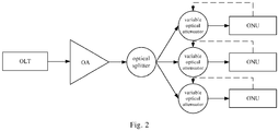
- Fig. 2 is a schematic diagram of a PON system according to an embodiment of the present disclosure.
- the PON system includes an OLT, an OA, an optical splitter, variable optical attenuators and ONUs.
- the OA is located between the OLT and the optical splitter.
- a branch of each ONU is provided thereon with a variable optical attenuator, which is located between the optical splitter and the ONU.
- a downlink optical signal transmitted by the OLT is amplified by the OA, and then passes through the optical splitter, and enters the branch of each ONU.
- the ONU adjusts an attenuation value of the variable optical attenuator according to power of a received downlink optical signal, stops adjusting the attenuation value of the variable optical attenuator when the power of the downlink optical signal falls within a power range in which the ONU can correctly receive a signal, starts waiting for a register window of the OLT to perform registration in the register window.
- the method before receiving the downlink optical signal, the method further includes the following step: adjusting the attenuation value of the variable optical attenuator to a maximum value.
- the step of adjusting the attenuation value of the variable optical attenuator at the ONU side until the power of the downlink optical signal falls within the preset power range includes the following step: gradually reducing the attenuation value of the variable optical attenuator until the power of the downlink optical signal falls within a preset power range.
- the ONU Before turning on the optical receiver, the ONU adjusts the attenuation value of the variable optical attenuator to the maximum value, so as to allow the optical receiver to receive a downlink optical signal with minimum power. And then the ONU gradually reduces the attenuation value of the variable optical attenuator according to the monitored power of the downlink optical signal to allow the optical receiver to receive a downlink optical signal with relatively large power.
- the method further includes the following step: performing registration by the ONU, and sending an adjusted attenuation value of the variable optical attenuator to the OLT by the ONU, so that the OLT can simultaneously reduce a gain value of the OA at an OLT side and attenuation values of the variable optical attenuators at the sides of all registered ONUs according to the attenuation values sent by all registered ONUs.
- each successfully registered ONU sends an adjusted attenuation value of the variable optical attenuator thereof to the OLT; and the OLT determines a minimum attenuation value I among the received attenuation values, and then simultaneously reduces a gain value of the OA at the OLT side by I and reduces attenuation values of the variable optical attenuators at the sides of all successfully registered ONUs by I, so that power of a downlink optical signal received by all successfully registered ONUs is unchanged and is still optimal receiving optical power, while energy is effectively saved by reducing the gain of the OA at the OLT side.
- the OLT When the OLT re-enters a register window, the OLT simultaneously increases the gain value of the OA at the OLT side by I and increases the attenuation values of the variable optical attenuators at the sides of previously successfully registered ONUs by I. When the new register window ends, the OLT reduces the gain of the OA at the OLT side through the above method.
- variable optical attenuator may be integrated with an ONU.
- the integration of the variable optical attenuator is achieved through a Micro-Electro-Mechanical System (MEMS).
- MEMS Micro-Electro-Mechanical System
- the ONU continuously receives downlink optical signals transmitted by the OLT, and adjusts the attenuation value of the variable optical attenuator in real time according to monitored power of the downlink optical signals, so as to keep the power of the received downlink optical signals in an optimal receiving range of the optical receiver all the time.
- the OA may also be integrated with an ONU.
- the integration of the OA is achieved through a Semiconductor Optical Amplifier (SOA).
- SOA Semiconductor Optical Amplifier
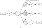
- the present disclosure provides a method for controlling a downlink optical signal in a passive optical network, which is applied at an ONU side in a passive optical network system shown in Fig. 3 which includes an OLT, an OLT-side OA, an optical splitter, variable optical attenuators, ONU-side OAs and ONUs.
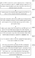
- the method includes steps S401 to S406.
- the OLT-side OA may be an OA located at or connected to the OLT, and an ONU-side OA may be an OA located at or connected to an ONU.
- the OLT-side OA is located between the OLT and the optical splitter; and a variable optical attenuator and an ONU-side OA are provided on a branch of each ONU, and are located between the optical splitter and the ONU.
- the positions of the variable optical attenuator and the ONU-side OA maybe interchanged.
- a downlink optical signal transmitted by the OLT is amplified by the OLT-side OA, and then passes through the optical splitter, and enters the branch of each ONU.
- step S401 an ONU is powered on, and an optical receiver is turned on, and then an attenuation value of the variable optical attenuator is adjusted to a maximum value and a gain value of the ONU-side OA is adjusted to a minimum value by the ONU.
- step S402 power of a downlink optical signal is monitored by the ONU in a process of receiving the downlink optical signal.
- step S403 an attenuation value of the variable optical attenuator is adjusted by the ONU according to the power of the downlink optical signal until the power of the downlink optical signal falls within a preset power range.
- the step S403 includes gradually reducing the attenuation value of the variable optical attenuator by the ONU until the power of the downlink optical signal falls within a preset power range.
- step S404 if the power of the downlink optical signal is still out of the preset power range when the attenuation value of the variable optical attenuator is adjusted to a minimum value, a gain value of the ONU-side OA is adjusted by the ONU until the power of the downlink optical signal falls within the preset power range.
- the power of the downlink optical signal is still out of the power range in which the ONU may correctly receive a signal when the attenuation value of the variable optical attenuator is adjusted to the minimum value, it indicates that the power of the downlink optical signal that has been amplified by the OLT-side OA is still not large enough, the power of the downlink optical signal needs to be further increased by the ONU-side OA until the ONU may correctly receive the downlink optical signal.
- step S404 includes gradually increasing the gain value of the ONU-side OA by the ONU until the power of the downlink optical signal falls within the preset power range.
- step S405 the ONU waits for a register window of the OLT and performs registration in the register window.
- step S406 after being successfully registered, the ONU continuously receives downlink optical signals transmitted by the OLT, monitors power of the downlink optical signals, and performs fine adjustment on the variable optical attenuator and the ONU-side OA in real time, so as to keep the power of the received downlink optical signals in an optimal receiving range of the optical receiver all the time.
- the present disclosure provides a device for controlling a downlink optical signal in a passive optical network, which is applied at an ONU side.
- the device specifically includes a signal monitoring module 501 and an adjustment module 502.
- the signal monitoring module 501 is configured to monitor power of a downlink optical signal in a process of receiving the downlink optical signal.
- An ONU is powered on, an optical receiver is turned on to receive a downlink optical signal through the optical receiver, and power of the downlink optical signal is monitored.
- the adjustment module 502 is configured to adjust an attenuation value of a variable optical attenuator at an ONU side according to the power of the downlink optical signal until the power of the downlink optical signal falls within a preset power range.
- the device may be applied to a PON system shown in Fig. 2 which includes an OLT, an OA, an optical splitter, variable optical attenuators and ONUs.
- the OA is located between the OLT and the optical splitter; and a branch of each ONU is provided thereon with a variable optical attenuator, which is located between the optical splitter and the ONU.
- a downlink optical signal transmitted by the OLT is amplified by the OA, and then passes through the optical splitter, and enters the branch of each ONU.
- the ONU adjusts an attenuation value of the variable optical attenuator according to power of a received downlink optical signal, stops adjusting the attenuation value of the variable optical attenuator when the power of the downlink optical signal falls within a power range in which the ONU may correctly receive a signal, starts waiting for a register window of the OLT, and performs registration in the register window.
- the device further includes a control adjustment module.
- the control adjustment module is configured to adjust an attenuation value of the variable optical attenuator to a maximum value before receiving the downlink optical signal.
- the adjustment module 502 is further configured to gradually reduce the attenuation value of the variable optical attenuator until the power of the downlink optical signal falls within the preset power range.
- the attenuation value of the variable optical attenuator is adjusted to the maximum value through the control adjustment module, so as to allow the optical receiver to receive a downlink optical signal with minimum power. And then, the ONU gradually reduces the attenuation value of the variable optical attenuator with the adjustment module 502 according to the monitored power of the downlink optical signal to allow the optical receiver to receive a downlink optical signal with relatively large power.
- the device further includes a feedback module.
- the feedback module is configured to send an adjusted attenuation value of the variable optical attenuator to the OLT when the ONU performs registration after the power of the downlink optical signal falls within the preset power range, so that the OLT may simultaneously reduce a gain value of the OA at an OLT side and attenuation values of the variable optical attenuators at the sides of all registered ONUs according to the attenuation values sent by all registered ONUs.
- each successfully registered ONU sends an adjusted attenuation value of the variable optical attenuator thereof through the feedback module to the OLT; and the OLT determines a minimum attenuation value I among the received attenuation values, and then simultaneously reduces a gain value of the OA at the OLT side by I and reduces attenuation values of the variable optical attenuators at the sides of all successfully registered ONUs by I, so that power of a downlink optical signal received by all successfully registered ONUs is unchanged and is still optimal receiving optical power, while energy is effectively saved by reducing the gain of the OA at the OLT side.
- the OLT When the OLT re-enters a register window, the OLT simultaneously increases the gain value of the OA at the OLT side by I and increases the attenuation values of the variable optical attenuators at the sides of previously successfully registered ONUs by I. When the new register window ends, the OLT reduces the gain of the OA at the OLT side through the above method.
- variable optical attenuator may be integrated with an ONU.
- the integration of the variable optical attenuator is achieved through a MEMS.
- the present disclosure provides a device for controlling a downlink optical signal in a passive optical network, which is applied at an ONU side in a PON system shown in Fig. 3 which includes an OLT, an OLT-side OA, an optical splitter, variable optical attenuators, ONU-side OAs and ONUs.
- the OLT-side OA is located between the OLT and the optical splitter; and a variable optical attenuator and an ONU-side OA are provided on a branch of each ONU, and are located between the optical splitter and the ONU.
- the positions of the variable optical attenuator and the ONU-side OA may be interchanged.
- a downlink optical signal transmitted by the OLT is amplified by the OLT-side OA, and then passes through the optical splitter, and enters the branch of each ONU.
- the device specifically includes a control adjustment module 601, a signal monitoring module 602, a first adjustment module 603, a second adjustment module 604, a registration module 605, and a fine adjustment module 606.
- the control adjustment module 601 is configured to adjust an attenuation value of the variable optical attenuator to a maximum value and adjust a gain value of the ONU-side OA to a minimum value after the ONU is powered on and an optical receiver is turned on.
- the signal monitoring module 602 is configured to monitor power of a downlink optical signal in a process of receiving the downlink optical signal.
- the first adjustment module 603 is configured to adjust the attenuation value of the variable optical attenuator according to the power of the downlink optical signal until the power of the downlink optical signal falls within a preset power range.
- the first adjustment module 603 is configured to gradually reduce the attenuation value of the variable optical attenuator until the power of the downlink optical signal falls within a preset power range.
- the second adjustment module 604 is configured to adjust the gain value of the ONU-side OA until the power of the downlink optical signal falls within the preset power range, if the power of the downlink optical signal is still out of the preset power range when the attenuation value of the variable optical attenuator is adjusted to a minimum value.
- the power of the downlink optical signal is still out of the power range in which the ONU may correctly receive a signal when the attenuation value of the variable optical attenuator is adjusted to the minimum value, it indicates that the power of the downlink optical signal that has been amplified by the OLT-side OA is still not large enough, the power of the downlink optical signal needs to be further increased by the ONU-side OA until the ONU may correctly receive the downlink optical signal.
- the second adjustment module 604 is configured to gradually increase the gain value of the ONU-side OA until the power of the downlink optical signal falls within the preset power range.
- the registration module 605 is configured to wait for a registerwindow of the OLT and perform registration in the register window.
- the fine adjustment module 606 is configured to, after the registration is successfully completed, continuously receive downlink optical signals transmitted by the OLT, monitor power of the downlink optical signals, and perform fine adjustment on the variable optical attenuator and the ONU-side OA in real time, so as to keep the power of the received downlink optical signals in an optimal receiving range of the optical receiver all the time.
- the present disclosure provides a device for controlling a downlink optical signal in a passive optical network, which is applied to an ONU.
- the device includes a processor 701, a memory 702, and a communication bus.
- the communication bus is configured to realize connection and communication between the processor 701 and the memory 702.
- the processor 701 is configured to execute programs stored in the memory 702 for controlling a downlink optical signal in a PON, so as to perform the following steps: monitoring power of a downlink optical signal in a process of receiving the downlink optical signal; and adjusting an attenuation value of a variable optical attenuator at an ONU side according to the power of the downlink optical signal until the power of the downlink optical signal falls within a preset power range.
- the present disclosure further provides a computer-readable storage medium which stores one or more programs capable of being executed by one or more processors to perform the steps of the above method for controlling a downlink optical signal in a passive optical network.
- the power of the downlink optical signal received by the ONU is adjusted to optimal receiving power of the optical receiver of the ONU by adjusting the variable optical attenuator and the OA at the ONU side, which solves the problems that the optical receiver is damaged due to excessive power of the downlink optical signal received at the ONU side when the OA is provided at the OLT side, and that the power of the downlink optical signal received at the ONU side is out of the optimal receiving range of the optical receiver.
Landscapes
- Engineering & Computer Science (AREA)
- Computer Networks & Wireless Communication (AREA)
- Signal Processing (AREA)
- Physics & Mathematics (AREA)
- Electromagnetism (AREA)
- Computing Systems (AREA)
- Optical Communication System (AREA)
Abstract
Description
- The present disclosure relates to the field of optical access technology, and in particular, to a method and a device for controlling a downlink optical signal in a passive optical network, and a computer-readable storage medium.
- At present, the technology of Passive Optical Network (PON) is being continuously updated. However, as a single-wavelength modulation rate increases, receiver sensitivity decreases, resulting in a decrease in link power budget. Since an Optical Distribution Network (ODN) cannot be changed, how to increase the link power budget has become a problem which must be solved.
- It is one of the effective solutions to the above problem to add an amplifier in a PON to increase transmission optical power of a transmitter or to increase receiving optical power of a receiver. For example, an optical amplifier (OA) may be added at an optical line terminal (OLT) side to increase transmission optical power. However, in a PON system, attenuation of links from different optical network units (ONUs) to an OLT differs, with a maximum difference of 15dB. In a case that an optical amplifier is added at the OLT side to increase power of a downlink optical signal, when an ONU, whose initial receiving optical power is minimum, is in an appropriate receiving optical power range, a receiving optical power of an ONU, whose initial receiving optical power is maximum, may exceed a damage threshold, resulting in damage to an optical receiver. It can be seen that there is a risk of amplifying a downlink optical signal only by a fixed gain.
- According to an aspect of the present disclosure, a method for controlling a downlink optical signal in a passive optical network is provided and is applied to an ONU, and the method includes the following steps: monitoring power of a downlink optical signal in a process of receiving the downlink optical signal; and adjusting an attenuation value of a variable optical attenuator at an ONU side according to the power of the downlink optical signal until the power of the downlink optical signal falls within a preset power range, where the variable optical attenuator at the ONU side is located between an optical splitter and the ONU.
- According to another aspect of the present disclosure, a device for controlling a downlink optical signal in a passive optical network is further provided and is applied to an ONU, and the device includes a signal monitoring module configured to monitor power of a downlink optical signal in a process of receiving the downlink optical signal; and a first adjustment module configured to adjust an attenuation value of a variable optical attenuator at an ONU side according to the power of the downlink optical signal until the power of the downlink optical signal falls within a preset power range, where the variable optical attenuator at the ONU side is located between an optical splitter and the ONU.
- According to another aspect of the present disclosure, a device for controlling a downlink optical signal in a passive optical network is further provided and is applied to an ONU, and the device includes a processor, a memory and a communication bus. The communication bus is configured to realize connection and communication between the processor and the memory, and the processor is configured to execute programs stored in the memory for controlling a downlink optical signal in a passive optical network, so as to perform the steps of the above method for controlling a downlink optical signal in a passive optical network.
- According to another aspect of the present disclosure, a computer-readable storage medium is further provided, and stores one or more programs capable of being executed by one or more processors, so as to perform the steps of the above method for controlling a downlink optical signal in a passive optical network.
-
-
Fig. 1 is a flowchart illustrating a method for controlling a downlink optical signal in a passive optical network according to an embodiment of the present disclosure; -
Fig. 2 is a schematic diagram of a PON system according to an embodiment of the present disclosure; -
Fig. 3 is another schematic diagram of a PON system according to an embodiment of the present disclosure; -
Fig. 4 is another flowchart illustrating a method for controlling a downlink optical signal in a passive optical network according to an embodiment of the present disclosure; -
Fig. 5 is a schematic structural diagram of a device for controlling a downlink optical signal in a passive optical network according to an embodiment of the present disclosure; -
Fig. 6 is another schematic structural diagram of a device for controlling a downlink optical signal in a passive optical network according to an embodiment of the present disclosure; and -
Fig. 7 is another schematic structural diagram of a device for controlling a downlink optical signal in a passive optical network according to an embodiment of the present disclosure. - To further describe the technical solutions taken by the present disclosure to achieve the intended objectives and the technical effects, the present disclosure is described in detail below with reference to the accompanying drawings and exemplary embodiments.
- According to an embodiment of the present disclosure, a method for controlling a downlink optical signal in a passive optical network is provided and is applied at an ONU side. As shown in
Fig. 1 , the method includes step S101 and step S102. - In step S101, power of a downlink optical signal is monitored in a process of receiving the downlink optical signal.
- An ONU is powered on, an optical receiver is turned on to receive a downlink optical signal through the optical receiver, and power of the downlink optical signal is monitored.
- In step S102, an attenuation value of a variable optical attenuator at an ONU side is adjusted according to the power of the downlink optical signal until the power of the downlink optical signal falls within a preset power range.
-
Fig. 2 is a schematic diagram of a PON system according to an embodiment of the present disclosure. The PON system includes an OLT, an OA, an optical splitter, variable optical attenuators and ONUs. - In one embodiment, the OA is located between the OLT and the optical splitter.A branch of each ONU is provided thereon with a variable optical attenuator, which is located between the optical splitter and the ONU.
- A downlink optical signal transmitted by the OLT is amplified by the OA, and then passes through the optical splitter, and enters the branch of each ONU.
- The ONU adjusts an attenuation value of the variable optical attenuator according to power of a received downlink optical signal, stops adjusting the attenuation value of the variable optical attenuator when the power of the downlink optical signal falls within a power range in which the ONU can correctly receive a signal, starts waiting for a register window of the OLT to perform registration in the register window.
- In one embodiment, before receiving the downlink optical signal, the method further includes the following step: adjusting the attenuation value of the variable optical attenuator to a maximum value.
- In one embodiment, the step of adjusting the attenuation value of the variable optical attenuator at the ONU side until the power of the downlink optical signal falls within the preset power range includes the following step: gradually reducing the attenuation value of the variable optical attenuator until the power of the downlink optical signal falls within a preset power range.
- Before turning on the optical receiver, the ONU adjusts the attenuation value of the variable optical attenuator to the maximum value, so as to allow the optical receiver to receive a downlink optical signal with minimum power. And then the ONU gradually reduces the attenuation value of the variable optical attenuator according to the monitored power of the downlink optical signal to allow the optical receiver to receive a downlink optical signal with relatively large power.
- In one embodiment, after the power of the downlink optical signal falls within the preset power range, the method further includes the following step: performing registration by the ONU, and sending an adjusted attenuation value of the variable optical attenuator to the OLT by the ONU, so that the OLT can simultaneously reduce a gain value of the OA at an OLT side and attenuation values of the variable optical attenuators at the sides of all registered ONUs according to the attenuation values sent by all registered ONUs.
- When the register window of the OLT ends, each successfully registered ONU sends an adjusted attenuation value of the variable optical attenuator thereof to the OLT; and the OLT determines a minimum attenuation value I among the received attenuation values, and then simultaneously reduces a gain value of the OA at the OLT side by I and reduces attenuation values of the variable optical attenuators at the sides of all successfully registered ONUs by I, so that power of a downlink optical signal received by all successfully registered ONUs is unchanged and is still optimal receiving optical power, while energy is effectively saved by reducing the gain of the OA at the OLT side.
- When the OLT re-enters a register window, the OLT simultaneously increases the gain value of the OA at the OLT side by I and increases the attenuation values of the variable optical attenuators at the sides of previously successfully registered ONUs by I. When the new register window ends, the OLT reduces the gain of the OA at the OLT side through the above method.
- In one embodiment, the variable optical attenuator may be integrated with an ONU. The integration of the variable optical attenuator is achieved through a Micro-Electro-Mechanical System (MEMS).
- In one embodiment, after the ONU is successfully registered, the ONU continuously receives downlink optical signals transmitted by the OLT, and adjusts the attenuation value of the variable optical attenuator in real time according to monitored power of the downlink optical signals, so as to keep the power of the received downlink optical signals in an optimal receiving range of the optical receiver all the time.
- In one embodiment, the OA may also be integrated with an ONU. The integration of the OA is achieved through a Semiconductor Optical Amplifier (SOA).
- The present disclosure provides a method for controlling a downlink optical signal in a passive optical network, which is applied at an ONU side in a passive optical network system shown in
Fig. 3 which includes an OLT, an OLT-side OA, an optical splitter, variable optical attenuators, ONU-side OAs and ONUs. As shown inFig. 4 , the method includes steps S401 to S406. - The OLT-side OA may be an OA located at or connected to the OLT, and an ONU-side OA may be an OA located at or connected to an ONU.
- In one embodiment, the OLT-side OA is located between the OLT and the optical splitter; and a variable optical attenuator and an ONU-side OA are provided on a branch of each ONU, and are located between the optical splitter and the ONU. The positions of the variable optical attenuator and the ONU-side OA maybe interchanged.
- A downlink optical signal transmitted by the OLT is amplified by the OLT-side OA, and then passes through the optical splitter, and enters the branch of each ONU.
- In step S401, an ONU is powered on, and an optical receiver is turned on, and then an attenuation value of the variable optical attenuator is adjusted to a maximum value and a gain value of the ONU-side OA is adjusted to a minimum value by the ONU.
- In step S402, power of a downlink optical signal is monitored by the ONU in a process of receiving the downlink optical signal.
- In step S403, an attenuation value of the variable optical attenuator is adjusted by the ONU according to the power of the downlink optical signal until the power of the downlink optical signal falls within a preset power range.
- In one embodiment, the step S403 includes gradually reducing the attenuation value of the variable optical attenuator by the ONU until the power of the downlink optical signal falls within a preset power range.
- In step S404, if the power of the downlink optical signal is still out of the preset power range when the attenuation value of the variable optical attenuator is adjusted to a minimum value, a gain value of the ONU-side OA is adjusted by the ONU until the power of the downlink optical signal falls within the preset power range.
- If the power of the downlink optical signal is still out of the power range in which the ONU may correctly receive a signal when the attenuation value of the variable optical attenuator is adjusted to the minimum value, it indicates that the power of the downlink optical signal that has been amplified by the OLT-side OA is still not large enough, the power of the downlink optical signal needs to be further increased by the ONU-side OA until the ONU may correctly receive the downlink optical signal.
- In one embodiment, step S404 includes gradually increasing the gain value of the ONU-side OA by the ONU until the power of the downlink optical signal falls within the preset power range.
- In step S405, the ONU waits for a register window of the OLT and performs registration in the register window.
- In step S406, after being successfully registered, the ONU continuously receives downlink optical signals transmitted by the OLT, monitors power of the downlink optical signals, and performs fine adjustment on the variable optical attenuator and the ONU-side OA in real time, so as to keep the power of the received downlink optical signals in an optimal receiving range of the optical receiver all the time.
- The present disclosure provides a device for controlling a downlink optical signal in a passive optical network, which is applied at an ONU side. As shown in
Fig. 5 , the device specifically includes asignal monitoring module 501 and an adjustment module 502. - The
signal monitoring module 501 is configured to monitor power of a downlink optical signal in a process of receiving the downlink optical signal. - An ONU is powered on, an optical receiver is turned on to receive a downlink optical signal through the optical receiver, and power of the downlink optical signal is monitored.
- The adjustment module 502 is configured to adjust an attenuation value of a variable optical attenuator at an ONU side according to the power of the downlink optical signal until the power of the downlink optical signal falls within a preset power range.
- The device may be applied to a PON system shown in
Fig. 2 which includes an OLT, an OA, an optical splitter, variable optical attenuators and ONUs. - In one embodiment, the OA is located between the OLT and the optical splitter; and a branch of each ONU is provided thereon with a variable optical attenuator, which is located between the optical splitter and the ONU.
- A downlink optical signal transmitted by the OLT is amplified by the OA, and then passes through the optical splitter, and enters the branch of each ONU.
- The ONU adjusts an attenuation value of the variable optical attenuator according to power of a received downlink optical signal, stops adjusting the attenuation value of the variable optical attenuator when the power of the downlink optical signal falls within a power range in which the ONU may correctly receive a signal, starts waiting for a register window of the OLT, and performs registration in the register window.
- In one embodiment, the device further includes a control adjustment module.
- The control adjustment module is configured to adjust an attenuation value of the variable optical attenuator to a maximum value before receiving the downlink optical signal.
- In one embodiment, the adjustment module 502 is further configured to gradually reduce the attenuation value of the variable optical attenuator until the power of the downlink optical signal falls within the preset power range.
- Before the ONU turns on the optical receiver, the attenuation value of the variable optical attenuator is adjusted to the maximum value through the control adjustment module, so as to allow the optical receiver to receive a downlink optical signal with minimum power. And then, the ONU gradually reduces the attenuation value of the variable optical attenuator with the adjustment module 502 according to the monitored power of the downlink optical signal to allow the optical receiver to receive a downlink optical signal with relatively large power.
- In one embodiment, the device further includes a feedback module.
- The feedback module is configured to send an adjusted attenuation value of the variable optical attenuator to the OLT when the ONU performs registration after the power of the downlink optical signal falls within the preset power range, so that the OLT may simultaneously reduce a gain value of the OA at an OLT side and attenuation values of the variable optical attenuators at the sides of all registered ONUs according to the attenuation values sent by all registered ONUs.
- When the register window of the OLT ends, each successfully registered ONU sends an adjusted attenuation value of the variable optical attenuator thereof through the feedback module to the OLT; and the OLT determines a minimum attenuation value I among the received attenuation values, and then simultaneously reduces a gain value of the OA at the OLT side by I and reduces attenuation values of the variable optical attenuators at the sides of all successfully registered ONUs by I, so that power of a downlink optical signal received by all successfully registered ONUs is unchanged and is still optimal receiving optical power, while energy is effectively saved by reducing the gain of the OA at the OLT side.
- When the OLT re-enters a register window, the OLT simultaneously increases the gain value of the OA at the OLT side by I and increases the attenuation values of the variable optical attenuators at the sides of previously successfully registered ONUs by I. When the new register window ends, the OLT reduces the gain of the OA at the OLT side through the above method.
- In one embodiment, the variable optical attenuator may be integrated with an ONU. The integration of the variable optical attenuator is achieved through a MEMS.
- The present disclosure provides a device for controlling a downlink optical signal in a passive optical network, which is applied at an ONU side in a PON system shown in
Fig. 3 which includes an OLT, an OLT-side OA, an optical splitter, variable optical attenuators, ONU-side OAs and ONUs. - In one embodiment, the OLT-side OA is located between the OLT and the optical splitter; and a variable optical attenuator and an ONU-side OA are provided on a branch of each ONU, and are located between the optical splitter and the ONU. The positions of the variable optical attenuator and the ONU-side OA may be interchanged.
- A downlink optical signal transmitted by the OLT is amplified by the OLT-side OA, and then passes through the optical splitter, and enters the branch of each ONU.
- As shown in
Fig. 6 , the device specifically includes a control adjustment module 601, asignal monitoring module 602, afirst adjustment module 603, a second adjustment module 604, aregistration module 605, and afine adjustment module 606. - The control adjustment module 601 is configured to adjust an attenuation value of the variable optical attenuator to a maximum value and adjust a gain value of the ONU-side OA to a minimum value after the ONU is powered on and an optical receiver is turned on.
- The
signal monitoring module 602 is configured to monitor power of a downlink optical signal in a process of receiving the downlink optical signal. - The
first adjustment module 603 is configured to adjust the attenuation value of the variable optical attenuator according to the power of the downlink optical signal until the power of the downlink optical signal falls within a preset power range. - In one embodiment, the
first adjustment module 603 is configured to gradually reduce the attenuation value of the variable optical attenuator until the power of the downlink optical signal falls within a preset power range. - The second adjustment module 604 is configured to adjust the gain value of the ONU-side OA until the power of the downlink optical signal falls within the preset power range, if the power of the downlink optical signal is still out of the preset power range when the attenuation value of the variable optical attenuator is adjusted to a minimum value.
- If the power of the downlink optical signal is still out of the power range in which the ONU may correctly receive a signal when the attenuation value of the variable optical attenuator is adjusted to the minimum value, it indicates that the power of the downlink optical signal that has been amplified by the OLT-side OA is still not large enough, the power of the downlink optical signal needs to be further increased by the ONU-side OA until the ONU may correctly receive the downlink optical signal.
- In one embodiment, the second adjustment module 604 is configured to gradually increase the gain value of the ONU-side OA until the power of the downlink optical signal falls within the preset power range.
- The
registration module 605 is configured to wait for a registerwindow of the OLT and perform registration in the register window. - The
fine adjustment module 606 is configured to, after the registration is successfully completed, continuously receive downlink optical signals transmitted by the OLT, monitor power of the downlink optical signals, and perform fine adjustment on the variable optical attenuator and the ONU-side OA in real time, so as to keep the power of the received downlink optical signals in an optimal receiving range of the optical receiver all the time. - The present disclosure provides a device for controlling a downlink optical signal in a passive optical network, which is applied to an ONU. As shown in
Fig. 7 , the device includes aprocessor 701, amemory 702, and a communication bus. - The communication bus is configured to realize connection and communication between the
processor 701 and thememory 702. - The
processor 701 is configured to execute programs stored in thememory 702 for controlling a downlink optical signal in a PON, so as to perform the following steps: monitoring power of a downlink optical signal in a process of receiving the downlink optical signal; and adjusting an attenuation value of a variable optical attenuator at an ONU side according to the power of the downlink optical signal until the power of the downlink optical signal falls within a preset power range. - The present disclosure further provides a computer-readable storage medium which stores one or more programs capable of being executed by one or more processors to perform the steps of the above method for controlling a downlink optical signal in a passive optical network.
- With the method and the device for controlling a downlink optical signal in a passive optical network, and the computer-readable storage medium according to the embodiments of the present disclosure, the power of the downlink optical signal received by the ONU is adjusted to optimal receiving power of the optical receiver of the ONU by adjusting the variable optical attenuator and the OA at the ONU side, which solves the problems that the optical receiver is damaged due to excessive power of the downlink optical signal received at the ONU side when the OA is provided at the OLT side, and that the power of the downlink optical signal received at the ONU side is out of the optimal receiving range of the optical receiver.
- Through the description of the specific embodiments, the technical solutions taken by the present disclosure to achieve the intended objectives and the technical effects should be understood deeply and specifically. It should be noted that the accompanying drawings are merely for reference and illustration, and are not intended to limit the present disclosure.
Claims (12)
- A method for controlling a downlink optical signal in a passive optical network, which is applied to an optical network unit (ONU), comprising:monitoring power of a downlink optical signal in a process of receiving the downlink optical signal; andadjusting an attenuation value of a variable optical attenuator at an ONU side according to the power of the downlink optical signal until the power of the downlink optical signal falls within a preset power range,wherein the variable optical attenuator at the ONU side is located between an optical splitter and the ONU.
- The method for controlling a downlink optical signal in a passive optical network of claim 1, wherein before receiving the downlink optical signal, the method further comprises:adjusting the attenuation value of the variable optical attenuator to a maximum value;and wherein the step of adjusting the attenuation value of the variable optical attenuator at the ONU side until the power of the downlink optical signal falls within the preset power range comprises:
gradually reducing the attenuation value of the variable optical attenuator until the power of the downlink optical signal falls within the preset power range. - The method for controlling a downlink optical signal in a passive optical network of claim 2, wherein after the power of the downlink optical signal falls within the preset power range, the method further comprises:performing registration by the ONU, and sending an adjusted attenuation value of the variable optical attenuator to an optical line terminal (OLT), so as to enable the OLT to simultaneously reduce a gain value of an OA at an OLT side and attenuation values of variable optical attenuators at the sides of all registered ONUs according to attenuation values sent by all registered ONUs,wherein the OA at the OLT side is located between the OLT and the optical splitter.
- The method for controlling a downlink optical signal in a passive optical network of claim 2, further comprising:in the process of receiving the downlink optical signal by a receiver, adjusting a gain value of an OA at the ONU side until the power of the downlink optical signal falls within the preset power range, if the power of the downlink optical signal is still out of the preset power range when the attenuation value of the variable optical attenuator is adjusted to a minimum value,wherein the OA at the ONU side is located between the optical splitter and the ONU.
- The method for controlling a downlink optical signal in a passive optical network of claim 4, wherein before receiving the downlink optical signal, the method further comprises:adjusting the gain value of the OA at the ONU side to a minimum value;and wherein the step of adjusting the gain value of the OA at the ONU side until the power of the downlink optical signal falls within the preset power range comprises:
gradually increasing the gain value of the OA at the ONU side until the power of the downlink optical signal falls within the preset power range. - A device for controlling a downlink optical signal in a passive optical network, which is applied to an optical network unit (ONU), comprising:a signal monitoring module configured to monitor power of a downlink optical signal in a process of receiving the downlink optical signal; anda first adjustment module configured to adjust an attenuation value of a variable optical attenuator at an ONU side according to the power of the downlink optical signal until the power of the downlink optical signal falls within a preset power range,wherein the variable optical attenuator at the ONU side is located between an optical splitter and the ONU.
- The device for controlling a downlink optical signal in a passive optical network of claim 6, further comprising:a control adjustment module configured to adjust the attenuation value of the variable optical attenuator to a maximum value before receiving the downlink optical signal;wherein the first adjustment module is further configured to gradually reduce the attenuation value of the variable optical attenuator until the power of the downlink optical signal falls within the preset power range.
- The device for controlling a downlink optical signal in a passive optical network of claim 7, further comprising:a feedback module configured to send an adjusted attenuation value of the variable optical attenuator to an optical line terminal (OLT) when the ONU performs registration after the power of the downlink optical signal falls within the preset power range, so as to enable the OLT to simultaneously reduce a gain value of an OA at an OLT side and attenuation values of variable optical attenuators at the sides of all registered ONUs according to attenuation values sent by all registered ONUs,wherein the OA at the OLT side is located between the OLT and the optical splitter.
- The device for controlling a downlink optical signal in a passive optical network of claim 7, further comprising:a second adjustment module configured to, in a processing of receiving the downlink optical signal by a receiver, adjust a gain value of an OA at an ONU side until the power of the downlink optical signal falls within the preset power range, if the power of the downlink optical signal is still out of the preset power range when the attenuation value of the variable optical attenuator is adjusted to a minimum value,wherein the OA at the ONU side is located between the optical splitter and the ONU.
- The device for controlling a downlink optical signal in a passive optical network of claim 9, wherein the control adjustment module is further configured to:adjust the gain value of the OA at the ONU side to a minimum value before receiving the downlink optical signal,wherein the second adjustment module is further configured to gradually increase the gain value of the OA at the ONU side until the power of the downlink optical signal falls within the preset power range.
- A device for controlling a downlink optical signal in a passive optical network, which is applied to an ONU, comprising a processor, a memory, and a communication bus, wherein
the communication bus is configured to realize connection and communication between the processor and the memory; and
the processor is configured to execute programs stored in the memory for controlling a downlink optical signal in a passive optical network to perform the method for controlling a downlink optical signal in a passive optical network of any one of claims 1 to 5. - A computer-readable storage medium storing one or more programs which, when executed by one or more processors, cause the one or more processors to perform the method for controlling a downlink optical signal in a passive optical network of any one of claims 1 to 5.
Applications Claiming Priority (2)
| Application Number | Priority Date | Filing Date | Title |
|---|---|---|---|
| CN201710858676.8A CN109547107B (en) | 2017-09-21 | 2017-09-21 | Method, device and equipment for controlling downlink optical signal in passive optical network |
| PCT/CN2018/107047 WO2019057172A1 (en) | 2017-09-21 | 2018-09-21 | Method, device and computer readable storage medium for controlling downstream optical signals |
Publications (3)
| Publication Number | Publication Date |
|---|---|
| EP3687086A1 true EP3687086A1 (en) | 2020-07-29 |
| EP3687086A4 EP3687086A4 (en) | 2021-06-23 |
| EP3687086B1 EP3687086B1 (en) | 2025-06-25 |
Family
ID=65810688
Family Applications (1)
| Application Number | Title | Priority Date | Filing Date |
|---|---|---|---|
| EP18859779.3A Active EP3687086B1 (en) | 2017-09-21 | 2018-09-21 | Method and device for controlling downlink optical signal, and computer readable storage medium |
Country Status (4)
| Country | Link |
|---|---|
| US (1) | US10958994B2 (en) |
| EP (1) | EP3687086B1 (en) |
| CN (1) | CN109547107B (en) |
| WO (1) | WO2019057172A1 (en) |
Families Citing this family (8)
| Publication number | Priority date | Publication date | Assignee | Title |
|---|---|---|---|---|
| CN110149564A (en) * | 2019-05-27 | 2019-08-20 | 太仓市同维电子有限公司 | Based on the luminous method of powerlevel function adjustment ONU |
| CN110492929B (en) * | 2019-07-29 | 2021-04-27 | 普联技术有限公司 | Optical fiber communication module, control method and optical fiber communication equipment |
| CN113972948B (en) * | 2020-07-22 | 2024-11-29 | 华为技术有限公司 | Optical transmitting device, optical communication system and optical communication method |
| CN112217596A (en) * | 2020-09-23 | 2021-01-12 | 武汉光迅科技股份有限公司 | Parameter adjustment method, device, electronic device and storage medium |
| US12015886B2 (en) * | 2021-10-06 | 2024-06-18 | Nokia Solutions And Networks Oy | Control of optical-modulation amplitude for burst-mode transmission |
| CN114866139A (en) * | 2022-04-07 | 2022-08-05 | 上海联虹技术有限公司 | Troubleshooting method, troubleshooting device, troubleshooting system, troubleshooting equipment and storage medium |
| CN115664513B (en) * | 2022-10-25 | 2026-04-21 | 深圳市威湃创新科技有限公司 | A bidirectional tunable light attenuation method supporting multi-wavelength light source systems |
| JP2025161188A (en) * | 2024-04-11 | 2025-10-24 | 京セラ株式会社 | Optical integrated circuit and optical transceiver |
Family Cites Families (25)
| Publication number | Priority date | Publication date | Assignee | Title |
|---|---|---|---|---|
| KR20040105431A (en) * | 2003-06-09 | 2004-12-16 | 삼성전자주식회사 | Equalizing apparatus for optical power in passive optical communication network |
| KR100605925B1 (en) * | 2004-01-27 | 2006-08-01 | 삼성전자주식회사 | Passive optical subscriber network of wavelength division multiplex |
| CN100440756C (en) * | 2004-12-13 | 2008-12-03 | 华为技术有限公司 | A kind of passive optical network and its data communication method |
| CN101026416A (en) * | 2006-02-22 | 2007-08-29 | 台达电子工业股份有限公司 | Optical network unit and control method thereof |
| US8107819B2 (en) * | 2007-05-31 | 2012-01-31 | Industrial Technology Research Institute | Systems and methods for interference prediction |
| CN101345599A (en) * | 2007-07-13 | 2009-01-14 | 华为技术有限公司 | Upgrade method of time division multiple access passive optical network and passive optical network system |
| JP5206013B2 (en) * | 2008-02-20 | 2013-06-12 | 沖電気工業株式会社 | Optical communication network and intensity adjustment method in optical communication network |
| CN101615956A (en) * | 2008-06-28 | 2009-12-30 | 华为技术有限公司 | Method and system for adjusting ONU and optical power |
| CN101651499B (en) * | 2008-08-12 | 2014-04-16 | 华为技术有限公司 | Method and system for controlling optical amplifier in relay unit of passive optical network |
| KR20110026367A (en) * | 2009-09-07 | 2011-03-15 | 한국전자통신연구원 | Optical subscriber terminal device and operation method thereof |
| EP2489201B1 (en) * | 2009-10-16 | 2015-03-25 | Xieon Networks S.à.r.l. | Optical network and method for processing data in an optical network |
| CN101902666A (en) * | 2010-04-23 | 2010-12-01 | 中兴通讯股份有限公司 | Optical code division multiple access passive optical network system, optical distribution network device and optical line terminal |
| JP2012019264A (en) * | 2010-07-06 | 2012-01-26 | Hitachi Ltd | Communication system and communication device |
| US8842993B2 (en) * | 2011-03-29 | 2014-09-23 | Source Photonics, Inc. | Operational status flag generation in an optical transceiver |
| JP5651548B2 (en) * | 2011-06-30 | 2015-01-14 | 株式会社日立製作所 | Station side equipment, optical network system |
| WO2012119421A1 (en) * | 2011-08-29 | 2012-09-13 | 华为技术有限公司 | Optical amplifying device and method, and passive optical network system and apparatus |
| CN102332955B (en) * | 2011-09-28 | 2015-08-05 | 成都优博创技术有限公司 | A kind of optical repeater for PON |
| US9806817B2 (en) * | 2013-05-31 | 2017-10-31 | Telekom Malaysia Berhad | Wavelength division multiplexing passive optical network system |
| JP5761415B1 (en) * | 2014-03-26 | 2015-08-12 | 沖電気工業株式会社 | Subscriber side device registration method |
| CN105530046B (en) * | 2014-09-30 | 2018-06-12 | 中国电信股份有限公司 | Realize the method and system that luminous power and branch off attenuation failure are tested automatically |
| JP6449060B2 (en) * | 2015-03-17 | 2019-01-09 | 学校法人慶應義塾 | Wavelength demultiplexing apparatus, optical communication system, and wavelength demultiplexing method |
| CN104836622B (en) * | 2015-03-27 | 2019-05-21 | 上海欣诺通信技术股份有限公司 | A kind of GPON link amplifier and its control method |
| CN106160869A (en) | 2015-04-08 | 2016-11-23 | 中兴通讯股份有限公司 | A kind of optical network system, cold joint optical fiber attenuation union joint device and method |
| CN106550290B (en) * | 2015-09-21 | 2020-10-02 | 南京中兴软件有限责任公司 | Passive optical network power balancing method, device, terminal, unit and system |
| CN106656334B (en) * | 2017-01-12 | 2023-06-02 | 中天宽带技术有限公司 | Long-distance passive optical network system based on coherent optical orthogonal frequency division multiplexing and method thereof |
-
2017
- 2017-09-21 CN CN201710858676.8A patent/CN109547107B/en active Active
-
2018
- 2018-09-21 US US16/649,783 patent/US10958994B2/en active Active
- 2018-09-21 EP EP18859779.3A patent/EP3687086B1/en active Active
- 2018-09-21 WO PCT/CN2018/107047 patent/WO2019057172A1/en not_active Ceased
Also Published As
| Publication number | Publication date |
|---|---|
| US10958994B2 (en) | 2021-03-23 |
| US20200280772A1 (en) | 2020-09-03 |
| CN109547107A (en) | 2019-03-29 |
| EP3687086B1 (en) | 2025-06-25 |
| CN109547107B (en) | 2023-08-04 |
| WO2019057172A1 (en) | 2019-03-28 |
| EP3687086A4 (en) | 2021-06-23 |
Similar Documents
| Publication | Publication Date | Title |
|---|---|---|
| EP3687086B1 (en) | Method and device for controlling downlink optical signal, and computer readable storage medium | |
| US11095375B2 (en) | Optical receiver module, optical receiving method, optical line terminal, PON system, and optical filter | |
| CN107666354B (en) | Power control method and system, optical line terminal and optical network unit | |
| EP4170931B1 (en) | Authentication method, apparatus and device, and storage medium | |
| US9094148B2 (en) | Adaptive optical amplifier for WDM systems | |
| US9628173B2 (en) | Optical transmission line switching apparatus and optical transmission system | |
| CN106550290B (en) | Passive optical network power balancing method, device, terminal, unit and system | |
| CN104901744B (en) | The power equalizer of power equalization and this OLT are carried out to upward signal in the olt | |
| EP3598667B1 (en) | Optical signal power control method and device, and optical line terminal | |
| US10530517B2 (en) | Channel adjustment method, apparatus and system | |
| CN101646104A (en) | Method, device and system for adjusting power | |
| CN101719797B (en) | Method and device for realizing automatic gain balance of WDM system | |
| JP5066591B2 (en) | Bidirectional optical amplifier, PON system, and communication method for PON system | |
| EP3678382B1 (en) | Method and device for amplifying uplink light of passive optical network | |
| WO2012068874A1 (en) | Apparatus and method for optical allocation in passive optical network | |
| CN107005946A (en) | Active DAS system relay gain control method and device, relaying terminal | |
| WO2009107702A1 (en) | Light transmission system, light relay device, light relay device control method and program | |
| CN101820320B (en) | Method for controlling optical amplifier to carry out amplification treatment on optical signals and device thereof | |
| JP6932255B2 (en) | Optical transmitter / receiver, optical communication device, control method, and control program | |
| US20250080885A1 (en) | Optical-line terminating device and optical communications system | |
| JP2012151739A (en) | Optical communication device | |
| JP2015100027A (en) | Optical amplification device, and gain setting method of optical amplification device | |
| JP2015198269A (en) | Optical signal relay device and communication control method |
Legal Events
| Date | Code | Title | Description |
|---|---|---|---|
| STAA | Information on the status of an ep patent application or granted ep patent |
Free format text: STATUS: THE INTERNATIONAL PUBLICATION HAS BEEN MADE |
|
| PUAI | Public reference made under article 153(3) epc to a published international application that has entered the european phase |
Free format text: ORIGINAL CODE: 0009012 |
|
| STAA | Information on the status of an ep patent application or granted ep patent |
Free format text: STATUS: REQUEST FOR EXAMINATION WAS MADE |
|
| 17P | Request for examination filed |
Effective date: 20200331 |
|
| AK | Designated contracting states |
Kind code of ref document: A1 Designated state(s): AL AT BE BG CH CY CZ DE DK EE ES FI FR GB GR HR HU IE IS IT LI LT LU LV MC MK MT NL NO PL PT RO RS SE SI SK SM TR |
|
| AX | Request for extension of the european patent |
Extension state: BA ME |
|
| DAV | Request for validation of the european patent (deleted) | ||
| DAX | Request for extension of the european patent (deleted) | ||
| A4 | Supplementary search report drawn up and despatched |
Effective date: 20210520 |
|
| RIC1 | Information provided on ipc code assigned before grant |
Ipc: H04B 10/294 20130101AFI20210514BHEP Ipc: H04B 10/079 20130101ALI20210514BHEP Ipc: H04B 10/60 20130101ALI20210514BHEP Ipc: H04B 10/272 20130101ALI20210514BHEP |
|
| STAA | Information on the status of an ep patent application or granted ep patent |
Free format text: STATUS: EXAMINATION IS IN PROGRESS |
|
| 17Q | First examination report despatched |
Effective date: 20230606 |
|
| GRAP | Despatch of communication of intention to grant a patent |
Free format text: ORIGINAL CODE: EPIDOSNIGR1 |
|
| STAA | Information on the status of an ep patent application or granted ep patent |
Free format text: STATUS: GRANT OF PATENT IS INTENDED |
|
| INTG | Intention to grant announced |
Effective date: 20250307 |
|
| GRAS | Grant fee paid |
Free format text: ORIGINAL CODE: EPIDOSNIGR3 |
|
| GRAA | (expected) grant |
Free format text: ORIGINAL CODE: 0009210 |
|
| STAA | Information on the status of an ep patent application or granted ep patent |
Free format text: STATUS: THE PATENT HAS BEEN GRANTED |
|
| AK | Designated contracting states |
Kind code of ref document: B1 Designated state(s): AL AT BE BG CH CY CZ DE DK EE ES FI FR GB GR HR HU IE IS IT LI LT LU LV MC MK MT NL NO PL PT RO RS SE SI SK SM TR |
|
| REG | Reference to a national code |
Ref country code: GB Ref legal event code: FG4D |
|
| REG | Reference to a national code |
Ref country code: CH Ref legal event code: EP |
|
| REG | Reference to a national code |
Ref country code: CH Ref legal event code: EP |
|
| REG | Reference to a national code |
Ref country code: IE Ref legal event code: FG4D |
|
| REG | Reference to a national code |
Ref country code: DE Ref legal event code: R096 Ref document number: 602018082998 Country of ref document: DE |
|
| PG25 | Lapsed in a contracting state [announced via postgrant information from national office to epo] |
Ref country code: FI Free format text: LAPSE BECAUSE OF FAILURE TO SUBMIT A TRANSLATION OF THE DESCRIPTION OR TO PAY THE FEE WITHIN THE PRESCRIBED TIME-LIMIT Effective date: 20250625 |
|
| PGFP | Annual fee paid to national office [announced via postgrant information from national office to epo] |
Ref country code: DE Payment date: 20250730 Year of fee payment: 8 |
|
| REG | Reference to a national code |
Ref country code: LT Ref legal event code: MG9D |
|
| PG25 | Lapsed in a contracting state [announced via postgrant information from national office to epo] |
Ref country code: GR Free format text: LAPSE BECAUSE OF FAILURE TO SUBMIT A TRANSLATION OF THE DESCRIPTION OR TO PAY THE FEE WITHIN THE PRESCRIBED TIME-LIMIT Effective date: 20250926 Ref country code: NO Free format text: LAPSE BECAUSE OF FAILURE TO SUBMIT A TRANSLATION OF THE DESCRIPTION OR TO PAY THE FEE WITHIN THE PRESCRIBED TIME-LIMIT Effective date: 20250925 |
|
| PGFP | Annual fee paid to national office [announced via postgrant information from national office to epo] |
Ref country code: IT Payment date: 20250916 Year of fee payment: 8 |
|
| PG25 | Lapsed in a contracting state [announced via postgrant information from national office to epo] |
Ref country code: BG Free format text: LAPSE BECAUSE OF FAILURE TO SUBMIT A TRANSLATION OF THE DESCRIPTION OR TO PAY THE FEE WITHIN THE PRESCRIBED TIME-LIMIT Effective date: 20250625 |
|
| PGFP | Annual fee paid to national office [announced via postgrant information from national office to epo] |
Ref country code: GB Payment date: 20250731 Year of fee payment: 8 |
|
| PG25 | Lapsed in a contracting state [announced via postgrant information from national office to epo] |
Ref country code: HR Free format text: LAPSE BECAUSE OF FAILURE TO SUBMIT A TRANSLATION OF THE DESCRIPTION OR TO PAY THE FEE WITHIN THE PRESCRIBED TIME-LIMIT Effective date: 20250625 |
|
| PGFP | Annual fee paid to national office [announced via postgrant information from national office to epo] |
Ref country code: FR Payment date: 20250708 Year of fee payment: 8 |
|
| PG25 | Lapsed in a contracting state [announced via postgrant information from national office to epo] |
Ref country code: RS Free format text: LAPSE BECAUSE OF FAILURE TO SUBMIT A TRANSLATION OF THE DESCRIPTION OR TO PAY THE FEE WITHIN THE PRESCRIBED TIME-LIMIT Effective date: 20250925 |
|
| PG25 | Lapsed in a contracting state [announced via postgrant information from national office to epo] |
Ref country code: LV Free format text: LAPSE BECAUSE OF FAILURE TO SUBMIT A TRANSLATION OF THE DESCRIPTION OR TO PAY THE FEE WITHIN THE PRESCRIBED TIME-LIMIT Effective date: 20250625 |
|
| REG | Reference to a national code |
Ref country code: NL Ref legal event code: MP Effective date: 20250625 |
|
| PG25 | Lapsed in a contracting state [announced via postgrant information from national office to epo] |
Ref country code: NL Free format text: LAPSE BECAUSE OF FAILURE TO SUBMIT A TRANSLATION OF THE DESCRIPTION OR TO PAY THE FEE WITHIN THE PRESCRIBED TIME-LIMIT Effective date: 20250625 |
|
| PG25 | Lapsed in a contracting state [announced via postgrant information from national office to epo] |
Ref country code: PT Free format text: LAPSE BECAUSE OF FAILURE TO SUBMIT A TRANSLATION OF THE DESCRIPTION OR TO PAY THE FEE WITHIN THE PRESCRIBED TIME-LIMIT Effective date: 20251027 |
|
| REG | Reference to a national code |
Ref country code: AT Ref legal event code: MK05 Ref document number: 1807697 Country of ref document: AT Kind code of ref document: T Effective date: 20250625 |
|
| PG25 | Lapsed in a contracting state [announced via postgrant information from national office to epo] |
Ref country code: IS Free format text: LAPSE BECAUSE OF FAILURE TO SUBMIT A TRANSLATION OF THE DESCRIPTION OR TO PAY THE FEE WITHIN THE PRESCRIBED TIME-LIMIT Effective date: 20251025 |
|
| PG25 | Lapsed in a contracting state [announced via postgrant information from national office to epo] |
Ref country code: AT Free format text: LAPSE BECAUSE OF FAILURE TO SUBMIT A TRANSLATION OF THE DESCRIPTION OR TO PAY THE FEE WITHIN THE PRESCRIBED TIME-LIMIT Effective date: 20250625 Ref country code: SM Free format text: LAPSE BECAUSE OF FAILURE TO SUBMIT A TRANSLATION OF THE DESCRIPTION OR TO PAY THE FEE WITHIN THE PRESCRIBED TIME-LIMIT Effective date: 20250625 |
|
| PG25 | Lapsed in a contracting state [announced via postgrant information from national office to epo] |
Ref country code: CZ Free format text: LAPSE BECAUSE OF FAILURE TO SUBMIT A TRANSLATION OF THE DESCRIPTION OR TO PAY THE FEE WITHIN THE PRESCRIBED TIME-LIMIT Effective date: 20250625 |
|
| PG25 | Lapsed in a contracting state [announced via postgrant information from national office to epo] |
Ref country code: PL Free format text: LAPSE BECAUSE OF FAILURE TO SUBMIT A TRANSLATION OF THE DESCRIPTION OR TO PAY THE FEE WITHIN THE PRESCRIBED TIME-LIMIT Effective date: 20250625 |
|
| PG25 | Lapsed in a contracting state [announced via postgrant information from national office to epo] |
Ref country code: EE Free format text: LAPSE BECAUSE OF FAILURE TO SUBMIT A TRANSLATION OF THE DESCRIPTION OR TO PAY THE FEE WITHIN THE PRESCRIBED TIME-LIMIT Effective date: 20250625 |
|
| PG25 | Lapsed in a contracting state [announced via postgrant information from national office to epo] |
Ref country code: SK Free format text: LAPSE BECAUSE OF FAILURE TO SUBMIT A TRANSLATION OF THE DESCRIPTION OR TO PAY THE FEE WITHIN THE PRESCRIBED TIME-LIMIT Effective date: 20250625 |
|
| PG25 | Lapsed in a contracting state [announced via postgrant information from national office to epo] |
Ref country code: ES Free format text: LAPSE BECAUSE OF FAILURE TO SUBMIT A TRANSLATION OF THE DESCRIPTION OR TO PAY THE FEE WITHIN THE PRESCRIBED TIME-LIMIT Effective date: 20250625 |
|
| PG25 | Lapsed in a contracting state [announced via postgrant information from national office to epo] |
Ref country code: RO Free format text: LAPSE BECAUSE OF FAILURE TO SUBMIT A TRANSLATION OF THE DESCRIPTION OR TO PAY THE FEE WITHIN THE PRESCRIBED TIME-LIMIT Effective date: 20250625 |
|
| PG25 | Lapsed in a contracting state [announced via postgrant information from national office to epo] |
Ref country code: DK Free format text: LAPSE BECAUSE OF FAILURE TO SUBMIT A TRANSLATION OF THE DESCRIPTION OR TO PAY THE FEE WITHIN THE PRESCRIBED TIME-LIMIT Effective date: 20250625 |
|
| PLBE | No opposition filed within time limit |
Free format text: ORIGINAL CODE: 0009261 |
|
| STAA | Information on the status of an ep patent application or granted ep patent |
Free format text: STATUS: NO OPPOSITION FILED WITHIN TIME LIMIT |