EP3687035A2 - Motor - Google Patents
Motor Download PDFInfo
- Publication number
- EP3687035A2 EP3687035A2 EP18858976.6A EP18858976A EP3687035A2 EP 3687035 A2 EP3687035 A2 EP 3687035A2 EP 18858976 A EP18858976 A EP 18858976A EP 3687035 A2 EP3687035 A2 EP 3687035A2
- Authority
- EP
- European Patent Office
- Prior art keywords
- rotor
- magnet
- disposed
- motor
- outer contour
- Prior art date
- Legal status (The legal status is an assumption and is not a legal conclusion. Google has not performed a legal analysis and makes no representation as to the accuracy of the status listed.)
- Granted
Links
Images




Classifications
-
- H—ELECTRICITY
- H02—GENERATION; CONVERSION OR DISTRIBUTION OF ELECTRIC POWER
- H02K—DYNAMO-ELECTRIC MACHINES
- H02K1/00—Details of the magnetic circuit
- H02K1/06—Details of the magnetic circuit characterised by the shape, form or construction
- H02K1/22—Rotating parts of the magnetic circuit
- H02K1/27—Rotor cores with permanent magnets
- H02K1/2706—Inner rotors
- H02K1/272—Inner rotors the magnetisation axis of the magnets being perpendicular to the rotor axis
- H02K1/274—Inner rotors the magnetisation axis of the magnets being perpendicular to the rotor axis the rotor consisting of two or more circumferentially positioned magnets
- H02K1/2753—Inner rotors the magnetisation axis of the magnets being perpendicular to the rotor axis the rotor consisting of two or more circumferentially positioned magnets the rotor consisting of magnets or groups of magnets arranged with alternating polarity
- H02K1/278—Surface mounted magnets; Inset magnets
-
- H—ELECTRICITY
- H02—GENERATION; CONVERSION OR DISTRIBUTION OF ELECTRIC POWER
- H02K—DYNAMO-ELECTRIC MACHINES
- H02K1/00—Details of the magnetic circuit
- H02K1/06—Details of the magnetic circuit characterised by the shape, form or construction
- H02K1/22—Rotating parts of the magnetic circuit
- H02K1/28—Means for mounting or fastening rotating magnetic parts on to, or to, the rotor structures
- H02K1/30—Means for mounting or fastening rotating magnetic parts on to, or to, the rotor structures using intermediate parts, e.g. spiders
-
- H—ELECTRICITY
- H02—GENERATION; CONVERSION OR DISTRIBUTION OF ELECTRIC POWER
- H02K—DYNAMO-ELECTRIC MACHINES
- H02K21/00—Synchronous motors having permanent magnets; Synchronous generators having permanent magnets
- H02K21/12—Synchronous motors having permanent magnets; Synchronous generators having permanent magnets with stationary armatures and rotating magnets
- H02K21/14—Synchronous motors having permanent magnets; Synchronous generators having permanent magnets with stationary armatures and rotating magnets with magnets rotating within the armatures
- H02K21/16—Synchronous motors having permanent magnets; Synchronous generators having permanent magnets with stationary armatures and rotating magnets with magnets rotating within the armatures having annular armature cores with salient poles
-
- H—ELECTRICITY
- H02—GENERATION; CONVERSION OR DISTRIBUTION OF ELECTRIC POWER
- H02K—DYNAMO-ELECTRIC MACHINES
- H02K2213/00—Specific aspects, not otherwise provided for and not covered by codes H02K2201/00 - H02K2211/00
- H02K2213/03—Machines characterised by numerical values, ranges, mathematical expressions or similar information
Definitions
- the present invention relates to a motor.
- a rotor rotates due to an electromagnetic interaction between the rotor and a stator.
- a rotary shaft inserted into the rotor also rotates to generate a rotational driving force.
- the motor is being used in automobiles, home appliances, robots, and the like and demand is rapidly increasing.
- the rotor may have a form in which metal plates are simply laminated in an axial direction in which the rotation shaft rotates. Accordingly, the rotor is formed of the metal plates even in a portion which is not electromagnetically affected and thus there is problem that a weight of the rotor is increased.
- the motor has a limit in that the power density is lowered due to the weight of the rotor.
- An embodiment of the present invention is directed to providing a lightweight motor.
- an embodiment of the present invention is directed to providing a motor of which power density is improved.
- an embodiment of the present invention is directed to providing a motor which prevents torque reduction.
- an embodiment of the present invention is directed to providing a motor in which durability is improved by securing structural strength in the outside of the rotor.
- a motor including a stator including a through hole, a cylindrical rotor disposed in the through hole, a rotor center axis formed in a central region of the rotor and to which a rotary shaft is coupled, and a first magnet and a second magnet disposed between the stator and the rotor, wherein the rotor includes an outer contour portion and a patterned portion disposed between the outer contour portion and the center axis of the rotor, the patterned portion includes a plurality of unit patterns and a hollow portion disposed in each of the unit patterns, the outer contour portion includes an outer circumferential surface on which the first magnet and the second magnet are disposed and an inner circumferential surface which comes in contact with the plurality of unit patterns, the inner circumferential surface of the outer contour portion further includes a first protrusion portion protruding in a first direction which is a direction toward the rotor center axis, and a maximum length of the first protrusion portion in the first direction is greater than
- a first separation portion formed as a space between the first magnet and the second magnet may be further included on the outer circumferential surface of the outer contour portion.
- the first protrusion portion may be disposed in a virtual straight line which connects the central axis and a center of the first separation portion.
- the plurality of unit patterns of the patterned portion may be disposed in the virtual straight line which connects the central axis and the center of the first separation portion.
- the inner circumferential surface of the outer contour portion may further include a second protrusion portion which is spaced apart from the first protrusion portion and protrudes in the first direction.
- the motor may further include a third magnet disposed between the stator and the rotor, and the third magnet may be adjacent to the second magnet.
- the motor may further include a second separation portion formed as a space between the second magnet and the third magnet, and the second protrusion portion may be disposed in a virtual straight line which connects the central axis and a center of the second separation portion.
- the plurality of unit patterns of the patterned portion may be disposed in the virtual straight line which connects the central axis and the center of the second separation portion.
- a size of a cross section of one of the first protrusion portion and the second protrusion portion may be 110% to 350% of a size of a cross section of one of the first separation portion and the second separation portion.
- a width of one of the first protrusion portion and the second protrusion portion in a second direction which is perpendicular to the first direction may be decreased in a direction closer to the central axis.
- the outer contour portion may have a first thickness in the first direction, one of the first protrusion portion and the second protrusion portion in the first direction may have a second thickness, and the first thickness may be smaller than the second thickness.
- the first thickness may be 80% to 110% of the second thickness.
- the patterned portion may be exposed to the outside of the rotor.
- a motor including a stator including a through hole, a cylindrical rotor disposed in the through hole, a rotor center axis formed in a central region of the rotor and to which a rotary shaft is coupled, and a first magnet, a second magnet, and a third magnet disposed between the stator and the rotor, wherein the rotor includes an outer contour portion and a patterned portion disposed between the outer contour portion and the center axis of the rotor, the patterned portion includes a plurality of unit patterns and a hollow portion disposed in each of the unit patterns, the outer contour portion includes an outer circumferential surface on which the first magnet, the second magnet, and the third magnet are disposed and an inner circumferential surface which comes in contact with the plurality of unit patterns, the inner circumferential surface of the outer contour portion further includes a first protrusion portion protruding in a first direction which is a direction toward the rotor center axis and a second protrusion portion
- the motor may further include a first separation portion formed as a space between the first magnet and the second magnet, and the first protrusion portion may be disposed in a virtual straight line which connects the central axis and a center of the first separation portion.
- the plurality of unit patterns of the patterned portion may be disposed in the virtual straight line which connects the central axis and the center of the first separation portion.
- the motor may further include a second separation portion formed as a space between the second magnet and the third magnet, and the second protrusion portion may be disposed in a virtual straight line which connects the central axis and a center of the second separation portion.
- the plurality of unit patterns of the patterned portion may be disposed in the virtual straight line which connects the central axis and the center of the second separation portion.
- a width of one of the first protrusion portion and the second protrusion portion in a second direction which is perpendicular to the first direction may be decreased in a direction closer to the central axis.
- the patterned portion may be exposed to the outside of the rotor.
- Still another aspect of the present invention provides a motor including a rotary shaft, a stator including a hole through which the rotary shaft passes, a rotor disposed in the stator, and a magnet disposed between the rotor and the stator, wherein the rotor includes a rotor core including a groove, a patterned portion disposed in the groove and including a plurality of openings, and the groove is disposed in the rotor.
- the patterned portion may come into contact with the rotary shaft.
- a diameter ratio between a diameter of the rotor core from the rotary shaft and a diameter of the patterned portion from the rotary shaft may be smaller than 1:0.5.
- the opening may include a plurality of sides, and a maximum length of each of the plurality of sides is 1 mm to 1.75 mm.
- the patterned portion may include a first frame disposed in a direction of the rotary shaft and a second frame disposed in a direction perpendicular to the direction of the rotary shaft.
- An interval between facing sides among the plurality of sides may be greater than a minimum interval between the plurality of openings.
- the magnet may be disposed at an outer side of the rotor core.
- a motor of which power density is improved can be implemented.
- a motor which prevents torque reduction can be implemented.
- a motor in which durability is improved by securing structural strength in the outside of a rotor can be implemented.
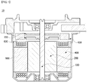
- FIG. 1 is a schematic view of a motor according to a first embodiment
- FIG. 2 is a cross-sectional view of the motor according to the first embodiment
- FIG. 3 is a modification of FIG. 2
- FIG. 4 is an enlarged view of B in FIG. 3
- FIG. 5 is a view for describing an effect of a maximum length of each of sides of a hollow portion
- FIG. 6 is a cross-sectional view taken along line A-A' in FIG. 2
- FIG. 7 is an enlarged view of portion D in FIG. 6
- FIG. 8 is a view illustrating various embodiments of a patterned portion of a rotor
- FIG. 9 is an image illustrating a magnetic analysis distribution of a fourth region in FIG. 6 .
- a motor 10 includes a rotary shaft 100, a rotor 200, a magnet 300, and a stator 400.
- the rotary shaft 100 may be disposed at a center of the motor 10.
- the rotary shaft 100 may be disposed on a central axis C of the motor 10.
- the rotary shaft 100 may be coupled to the rotor 200. More specifically, when an electromagnetic interaction between the rotor 200 and the stator 400 occurs due to supply of currents, the rotor 200 rotates, and thus the rotary shaft 100 may rotate.
- the rotary shaft 100 may rotate with respect to the central axis C to transfer power to an external device.
- the rotary shaft 100 may have a cylindrical shape, and the central axis C may be a straight line which connects centers of circles in the rotary shaft 100.
- the rotary shaft 100 may be surrounded by the rotor 200, the magnet 300, and the stator 400 which will be described later.
- the rotor 200, the magnet 300, and the stator 400 may have a longer separation distance from the central axis C in order of the rotor 200, the magnet 300, and the stator 400. Further, the rotary shaft 100 may pass through the rotor 200, the magnet 300, and the stator 400.
- the rotor 200 causes an electrical interaction with the stator 400 and may rotate through the caused electrical interaction.
- the rotary shaft 100 may also rotate in conjunction with rotation of the rotor 200.
- the rotary shaft 100 may be connected to power bodies of various devices to transmit power to the power bodies.
- the rotary shaft may be connected to a mobile device or a joint part of a robot to adjust a height of the lens to adjust the lens magnification of the mobile device or to rotate an arm or the like of the robot.
- the rotor 200 may be implemented in a shape in which a plurality of plates having a form of a circular thin steel plate are stacked or in a single cylindrical form. Further, a hole to which the rotary shaft 100 is coupled may be disposed in a center of the rotor 200. In addition, the rotary shaft 100 may be inserted into the hole.
- the rotor 200 may include a patterned portion 210 and a rotor core 220.
- the rotor core 220 may include a groove.
- the groove may be formed in an inner surface of the rotor 200. That is, the groove may be disposed at the inside of the rotor core 220.
- the patterned portion 210 may be disposed in the groove. That is, the patterned portion 210 may be disposed adjacent to the rotary shaft 100. The patterned portion 210 may be disposed to come into contact with the rotary shaft 100. Accordingly, the patterned portion 210 may come into contact with the rotary shaft 100.
- the patterned portion 210 may include a plurality of unit patterns and hollow portions disposed in the unit patterns. Further, the hollow portions may include a plurality of hollows. The patterned portion 210 may form a lattice structure due to the plurality of hollows. Accordingly, a lattice structure may be formed adjacent to the through hole in the rotor 200.
- the motor 10 according to the first embodiment has the patterned portion including the hollows located inside the rotor 200 and thus the electrical interaction between the stator 400 and the rotor 200 occurring from an outer side of the rotor 200 may not be hindered.
- the patterned portion 210 includes the hollows, manufacturing costs of the motor 10 according to the embodiment are reduced, the weight of the motor decreases, and the power density of the motor may be improved.
- the power density refers to a size of the motor in comparison with power of the motor, and improvement in the power density means that the motor is reduced in size under the same power (torque).
- the rotor core 220 may be disposed at the outer side of the rotor 200. Further, as a modification, the groove of the rotor core 220 may be a hollow.
- the magnet 300 may be disposed on an outer circumferential surface or at the outer side of the rotor 200. When the magnet is a surface permanent magnet (SPM) type attached to the outer circumferential surface of the rotor 200, a plurality of magnets may be disposed at a predetermined interval along the outer circumferential surface of the rotor 200. Alternatively, in an interior surface magnet (IPM) type in which magnets are buried into the rotor 200, a plurality of magnets may be buried at a predetermined interval in the rotor 200.
- the rotor 200 may include a can member (not shown). The can member (not shown) fixes the magnets to prevent separation of the magnets from the rotor and prevents exposure of the magnets by surrounding the magnets.
- the magnet 300 may be disposed on the rotor core 220.
- a molding part may be disposed to surround the magnet 300 and the rotor core 220, and the molding part may couple the magnet 300 and the rotor core 220.
- the molding part may be formed by double injection in a state of including the rotor core 220 and the magnet. Further, the molding part may be formed to surround only some of an inner circumferential surface of the magnet 300 with respect to a direction of the central axis C but is not limited thereto.
- the magnet 300 may be disposed on the rotor core 220 to have a concentric axis with the rotor core 220.
- the magnet 300 may be coupled to an outer circumferential surface of the rotor core 220.
- the magnet 300 may be magnetized into a plurality of poles.
- the magnet 300 may be concentrically disposed with the central axis C. Accordingly, the magnet 300 and the rotor 200 may have the same central axis C.
- the magnet 300 may cause signals for detecting a rotating position of the rotor core 220.
- the magnet 300 may be implemented in a ring shape.
- the magnet 300 may include a hole through which the rotary shaft 100 passes in a center thereof.
- the stator 400 may include a stator core including a plurality of teeth.
- the stator core may be provided with a ringshaped yoke portion, and the teeth on which the coil is wound in a center direction may be provided along the yoke.
- the teeth may be provided at a predetermined interval along an outer circumferential surface of the yoke portion.
- a plurality of plates each formed as a thin steel plate may be stacked to form the stator core.
- a plurality of divided cores may be coupled or connected to each other to form the stator core.
- stator 400 may include a through hole into which the rotary shaft 100, the rotor 200, and the magnet 300 are inserted.
- the stator 400 may have the greatest diameter in comparison with the rotary shaft 100, the rotor 200, and the magnet 300 with respect to the central axis C.
- the motor 10 may include a bus bar 450.
- the bus bar 450 may be disposed on the stator 400.
- the bus bar 450 may include a terminal in a ringshaped mold member.
- a housing 900 of the motor 10 may accommodate the rotor 200 and the stator 400 therein.
- the housing 900 may include a body and a bracket.
- the body has a cylindrical shape.
- the body may be formed of a metal material such as aluminum. Further, an upper portion of the body is opened.
- the bracket covers the opened upper portion of the body.
- the stator 400 is disposed at an inner side of the body, and the rotor 200 may be disposed at an inner side of the stator 400.
- Bearings may be disposed at a center portion of the bracket. The bearings may be integrated with the bracket by double injection.
- a sensing magnet 600 is an apparatus coupled to the rotary shaft 100 to be linked to the rotor 200 to detect a position of the rotor 200.
- a sensor which senses a magnetic force of the sensing magnet 600 may be disposed in a printed circuit board 700.
- the sensor may be a Hall IC.
- the sensor senses a change in the N pole and the S pole of the sensing magnet 600 to generate sensing signals.
- the patterned portion 210 may be disposed in the rotor core 220.
- a portion of an inner side surface of the rotor core 220 may come into contact with the rotary shaft 100. That is, the rotor core 220 may be disposed to surround the patterned portion 210. Accordingly, since the patterned portion 210 does not come into contact with the rotary shaft 100, and the inner side surface of the rotor core 220 comes into contact with the rotary shaft 100, a coupling force between the rotary shaft 100 and the rotor 200 may be improved.
- the patterned portion 210 may include a plurality of hollows. Further, the hollow may include a plurality of sides. Specifically, the patterned portion 210 may include a first frame disposed to be elongated in a direction of the rotation axis (X-axis direction) and a second frame disposed in a direction perpendicular to the direction of the rotation axis (Y-axis direction). The first frame may have a length in the X-axis direction greater than a length of the second frame in the Y-axis direction.
- an interval between facing sides among the plurality of sides may be greater than a minimum interval between the plurality of hollows.
- a maximum length W2 of each of the plurality of sides may be 1 mm to 1.75 mm.
- the power density may be improved without degradation of an electromagnetic action between the stator and the rotor.
- the interval between the hollows may be a length in a first direction (the X-axis direction) or a second direction (the Y-axis direction).
- the maximum length of each of the plurality of sides may be a length in the second direction (the Y-axis direction).
- the first direction (the X-axis direction) may be the same as the direction of the central axis C
- the second direction (the Y-axis direction) may be a direction perpendicular to the direction of the central axis C.
- the thickness of the patterned portion was 0.5 times the thickness of the rotor and was disposed to come into contact with an inner side of the rotor.
- the thickness refers to a length in a direction perpendicular to the central axis C.
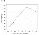
- the strength according to the length of the pattern side is shown as a graph.
- Table 1 and FIG. 3 when the patterned portion was not present (Comparative Example), or the length of the pattern side was 0.25 mm (Experimental Example 1), it was shown that the strength was the same as 165 MPa. Further, it was shown that when the length of the pattern side was 0.50 mm (Experimental Example 2), the strength was 172 MPa, and when the length of the pattern side was 0.75 mm (Experimental Example 3), the strength was 183 MPa.
- the patterned portion of the motor according to the embodiment may provide improved strength.
- the thickness refers to a length in a direction perpendicular to the central axis C.
- each torque was similar at 6.4 Nm, 6.4 Nm, 6.5 Nm, and 6.5 Nm, but each power density was 61.10 W/mm 3 , 61.72 W/mm 3 , 62.40 W/mm 3 , and 62.99 W/mm 3 . That is, since an area of the hollow increases when the length of the pattern side increases, a volume of the hollow in comparison with an entire volume of the motor increases and thus the power density may be improved. As described above, since the hollow is formed through the patterned portion, the motor according to the embodiment may provide the effect that the power density is improved.
- the patterned portion 210 of the rotor 200 may be disposed at an outer side of the rotary shaft 100, the rotor core 220 may surround the outer side of the patterned portion 210, and the magnet may be disposed at the outer side of the rotor core 220. Further, the stator 400 may be disposed to be spaced apart from an outer side of the magnet 300 and to surround the rotary shaft 100, the rotor 200, and the magnet 300.
- the central axis C may be disposed at centers of the rotary shaft 100, the rotor 200, the magnet 300, and the stator 400.
- a diameter R1 of the rotary shaft 100 may be 2 mm to 3 mm with respect to the central axis C.
- the diameter is not limited thereto, and the diameter may be variously changed according to the size of the motor.
- a diameter R2 of the patterned portion 210 may be 4 mm to 6 mm with respect to the central axis C. However, as described above, the diameter may be variously changed according to the size of the motor. Further, a diameter R3 of the rotor 200 (or the rotor core 220) may be 6 mm to 9 mm.
- a diameter ratio between the diameter of the rotor core (or an outer contour portion which will be described later) from the rotary shaft and the diameter of the patterned portion from the rotary shaft may be smaller than or equal to 1:0.5.
- the torque ripple refers to deviation of the torque as a fluctuation range of the torque.
- the torque ripple becomes smaller than 0.150 Nm when the diameter ratio is smaller than 0.5, the fluctuation range of the torque provided by the motor decreases and thus the lifespan of the motor may be increased and an error of power which is provided may be reduced.
- the fluctuation range of the torque may increase.
- the patterned portion may have various shapes.
- the patterned portion may have a frame in a direction inclined on the basis of the central axis C, and as shown in FIG. 8B , the patterned portion may include a honeycomb-shaped hollow (or an opening) shape.
- the patterned portion may be alternately disposed in a direction in which the hollow is perpendicular to the central axis C, such as a brick shape.
- the patterned portion may have various shapes each including a hollow, and the power density may be improved through a structure of expanding the area of the hollow portion.
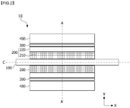
- FIG. 10 is a side cross-sectional view of a motor according to a second embodiment
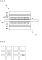
- FIG. 11 is a cross-sectional view taken along line B-B' of the motor in FIG. 10
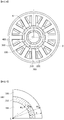
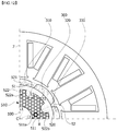
- FIG. 12 is an enlarged view of a seventh region in FIG. 11
- FIG. 13 is an enlarged view of an eighth region in FIG. 12 .
- a motor 20 according to the second embodiment of the present invention is the same as the motor shown in FIG. 2 and overlapping configurations will be described using the same reference numerals.
- the motor 20 includes a rotary shaft 100, a rotor 500, a magnet 300, and a stator 400.
- the rotor 500 and the stator 400 may electrically interact. When the electrical interaction is caused, the rotor 500 may rotate.
- the rotary shaft 100 may also rotate in conjunction with rotation of the rotor 500.
- the rotary shaft 100 may be connected to power bodies of various devices to transmit power to the power bodies.
- the rotary shaft 100 may be surrounded by the rotor 500, the magnet 300, and the stator 400.
- the rotor 500, the magnet 300, and the stator 400 may have a long separation distance from the central axis C in order of the rotor 500, the magnet 300, and the stator 400. Further, the rotary shaft 100 may pass through the rotor 500, the magnet 300, and the stator 400.
- the rotor 500 may come into contact with the rotary shaft 100 and may be disposed to surround the rotary shaft 100.
- the rotor 500 may be integrally formed with the rotary shaft 100 or may include a first through hole through which the rotary shaft 100 passes. Further, the rotary shaft 100 may be inserted into the first through hole.
- the rotor 500 may include a patterned portion 510 and an outer contour portion 520.
- the outer contour portion 520 may correspond to or include the above-described rotor core.
- the rotor 500 may be implemented in a power bed fusion (PBF) manner among metal three-dimensional (3D) printing technologies.
- PPF power bed fusion
- the patterned portion 510 may include a plurality of unit patterns 511, and each of the plurality of unit patterns 511 may be formed in an angular or circular pattern having a hollow portion 511a. That is, the patterned portion 510 may form a lattice structure or honeycomb structure.
- the patterned portion 510 may be exposed to the outside.
- the patterned portion 510 may not be exposed to the outside and may be formed only in the rotor 500. The above will be described later.
- the motor 20 according to the embodiment has the patterned portion 510 including a plurality of hollow portions 511a located inside the rotor 500, and thus the electrical interaction between the stator 400 and the rotor 500 occurring from an outer side of the rotor 500 may not be hindered.
- the patterned portion 510 includes the hollow portions 511a, manufacturing costs of the motor 20 according to the second embodiment are reduced, the weight of the motor decreases, and the power density of the motor may be improved.
- the power density refers to a size of the motor in comparison with power of the motor, and improvement in the power density means that the motor is reduced in size under the same power (torque).
- the first through hole may be formed in a central axis of the patterned portion 510.
- the patterned portion 510 may be disposed adjacent to the rotary shaft 100, and the patterned portion 510 may be disposed to come into contact with the rotary shaft 100.
- FIG. 14 is a side cross-sectional view of a motor according to a third embodiment of the present invention.
- a non-pattern rotor core portion 530 in which a pattern is not formed may be disposed between a patterned portion 510 and a rotary shaft 100.
- a jig hole (not shown) on which a jig for assembly is seated may be formed in the patterned portion 510.
- the outer contour portion 520 forms the outermost contour of a rotor 500 and includes an outer circumferential surface 521 and an inner circumferential surface 522.
- the outer circumferential surface 521 faces a stator 400, and the inner circumferential surface 522 faces a central axis C.
- a plurality of magnets 300 are disposed on the outer circumferential surface 521, and a plurality of protrusion portions 522a and 522b protrude toward the central axis C from the inner circumferential surface 522.
- guide protrusions which guide disposition of the plurality of magnets 300 may be formed on the outer circumferential surface 521.
- the plurality of magnets 300 may include a first magnet 310, a second magnet 320, and a third magnet 330 disposed to be adjacent to and spaced apart from each other along the outer circumferential surface 521 of the outer contour portion 520.
- the first magnet 310 and the second magnet 320 may be spaced apart from each other on the outer circumferential surface 521 of the outer contour portion 520 to form a first separation portion S1. Further, the second magnet 320 and the third magnet 330 may be spaced apart from each other on the outer circumferential surface 521 of the outer contour portion 520 to form a second separation portion S2.
- the first separation portion S1 may have a predetermined area through a virtual straight line which connects upper portions of the first magnet 310 and the second magnet 320.
- the second separation portion S2 may have a predetermined area through a virtual straight line which connects upper portions of the second magnet 320 and the third magnet 330.
- first separation portion S1 and the second separation portion S2 may have the same area.
- the plurality of protrusion portions 522a and 522b may include a first protrusion portion 522a and a second protrusion portion 522b disposed to be adjacent to and spaced apart from each other along the inner circumferential surface 522 of the outer contour portion 520.
- Each of the first protrusion portion 522a and the second protrusion portion 522b is formed to protrude in a first direction which extends toward the central axis C of the rotor 500 from the inner circumferential surface 522 of the outer contour portion 520.
- all of the outer contour portion 520 and the first protrusion portion 522a and the second protrusion portion 522b may be integrally composed.
- a thickness of the outer contour portion 520 may be formed to be greater in comparison with an area in which the first protrusion portion 522a and the second protrusion portion 522b are not formed.
- a width of the first protrusion portion 522a or the second protrusion portion 522b in a second direction which is perpendicular to the first direction may be gradually or gradationally decreased in a direction closer to the central axis C of the rotor 500.
- an area ratio of the patterned portion 510 may be maximized at the inside of the rotor 500 to reduce the weight, and an area ratio of the outer contour portion 520 may be increased at the outside of the rotor 500 to decrease the structural strength and magnetic resistance.
- first protrusion portion 522a may be disposed in a virtual straight line L1 which connects the central axis C of the rotor 500 and a center of the first separation portion S1
- second protrusion portion 522b may be disposed in in a virtual straight line L2 which connects the central axis C of the rotor 500 and a center of the second separation portion S2.
- an area of the first protrusion portion 522a may be formed to be 110% to 350% of an area of the first separation portion S1.
- an area of the second protrusion portion 522b may be formed to be 110% to 350% of an area of the second separation portion S2
- the area of the first protrusion portion 522a is formed to be smaller than or equal to 110% of the area of the first separation portion S1
- the magnetic resistance increases in the outer contour portion 520 of the rotor 500 corresponding to the first separation portion S1 in which the magnets 300 are not disposed due to a magnetic saturation phenomenon, a problem that the performance of the motor 20 is reduced is difficult to prevent.
- the area of the first protrusion portion 522a is formed to be greater than or equal to 350% of the area of the first separation portion S1
- the thickness and area of the outer contour portion 520 in which the first protrusion portion 522a is formed increase excessively, there is a problem in that the weight reduction of the motor 20 may not be maintained.
- the outer contour portion 520 may have a first thickness T1
- the first protrusion portion 522a may have a second thickness T2
- the first thickness T1 may be formed to be 80% to 110% of the second thickness T2.
- the first thickness T1 of the outer contour portion 520 is set to be smaller than or equal to 80% of the second thickness T2 of the first protrusion portion 522a, since the magnetic resistance increases in the outer contour portion 520 of the rotor 500 corresponding to the first separation portion S1 in which the magnets 300 are not disposed due to the magnetic saturation phenomenon, the problem that the performance of the motor 20 is reduced is difficult to prevent.
- first thickness T1 of the outer contour portion 520 is set to be greater than or equal to 110% of the second thickness T2 of the first protrusion portion 522a, since the thickness and area of the outer contour portion 520 in which the first protrusion portion 522a is formed increase excessively, there is a problem in that the weight reduction of the motor 20 may not be maintained.
- the plurality of unit patterns 511 of the patterned portion 510 may be disposed between the first protrusion portion 522a and the second protrusion portion 522b.
- the plurality of unit patterns 511 may be disposed between the central axis C of the rotor 500 and the first protrusion portion 522a.
- the plurality of unit patterns 511 may be disposed between the central axis C of the rotor 500 and the second protrusion portion 522b.
- the rotor 500 may be lightened.
- maximum lengths W3 and W4 of the unit patterns 511 among lengths which are measured in various directions may be roughly set to 0.5 mm to 5 mm
- the maximum length W3 of the unit pattern 511 may be formed to be 5% to 50% of a maximum length D1 of lengths D of the first protrusion portion 522a or second protrusion portion 522b which are measured in various directions
- structural reliability of the rotor 500 may be secured through a honeycomb structure formed by the plurality of unit patterns 511 disposed to surround the first protrusion portion 522a and the second protrusion portion 522b.
- the magnets 300 may be disposed on the outer circumferential surface 521 of the outer contour portion 520 of the rotor 500.
- the magnets 300 may be magnetized into a plurality of poles.
- the magnets 300 may cause signals for detecting a rotating position of the rotor 500.
- the magnet 300 may be implemented in a ring shape.
- the stator 400 may include a second through hole into which the rotary shaft 100, the rotor 500, and the magnets 300 are inserted.
- the rotary shaft 100, the rotor 500, and the magnets 300 may be disposed in the second through hole of the stator 400.
- the stator 400 may have the greatest diameter in comparison with the rotary shaft 100, the rotor 500, and the magnets 300 with respect to the central axis C.
Landscapes
- Engineering & Computer Science (AREA)
- Power Engineering (AREA)
- Iron Core Of Rotating Electric Machines (AREA)
- Permanent Field Magnets Of Synchronous Machinery (AREA)
Abstract
Description
- The present invention relates to a motor.
- Generally, in the motor, a rotor rotates due to an electromagnetic interaction between the rotor and a stator. In this case, a rotary shaft inserted into the rotor also rotates to generate a rotational driving force.
- Further, lately, the motor is being used in automobiles, home appliances, robots, and the like and demand is rapidly increasing. However, the rotor may have a form in which metal plates are simply laminated in an axial direction in which the rotation shaft rotates. Accordingly, the rotor is formed of the metal plates even in a portion which is not electromagnetically affected and thus there is problem that a weight of the rotor is increased.
- Further, the motor has a limit in that the power density is lowered due to the weight of the rotor.
- An embodiment of the present invention is directed to providing a lightweight motor.
- Further, an embodiment of the present invention is directed to providing a motor of which power density is improved.
- In addition, an embodiment of the present invention is directed to providing a motor which prevents torque reduction.
- In addition, an embodiment of the present invention is directed to providing a motor in which durability is improved by securing structural strength in the outside of the rotor.
- Problems to be solved by the present invention are not limited to the above-described problems, and purposes and effects understood from solutions and embodiments which will be described below are also included.
- One aspect of the present invention provides a motor including a stator including a through hole, a cylindrical rotor disposed in the through hole, a rotor center axis formed in a central region of the rotor and to which a rotary shaft is coupled, and a first magnet and a second magnet disposed between the stator and the rotor, wherein the rotor includes an outer contour portion and a patterned portion disposed between the outer contour portion and the center axis of the rotor, the patterned portion includes a plurality of unit patterns and a hollow portion disposed in each of the unit patterns, the outer contour portion includes an outer circumferential surface on which the first magnet and the second magnet are disposed and an inner circumferential surface which comes in contact with the plurality of unit patterns, the inner circumferential surface of the outer contour portion further includes a first protrusion portion protruding in a first direction which is a direction toward the rotor center axis, and a maximum length of the first protrusion portion in the first direction is greater than a maximum length of each of the unit patterns.
- A first separation portion formed as a space between the first magnet and the second magnet may be further included on the outer circumferential surface of the outer contour portion.
- The first protrusion portion may be disposed in a virtual straight line which connects the central axis and a center of the first separation portion.
- The plurality of unit patterns of the patterned portion may be disposed in the virtual straight line which connects the central axis and the center of the first separation portion.
- The inner circumferential surface of the outer contour portion may further include a second protrusion portion which is spaced apart from the first protrusion portion and protrudes in the first direction.
- The motor may further include a third magnet disposed between the stator and the rotor, and the third magnet may be adjacent to the second magnet.
- The motor may further include a second separation portion formed as a space between the second magnet and the third magnet, and the second protrusion portion may be disposed in a virtual straight line which connects the central axis and a center of the second separation portion.
- The plurality of unit patterns of the patterned portion may be disposed in the virtual straight line which connects the central axis and the center of the second separation portion.
- A size of a cross section of one of the first protrusion portion and the second protrusion portion may be 110% to 350% of a size of a cross section of one of the first separation portion and the second separation portion.
- A width of one of the first protrusion portion and the second protrusion portion in a second direction which is perpendicular to the first direction may be decreased in a direction closer to the central axis.
- The outer contour portion may have a first thickness in the first direction, one of the first protrusion portion and the second protrusion portion in the first direction may have a second thickness, and the first thickness may be smaller than the second thickness.
- The first thickness may be 80% to 110% of the second thickness.
- The patterned portion may be exposed to the outside of the rotor.
- Meanwhile, another aspect of the present invention provides a motor including a stator including a through hole, a cylindrical rotor disposed in the through hole, a rotor center axis formed in a central region of the rotor and to which a rotary shaft is coupled, and a first magnet, a second magnet, and a third magnet disposed between the stator and the rotor, wherein the rotor includes an outer contour portion and a patterned portion disposed between the outer contour portion and the center axis of the rotor, the patterned portion includes a plurality of unit patterns and a hollow portion disposed in each of the unit patterns, the outer contour portion includes an outer circumferential surface on which the first magnet, the second magnet, and the third magnet are disposed and an inner circumferential surface which comes in contact with the plurality of unit patterns, the inner circumferential surface of the outer contour portion further includes a first protrusion portion protruding in a first direction which is a direction toward the rotor center axis and a second protrusion portion which is disposed adjacent to the first protrusion portion and protrudes in the first direction, and the plurality of unit patterns of the patterned portion are disposed between the first protrusion portion and the second protrusion portion.
- The motor may further include a first separation portion formed as a space between the first magnet and the second magnet, and the first protrusion portion may be disposed in a virtual straight line which connects the central axis and a center of the first separation portion.
- The plurality of unit patterns of the patterned portion may be disposed in the virtual straight line which connects the central axis and the center of the first separation portion.
- The motor may further include a second separation portion formed as a space between the second magnet and the third magnet, and the second protrusion portion may be disposed in a virtual straight line which connects the central axis and a center of the second separation portion.
- The plurality of unit patterns of the patterned portion may be disposed in the virtual straight line which connects the central axis and the center of the second separation portion.
- A width of one of the first protrusion portion and the second protrusion portion in a second direction which is perpendicular to the first direction may be decreased in a direction closer to the central axis.
- The patterned portion may be exposed to the outside of the rotor.
- Still another aspect of the present invention provides a motor including a rotary shaft, a stator including a hole through which the rotary shaft passes, a rotor disposed in the stator, and a magnet disposed between the rotor and the stator, wherein the rotor includes a rotor core including a groove, a patterned portion disposed in the groove and including a plurality of openings, and the groove is disposed in the rotor.
- The patterned portion may come into contact with the rotary shaft.
- A diameter ratio between a diameter of the rotor core from the rotary shaft and a diameter of the patterned portion from the rotary shaft may be smaller than 1:0.5.
- The opening may include a plurality of sides, and a maximum length of each of the plurality of sides is 1 mm to 1.75 mm.
- The patterned portion may include a first frame disposed in a direction of the rotary shaft and a second frame disposed in a direction perpendicular to the direction of the rotary shaft.
- An interval between facing sides among the plurality of sides may be greater than a minimum interval between the plurality of openings.
- The magnet may be disposed at an outer side of the rotor core.
- According to an embodiment of the present invention, a motor of which power density is improved can be implemented.
- Further, according to the embodiment of the present invention, a motor which prevents torque reduction can be implemented.
- In addition, according to the embodiment of the present invention, a motor in which durability is improved by securing structural strength in the outside of a rotor can be implemented.
- Various useful advantages and effects of the present invention are not limited to the above and may be relatively easily understood in a process of describing exemplary embodiments of the present invention.
-
-
FIG. 1 is a schematic view of a motor according to a first embodiment. -
FIG. 2 is a cross-sectional view of the motor according to the first embodiment. -
FIG. 3 is a modification ofFIG. 2 . -
FIG. 4 is an enlarged view of B inFIG. 3 . -
FIG. 5 is a view for describing an effect of a maximum length of each of sides of a hollow portion. -
FIG. 6 is a cross-sectional view taken along line A-A' inFIG. 2 . -
FIG. 7 is an enlarged view of portion D inFIG. 6 . -
FIG. 8 is a view illustrating various embodiments of a patterned portion of a rotor. -
FIG. 9 is an image illustrating a magnetic analysis distribution of a fourth region inFIG. 6 . -
FIG. 10 is a side cross-sectional view of a motor according to a second embodiment of the present invention. -
FIG. 11 is a cross-sectional view taken along line B-B' of the motor inFIG. 10 . -
FIG. 12 is an enlarged view of a seventh region inFIG. 11 . -
FIG. 13 is an enlarged view of an eighth region inFIG. 12 . -
FIG. 14 is a side cross-sectional view of a motor according to a third embodiment of the present invention. - Since the present invention may be variously changed and have various embodiments, particular embodiments will be exemplified and described in the drawings. However, the present invention is not limited to the particular embodiments and includes all changes, equivalents, and substitutes within the spirit and the scope of the present invention.
- Further, it should be understood that, although the terms "second," "first," and the like may be used herein to describe various elements, the elements are not limited by the terms. The terms are only used to distinguish one element from another. For example, a first element could be termed a second element, and similarly, a second element could be termed a first element without departing from the scope of the present invention. The term "and/or" includes any one or any combination among a plurality of associated listed items.
- When predetermined components are mentioned as being "linked," or "connected" to other components, the components may be directly linked or connected to other components, but it should be understood that additional components may be present therebetween. On the other hand, when the predetermined components are mentioned as being "directly linked," or "directly connected" to other components, it should be understood that no additional components are present between the above-described components.
- Terms used in the present invention are used solely to describe the particular embodiments and not to limit the present invention. The singular form is intended to also include the plural form, unless the context clearly indicates otherwise. It should be further understood that the terms "include," "including," "provide," "providing," "have," and/or "having" specify the presence of stated features, integers, steps, operations, elements, components, and/or groups thereof but do not preclude the presence or addition of one or more other features, integers, steps, operations, elements, components, and/or groups thereof.
- Unless otherwise defined, all terms including technical or scientific terms used in the present invention have meanings which are the same as those of terms generally understood by those skilled in the art. It will be further understood that terms, such as those defined in commonly used dictionaries, should be interpreted as having a meaning that is consistent with their meaning in the context of the relevant art and will not be interpreted in an idealized or overly formal sense unless expressly so defined herein.
- Hereinafter, the embodiments will be described in detail with reference to the accompanying drawing drawings, the same reference numerals are applied to the same or corresponding elements regardless of the reference numerals, and redundant description thereof will be omitted.
-
FIG. 1 is a schematic view of a motor according to a first embodiment,FIG. 2 is a cross-sectional view of the motor according to the first embodiment,FIG. 3 is a modification ofFIG. 2 ,FIG. 4 is an enlarged view of B inFIG. 3 ,FIG. 5 is a view for describing an effect of a maximum length of each of sides of a hollow portion,FIG. 6 is a cross-sectional view taken along line A-A' inFIG. 2 ,FIG. 7 is an enlarged view of portion D inFIG. 6 ,FIG. 8 is a view illustrating various embodiments of a patterned portion of a rotor, andFIG. 9 is an image illustrating a magnetic analysis distribution of a fourth region inFIG. 6 . - Referring to
FIGS. 1 and2 , amotor 10 according to the first embodiment includes arotary shaft 100, arotor 200, amagnet 300, and astator 400. First, therotary shaft 100 may be disposed at a center of themotor 10. For example, therotary shaft 100 may be disposed on a central axis C of themotor 10. Further, therotary shaft 100 may be coupled to therotor 200. More specifically, when an electromagnetic interaction between therotor 200 and thestator 400 occurs due to supply of currents, therotor 200 rotates, and thus therotary shaft 100 may rotate. In this case, therotary shaft 100 may rotate with respect to the central axis C to transfer power to an external device. Further, therotary shaft 100 may have a cylindrical shape, and the central axis C may be a straight line which connects centers of circles in therotary shaft 100. - The
rotary shaft 100 may be surrounded by therotor 200, themagnet 300, and thestator 400 which will be described later. Therotor 200, themagnet 300, and thestator 400 may have a longer separation distance from the central axis C in order of therotor 200, themagnet 300, and thestator 400. Further, therotary shaft 100 may pass through therotor 200, themagnet 300, and thestator 400. - The
rotor 200 causes an electrical interaction with thestator 400 and may rotate through the caused electrical interaction. Therotary shaft 100 may also rotate in conjunction with rotation of therotor 200. Therotary shaft 100 may be connected to power bodies of various devices to transmit power to the power bodies. For example, the rotary shaft may be connected to a mobile device or a joint part of a robot to adjust a height of the lens to adjust the lens magnification of the mobile device or to rotate an arm or the like of the robot. - Meanwhile, the
rotor 200 may be implemented in a shape in which a plurality of plates having a form of a circular thin steel plate are stacked or in a single cylindrical form. Further, a hole to which therotary shaft 100 is coupled may be disposed in a center of therotor 200. In addition, therotary shaft 100 may be inserted into the hole. - The
rotor 200 may include a patternedportion 210 and arotor core 220. - First, the
rotor core 220 may include a groove. The groove may be formed in an inner surface of therotor 200. That is, the groove may be disposed at the inside of therotor core 220. - The patterned
portion 210 may be disposed in the groove. That is, the patternedportion 210 may be disposed adjacent to therotary shaft 100. The patternedportion 210 may be disposed to come into contact with therotary shaft 100. Accordingly, the patternedportion 210 may come into contact with therotary shaft 100. - Further, the patterned
portion 210 may include a plurality of unit patterns and hollow portions disposed in the unit patterns. Further, the hollow portions may include a plurality of hollows. The patternedportion 210 may form a lattice structure due to the plurality of hollows. Accordingly, a lattice structure may be formed adjacent to the through hole in therotor 200. By such a configuration, themotor 10 according to the first embodiment has the patterned portion including the hollows located inside therotor 200 and thus the electrical interaction between thestator 400 and therotor 200 occurring from an outer side of therotor 200 may not be hindered. Further, since the patternedportion 210 includes the hollows, manufacturing costs of themotor 10 according to the embodiment are reduced, the weight of the motor decreases, and the power density of the motor may be improved. Here, the power density refers to a size of the motor in comparison with power of the motor, and improvement in the power density means that the motor is reduced in size under the same power (torque). - The
rotor core 220 may be disposed at the outer side of therotor 200. Further, as a modification, the groove of therotor core 220 may be a hollow. Themagnet 300 may be disposed on an outer circumferential surface or at the outer side of therotor 200. When the magnet is a surface permanent magnet (SPM) type attached to the outer circumferential surface of therotor 200, a plurality of magnets may be disposed at a predetermined interval along the outer circumferential surface of therotor 200. Alternatively, in an interior surface magnet (IPM) type in which magnets are buried into therotor 200, a plurality of magnets may be buried at a predetermined interval in therotor 200. Further, therotor 200 may include a can member (not shown). The can member (not shown) fixes the magnets to prevent separation of the magnets from the rotor and prevents exposure of the magnets by surrounding the magnets. - For example, the
magnet 300 may be disposed on therotor core 220. Further, a molding part may be disposed to surround themagnet 300 and therotor core 220, and the molding part may couple themagnet 300 and therotor core 220. For example, the molding part may be formed by double injection in a state of including therotor core 220 and the magnet. Further, the molding part may be formed to surround only some of an inner circumferential surface of themagnet 300 with respect to a direction of the central axis C but is not limited thereto. Themagnet 300 may be disposed on therotor core 220 to have a concentric axis with therotor core 220. Themagnet 300 may be coupled to an outer circumferential surface of therotor core 220. - Further, the
magnet 300 may be magnetized into a plurality of poles. Themagnet 300 may be concentrically disposed with the central axis C. Accordingly, themagnet 300 and therotor 200 may have the same central axis C. Themagnet 300 may cause signals for detecting a rotating position of therotor core 220. Further, themagnet 300 may be implemented in a ring shape. Themagnet 300 may include a hole through which therotary shaft 100 passes in a center thereof. - A coil may be wound around the
stator 400 to cause the electrical interaction between thestator 400 and therotor 200. A specific configuration of thestator 400 for winding the coil will be described later. Thestator 400 may include a stator core including a plurality of teeth. The stator core may be provided with a ringshaped yoke portion, and the teeth on which the coil is wound in a center direction may be provided along the yoke. The teeth may be provided at a predetermined interval along an outer circumferential surface of the yoke portion. Meanwhile, a plurality of plates each formed as a thin steel plate may be stacked to form the stator core. Further, a plurality of divided cores may be coupled or connected to each other to form the stator core. In addition, thestator 400 may include a through hole into which therotary shaft 100, therotor 200, and themagnet 300 are inserted. Thestator 400 may have the greatest diameter in comparison with therotary shaft 100, therotor 200, and themagnet 300 with respect to the central axis C. - Further, the
motor 10 may include abus bar 450. Thebus bar 450 may be disposed on thestator 400. Thebus bar 450 may include a terminal in a ringshaped mold member. - A
housing 900 of themotor 10 may accommodate therotor 200 and thestator 400 therein. Thehousing 900 may include a body and a bracket. The body has a cylindrical shape. The body may be formed of a metal material such as aluminum. Further, an upper portion of the body is opened. The bracket covers the opened upper portion of the body. Thestator 400 is disposed at an inner side of the body, and therotor 200 may be disposed at an inner side of thestator 400. Bearings may be disposed at a center portion of the bracket. The bearings may be integrated with the bracket by double injection. - A
sensing magnet 600 is an apparatus coupled to therotary shaft 100 to be linked to therotor 200 to detect a position of therotor 200. - A sensor which senses a magnetic force of the
sensing magnet 600 may be disposed in a printedcircuit board 700. In this case, the sensor may be a Hall IC. The sensor senses a change in the N pole and the S pole of thesensing magnet 600 to generate sensing signals. - Referring to
FIG. 3 , in a motor 10' according to the modification, the patternedportion 210 may be disposed in therotor core 220. In this case, a portion of an inner side surface of therotor core 220 may come into contact with therotary shaft 100. That is, therotor core 220 may be disposed to surround the patternedportion 210. Accordingly, since the patternedportion 210 does not come into contact with therotary shaft 100, and the inner side surface of therotor core 220 comes into contact with therotary shaft 100, a coupling force between therotary shaft 100 and therotor 200 may be improved. - Referring to
FIG. 4 , as described above, the patternedportion 210 may include a plurality of hollows. Further, the hollow may include a plurality of sides. Specifically, the patternedportion 210 may include a first frame disposed to be elongated in a direction of the rotation axis (X-axis direction) and a second frame disposed in a direction perpendicular to the direction of the rotation axis (Y-axis direction). The first frame may have a length in the X-axis direction greater than a length of the second frame in the Y-axis direction. - Further, in the hollow, an interval between facing sides among the plurality of sides may be greater than a minimum interval between the plurality of hollows. By such a configuration, since areas of the hollow portions opened in an entire area of the patterned portion increase, the power density may be improved.
- Further, a maximum length W2 of each of the plurality of sides may be 1 mm to 1.75 mm. By such a configuration, in the motor according to the embodiment, the power density may be improved without degradation of an electromagnetic action between the stator and the rotor. Here, the interval between the hollows may be a length in a first direction (the X-axis direction) or a second direction (the Y-axis direction). Further, the maximum length of each of the plurality of sides may be a length in the second direction (the Y-axis direction). In addition, the first direction (the X-axis direction) may be the same as the direction of the central axis C, and the second direction (the Y-axis direction) may be a direction perpendicular to the direction of the central axis C.
- Referring to Table 1 below, in the case in which the patterned portion was not present (Comparative Example), strength MPa generated from the motor when a length of a pattern side (the maximum length of each of the plurality of sides in the hollow) was adjusted to 0.25 mm (Experimental Example 1), 0.50 mm (Experimental Example 2), 0.75 mm (Experimental Example 3), 1.00 mm (Embodiment 1), 1.25 mm (Embodiment 2), 1.50 mm (Embodiment 3), and 1.75 mm (Embodiment 4) was measured. In this case, an interval W1 between a plurality of patterns was set to 0.25 mm. Further, the thickness of the patterned portion was 0.5 times the thickness of the rotor and was disposed to come into contact with an inner side of the rotor. Here, the thickness refers to a length in a direction perpendicular to the central axis C.
[Table 1] Length of pattern side [mm] Strength [MPa] Comparative Example 165 Experimental Example 1 0.25 165 Experimental Example 2 0.50 172 Experimental Example 3 0.75 183 Embodiment 1 1.00 190 Embodiment 2 1.25 198 Embodiment 3 1.50 195 Embodiment 41.75 191 - Further, referring to
FIG. 5 , in Table 1, the strength according to the length of the pattern side is shown as a graph. Referring to Table 1 andFIG. 3 , when the patterned portion was not present (Comparative Example), or the length of the pattern side was 0.25 mm (Experimental Example 1), it was shown that the strength was the same as 165 MPa. Further, it was shown that when the length of the pattern side was 0.50 mm (Experimental Example 2), the strength was 172 MPa, and when the length of the pattern side was 0.75 mm (Experimental Example 3), the strength was 183 MPa. On the other hand, it was shown that when the length of the pattern side was 1.00 mm (Embodiment 1), the strength was 190 MPa, when the length of the pattern side was 1.25 mm (Embodiment 2), the strength was 198 MPa, when the length of the pattern side was 1.50 mm (Embodiment 3), the strength is 195 MPa, and when the length of the pattern side was 1.75 mm (Embodiment 4), the strength was 191 MPa. - As described above, when the maximum length W2 of each of the plurality of sides is 1 mm to 1.75 mm, the patterned portion of the motor according to the embodiment may provide improved strength.
- Further, referring to Table 2 below, in the case in which the patterned portion was not present (Comparative Example), torque Nm and power density W/mm3 generated from the motor when a length of a pattern side (the maximum length of each of the plurality of sides in the hollow) was adjusted to 1 mm (Embodiment 1), 2 mm (Experimental Example 4), 3 mm (Experimental Example 5), 4 mm (Experimental Example 6), and 5 mm (Experimental Example 7) were measured. In this case, an interval W1 between a plurality of patterns was set to 0.25 mm. Further, the thickness of the patterned portion was 0.5 times the thickness of the rotor and was disposed to come into contact with an inner side of the rotor. Here, the thickness refers to a length in a direction perpendicular to the central axis C.
[Table 2] Length of pattern side [mm] Torque [Nm] Power density [W/mm3] Comparative Example 6.5 60.00 Embodiment 1 1 6.4 60.48 Experimental Example 4 2 6.4 61.10 Experimental Example 5 3 6.4 61.72 Experimental Example 6 4 6.5 62.40 Experimental Example 7 5 6.5 62.99 - Referring to Table 2, when the patterned portion was not present (Comparative Example), or the length of the pattern side was 1 mm (Embodiment 1), it was shown that each torque was similar at 6.5 Nm and 6.4 Nm, and each power density was 60 W/mm3 and 60.48 W/mm3. Further, it was shown that when the lengths of the pattern side were 2 mm (Experimental Example 4), 3 mm (Experimental Example 5), 4 mm (Experimental Example 6), and 5 mm (Experimental Example 7) it was shown that each torque was similar at 6.4 Nm, 6.4 Nm, 6.5 Nm, and 6.5 Nm, but each power density was 61.10 W/mm3, 61.72 W/mm3, 62.40 W/mm3, and 62.99 W/mm3. That is, since an area of the hollow increases when the length of the pattern side increases, a volume of the hollow in comparison with an entire volume of the motor increases and thus the power density may be improved. As described above, since the hollow is formed through the patterned portion, the motor according to the embodiment may provide the effect that the power density is improved.
- However, like Table 1, in the patterned portion, when the maximum length W2 of each of the plurality of sides is smaller than 1 mm, there is a limit that the strength and the power density are not significantly improved, and when the maximum length W2 of each of the plurality of sides is greater than 1.75 mm, the power density may increase but there is a limit that the strength is not significantly improved.
- Referring to
FIGS. 6 and 7 , as described above, the patternedportion 210 of therotor 200 may be disposed at an outer side of therotary shaft 100, therotor core 220 may surround the outer side of the patternedportion 210, and the magnet may be disposed at the outer side of therotor core 220. Further, thestator 400 may be disposed to be spaced apart from an outer side of themagnet 300 and to surround therotary shaft 100, therotor 200, and themagnet 300. - Further, as described above, the central axis C may be disposed at centers of the
rotary shaft 100, therotor 200, themagnet 300, and thestator 400. - Further, a diameter R1 of the
rotary shaft 100 may be 2 mm to 3 mm with respect to the central axis C. However, the diameter is not limited thereto, and the diameter may be variously changed according to the size of the motor. - In addition, a diameter R2 of the patterned
portion 210 may be 4 mm to 6 mm with respect to the central axis C. However, as described above, the diameter may be variously changed according to the size of the motor. Further, a diameter R3 of the rotor 200 (or the rotor core 220) may be 6 mm to 9 mm. - In this case, in the motor according to the embodiment, a diameter ratio between the diameter of the rotor core (or an outer contour portion which will be described later) from the rotary shaft and the diameter of the patterned portion from the rotary shaft may be smaller than or equal to 1:0.5.
- Referring to Table 3 below, torque of the motor and torque ripples in the case in which diameter ratios of the diameter of the rotor core from the rotary shaft and the diameter of the patterned portion from the rotary shaft were 1:0.8, 1:0.6, 1:5, 1:0.33, and 1:02 were measured. In this case, the interval W1 between the plurality of patterns was set to 0.25 mm, and the length of each of the plurality of patterns was set to 1 mm.
[Table 3] Diameter ratio Torque [Nm] Torque ripple [Nm] 1:0.8 6.5 0.152 1:0.66 6.5 0.151 1:5 6.5 0.150 1:0.33 6.4 0.147 1:0.2 6.3 0.124 - Referring to Table 3, even when the diameter ratio was changed, it was shown that the torque was similar. However, it was shown that the torque ripple was greater than or equal to 0.150 Nm when the diameter ratio was greater than 1:0.5. Here, the torque ripple refers to deviation of the torque as a fluctuation range of the torque. As described above, since the torque ripple becomes smaller than 0.150 Nm when the diameter ratio is smaller than 0.5, the fluctuation range of the torque provided by the motor decreases and thus the lifespan of the motor may be increased and an error of power which is provided may be reduced.
- That is, when the outer side of the rotor is adjacent to the stator and thus the patterned portion is located at the outer side of the rotor, since a fluctuation in the electrical interaction between the rotor and the stator occurs according to a structure change due to the hollow of the pattern, the fluctuation range of the torque may increase.
- Referring to
FIG. 8 , the patterned portion may have various shapes. Referring toFIG. 8A , the patterned portion may have a frame in a direction inclined on the basis of the central axis C, and as shown inFIG. 8B , the patterned portion may include a honeycomb-shaped hollow (or an opening) shape. In addition, as shown inFIG. 8C , the patterned portion may be alternately disposed in a direction in which the hollow is perpendicular to the central axis C, such as a brick shape. As described above, the patterned portion may have various shapes each including a hollow, and the power density may be improved through a structure of expanding the area of the hollow portion. - However, referring to
FIG. 9 , since a thickness of therotor core 220 is decreased according to formation of the patternedportion 210, and accordingly, a magnetic resistance increases in a separation area A between themagnet 300 and themagnet 300 due to a magnetic saturation phenomenon, the power density of the motor is reduced, and the torque is reduced. -
FIG. 10 is a side cross-sectional view of a motor according to a second embodiment,FIG. 11 is a cross-sectional view taken along line B-B' of the motor inFIG. 10 ,FIG. 12 is an enlarged view of a seventh region inFIG. 11 , andFIG. 13 is an enlarged view of an eighth region inFIG. 12 . - Hereinafter, the motor according to the second embodiment of the present invention will be described with reference to
FIGS. 10 to 13 . However, amotor 20 according to the second embodiment of the present invention is the same as the motor shown inFIG. 2 and overlapping configurations will be described using the same reference numerals. - Referring to
FIGS. 10 to 13 , themotor 20 according to the second embodiment of the present invention includes arotary shaft 100, arotor 500, amagnet 300, and astator 400. - The
rotor 500 and thestator 400 may electrically interact. When the electrical interaction is caused, therotor 500 may rotate. Therotary shaft 100 may also rotate in conjunction with rotation of therotor 500. Therotary shaft 100 may be connected to power bodies of various devices to transmit power to the power bodies. - The
rotary shaft 100 may be surrounded by therotor 500, themagnet 300, and thestator 400. Therotor 500, themagnet 300, and thestator 400 may have a long separation distance from the central axis C in order of therotor 500, themagnet 300, and thestator 400. Further, therotary shaft 100 may pass through therotor 500, themagnet 300, and thestator 400. - The
rotor 500 may come into contact with therotary shaft 100 and may be disposed to surround therotary shaft 100. Therotor 500 may be integrally formed with therotary shaft 100 or may include a first through hole through which therotary shaft 100 passes. Further, therotary shaft 100 may be inserted into the first through hole. - The
rotor 500 may include a patternedportion 510 and anouter contour portion 520. Theouter contour portion 520 may correspond to or include the above-described rotor core. Therotor 500 may be implemented in a power bed fusion (PBF) manner among metal three-dimensional (3D) printing technologies. - The patterned
portion 510 may include a plurality ofunit patterns 511, and each of the plurality ofunit patterns 511 may be formed in an angular or circular pattern having ahollow portion 511a. That is, the patternedportion 510 may form a lattice structure or honeycomb structure. - The patterned
portion 510 may be exposed to the outside. - Meanwhile, the patterned
portion 510 may not be exposed to the outside and may be formed only in therotor 500. The above will be described later. - By such a configuration, the
motor 20 according to the embodiment has the patternedportion 510 including a plurality ofhollow portions 511a located inside therotor 500, and thus the electrical interaction between thestator 400 and therotor 500 occurring from an outer side of therotor 500 may not be hindered. Further, since the patternedportion 510 includes thehollow portions 511a, manufacturing costs of themotor 20 according to the second embodiment are reduced, the weight of the motor decreases, and the power density of the motor may be improved. Here, the power density refers to a size of the motor in comparison with power of the motor, and improvement in the power density means that the motor is reduced in size under the same power (torque). - Further, the first through hole may be formed in a central axis of the patterned
portion 510. - That is, the patterned
portion 510 may be disposed adjacent to therotary shaft 100, and the patternedportion 510 may be disposed to come into contact with therotary shaft 100. -
FIG. 14 is a side cross-sectional view of a motor according to a third embodiment of the present invention. - Further, as shown in
FIG. 14 , a non-patternrotor core portion 530 in which a pattern is not formed may be disposed between apatterned portion 510 and arotary shaft 100. - Meanwhile, a jig hole (not shown) on which a jig for assembly is seated may be formed in the patterned
portion 510. - The
outer contour portion 520 forms the outermost contour of arotor 500 and includes an outercircumferential surface 521 and an innercircumferential surface 522. - The outer
circumferential surface 521 faces astator 400, and the innercircumferential surface 522 faces a central axis C. - Further, a plurality of
magnets 300 are disposed on the outercircumferential surface 521, and a plurality ofprotrusion portions circumferential surface 522. - Meanwhile, guide protrusions (not shown) which guide disposition of the plurality of
magnets 300 may be formed on the outercircumferential surface 521. - Here, referring to
FIG. 12 , the plurality ofmagnets 300 may include afirst magnet 310, asecond magnet 320, and athird magnet 330 disposed to be adjacent to and spaced apart from each other along the outercircumferential surface 521 of theouter contour portion 520. - The
first magnet 310 and thesecond magnet 320 may be spaced apart from each other on the outercircumferential surface 521 of theouter contour portion 520 to form a first separation portion S1. Further, thesecond magnet 320 and thethird magnet 330 may be spaced apart from each other on the outercircumferential surface 521 of theouter contour portion 520 to form a second separation portion S2. - Here, as shown in
FIG. 12 , on the cross-sectional view, the first separation portion S1 may have a predetermined area through a virtual straight line which connects upper portions of thefirst magnet 310 and thesecond magnet 320. Further, the second separation portion S2 may have a predetermined area through a virtual straight line which connects upper portions of thesecond magnet 320 and thethird magnet 330. - Meanwhile, the first separation portion S1 and the second separation portion S2 may have the same area.
- Further, as shown in
FIG. 12 , the plurality ofprotrusion portions first protrusion portion 522a and asecond protrusion portion 522b disposed to be adjacent to and spaced apart from each other along the innercircumferential surface 522 of theouter contour portion 520. - Each of the
first protrusion portion 522a and thesecond protrusion portion 522b is formed to protrude in a first direction which extends toward the central axis C of therotor 500 from the innercircumferential surface 522 of theouter contour portion 520. - Here, all of the
outer contour portion 520 and thefirst protrusion portion 522a and thesecond protrusion portion 522b may be integrally composed. - That is, in an area in which the
first protrusion portion 522a and thesecond protrusion portion 522b are formed in the first direction, a thickness of theouter contour portion 520 may be formed to be greater in comparison with an area in which thefirst protrusion portion 522a and thesecond protrusion portion 522b are not formed. - Accordingly, structural strength of the
outer contour portion 520 of therotor 500 may be secured. - Here, a width of the
first protrusion portion 522a or thesecond protrusion portion 522b in a second direction which is perpendicular to the first direction may be gradually or gradationally decreased in a direction closer to the central axis C of therotor 500. - That is, an area ratio of the patterned
portion 510 may be maximized at the inside of therotor 500 to reduce the weight, and an area ratio of theouter contour portion 520 may be increased at the outside of therotor 500 to decrease the structural strength and magnetic resistance. - Meanwhile, the
first protrusion portion 522a may be disposed in a virtual straight line L1 which connects the central axis C of therotor 500 and a center of the first separation portion S1, and thesecond protrusion portion 522b may be disposed in in a virtual straight line L2 which connects the central axis C of therotor 500 and a center of the second separation portion S2. - Meanwhile, in the same cross-section, an area of the
first protrusion portion 522a may be formed to be 110% to 350% of an area of the first separation portion S1. Further, in the same cross-section, an area of thesecond protrusion portion 522b may be formed to be 110% to 350% of an area of the second separation portion S2 - Here, when the area of the
first protrusion portion 522a is formed to be smaller than or equal to 110% of the area of the first separation portion S1, since the magnetic resistance increases in theouter contour portion 520 of therotor 500 corresponding to the first separation portion S1 in which themagnets 300 are not disposed due to a magnetic saturation phenomenon, a problem that the performance of themotor 20 is reduced is difficult to prevent. - Further, when the area of the
first protrusion portion 522a is formed to be greater than or equal to 350% of the area of the first separation portion S1, since the thickness and area of theouter contour portion 520 in which thefirst protrusion portion 522a is formed increase excessively, there is a problem in that the weight reduction of themotor 20 may not be maintained. - Meanwhile, in the first direction, the
outer contour portion 520 may have a first thickness T1, thefirst protrusion portion 522a may have a second thickness T2, and the first thickness T1 may be formed to be 80% to 110% of the second thickness T2. - Here, when the first thickness T1 of the
outer contour portion 520 is set to be smaller than or equal to 80% of the second thickness T2 of thefirst protrusion portion 522a, since the magnetic resistance increases in theouter contour portion 520 of therotor 500 corresponding to the first separation portion S1 in which themagnets 300 are not disposed due to the magnetic saturation phenomenon, the problem that the performance of themotor 20 is reduced is difficult to prevent. - Further, when the first thickness T1 of the
outer contour portion 520 is set to be greater than or equal to 110% of the second thickness T2 of thefirst protrusion portion 522a, since the thickness and area of theouter contour portion 520 in which thefirst protrusion portion 522a is formed increase excessively, there is a problem in that the weight reduction of themotor 20 may not be maintained. - Meanwhile, as shown in
FIGS. 12 and13 , since a size of each of the plurality ofunit patterns 511 of the patternedportion 510 is formed to be very small in comparison with a size of each of thefirst protrusion portion 522a and thesecond protrusion portion 522b, the plurality ofunit patterns 511 may be disposed between thefirst protrusion portion 522a and thesecond protrusion portion 522b. - Further, on the virtual first straight line L1, the plurality of
unit patterns 511 may be disposed between the central axis C of therotor 500 and thefirst protrusion portion 522a. - In addition, on the virtual second straight line L2, the plurality of
unit patterns 511 may be disposed between the central axis C of therotor 500 and thesecond protrusion portion 522b. - Accordingly, the
rotor 500 may be lightened. Here, maximum lengths W3 and W4 of theunit patterns 511 among lengths which are measured in various directions may be roughly set to 0.5 mm to 5 mm, the maximum length W3 of theunit pattern 511 may be formed to be 5% to 50% of a maximum length D1 of lengths D of thefirst protrusion portion 522a orsecond protrusion portion 522b which are measured in various directions, and structural reliability of therotor 500 may be secured through a honeycomb structure formed by the plurality ofunit patterns 511 disposed to surround thefirst protrusion portion 522a and thesecond protrusion portion 522b. - The
magnets 300 may be disposed on the outercircumferential surface 521 of theouter contour portion 520 of therotor 500. - Further, the
magnets 300 may be magnetized into a plurality of poles. Themagnets 300 may cause signals for detecting a rotating position of therotor 500. Further, themagnet 300 may be implemented in a ring shape. - The
stator 400 may include a second through hole into which therotary shaft 100, therotor 500, and themagnets 300 are inserted. Therotary shaft 100, therotor 500, and themagnets 300 may be disposed in the second through hole of thestator 400. - The
stator 400 may have the greatest diameter in comparison with therotary shaft 100, therotor 500, and themagnets 300 with respect to the central axis C. - Although the above-described embodiments are mainly described with reference to the embodiments of the present invention, the above are only exemplary, and it should be understood that those skilled in the art may variously perform modifications and applications within the principle of the embodiments. For example, elements specifically shown in the embodiments may be modified. Further, differences related to modifications and changes should be understood as being included in the scope of the present invention defined in the appended claims.
Claims (20)
- A motor comprising:a stator including a through hole;a cylindrical rotor disposed in the through hole;a rotor center axis formed in a central region of the rotor and to which a rotary shaft is coupled; anda first magnet and a second magnet disposed between the stator and the rotor,wherein the rotor includes an outer contour portion and a patterned portion disposed between the outer contour portion and the center axis of the rotor, andthe patterned portion includes a plurality of unit patterns and a hollow portion disposed in each of the unit patterns
- The motor of claim 1, wherein:the outer contour portion includes an outer circumferential surface on which the first magnet and the second magnet are disposed and an inner circumferential surface which comes in contact with the plurality of unit patterns;the inner circumferential surface of the outer contour portion further includes a first protrusion portion protruding in a first direction which is a direction toward the rotor center axis; anda maximum length of the first protrusion portion in the first direction is greater than a maximum length of each of the unit patterns.
- The motor of claim 2, wherein:a first separation portion formed as a space between the first magnet and the second magnet is further included on the outer circumferential surface of the outer contour portion; andthe first protrusion portion is disposed in a virtual straight line which connects the central axis and a center of the first separation portion.
- The motor of claim 3, wherein the plurality of unit patterns of the patterned portion are disposed in the virtual straight line which connects the central axis and the center of the first separation portion.
- The motor of claim 2, wherein the inner circumferential surface of the outer contour portion further includes a second protrusion portion which is spaced apart from the first protrusion portion and protrudes in the first direction.
- The motor of claim 5, further comprising a third magnet disposed between the stator and the rotor,
wherein the third magnet is adjacent to the second magnet. - The motor of claim 6, further comprising a second separation portion formed as a space between the second magnet and the third magnet,
wherein the second protrusion portion is disposed in a virtual straight line which connects the central axis and a center of the second separation portion. - The motor of claim 7, wherein the plurality of unit patterns of the patterned portion are disposed in the virtual straight line which connects the central axis and the center of the second separation portion.
- The motor of claim 7, wherein a size of a cross section of one of a first protrusion portion and the second protrusion portion is 110% to 350% of a size of a cross section of one of a first separation portion and the second separation portion.
- The motor of claim 7, wherein a width of one of the first protrusion portion and the second protrusion portion in a second direction which is perpendicular to the first direction is decreased in a direction closer to the central axis.
- The motor of claim 7, wherein:the outer contour portion has a first thickness in the first direction;one of the first protrusion portion and the second protrusion portion in the first direction has a second thickness; andthe first thickness is smaller than the second thickness.
- The motor of claim 11, wherein the first thickness is 80% to 110% of the second thickness.
- The motor of claim 1, wherein the patterned portion is exposed to the outside of the rotor.
- The motor of claim 1, further comprising a third magnet disposed between the stator and the rotor,
wherein the outer contour portion includes an outer circumferential surface on which the first magnet, the second magnet, and the third magnet are disposed and an inner circumferential surface which comes in contact with the plurality of unit patterns,
the inner circumferential surface of the outer contour portion further includes a first protrusion portion protruding in a first direction which is a direction toward the rotor center axis and a second protrusion portion which is disposed adjacent to the first protrusion portion and protrudes in the first direction, and
the plurality of unit patterns of the patterned portion are disposed between the first protrusion portion and the second protrusion portion. - The motor of claim 14, further comprising a second separation portion formed as a space between the second magnet and the third magnet,
wherein the second protrusion portion is disposed in a virtual straight line which connects the central axis and a center of the second separation portion. - The motor of claim 15, wherein the plurality of unit patterns of the patterned portion are disposed in the virtual straight line which connects the central axis and the center of the second separation portion.
- The motor of claim 1, wherein the patterned portion is disposed to come into contact with the rotary shaft.
- The motor of claim 1, wherein a diameter ratio between a diameter of the outer contour portion from the rotary shaft and a diameter of the patterned portion from the rotary shaft is smaller than 1:0.5.
- The motor of claim 1, wherein:the hollow portion includes a plurality of sides; anda maximum length of each of the plurality of sides is 1 mm to 1.75 mm.
- The motor of claim 19, wherein:the patterned portion includes a first frame disposed in a direction of the rotary shaft and a second frame disposed in a direction perpendicular to the direction of the rotary shaft; andan interval between facing sides among the plurality of sides is greater than a minimum interval between a plurality of hollows.
Applications Claiming Priority (3)
| Application Number | Priority Date | Filing Date | Title |
|---|---|---|---|
| KR1020170122480A KR102531471B1 (en) | 2017-09-22 | 2017-09-22 | Motor |
| KR1020180000730A KR102517118B1 (en) | 2018-01-03 | 2018-01-03 | Motor |
| PCT/KR2018/011250 WO2019059715A2 (en) | 2017-09-22 | 2018-09-21 | Motor |
Publications (3)
| Publication Number | Publication Date |
|---|---|
| EP3687035A2 true EP3687035A2 (en) | 2020-07-29 |
| EP3687035A4 EP3687035A4 (en) | 2021-06-02 |
| EP3687035B1 EP3687035B1 (en) | 2024-05-15 |
Family
ID=65810427
Family Applications (1)
| Application Number | Title | Priority Date | Filing Date |
|---|---|---|---|
| EP18858976.6A Active EP3687035B1 (en) | 2017-09-22 | 2018-09-21 | Motor |
Country Status (4)
| Country | Link |
|---|---|
| US (1) | US11289961B2 (en) |
| EP (1) | EP3687035B1 (en) |
| CN (1) | CN111108666B (en) |
| WO (1) | WO2019059715A2 (en) |
Families Citing this family (1)
| Publication number | Priority date | Publication date | Assignee | Title |
|---|---|---|---|---|
| JP7574682B2 (en) * | 2021-02-08 | 2024-10-29 | ニデック株式会社 | Rotor and reduction gear including same |
Family Cites Families (10)
| Publication number | Priority date | Publication date | Assignee | Title |
|---|---|---|---|---|
| JP2000228839A (en) | 1999-02-04 | 2000-08-15 | Mitsubishi Electric Corp | Electric machine |
| DE10126340A1 (en) | 2001-05-30 | 2002-12-12 | Siemens Ag | Electrical machine with low-inertia rotor |
| DE102004026453A1 (en) | 2003-06-04 | 2004-12-30 | Luk Lamellen Und Kupplungsbau Beteiligungs Kg | Electrical machine, process for its production and device for producing a secondary part for an electrical machine |
| JP5387075B2 (en) * | 2009-03-17 | 2014-01-15 | 三菱電機株式会社 | Permanent magnet motor rotor and permanent magnet motor using the rotor |
| JP2012095401A (en) * | 2010-10-25 | 2012-05-17 | Yaskawa Electric Corp | Rotor of rotary electric machine and rotary electric machine |
| JP2014045630A (en) * | 2012-08-29 | 2014-03-13 | Honda Motor Co Ltd | Rotating electric machine |
| EP2757663A1 (en) | 2013-01-17 | 2014-07-23 | Siemens Aktiengesellschaft | Light weight rotor with Halbach magnetized permanent magnets for large external rotor machines |
| DE102013101957A1 (en) * | 2013-02-27 | 2014-08-28 | Wittenstein Ag | magnet carrier |
| JP6022077B2 (en) * | 2013-10-22 | 2016-11-09 | 三菱電機株式会社 | Rotor for rotating electrical machines |
| JP6465014B2 (en) * | 2015-12-17 | 2019-02-06 | 株式会社デンソー | Motor shaft |
-
2018
- 2018-09-21 CN CN201880060848.XA patent/CN111108666B/en active Active
- 2018-09-21 WO PCT/KR2018/011250 patent/WO2019059715A2/en not_active Ceased
- 2018-09-21 US US16/649,912 patent/US11289961B2/en active Active
- 2018-09-21 EP EP18858976.6A patent/EP3687035B1/en active Active
Also Published As
| Publication number | Publication date |
|---|---|
| CN111108666A (en) | 2020-05-05 |
| US11289961B2 (en) | 2022-03-29 |
| WO2019059715A3 (en) | 2019-05-09 |
| CN111108666B (en) | 2022-11-08 |
| EP3687035B1 (en) | 2024-05-15 |
| US20200313480A1 (en) | 2020-10-01 |
| WO2019059715A2 (en) | 2019-03-28 |
| EP3687035A4 (en) | 2021-06-02 |
Similar Documents
| Publication | Publication Date | Title |
|---|---|---|
| US7649298B2 (en) | Claw teeth type electric rotary machine and manufacturing method for stators | |
| US5945753A (en) | Motor | |
| US9515527B2 (en) | Electric motor and production method for the electric motor | |
| CN114465382B (en) | Rotary electric machine and method of manufacturing rotor | |
| US6812611B2 (en) | Permanent magnet type electric rotating machine | |
| US9509180B2 (en) | Brushless motor for electric power tool | |
| JP2014011890A5 (en) | ||
| US7777391B2 (en) | Armature, motor and compressor and methods of manufacturing the same | |
| CN115276354A (en) | Rotating electric machine and robot arm | |
| US7040481B1 (en) | Apparatus, method of manufacturing and method of using a linear actuator | |
| EP3687035B1 (en) | Motor | |
| US6980072B2 (en) | Linear actuator, and pump and compressor devices using the actuator | |
| KR102077600B1 (en) | A Ring Magnet Applied Type of a Rotor of a Motor for a Robot with a Eccentric Type of a Structure Having a Lower Cogging and a Lower Torque Ripple | |
| US12308701B2 (en) | Motor | |
| US20020113497A1 (en) | Stator fastening structure of reciprocating motor | |
| US11594946B2 (en) | Axial gap motor | |
| KR19980068204A (en) | Star winding integrated stator and its manufacturing method and BLC motor using the same | |
| CN106208456A (en) | Rotor assembly and include the motor of this rotor assembly | |
| JP3083510B2 (en) | Brushless motor, method of manufacturing the same, and method of manufacturing magnet rotor | |
| KR102517118B1 (en) | Motor | |
| KR101976399B1 (en) | Motor having bidirectional velocity variations | |
| JP2002223537A (en) | DC motor | |
| JP2020145881A (en) | Rotor and synchronous motor | |
| US20250373130A1 (en) | Method for manufacturing stator of axial gap motor and stator of axial gap motor | |
| CN100409544C (en) | Flat vibrating motor |
Legal Events
| Date | Code | Title | Description |
|---|---|---|---|
| STAA | Information on the status of an ep patent application or granted ep patent |
Free format text: STATUS: THE INTERNATIONAL PUBLICATION HAS BEEN MADE |
|
| PUAI | Public reference made under article 153(3) epc to a published international application that has entered the european phase |
Free format text: ORIGINAL CODE: 0009012 |
|
| STAA | Information on the status of an ep patent application or granted ep patent |
Free format text: STATUS: REQUEST FOR EXAMINATION WAS MADE |
|
| 17P | Request for examination filed |
Effective date: 20200313 |
|
| AK | Designated contracting states |
Kind code of ref document: A2 Designated state(s): AL AT BE BG CH CY CZ DE DK EE ES FI FR GB GR HR HU IE IS IT LI LT LU LV MC MK MT NL NO PL PT RO RS SE SI SK SM TR |
|
| AX | Request for extension of the european patent |
Extension state: BA ME |
|
| DAV | Request for validation of the european patent (deleted) | ||
| DAX | Request for extension of the european patent (deleted) | ||
| A4 | Supplementary search report drawn up and despatched |
Effective date: 20210503 |
|
| RIC1 | Information provided on ipc code assigned before grant |
Ipc: H02K 1/27 20060101AFI20210426BHEP Ipc: H02K 1/30 20060101ALI20210426BHEP |
|
| REG | Reference to a national code |
Ref country code: DE Ref legal event code: R079 Free format text: PREVIOUS MAIN CLASS: H02K0001270000 Ipc: H02K0001278000 Ref document number: 602018069621 Country of ref document: DE |
|
| GRAP | Despatch of communication of intention to grant a patent |
Free format text: ORIGINAL CODE: EPIDOSNIGR1 |
|
| STAA | Information on the status of an ep patent application or granted ep patent |
Free format text: STATUS: GRANT OF PATENT IS INTENDED |
|
| INTG | Intention to grant announced |
Effective date: 20231222 |
|
| RIC1 | Information provided on ipc code assigned before grant |
Ipc: H02K 1/30 20060101ALI20231207BHEP Ipc: H02K 1/278 20220101AFI20231207BHEP |
|
| GRAS | Grant fee paid |
Free format text: ORIGINAL CODE: EPIDOSNIGR3 |
|
| GRAA | (expected) grant |
Free format text: ORIGINAL CODE: 0009210 |
|
| STAA | Information on the status of an ep patent application or granted ep patent |
Free format text: STATUS: THE PATENT HAS BEEN GRANTED |
|
| AK | Designated contracting states |
Kind code of ref document: B1 Designated state(s): AL AT BE BG CH CY CZ DE DK EE ES FI FR GB GR HR HU IE IS IT LI LT LU LV MC MK MT NL NO PL PT RO RS SE SI SK SM TR |
|
| REG | Reference to a national code |
Ref country code: CH Ref legal event code: EP |
|
| REG | Reference to a national code |
Ref country code: DE Ref legal event code: R096 Ref document number: 602018069621 Country of ref document: DE |
|
| REG | Reference to a national code |
Ref country code: IE Ref legal event code: FG4D |
|
| REG | Reference to a national code |
Ref country code: LT Ref legal event code: MG9D |
|
| REG | Reference to a national code |
Ref country code: NL Ref legal event code: MP Effective date: 20240515 |
|
| PG25 | Lapsed in a contracting state [announced via postgrant information from national office to epo] |
Ref country code: IS Free format text: LAPSE BECAUSE OF FAILURE TO SUBMIT A TRANSLATION OF THE DESCRIPTION OR TO PAY THE FEE WITHIN THE PRESCRIBED TIME-LIMIT Effective date: 20240915 |
|
| PG25 | Lapsed in a contracting state [announced via postgrant information from national office to epo] |
Ref country code: BG Free format text: LAPSE BECAUSE OF FAILURE TO SUBMIT A TRANSLATION OF THE DESCRIPTION OR TO PAY THE FEE WITHIN THE PRESCRIBED TIME-LIMIT Effective date: 20240515 |
|
| PG25 | Lapsed in a contracting state [announced via postgrant information from national office to epo] |
Ref country code: HR Free format text: LAPSE BECAUSE OF FAILURE TO SUBMIT A TRANSLATION OF THE DESCRIPTION OR TO PAY THE FEE WITHIN THE PRESCRIBED TIME-LIMIT Effective date: 20240515 Ref country code: FI Free format text: LAPSE BECAUSE OF FAILURE TO SUBMIT A TRANSLATION OF THE DESCRIPTION OR TO PAY THE FEE WITHIN THE PRESCRIBED TIME-LIMIT Effective date: 20240515 |
|
| PG25 | Lapsed in a contracting state [announced via postgrant information from national office to epo] |
Ref country code: GR Free format text: LAPSE BECAUSE OF FAILURE TO SUBMIT A TRANSLATION OF THE DESCRIPTION OR TO PAY THE FEE WITHIN THE PRESCRIBED TIME-LIMIT Effective date: 20240816 |
|
| PG25 | Lapsed in a contracting state [announced via postgrant information from national office to epo] |
Ref country code: PT Free format text: LAPSE BECAUSE OF FAILURE TO SUBMIT A TRANSLATION OF THE DESCRIPTION OR TO PAY THE FEE WITHIN THE PRESCRIBED TIME-LIMIT Effective date: 20240916 |
|
| REG | Reference to a national code |
Ref country code: AT Ref legal event code: MK05 Ref document number: 1687697 Country of ref document: AT Kind code of ref document: T Effective date: 20240515 |
|
| PG25 | Lapsed in a contracting state [announced via postgrant information from national office to epo] |
Ref country code: NL Free format text: LAPSE BECAUSE OF FAILURE TO SUBMIT A TRANSLATION OF THE DESCRIPTION OR TO PAY THE FEE WITHIN THE PRESCRIBED TIME-LIMIT Effective date: 20240515 |
|
| PG25 | Lapsed in a contracting state [announced via postgrant information from national office to epo] |
Ref country code: ES Free format text: LAPSE BECAUSE OF FAILURE TO SUBMIT A TRANSLATION OF THE DESCRIPTION OR TO PAY THE FEE WITHIN THE PRESCRIBED TIME-LIMIT Effective date: 20240515 |
|
| PG25 | Lapsed in a contracting state [announced via postgrant information from national office to epo] |
Ref country code: AT Free format text: LAPSE BECAUSE OF FAILURE TO SUBMIT A TRANSLATION OF THE DESCRIPTION OR TO PAY THE FEE WITHIN THE PRESCRIBED TIME-LIMIT Effective date: 20240515 |
|
| PG25 | Lapsed in a contracting state [announced via postgrant information from national office to epo] |
Ref country code: PL Free format text: LAPSE BECAUSE OF FAILURE TO SUBMIT A TRANSLATION OF THE DESCRIPTION OR TO PAY THE FEE WITHIN THE PRESCRIBED TIME-LIMIT Effective date: 20240515 |
|
| PG25 | Lapsed in a contracting state [announced via postgrant information from national office to epo] |
Ref country code: LV Free format text: LAPSE BECAUSE OF FAILURE TO SUBMIT A TRANSLATION OF THE DESCRIPTION OR TO PAY THE FEE WITHIN THE PRESCRIBED TIME-LIMIT Effective date: 20240515 |
|
| PG25 | Lapsed in a contracting state [announced via postgrant information from national office to epo] |
Ref country code: PT Free format text: LAPSE BECAUSE OF FAILURE TO SUBMIT A TRANSLATION OF THE DESCRIPTION OR TO PAY THE FEE WITHIN THE PRESCRIBED TIME-LIMIT Effective date: 20240916 Ref country code: PL Free format text: LAPSE BECAUSE OF FAILURE TO SUBMIT A TRANSLATION OF THE DESCRIPTION OR TO PAY THE FEE WITHIN THE PRESCRIBED TIME-LIMIT Effective date: 20240515 Ref country code: NO Free format text: LAPSE BECAUSE OF FAILURE TO SUBMIT A TRANSLATION OF THE DESCRIPTION OR TO PAY THE FEE WITHIN THE PRESCRIBED TIME-LIMIT Effective date: 20240815 Ref country code: NL Free format text: LAPSE BECAUSE OF FAILURE TO SUBMIT A TRANSLATION OF THE DESCRIPTION OR TO PAY THE FEE WITHIN THE PRESCRIBED TIME-LIMIT Effective date: 20240515 Ref country code: LV Free format text: LAPSE BECAUSE OF FAILURE TO SUBMIT A TRANSLATION OF THE DESCRIPTION OR TO PAY THE FEE WITHIN THE PRESCRIBED TIME-LIMIT Effective date: 20240515 Ref country code: IS Free format text: LAPSE BECAUSE OF FAILURE TO SUBMIT A TRANSLATION OF THE DESCRIPTION OR TO PAY THE FEE WITHIN THE PRESCRIBED TIME-LIMIT Effective date: 20240915 Ref country code: HR Free format text: LAPSE BECAUSE OF FAILURE TO SUBMIT A TRANSLATION OF THE DESCRIPTION OR TO PAY THE FEE WITHIN THE PRESCRIBED TIME-LIMIT Effective date: 20240515 Ref country code: GR Free format text: LAPSE BECAUSE OF FAILURE TO SUBMIT A TRANSLATION OF THE DESCRIPTION OR TO PAY THE FEE WITHIN THE PRESCRIBED TIME-LIMIT Effective date: 20240816 Ref country code: FI Free format text: LAPSE BECAUSE OF FAILURE TO SUBMIT A TRANSLATION OF THE DESCRIPTION OR TO PAY THE FEE WITHIN THE PRESCRIBED TIME-LIMIT Effective date: 20240515 Ref country code: ES Free format text: LAPSE BECAUSE OF FAILURE TO SUBMIT A TRANSLATION OF THE DESCRIPTION OR TO PAY THE FEE WITHIN THE PRESCRIBED TIME-LIMIT Effective date: 20240515 Ref country code: BG Free format text: LAPSE BECAUSE OF FAILURE TO SUBMIT A TRANSLATION OF THE DESCRIPTION OR TO PAY THE FEE WITHIN THE PRESCRIBED TIME-LIMIT Effective date: 20240515 Ref country code: AT Free format text: LAPSE BECAUSE OF FAILURE TO SUBMIT A TRANSLATION OF THE DESCRIPTION OR TO PAY THE FEE WITHIN THE PRESCRIBED TIME-LIMIT Effective date: 20240515 Ref country code: RS Free format text: LAPSE BECAUSE OF FAILURE TO SUBMIT A TRANSLATION OF THE DESCRIPTION OR TO PAY THE FEE WITHIN THE PRESCRIBED TIME-LIMIT Effective date: 20240815 |
|
| PG25 | Lapsed in a contracting state [announced via postgrant information from national office to epo] |
Ref country code: DK Free format text: LAPSE BECAUSE OF FAILURE TO SUBMIT A TRANSLATION OF THE DESCRIPTION OR TO PAY THE FEE WITHIN THE PRESCRIBED TIME-LIMIT Effective date: 20240515 |
|
| PG25 | Lapsed in a contracting state [announced via postgrant information from national office to epo] |
Ref country code: EE Free format text: LAPSE BECAUSE OF FAILURE TO SUBMIT A TRANSLATION OF THE DESCRIPTION OR TO PAY THE FEE WITHIN THE PRESCRIBED TIME-LIMIT Effective date: 20240515 |
|
| PG25 | Lapsed in a contracting state [announced via postgrant information from national office to epo] |
Ref country code: CZ Free format text: LAPSE BECAUSE OF FAILURE TO SUBMIT A TRANSLATION OF THE DESCRIPTION OR TO PAY THE FEE WITHIN THE PRESCRIBED TIME-LIMIT Effective date: 20240515 |
|
| PG25 | Lapsed in a contracting state [announced via postgrant information from national office to epo] |
Ref country code: SK Free format text: LAPSE BECAUSE OF FAILURE TO SUBMIT A TRANSLATION OF THE DESCRIPTION OR TO PAY THE FEE WITHIN THE PRESCRIBED TIME-LIMIT Effective date: 20240515 Ref country code: RO Free format text: LAPSE BECAUSE OF FAILURE TO SUBMIT A TRANSLATION OF THE DESCRIPTION OR TO PAY THE FEE WITHIN THE PRESCRIBED TIME-LIMIT Effective date: 20240515 |
|
| PG25 | Lapsed in a contracting state [announced via postgrant information from national office to epo] |
Ref country code: SM Free format text: LAPSE BECAUSE OF FAILURE TO SUBMIT A TRANSLATION OF THE DESCRIPTION OR TO PAY THE FEE WITHIN THE PRESCRIBED TIME-LIMIT Effective date: 20240515 |
|
| PG25 | Lapsed in a contracting state [announced via postgrant information from national office to epo] |
Ref country code: SM Free format text: LAPSE BECAUSE OF FAILURE TO SUBMIT A TRANSLATION OF THE DESCRIPTION OR TO PAY THE FEE WITHIN THE PRESCRIBED TIME-LIMIT Effective date: 20240515 Ref country code: SK Free format text: LAPSE BECAUSE OF FAILURE TO SUBMIT A TRANSLATION OF THE DESCRIPTION OR TO PAY THE FEE WITHIN THE PRESCRIBED TIME-LIMIT Effective date: 20240515 Ref country code: RO Free format text: LAPSE BECAUSE OF FAILURE TO SUBMIT A TRANSLATION OF THE DESCRIPTION OR TO PAY THE FEE WITHIN THE PRESCRIBED TIME-LIMIT Effective date: 20240515 Ref country code: EE Free format text: LAPSE BECAUSE OF FAILURE TO SUBMIT A TRANSLATION OF THE DESCRIPTION OR TO PAY THE FEE WITHIN THE PRESCRIBED TIME-LIMIT Effective date: 20240515 Ref country code: DK Free format text: LAPSE BECAUSE OF FAILURE TO SUBMIT A TRANSLATION OF THE DESCRIPTION OR TO PAY THE FEE WITHIN THE PRESCRIBED TIME-LIMIT Effective date: 20240515 Ref country code: CZ Free format text: LAPSE BECAUSE OF FAILURE TO SUBMIT A TRANSLATION OF THE DESCRIPTION OR TO PAY THE FEE WITHIN THE PRESCRIBED TIME-LIMIT Effective date: 20240515 |
|
| PG25 | Lapsed in a contracting state [announced via postgrant information from national office to epo] |
Ref country code: IT Free format text: LAPSE BECAUSE OF FAILURE TO SUBMIT A TRANSLATION OF THE DESCRIPTION OR TO PAY THE FEE WITHIN THE PRESCRIBED TIME-LIMIT Effective date: 20240515 |
|
| REG | Reference to a national code |
Ref country code: DE Ref legal event code: R097 Ref document number: 602018069621 Country of ref document: DE |
|
| PLBE | No opposition filed within time limit |
Free format text: ORIGINAL CODE: 0009261 |
|
| STAA | Information on the status of an ep patent application or granted ep patent |
Free format text: STATUS: NO OPPOSITION FILED WITHIN TIME LIMIT |
|
| 26N | No opposition filed |
Effective date: 20250218 |
|
| PG25 | Lapsed in a contracting state [announced via postgrant information from national office to epo] |
Ref country code: MC Free format text: LAPSE BECAUSE OF FAILURE TO SUBMIT A TRANSLATION OF THE DESCRIPTION OR TO PAY THE FEE WITHIN THE PRESCRIBED TIME-LIMIT Effective date: 20240515 Ref country code: SI Free format text: LAPSE BECAUSE OF FAILURE TO SUBMIT A TRANSLATION OF THE DESCRIPTION OR TO PAY THE FEE WITHIN THE PRESCRIBED TIME-LIMIT Effective date: 20240515 |
|
| REG | Reference to a national code |
Ref country code: CH Ref legal event code: PL |
|
| PG25 | Lapsed in a contracting state [announced via postgrant information from national office to epo] |
Ref country code: LU Free format text: LAPSE BECAUSE OF NON-PAYMENT OF DUE FEES Effective date: 20240921 |
|
| GBPC | Gb: european patent ceased through non-payment of renewal fee |
Effective date: 20240921 |
|
| PG25 | Lapsed in a contracting state [announced via postgrant information from national office to epo] |
Ref country code: GB Free format text: LAPSE BECAUSE OF NON-PAYMENT OF DUE FEES Effective date: 20240921 |
|
| REG | Reference to a national code |
Ref country code: BE Ref legal event code: MM Effective date: 20240930 |
|
| PG25 | Lapsed in a contracting state [announced via postgrant information from national office to epo] |
Ref country code: BE Free format text: LAPSE BECAUSE OF NON-PAYMENT OF DUE FEES Effective date: 20240930 |
|
| PG25 | Lapsed in a contracting state [announced via postgrant information from national office to epo] |
Ref country code: CH Free format text: LAPSE BECAUSE OF NON-PAYMENT OF DUE FEES Effective date: 20240930 |
|
| PG25 | Lapsed in a contracting state [announced via postgrant information from national office to epo] |
Ref country code: IE Free format text: LAPSE BECAUSE OF NON-PAYMENT OF DUE FEES Effective date: 20240921 |
|
| PG25 | Lapsed in a contracting state [announced via postgrant information from national office to epo] |
Ref country code: SE Free format text: LAPSE BECAUSE OF FAILURE TO SUBMIT A TRANSLATION OF THE DESCRIPTION OR TO PAY THE FEE WITHIN THE PRESCRIBED TIME-LIMIT Effective date: 20240515 |
|
| PGFP | Annual fee paid to national office [announced via postgrant information from national office to epo] |
Ref country code: DE Payment date: 20250820 Year of fee payment: 8 |
|
| PGFP | Annual fee paid to national office [announced via postgrant information from national office to epo] |
Ref country code: FR Payment date: 20250821 Year of fee payment: 8 |
|
| PG25 | Lapsed in a contracting state [announced via postgrant information from national office to epo] |
Ref country code: CY Free format text: LAPSE BECAUSE OF FAILURE TO SUBMIT A TRANSLATION OF THE DESCRIPTION OR TO PAY THE FEE WITHIN THE PRESCRIBED TIME-LIMIT; INVALID AB INITIO Effective date: 20180921 |
|
| PG25 | Lapsed in a contracting state [announced via postgrant information from national office to epo] |
Ref country code: HU Free format text: LAPSE BECAUSE OF FAILURE TO SUBMIT A TRANSLATION OF THE DESCRIPTION OR TO PAY THE FEE WITHIN THE PRESCRIBED TIME-LIMIT; INVALID AB INITIO Effective date: 20180921 |