EP3686987A1 - Battery module - Google Patents
Battery module Download PDFInfo
- Publication number
- EP3686987A1 EP3686987A1 EP19831022.9A EP19831022A EP3686987A1 EP 3686987 A1 EP3686987 A1 EP 3686987A1 EP 19831022 A EP19831022 A EP 19831022A EP 3686987 A1 EP3686987 A1 EP 3686987A1
- Authority
- EP
- European Patent Office
- Prior art keywords
- holes
- battery cells
- support member
- thermal interface
- interface material
- Prior art date
- Legal status (The legal status is an assumption and is not a legal conclusion. Google has not performed a legal analysis and makes no representation as to the accuracy of the status listed.)
- Granted
Links
Images




Classifications
-
- H—ELECTRICITY
- H01—ELECTRIC ELEMENTS
- H01M—PROCESSES OR MEANS, e.g. BATTERIES, FOR THE DIRECT CONVERSION OF CHEMICAL ENERGY INTO ELECTRICAL ENERGY
- H01M10/00—Secondary cells; Manufacture thereof
- H01M10/60—Heating or cooling; Temperature control
- H01M10/61—Types of temperature control
- H01M10/617—Types of temperature control for achieving uniformity or desired distribution of temperature
-
- H—ELECTRICITY
- H01—ELECTRIC ELEMENTS
- H01M—PROCESSES OR MEANS, e.g. BATTERIES, FOR THE DIRECT CONVERSION OF CHEMICAL ENERGY INTO ELECTRICAL ENERGY
- H01M10/00—Secondary cells; Manufacture thereof
- H01M10/60—Heating or cooling; Temperature control
- H01M10/61—Types of temperature control
- H01M10/613—Cooling or keeping cold
-
- H—ELECTRICITY
- H01—ELECTRIC ELEMENTS
- H01M—PROCESSES OR MEANS, e.g. BATTERIES, FOR THE DIRECT CONVERSION OF CHEMICAL ENERGY INTO ELECTRICAL ENERGY
- H01M10/00—Secondary cells; Manufacture thereof
- H01M10/60—Heating or cooling; Temperature control
- H01M10/64—Heating or cooling; Temperature control characterised by the shape of the cells
- H01M10/647—Prismatic or flat cells, e.g. pouch cells
-
- H—ELECTRICITY
- H01—ELECTRIC ELEMENTS
- H01M—PROCESSES OR MEANS, e.g. BATTERIES, FOR THE DIRECT CONVERSION OF CHEMICAL ENERGY INTO ELECTRICAL ENERGY
- H01M10/00—Secondary cells; Manufacture thereof
- H01M10/60—Heating or cooling; Temperature control
- H01M10/65—Means for temperature control structurally associated with the cells
- H01M10/655—Solid structures for heat exchange or heat conduction
- H01M10/6554—Rods or plates
-
- H—ELECTRICITY
- H01—ELECTRIC ELEMENTS
- H01M—PROCESSES OR MEANS, e.g. BATTERIES, FOR THE DIRECT CONVERSION OF CHEMICAL ENERGY INTO ELECTRICAL ENERGY
- H01M10/00—Secondary cells; Manufacture thereof
- H01M10/60—Heating or cooling; Temperature control
- H01M10/65—Means for temperature control structurally associated with the cells
- H01M10/656—Means for temperature control structurally associated with the cells characterised by the type of heat-exchange fluid
- H01M10/6561—Gases
-
- H—ELECTRICITY
- H01—ELECTRIC ELEMENTS
- H01M—PROCESSES OR MEANS, e.g. BATTERIES, FOR THE DIRECT CONVERSION OF CHEMICAL ENERGY INTO ELECTRICAL ENERGY
- H01M10/00—Secondary cells; Manufacture thereof
- H01M10/60—Heating or cooling; Temperature control
- H01M10/65—Means for temperature control structurally associated with the cells
- H01M10/656—Means for temperature control structurally associated with the cells characterised by the type of heat-exchange fluid
- H01M10/6567—Liquids
- H01M10/6568—Liquids characterised by flow circuits, e.g. loops, located externally to the cells or cell casings
-
- H—ELECTRICITY
- H01—ELECTRIC ELEMENTS
- H01M—PROCESSES OR MEANS, e.g. BATTERIES, FOR THE DIRECT CONVERSION OF CHEMICAL ENERGY INTO ELECTRICAL ENERGY
- H01M50/00—Constructional details or processes of manufacture of the non-active parts of electrochemical cells other than fuel cells, e.g. hybrid cells
- H01M50/20—Mountings; Secondary casings or frames; Racks, modules or packs; Suspension devices; Shock absorbers; Transport or carrying devices; Holders
- H01M50/204—Racks, modules or packs for multiple batteries or multiple cells
-
- H—ELECTRICITY
- H01—ELECTRIC ELEMENTS
- H01M—PROCESSES OR MEANS, e.g. BATTERIES, FOR THE DIRECT CONVERSION OF CHEMICAL ENERGY INTO ELECTRICAL ENERGY
- H01M50/00—Constructional details or processes of manufacture of the non-active parts of electrochemical cells other than fuel cells, e.g. hybrid cells
- H01M50/20—Mountings; Secondary casings or frames; Racks, modules or packs; Suspension devices; Shock absorbers; Transport or carrying devices; Holders
- H01M50/204—Racks, modules or packs for multiple batteries or multiple cells
- H01M50/207—Racks, modules or packs for multiple batteries or multiple cells characterised by their shape
- H01M50/211—Racks, modules or packs for multiple batteries or multiple cells characterised by their shape adapted for pouch cells
-
- H—ELECTRICITY
- H01—ELECTRIC ELEMENTS
- H01M—PROCESSES OR MEANS, e.g. BATTERIES, FOR THE DIRECT CONVERSION OF CHEMICAL ENERGY INTO ELECTRICAL ENERGY
- H01M50/00—Constructional details or processes of manufacture of the non-active parts of electrochemical cells other than fuel cells, e.g. hybrid cells
- H01M50/20—Mountings; Secondary casings or frames; Racks, modules or packs; Suspension devices; Shock absorbers; Transport or carrying devices; Holders
- H01M50/258—Modular batteries; Casings provided with means for assembling
-
- H—ELECTRICITY
- H01—ELECTRIC ELEMENTS
- H01M—PROCESSES OR MEANS, e.g. BATTERIES, FOR THE DIRECT CONVERSION OF CHEMICAL ENERGY INTO ELECTRICAL ENERGY
- H01M50/00—Constructional details or processes of manufacture of the non-active parts of electrochemical cells other than fuel cells, e.g. hybrid cells
- H01M50/20—Mountings; Secondary casings or frames; Racks, modules or packs; Suspension devices; Shock absorbers; Transport or carrying devices; Holders
- H01M50/289—Mountings; Secondary casings or frames; Racks, modules or packs; Suspension devices; Shock absorbers; Transport or carrying devices; Holders characterised by spacing elements or positioning means within frames, racks or packs
- H01M50/293—Mountings; Secondary casings or frames; Racks, modules or packs; Suspension devices; Shock absorbers; Transport or carrying devices; Holders characterised by spacing elements or positioning means within frames, racks or packs characterised by the material
-
- H—ELECTRICITY
- H01—ELECTRIC ELEMENTS
- H01M—PROCESSES OR MEANS, e.g. BATTERIES, FOR THE DIRECT CONVERSION OF CHEMICAL ENERGY INTO ELECTRICAL ENERGY
- H01M10/00—Secondary cells; Manufacture thereof
- H01M10/60—Heating or cooling; Temperature control
- H01M10/65—Means for temperature control structurally associated with the cells
- H01M10/653—Means for temperature control structurally associated with the cells characterised by electrically insulating or thermally conductive materials
-
- H—ELECTRICITY
- H01—ELECTRIC ELEMENTS
- H01M—PROCESSES OR MEANS, e.g. BATTERIES, FOR THE DIRECT CONVERSION OF CHEMICAL ENERGY INTO ELECTRICAL ENERGY
- H01M10/00—Secondary cells; Manufacture thereof
- H01M10/60—Heating or cooling; Temperature control
- H01M10/65—Means for temperature control structurally associated with the cells
- H01M10/655—Solid structures for heat exchange or heat conduction
-
- H—ELECTRICITY
- H01—ELECTRIC ELEMENTS
- H01M—PROCESSES OR MEANS, e.g. BATTERIES, FOR THE DIRECT CONVERSION OF CHEMICAL ENERGY INTO ELECTRICAL ENERGY
- H01M10/00—Secondary cells; Manufacture thereof
- H01M10/60—Heating or cooling; Temperature control
- H01M10/65—Means for temperature control structurally associated with the cells
- H01M10/655—Solid structures for heat exchange or heat conduction
- H01M10/6551—Surfaces specially adapted for heat dissipation or radiation, e.g. fins or coatings
-
- Y—GENERAL TAGGING OF NEW TECHNOLOGICAL DEVELOPMENTS; GENERAL TAGGING OF CROSS-SECTIONAL TECHNOLOGIES SPANNING OVER SEVERAL SECTIONS OF THE IPC; TECHNICAL SUBJECTS COVERED BY FORMER USPC CROSS-REFERENCE ART COLLECTIONS [XRACs] AND DIGESTS
- Y02—TECHNOLOGIES OR APPLICATIONS FOR MITIGATION OR ADAPTATION AGAINST CLIMATE CHANGE
- Y02E—REDUCTION OF GREENHOUSE GAS [GHG] EMISSIONS, RELATED TO ENERGY GENERATION, TRANSMISSION OR DISTRIBUTION
- Y02E60/00—Enabling technologies; Technologies with a potential or indirect contribution to GHG emissions mitigation
- Y02E60/10—Energy storage using batteries
Definitions
- the hybrid vehicle or the electric vehicle has an advantage in that fuel economy is high and no pollutants are discharged or the amount of pollutants that are discharged is reduced compared to a vehicle using only an internal combustion engine, since it is possible to obtain drive force from the battery pack.
- the battery pack used in the hybrid vehicle or the electric vehicle includes a battery module, which includes a plurality of battery cells. The plurality of battery cells are connected to each other in series and/or in parallel, whereby the capacity and output of the battery module are increased.
- a plurality of through-holes are formed in a support member adjacent to a plurality of battery cells and in contact with a heat sink, and the plurality of through-holes are filled with a thermal interface material.
- heat generated in the plurality of battery cells may be smoothly discharged to the heat sink through the thermal interface material in the plurality of through-holes. Therefore, since the amount of the thermal interface material may be reduced even in the case in which there is no need to interpose a separate thermal interface material between the plurality of battery cells and the support member, or the thermal interface material is interposed between the plurality of battery cells and the support member, the weight of a battery module may be reduced and the cost required for using the thermal interface material may be reduced.
Landscapes
- Chemical & Material Sciences (AREA)
- Chemical Kinetics & Catalysis (AREA)
- Electrochemistry (AREA)
- General Chemical & Material Sciences (AREA)
- Engineering & Computer Science (AREA)
- Manufacturing & Machinery (AREA)
- Secondary Cells (AREA)
- Battery Mounting, Suspending (AREA)
Abstract
Description
- This application claims priority to and the benefit of Korean Patent Application No.
2018-0077325 filed on July 3, 2018 - The present invention relates to a battery module.
- In recent years, with an increase in the demand for portable electronic devices, such as laptop computers, smartphones, and tablet computers, research has been actively conducted on high-performance secondary batteries that are capable of being repeatedly charged and discharged.
- In addition, secondary batteries have come to be widely used in middle- or large-sized devices, such as vehicles, robots, and satellites, as well as small-sized devices, such as portable electronic devices. In particular, as fossil fuels are being depleted and increasing attention is being paid to environmental pollution, research on hybrid vehicles and electric vehicles is being actively conducted. The most essential part of a hybrid vehicle or an electric vehicle is a battery pack configured to supply electric power to a motor.
- The hybrid vehicle or the electric vehicle has an advantage in that fuel economy is high and no pollutants are discharged or the amount of pollutants that are discharged is reduced compared to a vehicle using only an internal combustion engine, since it is possible to obtain drive force from the battery pack. The battery pack used in the hybrid vehicle or the electric vehicle includes a battery module, which includes a plurality of battery cells. The plurality of battery cells are connected to each other in series and/or in parallel, whereby the capacity and output of the battery module are increased.
- Since a plurality of battery cells are closely arranged in the inner space of the battery pack, it is particularly important to smoothly discharge the heat generated from the plurality of battery cells to the outside. If the heat generated by the electrochemical reaction in the battery cell is not smoothly discharged to the outside, heat may accumulate in the battery module, resulting in deterioration, ignition or explosion of the battery module.
- The present invention has been made in view of the above problems, and it is an object of the present invention to provide a battery module capable of smoothly discharging heat generated in a battery cell to the outside.
- In accordance with an embodiment of the present invention, the above and other objects can be accomplished by the provision of a battery module including a plurality of battery cells that are stacked on each other; a housing accommodating the plurality of battery cells and comprising a support member configured to support the plurality of battery cells and a cover member configured to cover the plurality of battery cells supported by the support member; and a heat sink configured to contact the support member, wherein the support member may have a plurality of through-holes formed therein, and the plurality of through-holes may be filled with a thermal interface material.
- A region where the plurality of battery cells are disposed may be divided into a plurality of temperature regions based on a temperature distribution of the plurality of battery cells, and a distance between the plurality of through-holes formed in the support member may be set differently according to the plurality of temperature regions.
- The plurality of temperature regions may comprise a high temperature region, a low temperature region, and a middle region between the high temperature region and the low temperature region, and a distance between the plurality of through-holes at a portion of the support member corresponding to the middle region may gradually increase in a direction from the high temperature region toward the low temperature region.
- A thermal interface material may be interposed between the plurality of battery cells and the support member so as to be connected to the thermal interface material in the plurality of through-holes of the support member.
- The battery module according to an embodiment of the present invention may further comprise a heat dissipation pad disposed between the plurality of battery cells and the support member, wherein the heat dissipation pad may have a plurality of through-holes formed therein, and the plurality of through-holes of the heat dissipation pad may be filled with a thermal interface material.
- The plurality of through-holes of the heat dissipation pad may be formed at positions corresponding to the plurality of through-holes of the support member, and the thermal interface material in the plurality of through-holes of the heat dissipation pad and the thermal interface material in the plurality of through-holes of the support member may be connected to each other.
- A region where the plurality of battery cells are disposed may be divided into a plurality of temperature regions based on a temperature distribution of the plurality of battery cells, and a distance between the plurality of through-holes formed in the heat dissipation pad may be set differently according to the plurality of temperature regions.
- The plurality of temperature regions may comprise a high temperature region, a low temperature region, and a middle region between the high temperature region and the low temperature region, and a distance between the plurality of through-holes at a portion of the heat dissipation pad corresponding to the middle region may gradually increase in a direction from the high temperature region toward the low temperature region.
- A thermal interface material may be interposed between the plurality of battery cells and the heat dissipation pad so as to be connected to the thermal interface material in the plurality of through-holes of the heat dissipation pad.
-
-
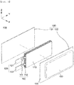
FIG. 1 is a perspective view schematically showing a battery module according to a first embodiment of the present invention. -
FIG. 2 is a perspective view schematically showing a battery cell of the battery module according to the first embodiment of the present invention. -
FIG. 3 is an exploded perspective view schematically showing the battery cell of the battery module according to the first embodiment of the present invention. -
FIG. 4 is a sectional view schematically showing the battery module according to the first embodiment of the present invention. -
FIG. 5 is a sectional view schematically showing another example of the battery module according to the first embodiment of the present invention. -
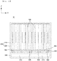
FIG. 6 is a perspective view schematically showing a support member of the battery module according to the first embodiment of the present invention. -
FIG. 7 is a view schematically showing a temperature distribution in a region where a plurality of battery cells are arranged in the first embodiment of the present invention. -
FIG. 8 is a perspective view schematically showing a heat dissipation pad and a support member of a battery module according to a second embodiment of the present invention. -
FIG. 9 is a sectional view schematically showing the battery module according to the second embodiment of the present invention. -
FIG. 10 is a sectional view schematically showing another example of the battery module according to the second embodiment of the present invention. - Hereinafter, a battery module according to an embodiment of the present invention will be described with reference to the accompanying drawings.
- As shown in
FIG. 1 , abattery module 10 according to a first embodiment of the present invention includes a plurality ofbattery cells 100 stacked on each other, ahousing 200 accommodating thebattery cells 100, and aheat sink 300 connected to thehousing 200. - The plurality of
battery cells 100 are disposed to face each other. The plurality ofbattery cells 100 may be electrically connected to each other. Hereinafter, the length direction of thebattery cell 100 will be defined as a Y-axis direction, the width direction of thebattery cell 100 will be defined as a Z-axis direction, and the thickness direction of thebattery cell 100 will be defined as an X-axis direction. Here, the plurality ofbattery cells 100 are stacked in the X-axis direction. - As shown in
FIGS. 2 and3 , each of thebattery cells 100 includes anelectrode assembly 110, electrode leads 120, and apouch 130. - The
electrode assembly 110 includes a plurality of electrode plates and a plurality of separators interposed between the plurality of electrode plates. The plurality of electrode plates include one or more positive electrode plates and one or more negative electrode plates. Each of the electrode plates of theelectrode assembly 110 is provided with anelectrode tab 140. Theelectrode tab 140 is configured so as to protrude outwards from a corresponding one of the electrode plates. - The end (the connection part) of each of the electrode leads 120 is connected to the
electrode assembly 110 via theelectrode tabs 140, and the end of theelectrode lead 120 that is opposite the connection part of the electrode lead, which is connected to theelectrode assembly 110, is exposed out of thepouch 130. The electrode leads 120 serve as electrode terminals of thebattery module 10. The electrode leads 121 and 122 are electrically connected to theelectrode assembly 110 through theelectrode tabs 140. The electrode leads 121 and 122 are welded to connection parts of theelectrode tabs 140, whereby the electrode leads are connected to theelectrode tabs 140. - Each of the plurality of electrode plates, i.e. the positive electrode plates and the negative electrode plates, is provided with the
electrode tabs 140. Theelectrode tabs 140 includepositive electrode tabs 141, which are connected to thepositive electrode lead 121, andnegative electrode tabs 142, which are connected to thenegative electrode lead 122. A plurality ofpositive electrode tabs 141 is connected to a singlepositive electrode lead 121, and a plurality ofnegative electrode tabs 142 is connected to a singlenegative electrode lead 122. - The
pouch 130 has therein a reception space, configured to receive theelectrode assembly 110, and an electrolytic solution. Thepouch 130 includes afirst pouch member 131 and asecond pouch member 132. Aconcave reception recess 133 is formed in one of thefirst pouch member 131 and thesecond pouch member 132. - The
first pouch member 131 and thesecond pouch member 132 are coupled to each other in order to form the reception space. The edges of thefirst pouch member 131 and thesecond pouch member 132 are sealed together by thermal bonding, etc., whereby the reception space is hermetically sealed. Thepouch 130 has anextension part 135, which extends from the part of the pouch in which the reception space is formed, and the electrode leads 120 are withdrawn outwards from theextension part 135. - As shown in
FIGS. 4 and5 , ahousing 200 accommodates the plurality ofbattery cells 100. Thehousing 200 includes acover member 210 and asupport member 220. Thecover member 210 and thesupport member 220 are coupled to each other in order to form a space to accommodate the plurality ofbattery cells 100 in thehousing 200. Thesupport member 220 serves to support the plurality ofbattery cells 100. In addition, thesupport member 220 serves to transfer heat generated from the plurality ofbattery cells 100 to theheat sink 300 by contacting theheat sink 300. Thecover member 210 serves to cover the plurality ofbattery cells 100 supported by thesupport member 220 so as to protect the plurality ofbattery cells 100 from the outside. - As shown in
FIG. 4 , the plurality ofbattery cells 100 may be in direct contact with thesupport member 220. In this case, heat generated in the plurality ofbattery cells 100 may be directly transferred to thesupport member 220, and then transferred to theheat sink 300. - In another example, as shown in
FIG. 5 , a thermal interface material (TIM) 400 may be interposed between the plurality ofbattery cells 100 and thesupport member 220. Thethermal interface material 400 may have adhesive properties. In this case, the plurality ofbattery cells 100 may be attached to thesupport member 220 through thethermal interface material 400 having adhesive properties. In addition, a state in which the plurality ofbattery cells 100 are stacked may be maintained by thethermal interface material 400. As thethermal interface material 400, at least one of a heat dissipating grease, a thermally conductive adhesive, and a phase change material may be used. In this case, the heat generated in the plurality ofbattery cells 100 may be transferred to thesupport member 220 through thethermal interface material 400, and then transferred to theheat sink 300. Since thethermal interface material 400 may be in close contact with the surfaces of the plurality ofbattery cells 100 as thethermal interface material 400 is made of a resin material, thethermal interface material 400 may smoothly absorb heat generated from the plurality ofbattery cells 100 and transfer the heat to thesupport member 220. - The
support member 220 may be made of a metal material to guarantee rigidity and smooth heat transfer. For example, it is preferable that thesupport member 220 is made of aluminum to guarantee rigidity and smooth heat transfer as well as lightness. - As shown in
FIG. 6 , a plurality of through-holes 225 may be formed in thesupport member 220. Each of the plurality of through-holes 225 may have various shapes such as a circular shape and a polygonal shape. The plurality of through-holes 225 may serve to reduce the contact resistance between the plurality ofbattery cells 100 and thesupport member 220. - The inside of the plurality of through-
holes 225 may be filled with thethermal interface material 400. Thethermal interface material 400 may contact the plurality ofbattery cells 100 and theheat sink 300 through the through-holes 225. Accordingly, the heat generated in the plurality ofbattery cells 100 may be transferred to theheat sink 300 through thethermal interface material 400. - As such, the plurality of through-
holes 225 are formed in thesupport member 220 and the plurality of through-holes 225 are filled with thethermal interface material 400. Therefore, the heat generated in the plurality ofbattery cells 100 may be smoothly discharged to the outside through thethermal interface material 400 in thesupport member 220 and the through-holes 225. - Therefore, as shown in
FIG. 4 , even in the case in which thethermal interface material 400 is not interposed between the plurality ofbattery cells 100 and thesupport member 220, the heat generated in the plurality ofbattery cells 100 may be smoothly discharged to the outside through thethermal interface material 400 in thesupport member 220 and through-holes 225. - Meanwhile, as shown in
FIG. 5 , thethermal interface material 400 may be provided between the plurality ofbattery cells 100 and thesupport member 220 so as to be connected to thethermal interface material 400 in the plurality of through-holes 225 of thesupport member 220. In this case, since the heat transfer efficiency increases as the plurality of through-holes 225 of thesupport member 220 are filled with thethermal interface material 400, the amount ofthermal interface material 400 interposed between the plurality ofbattery cells 100 and thesupport member 220 may be reduced. Therefore, as the amount of thethermal interface material 400 is reduced, the weight of thebattery module 10 may be reduced, and the cost required for using thethermal interface material 400 may be reduced. - Meanwhile, the plurality of through-
holes 225 formed in thesupport member 220 may be disposed at a predetermined distance from each other. However, in consideration of the temperature distribution in the region where the plurality ofbattery cells 100 are disposed, it is preferable that the plurality of through-holes 225 are distributed in an appropriate pattern. - As shown in
FIG. 7 , the temperature of the plurality ofbattery cells 100 in thebattery module 10 is not uniform as a whole, and there are a high temperature region in which the temperature is relatively high, a low temperature region in which the temperature is relatively low, and a middle region having a temperature gradient (a temperature gradually changing) between the high temperature region and the low temperature region. - Therefore, in the portion of the
support member 220 corresponding to the high temperature region in order that the heat can be smoothly discharged to the outside, it is preferable to arrange the plurality of through-holes 225 at a smaller distance (i.e., a larger number of the through-holes 225 are arranged densely) compared to the remaining portions. In the portion of thesupport member 220 corresponding to the low temperature region, it is preferable to arrange the plurality of through-holes 225 at a larger distance (i.e., a smaller number of the through-holes 225 are arranged) compared to the remaining portions. In addition, in the portion of thesupport member 220 corresponding to the middle region, it is preferable that the distance between the plurality of through-holes 225 gradually increases in the direction from the high temperature region toward the low temperature region (i.e., the number of the plurality of through-holes 225 gradually decreases in the direction from the high temperature region toward the low temperature region). - As such, the region where the plurality of
battery cells 100 are disposed is divided into a plurality of temperature regions based on the temperature distribution of the plurality ofbattery cells 100, and the distance between the plurality of through-holes 225 is set differently according to the plurality of temperature regions. Therefore, heat generated in the plurality ofbattery cells 100 may be discharged more efficiently. In particular, since the plurality of through-holes 225 may be formed at a larger distance (in a small number) in the portion of thesupport member 220 corresponding to the low temperature region, the number of the plurality of through-holes 225 may be reduced as compared with a case where the plurality of through-holes 225 are formed at a predetermined distance from each other with respect to the entire region where the plurality ofbattery cells 100 are disposed. Therefore, the number of man-hours and time required for processing the plurality of through-holes 225 into thesupport member 220 and filling the plurality of through-holes 225 with thethermal interface material 400 may be reduced. In addition, as the amount of thethermal interface material 400 necessary for filling the plurality of through-holes 225 may be reduced, the cost required for using thethermal interface material 400 may be reduced. - Meanwhile, the
heat sink 300 contacts the other surface of thesupport member 220 opposite to one surface of thesupport member 220 facing the plurality ofbattery cells 100. A coolingchannel 310 is formed in theheat sink 300. A coolant for cooling the plurality ofbattery cells 100 may flow into the coolingchannel 310. The coolant may be a cooling gas or cooling water. The heat generated in the plurality ofbattery cells 100 is transferred to thesupport member 220 and then transferred to theheat sink 300 to be absorbed by the coolant flowing in thecooling channel 310 of theheat sink 300. - According to the first embodiment of the present invention, the plurality of through-
holes 225 are formed in thesupport member 220 adjacent to the plurality ofbattery cells 100 and in contact with theheat sink 300, and the plurality of through-holes 225 are filled with thethermal interface material 400. Therefore, the heat generated in the plurality ofbattery cells 100 may be smoothly discharged to theheat sink 300 through thethermal interface material 400 in the plurality of through-holes 225. Therefore, since the amount of thethermal interface material 400 may be reduced in the case in which there is no need to interpose a separatethermal interface material 400 between the plurality ofbattery cells 100 and thesupport member 220, or thethermal interface material 400 is interposed between the plurality ofbattery cells 100 and thesupport member 220, the weight of thebattery module 10 may be reduced and the cost required for using thethermal interface material 400 may be reduced. - In addition, according to the first embodiment of the present invention, the region where the plurality of
battery cells 100 are disposed is divided into the plurality of temperature regions based on the temperature distribution of the plurality ofbattery cells 100 and the distance between the plurality of through-holes 225 is set differently according to the plurality of temperature regions. Therefore, the heat generated from the plurality ofbattery cells 100 may be discharged more efficiently. In particular, the through-holes 225 may be formed by reducing the number of through-holes 225 in the portion corresponding to the low temperature region, and the number of man-hours and time required to fill the through-holes 225 with thethermal interface material 400 may be reduced. - Hereinafter, a battery module according to a second embodiment of the present invention will be described with reference to
FIGS. 8 to 10 . The same components as those of the first embodiment described above are denoted by the same reference numerals, and a detailed description thereof will be omitted. - As shown in
FIGS. 8 to 10 , thebattery module 10 according to the second embodiment of the present invention may further comprise aheat dissipation pad 500 disposed between a plurality ofbattery cells 100 and asupport member 220. - It is preferable that the
heat dissipation pad 500 is made of a material having thermal conductivity and buffering properties. - As shown in
FIG. 9 , the plurality ofbattery cells 100 may directly contact theheat dissipation pad 500. In this case, the heat generated in the plurality ofbattery cells 100 may be directly transferred to theheat dissipation pad 500 and then transferred to theheat sink 300 through thesupport member 220. - In another example, as shown in
FIG. 10 , athermal interface material 400 may be interposed between the plurality ofbattery cells 100 and theheat dissipation pad 500. In this case, the heat generated from the plurality ofbattery cells 100 may be transferred to theheat dissipation pad 500 through thethermal interface material 400 and then transferred to theheat sink 300 through thesupport member 220. - As shown in
FIG. 8 , a plurality of through-holes 525 may be formed in theheat dissipation pad 500. The plurality of through-holes 525 of theheat dissipation pad 500 may be formed at positions corresponding to the plurality of through-holes 225 of thesupport member 220. Each of the plurality of through-holes 525 may have various shapes such as a circular shape and a polygonal shape. The inside of the plurality of through-holes 525 may be filled with thethermal interface material 400. Thethermal interface material 400 may contact the plurality ofbattery cells 100, thesupport member 220, and thethermal interface material 400 in the through-holes 225 of thesupport member 220 through the through-holes 525. Therefore, the heat generated in the plurality ofbattery cells 100 may be transferred to thesupport member 220 through thethermal interface material 400. - Therefore, as shown in
FIG. 9 , even in the case in which a separatethermal interface material 400 is not interposed between the plurality ofbattery cells 100 and theheat dissipation pad 500, the heat generated from the plurality ofbattery cells 100 may be smoothly discharged to the outside through theheat dissipation pad 500, thethermal interface material 400 in the through-holes 525 of theheat dissipation pad 500, thesupport member 220, and thethermal interface material 400 of the through-holes 225 of thesupport member 220. - In addition, as shown in
FIG. 10 , thethermal interface material 400 may be provided between the plurality ofbattery cells 100 and theheat dissipation pad 500 so as to be connected to thethermal interface material 400 in the plurality of through-holes 525 of theheat dissipation pad 500. In this case, since the heat transfer efficiency increases as the plurality of through-holes 525 of theheat dissipation pad 500 are filled with thethermal interface material 400, the amount of thethermal interface material 400 interposed between the plurality ofbattery cells 100 and theheat dissipation pad 500 may be reduced. Therefore, as the amount of thethermal interface material 400 is reduced, the weight of thebattery module 10 may be reduced, and the cost of using thethermal interface material 400 may be reduced. - Meanwhile, in consideration of the temperature distribution of the entire region where the plurality of
battery cells 100 are disposed, it is preferable that the plurality of through-holes 525 are appropriately distributed in theheat dissipation pad 500. The distance and distribution patterns of the plurality of through-holes 525 of theheat dissipation pad 500 may be similar to or the same as the distance and distribution patterns of the plurality of through-holes 225 formed in thesupport member 220. Accordingly, thethermal interface material 400 in the through-hole 525 of theheat dissipation pad 500 may be connected to thethermal interface material 400 in the through-holes 225 of thesupport member 220, thereby the heat generated from the plurality ofbattery cells 100 may be smoothly discharged to the outside through thethermal interface material 400 in the through-holes 525 of theheat dissipation pad 500 and thethermal interface material 400 in the through-holes 225 of thesupport member 220. - Accordingly, the region where the plurality of
battery cells 100 are disposed is divided into a plurality of temperature regions based on the temperature distribution of the plurality ofbattery cells 100, and the distance between the plurality of through-holes 525 is set differently according to the plurality of temperature regions. Therefore, heat generated in the plurality ofbattery cells 100 may be discharged more efficiently. In particular, since the plurality of through-holes 525 may be formed at a larger distance (in a small number) in the portion of theheat dissipation pad 500 corresponding to the low temperature region, the number of man-hours and time required for processing the plurality of through-holes 525 into theheat dissipation pad 500 and filling the plurality of through-holes 525 with thethermal interface material 400 may be reduced as compared with a case where the plurality of through-holes 525 are formed at a predetermined distance from each other with respect to the entire region where the plurality ofbattery cells 100 are disposed. In addition, as the amount of thethermal interface material 400 necessary for filling the plurality of through-holes 525 may be reduced, the cost required for using thethermal interface material 400 may be reduced. - According to the second embodiment of the present invention, the plurality of through-
holes 525 are formed in theheat dissipation pad 500 which is provided between the plurality ofbattery cells 100 and thesupport member 220, and the plurality of through-holes 525 are filled with thethermal interface material 400. As a result, the heat generated in the plurality ofbattery cells 100 may be smoothly discharged to the outside through thethermal interface material 400 in the plurality of through-holes 525 of theheat dissipation pad 500 and thethermal interface material 400 in the plurality of through-holes 225 of thesupport member 220. Therefore, since the amount of thethermal interface material 400 may be reduced in the case in which there is no need to interpose a separatethermal interface material 400 between the plurality ofbattery cells 100 and theheat dissipation pad 500, or thethermal interface material 400 is interposed between the plurality ofbattery cells 100 and theheat dissipation pad 500, the weight of thebattery module 10 may be reduced and the cost required for using thethermal interface material 400 may be reduced. - In addition, according to the second embodiment of the present invention, the region where the plurality of
battery cells 100 are disposed is divided into the plurality of temperature regions based on the temperature distribution of the plurality ofbattery cells 100 and the distance between the plurality of through-holes 525 is set differently according to the plurality of temperature regions. Therefore, the heat generated from the plurality ofbattery cells 100 may be discharged more efficiently, and the number of man-hours and time required to fill the through-holes 525 with thethermal interface material 400 may be reduced by reducing the number of through-holes 525 in the portion corresponding to the low temperature region. - Although the preferred embodiments of the present invention have been described by way of illustration, the scope of the present invention is not limited to the specific embodiments described herein, and the present invention can be appropriately modified within the category described in the claims.
-
- 100:
- Battery cell
- 200:
- Housing
- 300:
- Heat sink
- 400:
- Thermal interface material
- 500:
- Heat dissipation pad
- According to an embodiment of the present invention, a plurality of through-holes are formed in a support member adjacent to a plurality of battery cells and in contact with a heat sink, and the plurality of through-holes are filled with a thermal interface material. As a result, heat generated in the plurality of battery cells may be smoothly discharged to the heat sink through the thermal interface material in the plurality of through-holes. Therefore, since the amount of the thermal interface material may be reduced even in the case in which there is no need to interpose a separate thermal interface material between the plurality of battery cells and the support member, or the thermal interface material is interposed between the plurality of battery cells and the support member, the weight of a battery module may be reduced and the cost required for using the thermal interface material may be reduced.
- In addition, according to the embodiment of the present invention, a region where the plurality of battery cells are disposed is divided into a plurality of temperature regions based on the temperature distribution of the plurality of battery cells and the distance between the plurality of through-holes is set differently according to the plurality of temperature regions. Therefore, heat generated from the plurality of battery cells may be discharged more efficiently. In particular, the number of man-hours and time required to form the through-holes may be reduced by reducing the number of through-holes in the portion corresponding to the low temperature region.
Claims (10)
- A battery module comprising:a plurality of battery cells stacked on each other;a housing accommodating the plurality of battery cells and including a support member configured to support the plurality of battery cells; anda heat sink configured to contact the support member,wherein the support member has a plurality of through-holes formed therein, and the plurality of through-holes are filled with a thermal interface material.
- The battery module according to claim 1,
wherein a region in which the plurality of battery cells are disposed is divided into a plurality of temperature regions based on a temperature distribution of the plurality of battery cells, and
wherein a distance between the plurality of through-holes formed in the support member is set differently according to the plurality of temperature regions. - The battery module according to claim 2, wherein:the plurality of temperature regions comprise a high temperature region, a low temperature region, and a middle region between the high temperature region and the low temperature region, anda distance between the plurality of through-holes in a portion of the support member corresponding to the middle region gradually increases along a direction from the high temperature region towards the low temperature region.
- The battery module according to claim 1, wherein a thermal interface material is interposed between the plurality of battery cells and the support member so as to be connected to the thermal interface material in the plurality of through-holes of the support member.
- The battery module according to claim 1, further comprising a heat dissipation pad disposed between the plurality of battery cells and the support member,
wherein the heat dissipation pad has a plurality of through-holes formed therein, and the plurality of through-holes of the heat dissipation pad are filled with the thermal interface material. - The battery module according to claim 5, wherein:the plurality of through-holes of the heat dissipation pad are formed at positions corresponding to the plurality of through-holes of the support member, andthe thermal interface material in the plurality of through-holes of the heat dissipation pad and the thermal interface material in the plurality of through-holes of the support member are connected to each other.
- The battery module according to claim 5,
wherein a region in which the plurality of battery cells are disposed is divided into a plurality of temperature regions based on a temperature distribution of the plurality of battery cells, and
wherein a distance between the plurality of through-holes formed in the heat dissipation pad is set differently according to the plurality of temperature regions. - The battery module according to claim 7, wherein:the plurality of temperature regions comprise a high temperature region, a low temperature region, and a middle region between the high temperature region and the low temperature region, anda distance between the plurality of through-holes in a portion of the heat dissipation pad corresponding to the middle region gradually increases along a direction from the high temperature region towards the low temperature region.
- The battery module according to claim 5, wherein a thermal interface material is interposed between the plurality of battery cells and the heat dissipation pad so as to be connected to the thermal interface material in the plurality of through-holes of the heat dissipation pad.
- A battery pack comprising the battery module according to any one of claims 1 to 9.
Applications Claiming Priority (2)
| Application Number | Priority Date | Filing Date | Title |
|---|---|---|---|
| KR1020180077325A KR102523702B1 (en) | 2018-07-03 | 2018-07-03 | Battery module |
| PCT/KR2019/008118 WO2020009465A1 (en) | 2018-07-03 | 2019-07-03 | Battery module |
Publications (3)
| Publication Number | Publication Date |
|---|---|
| EP3686987A1 true EP3686987A1 (en) | 2020-07-29 |
| EP3686987A4 EP3686987A4 (en) | 2021-03-17 |
| EP3686987B1 EP3686987B1 (en) | 2023-08-30 |
Family
ID=69060105
Family Applications (1)
| Application Number | Title | Priority Date | Filing Date |
|---|---|---|---|
| EP19831022.9A Active EP3686987B1 (en) | 2018-07-03 | 2019-07-03 | Battery module |
Country Status (6)
| Country | Link |
|---|---|
| US (2) | US11258116B2 (en) |
| EP (1) | EP3686987B1 (en) |
| JP (1) | JP7102020B2 (en) |
| KR (1) | KR102523702B1 (en) |
| CN (1) | CN111712968B (en) |
| WO (1) | WO2020009465A1 (en) |
Cited By (3)
| Publication number | Priority date | Publication date | Assignee | Title |
|---|---|---|---|---|
| EP4040574A4 (en) * | 2020-01-16 | 2022-11-30 | LG Energy Solution, Ltd. | BATTERY MODULE AND BATTERY PACK COMPRISING THEM |
| EP4531178A4 (en) * | 2023-02-28 | 2025-07-02 | Lg Energy Solution Ltd | PACKAGE HOUSING WITH IMPROVED HEAT DISSIPATION STRUCTURE |
| EP4567983A4 (en) * | 2023-02-28 | 2025-07-09 | Lg Energy Solution Ltd | BATTERY MODULE WITH IMPROVED HEAT DISSIPATION STRUCTURE |
Families Citing this family (21)
| Publication number | Priority date | Publication date | Assignee | Title |
|---|---|---|---|---|
| KR102418265B1 (en) * | 2019-08-08 | 2022-07-07 | 주식회사 엘지에너지솔루션 | Battery Pack Comprising Heating Member |
| KR102873691B1 (en) | 2020-01-22 | 2025-10-17 | 주식회사 엘지에너지솔루션 | Battery module |
| US11522237B2 (en) * | 2020-02-06 | 2022-12-06 | Lenovo (Singapore) Pte. Ltd. | Heat control in battery pack stack |
| KR20210150843A (en) * | 2020-06-04 | 2021-12-13 | 주식회사 엘지에너지솔루션 | Battery module and battery pack including the same |
| KR102937900B1 (en) * | 2020-06-10 | 2026-03-11 | 주식회사 엘지에너지솔루션 | Battery module and menufacturing method for the same |
| KR102937901B1 (en) | 2020-06-10 | 2026-03-11 | 주식회사 엘지에너지솔루션 | Battery module and menufacturing method for the same |
| KR20220049870A (en) * | 2020-10-15 | 2022-04-22 | 주식회사 엘지에너지솔루션 | Battery module and battery pack including the same |
| KR20220112514A (en) | 2021-02-04 | 2022-08-11 | 주식회사 엘지에너지솔루션 | Battery Module with Improved Temperature Uniformity of Battery Cells |
| WO2022182036A1 (en) * | 2021-02-23 | 2022-09-01 | 주식회사 엘지에너지솔루션 | Battery module and battery pack including same |
| DE102021104914A1 (en) | 2021-03-02 | 2022-09-08 | Dr. Ing. H.C. F. Porsche Aktiengesellschaft | Battery module, vehicle with this battery module and method for manufacturing the battery module |
| CN216120451U (en) * | 2021-07-20 | 2022-03-22 | 宁德时代新能源科技股份有限公司 | End cover assembly, battery monomer, battery and device using battery |
| DE102021127842B4 (en) * | 2021-10-26 | 2024-07-18 | Dr. Ing. H.C. F. Porsche Aktiengesellschaft | Method for filling a thermal paste into a battery module and battery module |
| CN114094244B (en) * | 2021-11-22 | 2024-08-27 | 东莞新能安科技有限公司 | Battery packs and electrical equipment |
| KR102677146B1 (en) * | 2021-12-24 | 2024-06-20 | 주식회사 엘지에너지솔루션 | Battery module and battery pack and vehicle including the same |
| DE102022102830A1 (en) | 2022-02-07 | 2023-08-10 | Audi Aktiengesellschaft | Battery cell assembly, battery and method for providing a battery cell assembly |
| KR20230135998A (en) * | 2022-03-17 | 2023-09-26 | 주식회사 엘지에너지솔루션 | Heat sink, manufacturing method thereof, and battery module |
| KR20240164940A (en) * | 2022-03-31 | 2024-11-21 | 혼다 기켄 고교 가부시키가이샤 | Batteries, battery modules and laminate films |
| US20230361416A1 (en) * | 2022-05-06 | 2023-11-09 | Calb Co., Ltd. | Battery pack and vehicle |
| KR102872030B1 (en) * | 2022-09-01 | 2025-10-15 | 주식회사 엘지에너지솔루션 | Battery pack with improved safety |
| KR102872644B1 (en) * | 2023-07-21 | 2025-10-16 | 주식회사 엘지에너지솔루션 | Battery pack |
| KR20250122938A (en) * | 2024-02-07 | 2025-08-14 | 주식회사 엘지에너지솔루션 | Battery module, Battery pack and vehicle including the same |
Family Cites Families (24)
| Publication number | Priority date | Publication date | Assignee | Title |
|---|---|---|---|---|
| JP5259602B2 (en) | 2006-09-25 | 2013-08-07 | エルジー・ケム・リミテッド | Cell module cartridge and medium-to-large battery module including the same |
| KR101156958B1 (en) * | 2010-05-27 | 2012-06-21 | 주식회사 코캄 | Battery pack and battery pack assembly for electric vehicle and temperature control system using thereof |
| US9196938B2 (en) * | 2010-07-06 | 2015-11-24 | Samsung Sdi Co., Ltd. | Battery module |
| KR101201742B1 (en) * | 2010-11-05 | 2012-11-15 | 에스비리모티브 주식회사 | Battery module |
| US9509023B2 (en) | 2011-12-09 | 2016-11-29 | Honda Motor Co., Ltd. | Structure for securing battery |
| AU2012200345B2 (en) | 2012-01-20 | 2014-05-01 | Canon Kabushiki Kaisha | Method, apparatus and system for encoding and decoding the significance map residual coefficients of a transform unit |
| US20140234668A1 (en) | 2013-02-19 | 2014-08-21 | Faster Faster, Inc. | Battery Housing with Single-Side Electrical Interconnects |
| JP6073737B2 (en) * | 2013-04-24 | 2017-02-01 | 日立オートモティブシステムズ株式会社 | Power storage module |
| US10153526B2 (en) | 2013-07-17 | 2018-12-11 | Calsonic Kansei Corporation | Assembled battery |
| KR101690573B1 (en) | 2014-08-29 | 2016-12-28 | 에스케이이노베이션 주식회사 | Label for being attached to a flexible case of a lithum secondary battery, lithium secondary battery with such label attatched thereto, and battery module including such lithium secondary battery |
| KR101900998B1 (en) * | 2015-06-18 | 2018-09-20 | 주식회사 엘지화학 | Lightweight cooling plate, battery module comprising the same and fabricating method thereof |
| KR102392459B1 (en) * | 2015-09-01 | 2022-04-29 | 에이치그린파워 주식회사 | Cover having cooling hole for battery cell of eco-friendly vehicle |
| CN205016642U (en) * | 2015-10-09 | 2016-02-03 | 北京长城华冠汽车科技股份有限公司 | Battery cell's heat abstractor , battery module and car |
| CN108701880B (en) | 2016-03-14 | 2022-04-08 | 松下知识产权经营株式会社 | Composite sheet and battery pack using the same |
| KR102112716B1 (en) * | 2016-03-16 | 2020-05-19 | 주식회사 엘지화학 | Battery module, battery pack the battery module and vehicle comprising the battery pack |
| KR102067710B1 (en) | 2016-07-06 | 2020-01-17 | 주식회사 엘지화학 | Battery module, battery pack comprising the battery module and vehicle comprising the battery pack |
| KR102413433B1 (en) * | 2016-07-13 | 2022-06-28 | 에스케이온 주식회사 | Battery module |
| CN206076435U (en) * | 2016-07-21 | 2017-04-05 | 北京新能源汽车股份有限公司 | Power battery and automobile with same |
| CN107713660A (en) | 2016-08-13 | 2018-02-23 | 颜茹玉 | Triangle folding clothes hanger |
| US10305152B2 (en) * | 2016-09-26 | 2019-05-28 | Hyundai Motor Company | Water cooling system for a battery |
| KR102086127B1 (en) * | 2016-10-31 | 2020-03-06 | 주식회사 엘지화학 | Battery pack for providing direct cooling means to edge side of battery |
| CN206250349U (en) * | 2016-11-04 | 2017-06-13 | 宁德时代新能源科技股份有限公司 | Battery modules |
| CN206520349U (en) | 2016-12-15 | 2017-09-26 | 上海净意信息科技有限公司 | A kind of two-dimensional code scanning and review printing equipment |
| CN206322821U (en) * | 2016-12-22 | 2017-07-11 | 上海思致汽车工程技术有限公司 | A kind of electrokinetic cell module with high heat dispersion |
-
2018
- 2018-07-03 KR KR1020180077325A patent/KR102523702B1/en active Active
-
2019
- 2019-07-03 JP JP2020522387A patent/JP7102020B2/en active Active
- 2019-07-03 US US16/760,990 patent/US11258116B2/en active Active
- 2019-07-03 CN CN201980013077.3A patent/CN111712968B/en active Active
- 2019-07-03 WO PCT/KR2019/008118 patent/WO2020009465A1/en not_active Ceased
- 2019-07-03 EP EP19831022.9A patent/EP3686987B1/en active Active
-
2022
- 2022-01-11 US US17/573,158 patent/US11637335B2/en active Active
Cited By (4)
| Publication number | Priority date | Publication date | Assignee | Title |
|---|---|---|---|---|
| EP4040574A4 (en) * | 2020-01-16 | 2022-11-30 | LG Energy Solution, Ltd. | BATTERY MODULE AND BATTERY PACK COMPRISING THEM |
| US12327850B2 (en) | 2020-01-16 | 2025-06-10 | Lg Energy Solution, Ltd. | Battery module and battery pack including the same |
| EP4531178A4 (en) * | 2023-02-28 | 2025-07-02 | Lg Energy Solution Ltd | PACKAGE HOUSING WITH IMPROVED HEAT DISSIPATION STRUCTURE |
| EP4567983A4 (en) * | 2023-02-28 | 2025-07-09 | Lg Energy Solution Ltd | BATTERY MODULE WITH IMPROVED HEAT DISSIPATION STRUCTURE |
Also Published As
| Publication number | Publication date |
|---|---|
| CN111712968A (en) | 2020-09-25 |
| US11258116B2 (en) | 2022-02-22 |
| WO2020009465A1 (en) | 2020-01-09 |
| US20200313253A1 (en) | 2020-10-01 |
| EP3686987B1 (en) | 2023-08-30 |
| KR20200004202A (en) | 2020-01-13 |
| US20220131207A1 (en) | 2022-04-28 |
| CN111712968B (en) | 2023-10-24 |
| US11637335B2 (en) | 2023-04-25 |
| EP3686987A4 (en) | 2021-03-17 |
| JP7102020B2 (en) | 2022-07-19 |
| KR102523702B1 (en) | 2023-04-19 |
| JP2021500708A (en) | 2021-01-07 |
Similar Documents
| Publication | Publication Date | Title |
|---|---|---|
| US11637335B2 (en) | Battery module | |
| EP3731304B1 (en) | Battery module | |
| CN109891624B (en) | Battery pack with anti-collision beam structure | |
| CN110100351B (en) | Battery pack including heat transfer medium having louver blade shape | |
| CN102299363B (en) | Battery assembly with cooling, electric vehicle and battery shell | |
| KR102112716B1 (en) | Battery module, battery pack the battery module and vehicle comprising the battery pack | |
| KR20210065268A (en) | Busbar Frame Assembly and Battery module including the same | |
| US20150050523A1 (en) | Battery pack | |
| KR20200065192A (en) | Battery Pack Having Heat Dissipating Member | |
| KR101134134B1 (en) | Secondary battery module | |
| KR20170021561A (en) | Battery pack | |
| KR102499869B1 (en) | Battery module | |
| CN119318060A (en) | Batteries and electrical devices | |
| EP3780143B1 (en) | Battery module | |
| EP4181274A1 (en) | Battery module and battery pack including same | |
| US12362413B2 (en) | Battery cell, and battery module, battery pack and vehicle including the same | |
| CN223167550U (en) | Battery cells, batteries and electrical equipment | |
| US20260135183A1 (en) | Battery Cell Assembly and Battery Pack Including the Same | |
| WO2024009313A1 (en) | Heat transfer in battery module assemblies |
Legal Events
| Date | Code | Title | Description |
|---|---|---|---|
| STAA | Information on the status of an ep patent application or granted ep patent |
Free format text: STATUS: THE INTERNATIONAL PUBLICATION HAS BEEN MADE |
|
| PUAI | Public reference made under article 153(3) epc to a published international application that has entered the european phase |
Free format text: ORIGINAL CODE: 0009012 |
|
| STAA | Information on the status of an ep patent application or granted ep patent |
Free format text: STATUS: REQUEST FOR EXAMINATION WAS MADE |
|
| 17P | Request for examination filed |
Effective date: 20200424 |
|
| AK | Designated contracting states |
Kind code of ref document: A1 Designated state(s): AL AT BE BG CH CY CZ DE DK EE ES FI FR GB GR HR HU IE IS IT LI LT LU LV MC MK MT NL NO PL PT RO RS SE SI SK SM TR |
|
| AX | Request for extension of the european patent |
Extension state: BA ME |
|
| A4 | Supplementary search report drawn up and despatched |
Effective date: 20210211 |
|
| RIC1 | Information provided on ipc code assigned before grant |
Ipc: H01M 50/20 20210101ALI20210205BHEP Ipc: H01M 10/653 20140101ALI20210205BHEP Ipc: H01M 10/655 20140101AFI20210205BHEP Ipc: H01M 10/647 20140101ALI20210205BHEP Ipc: H01M 10/617 20140101ALI20210205BHEP Ipc: H01M 10/6551 20140101ALI20210205BHEP |
|
| DAV | Request for validation of the european patent (deleted) | ||
| DAX | Request for extension of the european patent (deleted) | ||
| RAP1 | Party data changed (applicant data changed or rights of an application transferred) |
Owner name: LG ENERGY SOLUTION LTD. |
|
| RAP3 | Party data changed (applicant data changed or rights of an application transferred) |
Owner name: LG ENERGY SOLUTION, LTD. |
|
| REG | Reference to a national code |
Ref country code: DE Ref legal event code: R079 Free format text: PREVIOUS MAIN CLASS: H01M0010655000 Ipc: H01M0050211000 Ref document number: 602019036360 Country of ref document: DE |
|
| GRAP | Despatch of communication of intention to grant a patent |
Free format text: ORIGINAL CODE: EPIDOSNIGR1 |
|
| STAA | Information on the status of an ep patent application or granted ep patent |
Free format text: STATUS: GRANT OF PATENT IS INTENDED |
|
| RIC1 | Information provided on ipc code assigned before grant |
Ipc: H01M 10/647 20140101ALI20230505BHEP Ipc: H01M 10/6554 20140101ALI20230505BHEP Ipc: H01M 10/617 20140101ALI20230505BHEP Ipc: H01M 50/293 20210101ALI20230505BHEP Ipc: H01M 50/211 20210101AFI20230505BHEP |
|
| INTG | Intention to grant announced |
Effective date: 20230605 |
|
| GRAS | Grant fee paid |
Free format text: ORIGINAL CODE: EPIDOSNIGR3 |
|
| GRAA | (expected) grant |
Free format text: ORIGINAL CODE: 0009210 |
|
| STAA | Information on the status of an ep patent application or granted ep patent |
Free format text: STATUS: THE PATENT HAS BEEN GRANTED |
|
| P01 | Opt-out of the competence of the unified patent court (upc) registered |
Effective date: 20230706 |
|
| AK | Designated contracting states |
Kind code of ref document: B1 Designated state(s): AL AT BE BG CH CY CZ DE DK EE ES FI FR GB GR HR HU IE IS IT LI LT LU LV MC MK MT NL NO PL PT RO RS SE SI SK SM TR |
|
| REG | Reference to a national code |
Ref country code: GB Ref legal event code: FG4D |
|
| REG | Reference to a national code |
Ref country code: CH Ref legal event code: EP |
|
| REG | Reference to a national code |
Ref country code: DE Ref legal event code: R096 Ref document number: 602019036360 Country of ref document: DE |
|
| REG | Reference to a national code |
Ref country code: IE Ref legal event code: FG4D |
|
| REG | Reference to a national code |
Ref country code: LT Ref legal event code: MG9D |
|
| REG | Reference to a national code |
Ref country code: NL Ref legal event code: MP Effective date: 20230830 |
|
| REG | Reference to a national code |
Ref country code: AT Ref legal event code: MK05 Ref document number: 1606617 Country of ref document: AT Kind code of ref document: T Effective date: 20230830 |
|
| PG25 | Lapsed in a contracting state [announced via postgrant information from national office to epo] |
Ref country code: GR Free format text: LAPSE BECAUSE OF FAILURE TO SUBMIT A TRANSLATION OF THE DESCRIPTION OR TO PAY THE FEE WITHIN THE PRESCRIBED TIME-LIMIT Effective date: 20231201 |
|
| PG25 | Lapsed in a contracting state [announced via postgrant information from national office to epo] |
Ref country code: IS Free format text: LAPSE BECAUSE OF FAILURE TO SUBMIT A TRANSLATION OF THE DESCRIPTION OR TO PAY THE FEE WITHIN THE PRESCRIBED TIME-LIMIT Effective date: 20231230 |
|
| PG25 | Lapsed in a contracting state [announced via postgrant information from national office to epo] |
Ref country code: SE Free format text: LAPSE BECAUSE OF FAILURE TO SUBMIT A TRANSLATION OF THE DESCRIPTION OR TO PAY THE FEE WITHIN THE PRESCRIBED TIME-LIMIT Effective date: 20230830 Ref country code: RS Free format text: LAPSE BECAUSE OF FAILURE TO SUBMIT A TRANSLATION OF THE DESCRIPTION OR TO PAY THE FEE WITHIN THE PRESCRIBED TIME-LIMIT Effective date: 20230830 Ref country code: NO Free format text: LAPSE BECAUSE OF FAILURE TO SUBMIT A TRANSLATION OF THE DESCRIPTION OR TO PAY THE FEE WITHIN THE PRESCRIBED TIME-LIMIT Effective date: 20231130 Ref country code: LV Free format text: LAPSE BECAUSE OF FAILURE TO SUBMIT A TRANSLATION OF THE DESCRIPTION OR TO PAY THE FEE WITHIN THE PRESCRIBED TIME-LIMIT Effective date: 20230830 Ref country code: LT Free format text: LAPSE BECAUSE OF FAILURE TO SUBMIT A TRANSLATION OF THE DESCRIPTION OR TO PAY THE FEE WITHIN THE PRESCRIBED TIME-LIMIT Effective date: 20230830 Ref country code: IS Free format text: LAPSE BECAUSE OF FAILURE TO SUBMIT A TRANSLATION OF THE DESCRIPTION OR TO PAY THE FEE WITHIN THE PRESCRIBED TIME-LIMIT Effective date: 20231230 Ref country code: HR Free format text: LAPSE BECAUSE OF FAILURE TO SUBMIT A TRANSLATION OF THE DESCRIPTION OR TO PAY THE FEE WITHIN THE PRESCRIBED TIME-LIMIT Effective date: 20230830 Ref country code: GR Free format text: LAPSE BECAUSE OF FAILURE TO SUBMIT A TRANSLATION OF THE DESCRIPTION OR TO PAY THE FEE WITHIN THE PRESCRIBED TIME-LIMIT Effective date: 20231201 Ref country code: FI Free format text: LAPSE BECAUSE OF FAILURE TO SUBMIT A TRANSLATION OF THE DESCRIPTION OR TO PAY THE FEE WITHIN THE PRESCRIBED TIME-LIMIT Effective date: 20230830 Ref country code: AT Free format text: LAPSE BECAUSE OF FAILURE TO SUBMIT A TRANSLATION OF THE DESCRIPTION OR TO PAY THE FEE WITHIN THE PRESCRIBED TIME-LIMIT Effective date: 20230830 |
|
| PG25 | Lapsed in a contracting state [announced via postgrant information from national office to epo] |
Ref country code: PL Free format text: LAPSE BECAUSE OF FAILURE TO SUBMIT A TRANSLATION OF THE DESCRIPTION OR TO PAY THE FEE WITHIN THE PRESCRIBED TIME-LIMIT Effective date: 20230830 Ref country code: NL Free format text: LAPSE BECAUSE OF FAILURE TO SUBMIT A TRANSLATION OF THE DESCRIPTION OR TO PAY THE FEE WITHIN THE PRESCRIBED TIME-LIMIT Effective date: 20230830 |
|
| PG25 | Lapsed in a contracting state [announced via postgrant information from national office to epo] |
Ref country code: ES Free format text: LAPSE BECAUSE OF FAILURE TO SUBMIT A TRANSLATION OF THE DESCRIPTION OR TO PAY THE FEE WITHIN THE PRESCRIBED TIME-LIMIT Effective date: 20230830 |
|
| PG25 | Lapsed in a contracting state [announced via postgrant information from national office to epo] |
Ref country code: SM Free format text: LAPSE BECAUSE OF FAILURE TO SUBMIT A TRANSLATION OF THE DESCRIPTION OR TO PAY THE FEE WITHIN THE PRESCRIBED TIME-LIMIT Effective date: 20230830 Ref country code: RO Free format text: LAPSE BECAUSE OF FAILURE TO SUBMIT A TRANSLATION OF THE DESCRIPTION OR TO PAY THE FEE WITHIN THE PRESCRIBED TIME-LIMIT Effective date: 20230830 Ref country code: ES Free format text: LAPSE BECAUSE OF FAILURE TO SUBMIT A TRANSLATION OF THE DESCRIPTION OR TO PAY THE FEE WITHIN THE PRESCRIBED TIME-LIMIT Effective date: 20230830 Ref country code: EE Free format text: LAPSE BECAUSE OF FAILURE TO SUBMIT A TRANSLATION OF THE DESCRIPTION OR TO PAY THE FEE WITHIN THE PRESCRIBED TIME-LIMIT Effective date: 20230830 Ref country code: DK Free format text: LAPSE BECAUSE OF FAILURE TO SUBMIT A TRANSLATION OF THE DESCRIPTION OR TO PAY THE FEE WITHIN THE PRESCRIBED TIME-LIMIT Effective date: 20230830 Ref country code: CZ Free format text: LAPSE BECAUSE OF FAILURE TO SUBMIT A TRANSLATION OF THE DESCRIPTION OR TO PAY THE FEE WITHIN THE PRESCRIBED TIME-LIMIT Effective date: 20230830 Ref country code: SK Free format text: LAPSE BECAUSE OF FAILURE TO SUBMIT A TRANSLATION OF THE DESCRIPTION OR TO PAY THE FEE WITHIN THE PRESCRIBED TIME-LIMIT Effective date: 20230830 Ref country code: PT Free format text: LAPSE BECAUSE OF FAILURE TO SUBMIT A TRANSLATION OF THE DESCRIPTION OR TO PAY THE FEE WITHIN THE PRESCRIBED TIME-LIMIT Effective date: 20240102 |
|
| PG25 | Lapsed in a contracting state [announced via postgrant information from national office to epo] |
Ref country code: IT Free format text: LAPSE BECAUSE OF FAILURE TO SUBMIT A TRANSLATION OF THE DESCRIPTION OR TO PAY THE FEE WITHIN THE PRESCRIBED TIME-LIMIT Effective date: 20230830 |
|
| REG | Reference to a national code |
Ref country code: DE Ref legal event code: R097 Ref document number: 602019036360 Country of ref document: DE |
|
| PLBE | No opposition filed within time limit |
Free format text: ORIGINAL CODE: 0009261 |
|
| STAA | Information on the status of an ep patent application or granted ep patent |
Free format text: STATUS: NO OPPOSITION FILED WITHIN TIME LIMIT |
|
| PG25 | Lapsed in a contracting state [announced via postgrant information from national office to epo] |
Ref country code: SI Free format text: LAPSE BECAUSE OF FAILURE TO SUBMIT A TRANSLATION OF THE DESCRIPTION OR TO PAY THE FEE WITHIN THE PRESCRIBED TIME-LIMIT Effective date: 20230830 |
|
| 26N | No opposition filed |
Effective date: 20240603 |
|
| PG25 | Lapsed in a contracting state [announced via postgrant information from national office to epo] |
Ref country code: BG Free format text: LAPSE BECAUSE OF FAILURE TO SUBMIT A TRANSLATION OF THE DESCRIPTION OR TO PAY THE FEE WITHIN THE PRESCRIBED TIME-LIMIT Effective date: 20230830 |
|
| PG25 | Lapsed in a contracting state [announced via postgrant information from national office to epo] |
Ref country code: BG Free format text: LAPSE BECAUSE OF FAILURE TO SUBMIT A TRANSLATION OF THE DESCRIPTION OR TO PAY THE FEE WITHIN THE PRESCRIBED TIME-LIMIT Effective date: 20230830 |
|
| PG25 | Lapsed in a contracting state [announced via postgrant information from national office to epo] |
Ref country code: MC Free format text: LAPSE BECAUSE OF FAILURE TO SUBMIT A TRANSLATION OF THE DESCRIPTION OR TO PAY THE FEE WITHIN THE PRESCRIBED TIME-LIMIT Effective date: 20230830 |
|
| REG | Reference to a national code |
Ref country code: CH Ref legal event code: PL |
|
| PG25 | Lapsed in a contracting state [announced via postgrant information from national office to epo] |
Ref country code: LU Free format text: LAPSE BECAUSE OF NON-PAYMENT OF DUE FEES Effective date: 20240703 |
|
| PG25 | Lapsed in a contracting state [announced via postgrant information from national office to epo] |
Ref country code: LU Free format text: LAPSE BECAUSE OF NON-PAYMENT OF DUE FEES Effective date: 20240703 |
|
| PG25 | Lapsed in a contracting state [announced via postgrant information from national office to epo] |
Ref country code: CH Free format text: LAPSE BECAUSE OF NON-PAYMENT OF DUE FEES Effective date: 20240731 Ref country code: BE Free format text: LAPSE BECAUSE OF NON-PAYMENT OF DUE FEES Effective date: 20240731 |
|
| REG | Reference to a national code |
Ref country code: BE Ref legal event code: MM Effective date: 20240731 |
|
| PGFP | Annual fee paid to national office [announced via postgrant information from national office to epo] |
Ref country code: GB Payment date: 20250624 Year of fee payment: 7 |
|
| PGFP | Annual fee paid to national office [announced via postgrant information from national office to epo] |
Ref country code: FR Payment date: 20250624 Year of fee payment: 7 |
|
| PG25 | Lapsed in a contracting state [announced via postgrant information from national office to epo] |
Ref country code: IE Free format text: LAPSE BECAUSE OF NON-PAYMENT OF DUE FEES Effective date: 20240703 |
|
| PGFP | Annual fee paid to national office [announced via postgrant information from national office to epo] |
Ref country code: DE Payment date: 20250624 Year of fee payment: 7 |
|
| PG25 | Lapsed in a contracting state [announced via postgrant information from national office to epo] |
Ref country code: CY Free format text: LAPSE BECAUSE OF FAILURE TO SUBMIT A TRANSLATION OF THE DESCRIPTION OR TO PAY THE FEE WITHIN THE PRESCRIBED TIME-LIMIT; INVALID AB INITIO Effective date: 20190703 |
|
| PG25 | Lapsed in a contracting state [announced via postgrant information from national office to epo] |
Ref country code: HU Free format text: LAPSE BECAUSE OF FAILURE TO SUBMIT A TRANSLATION OF THE DESCRIPTION OR TO PAY THE FEE WITHIN THE PRESCRIBED TIME-LIMIT; INVALID AB INITIO Effective date: 20190703 |