EP3686954A1 - Battery module - Google Patents
Battery module Download PDFInfo
- Publication number
- EP3686954A1 EP3686954A1 EP19780914.8A EP19780914A EP3686954A1 EP 3686954 A1 EP3686954 A1 EP 3686954A1 EP 19780914 A EP19780914 A EP 19780914A EP 3686954 A1 EP3686954 A1 EP 3686954A1
- Authority
- EP
- European Patent Office
- Prior art keywords
- battery
- battery cells
- cell
- present disclosure
- stacking direction
- Prior art date
- Legal status (The legal status is an assumption and is not a legal conclusion. Google has not performed a legal analysis and makes no representation as to the accuracy of the status listed.)
- Pending
Links
Images





Classifications
-
- H—ELECTRICITY
- H01—ELECTRIC ELEMENTS
- H01M—PROCESSES OR MEANS, e.g. BATTERIES, FOR THE DIRECT CONVERSION OF CHEMICAL ENERGY INTO ELECTRICAL ENERGY
- H01M50/00—Constructional details or processes of manufacture of the non-active parts of electrochemical cells other than fuel cells, e.g. hybrid cells
- H01M50/20—Mountings; Secondary casings or frames; Racks, modules or packs; Suspension devices; Shock absorbers; Transport or carrying devices; Holders
-
- H—ELECTRICITY
- H01—ELECTRIC ELEMENTS
- H01M—PROCESSES OR MEANS, e.g. BATTERIES, FOR THE DIRECT CONVERSION OF CHEMICAL ENERGY INTO ELECTRICAL ENERGY
- H01M10/00—Secondary cells; Manufacture thereof
- H01M10/60—Heating or cooling; Temperature control
- H01M10/65—Means for temperature control structurally associated with the cells
- H01M10/655—Solid structures for heat exchange or heat conduction
- H01M10/6551—Surfaces specially adapted for heat dissipation or radiation, e.g. fins or coatings
-
- H—ELECTRICITY
- H01—ELECTRIC ELEMENTS
- H01M—PROCESSES OR MEANS, e.g. BATTERIES, FOR THE DIRECT CONVERSION OF CHEMICAL ENERGY INTO ELECTRICAL ENERGY
- H01M10/00—Secondary cells; Manufacture thereof
- H01M10/42—Methods or arrangements for servicing or maintenance of secondary cells or secondary half-cells
- H01M10/48—Accumulators combined with arrangements for measuring, testing or indicating the condition of cells, e.g. the level or density of the electrolyte
- H01M10/482—Accumulators combined with arrangements for measuring, testing or indicating the condition of cells, e.g. the level or density of the electrolyte for several batteries or cells simultaneously or sequentially
-
- H—ELECTRICITY
- H01—ELECTRIC ELEMENTS
- H01M—PROCESSES OR MEANS, e.g. BATTERIES, FOR THE DIRECT CONVERSION OF CHEMICAL ENERGY INTO ELECTRICAL ENERGY
- H01M10/00—Secondary cells; Manufacture thereof
- H01M10/60—Heating or cooling; Temperature control
- H01M10/61—Types of temperature control
- H01M10/617—Types of temperature control for achieving uniformity or desired distribution of temperature
-
- H—ELECTRICITY
- H01—ELECTRIC ELEMENTS
- H01M—PROCESSES OR MEANS, e.g. BATTERIES, FOR THE DIRECT CONVERSION OF CHEMICAL ENERGY INTO ELECTRICAL ENERGY
- H01M10/00—Secondary cells; Manufacture thereof
- H01M10/60—Heating or cooling; Temperature control
- H01M10/62—Heating or cooling; Temperature control specially adapted for specific applications
- H01M10/625—Vehicles
-
- H—ELECTRICITY
- H01—ELECTRIC ELEMENTS
- H01M—PROCESSES OR MEANS, e.g. BATTERIES, FOR THE DIRECT CONVERSION OF CHEMICAL ENERGY INTO ELECTRICAL ENERGY
- H01M50/00—Constructional details or processes of manufacture of the non-active parts of electrochemical cells other than fuel cells, e.g. hybrid cells
- H01M50/50—Current conducting connections for cells or batteries
- H01M50/528—Fixed electrical connections, i.e. not intended for disconnection
- H01M50/529—Intercell connections through partitions, e.g. in a battery casing
-
- H—ELECTRICITY
- H01—ELECTRIC ELEMENTS
- H01M—PROCESSES OR MEANS, e.g. BATTERIES, FOR THE DIRECT CONVERSION OF CHEMICAL ENERGY INTO ELECTRICAL ENERGY
- H01M2220/00—Batteries for particular applications
- H01M2220/20—Batteries in motive systems, e.g. vehicle, ship, plane
-
- H—ELECTRICITY
- H01—ELECTRIC ELEMENTS
- H01M—PROCESSES OR MEANS, e.g. BATTERIES, FOR THE DIRECT CONVERSION OF CHEMICAL ENERGY INTO ELECTRICAL ENERGY
- H01M50/00—Constructional details or processes of manufacture of the non-active parts of electrochemical cells other than fuel cells, e.g. hybrid cells
- H01M50/20—Mountings; Secondary casings or frames; Racks, modules or packs; Suspension devices; Shock absorbers; Transport or carrying devices; Holders
- H01M50/204—Racks, modules or packs for multiple batteries or multiple cells
- H01M50/207—Racks, modules or packs for multiple batteries or multiple cells characterised by their shape
- H01M50/211—Racks, modules or packs for multiple batteries or multiple cells characterised by their shape adapted for pouch cells
-
- H—ELECTRICITY
- H01—ELECTRIC ELEMENTS
- H01M—PROCESSES OR MEANS, e.g. BATTERIES, FOR THE DIRECT CONVERSION OF CHEMICAL ENERGY INTO ELECTRICAL ENERGY
- H01M50/00—Constructional details or processes of manufacture of the non-active parts of electrochemical cells other than fuel cells, e.g. hybrid cells
- H01M50/20—Mountings; Secondary casings or frames; Racks, modules or packs; Suspension devices; Shock absorbers; Transport or carrying devices; Holders
- H01M50/218—Mountings; Secondary casings or frames; Racks, modules or packs; Suspension devices; Shock absorbers; Transport or carrying devices; Holders characterised by the material
- H01M50/22—Mountings; Secondary casings or frames; Racks, modules or packs; Suspension devices; Shock absorbers; Transport or carrying devices; Holders characterised by the material of the casings or racks
- H01M50/222—Inorganic material
- H01M50/224—Metals
-
- H—ELECTRICITY
- H01—ELECTRIC ELEMENTS
- H01M—PROCESSES OR MEANS, e.g. BATTERIES, FOR THE DIRECT CONVERSION OF CHEMICAL ENERGY INTO ELECTRICAL ENERGY
- H01M50/00—Constructional details or processes of manufacture of the non-active parts of electrochemical cells other than fuel cells, e.g. hybrid cells
- H01M50/50—Current conducting connections for cells or batteries
- H01M50/531—Electrode connections inside a battery casing
- H01M50/536—Electrode connections inside a battery casing characterised by the method of fixing the leads to the electrodes, e.g. by welding
-
- Y—GENERAL TAGGING OF NEW TECHNOLOGICAL DEVELOPMENTS; GENERAL TAGGING OF CROSS-SECTIONAL TECHNOLOGIES SPANNING OVER SEVERAL SECTIONS OF THE IPC; TECHNICAL SUBJECTS COVERED BY FORMER USPC CROSS-REFERENCE ART COLLECTIONS [XRACs] AND DIGESTS
- Y02—TECHNOLOGIES OR APPLICATIONS FOR MITIGATION OR ADAPTATION AGAINST CLIMATE CHANGE
- Y02E—REDUCTION OF GREENHOUSE GAS [GHG] EMISSIONS, RELATED TO ENERGY GENERATION, TRANSMISSION OR DISTRIBUTION
- Y02E60/00—Enabling technologies; Technologies with a potential or indirect contribution to GHG emissions mitigation
- Y02E60/10—Energy storage using batteries
Definitions
- the present disclosure relates to a battery module having a plurality of battery cells with various sizes and a battery pack including the battery module, and more particularly, to a battery module for improving heat balance of a cell assembly provided in the battery module.
- Secondary batteries currently commercialized include nickel cadmium batteries, nickel hydrogen batteries, nickel zinc batteries, lithium secondary batteries and so on.
- the lithium secondary batteries are more highlighted in comparison to nickel-based secondary batteries due to advantages such as free charging and discharging, caused by substantially no memory effect, very low self-discharge rate, and high energy density.
- the secondary battery is easily applicable to various product groups and has electrical characteristics with high energy density.
- the secondary battery is applied not only to portable electronic devices but also to electric vehicles, hybrid electric vehicles or electric power storage devices, driven by electric driving sources.
- the secondary battery is attracting attention as a new energy source for eco-friendliness and energy efficiency due to not only a primary advantage of remarkably reducing the use of fossil fuels but also no generation of by-product during energy use.
- a battery pack applied to an electric vehicle or the like has a structure in which a plurality of battery modules, each having a plurality of battery cells, are connected to obtain a high output.
- each battery cell includes a positive electrode current collector, a negative electrode current collector, a separator, an active material and an electrolyte as an electrode assembly, and may be repeatedly charged and discharged by an electrochemical reaction between the components.
- the battery module is manufactured such that a plurality of secondary batteries are densely packed in a narrow space, it is important to easily release the heat generated from each battery cell to the outside.
- the density of the battery cells is very high due to space limitation.
- the caloric value of the battery cell is proportional to the square of current, the temperature of the battery cell is likely to rise sharply during high-rate discharge.
- the heat island phenomenon where heat is concentrated in an inner part (a central part) of a battery cell array mounted in the battery module is likely to occur.
- the present disclosure is designed to solve the problems of the related art, and therefore the present disclosure is directed to providing a battery module, which may improve heat balance of a cell assembly.
- a battery module comprising:
- the thickness of the battery cells in the stacking direction may be gradually increased from a battery cell located at an outermost side in the stacking direction to a battery cell located at an innermost side.
- the at least one battery cell located at the inner side in the stacking direction may have a greater battery capacity than the battery cell located at the outer side.
- the sidewall of the module housing may be configured to compress the battery cells inwards in the stacking direction so that no gap is generated between the battery cells.
- contact surfaces of the battery cells may be bonded to each other so that no gap is generated between the battery cells.
- exterior cases of the battery cells may be integrated and connected to each other.
- an electrode lead of the at least one battery cell located at the inner side in the stacking direction of the battery cells may have a greater outer area than an electrode lead of the battery cell located at the outer side.
- an electrode lead of the at least one battery cell located at the inner side in the stacking direction of the battery cells may have a greater thickness in the stacking direction of the battery cells than an electrode lead of the battery cell located at the outer side.
- a battery pack which includes at least one battery module as above.
- a vehicle which includes the battery pack.
- a battery cell located at an inner side in the stacking direction of the battery cells is formed to have a greater thickness in the stacking direction than a battery cell located at an outer side, it is possible to reduce the frequency that a boundary surface is formed between the battery cells inside the cell assembly.
- the outer surface area of the battery cells located in the cell assembly may be effectively increased.
- the heat dissipation amount may be increased compared to the battery cells located at a relatively outer side in the stacking direction. Accordingly, the heat balance of the cell assembly may be improved.
- the elastic member may flexibly compress the cell assembly, which reduces the gap between the battery cells, thereby greatly decreasing heat resistance. Accordingly, the heat dissipation characteristic of the cell assembly may be improved, and it is possible to improve the heat balance according to the cell thickness and exhibit synergistic effects.
- the adhesive layer is formed between the battery cells, a gap is not generated between the battery cells, thereby greatly reducing the heat resistance of the boundary surface.
- the battery cells are restrained to each other, the stacking arrangement is not disturbed, and the battery cells may be prevented from moving due to external impact, thereby improving the stability or durability of the cell assembly.
- the cell assembly having an exterior case integrated formed since a gap is not generated between battery cells, it is possible to minimize the heat resistance generated on the boundary surface.
- the size of the exterior case of the cell assembly may be reduced.
- the outer surface of the electrode lead of the battery cell located inside the cell assembly is formed relatively wide, it is possible to effectively increase the heat dissipation amount of the battery cells located inside, and the heat dissipation effect and the synergy effect may be provided to the battery cells formed at the inner side and formed thickly.
- FIG. 1 is a perspective view schematically showing a battery module according to an embodiment of the present disclosure.
- FIG. 2 is an exploded perspective view schematically showing components of the battery module according to an embodiment of the present disclosure.
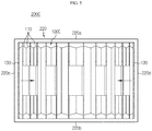
- FIG. 3 is a front view schematically showing some components of the battery module according to an embodiment of the present disclosure.
- a battery module 200 includes a cell assembly 100, a module housing 220 and an end frame 230.
- the cell assembly 100 may include at least three battery cells 110.
- the battery cell 110 may be a pouch-type battery cell 110.
- the pouch-type battery cell 110 may include an electrode assembly, an electrolyte and a pouch exterior case 115.
- the electrode assembly may be configured such that at least one positive electrode plate and at least one negative electrode plate are disposed with a separator interposed therebetween. More specifically, the electrode assembly may be classified into a wound type in which one positive electrode plate and one negative electrode plate are wound together with a separator, a stacking type in which a plurality of positive electrode plates and a plurality of negative electrode plates are alternately stacked with a separator interposed therebetween, and the like.
- the pouch exterior case 115 may be configured to have an outer insulating layer, a metal layer and an inner adhesive layer.
- the pouch exterior case 115 may be configured to include a metal thin film, for example an aluminum thin film, in order to protect inner components such as the electrode assembly and the electrolyte, to enhance electrochemical properties by the electrode assembly and the electrolyte, and to improve heat dissipation.
- the aluminum thin film may be interposed between insulating layers made of an insulating material so as to secure electrical insulation with components inside the battery cell 110 such as the electrode assembly and the electrolyte or with other components outside the battery cell 110.
- the pouch exterior case 115 may be composed of two pouches, at least one of which may have a concave inner space formed therein.
- the electrode assembly may be accommodated in the inner space of the pouch.
- sealing portions are provided at outer circumferential surfaces of two pouches, and the sealing portions are fused to each other to seal the inner space in which the electrode assembly is accommodated.
- the exterior case 115 may have an accommodation portion 115c in which the electrode assembly and the electrolyte are accommodated.
- Each pouch-type battery cell 110 may include an electrode lead 111, and the electrode lead 111 may include a positive electrode lead and a negative electrode lead.
- the electrode lead 111 may be configured to protrude forward or rearward from the sealing portion located at the outer circumference of the front or rear side of the pouch exterior case 115.
- the electrode lead 111 may serve as an electrode terminal of the battery cell 110.
- one electrode lead 111 may be configured to protrude forward from the battery cell 110, and the other electrode lead 111 may configured to protrude rearward from the battery cell 110.
- a plurality of pouch-type battery cells 110 may be included in the battery module 200 and arranged to be stacked in at least one direction.
- a plurality of pouch-type battery cells 110 may be stacked in a right and left direction.
- each pouch-type battery cells 110 may be disposed to stand approximately perpendicular to the ground, when being observed in the F direction, such that two broad surfaces are located at right and left sides, respectively, and the sealing portions are located at upper, lower, front and rear sides.
- each battery cell 110 may be configured to stand in an upper and lower direction.
- directions such as front, rear, left, right, upper and lower directions used herein may be changed depending on the position of an observer or the shape of an object.
- directions are classified into front, rear, left, right, upper and lower directions, based on the F direction.
- At least one battery cell 110 located at an inner side in the stacking direction W of the battery cells 110 may have a greater thickness Z in the stacking direction (the lateral direction) than a battery cell 110 located at an outer side.
- the thickness Z means a thickness Z in the lateral direction of the accommodation portion 115c ( FIG. 2 ) of the battery cell 110 in which the electrode assembly and the electrolyte of the battery cell 110 are accommodated.
- a battery cell 110 adjacent to an innermost side may have a greater thickness Z in the lateral direction than a battery cell 110 located at an outer side.
- the battery cell 110 located at the innermost side may have the greatest thickness Z in the lateral direction.
- the thickness Z of the battery cells 110 in the stacking direction W of the battery cells 110 may be gradually increased from the battery cell 110 located at the outermost side to the battery cell 110 located at the innermost side.
- the cell assembly 100 includes 12 battery cells 110.
- the twelve battery cells 110 two battery cells 110a located at the innermost side are formed to have a greater thickness Z in the lateral direction than the other battery cells 110.
- a gap is generated at a boundary surface P between the battery cells 110, and thus heat resistance may be generated on the boundary surface P.
- the battery module 200 of the present disclosure has a structure in which a battery cell 110 located at an inner side in the stacking direction of the battery cells 110 is formed to have a greater thickness Z in the stacking direction than a battery cell 110 located at an outer side, it is possible to reduce the frequency that the boundary surface P is formed between the battery cells 110 inside the cell assembly 100. That is, the boundary surface P is formed less between the battery cells 110 from the outer side of the cell assembly 100 toward the inner side of the cell assembly 100.
- the design capacity of the battery module 200 when the design capacity of the battery module 200 is changed, it is possible to perform the design change easily by adding required battery cells 110 or removing unnecessary battery cells 110, as compared with a cell assembly 100 having one large battery cell 110.
- the maintenance is convenient and the maintenance cost may be reduced.
- At least one battery cell 110 located at the inner side in the stacking direction may have a larger battery capacity than the battery cell 110 located at the outer side.
- at least one battery cell 110 located at the inner side may include the exterior case 115 of a larger capacity capable of accommodating the electrode assembly and electrolyte than the battery cell 110 located at the outer side.
- the battery cell 110 located at the inner side may accommodate greater electrode assembly and more electrolyte in the exterior case 115 than the battery cell 110 adjacent to the outer side.
- the energy capacity per volume of the cell assembly 100 may be similar at both the inner region and the outer region of the cell assembly 100.
- the configuration of the pouch-type battery cell 110 described above is obvious to those skilled in the art and thus will not be described in detail here.
- the cell assembly 100 according to the present disclosure may employ various kinds of battery cells (secondary batteries) known at the time of filing of this application.
- the module housing 220 may protect the internal structure of the battery module 200 from an external impact or prevent foreign substances from entering the battery module 200. Accordingly, the module housing 220 provides structural stability to the battery module 200 and protects the components accommodated therein, such as the cell assembly 100, from other external physical factors such as impacts and substances. To this end, the module housing 220 may be made of a metal such as steel or aluminum.
- the heat generated in the cell assembly 100 may be effectively discharged out of the module housing 220 by means of the high thermal conductivity of aluminum.
- module housing 220 may include at least one sidewall 220a, 220b, 220c, 220d.
- the sidewalls 220a, 220b, 220c, 220d may be connected to each other.
- the sidewalls 220a, 220b, 220c, 220d may include an upper wall 220a, a lower wall 220b, a left sidewall 220c and a right sidewall 220d based on the cell assembly 100, and the walls 220a, 220b, 220c, 220d may be connected to each other.
- the module housing 220 may have an inner space defined by the sidewalls 220a, 220b, 220c, 220d to accommodate the cell assembly 100 therein.
- the inner space may have an internal structure corresponding to the outer shape of the cell assembly 100.
- the upper walls 220 and the lower wall 220b of the module housing 220 may be perpendicularly connected to the left sidewall 220c and the right sidewall 220d so that the module housing 220 may accommodate the cell assembly 100 having a substantially rectangular parallelepiped shape.
- the inner space may be provided such that at least one of the upper wall 220a, the lower wall 220b, the left sidewall 220c and the right sidewall 220d of the module housing 220 contacts at least one side surface of the cell assembly 100. That is, as the area where the walls 220a, 220b, 220c, 220d of the module housing 220 directly contact the outer surfaces of the cell assembly 100 is greater, the heat generated in the cell assembly 100 may be effectively conducted to the module housing 220.
- the upper wall 220a, the lower wall 220b, the left side wall 220c and the right side wall 220d may be formed to contact an upper surface, a lower side, a left side surface and a right side surface of the cell assembly 100 .
- the module housing 220 may be configured using a mono frame in which the upper wall 220a, the lower wall 220b, the left sidewall 220c and the right sidewall 220d are provided in an integrated form.
- the integrated form means one body formed by a casting method or the like.
- both ends of the upper wall 220a, the lower wall 220b, the left sidewall 220c and the right sidewall 220d may be connected to each other.
- the module housing 220 may have a rectangular tubular shape that is opened in a front and rear direction, where both ends of the upper wall 220a, the lower wall 220b, the left side wall 220c and the right side wall 220d are connected to each other.
- the module housing 220 is formed to surround the side surfaces of the cell assembly 100, thereby effectively dissipating the heat generated in the cell assembly 100 when the battery module 200 is charged or discharged.
- the end frame 230 may include a body frame 232 and a bonding plate 236.
- the body frame 232 may include a main wall 232a. That is, the main wall 232a may have a plate shape upright in the vertical direction. Also, the main wall 232a may have a module terminal (not shown) to establish an electrical connection between the cell assembly 100 and an external device.
- the body frame 232 may have at least one sidewall 233 extending from an outer periphery of the main wall 232a toward the module housing 220.
- the body frame 232 may include an upper sidewall 233a, a lower sidewall 233b, a left sidewall 233c and a right sidewall 233d based on the center of the main wall 232a. Further, the sidewalls 233a, 233b, 233c, 233d may be connected to each other.
- the body frame 232 may protect the battery module 200 from external impacts. Accordingly, the body frame 232 gives structural stability to the battery module 200 and protects components accommodated therein, such as the cell assembly 100, from other external physical factors such as impacts and substances. To this end, the body frame 232 may be made of a metal material such as steel or aluminum.
- one side portion of the bonding plate 236 may be fixed to the sidewall 233 of the body frame 232. That is, the bonding plate 236 may be divided into a front portion and a rear portion based on a lateral line of a predetermined position on the bonding plate 236, and the front portion or the rear portion of the bonding plate 236 may be coupled and fixed to an outer surface of the sidewall 233 of the body frame 232.
- the bonding plate 236 may be configured such that the rear portion is coupled to the front end of the module housing 220 when the front portion of the bonding plate 236 is coupled and fixed to the outer surface of the sidewall 233 of the body frame 232. Conversely, when the rear portion of the bonding plate 236 is coupled and fixed to the outer surface of the sidewall 233 of the body frame 232, the front portion may be coupled to the rear end of the module housing 220.
- the bonding plate 236 may be made of a metal material such as steel or aluminum.
- FIG. 4 is a front view schematically showing some components of a battery module according to another embodiment of the present disclosure.
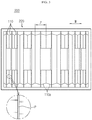
- a battery module 200B may be configured such that among the at least three battery cells 110 provided in the cell assembly 100B, the height in the vertical direction H of a battery cell 110 located at the inner side is greater than the height of the battery cell 110 located at the outer side.
- two battery cells 110a located at the innermost side may be formed to have the greatest height in the vertical direction H
- four battery cell 110b adjacent to the battery cells 110a may be formed to have a second height
- six battery cells 110c positioned at the outer side may be formed to have the lowest height in the vertical direction H.
- the height in the vertical direction H of the battery cell 110 located at the inside of the cell assembly 100B is relatively higher than that of the remaining battery cells 110, it is possible to effectively increase the outer area of the battery cell 110 located at the inner side, and it is possible to increase the area of the outer surface exposed to the outside rather than the bonded surface between the battery cells 110, thereby increasing the heat dissipation amount compared to the battery cells 110 located a relatively outer side in the stacking direction .
- FIG. 5 is a front view schematically showing some components of a battery module according to still another embodiment of the present disclosure.
- the sidewalls 220a, 220b, 220c, 220d of the module housing 220 may be configured to compress the battery cells 110 inwards in the stacking direction to prevent a gap from being generated between the battery cells 110.
- the battery module 200C of FIG. 5 may further include an elastic member 130 in the inner space accommodating the cell assembly 100C of the module housing 220, as compared with the battery module 200 of FIG. 3 .
- the elastic member 130 may have an elastic material that is excellent in heat dissipation property and has a volume easily increasing and decreasing depending on an external pressure.
- the elastic member 130 may be a silicon pad.
- the elastic member 130 may be respectively positioned at both side ends of the plurality of battery cells 110 in the stacking direction.
- two elastic members 130 may be respectively positioned on the inner surfaces of the left sidewall 220c and the right sidewall 220d located at both sides of the battery cell 110 in the lateral direction.
- the elastic member 130 since the elastic member 130 is provided inside the module housing 220, the elastic member 130 may elastically compress the cell assembly 100C, thereby reducing the gap between the battery cells 110 and thus greatly reducing the heat resistance at the boundary surface.
- FIG. 6 is a front view schematically showing some components of a battery module according to still another embodiment of the present disclosure.
- the outer surfaces of the battery cells 110 may be bonded to each other, compared to the cell assembly 100 of FIG. 3 .
- an adhesive layer 117 may be formed between the plurality of battery cells 110 of the cell assembly 100D to prevent a gap from being generated between the battery cells 110.
- the adhesive layer 117 is preferably made of a material having excellent heat dissipation, and may be, for example, a hardening grease or a glue.
- the adhesive layer 117 is not limited to the adhesive material, and the adhesive layer 117 may be made using a known heat-dissipative adhesive material.
- the adhesive layer 117 is formed between the battery cells 110 not to generate a gap between the battery cells 110, the heat resistance of the boundary surface between the battery cells 110 may be greatly reduced, and the battery cells 110 are restrained to each other so that their stacking arrangement is not disturbed while preventing the battery cell 110 from moving due to an external impact, thereby improving the stability and durability of the cell assembly 100D.
- FIG. 7 is a front view schematically showing some components of a battery module according to still another embodiment of the present disclosure.
- the exterior cases 115 of the battery cells 110 may be integrated and connected to each other, compared with the cell assembly 100 of FIG. 3 .
- the exterior cases 115 of the battery cells 110 may have shaped such that their portions 115a contacting each other connected to each other. That is, the exterior cases 115 of the at least three battery cells 110 provided in the cell assembly 100E may be formed as an integrated exterior case 115 having a plurality of accommodation portions capable of accommodating an electrode assembly and an electrolyte.
- the exterior cases 115 of twelve battery cells 110 may be integrally formed. That is, the twelve battery cells 110 may be formed to have an integrated exterior case 115.
- the cell assembly 100E having the outer case 115 integrally formed it is possible to minimize the heat resistance generated on the boundary surface because there is no gap between the battery cells 110.
- the size of the exterior case 115 of the cell assembly 100E may be effectively reduced.
- FIG. 8 is a front view schematically showing some components of a battery module according to still another embodiment of the present disclosure.
- the cell assembly 100F of the battery module 200F may further include a cooling fin 119.
- the cooling fin 119 may be added to contact the battery cell 110 located at the inner side, among the at least three battery cells 110.
- the cooling fin 119 may have various sizes.
- the cooling fin 119a positioned to contact the battery cell 110 located at the inner side among the battery cells 110 may have a greater outer surface than the cooling fin 119b positioned to contact the battery cell 110 located at the outer side. That is, the cooling fin 119a positioned to contact the battery cell 110 located at the inner side may be set to have a larger heat dissipation amount than the cooling fin 119b positioned to contact the battery cell 110 located at the outer side.
- the cooling fin 119 may be configured to contact the battery cells 110 located at the inner side in the stacking direction, instead of contacting all of the battery cells 110. In this case, the number of the cooling fins 119 may be decreased, thereby not only reducing the manufacturing cost of the battery module 200F but also easily reducing the weight of the battery module 200F.
- three cooling fins 119 may be added between the battery cells 110 located at the inner side in the cell assembly 100F. Also, among the three cooling fins 119, the cooling fin 119a located at the center may be formed to have a longer vertical length than the remaining cooling fins 119b.
- the cooling fin 119 is added to contact the battery cell 110 located at the inner side, the heat dissipation amount of the battery cell 110 located at the inner side where the heat island is likely to occur may be effectively increased. Accordingly, the heat balance of all battery cells 110 may be properly maintained and the performance and life characteristics of the battery module 200F may be effectively enhanced.
- FIG. 9 is a front view schematically showing some components of a battery module according to still another embodiment of the present disclosure.
- the electrode lead 111a of at least one battery cell 110G located at the inner side in the stacking direction of the battery cells 110G may have a greater outer area than the electrode lead 111c of the battery cell 110G located at the outer side.
- the electrode lead 111a of the at least one battery cell 110G located at the inner side in the stacking direction of the battery cells 110G may be formed to have a greater vertical length than the electrode lead 111c of the battery cell 110G located at the outer side.
- the electrode leads 111a of the battery cells 110a located at the innermost side among the twelve battery cells 110G may have the widest outer area. Further, the vertical lengths of the electrode leads 111 of the twelve battery cells 110c may be gradually increased from the battery cell 110c located at the outermost side to the battery cell 110a located at the innermost side in the stacking direction.
- the electrode leads 111a of the two battery cells 110a located at the innermost side among the twelve battery cells 110G may be formed to have the longest vertical length
- the electrode leads 111b of the four battery cells 110b located adjacent to the two battery cells 110a may be formed to have the second longest vertical length
- the electrode leads 111c of the six battery cells 110c located at the outer sides may be formed to have the shortest vertical length.
- the heat dissipation amount of the battery cell 110G may be increased as the outer surface of the electrode lead 111 becomes larger, the heat accumulation is most likely to be generated in the battery cell 110G located at the inner side, so the battery cell 110a may be formed to have a wider outer surface so that the heat dissipation amount is increased.
- the electrode lead 111 of the battery cell 110G located at the inner side of the cell assembly 100G has a relatively wider outer surface, the heat dissipation amount of the battery cell 110G located at the inner side may be effectively increased, and also the synergistic effect may be exerted in addition to the heat dissipation effect of the battery cell 110G located at the inner side and having a relatively greater thickness.
- FIG. 10 is a partial plane view showing battery cells of a battery module according to still another embodiment of the present disclosure.
- the thickness T1 of the electrode lead 111a of at least one battery cell 110H located at the inner (central) side in the stacking direction of the battery cells 110H may be greater than that of the electrode lead 111c of the battery cell 110H located at the outer side.
- the thickness T1 of the electrode leads 111 of the twelve battery cells 110H in the stacking direction may be different from each other. That is, among the twelve battery cells 110H, the electrode leads 111a of two battery cells 110a located at the innermost side may have a thickness T1 of 0.8 mm, the electrode leads 111b of the remaining four battery cells 110H adjacent to the inner side may have a thickness T2 of 0.6 mm, the electrode leads 111c of the six battery cells 110H located at the outer side may have a thickness T3 of 0.4 mm.
- the electrode lead 111 of the battery cell 110a located at the inner side is formed thicker than the electrode lead 111 of the battery cell 110c located at the outer side, it is possible to increase the heat dissipation amount through the electrode lead 111 and reduce the electric resistance heat generated at the electrode lead 111, thereby effectively reducing the heat accumulation of the battery cell 110H located at the inner side.
- a battery pack (not shown) according to the present disclosure may include at least one battery module 200 according to the present disclosure. Further, the battery pack according to the present disclosure may further include, in addition to the battery module 200, a pack case for accommodating the battery module 200, and various devices for controlling charge and discharge of the battery module 200, for example a battery management system (BMS), a current sensor, a fuse and the like.
- BMS battery management system
- the battery pack according to the present disclosure may be applied to a vehicle such as an electric vehicle and a hybrid electric vehicle.
- the vehicle according to the present disclosure may include the battery pack according to the present disclosure.
- Reference Signs 200 battery module 230: end frame 100: cell assembly 110: battery cell 111: electrode lead 220: module housing 117: adhesive layer 119: cooling fin
- the present disclosure relates to a battery module and a battery pack, which include a plurality of battery cells with different sizes. Also, the present disclosure is applicable to industries related to electronic devices or vehicles, which include the battery pack.
Landscapes
- Chemical & Material Sciences (AREA)
- Chemical Kinetics & Catalysis (AREA)
- Electrochemistry (AREA)
- General Chemical & Material Sciences (AREA)
- Engineering & Computer Science (AREA)
- Manufacturing & Machinery (AREA)
- Inorganic Chemistry (AREA)
- Secondary Cells (AREA)
- Battery Mounting, Suspending (AREA)
Abstract
Description
- The present disclosure relates to a battery module having a plurality of battery cells with various sizes and a battery pack including the battery module, and more particularly, to a battery module for improving heat balance of a cell assembly provided in the battery module.
- The present application claims priority to Korean Patent Application No.
10-2018-0039232 filed on April 4, 2018 - Secondary batteries currently commercialized include nickel cadmium batteries, nickel hydrogen batteries, nickel zinc batteries, lithium secondary batteries and so on. Among them, the lithium secondary batteries are more highlighted in comparison to nickel-based secondary batteries due to advantages such as free charging and discharging, caused by substantially no memory effect, very low self-discharge rate, and high energy density.
- The secondary battery is easily applicable to various product groups and has electrical characteristics with high energy density. The secondary battery is applied not only to portable electronic devices but also to electric vehicles, hybrid electric vehicles or electric power storage devices, driven by electric driving sources.
- The secondary battery is attracting attention as a new energy source for eco-friendliness and energy efficiency due to not only a primary advantage of remarkably reducing the use of fossil fuels but also no generation of by-product during energy use.
- A battery pack applied to an electric vehicle or the like has a structure in which a plurality of battery modules, each having a plurality of battery cells, are connected to obtain a high output. In addition, each battery cell includes a positive electrode current collector, a negative electrode current collector, a separator, an active material and an electrolyte as an electrode assembly, and may be repeatedly charged and discharged by an electrochemical reaction between the components.
- Meanwhile, as the need for a large-capacity structure has recently increased along with the need for utilization as an energy storage source, there has been an increasing demand for a battery module having a plurality of secondary batteries connected in series and/or in parallel.
- Since the battery module is manufactured such that a plurality of secondary batteries are densely packed in a narrow space, it is important to easily release the heat generated from each battery cell to the outside.
- In other words, during the secondary battery charging or discharging process, heat is generated due to the electrochemical reaction. Thus, if the heat of the battery module generated during the charging and discharging process is not effectively removed, heat accumulation may occur. In addition, deterioration of the battery module may be accelerated and, in some cases, ignition or explosion may occur.
- Also, when a plurality of battery cells are mounted in one battery module, the density of the battery cells is very high due to space limitation. In addition, since the caloric value of the battery cell is proportional to the square of current, the temperature of the battery cell is likely to rise sharply during high-rate discharge. Particularly, the heat island phenomenon where heat is concentrated in an inner part (a central part) of a battery cell array mounted in the battery module is likely to occur.
- If the heat island phenomenon occurs in the long term, the cell performance of battery cells located in the inner region is deteriorated, and the output voltages of the battery cells electrically connected in parallel become uneven, thereby causing so-called cell imbalance phenomenon. As a result, in the conventional art, it is difficult for the battery module to exhibit high performance for a long time in the high-rate discharge. Accordingly, a technology capable of improving heat balance is needed to improve the performance and life characteristics of the battery module.
- The present disclosure is designed to solve the problems of the related art, and therefore the present disclosure is directed to providing a battery module, which may improve heat balance of a cell assembly.
- These and other objects and advantages of the present disclosure may be understood from the following detailed description and will become more fully apparent from the exemplary embodiments of the present disclosure. Also, it will be easily understood that the objects and advantages of the present disclosure may be realized by the means shown in the appended claims and combinations thereof.
- In one aspect of the present disclosure, there is provided a battery module, comprising:
- a cell assembly having at least three battery cells stacked in one direction, so that among the battery cells, at least one battery cell located at an inner side in the stacking direction of the battery cells has a greater thickness in the stacking direction than a battery cell located at an outer side; and
- a module housing having at least one sidewall and configured to accommodate the cell assembly in an inner space defined by the sidewall.
- Also, the thickness of the battery cells in the stacking direction may be gradually increased from a battery cell located at an outermost side in the stacking direction to a battery cell located at an innermost side.
- Moreover, in the battery cells, the at least one battery cell located at the inner side in the stacking direction may have a greater battery capacity than the battery cell located at the outer side.
- In addition, the sidewall of the module housing may be configured to compress the battery cells inwards in the stacking direction so that no gap is generated between the battery cells.
- Further, contact surfaces of the battery cells may be bonded to each other so that no gap is generated between the battery cells.
- Also, exterior cases of the battery cells may be integrated and connected to each other.
- Moreover, an electrode lead of the at least one battery cell located at the inner side in the stacking direction of the battery cells may have a greater outer area than an electrode lead of the battery cell located at the outer side.
- In addition, an electrode lead of the at least one battery cell located at the inner side in the stacking direction of the battery cells may have a greater thickness in the stacking direction of the battery cells than an electrode lead of the battery cell located at the outer side.
- Further, in another aspect of the present disclosure, there is also provided a battery pack, which includes at least one battery module as above.
- In addition, in another aspect of the present disclosure, there is also provided a vehicle, which includes the battery pack.
- According to one embodiment of the present disclosure, since a battery cell located at an inner side in the stacking direction of the battery cells is formed to have a greater thickness in the stacking direction than a battery cell located at an outer side, it is possible to reduce the frequency that a boundary surface is formed between the battery cells inside the cell assembly.
- Thus, since excessive heat accumulation in the battery cells located at the center of the cell assembly may be prevented, the heat balance of the entire battery cells may be properly maintained, and the performance and life characteristics of the battery module may be effectively enhanced.
- In addition, according to another embodiment of the present disclosure, since the vertical height of the battery cell located at an inner side of the cell assembly is relatively higher than that of the other battery cells, the outer surface area of the battery cells located in the cell assembly may be effectively increased. In particular, since the area of the outer surface exposed to the outside, rather than the bonded surface between the battery cells, may be increased, the heat dissipation amount may be increased compared to the battery cells located at a relatively outer side in the stacking direction. Accordingly, the heat balance of the cell assembly may be improved.
- Moreover, according to another embodiment of the present disclosure, as the elastic member is provided inside the module housing, the elastic member may flexibly compress the cell assembly, which reduces the gap between the battery cells, thereby greatly decreasing heat resistance. Accordingly, the heat dissipation characteristic of the cell assembly may be improved, and it is possible to improve the heat balance according to the cell thickness and exhibit synergistic effects.
- In addition, according to another embodiment of the present disclosure, since the adhesive layer is formed between the battery cells, a gap is not generated between the battery cells, thereby greatly reducing the heat resistance of the boundary surface. Moreover, since the battery cells are restrained to each other, the stacking arrangement is not disturbed, and the battery cells may be prevented from moving due to external impact, thereby improving the stability or durability of the cell assembly.
- Further, according to another embodiment of the present disclosure, in the cell assembly having an exterior case integrated formed, since a gap is not generated between battery cells, it is possible to minimize the heat resistance generated on the boundary surface. In addition, the size of the exterior case of the cell assembly may be reduced.
- Also, according to another embodiment of the present disclosure, since the outer surface of the electrode lead of the battery cell located inside the cell assembly is formed relatively wide, it is possible to effectively increase the heat dissipation amount of the battery cells located inside, and the heat dissipation effect and the synergy effect may be provided to the battery cells formed at the inner side and formed thickly.
- The accompanying drawings illustrate a preferred embodiment of the present disclosure and together with the foregoing disclosure, serve to provide further understanding of the technical features of the present disclosure, and thus, the present disclosure is not construed as being limited to the drawing.
-
FIG. 1 is a perspective view schematically showing a battery module according to an embodiment of the present disclosure. -
FIG. 2 is an exploded perspective view schematically showing components of the battery module according to an embodiment of the present disclosure. -
FIG. 3 is a front view schematically showing some components of the battery module according to an embodiment of the present disclosure. -
FIG. 4 is a front view schematically showing some components of a battery module according to another embodiment of the present disclosure. -
FIG. 5 is a front view schematically showing some components of a battery module according to still another embodiment of the present disclosure. -
FIG. 6 is a front view schematically showing some components of a battery module according to still another embodiment of the present disclosure. -
FIG. 7 is a front view schematically showing some components of a battery module according to still another embodiment of the present disclosure. -
FIG. 8 is a front view schematically showing some components of a battery module according to still another embodiment of the present disclosure. -
FIG. 9 is a front view schematically showing some components of a battery module according to still another embodiment of the present disclosure. -
FIG. 10 is a partial plane view showing battery cells of a battery module according to still another embodiment of the present disclosure. - Hereinafter, preferred embodiments of the present disclosure will be described in detail with reference to the accompanying drawings. Prior to the description, it should be understood that the terms used in the specification and the appended claims should not be construed as limited to general and dictionary meanings, but interpreted based on the meanings and concepts corresponding to technical aspects of the present disclosure on the basis of the principle that the inventor is allowed to define terms appropriately for the best explanation.
- Therefore, the description proposed herein is just a preferable example for the purpose of illustrations only, not intended to limit the scope of the disclosure, so it should be understood that other equivalents and modifications could be made thereto without departing from the scope of the disclosure.
-
FIG. 1 is a perspective view schematically showing a battery module according to an embodiment of the present disclosure.FIG. 2 is an exploded perspective view schematically showing components of the battery module according to an embodiment of the present disclosure. Also,FIG. 3 is a front view schematically showing some components of the battery module according to an embodiment of the present disclosure. - Referring to
FIGS. 1 to 3 , abattery module 200 according to an embodiment of the present disclosure includes acell assembly 100, amodule housing 220 and anend frame 230. - Here, the
cell assembly 100 may include at least threebattery cells 110. Also, thebattery cell 110 may be a pouch-type battery cell 110. In particular, the pouch-type battery cell 110 may include an electrode assembly, an electrolyte and apouch exterior case 115. - Here, the electrode assembly may be configured such that at least one positive electrode plate and at least one negative electrode plate are disposed with a separator interposed therebetween. More specifically, the electrode assembly may be classified into a wound type in which one positive electrode plate and one negative electrode plate are wound together with a separator, a stacking type in which a plurality of positive electrode plates and a plurality of negative electrode plates are alternately stacked with a separator interposed therebetween, and the like.
- Also, the
pouch exterior case 115 may be configured to have an outer insulating layer, a metal layer and an inner adhesive layer. Thepouch exterior case 115 may be configured to include a metal thin film, for example an aluminum thin film, in order to protect inner components such as the electrode assembly and the electrolyte, to enhance electrochemical properties by the electrode assembly and the electrolyte, and to improve heat dissipation. In addition, the aluminum thin film may be interposed between insulating layers made of an insulating material so as to secure electrical insulation with components inside thebattery cell 110 such as the electrode assembly and the electrolyte or with other components outside thebattery cell 110. - In particular, the
pouch exterior case 115 may be composed of two pouches, at least one of which may have a concave inner space formed therein. In addition, the electrode assembly may be accommodated in the inner space of the pouch. Also, sealing portions are provided at outer circumferential surfaces of two pouches, and the sealing portions are fused to each other to seal the inner space in which the electrode assembly is accommodated. Namely, theexterior case 115 may have anaccommodation portion 115c in which the electrode assembly and the electrolyte are accommodated. - Each pouch-
type battery cell 110 may include anelectrode lead 111, and theelectrode lead 111 may include a positive electrode lead and a negative electrode lead. - In more detail, the
electrode lead 111 may be configured to protrude forward or rearward from the sealing portion located at the outer circumference of the front or rear side of thepouch exterior case 115. In addition, theelectrode lead 111 may serve as an electrode terminal of thebattery cell 110. For example, as shown inFIG. 2 , oneelectrode lead 111 may be configured to protrude forward from thebattery cell 110, and theother electrode lead 111 may configured to protrude rearward from thebattery cell 110. - Thus, according to this configuration of the present disclosure, in one
battery cell 110, there is no interference between the positive electrode lead and the negative electrode lead, thereby widening the area of theelectrode lead 111. In addition, a welding process between the plurality of electrode leads 111 or between theelectrode lead 111 and a bus bar (not shown) may be performed more easily. - In addition, a plurality of pouch-
type battery cells 110 may be included in thebattery module 200 and arranged to be stacked in at least one direction. For example, as shown inFIG. 2 , a plurality of pouch-type battery cells 110 may be stacked in a right and left direction. At this time, each pouch-type battery cells 110 may be disposed to stand approximately perpendicular to the ground, when being observed in the F direction, such that two broad surfaces are located at right and left sides, respectively, and the sealing portions are located at upper, lower, front and rear sides. In other words, eachbattery cell 110 may be configured to stand in an upper and lower direction. - Meanwhile, the terms indicating directions such as front, rear, left, right, upper and lower directions used herein may be changed depending on the position of an observer or the shape of an object. For the sake of convenience of description, in the present specification, directions are classified into front, rear, left, right, upper and lower directions, based on the F direction.
- Further, among the
battery cells 110, at least onebattery cell 110 located at an inner side in the stacking direction W of thebattery cells 110 may have a greater thickness Z in the stacking direction (the lateral direction) than abattery cell 110 located at an outer side. Here, the thickness Z means a thickness Z in the lateral direction of theaccommodation portion 115c (FIG. 2 ) of thebattery cell 110 in which the electrode assembly and the electrolyte of thebattery cell 110 are accommodated. - Specifically, among the
battery cells 110, abattery cell 110 adjacent to an innermost side may have a greater thickness Z in the lateral direction than abattery cell 110 located at an outer side. In addition, among thebattery cells 110, thebattery cell 110 located at the innermost side may have the greatest thickness Z in the lateral direction. Further, the thickness Z of thebattery cells 110 in the stacking direction W of thebattery cells 110 may be gradually increased from thebattery cell 110 located at the outermost side to thebattery cell 110 located at the innermost side. - For example, as shown in
FIG. 3 , thecell assembly 100 includes 12battery cells 110. Among the twelvebattery cells 110, twobattery cells 110a located at the innermost side are formed to have a greater thickness Z in the lateral direction than theother battery cells 110. - Meanwhile, in the
battery module 200 having the plurality ofbattery cells 110, a gap is generated at a boundary surface P between thebattery cells 110, and thus heat resistance may be generated on the boundary surface P. - Thus, according to this configuration of the present disclosure, as the
battery module 200 of the present disclosure has a structure in which abattery cell 110 located at an inner side in the stacking direction of thebattery cells 110 is formed to have a greater thickness Z in the stacking direction than abattery cell 110 located at an outer side, it is possible to reduce the frequency that the boundary surface P is formed between thebattery cells 110 inside thecell assembly 100. That is, the boundary surface P is formed less between thebattery cells 110 from the outer side of thecell assembly 100 toward the inner side of thecell assembly 100. - Accordingly, it is possible to prevent heat from be excessively accumulated in the
battery cells 110 located at the center of thecell assembly 100, thereby properly maintaining the heat balance of theentire battery cells 110 and effectively improving the performance and life characteristics of thebattery module 200. - Further, in the case of the
cell assembly 100 having a plurality of thebattery cells 110 of various thickness Z, when the design capacity of thebattery module 200 is changed, it is possible to perform the design change easily by adding requiredbattery cells 110 or removingunnecessary battery cells 110, as compared with acell assembly 100 having onelarge battery cell 110. - In addition, in the case of the
cell assembly 100 having a plurality ofbattery cells 110 of various thickness Z, since it is possible to exchange only abattery cell 110 having a failure with anew battery cell 110 among the plurality ofbattery cells 110, the maintenance is convenient and the maintenance cost may be reduced. - Referring to
FIGS. 2 and3 again, among the plurality ofbattery cells 110, at least onebattery cell 110 located at the inner side in the stacking direction may have a larger battery capacity than thebattery cell 110 located at the outer side. In other words, at least onebattery cell 110 located at the inner side may include theexterior case 115 of a larger capacity capable of accommodating the electrode assembly and electrolyte than thebattery cell 110 located at the outer side. In other words, thebattery cell 110 located at the inner side may accommodate greater electrode assembly and more electrolyte in theexterior case 115 than thebattery cell 110 adjacent to the outer side. - Accordingly, the energy capacity per volume of the
cell assembly 100 may be similar at both the inner region and the outer region of thecell assembly 100. - The configuration of the pouch-
type battery cell 110 described above is obvious to those skilled in the art and thus will not be described in detail here. In addition, thecell assembly 100 according to the present disclosure may employ various kinds of battery cells (secondary batteries) known at the time of filing of this application. - Referring to
FIGS. 1 and2 again, themodule housing 220 may protect the internal structure of thebattery module 200 from an external impact or prevent foreign substances from entering thebattery module 200. Accordingly, themodule housing 220 provides structural stability to thebattery module 200 and protects the components accommodated therein, such as thecell assembly 100, from other external physical factors such as impacts and substances. To this end, themodule housing 220 may be made of a metal such as steel or aluminum. - In particular, when the
module housing 220 is made of a metal material including aluminum, the heat generated in thecell assembly 100 may be effectively discharged out of themodule housing 220 by means of the high thermal conductivity of aluminum. - In addition, the
module housing 220 may include at least onesidewall - Specifically, if a plurality of sidewalls 220a, 220b, 220c, 220d are provided, the sidewalls 220a, 220b, 220c, 220d may be connected to each other. For example, when viewed in the direction F, the sidewalls 220a, 220b, 220c, 220d may include an
upper wall 220a, alower wall 220b, aleft sidewall 220c and aright sidewall 220d based on thecell assembly 100, and thewalls - In addition, the
module housing 220 may have an inner space defined by the sidewalls 220a, 220b, 220c, 220d to accommodate thecell assembly 100 therein. Specifically, the inner space may have an internal structure corresponding to the outer shape of thecell assembly 100. - For example, as shown in
FIG. 2 , theupper walls 220 and thelower wall 220b of themodule housing 220 may be perpendicularly connected to theleft sidewall 220c and theright sidewall 220d so that themodule housing 220 may accommodate thecell assembly 100 having a substantially rectangular parallelepiped shape. - Further, the inner space may be provided such that at least one of the
upper wall 220a, thelower wall 220b, theleft sidewall 220c and theright sidewall 220d of themodule housing 220 contacts at least one side surface of thecell assembly 100. That is, as the area where thewalls module housing 220 directly contact the outer surfaces of thecell assembly 100 is greater, the heat generated in thecell assembly 100 may be effectively conducted to themodule housing 220. - For example, as shown in
FIG. 2 , in themodule housing 220, theupper wall 220a, thelower wall 220b, theleft side wall 220c and theright side wall 220d may be formed to contact an upper surface, a lower side, a left side surface and a right side surface of thecell assembly 100 . - More specifically, the
module housing 220 may be configured using a mono frame in which theupper wall 220a, thelower wall 220b, theleft sidewall 220c and theright sidewall 220d are provided in an integrated form. - Here, the integrated form means one body formed by a casting method or the like. Specifically, in the
module housing 220, both ends of theupper wall 220a, thelower wall 220b, theleft sidewall 220c and theright sidewall 220d may be connected to each other. - For example, as shown in
FIG. 2 , themodule housing 220 may have a rectangular tubular shape that is opened in a front and rear direction, where both ends of theupper wall 220a, thelower wall 220b, theleft side wall 220c and theright side wall 220d are connected to each other. - Thus, according to this configuration of the present disclosure, the
module housing 220 is formed to surround the side surfaces of thecell assembly 100, thereby effectively dissipating the heat generated in thecell assembly 100 when thebattery module 200 is charged or discharged. - Referring to
FIGS. 1 and2 again, theend frame 230 may include abody frame 232 and abonding plate 236. - Here, the
body frame 232 may include amain wall 232a. That is, themain wall 232a may have a plate shape upright in the vertical direction. Also, themain wall 232a may have a module terminal (not shown) to establish an electrical connection between thecell assembly 100 and an external device. - In addition, the
body frame 232 may have at least onesidewall 233 extending from an outer periphery of themain wall 232a toward themodule housing 220. - Specifically, when viewed in the direction F, the
body frame 232 may include anupper sidewall 233a, alower sidewall 233b, aleft sidewall 233c and aright sidewall 233d based on the center of themain wall 232a. Further, the sidewalls 233a, 233b, 233c, 233d may be connected to each other. - Moreover, the
body frame 232 may protect thebattery module 200 from external impacts. Accordingly, thebody frame 232 gives structural stability to thebattery module 200 and protects components accommodated therein, such as thecell assembly 100, from other external physical factors such as impacts and substances. To this end, thebody frame 232 may be made of a metal material such as steel or aluminum. - Further, one side portion of the
bonding plate 236 may be fixed to thesidewall 233 of thebody frame 232. That is, thebonding plate 236 may be divided into a front portion and a rear portion based on a lateral line of a predetermined position on thebonding plate 236, and the front portion or the rear portion of thebonding plate 236 may be coupled and fixed to an outer surface of thesidewall 233 of thebody frame 232. - In addition, the
bonding plate 236 may be configured such that the rear portion is coupled to the front end of themodule housing 220 when the front portion of thebonding plate 236 is coupled and fixed to the outer surface of thesidewall 233 of thebody frame 232. Conversely, when the rear portion of thebonding plate 236 is coupled and fixed to the outer surface of thesidewall 233 of thebody frame 232, the front portion may be coupled to the rear end of themodule housing 220. - Further, the
bonding plate 236 may be made of a metal material such as steel or aluminum. -
FIG. 4 is a front view schematically showing some components of a battery module according to another embodiment of the present disclosure. - Referring to
FIG. 4 , abattery module 200B according to another embodiment of the present invention may be configured such that among the at least threebattery cells 110 provided in the cell assembly 100B, the height in the vertical direction H of abattery cell 110 located at the inner side is greater than the height of thebattery cell 110 located at the outer side. - For example, as shown in
FIG. 4 , among twelvebattery cells 110, twobattery cells 110a located at the innermost side may be formed to have the greatest height in the vertical direction H, fourbattery cell 110b adjacent to thebattery cells 110a may be formed to have a second height, and sixbattery cells 110c positioned at the outer side may be formed to have the lowest height in the vertical direction H. - Thus, according to this configuration of the present disclosure, in the
battery module 200B according to another embodiment, since the height in the vertical direction H of thebattery cell 110 located at the inside of the cell assembly 100B is relatively higher than that of the remainingbattery cells 110, it is possible to effectively increase the outer area of thebattery cell 110 located at the inner side, and it is possible to increase the area of the outer surface exposed to the outside rather than the bonded surface between thebattery cells 110, thereby increasing the heat dissipation amount compared to thebattery cells 110 located a relatively outer side in the stacking direction . - Accordingly, it is possible to prevent heat from being excessively accumulated in the
battery cells 110 positioned at the center of the cell assembly 100B, thereby suitably maintaining the heat balance of allbattery cells 110 and effectively enhancing the performance and life characteristics of thebattery module 200B. -
FIG. 5 is a front view schematically showing some components of a battery module according to still another embodiment of the present disclosure. - Referring to
FIG. 5 , the sidewalls 220a, 220b, 220c, 220d of themodule housing 220 may be configured to compress thebattery cells 110 inwards in the stacking direction to prevent a gap from being generated between thebattery cells 110. At this time, the battery module 200C ofFIG. 5 may further include anelastic member 130 in the inner space accommodating the cell assembly 100C of themodule housing 220, as compared with thebattery module 200 ofFIG. 3 . - Specifically, the
elastic member 130 may have an elastic material that is excellent in heat dissipation property and has a volume easily increasing and decreasing depending on an external pressure. For example, theelastic member 130 may be a silicon pad. In addition, theelastic member 130 may be respectively positioned at both side ends of the plurality ofbattery cells 110 in the stacking direction. For example, as shown inFIG. 5 , twoelastic members 130 may be respectively positioned on the inner surfaces of theleft sidewall 220c and theright sidewall 220d located at both sides of thebattery cell 110 in the lateral direction. - Thus, according to this configuration of the present disclosure, since the
elastic member 130 is provided inside themodule housing 220, theelastic member 130 may elastically compress the cell assembly 100C, thereby reducing the gap between thebattery cells 110 and thus greatly reducing the heat resistance at the boundary surface. -
FIG. 6 is a front view schematically showing some components of a battery module according to still another embodiment of the present disclosure. - Referring to
FIG. 6 , in the cell assembly 100D of the battery module 200D according to still another embodiment, the outer surfaces of thebattery cells 110 may be bonded to each other, compared to thecell assembly 100 ofFIG. 3 . Specifically, anadhesive layer 117 may be formed between the plurality ofbattery cells 110 of the cell assembly 100D to prevent a gap from being generated between thebattery cells 110. - Further, the
adhesive layer 117 is preferably made of a material having excellent heat dissipation, and may be, for example, a hardening grease or a glue. However, theadhesive layer 117 is not limited to the adhesive material, and theadhesive layer 117 may be made using a known heat-dissipative adhesive material. - Thus, according to this configuration of the present disclosure, since the
adhesive layer 117 is formed between thebattery cells 110 not to generate a gap between thebattery cells 110, the heat resistance of the boundary surface between thebattery cells 110 may be greatly reduced, and thebattery cells 110 are restrained to each other so that their stacking arrangement is not disturbed while preventing thebattery cell 110 from moving due to an external impact, thereby improving the stability and durability of the cell assembly 100D. -
FIG. 7 is a front view schematically showing some components of a battery module according to still another embodiment of the present disclosure. - Referring to
FIG. 7 . In thecell assembly 100E of thebattery module 200E ofFIG. 7 , theexterior cases 115 of thebattery cells 110 may be integrated and connected to each other, compared with thecell assembly 100 ofFIG. 3 . In addition, theexterior cases 115 of thebattery cells 110 may have shaped such that theirportions 115a contacting each other connected to each other. That is, theexterior cases 115 of the at least threebattery cells 110 provided in thecell assembly 100E may be formed as an integratedexterior case 115 having a plurality of accommodation portions capable of accommodating an electrode assembly and an electrolyte. - For example, as shown in
FIG. 7 , theexterior cases 115 of twelvebattery cells 110 may be integrally formed. That is, the twelvebattery cells 110 may be formed to have an integratedexterior case 115. - Accordingly, according to this configuration of the present disclosure, in the
cell assembly 100E having theouter case 115 integrally formed, it is possible to minimize the heat resistance generated on the boundary surface because there is no gap between thebattery cells 110. In addition, the size of theexterior case 115 of thecell assembly 100E may be effectively reduced. -
FIG. 8 is a front view schematically showing some components of a battery module according to still another embodiment of the present disclosure. - Referring to
FIG. 8 , thecell assembly 100F of thebattery module 200F according to still another embodiment as shown inFIG. 8 may further include acooling fin 119. Specifically, the coolingfin 119 may be added to contact thebattery cell 110 located at the inner side, among the at least threebattery cells 110. - Also, the cooling
fin 119 may have various sizes. For example, the coolingfin 119a positioned to contact thebattery cell 110 located at the inner side among thebattery cells 110 may have a greater outer surface than the coolingfin 119b positioned to contact thebattery cell 110 located at the outer side. That is, the coolingfin 119a positioned to contact thebattery cell 110 located at the inner side may be set to have a larger heat dissipation amount than the coolingfin 119b positioned to contact thebattery cell 110 located at the outer side. - Further, the cooling
fin 119 may be configured to contact thebattery cells 110 located at the inner side in the stacking direction, instead of contacting all of thebattery cells 110. In this case, the number of the coolingfins 119 may be decreased, thereby not only reducing the manufacturing cost of thebattery module 200F but also easily reducing the weight of thebattery module 200F. - For example, as shown in
FIG. 8 , three coolingfins 119 may be added between thebattery cells 110 located at the inner side in thecell assembly 100F. Also, among the three coolingfins 119, the coolingfin 119a located at the center may be formed to have a longer vertical length than the remainingcooling fins 119b. - Thus, according to this configuration of the present disclosure, if the cooling
fin 119 is added to contact thebattery cell 110 located at the inner side, the heat dissipation amount of thebattery cell 110 located at the inner side where the heat island is likely to occur may be effectively increased. Accordingly, the heat balance of allbattery cells 110 may be properly maintained and the performance and life characteristics of thebattery module 200F may be effectively enhanced. -
FIG. 9 is a front view schematically showing some components of a battery module according to still another embodiment of the present disclosure. - Referring to
FIG. 9 , in thecell assembly 100G of thebattery module 200G according to still another embodiment, theelectrode lead 111a of at least onebattery cell 110G located at the inner side in the stacking direction of thebattery cells 110G may have a greater outer area than theelectrode lead 111c of thebattery cell 110G located at the outer side. - In addition, the
electrode lead 111a of the at least onebattery cell 110G located at the inner side in the stacking direction of thebattery cells 110G may be formed to have a greater vertical length than theelectrode lead 111c of thebattery cell 110G located at the outer side. - For example, as shown in
FIG. 9 , the electrode leads 111a of thebattery cells 110a located at the innermost side among the twelvebattery cells 110G may have the widest outer area. Further, the vertical lengths of the electrode leads 111 of the twelvebattery cells 110c may be gradually increased from thebattery cell 110c located at the outermost side to thebattery cell 110a located at the innermost side in the stacking direction. - Specifically, as shown in
FIG. 9 , the electrode leads 111a of the twobattery cells 110a located at the innermost side among the twelvebattery cells 110G may be formed to have the longest vertical length, the electrode leads 111b of the fourbattery cells 110b located adjacent to the twobattery cells 110a may be formed to have the second longest vertical length, and the electrode leads 111c of the sixbattery cells 110c located at the outer sides may be formed to have the shortest vertical length. - That is, since the heat dissipation amount of the
battery cell 110G may be increased as the outer surface of theelectrode lead 111 becomes larger, the heat accumulation is most likely to be generated in thebattery cell 110G located at the inner side, so thebattery cell 110a may be formed to have a wider outer surface so that the heat dissipation amount is increased. - Thus, according to this configuration of the present disclosure, since the
electrode lead 111 of thebattery cell 110G located at the inner side of thecell assembly 100G has a relatively wider outer surface, the heat dissipation amount of thebattery cell 110G located at the inner side may be effectively increased, and also the synergistic effect may be exerted in addition to the heat dissipation effect of thebattery cell 110G located at the inner side and having a relatively greater thickness. -
FIG. 10 is a partial plane view showing battery cells of a battery module according to still another embodiment of the present disclosure. - Referring to
FIG. 10 , in thecell assembly 100H of thebattery module 200H according to still another embodiment of the present disclosure, the thickness T1 of theelectrode lead 111a of at least onebattery cell 110H located at the inner (central) side in the stacking direction of thebattery cells 110H may be greater than that of theelectrode lead 111c of thebattery cell 110H located at the outer side. - For example, as shown
FIG. 10 , the thickness T1 of the electrode leads 111 of the twelvebattery cells 110H in the stacking direction may be different from each other. That is, among the twelvebattery cells 110H, the electrode leads 111a of twobattery cells 110a located at the innermost side may have a thickness T1 of 0.8 mm, the electrode leads 111b of the remaining fourbattery cells 110H adjacent to the inner side may have a thickness T2 of 0.6 mm, the electrode leads 111c of the sixbattery cells 110H located at the outer side may have a thickness T3 of 0.4 mm. - Thus, according to this configuration of the present disclosure, since the
electrode lead 111 of thebattery cell 110a located at the inner side is formed thicker than theelectrode lead 111 of thebattery cell 110c located at the outer side, it is possible to increase the heat dissipation amount through theelectrode lead 111 and reduce the electric resistance heat generated at theelectrode lead 111, thereby effectively reducing the heat accumulation of thebattery cell 110H located at the inner side. - In addition, a battery pack (not shown) according to the present disclosure may include at least one
battery module 200 according to the present disclosure. Further, the battery pack according to the present disclosure may further include, in addition to thebattery module 200, a pack case for accommodating thebattery module 200, and various devices for controlling charge and discharge of thebattery module 200, for example a battery management system (BMS), a current sensor, a fuse and the like. - In addition, the battery pack according to the present disclosure may be applied to a vehicle such as an electric vehicle and a hybrid electric vehicle. In other words, the vehicle according to the present disclosure may include the battery pack according to the present disclosure.
- Meanwhile, even though the terms indicating directions such as upper, lower, left, right, front and rear directions are used in the specification, it is obvious to those skilled in the art that these merely represent relative positions for convenience in explanation and may vary based on a position of an observer or an object.
- The present disclosure has been described in detail. However, it should be understood that the detailed description and specific examples, while indicating preferred embodiments of the disclosure, are given by way of illustration only, since various changes and modifications within the scope of the disclosure will become apparent to those skilled in the art from this detailed description.
Reference Signs 200: battery module 230: end frame 100: cell assembly 110: battery cell 111: electrode lead 220: module housing 117: adhesive layer 119: cooling fin - The present disclosure relates to a battery module and a battery pack, which include a plurality of battery cells with different sizes. Also, the present disclosure is applicable to industries related to electronic devices or vehicles, which include the battery pack.
Claims (10)
- A battery module, comprising:a cell assembly having at least three battery cells stacked in one direction, so that among the battery cells, at least one battery cell located at an inner side in the stacking direction of the battery cells has a greater thickness in the stacking direction than a battery cell located at an outer side; anda module housing having at least one sidewall and configured to accommodate the cell assembly in an inner space defined by the sidewall.
- The battery module according to claim 1,
wherein the thickness of the battery cells in the stacking direction is gradually increased from a battery cell located at an outermost side in the stacking direction to a battery cell located at an innermost side. - The battery module according to claim 1,
wherein in the battery cells, the at least one battery cell located at the inner side in the stacking direction has a greater battery capacity than the battery cell located at the outer side. - The battery module according to claim 1,
wherein the sidewall of the module housing is configured to compress the battery cells inwards in the stacking direction so that no gap is generated between the battery cells. - The battery module according to claim 1,
wherein contact surfaces of the battery cells are bonded to each other so that no gap is generated between the battery cells. - The battery module according to claim 1,
wherein exterior cases of the battery cells are integrated and connected to each other. - The battery module according to claim 1,
wherein an electrode lead of the at least one battery cell located at the inner side in the stacking direction of the battery cells has a greater outer area than an electrode lead of the battery cell located at the outer side. - The battery module according to claim 1,
wherein an electrode lead of the at least one battery cell located at the inner side in the stacking direction of the battery cells has a greater thickness in the stacking direction of the battery cells than an electrode lead of the battery cell located at the outer side. - A battery pack, comprising at least one battery module according to any one of claims 1 to 8.
- A vehicle, comprising the battery pack according to claim 9.
Applications Claiming Priority (2)
| Application Number | Priority Date | Filing Date | Title |
|---|---|---|---|
| KR1020180039232A KR102312416B1 (en) | 2018-04-04 | 2018-04-04 | Battery Module |
| PCT/KR2019/001994 WO2019194413A1 (en) | 2018-04-04 | 2019-02-19 | Battery module |
Publications (2)
| Publication Number | Publication Date |
|---|---|
| EP3686954A1 true EP3686954A1 (en) | 2020-07-29 |
| EP3686954A4 EP3686954A4 (en) | 2021-02-17 |
Family
ID=68101060
Family Applications (1)
| Application Number | Title | Priority Date | Filing Date |
|---|---|---|---|
| EP19780914.8A Pending EP3686954A4 (en) | 2018-04-04 | 2019-02-19 | BATTERY MODULE |
Country Status (6)
| Country | Link |
|---|---|
| US (1) | US11923523B2 (en) |
| EP (1) | EP3686954A4 (en) |
| JP (1) | JP7062192B2 (en) |
| KR (1) | KR102312416B1 (en) |
| CN (1) | CN111418085B (en) |
| WO (1) | WO2019194413A1 (en) |
Families Citing this family (14)
| Publication number | Priority date | Publication date | Assignee | Title |
|---|---|---|---|---|
| DE102019207356A1 (en) * | 2019-05-20 | 2020-11-26 | Audi Ag | Module housing, battery module, high-voltage battery, motor vehicle and method for introducing a heat-conducting medium between a battery module and a cooling floor |
| KR102811566B1 (en) | 2019-11-15 | 2025-05-22 | 주식회사 엘지에너지솔루션 | High voltage battery module comprising external bridge busbar |
| CN113594636B (en) | 2020-04-30 | 2024-10-18 | 宁德时代新能源科技股份有限公司 | Battery, device, and battery manufacturing method and equipment |
| WO2022021135A1 (en) | 2020-07-29 | 2022-02-03 | 宁德时代新能源科技股份有限公司 | Battery module, battery pack, apparatus, and method and device for manufacturing battery module |
| WO2022067808A1 (en) * | 2020-09-30 | 2022-04-07 | 宁德时代新能源科技股份有限公司 | Battery, device, and battery fabrication method and fabrication apparatus |
| JP7674361B2 (en) | 2020-09-30 | 2025-05-09 | 香港時代新能源科技有限公司 | Battery, device, battery manufacturing method and manufacturing device |
| CN115943522B (en) | 2020-09-30 | 2025-02-18 | 宁德时代新能源科技股份有限公司 | Battery, device, method for preparing battery, and device for preparing battery |
| KR102900267B1 (en) | 2020-10-08 | 2025-12-12 | 주식회사 엘지에너지솔루션 | Battery Module, Battery Rack, and Energy Storage System |
| WO2022104547A1 (en) | 2020-11-17 | 2022-05-27 | 宁德时代新能源科技股份有限公司 | Battery, device using battery, and method and device for preparing battery |
| WO2022133959A1 (en) | 2020-12-24 | 2022-06-30 | 宁德时代新能源科技股份有限公司 | Battery module and manufacturing method and device therefor, and battery pack and electrical apparatus |
| CN113363673B (en) * | 2021-06-28 | 2024-03-12 | 东莞新能安科技有限公司 | Battery modules and electronic devices using them |
| US20240088519A1 (en) * | 2021-10-25 | 2024-03-14 | Lg Energy Solution, Ltd. | Lithium secondary battery having ignition suppression structure |
| CN115032550A (en) * | 2022-06-02 | 2022-09-09 | 远景动力技术(江苏)有限公司 | Module voltage acquisition system and battery module |
| US20250316849A1 (en) | 2022-06-02 | 2025-10-09 | Envision Dynamics Technology (Jiangsu) Co., Ltd. | Wiring unit |
Family Cites Families (32)
| Publication number | Priority date | Publication date | Assignee | Title |
|---|---|---|---|---|
| KR980006597A (en) * | 1996-06-29 | 1998-03-30 | 김광호 | Nickel-zinc module battery |
| US6255015B1 (en) * | 1998-08-23 | 2001-07-03 | Ovonic Battery Company, Inc. | Monoblock battery assembly |
| JP3793908B2 (en) | 1998-11-24 | 2006-07-05 | 本田技研工業株式会社 | Rechargeable battery |
| KR100958647B1 (en) * | 2002-12-18 | 2010-05-20 | 삼성에스디아이 주식회사 | Pouch Type Secondary Battery Unit |
| JP4738730B2 (en) | 2003-04-21 | 2011-08-03 | 株式会社マキタ | Battery pack and battery pack |
| KR100560158B1 (en) * | 2003-09-29 | 2006-03-16 | 주식회사 코캄 | High safety lithium secondary battery and its manufacturing method |
| US7041408B1 (en) * | 2004-12-28 | 2006-05-09 | Utc Fuel Cells, Llc | Varied fuel cell oxidant flow channel depth resulting in fewer cooler plates |
| JP2009182001A (en) * | 2008-01-29 | 2009-08-13 | Nisshin Steel Co Ltd | Cell stack structure |
| KR101431278B1 (en) | 2008-12-19 | 2014-08-20 | 주식회사 엘지화학 | Secondary battery with improved uniformity of temperature distribution |
| JP2011044275A (en) | 2009-08-20 | 2011-03-03 | Sanyo Electric Co Ltd | Power supply device, and vehicle using the same |
| CN102473880A (en) * | 2010-02-10 | 2012-05-23 | 株式会社Lg化学 | Pouch type lithium secondary battery |
| JP5573319B2 (en) * | 2010-04-12 | 2014-08-20 | トヨタ自動車株式会社 | Power storage device and method for manufacturing power storage device |
| US9040187B2 (en) * | 2010-07-13 | 2015-05-26 | Apple, Inc. | Battery pack with cells of different capacities electrically coupled in parallel |
| DE102010047453A1 (en) * | 2010-10-04 | 2012-04-05 | Li-Tec Battery Gmbh | Housing for receiving a flat electrochemical cell |
| US9548476B2 (en) | 2010-12-20 | 2017-01-17 | Samsung Sdi Co., Ltd. | Multi-cell battery module with integral cooling and assembly aids |
| US9431686B2 (en) | 2011-02-28 | 2016-08-30 | Sanyo Electric Co., Ltd. | Cell module and manufacturing method for cell module |
| JP2013143185A (en) | 2012-01-06 | 2013-07-22 | Hitachi Ltd | Battery module and battery pack |
| JP2013157112A (en) | 2012-01-27 | 2013-08-15 | Toshiba Corp | Battery pack |
| KR101178152B1 (en) * | 2012-02-23 | 2012-08-29 | 주식회사 엘지화학 | Battery pack of novel structure |
| KR20130103286A (en) * | 2012-03-08 | 2013-09-23 | 주식회사 엘지화학 | Battery pack of stair-like structure |
| KR20130118716A (en) * | 2012-04-20 | 2013-10-30 | 주식회사 엘지화학 | Electrode assembly, battery cell and device comprising the same |
| DE102012207162A1 (en) | 2012-04-30 | 2013-10-31 | Robert Bosch Gmbh | Process for the production of Li-ion battery modules and a corresponding Li-ion battery module |
| KR20140100032A (en) * | 2013-02-05 | 2014-08-14 | 주식회사 엘지화학 | Battery Cell Having Structure of Steps-Formed |
| KR101783914B1 (en) * | 2013-10-22 | 2017-10-10 | 주식회사 엘지화학 | Pouch type secondary battery and battery pack including the same |
| CN105981197B (en) * | 2014-02-12 | 2019-08-30 | 远景Aesc 日本有限公司 | battery pack |
| KR101950031B1 (en) | 2015-09-21 | 2019-02-19 | 주식회사 엘지화학 | Battery Module Comprising Arrangement of a Plurality of Cooling Fins Having Different Thickness from each other |
| KR102051109B1 (en) | 2015-10-08 | 2019-12-02 | 주식회사 엘지화학 | Battery Module |
| KR20170072698A (en) * | 2015-12-17 | 2017-06-27 | 주식회사 엘지화학 | Battery module, battery pack comprising the battery module and plug in hybrid electric vehicle comprising the battery pack |
| KR102018721B1 (en) | 2016-05-31 | 2019-09-09 | 주식회사 엘지화학 | Battery module, battery pack comprising the battery module and vehicle comprising the battery pack |
| CN107799799A (en) * | 2016-09-05 | 2018-03-13 | 宁德新能源科技有限公司 | Battery bag |
| KR102556084B1 (en) | 2016-10-07 | 2023-07-17 | 삼성디스플레이 주식회사 | Display device capable of changing frame rate and operating method thereof |
| DE102016225184A1 (en) * | 2016-12-15 | 2018-06-21 | Robert Bosch Gmbh | Battery module with battery cell system and enclosure |
-
2018
- 2018-04-04 KR KR1020180039232A patent/KR102312416B1/en active Active
-
2019
- 2019-02-19 WO PCT/KR2019/001994 patent/WO2019194413A1/en not_active Ceased
- 2019-02-19 EP EP19780914.8A patent/EP3686954A4/en active Pending
- 2019-02-19 US US16/650,211 patent/US11923523B2/en active Active
- 2019-02-19 JP JP2020524702A patent/JP7062192B2/en active Active
- 2019-02-19 CN CN201980006045.0A patent/CN111418085B/en active Active
Also Published As
| Publication number | Publication date |
|---|---|
| US11923523B2 (en) | 2024-03-05 |
| KR102312416B1 (en) | 2021-10-12 |
| US20200266398A1 (en) | 2020-08-20 |
| CN111418085A (en) | 2020-07-14 |
| KR20190115940A (en) | 2019-10-14 |
| JP7062192B2 (en) | 2022-05-06 |
| CN111418085B (en) | 2023-01-17 |
| EP3686954A4 (en) | 2021-02-17 |
| WO2019194413A1 (en) | 2019-10-10 |
| JP2020527848A (en) | 2020-09-10 |
Similar Documents
| Publication | Publication Date | Title |
|---|---|---|
| US11923523B2 (en) | Battery module | |
| US20230335823A1 (en) | Battery module, and battery pack and vehicle comprising the same | |
| US10978759B2 (en) | Battery module having improved cooling performance | |
| JP5621111B2 (en) | Battery cell with improved thermal stability and medium- or large-sized battery module using the same | |
| EP3336957B1 (en) | Battery module, and battery pack and vehicle comprising the same | |
| US9865904B2 (en) | Battery cell of improved cooling efficiency | |
| KR101020587B1 (en) | Medium and large battery pack case with improved distribution uniformity of refrigerant flow rate | |
| JP5143909B2 (en) | Battery module and heat exchange member with excellent heat dissipation characteristics | |
| EP3358668B1 (en) | Battery module, battery pack and vehicle having same | |
| KR102184753B1 (en) | Battery module, battery pack comprising the battery module and vehicle comprising the battery pack | |
| US20190393567A1 (en) | Battery module | |
| EP3379639B1 (en) | Battery module, battery pack comprising same, and vehicle | |
| AU2020354063A1 (en) | Battery module, and battery rack and power storage device, each comprising same battery module | |
| KR20140039350A (en) | Battery module of improved cooling efficiency | |
| KR20140011439A (en) | Battery module having indirect air-cooling structure | |
| KR20120041142A (en) | Battery pack of excellent cooling efficiency | |
| KR20120053593A (en) | Battery pack of excellent cooling efficiency | |
| KR20140039349A (en) | Secondary battery of improved cooling efficiency | |
| KR101658589B1 (en) | Battery Module Having Metal Printed Circuit Board | |
| JP2003197278A (en) | Storage battery |
Legal Events
| Date | Code | Title | Description |
|---|---|---|---|
| STAA | Information on the status of an ep patent application or granted ep patent |
Free format text: STATUS: THE INTERNATIONAL PUBLICATION HAS BEEN MADE |
|
| PUAI | Public reference made under article 153(3) epc to a published international application that has entered the european phase |
Free format text: ORIGINAL CODE: 0009012 |
|
| STAA | Information on the status of an ep patent application or granted ep patent |
Free format text: STATUS: REQUEST FOR EXAMINATION WAS MADE |
|
| 17P | Request for examination filed |
Effective date: 20200423 |
|
| AK | Designated contracting states |
Kind code of ref document: A1 Designated state(s): AL AT BE BG CH CY CZ DE DK EE ES FI FR GB GR HR HU IE IS IT LI LT LU LV MC MK MT NL NO PL PT RO RS SE SI SK SM TR |
|
| AX | Request for extension of the european patent |
Extension state: BA ME |
|
| A4 | Supplementary search report drawn up and despatched |
Effective date: 20210115 |
|
| RIC1 | Information provided on ipc code assigned before grant |
Ipc: H01M 50/20 20210101AFI20210204BHEP Ipc: H01M 50/531 20210101ALI20210204BHEP |
|
| DAV | Request for validation of the european patent (deleted) | ||
| DAX | Request for extension of the european patent (deleted) | ||
| RAP1 | Party data changed (applicant data changed or rights of an application transferred) |
Owner name: LG ENERGY SOLUTION LTD. |
|
| RAP3 | Party data changed (applicant data changed or rights of an application transferred) |
Owner name: LG ENERGY SOLUTION, LTD. |
|
| STAA | Information on the status of an ep patent application or granted ep patent |
Free format text: STATUS: EXAMINATION IS IN PROGRESS |
|
| 17Q | First examination report despatched |
Effective date: 20221019 |