EP3686847A1 - Color gamut mapping method and device - Google Patents
Color gamut mapping method and device Download PDFInfo
- Publication number
- EP3686847A1 EP3686847A1 EP17925837.1A EP17925837A EP3686847A1 EP 3686847 A1 EP3686847 A1 EP 3686847A1 EP 17925837 A EP17925837 A EP 17925837A EP 3686847 A1 EP3686847 A1 EP 3686847A1
- Authority
- EP
- European Patent Office
- Prior art keywords
- color gamut
- point
- mapping
- color
- original
- Prior art date
- Legal status (The legal status is an assumption and is not a legal conclusion. Google has not performed a legal analysis and makes no representation as to the accuracy of the status listed.)
- Granted
Links
Images


Classifications
-
- H—ELECTRICITY
- H04—ELECTRIC COMMUNICATION TECHNIQUE
- H04N—PICTORIAL COMMUNICATION, e.g. TELEVISION
- H04N1/00—Scanning, transmission or reproduction of documents or the like, e.g. facsimile transmission; Details thereof
- H04N1/46—Colour picture communication systems
- H04N1/56—Processing of colour picture signals
- H04N1/60—Colour correction or control
- H04N1/6058—Reduction of colour to a range of reproducible colours, e.g. to ink- reproducible colour gamut
- H04N1/6061—Reduction of colour to a range of reproducible colours, e.g. to ink- reproducible colour gamut involving the consideration or construction of a gamut surface
-
- H—ELECTRICITY
- H04—ELECTRIC COMMUNICATION TECHNIQUE
- H04N—PICTORIAL COMMUNICATION, e.g. TELEVISION
- H04N1/00—Scanning, transmission or reproduction of documents or the like, e.g. facsimile transmission; Details thereof
- H04N1/46—Colour picture communication systems
- H04N1/56—Processing of colour picture signals
- H04N1/60—Colour correction or control
- H04N1/6058—Reduction of colour to a range of reproducible colours, e.g. to ink- reproducible colour gamut
-
- G—PHYSICS
- G06—COMPUTING OR CALCULATING; COUNTING
- G06T—IMAGE DATA PROCESSING OR GENERATION, IN GENERAL
- G06T5/00—Image enhancement or restoration
-
- G—PHYSICS
- G06—COMPUTING OR CALCULATING; COUNTING
- G06T—IMAGE DATA PROCESSING OR GENERATION, IN GENERAL
- G06T7/00—Image analysis
- G06T7/90—Determination of colour characteristics
-
- H—ELECTRICITY
- H04—ELECTRIC COMMUNICATION TECHNIQUE
- H04N—PICTORIAL COMMUNICATION, e.g. TELEVISION
- H04N1/00—Scanning, transmission or reproduction of documents or the like, e.g. facsimile transmission; Details thereof
- H04N1/46—Colour picture communication systems
- H04N1/56—Processing of colour picture signals
- H04N1/60—Colour correction or control
- H04N1/6075—Corrections to the hue
Definitions
- the disclosure relates to an image processing field, and more particularly to a color gamut mapping method and a color gamut mapping device.
- the HPMINDE algorithm commonly used at this stage for the hypo-color field problem, the colors outside the color gamut are all cut to the boundary of the target color gamut, the colors within the color gamut is directly outputted as itis.
- the color within the color gamut is outputted as it is, to ensure the accurate presenting of the color within the color gamut; the point outside the color gamut is mapped in the point direction toward the luminance axis, the color outside the region is mapped in the boundary of the color gamut successively, the area of the color gamut and the mapping line exit a bigger difference, and directly leads to poor mapping uniformity.
- the color gamut mapping algorithm especially in the process of larger color gamut mapping to the small color gamut, in common algorithm, for the color point located outside the small color gamut is mapping to some point along and toward the direction of the luminance axis, such as small area color gamut of ABHG projecting to the target area for AB, and a large area color gamut of EFJI projecting to the target area for EF, and EF is significantly shorter than AB, resulting in the problems of insufficient uniformity of the mapping, insufficient of the level of detail of the color, and so on.
- the technical problem solved by the invention is to provide a color gamut mapping algorithm, to obtain the coordinates of the mapping points by the proportion of the area, determine the mapping direction, and improve the uniformity and the level of detail of the color points on the boundary.
- the present invention provides a color gamut mapping method including the steps of:
- the present invention provides another color gamut mapping method including the steps of:
- the present invention provides a color gamut mapping device, the color gamut mapping device includes a controller and a data collector electrically connected to each other;
- the controller for determining a mapping target color gamut of an original color gamut in the same color gamut space, wherein, an area of the mapping target color gamut is smaller than an area of the original color gamut;
- the data collector for obtaining a Lab value of the color point in the original color gamut, and determining a coordinate position of the color point in a corresponding tone plane of the original color gamut according to the Lab value; and
- the controller further for judging whether the color point located outside a mapping target area or not according to the coordinate position; if the color point located outside the mapping target area, determining an intersection of a horizontal line where the color point located and a boundary of the original color gamut, and a boundary of the mapping target color gamut; determining a mapping point of the color point on the boundary of the map target color gamut by a ratio of an area of a pattern formed by the intersection,
- the present application by determining the mapping target color gamut of the original color gamut in the same color gamut space; obtaining the Lab value of the color point in the original color gamut, and determining the coordinate position of the color point in the corresponding tone plane of the original color gamut according to the Lab value and judging the color point mapping target area according to the coordinate position; if the color point is located outside the mapping target area, determining the intersection of the horizontal line where the color point is located and the boundary of the original color gamut and the boundary of the mapping target color gamut; determining the mapping point of the color point on the boundary of the map target color gamut by the area formed by the intersection, and the intersection of the original color gamut and the coordinate axis and the ratio of the area between the original color gamut and the mapping target color gamut.
- FIG. 3 is a flow chart showing a color gamut mapping method of an embodiment of the present invention
- the color gamut mapping method of the present embodiment includes the steps of: 301: determining a mapping target color gamut of the original color gamut in the same color gamut space; wherein the area of the mapping target color gamut is smaller than the area of the original color gamut.
- the original color gamut and the mapping target color gamut include a computer graphics color gamut space, a CIE color gamut space, and a TV system color gamut space, for example the original color gamut is the sRGB color gamut, the mapping target color gamut is the Lab color gamut, in other embodiments, it can be the other two different color gamut mapping to each other, and are not limited herein.
- the original color gamut and the mapping target color gamut confirm all the color spaces, and place the color gamut space in the same coordinate system.
- the RGB gray scale value of the color point in the original color gamut is obtained, and the Lab value of the color point in the original color gamut is obtained according to the RGB gray scale value; by using the Lab value of the color point in the original color gamut, the color point in the original color gamut and the luminance axis are plotted, to obtain the chroma value and the hue of the color point in the tone plane corresponding to the original color gamut; determining the coordinate position of the color point in the tone plane corresponding to the original color gamut according to the chroma value and the hue.
- FIG. 4 is a schematic calculation diagram of a chroma value of the color point of an embodiment of the color gamut mapping method shown in FIG. 3 ; in FIG. 4 , the horizontal axis is the chroma value, the vertical axis is the luminance.
- the RGB gray scale value of the color point in the original color gamut is converted into the RGB optical value of the color point in the original color gamut by the conversion equation; and converting the RGB optical value of the color point in the original color gamut into the three stimulus value of the color point in the original color gamut; and finally converting the three stimulus values of the color points in the original color gamut into the Lab value of the color points in the original color gamut.
- the RGB gray scale value of the color point in the original color gamut is converted into the optical value of the color point in the original color gamut by Gamma2.2.
- Gamma2.2 is a special tone curve, when the Gamma value is equal to 1, the curve is a straight line and 45 ° with the coordinate axis, this time means that the input and output density is the same, the Gamma2.2 higher than 1 will make the output brightened.
- the RGB optical values of the color points in the original color gamut are converted to the three stimulus values of the color points in the original color gamut by the conversion matrix.
- the RGB gray scale value cannot be directly converted to the Lab value, it need to be first converted to the XYZ three stimulus value and then converted to the Lab value (that is: RGB gray scale value-XYZ tristimulus values-Lab value), in an alternatively embodiment, the RGB gray scale value is first converted to the XYZ tristimulus values.
- X is the stimulus value of red primary color
- Y is the stimulus value of green primary color
- Z is the stimulus value of blue primary color
- f(t) is for the correction function
- t is the correction parameter
- L* is for the luminance value
- a* is for the color value of red/green
- b* is for the color value of yellow/blue.
- the coordinate position is compared with the boundary function of the mapping target color gamut, to judge whether the color point is located outside the mapping target area or not.
- the luminance value L, the color value of red/green a and the color value of yellow/blue b are obtained, the hue H of the two-dimensional plane and the chroma value (C, L) of the two-dimensional plane is obtained according to the above formulas (1 ⁇ 3), putting the resulting values of the hue and the chroma value into the boundary function of the mapping target color gamut to determine the color point position relationship.
- FIG. 5 is a schematic diagram of a corresponding mapping pattern of an embodiment of the color gamut mapping method shown in FIG. 3 ; the point P in the FIG. is used as the horizontal line h, the horizontal line h intersects the boundary of the original color gamut at point N, and intersects the boundary of the mapping target color gamut at point M.
- the Lab value of the color point is directly converted into an RGB gray scale value and outputted, if the color point is located in the mapping target area.
- mapping point of the color point on the boundary of the map target color gamut by the area formed by the intersection, and the intersection of the original color gamut and the coordinate axis and the ratio of the area between the original color gamut and the mapping target color gamut.
- the pattern formed by the intersection and the intersection of the original color gamut and the coordinate axis located in the correspondence point of the coordinate axis is determined according to the ratio; the intersection of the connection between the correspondence point and the color point and the boundary of the target mapping target color gamut is determined as the mapping point of the color point on the boundary of the mapping target color gamut.
- the ratio of the difference between the correspondence point and the vertical coordinate distance of the mapping target color gamut and the vertical coordinates of the mapping target color gamut is equal to the above ratio.
- mapping point distribution of each line segment of the boundary of the mapping target color gamut according to the mapping point on the boundary of the map target color gamut; and adjusting the color point mapping direction outside the mapping target area, according to the mapping point distribution of each line segment of the boundary of the mapping target color gamut, making the number of mapping points in the unit length of the boundary of the mapping target color gamut is the same, under normal circumstances, it is acceptable to ensure that the number of mapping points in the unit length of the boundary of the mapping target color gamut is within a up and down range of 10%, and then re-converting the Lab value of the color point with the adjusted mapping direction to the RGB gray scale value and outputting.
- FIG. 6 is a schematic diagram of a corresponding mapping pattern of another embodiment of the color gamut mapping method shown in FIG. 3 .
- the original area ABQP is increased to the area ABJI, that is, adjusting the mapping direction of the color point, and the connecting direction of the color points within the area ABJI and the corresponding mapping point are fixed in the line segment AB; If the number of mapping points of the mapping line segment is large, as the color area corresponding to the line segment EF, the original mapping corresponding line segment EF is increased to line segment EK, that is adjusting the connecting direction of the color points within the area EFHG and the corresponding mapping point, so that the direction is fixed within the line segment EK, that is, the original area EFHG is performed mapping to the line segment EK direction.
- Xn, Yn, Zn using the default values are 95.047, 100.0, 108.883, respectively
- L is for the luminance value
- a is for the color value of red/green
- b is for the color value of yellow/blue
- t is for the correction parameters
- f(t) is for the correction function.
- the RGB gray scale values is converted to the Lab value by the sequentially calculations of the RGB gray scale value of the respective color points in the sRGB color gamut by the gamma2.2 function and the TM conversion matrix and the conversion equation, the area of each color point located is determined by the Lab value, the mapping direction of each of the color points outside the mapping target area is changed by the simulation calculations (specifically, the above-described embodiments), the Lab value of the color point after adjusting the mapping direction is re-converted to the RGB gray scale value and outputting.
- Fig. 7 is a schematic structural view of a color gamut mapping device of an embodiment according to the present invention, including a controller 701 and a data collector 702 electrically connected to each other; the controller 701 is for determining the mapping target color gamut of the original color gamut in the same color gamut space, wherein, the area of the mapping target color gamut is smaller than the area of the original color gamut; the data collector 702 is for obtaining the Lab value of the color point in the original color gamut, and determining the coordinate position of the color point in the corresponding tone plane of the original color gamut according to the Lab value.
- the controller 702 is further for determining whether the color point is located outside the mapping target area or not according to the coordinate position; if the color point is located outside the mapping target area, determine the intersection of the horizontal line where the color point is located and the boundary of the original color gamut, and the boundary of the mapping target color gamut; determining the mapping point of the color point on the boundary of the map target color gamut by the area formed by the intersection, and the intersection of the original color gamut and the coordinate axis and the ratio of the area between the original color gamut and the mapping target color gamut.
- the present embodiment further simplifies the calculation process of the color gamut mapping process by the color gamut mapping device, and all the colors outside the color gamut are shift to the target color gamut boundary by the color gamut mapping device, and the mapping directions of the respective color point is optimized, to improve the uniformity of the color points mapping on the boundary and the level of detail and other issues.
Landscapes
- Engineering & Computer Science (AREA)
- Multimedia (AREA)
- Signal Processing (AREA)
- Physics & Mathematics (AREA)
- General Physics & Mathematics (AREA)
- Theoretical Computer Science (AREA)
- Computer Vision & Pattern Recognition (AREA)
- Color Image Communication Systems (AREA)
- Facsimile Image Signal Circuits (AREA)
- Image Processing (AREA)
- Processing Of Color Television Signals (AREA)
Abstract
Description
- The present application is a National Phase of International Application Number
PCT/CN2017/107124, filed on October 20, 2017 CN 201710863261.X, filed September 21, 2017 - The disclosure relates to an image processing field, and more particularly to a color gamut mapping method and a color gamut mapping device.
- With the continuous development of science and technology, multimedia equipment gradually shows a diversified trend. Different display devices have different color display ways, but the color gamut mapping and matching problems between the display devices are increasingly prominent.
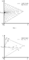
- As shown in
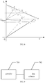
FIG 1 , the HPMINDE algorithm commonly used at this stage, for the hypo-color field problem, the colors outside the color gamut are all cut to the boundary of the target color gamut, the colors within the color gamut is directly outputted as itis. As shown inFIG. 2 , the color within the color gamut is outputted as it is, to ensure the accurate presenting of the color within the color gamut; the point outside the color gamut is mapped in the point direction toward the luminance axis, the color outside the region is mapped in the boundary of the color gamut successively, the area of the color gamut and the mapping line exit a bigger difference, and directly leads to poor mapping uniformity. - For the color gamut mapping algorithm, especially in the process of larger color gamut mapping to the small color gamut, in common algorithm, for the color point located outside the small color gamut is mapping to some point along and toward the direction of the luminance axis, such as small area color gamut of ABHG projecting to the target area for AB, and a large area color gamut of EFJI projecting to the target area for EF, and EF is significantly shorter than AB, resulting in the problems of insufficient uniformity of the mapping, insufficient of the level of detail of the color, and so on.
- The technical problem solved by the invention is to provide a color gamut mapping algorithm, to obtain the coordinates of the mapping points by the proportion of the area, determine the mapping direction, and improve the uniformity and the level of detail of the color points on the boundary.
- In order to solve the above technical problem, the present invention provides a color gamut mapping method including the steps of:
- Determining a mapping target color gamut of an original color gamut in the same color gamut space; wherein an area of the mapping target color gamut is smaller than an area of the original color gamut;
- Obtaining a Lab value of a color point in the original color gamut, and determining a coordinate position of the color point in a corresponding tone plane of the original color gamut according to the Lab value;
- Judging whether the color point located outside a mapping target area or not according to the coordinate position;
- If the color point located outside the mapping target area, determining an intersection of a horizontal line where the color point located and a boundary of the original color gamut, and a boundary of the mapping target color gamut;
- Determining a mapping point of the color point on the boundary of the map target color gamut by a ratio of an area of a pattern formed by the intersection, and an intersection of the original color gamut and a coordinate axis, and a difference between the area of the original color gamut and the area of the mapping target color gamut;
- Determining a correspondence point located on the coordinate axis of the pattern formed by the intersection and the intersection of the original color gamut and the coordinate axis according to the ratio, determining an intersection of the connection between the correspondence point and the color point and a boundary of the target mapping target color gamut as a mapping point of the color point on the boundary of the mapping target color gamut;
- Obtaining a mapping point distribution of each line segment of the boundary of the mapping target color gamut, according to the mapping point on the boundary of the map target color gamut;
- Adjusting a color point mapping direction outside the mapping target area, according to the mapping point distribution of each line segment of the boundary of the mapping target color gamut, making a number of the mapping points on an unit length of the boundary of the mapping target color gamut the same; and
- Re-converting and outputting the Lab value of the color point with the adjusted mapping direction to a RGB gray scale value.
- In order to solve the above technical problem, the present invention provides another color gamut mapping method including the steps of:
- Determining a mapping target color gamut of an original color gamut in the same color gamut space; wherein an area of the mapping target color gamut is smaller than an area of the original color gamut;
- Obtaining a Lab value of a color point in the original color gamut, and determining a coordinate position of the color point in a corresponding tone plane of the original color gamut according to the Lab value;
- Judging whether the color point located outside a mapping target area or not according to the coordinate position;
- If the color point located outside the mapping target area, determining an intersection of a horizontal line where the color point located and a boundary of the original color gamut, and a boundary of the mapping target color gamut; and
- Determining a mapping point of the color point on the boundary of the map target color gamut by a ratio of an area of a pattern formed by the intersection, and an intersection of the original color gamut and a coordinate axis, and a difference between the area of the original color gamut and the area of the mapping target color gamut.
- In order to solve the above technical problem, the present invention provides a color gamut mapping device, the color gamut mapping device includes a controller and a data collector electrically connected to each other;
The controller for determining a mapping target color gamut of an original color gamut in the same color gamut space, wherein, an area of the mapping target color gamut is smaller than an area of the original color gamut;
The data collector for obtaining a Lab value of the color point in the original color gamut, and determining a coordinate position of the color point in a corresponding tone plane of the original color gamut according to the Lab value; and
The controller further for judging whether the color point located outside a mapping target area or not according to the coordinate position; if the color point located outside the mapping target area, determining an intersection of a horizontal line where the color point located and a boundary of the original color gamut, and a boundary of the mapping target color gamut; determining a mapping point of the color point on the boundary of the map target color gamut by a ratio of an area of a pattern formed by the intersection, and an intersection of the original color gamut and a coordinate axis, and a difference between the area of the original color gamut and the area of the mapping target color gamut. - The advantages of the present invention, comparing to the conventional technology, the present application by determining the mapping target color gamut of the original color gamut in the same color gamut space; obtaining the Lab value of the color point in the original color gamut, and determining the coordinate position of the color point in the corresponding tone plane of the original color gamut according to the Lab value and judging the color point mapping target area according to the coordinate position; if the color point is located outside the mapping target area, determining the intersection of the horizontal line where the color point is located and the boundary of the original color gamut and the boundary of the mapping target color gamut; determining the mapping point of the color point on the boundary of the map target color gamut by the area formed by the intersection, and the intersection of the original color gamut and the coordinate axis and the ratio of the area between the original color gamut and the mapping target color gamut. By the above way, the uniformity of the color points on the boundary is improved, and the color detail level is improved.
- Accompanying drawings are for providing further understanding of embodiments of the disclosure. The drawings form a part of the disclosure and are for illustrating the principle of the embodiments of the disclosure along with the literal description. Apparently, the drawings in the description below are merely some embodiments of the disclosure, a person skilled in the art can obtain other drawings according to these drawings without creative efforts. In the FIG.s:
-
FIG. 1 is a schematic diagram of a cutting target color gamut boundary of a color outside the color gamut by the HPMINDE algorithm of the conventional technology; -
FIG. 2 is a schematic diagram of a mapping in the corresponding boundary of a region outside the color gamut by the HPMINDE algorithm of the conventional technology; -
FIG. 3 is a flow chart showing a color gamut mapping method of an embodiment of the present invention; -
FIG. 4 is a schematic calculation diagram of a chroma value of the color point of an embodiment of the color gamut mapping method shown inFIG. 3 ; -
FIG. 5 is a schematic diagram of a corresponding mapping pattern of an embodiment of the color gamut mapping method shown inFIG. 3 ; -
FIG. 6 is a schematic diagram of a corresponding mapping pattern of another embodiment of the color gamut mapping method shown inFIG. 3 ; and -
FIG. 7 is a schematic structural view of a color gamut mapping device of an embodiment according to the present invention. - The disclosure will be further described in detail with reference to accompanying drawings and preferred embodiments as follows.
- Referring to
FIG. 3, FIG. 3 is a flow chart showing a color gamut mapping method of an embodiment of the present invention; the color gamut mapping method of the present embodiment includes the steps of:
301: determining a mapping target color gamut of the original color gamut in the same color gamut space; wherein the area of the mapping target color gamut is smaller than the area of the original color gamut. - Alternatively, the original color gamut and the mapping target color gamut include a computer graphics color gamut space, a CIE color gamut space, and a TV system color gamut space, for example the original color gamut is the sRGB color gamut, the mapping target color gamut is the Lab color gamut, in other embodiments, it can be the other two different color gamut mapping to each other, and are not limited herein.
- Specifically, the original color gamut and the mapping target color gamut confirm all the color spaces, and place the color gamut space in the same coordinate system.
- 302: obtaining the Lab value of the color point in the original color gamut, and determining the coordinate position of the color point in the corresponding tone plane of the original color gamut according to the Lab value.
- Specifically, first, the RGB gray scale value of the color point in the original color gamut is obtained, and the Lab value of the color point in the original color gamut is obtained according to the RGB gray scale value; by using the Lab value of the color point in the original color gamut, the color point in the original color gamut and the luminance axis are plotted, to obtain the chroma value and the hue of the color point in the tone plane corresponding to the original color gamut; determining the coordinate position of the color point in the tone plane corresponding to the original color gamut according to the chroma value and the hue.
- In order to clearly illustrate the above process, in a specific embodiment, as shown in
FIG. 4, FIG. 4 is a schematic calculation diagram of a chroma value of the color point of an embodiment of the color gamut mapping method shown inFIG. 3 ; inFIG. 4 , the horizontal axis is the chroma value, the vertical axis is the luminance. In this coordinate system, by using the Lab value of the color point in the original color gamut, that is the luminance value L, the color value of red/green a and the color value of yellow/blue b, using any point P (C*, L*) and the luminance axis for the plane, the original color gamut three-dimensional space is transferred into a two-dimensional plane, by the color value of red/green a and the color value of yellow/blue b, to determine the hue H * and the chroma value (C*, L*) of the current P point, specifically, as the following equations 1 to 3.


- Wherein, in order to obtain the Lab value of the color point in the original color gamut, after obtaining the RGB gray scale value of the color point in the original color gamut, the RGB gray scale value of the color point in the original color gamut is converted into the RGB optical value of the color point in the original color gamut by the conversion equation; and converting the RGB optical value of the color point in the original color gamut into the three stimulus value of the color point in the original color gamut; and finally converting the three stimulus values of the color points in the original color gamut into the Lab value of the color points in the original color gamut.
- Preferably, the RGB gray scale value of the color point in the original color gamut is converted into the optical value of the color point in the original color gamut by Gamma2.2.
- Wherein, Gamma2.2 is a special tone curve, when the Gamma value is equal to 1, the curve is a straight line and 45 ° with the coordinate axis, this time means that the input and output density is the same, the Gamma2.2 higher than 1 will make the output brightened.
- Preferably, the RGB optical values of the color points in the original color gamut are converted to the three stimulus values of the color points in the original color gamut by the conversion matrix.
- Under normal circumstances, the RGB gray scale value cannot be directly converted to the Lab value, it need to be first converted to the XYZ three stimulus value and then converted to the Lab value (that is: RGB gray scale value-XYZ tristimulus values-Lab value), in an alternatively embodiment, the RGB gray scale value is first converted to the XYZ tristimulus values.
- Specifically, assuming that r, g, b for the three channels of pixels, the range of values are [0,255], the conversion formula is as follows:


- Where the conversion matrix is as follows:

- Equivalent to the following formula:


- After obtaining the stimulus value of red primary color X, the stimulus value of green primary color Y, and the stimulus value of blue primary color Z, are converting into the Lab values.


- Wherein X is the stimulus value of red primary color, Y is the stimulus value of green primary color, Z is the stimulus value of blue primary color, default values are adapted for Xn, Yn, Zn as 95.047, 100.0, 108.883, respectively, f(t) is for the correction function, t is the correction parameter, L* is for the luminance value, a* is for the color value of red/green, b* is for the color value of yellow/blue.
- 303: judging whether the color point is located outside the mapping target area or not according to the coordinate position.
- In an alternative embodiment, the coordinate position is compared with the boundary function of the mapping target color gamut, to judge whether the color point is located outside the mapping target area or not.
- Specifically, after obtaining the Lab value of the color point in the original color gamut, the luminance value L, the color value of red/green a and the color value of yellow/blue b are obtained, the hue H of the two-dimensional plane and the chroma value (C, L) of the two-dimensional plane is obtained according to the above formulas (1∼3), putting the resulting values of the hue and the chroma value into the boundary function of the mapping target color gamut to determine the color point position relationship.
- 304: If the color point is located outside the mapping target area, determine the intersection of the horizontal line where the color point is located and the boundary of the original color gamut, and the boundary of the mapping target color gamut.
- Specifically, as shown in
FIG. 5, FIG. 5 is a schematic diagram of a corresponding mapping pattern of an embodiment of the color gamut mapping method shown inFIG. 3 ; the point P in the FIG. is used as the horizontal line h, the horizontal line h intersects the boundary of the original color gamut at point N, and intersects the boundary of the mapping target color gamut at point M. - Wherein, the Lab value of the color point is directly converted into an RGB gray scale value and outputted, if the color point is located in the mapping target area.
- 305: determining the mapping point of the color point on the boundary of the map target color gamut by the area formed by the intersection, and the intersection of the original color gamut and the coordinate axis and the ratio of the area between the original color gamut and the mapping target color gamut.
- In an alternative embodiment, the pattern formed by the intersection and the intersection of the original color gamut and the coordinate axis located in the correspondence point of the coordinate axis is determined according to the ratio; the intersection of the connection between the correspondence point and the color point and the boundary of the target mapping target color gamut is determined as the mapping point of the color point on the boundary of the mapping target color gamut. The ratio of the difference between the correspondence point and the vertical coordinate distance of the mapping target color gamut and the vertical coordinates of the mapping target color gamut is equal to the above ratio.
- Specifically, as shown in
FIG. 5 , it is assumed that the difference area between the original color gamut and the mapping target color gamut is S, and S=SΔ(LxDO) -SΔ(LxTO) is obtained; having a horizontal line h passes a color point P outside the target color gamut, the horizontal line intersects the two boundaries at M, N points, the area forms by the MN line and the boundaries of the color gamut is A, that is A=SΔ(LxMN); having a line passes p line, the line intersects the vertical axis at the point LT, and intersects the mapping target color gamut boundary at point p', to let A/S=LxLT/LxO, get the LT coordinate value combined with the color point P coordinate value to confirm the line segment LTP function, substituting the above results into the mapping target gamut boundary function results in the mapping point p'. - Further, obtaining a mapping point distribution of each line segment of the boundary of the mapping target color gamut, according to the mapping point on the boundary of the map target color gamut; and adjusting the color point mapping direction outside the mapping target area, according to the mapping point distribution of each line segment of the boundary of the mapping target color gamut, making the number of mapping points in the unit length of the boundary of the mapping target color gamut is the same, under normal circumstances, it is acceptable to ensure that the number of mapping points in the unit length of the boundary of the mapping target color gamut is within a up and down range of 10%, and then re-converting the Lab value of the color point with the adjusted mapping direction to the RGB gray scale value and outputting.
- Specifically, as shown in
FIG. 6, FIG. 6 is a schematic diagram of a corresponding mapping pattern of another embodiment of the color gamut mapping method shown inFIG. 3 . The distribution of the mapping points of the respective color points in the original color gamut on the boundary of the mapping target color gamut is obtained by the above-mentioned method, and the uniformity of the mapping is represented by the number of mapping points per unit length, i.e., β= area S/length L. If the number of mapping points of the mapping line segment is small, as the color area corresponding to the line segment AB, the original area ABQP is increased to the area ABJI, that is, adjusting the mapping direction of the color point, and the connecting direction of the color points within the area ABJI and the corresponding mapping point are fixed in the line segment AB; If the number of mapping points of the mapping line segment is large, as the color area corresponding to the line segment EF, the original mapping corresponding line segment EF is increased to line segment EK, that is adjusting the connecting direction of the color points within the area EFHG and the corresponding mapping point, so that the direction is fixed within the line segment EK, that is, the original area EFHG is performed mapping to the line segment EK direction. The Lab value of the color point after adjusting the mapping direction is converted into the tristimulus value, the specific formulas are as followed 9-10, and then the tristimulus value is converted into the RGB optical value through the conversion matrix, and finally converted into RGB gray scale value by Gamma2.2 Value and outputting.

- Wherein, Xn, Yn, Zn using the default values are 95.047, 100.0, 108.883, respectively, L is for the luminance value, a is for the color value of red/green, b is for the color value of yellow/blue, t is for the correction parameters, f(t) is for the correction function.
- In a specific embodiment, in inputting the sRGB color gamut space, the RGB gray scale values is converted to the Lab value by the sequentially calculations of the RGB gray scale value of the respective color points in the sRGB color gamut by the gamma2.2 function and the TM conversion matrix and the conversion equation, the area of each color point located is determined by the Lab value, the mapping direction of each of the color points outside the mapping target area is changed by the simulation calculations (specifically, the above-described embodiments), the Lab value of the color point after adjusting the mapping direction is re-converted to the RGB gray scale value and outputting.
- Comparing to the conventional technology, in the present embodiment, by determining the mapping target color gamut of the original color gamut in the same color gamut space; obtaining the Lab value of the color point in the original color gamut, and determining the coordinate position of the color point in the corresponding tone plane of the original color gamut according to the Lab value and judging the color point mapping target area according to the coordinate position; if the color point is located outside the mapping target area, determining the intersection of the horizontal line where the color point is located and the boundary of the original color gamut and the boundary of the mapping target color gamut; determining the mapping point of the color point on the boundary of the map target color gamut by the area formed by the intersection, and the intersection of the original color gamut and the coordinate axis and the ratio of the area between the original color gamut and the mapping target color gamut. By the above way, the uniformity of the color points on the boundary is improved, and the color detail level is improved.
- The present invention also provides a color gamut mapping device, referring to
FIG. 7, Fig. 7 is a schematic structural view of a color gamut mapping device of an embodiment according to the present invention, including acontroller 701 and adata collector 702 electrically connected to each other; thecontroller 701 is for determining the mapping target color gamut of the original color gamut in the same color gamut space, wherein, the area of the mapping target color gamut is smaller than the area of the original color gamut; thedata collector 702 is for obtaining the Lab value of the color point in the original color gamut, and determining the coordinate position of the color point in the corresponding tone plane of the original color gamut according to the Lab value. Thecontroller 702 is further for determining whether the color point is located outside the mapping target area or not according to the coordinate position; if the color point is located outside the mapping target area, determine the intersection of the horizontal line where the color point is located and the boundary of the original color gamut, and the boundary of the mapping target color gamut; determining the mapping point of the color point on the boundary of the map target color gamut by the area formed by the intersection, and the intersection of the original color gamut and the coordinate axis and the ratio of the area between the original color gamut and the mapping target color gamut. - The detail executing process can be referring to
FIGS. 3 to 6 and the related descriptions of any of the embodiments, and will not be described here. - Comparing to the conventional technology, in the present embodiment, by determining the mapping target color gamut of the original color gamut in the same color gamut space; obtaining the Lab value of the color point in the original color gamut, and determining the coordinate position of the color point in the corresponding tone plane of the original color gamut according to the Lab value and judging the color point mapping target area according to the coordinate position; if the color point is located outside the mapping target area, determining the intersection of the horizontal line where the color point is located and the boundary of the original color gamut and the boundary of the mapping target color gamut; determining the mapping point of the color point on the boundary of the map target color gamut by the area formed by the intersection, and the intersection of the original color gamut and the coordinate axis and the ratio of the area between the original color gamut and the mapping target color gamut. By the above way, the uniformity of the color points on the boundary is improved, and the color detail level is improved.
- Further, the present embodiment further simplifies the calculation process of the color gamut mapping process by the color gamut mapping device, and all the colors outside the color gamut are shift to the target color gamut boundary by the color gamut mapping device, and the mapping directions of the respective color point is optimized, to improve the uniformity of the color points mapping on the boundary and the level of detail and other issues.
- The foregoing contents are detailed description of the disclosure in conjunction with specific preferred embodiments and concrete embodiments of the disclosure are not limited to these descriptions. For the person skilled in the art of the disclosure, without departing from the concept of the disclosure, simple deductions or substitutions can be made and should be included in the protection scope of the application.
Claims (20)
- A color gamut mapping method, comprising the steps of:determining a mapping target color gamut of an original color gamut in the same color gamut space; wherein an area of the mapping target color gamut is smaller than an area of the original color gamut;obtaining a Lab value of a color point in the original color gamut, and determining a coordinate position of the color point in a corresponding tone plane of the original color gamut according to the Lab value;judging whether the color point located outside a mapping target area or not according to the coordinate position;if the color point located outside the mapping target area, determining an intersection of a horizontal line where the color point located and a boundary of the original color gamut, and a boundary of the mapping target color gamut;determining a mapping point of the color point on the boundary of the map target color gamut by a ratio of an area of a pattern formed by the intersection, and an intersection of the original color gamut and a coordinate axis, and a difference between the area of the original color gamut and the area of the mapping target color gamut;determining a correspondence point located on the coordinate axis of the pattern formed by the intersection and the intersection of the original color gamut and the coordinate axis according to the ratio, determining an intersection of the connection between the correspondence point and the color point and a boundary of the target mapping target color gamut as a mapping point of the color point on the boundary of the mapping target color gamut;obtaining a mapping point distribution of each line segment of the boundary of the mapping target color gamut, according to the mapping point on the boundary of the map target color gamut;adjusting a color point mapping direction outside the mapping target area, according to the mapping point distribution of each line segment of the boundary of the mapping target color gamut, making a number of the mapping points on an unit length of the boundary of the mapping target color gamut the same; andre-converting and outputting the Lab value of the color point with the adjusted mapping direction to a RGB gray scale value.
- The color gamut mapping method according to claim 1, wherein a ratio of a difference between the correspondence point and a vertical coordinate distance of the mapping target color gamut, and the vertical coordinates of the mapping target color gamut is equal to the ratio.
- The color gamut mapping method according to claim 1, wherein the step of obtaining the Lab value of the color point in the original color gamut, and determining the coordinate position of the color point in the corresponding tone plane of the original color gamut according to the Lab value specifically comprises:obtaining a RGB gray scale value of the color point in the original color gamut, obtaining the Lab value of the color point in the original color gamut according to the RGB gray scale value;by using the Lab value of the color point in the original color gamut, plotting a plane by the color point in the original color gamut and a luminance axis, obtaining a chroma value and a hue of the color point in the tone plane corresponding to the original color gamut; anddetermining the coordinate position of the color point in the tone plane corresponding to the original color gamut according to the chroma value and the hue.
- The color gamut mapping method according to claim 3, wherein the step of obtaining the RGB gray scale value of the color point in the original color gamut, obtaining the Lab value of the color point in the original color gamut according to the RGB gray scale value specifically comprises:obtaining the RGB gray scale value of the color point in the original color gamut, converting the RGB gray scale value of the color point in the original color gamut into an RGB optical value of the color point in the original color gamut;converting the RGB optical value of the color point in the original color gamut into a tristimulus value of the color point in the original color gamut; andconverting the three stimulus values of the color points in the original color gamut into the Lab values of the color points in the original color gamut.
- The color gamut mapping method according to claim 4, wherein the RGB optical value of the color point in the original color gamut is converted into the tristimulus value of the color point within the original color gamut by a conversion matrix.
- The color gamut mapping method according to claim 1, wherein the step of judging whether the color point located outside the mapping target area or not according to the coordinate position specifically comprises:
comparing the coordinate position with a boundary function of the mapping target color gamut to determine whether the color point is located outside the mapping target area or not. - A color gamut mapping method, comprising the steps of:determining a mapping target color gamut of an original color gamut in the same color gamut space; wherein an area of the mapping target color gamut is smaller than an area of the original color gamut;obtaining a Lab value of a color point in the original color gamut, and determining a coordinate position of the color point in a corresponding tone plane of the original color gamut according to the Lab value;judging whether the color point located outside a mapping target area or not according to the coordinate position;if the color point located outside the mapping target area, determining an intersection of a horizontal line where the color point located and a boundary of the original color gamut, and a boundary of the mapping target color gamut; anddetermining a mapping point of the color point on the boundary of the map target color gamut by a ratio of an area of a pattern formed by the intersection, and an intersection of the original color gamut and a coordinate axis, and a difference between the area of the original color gamut and the area of the mapping target color gamut.
- The color gamut mapping method according to claim 7, wherein the step of determining the mapping point of the color point on the boundary of the map target color gamut by the ratio of the area of the pattern formed by the intersection, and the intersection of the original color gamut and the coordinate axis, and the difference between the area of the original color gamut and the area of the mapping target color gamut specifically comprises:determining a correspondence point located on the coordinate axis of the pattern formed by the intersection and the intersection of the original color gamut and the coordinate axis according to the ratio; anddetermining an intersection of the connection between the correspondence point and the color point and a boundary of the target mapping target color gamut as a mapping point of the color point on the boundary of the mapping target color gamut.
- The color gamut mapping method according to claim 8, wherein a ratio of a difference between the correspondence point and a vertical coordinate distance of the mapping target color gamut, and the vertical coordinates of the mapping target color gamut is equal to the ratio.
- The color gamut mapping method according to claim 7, wherein the step of obtaining the Lab value of the color point in the original color gamut, and determining the coordinate position of the color point in the corresponding tone plane of the original color gamut according to the Lab value specifically comprises:obtaining a RGB gray scale value of the color point in the original color gamut, obtaining the Lab value of the color point in the original color gamut according to the RGB gray scale value;by using the Lab value of the color point in the original color gamut, plotting a plane by the color point in the original color gamut and a luminance axis, obtaining a chroma value and a hue of the color point in the tone plane corresponding to the original color gamut; anddetermining the coordinate position of the color point in the tone plane corresponding to the original color gamut according to the chroma value and the hue.
- The color gamut mapping method according to claim 10, wherein the step of obtaining the RGB gray scale value of the color point in the original color gamut, obtaining the Lab value of the color point in the original color gamut according to the RGB gray scale value specifically comprises:obtaining the RGB gray scale value of the color point in the original color gamut, converting the RGB gray scale value of the color point in the original color gamut into an RGB optical value of the color point in the original color gamut;converting the RGB optical value of the color point in the original color gamut into a tristimulus value of the color point in the original color gamut; andconverting the three stimulus values of the color points in the original color gamut into the Lab values of the color points in the original color gamut.
- The color gamut mapping method according to claim 11, wherein the RGB optical value of the color point in the original color gamut is converted into the tristimulus value of the color point within the original color gamut by a conversion matrix.
- The color gamut mapping method according to claim 7, wherein the step of judging whether the color point located outside the mapping target area or not according to the coordinate position specifically comprises:
comparing the coordinate position with a boundary function of the mapping target color gamut to determine whether the color point is located outside the mapping target area or not. - The color gamut mapping method according to claim 7, wherein after the step of determining the mapping point of the color point on the boundary of the map target color gamut by the ratio of the area of the pattern formed by the intersection, and the intersection of the original color gamut and the coordinate axis, and the difference between the area of the original color gamut and the area of the mapping target color gamut further comprises:obtaining a mapping point distribution of each line segment of the boundary of the mapping target color gamut, according to the mapping point on the boundary of the map target color gamut;adjusting a color point mapping direction outside the mapping target area, according to the mapping point distribution of each line segment of the boundary of the mapping target color gamut, making a number of the mapping points on an unit length of the boundary of the mapping target color gamut the same; andre-converting and outputting the Lab value of the color point with the adjusted mapping direction to a RGB gray scale value.
- The color gamut mapping method according to claim 7, wherein the step of if the color point located outside the mapping target area, determining an intersection of a horizontal line where the color point located and a boundary of the original color gamut, and a boundary of the mapping target color gamut further comprises:
directly converting and outputting the Lab value of the color point into the RGB gray scale value, if the color point is located within the mapping target area. - A color gamut mapping device, comprising:a controller and a data collector electrically connected to each other;the controller for determining a mapping target color gamut of an original color gamut in the same color gamut space, wherein, an area of the mapping target color gamut is smaller than an area of the original color gamut;the data collector for obtaining a Lab value of the color point in the original color gamut, and determining a coordinate position of the color point in a corresponding tone plane of the original color gamut according to the Lab value; andthe controller further for judging whether the color point located outside a mapping target area or not according to the coordinate position; if the color point located outside the mapping target area, determining an intersection of a horizontal line where the color point located and a boundary of the original color gamut, and a boundary of the mapping target color gamut; determining a mapping point of the color point on the boundary of the map target color gamut by a ratio of an area of a pattern formed by the intersection, and an intersection of the original color gamut and a coordinate axis, and a difference between the area of the original color gamut and the area of the mapping target color gamut.
- The color gamut mapping device according to claim 16, wherein the controller is specifically for determining a correspondence point located on the coordinate axis of the pattern formed by the intersection and the intersection of the original color gamut and the coordinate axis according to the ratio; and determining an intersection of the connection between the correspondence point and the color point and a boundary of the target mapping target color gamut as a mapping point of the color point on the boundary of the mapping target color gamut.
- The color gamut mapping device according to claim 16, wherein the data collector is specifically for obtaining a RGB gray scale value of the color point in the original color gamut, obtaining the Lab value of the color point in the original color gamut according to the RGB gray scale value; by using the Lab value of the color point in the original color gamut, plotting a plane by the color point in the original color gamut and a luminance axis, obtaining a chroma value and a hue of the color point in the tone plane corresponding to the original color gamut; and determining the coordinate position of the color point in the tone plane corresponding to the original color gamut according to the chroma value and the hue.
- The color gamut mapping device according to claim 18, wherein the data collector is specifically for obtaining the RGB gray scale value of the color point in the original color gamut, converting the RGB gray scale value of the color point in the original color gamut into an RGB optical value of the color point in the original color gamut; converting the RGB optical value of the color point in the original color gamut into a tristimulus value of the color point in the original color gamut; and converting the three stimulus values of the color points in the original color gamut into the Lab values of the color points in the original color gamut.
- The color gamut mapping device according to claim 16, wherein the controller is specifically for obtaining a mapping point distribution of each line segment of the boundary of the mapping target color gamut, according to the mapping point on the boundary of the map target color gamut; adjusting a color point mapping direction outside the mapping target area, according to the mapping point distribution of each line segment of the boundary of the mapping target color gamut, making a number of the mapping points on an unit length of the boundary of the mapping target color gamut the same; and re-converting and outputting the Lab value of the color point with the adjusted mapping direction to a RGB gray scale value.
Applications Claiming Priority (2)
| Application Number | Priority Date | Filing Date | Title |
|---|---|---|---|
| CN201710863261.XA CN107680141B (en) | 2017-09-21 | 2017-09-21 | A kind of method of color gamut mapping of color and its gamut mapping apparatus |
| PCT/CN2017/107124 WO2019056445A1 (en) | 2017-09-21 | 2017-10-20 | Color gamut mapping method and device |
Publications (3)
| Publication Number | Publication Date |
|---|---|
| EP3686847A1 true EP3686847A1 (en) | 2020-07-29 |
| EP3686847A4 EP3686847A4 (en) | 2021-05-26 |
| EP3686847B1 EP3686847B1 (en) | 2024-12-04 |
Family
ID=61137855
Family Applications (1)
| Application Number | Title | Priority Date | Filing Date |
|---|---|---|---|
| EP17925837.1A Active EP3686847B1 (en) | 2017-09-21 | 2017-10-20 | Color gamut mapping method and device |
Country Status (6)
| Country | Link |
|---|---|
| US (1) | US10728425B2 (en) |
| EP (1) | EP3686847B1 (en) |
| JP (1) | JP6793281B2 (en) |
| KR (1) | KR102351725B1 (en) |
| CN (1) | CN107680141B (en) |
| WO (1) | WO2019056445A1 (en) |
Families Citing this family (8)
| Publication number | Priority date | Publication date | Assignee | Title |
|---|---|---|---|---|
| CN110278422B (en) * | 2018-03-16 | 2022-01-11 | 深圳光峰科技股份有限公司 | Display device |
| CN110278423B (en) * | 2018-03-16 | 2021-10-12 | 深圳光峰科技股份有限公司 | Display device |
| CN109119046B (en) * | 2018-09-10 | 2020-06-05 | 深圳市华星光电技术有限公司 | Adjusting system and adjusting method for gray scale brightness and memory |
| CN110087052B (en) * | 2019-05-06 | 2021-07-23 | Tcl华星光电技术有限公司 | Color gamut mapping method, device and storage medium |
| CN111341283B (en) * | 2020-04-20 | 2022-04-22 | 深圳Tcl数字技术有限公司 | Color gamut mapping method, color gamut mapping assembly and display device |
| CN115909984B (en) * | 2022-11-02 | 2024-04-23 | 佛山市青松科技股份有限公司 | Color mapping method, system, computer device and computer readable storage medium |
| CN119963448B (en) * | 2025-01-09 | 2026-03-31 | 重庆赛力斯凤凰智创科技有限公司 | Image processing methods, apparatus, electronic devices and storage media |
| CN119846556B (en) * | 2025-03-17 | 2025-08-12 | 中国人民解放军海军大连舰艇学院 | Method for calculating time difference positioning measurement error |
Family Cites Families (14)
| Publication number | Priority date | Publication date | Assignee | Title |
|---|---|---|---|---|
| KR100800736B1 (en) | 2003-12-30 | 2008-02-01 | 삼성전자주식회사 | Color matching method between devices with LCD and CRT display |
| KR20060068595A (en) * | 2004-12-16 | 2006-06-21 | 주식회사 하이닉스반도체 | Semiconductor device manufacturing method |
| KR100605164B1 (en) * | 2005-01-28 | 2006-07-28 | 삼성전자주식회사 | Color gamut mapping device and method |
| KR101303874B1 (en) * | 2006-02-10 | 2013-09-04 | 삼성전자주식회사 | Apparatus and method for gamut mapping |
| JP4845127B2 (en) * | 2007-03-07 | 2011-12-28 | 株式会社リコー | Image processing device |
| JP2008271131A (en) * | 2007-04-19 | 2008-11-06 | Sharp Corp | Image processing method, image processing apparatus, and image forming apparatus |
| KR101319335B1 (en) * | 2007-06-22 | 2013-10-16 | 엘지디스플레이 주식회사 | Color gamut mapping method and liquid crystal display device using the same |
| US8355572B2 (en) * | 2009-03-12 | 2013-01-15 | Xerox Corporation | Mapping an out of gamut RGB color to a gamut surface |
| CN102209179B (en) * | 2011-05-31 | 2012-10-31 | 武汉大学 | An Adaptive Color Gamut Matching Method Based on Image Color Gamut |
| US9866730B2 (en) * | 2013-05-31 | 2018-01-09 | Intel Corporation | Semi-fixed-hue gamut compression |
| JP2015032925A (en) * | 2013-07-31 | 2015-02-16 | ブラザー工業株式会社 | Processing device and computer program |
| GB2526875B (en) * | 2014-06-06 | 2017-03-29 | Imagination Tech Ltd | Gamut mapping |
| CN104112081B (en) * | 2014-07-31 | 2017-02-08 | 上海理工大学 | Color gamut border description method |
| WO2016031911A1 (en) * | 2014-08-29 | 2016-03-03 | シャープ株式会社 | Control information generating device, receiving device, video signal transmitting system and control program |
-
2017
- 2017-09-21 CN CN201710863261.XA patent/CN107680141B/en active Active
- 2017-10-20 EP EP17925837.1A patent/EP3686847B1/en active Active
- 2017-10-20 JP JP2020512009A patent/JP6793281B2/en active Active
- 2017-10-20 WO PCT/CN2017/107124 patent/WO2019056445A1/en not_active Ceased
- 2017-10-20 KR KR1020207011316A patent/KR102351725B1/en active Active
- 2017-10-20 US US15/735,866 patent/US10728425B2/en active Active
Also Published As
| Publication number | Publication date |
|---|---|
| EP3686847A4 (en) | 2021-05-26 |
| KR102351725B1 (en) | 2022-01-13 |
| CN107680141B (en) | 2018-11-23 |
| JP2020532236A (en) | 2020-11-05 |
| US10728425B2 (en) | 2020-07-28 |
| US20200036867A1 (en) | 2020-01-30 |
| CN107680141A (en) | 2018-02-09 |
| WO2019056445A1 (en) | 2019-03-28 |
| EP3686847B1 (en) | 2024-12-04 |
| JP6793281B2 (en) | 2020-12-02 |
| KR20200054299A (en) | 2020-05-19 |
Similar Documents
| Publication | Publication Date | Title |
|---|---|---|
| EP3686847B1 (en) | Color gamut mapping method and device | |
| US10791249B2 (en) | Color gamut mapping method and color gamut mapping apparatus | |
| US6262817B1 (en) | System and method for adjusting a color image | |
| US10896635B2 (en) | Primary color conversion method and converter thereof, display control method, and display device | |
| CN100372357C (en) | Color gamut mapping device and method using vector stretching | |
| US5664072A (en) | Color conversion device | |
| CN108810507B (en) | A kind of gamut conversion method and gamut converter, display device | |
| US7215343B2 (en) | Color correction using a device-dependent display profile | |
| KR102601853B1 (en) | Display device and image processing method thereof | |
| EP3163566A1 (en) | Rgb signal to rgbw signal image conversion method and apparatus | |
| CN104869378A (en) | Color gamut matching method based on source image color gamut | |
| CN105070270A (en) | RGBW panel subpixel compensation method and device | |
| KR101967416B1 (en) | Technique for color profiling of a display device | |
| US12620134B2 (en) | Generating color correction model including color space conversion, through an interpolation algorithm according to color data of reference sampling points | |
| CN102075665B (en) | Color conversion table creating apparatus and color conversion table creating method | |
| EP1931128B1 (en) | Apparatus and method of reproducing preferred color | |
| JP2009065532A (en) | Image processing apparatus, image processing method, and computer-readable storage medium storing image processing program | |
| CN120636343A (en) | Processing method and device for splicing display screen and splicing display device | |
| US20070230780A1 (en) | Hue correction system and method thereof | |
| US20050276473A1 (en) | Apparatus and method of detecting color gamut in color device and calculating color space inverse transform function | |
| US10360873B2 (en) | Method and system for generating images on display | |
| CN110047415A (en) | Method of color gamut mapping of color, electronic equipment and storage medium | |
| JP2010148065A (en) | Image processing unit | |
| JP2023117585A (en) | Method and device for generating profile | |
| JP2000341548A (en) | Color gamut compression apparatus and color gamut compression method |
Legal Events
| Date | Code | Title | Description |
|---|---|---|---|
| STAA | Information on the status of an ep patent application or granted ep patent |
Free format text: STATUS: THE INTERNATIONAL PUBLICATION HAS BEEN MADE |
|
| PUAI | Public reference made under article 153(3) epc to a published international application that has entered the european phase |
Free format text: ORIGINAL CODE: 0009012 |
|
| STAA | Information on the status of an ep patent application or granted ep patent |
Free format text: STATUS: REQUEST FOR EXAMINATION WAS MADE |
|
| 17P | Request for examination filed |
Effective date: 20200325 |
|
| AK | Designated contracting states |
Kind code of ref document: A1 Designated state(s): AL AT BE BG CH CY CZ DE DK EE ES FI FR GB GR HR HU IE IS IT LI LT LU LV MC MK MT NL NO PL PT RO RS SE SI SK SM TR |
|
| AX | Request for extension of the european patent |
Extension state: BA ME |
|
| DAV | Request for validation of the european patent (deleted) | ||
| DAX | Request for extension of the european patent (deleted) | ||
| A4 | Supplementary search report drawn up and despatched |
Effective date: 20210428 |
|
| RIC1 | Information provided on ipc code assigned before grant |
Ipc: G06T 7/90 20170101AFI20210421BHEP Ipc: G06T 5/00 20060101ALI20210421BHEP |
|
| GRAJ | Information related to disapproval of communication of intention to grant by the applicant or resumption of examination proceedings by the epo deleted |
Free format text: ORIGINAL CODE: EPIDOSDIGR1 |
|
| GRAP | Despatch of communication of intention to grant a patent |
Free format text: ORIGINAL CODE: EPIDOSNIGR1 |
|
| INTC | Intention to grant announced (deleted) | ||
| GRAP | Despatch of communication of intention to grant a patent |
Free format text: ORIGINAL CODE: EPIDOSNIGR1 |
|
| STAA | Information on the status of an ep patent application or granted ep patent |
Free format text: STATUS: GRANT OF PATENT IS INTENDED |
|
| INTG | Intention to grant announced |
Effective date: 20240508 |
|
| P01 | Opt-out of the competence of the unified patent court (upc) registered |
Free format text: CASE NUMBER: APP_34982/2024 Effective date: 20240611 |
|
| GRAJ | Information related to disapproval of communication of intention to grant by the applicant or resumption of examination proceedings by the epo deleted |
Free format text: ORIGINAL CODE: EPIDOSDIGR1 |
|
| STAA | Information on the status of an ep patent application or granted ep patent |
Free format text: STATUS: REQUEST FOR EXAMINATION WAS MADE |
|
| INTC | Intention to grant announced (deleted) | ||
| GRAP | Despatch of communication of intention to grant a patent |
Free format text: ORIGINAL CODE: EPIDOSNIGR1 |
|
| STAA | Information on the status of an ep patent application or granted ep patent |
Free format text: STATUS: GRANT OF PATENT IS INTENDED |
|
| GRAS | Grant fee paid |
Free format text: ORIGINAL CODE: EPIDOSNIGR3 |
|
| GRAA | (expected) grant |
Free format text: ORIGINAL CODE: 0009210 |
|
| STAA | Information on the status of an ep patent application or granted ep patent |
Free format text: STATUS: THE PATENT HAS BEEN GRANTED |
|
| INTG | Intention to grant announced |
Effective date: 20241004 |
|
| AK | Designated contracting states |
Kind code of ref document: B1 Designated state(s): AL AT BE BG CH CY CZ DE DK EE ES FI FR GB GR HR HU IE IS IT LI LT LU LV MC MK MT NL NO PL PT RO RS SE SI SK SM TR |
|
| REG | Reference to a national code |
Ref country code: GB Ref legal event code: FG4D |
|
| REG | Reference to a national code |
Ref country code: CH Ref legal event code: EP |
|
| REG | Reference to a national code |
Ref country code: DE Ref legal event code: R096 Ref document number: 602017086634 Country of ref document: DE |
|
| REG | Reference to a national code |
Ref country code: IE Ref legal event code: FG4D |
|
| REG | Reference to a national code |
Ref country code: LT Ref legal event code: MG9D |
|
| REG | Reference to a national code |
Ref country code: NL Ref legal event code: MP Effective date: 20241204 |
|
| PG25 | Lapsed in a contracting state [announced via postgrant information from national office to epo] |
Ref country code: HR Free format text: LAPSE BECAUSE OF FAILURE TO SUBMIT A TRANSLATION OF THE DESCRIPTION OR TO PAY THE FEE WITHIN THE PRESCRIBED TIME-LIMIT Effective date: 20241204 |
|
| PG25 | Lapsed in a contracting state [announced via postgrant information from national office to epo] |
Ref country code: FI Free format text: LAPSE BECAUSE OF FAILURE TO SUBMIT A TRANSLATION OF THE DESCRIPTION OR TO PAY THE FEE WITHIN THE PRESCRIBED TIME-LIMIT Effective date: 20241204 |
|
| PG25 | Lapsed in a contracting state [announced via postgrant information from national office to epo] |
Ref country code: BG Free format text: LAPSE BECAUSE OF FAILURE TO SUBMIT A TRANSLATION OF THE DESCRIPTION OR TO PAY THE FEE WITHIN THE PRESCRIBED TIME-LIMIT Effective date: 20241204 |
|
| PG25 | Lapsed in a contracting state [announced via postgrant information from national office to epo] |
Ref country code: ES Free format text: LAPSE BECAUSE OF FAILURE TO SUBMIT A TRANSLATION OF THE DESCRIPTION OR TO PAY THE FEE WITHIN THE PRESCRIBED TIME-LIMIT Effective date: 20241204 |
|
| PG25 | Lapsed in a contracting state [announced via postgrant information from national office to epo] |
Ref country code: NO Free format text: LAPSE BECAUSE OF FAILURE TO SUBMIT A TRANSLATION OF THE DESCRIPTION OR TO PAY THE FEE WITHIN THE PRESCRIBED TIME-LIMIT Effective date: 20250304 |
|
| PG25 | Lapsed in a contracting state [announced via postgrant information from national office to epo] |
Ref country code: LV Free format text: LAPSE BECAUSE OF FAILURE TO SUBMIT A TRANSLATION OF THE DESCRIPTION OR TO PAY THE FEE WITHIN THE PRESCRIBED TIME-LIMIT Effective date: 20241204 Ref country code: GR Free format text: LAPSE BECAUSE OF FAILURE TO SUBMIT A TRANSLATION OF THE DESCRIPTION OR TO PAY THE FEE WITHIN THE PRESCRIBED TIME-LIMIT Effective date: 20250305 |
|
| PG25 | Lapsed in a contracting state [announced via postgrant information from national office to epo] |
Ref country code: RS Free format text: LAPSE BECAUSE OF FAILURE TO SUBMIT A TRANSLATION OF THE DESCRIPTION OR TO PAY THE FEE WITHIN THE PRESCRIBED TIME-LIMIT Effective date: 20250304 |
|
| PG25 | Lapsed in a contracting state [announced via postgrant information from national office to epo] |
Ref country code: NL Free format text: LAPSE BECAUSE OF FAILURE TO SUBMIT A TRANSLATION OF THE DESCRIPTION OR TO PAY THE FEE WITHIN THE PRESCRIBED TIME-LIMIT Effective date: 20241204 |
|
| REG | Reference to a national code |
Ref country code: AT Ref legal event code: MK05 Ref document number: 1748963 Country of ref document: AT Kind code of ref document: T Effective date: 20241204 |
|
| PG25 | Lapsed in a contracting state [announced via postgrant information from national office to epo] |
Ref country code: SM Free format text: LAPSE BECAUSE OF FAILURE TO SUBMIT A TRANSLATION OF THE DESCRIPTION OR TO PAY THE FEE WITHIN THE PRESCRIBED TIME-LIMIT Effective date: 20241204 |
|
| PG25 | Lapsed in a contracting state [announced via postgrant information from national office to epo] |
Ref country code: PL Free format text: LAPSE BECAUSE OF FAILURE TO SUBMIT A TRANSLATION OF THE DESCRIPTION OR TO PAY THE FEE WITHIN THE PRESCRIBED TIME-LIMIT Effective date: 20241204 |
|
| PG25 | Lapsed in a contracting state [announced via postgrant information from national office to epo] |
Ref country code: IS Free format text: LAPSE BECAUSE OF FAILURE TO SUBMIT A TRANSLATION OF THE DESCRIPTION OR TO PAY THE FEE WITHIN THE PRESCRIBED TIME-LIMIT Effective date: 20250404 |
|
| PG25 | Lapsed in a contracting state [announced via postgrant information from national office to epo] |
Ref country code: PT Free format text: LAPSE BECAUSE OF FAILURE TO SUBMIT A TRANSLATION OF THE DESCRIPTION OR TO PAY THE FEE WITHIN THE PRESCRIBED TIME-LIMIT Effective date: 20250404 |
|
| PG25 | Lapsed in a contracting state [announced via postgrant information from national office to epo] |
Ref country code: EE Free format text: LAPSE BECAUSE OF FAILURE TO SUBMIT A TRANSLATION OF THE DESCRIPTION OR TO PAY THE FEE WITHIN THE PRESCRIBED TIME-LIMIT Effective date: 20241204 |
|
| PG25 | Lapsed in a contracting state [announced via postgrant information from national office to epo] |
Ref country code: RO Free format text: LAPSE BECAUSE OF FAILURE TO SUBMIT A TRANSLATION OF THE DESCRIPTION OR TO PAY THE FEE WITHIN THE PRESCRIBED TIME-LIMIT Effective date: 20241204 Ref country code: AT Free format text: LAPSE BECAUSE OF FAILURE TO SUBMIT A TRANSLATION OF THE DESCRIPTION OR TO PAY THE FEE WITHIN THE PRESCRIBED TIME-LIMIT Effective date: 20241204 |
|
| PG25 | Lapsed in a contracting state [announced via postgrant information from national office to epo] |
Ref country code: SK Free format text: LAPSE BECAUSE OF FAILURE TO SUBMIT A TRANSLATION OF THE DESCRIPTION OR TO PAY THE FEE WITHIN THE PRESCRIBED TIME-LIMIT Effective date: 20241204 |
|
| PG25 | Lapsed in a contracting state [announced via postgrant information from national office to epo] |
Ref country code: CZ Free format text: LAPSE BECAUSE OF FAILURE TO SUBMIT A TRANSLATION OF THE DESCRIPTION OR TO PAY THE FEE WITHIN THE PRESCRIBED TIME-LIMIT Effective date: 20241204 |
|
| PG25 | Lapsed in a contracting state [announced via postgrant information from national office to epo] |
Ref country code: IT Free format text: LAPSE BECAUSE OF FAILURE TO SUBMIT A TRANSLATION OF THE DESCRIPTION OR TO PAY THE FEE WITHIN THE PRESCRIBED TIME-LIMIT Effective date: 20241204 |
|
| REG | Reference to a national code |
Ref country code: DE Ref legal event code: R097 Ref document number: 602017086634 Country of ref document: DE |
|
| PG25 | Lapsed in a contracting state [announced via postgrant information from national office to epo] |
Ref country code: SE Free format text: LAPSE BECAUSE OF FAILURE TO SUBMIT A TRANSLATION OF THE DESCRIPTION OR TO PAY THE FEE WITHIN THE PRESCRIBED TIME-LIMIT Effective date: 20241204 |
|
| PG25 | Lapsed in a contracting state [announced via postgrant information from national office to epo] |
Ref country code: DK Free format text: LAPSE BECAUSE OF FAILURE TO SUBMIT A TRANSLATION OF THE DESCRIPTION OR TO PAY THE FEE WITHIN THE PRESCRIBED TIME-LIMIT Effective date: 20241204 |
|
| PLBE | No opposition filed within time limit |
Free format text: ORIGINAL CODE: 0009261 |
|
| STAA | Information on the status of an ep patent application or granted ep patent |
Free format text: STATUS: NO OPPOSITION FILED WITHIN TIME LIMIT |
|
| 26N | No opposition filed |
Effective date: 20250905 |
|
| PGFP | Annual fee paid to national office [announced via postgrant information from national office to epo] |
Ref country code: DE Payment date: 20251021 Year of fee payment: 9 |