EP3686554B1 - Coriolis-vibrationskreiselsteuersystem - Google Patents
Coriolis-vibrationskreiselsteuersystem Download PDFInfo
- Publication number
- EP3686554B1 EP3686554B1 EP20152043.4A EP20152043A EP3686554B1 EP 3686554 B1 EP3686554 B1 EP 3686554B1 EP 20152043 A EP20152043 A EP 20152043A EP 3686554 B1 EP3686554 B1 EP 3686554B1
- Authority
- EP
- European Patent Office
- Prior art keywords
- signal
- digital
- pickoff
- forcer
- sensor
- Prior art date
- Legal status (The legal status is an assumption and is not a legal conclusion. Google has not performed a legal analysis and makes no representation as to the accuracy of the status listed.)
- Active
Links
Images
Classifications
-
- G—PHYSICS
- G01—MEASURING; TESTING
- G01C—MEASURING DISTANCES, LEVELS OR BEARINGS; SURVEYING; NAVIGATION; GYROSCOPIC INSTRUMENTS; PHOTOGRAMMETRY OR VIDEOGRAMMETRY
- G01C19/00—Gyroscopes; Turn-sensitive devices using vibrating masses; Turn-sensitive devices without moving masses; Measuring angular rate using gyroscopic effects
- G01C19/56—Turn-sensitive devices using vibrating masses, e.g. vibratory angular rate sensors based on Coriolis forces
- G01C19/567—Turn-sensitive devices using vibrating masses, e.g. vibratory angular rate sensors based on Coriolis forces using the phase shift of a vibration node or antinode
- G01C19/5677—Turn-sensitive devices using vibrating masses, e.g. vibratory angular rate sensors based on Coriolis forces using the phase shift of a vibration node or antinode of essentially two-dimensional vibrators, e.g. ring-shaped vibrators
-
- G—PHYSICS
- G01—MEASURING; TESTING
- G01C—MEASURING DISTANCES, LEVELS OR BEARINGS; SURVEYING; NAVIGATION; GYROSCOPIC INSTRUMENTS; PHOTOGRAMMETRY OR VIDEOGRAMMETRY
- G01C19/00—Gyroscopes; Turn-sensitive devices using vibrating masses; Turn-sensitive devices without moving masses; Measuring angular rate using gyroscopic effects
- G01C19/56—Turn-sensitive devices using vibrating masses, e.g. vibratory angular rate sensors based on Coriolis forces
- G01C19/5776—Signal processing not specific to any of the devices covered by groups G01C19/5607 - G01C19/5719
-
- G—PHYSICS
- G01—MEASURING; TESTING
- G01C—MEASURING DISTANCES, LEVELS OR BEARINGS; SURVEYING; NAVIGATION; GYROSCOPIC INSTRUMENTS; PHOTOGRAMMETRY OR VIDEOGRAMMETRY
- G01C19/00—Gyroscopes; Turn-sensitive devices using vibrating masses; Turn-sensitive devices without moving masses; Measuring angular rate using gyroscopic effects
- G01C19/56—Turn-sensitive devices using vibrating masses, e.g. vibratory angular rate sensors based on Coriolis forces
- G01C19/567—Turn-sensitive devices using vibrating masses, e.g. vibratory angular rate sensors based on Coriolis forces using the phase shift of a vibration node or antinode
- G01C19/5691—Turn-sensitive devices using vibrating masses, e.g. vibratory angular rate sensors based on Coriolis forces using the phase shift of a vibration node or antinode of essentially three-dimensional vibrators, e.g. wine glass-type vibrators
Definitions
- This disclosure relates generally to sensor systems, and specifically to a Coriolis Vibratory Gyroscope (CVG) control system.
- CVG Coriolis Vibratory Gyroscope
- CVG Coriolis vibratory gyroscope
- CVGs are typically operated in a manner that includes providing a forcing signal to one or more electrodes to initiate an oscillatory motion of a resonator, which can be vibrating tines of a tuning fork gyroscope, a "wine glass” shaped resonator of an HRG, or vibrating masses of a vibrating mass gyroscope.
- the CVG control system can monitor a pickoff voltage associated with pickoff electrodes (e.g., in a capacitive manner) to monitor the oscillatory motion of the resonator(s). Therefore, changes in the pickoff voltage, such as with respect to phase and/or frequency, can be indicative of rotation of the CVG about the sensitive axis.
- the CVG control system can change the amplitude and/or phase of the forcing signal in a rebalance manner to counteract the change in the pickoff voltage, and thus to determine the rotation of the CVG about the input axis.
- US2007144255 discloses a method for quadrature-bias compensation in a Coriolis gyro, whose resonator is in the form of a coupled system comprising a first and a second linear oscillator. In the method the quadrature bias of the Coriolis gyro is determined.
- An electrostatic field is produced by variation of the mutual alignment of the two oscillators with respect to one another, with the alignment/strength of the electrostatic field being regulated such that the determined quadrature bias is as small as possible.
- US2018231383 discloses a hemispherical resonator gyroscope (HRG) comprising: a sensing system comprising a plurality of electrodes arranged in a symmetrical annular arrangement about a sensitive axis and configured to electrostatically force a resonator into a substantially periodic motion based on a plurality of forcer signals applied to the plurality of electrodes, and configured to provide an indication of rotation about a sensitive axis of the HRG; and a controller configured to generate the plurality of forcer signals in a phase-disparate manner to provide the substantially periodic motion in a vibration pattern such that a ratio of the plurality of electrodes and the vibration pattern is a non-integer number, and to measure the rotation about the sensitive axis of the HRG in response to the plurality of forcer signals.
- HRG hemispherical resonator gyroscope
- US2018017385 discloses a device includes a proof mass of a sensor, capacitive elements, an electrode circuitry, a time multiplexing circuitry, a sense circuitry, and a force feedback circuitry.
- the proof mass moves from a first position to a second position responsive to an external actuation.
- the capacitive elements change capacitive charge in response thereto.
- the electrode circuitry coupled to the capacitive elements generates a charge signal.
- the time multiplexing circuitry pass the charge signal during a sensing time period and prevents the charge signal from passing through during a forcing time period.
- the sense circuitry generates a sensed signal from the charge signal.
- the force feedback circuitry applies a charge associated with the sensed signal to the electrode circuitry during the forcing time period.
- the electrode circuitry applies the charge received from the force feedback circuitry to the capacitive elements, moving the proof mass from the second position to another position.
- the present application solves the problem by providing a system according to claim 1, and a method according to claim 9.
- the control system can include a plurality of sensor controllers that are each coupled to a respective sensor channel of a CVG sensor system.
- the CVG sensor system can correspond to any of a variety of different types of CVG sensors (e.g., a tuning fork gyroscope, a vibrating mass gyroscope, a hemispherical resonator gyroscope (HRG)) that includes sets of opposing electrodes that can be stimulated to provide oscillatory motion of a resonator.
- CVG sensors e.g., a tuning fork gyroscope, a vibrating mass gyroscope, a hemispherical resonator gyroscope (HRG)
- the sensor channels can thus correspond to one or more conductors that interconnect the respective sensor controller and one or more sets of electrodes arranged along an axis of the oscillatory motion of the resonator.
- a first portion of the sensor controllers can correspond to one or more forcer mode controllers that are each configured to provide a sinusoidal forcer signal that is provided to the respective set of electrodes via the respective sensor channel to provide the oscillatory motion of the resonator.
- a second portion of the sensor controllers can correspond to one or more sensing mode controllers that are configured to monitor a capacitive pickoff voltage from the respective set of electrodes that is arranged off-axis (e.g., orthogonal) with respect to the forcer electrodes via the respective sensor channel to monitor the oscillatory motion of the resonator.
- a capacitive pickoff voltage from the respective set of electrodes that is arranged off-axis (e.g., orthogonal) with respect to the forcer electrodes via the respective sensor channel to monitor the oscillatory motion of the resonator.
- the first portion of the sensor controllers includes a field-programmable gate array (FPGA) that generates a sinusoidal signal via a capacitor array in response to a variable reference voltage generator, and includes a variable gain stage to generate the sinusoidal forcer signal that is provided to the CVG sensor channel.
- FPGA field-programmable gate array
- the variable reference voltage generator and the variable gain stage can be controlled via the digital feedback signal, such as based on respective fine and coarse portions of the digital feedback signal.
- the second portion of the sensor controllers can include a first amplifier stage that is coupled to the respective sensor channel to monitor the capacitive pickoff voltage, and can further include at least one additional variable gain stage configured to amplify the capacitive pickoff voltage in response to a digital gain control signal to generate a digital pickoff signal via an analog-to-digital converter (ADC).
- ADC analog-to-digital converter
- the variable gain control signal can be provided from a gyroscope controller to alternate between a high-gain and a low-gain state based on detecting saturation of the ADC.
- the digital pickoff signal can be implemented by the gyroscope controller to provide the digital feedback signal to generate the sinusoidal forcer signal via the first portion of the sensor controllers.
- each of the sensor controllers is configured as pickoff/forcer controllers that are arranged substantially the same with respect to each other.
- each of the pickoff/forcer stages can include a gain stage for monitoring the capacitive pickoff signal at the respective sensor channel and converting the capacitive pickoff signal into the digital control signal via the ADC, and can include a forcer stage that includes the FPGA for generating the forcer sinusoidal signal to the respective sensor channel (e.g., via the first amplifier stage of the gain stage).
- the gyroscope controller can operate the first portion of the pickoff/forcer controllers in a forcer mode to provide the sinusoidal forcer signal(s) and can operate the second portion of the pickoff/forcer controllers in a sensing mode to monitor the pickoff signal and generate the digital control signal in response.
- the gyroscope controller is configured to selectively switch the pickoff/forcer controllers between the forcer mode and the sensing mode, such as during normal operation and/or to perform a calibration of the CVG sensor system.
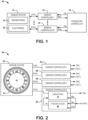
- FIG. 1 illustrates an example of a Coriolis vibratory gyroscope (CVG) system 10.
- the CVG system 10 can be implemented in any of a variety of applications with which accurate measurement of rotation may be necessary, such as aerospace navigation (e.g., in space environment).
- the CVG system 10 includes a sensor system 12, a gyroscope controller 14, and a plurality N of sensor controllers 16, where N is a positive integer greater than one.
- the electrodes 20 can include first electrodes provided as two sets of electrodes 20 that are arranged orthogonally with respect to each other, and can also include second electrodes 20 provided as two sets of electrodes 20 that are arranged orthogonally with respect to each other and at 45° relative to the first electrodes 20.
- Each of the sets of electrodes 20 can correspond to a respective one of N sensor channels 22 on which a forcer signal can be provided or from which a capacitive pickoff voltage can be monitored, as described in greater detail herein.
- a sensor channel 22 corresponds to one or more conductors that interconnect a respective one of the sensor controllers 16 one or more sets of the electrodes 20 of the sensor system 12 arranged along an axis of the oscillatory motion of the resonator 18.
- the sensor controllers 16 can each be configured to provide a sinusoidal forcer signal "F" on a respective one of the sensor channels 22 to a set of the electrodes 20 of the sensor system 12 to provide the oscillatory motion of the resonator 18, or can monitor a capacitive pickoff voltage "PO" from one of the sets of electrodes 20 via the respective one of the sensor channels 22.
- the sensor channels 22 are demonstrated as propagating signals "F/PO" to indicate that the sensor channels 22 can be implemented to either propagate a sinusoidal forcer signal F or propagate a pickoff voltage PO.
- a first portion of the sensor controllers 16 can correspond to one or more forcer mode controllers that are each configured to provide the sinusoidal forcer signal F via the respective sensor channel(s) 22, and a second portion of the sensor controllers 16 can correspond to one or more sensing mode controllers that are configured to monitor the capacitive pickoff voltage PO from the respective set of electrodes 20 that is arranged off-axis (e.g., orthogonal) with respect to the forcer electrodes 20 via the respective sensor channel 16.
- off-axis e.g., orthogonal
- the first portion of the sensor controllers 16 includes a field-programmable gate array (FPGA) that generates a sinusoidal signal via a capacitor array in response to a variable reference voltage generator, and includes a variable gain stage to generate the sinusoidal forcer signal F that is provided to the respective electrodes 20 via the sensor channel(s) 22.
- the capacitor array is arranged with sinusoidal weighting with respect to capacitance values to generate the sinusoidal signal.
- the variable reference voltage generator and the variable gain stage is controlled via a digital feedback signal, demonstrated in the example of FIG. 1 as a signal "FB".
- the digital feedback signal FB includes a fine adjust portion and a coarse adjust portion to adjust the variable reference voltage and the variable gain, respectively.
- the second portion of the sensor controllers 16 can include a first amplifier stage that is coupled to the respective sensor channel 22 to monitor the capacitive pickoff voltage PO.
- the second portion of the sensor controllers 16 can also include at least one additional variable gain stage configured to amplify the capacitive pickoff voltage PO, such as in response to a digital gain control signal, to generate a digital pickoff signal via an analog-to-digital converter (ADC).
- ADC analog-to-digital converter
- the digital pickoff signal is demonstrated as a signal DIG.
- the digital pickoff signal DIG can be implemented by the gyroscope controller 14 to generate the digital feedback signal FB that is provided to the respective first sensor controller(s) 16 that are associated with the orthogonal axis of oscillatory motion of the resonator(s) 18 to generate the sinusoidal forcer signal F.
- each of the sensor controllers 16 can be configured as pickoff/forcer controllers that are arranged substantially the same with respect to each other.
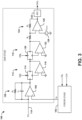
- FIG. 2 illustrates another example of a CVG system 50.
- the CVG system 50 can correspond to another example of the CVG system 10 in the example of FIG. 1 .
- the CVG system 50 can therefore be implemented in any of a variety of applications with which accurate measurement of rotation may be necessary, such as aerospace navigation (e.g., in space environment).
- the CVG system 50 includes a sensor system 52, as well as a plurality of sensor controllers, demonstrated in the example of FIG. 2 as a first sensor controller 54, a second sensor controller 56, a third sensor controller 58, and a fourth sensor controller 60.
- the sensor system 52 is demonstrated as an HRG having an annular resonator 61.
- the sensor system 52 can instead be arranged as any of a variety of different types of CVG sensor systems that includes one or more resonators that can be induced to move in an oscillatory manner.
- FIG. 1 the example of FIG.
- the sensory system 52 also includes a first set of electrodes 62 and a second set of electrodes 64 that are arranged orthogonally with respect to each other.
- the sensor system also includes a third set of electrodes 66 and a fourth set of electrodes 68 that are arranged orthogonally with respect to each other, and are arranged at 45° relative to the first set of electrodes 62 and the second set of electrodes 64.
- the sensor system 52 is coupled to the first sensor controller 54 via a first sensor channel 70.
- the first sensor channel 70 can be conductively coupled to the first set of electrodes 62.
- the sensor system 52 is coupled to the second sensor controller 56 via a second sensor channel 72.
- the second sensor channel 72 can be conductively coupled to the second set of electrodes 64.
- the sensor system 52 is coupled to the third sensor controller 58 via a third sensor channel 74.
- the third sensor channel 74 can be conductively coupled to the third set of electrodes 66.
- the sensor system 52 is coupled to the fourth sensor controller 60 via a fourth sensor channel 76.
- the fourth sensor channel 76 can be conductively coupled to the fourth set of electrodes 68. In the example of FIG.
- each of the sensor controllers 54, 56, 58, and 60 can generate a digital pickoff signal DIG that is provided to the gyroscope controller, and receives a set of digital control signals CNTL from the gyroscope controller 14.
- the set of digital control signals CNTL can include a digital gain control signal GN, a digital feedback signal FB, and a digital clock signal CLK.
- each of the sensor controllers 54, 56, 58, and 60 can be configured substantially the same with respect to each other. Therefore, each of the sensor controllers 54, 56, 58, and 60 can be configured to operate in a forcer mode or a sensing mode at a given time.
- the fourth sensor controller 60 is demonstrated in an exploded view to demonstrate that each of the sensor controllers 54, 56, 58, and 60 includes a gain stage 78 and a forcer stage 80.
- the gyroscope controller 14 can selectively control the sensor controllers 54, 56, 58, and 60 to operate in one of the forcer and sensing modes.
- the forcer stage 80 can be configured to generate a sinusoidal forcer voltage V F that is provided to the gain stage 78 to generate the sinusoidal forcer signal F that is provided on a respective one of the sensor channels 70, 72, 74, and 76.
- the sinusoidal forcer voltage V F can be generated in response to digital feedback signal FB and the digital clock signal CLK, such as via an FPGA and a capacitor array.
- the sensor controllers 54, 56, 58, and 60 that operate in the forcing mode can provide a sinusoidal forcer signal F on a respective one of the sensor channels 70, 72, 74, and 76 to a respective one of the sets of electrodes 62, 64, 66, and 68 of the sensor system 52 to provide the oscillatory motion of the resonator 61.
- the gain stage 78 can be configured to generate the digital pickoff signal DIG in response to the capacitive pickoff voltage PO that is provided from one of the sets of electrodes 62, 64, 66, and 68 via the respective one of the sensor channels 70, 72, 74, and 76 in response to the oscillatory motion of the resonator 61.
- the digital pickoff signal DIG can thus be implemented by the gyroscope controller 14 to generate the set of digital control signals CNTL (e.g., including the digital gain control signal GN, the digital feedback signal FB, and to implement phase control of the digital clock signal CLK). Therefore, the sensor controllers 54, 56, 58, and 60 that operate in the sensing mode can provide the digital pickoff signals DIG in response to the capacitive pickoff voltage PO resulting from the oscillatory motion of the resonator 61.
- the set of digital control signals CNTL e.g., including the digital gain control signal GN, the digital feedback signal FB, and to implement phase control of the digital clock signal CLK. Therefore, the sensor controllers 54, 56, 58, and 60 that operate in the sensing mode can provide the digital pickoff signals DIG in response to the capacitive pickoff voltage PO resulting from the oscillatory motion of the resonator 61.
- the gyroscope controller 14 can designate that the first and third sensor controllers 54 and 58 operate in the forcer mode at a given time, and that the second and fourth sensor controllers 56 and 60 operate in the sensing mode at the given time. Therefore, the forcer stages 80 of the sensor controllers 54 and 58 can each provide respective sinusoidal forcer signals F1 and F3 on the respective sensor channels 70 and 74 to generate an electrostatic force on the respective sets of electrodes 62 and 66 to provide the oscillatory motion of the resonator 61 during the given time.
- the gain stages 78 of the sensor controllers 56 and 60 can monitor the respective capacitive pickoff voltages PO 2 and PO 4 provided on the respective sensor channels 72 and 76 from the respective electrodes 64 and 68 resulting from the oscillatory motion of the resonator 61 to generate the respective digital pickoff signals DIG 2 and DIG 4 .
- the gyroscope controller 14 can switch the modes, such that the gyroscope controller 14 could then designate that the first and third sensor controllers 54 and 58 operate in the sensing mode, and that the second and fourth sensor controllers 56 and 60 could operate in the forcing mode. Therefore, the forcer stages 80 of the sensor controllers 56 and 60 can each provide respective sinusoidal forcer signals F2 and F4 on the respective sensor channels 72 and 76 to generate an electrostatic force on the respective sets of electrodes 64 and 68 to provide the oscillatory motion of the resonator 61.
- the gain stages 78 of the sensor controllers 54 and 58 can monitor the respective capacitive pickoff voltages PO 1 and PO 3 provided on the respective sensor channels 70 and 74 from the respective electrodes 62 and 66 resulting from the oscillatory motion of the resonator 61 to generate the respective digital pickoff signals DIG 1 and DIG 3 .
- FIG. 3 illustrates an example of a sensor system 100.
- the sensor system 100 is designated as the Xth sensor system of the plurality N of sensor systems 16 in the example of FIG. 1 , and can correspond to any of the sensor systems 54, 56, 58, and 60 in the example of FIG. 2 . Therefore, reference is to be made to the examples of FIGS. 1 and 2 in the following description of the example of FIG. 3 .
- the gain stage 104 includes a first amplifier stage 106 that includes an operational amplifier (OP-AMP) 108.
- the first amplifier stage 106 includes a resistor R 1 and a capacitor C 1 arranged in a feedback arrangement between an output and an inverting input of the OP-AMP 108.
- the first amplifier stage 106 is coupled to a respective one of the sensor channels 110 at a non-inverting input of the OP-AMP 108, and is therefore configured to provide an amplified version of the corresponding capacitive pickoff voltage PO X , as provided on the respective sensor channel 110.
- the amplified pickoff voltage is demonstrated as a signal V FA .
- the amplified pickoff voltage V FA is provided to a first variable amplifier stage 112 that includes a first digital potentiometer 114 and an OP-AMP 116.
- the first digital potentiometer 114 is arranged in a feedback arrangement between an output and an inverting input of the OP-AMP 116, such that the first digital potentiometer 114 provides a gain voltage V G1 to the inverting input of the OP-AMP 116, and the non-inverting input of the OP-AMP 116 is grounded.
- the first digital potentiometer 114 provides the gain voltage V G1 in response to a first digital gain signal GN 1 .
- the first digital gain control signal GN 1 can correspond to a first portion of the digital gain control signal GN demonstrated in the example of FIG. 2 . Therefore, the first digital potentiometer 114 is provided as a voltage-divider between the output of the OP-AMP 108 and the OP-AMP 116 to provide a second amplified pickoff voltage V FVA1 from the first variable amplifier stage 112.
- the second amplified pickoff voltage V FVA1 is provided to a second variable amplifier stage 118 that includes a second digital potentiometer 120 and an OP-AMP 122.
- the second digital potentiometer 120 is arranged in a feedback arrangement between an output and an inverting input of the OP-AMP 122, such that the second digital potentiometer 120 provides a gain voltage V G2 to the inverting input of the OP-AMP 122, and the non-inverting input of the OP-AMP 122 is grounded.
- the second digital potentiometer 120 provides the gain voltage V G2 in response to a second digital gain signal GN 2 .
- the second digital gain control signal GN 2 can correspond to a second portion of the digital gain control signal GN demonstrated in the example of FIG. 2 . Therefore, the second digital potentiometer 120 is provided as a voltage-divider between the output of the OP-AMP 116 and the OP-AMP 122 to provide a third amplified pickoff voltage V FVA2 from the second variable amplifier stage 118.
- the gain stage 104 also includes an offset amplifier stage 124 that is separated from the second variable gain amplifier stage 118 via a resistor R 2 .
- the offset amplifier stage 124 includes an OP-AMP 126 and a resistor R 3 that is arranged in a feedback arrangement between an output and an inverting input of the OP-AMP 126.
- the offset amplifier stage 124 also includes a voltage source 128 that provides an offset voltage V OFST to the non-inverting input of the OP-AMP 126. Therefore, the offset amplifier stage 124 provides a fourth amplified pickoff voltage V FVA3 to an ADC 130 that is configured to provide the corresponding respective digital pickoff signal DIG X in the sensing mode.
- the offset amplifier stage 124 is configured to provide the fourth amplified pickoff voltage V FVA3 as a level-shifted voltage to that is centered at an approximate center of an amplitude range of the ADC 130 to facilitate a non-differential output amplitude of the ADC 130.
- the gyroscope controller 14 can ignore the digital pickoff signal DIG X .
- the digital gain control signal GN includes the two separate portions GN 1 and GN 2 that are implemented to separately control the variable amplifier stages (e.g., the variable amplifier stages 112 and 118).
- the two separate variable amplifier stages 112 and 118 can be arranged in a cascaded manner and separately controlled by the respective portions GN 1 and GN 2 of the digital gain control signal GN to achieve a greater open loop gain bandwidth to achieve greater output linearity at the resonating frequency of the resonator of the sensor system 52, and thus the frequency of the capacitive pickoff signal PO X .
- a single variable amplifier stage with a singular control via the digital gain control signal GN, or additional variable amplifier stages can be implemented instead in the example of FIG. 3 .
- the digital gain control signal GN can provide the first and second portions at a first value to implement high gain of the respective pickoff signal PO X , such as to achieve a high resolution of the capacitive pickoff signal PO X via the digital pickoff signal DIG X .
- the gyroscope controller 14 can monitor the amplitude of the digital pickoff signal DIG X to provide feedback control of the gain and resolution of the digital pickoff signal DIG X .
- the gyroscope controller 14 can decrease the gain of the variable amplifier stages 112 and 118 via the respective portions GN 1 and GN 2 of the digital gain control signal GN. Accordingly, the gyroscope controller 14 can control the gain of the gain stage 104 with respect to the digital pickoff signal DIG X to determine rotation of the sensor system 52 about the input axis, as described in greater detail herein.
- the digital pickoff signal DIG X corresponds to a digital indication of the capacitance of the resonator(s) of the sensor system 52 with respect to the electrode(s) 62, 64, 66 or 68 to track the oscillatory motion of the resonator(s). Therefore, the digital pickoff signal DIG X can also be implemented by the gyroscope controller 14 to detect changes in the oscillatory motion of the resonator(s) which can correspond to rotation of the sensor system 52 about the sensitive axis.
- the gyroscope controller 14 can thus generate the feedback signal FB for a different sensor system (e.g., corresponding to a set of sensors arranged orthogonally with respect to the set of sensors coupled to the sensor channel 110) based on the digital pickoff signal DIG X .
- the feedback signal FB can thus be implemented for providing force-rebalance of the resonator(s) based on the digital pickoff signal DIG X .
- the gyroscope controller 14 can determine the rotation of the sensor system 52 about the sensitive axis based on the feedback signal FB, and thus based on the amount of force-rebalance necessary to provide the expected steady-state pickoff of the resonator(s) indicated by the digital pickoff signal DIG X , such as in a high-gain mode of the gain stage 104, as provided by the digital gain control signal GN (e.g., the first and second portions GN 1 and GN 2 ).
- the digital gain control signal GN e.g., the first and second portions GN 1 and GN 2
- the gyroscope controller 14 can determine the rotation of the sensor system 52 about the sensitive axis based on the digital pickoff signal DIG X in a non-feedback manner, such as in a low-gain mode of the gain stage 104, as provided by the digital gain control signal GN (e.g., the first and second portions GN 1 and GN 2 ). Therefore, the gyroscope controller 14 can determine the rotation of the sensor system 52 about the sensitive axis in either the low-gain mode or the high-gain mode while adaptively adjusting the gain to accommodate the open-loop bandwidth and output linearity of the gain stage 104.
- the digital gain control signal GN e.g., the first and second portions GN 1 and GN 2
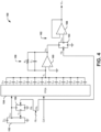
- FIG. 4 illustrates an example of a forcer stage 150.
- the forcer stage 150 is designated as part of the Yth sensor system of the plurality N of sensor systems 16 in the example of FIG. 1 to provide a sinusoidal forcer voltage V FY .
- the Yth sensor system 16 can correspond to a sensor system 16 that is associated with a set of electrodes 20 that is orthogonal with respect to the Xth sensor system 16 in the example of FIG. 3 , and can correspond to the forcer stage 80 in the example of FIG. 2 . Therefore, reference is to be made to the examples of FIGS. 1-3 in the following description of the example of FIG. 4 .
- the forcer stage 150 includes a variable reference voltage generator 152 and a field-programmable gate array (FPGA) 154.
- the variable reference voltage generator 152 is configured to generate a variable reference voltage V REF that drives the FPGA 154.
- the variable reference voltage generator 152 provides the variable reference voltage V REF based on a rail voltage Vcc and based on a control voltage V CTL that is provided from a digital potentiometer 156.
- the digital potentiometer 156 interconnects the variable reference voltage V REF and a low-voltage rail (e.g., ground) and is controlled by a digital feedback signal FB F that can correspond to a first portion of the digital feedback signal FB Y . Therefore, the digital potentiometer 156 acts as a voltage-divider with respect to the variable reference voltage V REF to provide the control voltage V CTL .
- the FPGA 154 is configured to generate a sinusoidal voltage V S based on the variable reference voltage V REF and based on the clock signal CLK.
- the clock signal CLK can have a frequency that is an integer harmonic of the natural resonance frequency of the resonator(s) of the sensor system 52.
- the sensor controller 16 that includes the forcer stage 150 can be set to the forcer mode based on the gyroscope controller 14 providing the clock signal CLK to the FPGA 154.
- the gyroscope controller 14 can provide phase control of the sinusoidal forcer voltage V FY based on providing the clocks signal CLK to the FPGA 154 at an appropriate time to generate the sinusoidal voltage V S , and thus the sinusoidal forcer voltage V FY , at a desired phase.
- the FPGA 154 can thus be configured to provide sinusoidal voltage V S via a capacitor array based on the clock signal CLK and having an amplitude based on the variable reference voltage V REF .
- the capacitor array is formed from capacitors C P1 through C P6 that provide the positive portions of the sinusoidal voltage V S and capacitors C N1 through C N6 that provide the negative portions of the sinusoidal voltage V S .
- the capacitors C N1 through C N6 and C P1 through C P6 can be sized in a numerically descending manner for sequential activation to construct the sinusoid of the sinusoidal voltage V S .
- the capacitors C N1 through C N6 and C P1 through C P6 can be sized such that the capacitance values are weighted in a sinusoidal fashion.
- the charges from the capacitors C N1 through C N6 and C P1 through C P6 are transferred to generate the sinusoidal voltage V S according to the sinusoidally-weighted capacitor values. Therefore, the sinusoidal voltage V S is generated in a stepped sinusoidal manner, such as with high spectral purity in a frequency band above the fundamentally generated frequency as a function of the number of capacitors (e.g., the sinusoidal steps) used in the input array.
- the amplitude stability of the generated sinusoidal voltage V S depends upon the ratio of the feedback capacitor C 2 and the capacitors C N1 through C N6 and C P1 through C P6 , which can be designed and implemented to be very stable over time and temperature such that high accuracy requirements can be met.
- the sinusoidal voltage V SA is provided through a first amplifier stage 158.
- the first amplifier stage 158 includes an OP-AMP 160.
- the first amplifier stage 158 also includes a resistor R 4 and a capacitor C 2 arranged in a feedback arrangement between an output and an inverting input of the OP-AMP 160.
- the first amplifier stage 158 is coupled to the capacitor array at the output of the FPGA 154 at a non-inverting input of the OP-AMP 160, and is therefore configured to provide the amplified sinusoidal voltage V SA by means of a sinusoidal up/down accumulation in the capacitor C 2 of the charges transferred by the sinusoidal-scaled capacitor array (capacitors C N1 through C N6 and capacitors C P1 through C P6 ) while the FPGA 154 is sequentially switching the outputs connected to the capacitor array between the reference voltage V REF and the low-voltage rail (e.g., ground).
- V REF sinusoidal-scaled capacitor array
- the forcer stage 150 also includes a variable gain stage 162 that includes a digital potentiometer 164 and an OP-AMP 166.
- the digital potentiometer 164 is arranged between the voltage V SA and a low-voltage rail (e.g., ground), and is controlled by a digital feedback signal FB C to provide a sinusoidal voltage V SVA corresponding to a variably attenuated version of the amplified sinusoidal voltage V SA .
- the digital feedback signal FB C can correspond to a second portion of the digital feedback signal FB Y .
- the sinusoidal voltage V SVA is provided to a non-inverting input of the OP-AMP 166, with the OP-AMP 166 having an output that is coupled to the inverting input in a feedback manner. Therefore, the OP-AMP 166 is configured to provide the sinusoidal forcer voltage V FY as a buffered version of the sinusoidal voltage V SVA .
- the digital feedback signal FB F can correspond to a first portion of the digital feedback signal FB Y
- the digital feedback signal FB C can correspond to a second portion of the digital feedback signal FB Y
- the first digital portion FB F can correspond to a fine adjustment of the amplitude of the sinusoidal forcer voltage V FY
- the second digital portion FB C can correspond to a coarse adjustment of the amplitude of the sinusoidal forcer voltage V FY .
- the gyroscope controller 14 can be configured to generate the digital feedback signal FB Y based on the digital pickoff voltage DIG X that is associated with a pickoff voltage PO X from a set of electrodes (e.g., the electrodes 64) that are orthogonal with respect to the electrodes (e.g., the electrodes 62) to which the sinusoidal forcer voltage V FY is applied. Therefore, the sinusoidal forcer voltage V FY can be provided to the respective set of electrodes (e.g., the electrodes 62) to provide a force-rebalance of the resonator(s) 18 to a steady-state (e.g., non-rotation of the sensor system 52 about the sensitive axis). The gyroscope controller 14 can thus generate the digital feedback signal FB Y , and thus the respective portions FB F and FB C , to provide the necessary amplitude of the sinusoidal forcer voltage V FY for force-rebalance.
- the gyroscope controller 14 can be configured to determine the rotation (e.g., rotation rate) of the sensor system 52 about the sensitive axis based on the determination of the necessary amplitude of the sinusoidal forcer voltage V FY for steady state force-rebalance. For example, the gyroscope controller 14 can determine the rotation based on one or a combination of all of the sinusoidal forcer voltages V F that are provided from the respective sensor systems 16 that operate in the forcer mode, such as during a high-gain mode associated with the respective gain stage (e.g., the gain stage 104) of the sensing controller 16 corresponding to the set of pickoff electrodes 20 arranged orthogonally with respect to the forcer electrodes 20 to which the sinusoidal forcer voltage V FY is applied.
- the rotation e.g., rotation rate
- the gyroscope controller 14 can maintain generation of the sinusoidal forcer voltage V FY , but can determine rotation of the sensor system 52 based on the digital pickoff signal DIG X .
- the gyroscope controller 14 can be configured to selectively control the modes of the sensor systems 16 to operate in either the forcer mode or the sensing mode.
- the gyroscope controller 14 can be configured to selectively provide the clock signal CLK to the FPGA 154 to set the respective sensor controller 16 that includes the forcer stage 150 to the forcer mode, or can cease providing the clock signal to the FPGA 154 to set the respective sensor controller 16 that includes the forcer stage 150 to the sensing mode.
- the gyroscope controller 14 can set the digital feedback signal FB Y to a value that corresponds to an approximately zero amplitude of the sinusoidal forcer voltage V FY (e.g., via the first and/or second portions FB F and/or FB C , respectively). Therefore, the gyroscope controller 14 can alternate the sensor controllers 16 that operate in the sensing and forcer modes, such as during real-time operation and/or in a calibration procedure, without using analog switches that can be ineffective in harsh environments (e.g., space).
- harsh environments e.g., space
- the forcer stage 150 can provide the sinusoidal forcer voltage V FY to a first amplifier stage of an associated gain stage of the respective sensor system 16 to provide the force-rebalance of the resonator(s) 18.
- the forcer stage 102 in response to the forcer stage 102 being set to the forcer mode via the clock signal CLK, the forcer stage 102 provides the sinusoidal forcer voltage V F to the first amplifier stage 106 via the non-inverting input of the OP-AMP 108.
- the OP-AMP 108 thus provides an amplified version of the sinusoidal forcer voltage V F to the respective sensor channel 110 via the feedback arrangement of the resistor R 1 and the capacitor C 1 .
- the gyroscope controller 14 can ignore the digital pickoff signal DIG X . Therefore, the sensor system 100 can be set to either the forcer mode or the sensing mode based on the amplitude of the sinusoidal forcer voltage V F (e.g., based on the presence or absence of the clock signal CLK).
- a CVG sensor system 10 that exhibits simple digital control.
- the digital control of the CVG sensor system 10 allows for high-resolution, low-cost, greater efficiency, and simpler configurability relative to other typical CVG sensor systems.
- the CVG sensor system 10 can provide for variation in operation of the electrodes between use for pickoff and use for force-rebalance based on the selectivity of the sensor controllers 16 between the forcer mode and the pickoff mode.
- the selectivity of the sensor controllers 16 between the forcer mode and the pickoff mode based on providing the digital clock signal CLK or not providing the digital clock signal CLK, the CVG sensor system 10 can operate in harsh environments (e.g., space) that can prohibit the use of analog switches for providing such selectivity.
- FIG. 5 a methodology in accordance with various aspects of the present invention will be better appreciated with reference to FIG. 5 . While, for purposes of simplicity of explanation, the methodology of FIG. 5 is shown and described as executing serially, it is to be understood and appreciated that the present invention is not limited by the illustrated order, as some aspects could, in accordance with the present invention, occur in different orders and/or concurrently with other aspects from that shown and described herein. Moreover, not all illustrated features may be required to implement a methodology in accordance with an aspect of the present invention.
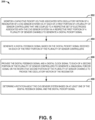
- FIG. 5 illustrates an example of a method 200 for controlling a CVG system (e.g., the CVG system 10).
- a capacitive pickoff voltage e.g., the capacitive pickoff voltage PO
- a resonator e.g., the resonator(s) 18
- a CVG sensor system e.g., the sensor system 12
- a respective set of electrodes e.g., the electrodes 20
- a digital pickoff signal e.g., the digital pickoff voltage DIG
- a digital feedback signal (e.g., the digital feedback signal FB) is generated based on the digital pickoff signal received via each of the first portion of the plurality of sensor controllers.
- the digital feedback signal and a digital clock signal (e.g., the digital clock signal CLK) is provided to each of a second portion of the plurality of sensor controllers to generate a sinusoidal forcer signal (e.g., the sinusoidal forcer voltage V F ) on the respective second portion of the plurality of sensor channels to provide the oscillatory motion of the resonator.
- a rotation about the CVG sensor system is determined based on at least one of the digital feedback signal and the digital pickoff signal.
- a Coriolis vibratory gyroscope (CVG) control system comprising: a plurality of sensor controllers that are each coupled to a respective set of electrodes associated with a CVG sensor system via one of a respective plurality of sensor channels, a first portion of the plurality of sensor controllers being configured to provide a sinusoidal forcer signal on the respective one of the plurality of sensor channels in response to a digital clock signal and a digital feedback signal to provide oscillation of a resonator associated with the CVG sensor system, a second portion of the plurality of sensor controllers being configured to monitor a capacitive pickoff voltage associated with the resonator of the CVG sensor system on the respective one of the plurality of sensor channels to generate a digital pickoff signal; and a gyroscope controller configured to generate the digital feedback signal in response to the digital pickoff signal from the second portion of the plurality of sensor controllers and to provide the digital feedback signal and the digital clock signal to the first portion of the plurality of
- the plurality of sensor controllers may be configured as a plurality of pickoff/forcer controllers that are arranged substantially the same with respect to each other, wherein the first portion of the plurality of pickoff/forcer controllers may be configured to provide the sinusoidal forcer signal on the respective one of the plurality of sensor channels in response to the digital clock signal and the digital feedback signal in a forcer mode, wherein the second portion of the plurality of pickoff/forcer controllers may be configured to monitor the capacitive pickoff voltage on the respective one of the plurality of sensor channels to generate the digital pickoff signal in a sensing mode, wherein the gyroscope controller may be configured to selectively switch the plurality of pickoff/forcer controllers between the forcer mode and the sensing mode.
- Each of the plurality of sensor controllers may comprise: a gain stage comprising an amplifier stage that is coupled to the respective one of the plurality of sensor channels, the amplifier stage being configured to monitor the capacitive pickoff voltage on the respective one of the plurality of sensor channels to generate the digital pickoff signal in the sensing mode; and a forcer stage coupled to the amplifier stage, the forcer stage being configured to generate the sinusoidal forcer signal in response to the digital feedback signal and the digital clock signal, and to provide the sinusoidal forcer signal to the amplifier stage to provide the sinusoidal forcer signal on the respective one of the plurality of sensor channels in the forcer mode.
- the amplifier stage may be a first amplifier stage, the gain stage further comprising: at least one programmable gain stage configured to generate a variable gain amplified pickoff voltage based on an amplified pickoff voltage provided by the first amplifier stage in response to a digital gain control signal provided by the gyroscope controller; and an analog-to-digital converter (ADC) configured to generate the digital pickoff signal based on the variable gain amplified pickoff voltage.
- ADC analog-to-digital converter
- the forcer stage may comprise: a field-programmable gate array (FPGA) configured to generate a sinusoidal signal via a sinusoidally-weighted capacitor array in response to the digital clock signal and a variable reference voltage controlled via a fine adjustment portion of the digital feedback signal; a second amplifier stage configured to amplify the sinusoidal signal to generate an amplified sinusoidal signal; and a variable amplifier stage configured to generate the sinusoidal forcer signal based on the amplified sinusoidal signal and in response to a coarse adjustment portion of the digital feedback signal.
- FPGA field-programmable gate array
- the second portion of the plurality of sensor controllers may comprise: a first amplifier stage coupled to the respective one of the plurality of sensor channels, the first amplifier stage being configured to generate an amplified pickoff voltage based on the capacitive pickoff voltage; at least one programmable gain stage configured to generate a variable gain amplified pickoff voltage based on the amplified pickoff voltage in response to a digital gain control signal provided by the gyroscope controller; and an analog-to-digital converter (ADC) configured to generate the digital pickoff signal based on the variable gain amplified pickoff voltage.
- ADC analog-to-digital converter
- the at least one programmable gain stage may comprise: a first programmable gain stage coupled to the first amplifier stage and comprising a first variable resistor and a first operational amplifier, the first variable resistor being controlled by a first portion of the digital gain control signal; and a second programmable gain stage coupled to the first programmable gain stage and comprising a second variable resistor and a second operational amplifier, the second variable resistor being controlled by a second portion of the digital gain control signal.
- the second portion of the plurality of sensor controllers may further comprise an offset amplifier stage configured to provide level-shifting of the variable gain amplified pickoff voltage with respect to an input of the ADC.
- the gyroscope controller may be configured to determine the rotation about the CVG sensor system based on the digital feedback signal in a high gain mode associated with the at least one variable gain amplifier stage based on the digital gain control signal, wherein the gyroscope controller may also be configured to monitor the digital pickoff signal and to decrease the gain of at least one programmable gain stage in a low gain mode via the digital gain control signal in response to detecting saturation of the ADC with respect to the variable gain amplified pickoff signal, the gyroscope controller being further configured to determine the rotation about the CVG sensor system based on the digital pickoff signal in the low gain mode.
- the second portion of the plurality of sensor controllers may comprise: a field-programmable gate array (FPGA) configured to generate a sinusoidal signal via a sinusoidally-weighted capacitor array in response to the digital clock signal and a variable reference voltage controlled via a fine adjustment portion of the digital feedback signal; a first amplifier stage configured to amplify the sinusoidal signal to generate an amplified sinusoidal signal; and a variable amplifier stage configured to generate the sinusoidal forcer signal based on the amplified sinusoidal signal and in response to a coarse adjustment portion of the digital feedback signal.
- FPGA field-programmable gate array
- the second portion of the plurality of sensor controllers may further comprise: a variable voltage source configured to generate the variable reference voltage based on a high-voltage rail; and a digital potentiometer configured to provide a control voltage to the variable voltage source based on the variable reference voltage in a feedback manner in response to the fine adjustment portion of the digital feedback signal.
- the variable amplifier stage may comprise a digital potentiometer interconnecting the amplified sinusoidal signal and an operational amplifier arranged in a feedback manner and configured to generate the sinusoidal forcer signal, the digital potentiometer being controlled via the coarse adjustment portion of the digital feedback signal.
Landscapes
- Engineering & Computer Science (AREA)
- Physics & Mathematics (AREA)
- General Physics & Mathematics (AREA)
- Radar, Positioning & Navigation (AREA)
- Remote Sensing (AREA)
- Signal Processing (AREA)
- Gyroscopes (AREA)
Claims (10)
- Coriolis-Vibrationsgyroskop(CVG)-Steuersystem (10), das Folgendes umfasst:
eine Vielzahl von Sensorsteuerungen (16), die jeweils mit einem jeweiligen Satz von einem CVG-Sensorsystem (12) zugeordneten Elektroden (20) über einen von einer jeweiligen Vielzahl von Sensorkanälen gekoppelt sind, wobei ein erster Teil der Vielzahl von Sensorsteuerungen zum Bereitstellen eines sinusförmigen Forcer-Signals auf dem jeweiligen einen der Vielzahl von Sensorkanälen als Reaktion auf ein digitales Taktsignal und ein digitales Feedback-Signal konfiguriert ist, um Oszillation eines dem CVG-Sensorsystem zugeordneten Resonators bereitzustellen, wobei ein zweiter Teil der Vielzahl von Sensorsteuerungen zum Überwachen (202) einer dem Resonator des CVG-Sensorsystems zugeordneten kapazitiven Abgriffspannung auf dem jeweiligen einen der Vielzahl von Sensorkanälen konfiguriert ist, um ein digitales Abgriffsignal zu erzeugen, wobei jede der Vielzahl von Sensorsteuerungen Folgendes einschließt:eine Verstärkungsstufe (78), die eine mit dem jeweiligen einen der Vielzahl von Sensorkanälen gekoppelte erste Verstärkerstufe, wobei die erste Verstärkerstufe zum Überwachen der kapazitiven Abgriffspannung auf dem jeweiligen einen der Vielzahl von Sensorkanälen konfiguriert ist, um das digitale Abgriffsignal in einem Erfassungsmodus zu erzeugen; mindestens eine programmierbare Verstärkungsstufe, konfiguriert zum Erzeugen einer verstärkten Abgriffspannung mit variabler Verstärkung auf der Basis einer verstärkten Abgriffspannung, die von der ersten Verstärkerstufe als Reaktion auf ein digitales Verstärkungssteuersignal bereitgestellt ist; und einen Analog-Digital-Wandler, ADC (130), umfasst, konfiguriert zum Erzeugen des digitalen Abgriffsignals auf der Basis der verstärkten Abgriffspannung mit variabler Verstärkung; undeine Forcer-Stufe (80), die mit der ersten Verstärkerstufe gekoppelt ist, wobei die Forcer-Stufe ein Field-Programmable-Gate-Array FPGA (154), konfiguriert zum Erzeugen eines sinusförmigen Signals über ein sinusförmig gewichtetes Kondensator-Array als Reaktion auf das digitale Taktsignal und eine über einen Feineinstellungsteil des digitalen Feedback-Signals gesteuerte variable Referenzspannung; eine zweite Verstärkerstufe (158), konfiguriert zum Verstärken des sinusförmigen Signals, um ein verstärktes sinusförmiges Signal zu erzeugen; und eine variable Verstärkerstufe (162) umfasst, konfiguriert zum Erzeugen des sinusförmigen Forcer-Signals auf der Basis des verstärkten sinusförmigen Signals und als Reaktion auf einen Grobeinstellungsteil des digitalen Feedback-Signals und des digitalen Taktsignals, wobei die Forcer-Stufe zum Bereitstellen des sinusförmigen Forcer-Signals an die erste Verstärkerstufe konfiguriert ist, um das sinusförmige Forcer-Signal auf dem jeweiligen einen der Vielzahl von Sensorkanälen in einem Forcer-Modus bereitzustellen; undeine Gyroskopsteuerung (14), konfiguriert zum Erzeugen (204) des digitalen Feedback-Signals als Reaktion auf das digitale Abgriffsignal vom zweiten Teil der Vielzahl von Sensorsteuerungen und zum Bereitstellen (206) des digitalen Feedback-Signals und des digitalen Taktsignals an den ersten Teil der Vielzahl von Sensorsteuerungen, und zum Bestimmen (208) einer Drehung um das CVG-Sensorsystem auf der Basis mindestens eines des digitalen Feedback-Signals und des digitalen Abgriffsignals,wobei die Vielzahl von Sensorsteuerungen als eine Vielzahl von Abgriff-/Forcer-Steuerungen konfiguriert ist, die im Wesentlichen gleich zueinander angeordnet sind, wobei der erste Teil der Vielzahl von Abgriff-/Forcer-Steuerungen zum Bereitstellen des sinusförmigen Forcer-Signals auf dem jeweiligen einen der Vielzahl von Sensorkanälen als Reaktion auf das digitale Taktsignal und das digitale Feedback-Signal im Forcer-Modus konfiguriert ist, wobei der zweite Teil der Vielzahl von Abgriff-/Forcer-Steuerungen zum Überwachen der kapazitiven Abgriffspannung auf dem jeweiligen einen der Vielzahl von Sensorkanälen konfiguriert ist, um das digitale Abgriffsignal im Erfassungsmodus zu erzeugen, wobei die Gyroskopsteuerung zum selektiven Umschalten der Vielzahl von Abgriff-/Forcer-Steuerungen zwischen dem Forcer-Modus und dem Erfassungsmodus konfiguriert ist. - System nach Anspruch 1, wobei der zweite Teil der Vielzahl von Sensorsteuerungen Folgendes umfasst:eine erste Verstärkerstufe, die mit dem jeweiligen einen der Vielzahl von Sensorkanälen gekoppelt ist, wobei die erste Verstärkerstufe zum Erzeugen einer verstärkten Abgriffspannung auf der Basis der kapazitiven Abgriffspannung konfiguriert ist;mindestens eine programmierbare Verstärkungsstufe, konfiguriert zum Erzeugen einer verstärkten Abgriffspannung mit variabler Verstärkung auf der Basis der verstärkten Abgriffspannung als Reaktion auf ein von der Gyroskopsteuerung bereitgestelltes digitales Verstärkungssteuersignal; undeinen Analog-Digital-Wandler, ADC, der zum Erzeugen des digitalen Abgriffsignals auf der Basis der verstärkten Abgriffspannung mit variabler Verstärkung konfiguriert ist.
- System nach Anspruch 2, wobei mindestens eine programmierbare Verstärkungsstufe Folgendes umfasst:eine erste programmierbare Verstärkungsstufe, die mit der ersten Verstärkerstufe gekoppelt ist und einen ersten variablen Widerstand und einen ersten Operationsverstärker umfasst, wobei der erste variable Widerstand durch einen ersten Teil des digitalen Verstärkungssteuersignals gesteuert wird; undeine zweite programmierbare Verstärkungsstufe, die mit der ersten programmierbaren Verstärkungsstufe gekoppelt ist und einen zweiten variablen Widerstand und einen zweiten Operationsverstärker umfasst, wobei der zweite variable Widerstand durch einen zweiten Teil des digitalen Verstärkungssteuersignals gesteuert wird.
- System nach Anspruch 2 oder 3, wobei der zweite Teil der Vielzahl von Sensorsteuerungen ferner eine Offset-Verstärkerstufe umfasst, die zum Bereitstellen einer Pegelverschiebung der verstärkten Abgriffspannung mit variabler Verstärkung in Bezug auf einen Eingang des ADC konfiguriert ist.
- System nach einem der Ansprüche 2 bis 4, wobei die Gyroskopsteuerung zum Bestimmen der Drehung um das CVG-Sensorsystem auf der Basis des digitalen Feedback-Signals in einem Hochverstärkungsmodus konfiguriert ist, der der mindestens einen Verstärkerstufe mit variabler Verstärkung auf der Basis des digitalen Verstärkungssteuersignals zugeordnet ist, wobei die Gyroskopsteuerung auch zum Überwachen des digitalen Abgriffsignals und zum Verringern der Verstärkung mindestens einer programmierbaren Verstärkungsstufe in einem Niederverstärkungsmodus über das digitale Verstärkungssteuersignal als Reaktion auf das Erkennen einer Sättigung des ADC in Bezug auf das verstärkte Abgriffsignal mit variabler Verstärkung konfiguriert ist, wobei die Gyroskopsteuerung ferner zum Bestimmen der Drehung um das CVG-Sensorsystem auf der Basis des digitalen Abgriffsignals im Niederverstärkungsmodus konfiguriert ist.
- System nach den Ansprüchen 2 bis 5, wobei der zweite Teil der Vielzahl von Sensorsteuerungen Folgendes umfasst:ein Field-Programmable-Gate-Array, FPGA, konfiguriert zum Erzeugen eines sinusförmigen Signals über ein sinusförmig gewichtetes Kondensator-Array als Reaktion auf das digitale Taktsignal und eine über einen Feineinstellungsteil des digitalen Feedback-Signals gesteuerte variable Referenzspannung;eine erste Verstärkerstufe, die zum Verstärken des sinusförmigen Signals konfiguriert ist, um ein verstärktes sinusförmiges Signal zu erzeugen; undeine variable Verstärkerstufe, die zum Erzeugen des sinusförmigen Forcer-Signals auf der Basis des verstärkten sinusförmigen Signals und als Reaktion auf einen Grobeinstellungsteil des digitalen Feedback-Signals konfiguriert ist.
- System nach Anspruch 6, wobei der zweite Teil der Vielzahl von Sensorsteuerungen ferner Folgendes umfasst:eine variable Spannungsquelle, konfiguriert zum Erzeugen der variablen Referenzspannung auf der Basis einer Hochspannungsschiene; undein digitales Potentiometer, konfiguriert zum Bereitstellen einer Steuerspannung an die variable Spannungsquelle auf der Basis der variablen Referenzspannung auf eine Feedback-Weise als Reaktion auf den Feineinstellungsteil des digitalen Feedback-Signals.
- System nach Anspruch 6 oder 7, wobei die variable Verstärkerstufe ein digitales Potentiometer umfasst, das das verstärkte sinusförmige Signal und einen Operationsverstärker miteinander verbindet, der in einer Feedback-Weise angeordnet und zum Erzeugen des sinusförmigen Forcer-Signals konfiguriert ist, wobei das digitale Potentiometer über den Grobeinstellungsteil des digitalen Feedback-Signals gesteuert wird.
- Verfahren zum Steuern eines Coriolis-Vibrationsgyroskop(CVG)-Systems (10), wobei das Verfahren Folgendes umfasst:Überwachen (202) einer kapazitiven Abgriffspannung, die einer Oszillationsbewegung eines Resonators eines CVG-Sensorsystems (12) zugeordnet ist, an jedem von einem ersten Teil einer Vielzahl von Sensorsteuerungen (16), die mit einem jeweiligen Satz von dem CVG-Sensorsystem zugeordneten Elektroden (20) über einen jeweiligen ersten Teil einer Vielzahl von Sensorkanälen gekoppelt sind, um ein digitales Abgriffsignal zu erzeugen;Erzeugen (204) eines digitalen Feedback-Signals auf der Basis des digitalen Abgriffsignals, das über jeden vom ersten Teil der Vielzahl von Sensorsteuerungen empfangen wird;Bereitstellen (206) eines Feineinstellungsteils des digitalen Feedback-Signals an ein digitales Potentiometer, um eine Amplitude einer variablen Referenzspannung an ein Field-Programmable-Gate-Array zu steuern, das zum Erzeugen eines sinusförmigen Signals mit variabler Amplitude über ein sinusförmig gewichtetes Kondensator-Array als Reaktion auf das digitale Taktsignal und die variable Referenzspannung konfiguriert ist;Bereitstellen eines Grobeinstellungsteils des digitalen Feedback-Signals an eine variable Verstärkerstufe, die zum Erzeugen eines sinusförmigen Forcer-Signals auf der Basis des sinusförmigen Signals konfiguriert ist;Bereitstellen eines digitalen Taktsignals an jeden von einem zweiten Teil der Vielzahl von Sensorsteuerungen, um das sinusförmige Forcer-Signal auf dem jeweiligen zweiten Teil der Vielzahl von Sensorkanälen zu erzeugen, um die Oszillationsbewegung des Resonators bereitzustellen; undBestimmen (208) einer Drehung um das CVG-Sensorsystem auf der Basis von mindestens einem der digitalen Feedback-Signale und dem digitalen Abgriffsignal,wobei die Vielzahl von Sensorsteuerungen als eine Vielzahl von Abgriff-/Forcer-Steuerungen konfiguriert ist, die im Wesentlichen gleich zueinander angeordnet sind, sodass der erste Teil der Vielzahl von Abgriff-/Forcer-Steuerungen in einem Erfassungsmodus arbeitet und der zweite Teil der Vielzahl von Abgriff-/Forcer-Steuerungen in einem Forcer-Modus arbeitet, wobei das Verfahren ferner das selektive Umschalten der Vielzahl von Abgriff-/Forcer-Steuerungen zwischen dem Forcer-Modus und dem Erfassungsmodus umfasst.
- Verfahren nach Anspruch 9, das ferner Folgendes umfasst:Bereitstellen eines digitalen Verstärkungssteuersignals an mindestens eine programmierbare Verstärkungsstufe, die jedem vom ersten Teil der Vielzahl von Sensorsteuerungen zugeordnet ist, um eine verstärkte Abgriffspannung mit variabler Verstärkung auf der Basis der kapazitiven Abgriffspannung zu erzeugen; undErzeugen des digitalen Abgriffsignals auf der Basis der verstärkten Abgriffspannung mit variabler Verstärkung über einen Analog-Digital-Wandler.
Applications Claiming Priority (1)
| Application Number | Priority Date | Filing Date | Title |
|---|---|---|---|
| US16/249,478 US11073393B2 (en) | 2019-01-16 | 2019-01-16 | Coriolis vibratory gyroscope control system |
Publications (2)
| Publication Number | Publication Date |
|---|---|
| EP3686554A1 EP3686554A1 (de) | 2020-07-29 |
| EP3686554B1 true EP3686554B1 (de) | 2025-05-07 |
Family
ID=69172741
Family Applications (1)
| Application Number | Title | Priority Date | Filing Date |
|---|---|---|---|
| EP20152043.4A Active EP3686554B1 (de) | 2019-01-16 | 2020-01-15 | Coriolis-vibrationskreiselsteuersystem |
Country Status (2)
| Country | Link |
|---|---|
| US (1) | US11073393B2 (de) |
| EP (1) | EP3686554B1 (de) |
Families Citing this family (2)
| Publication number | Priority date | Publication date | Assignee | Title |
|---|---|---|---|---|
| US11073391B2 (en) | 2019-09-26 | 2021-07-27 | Northrop Grumman Systems Corporation | Coriolis vibratory accelerometer system |
| CN116466634A (zh) * | 2023-04-23 | 2023-07-21 | 东南大学 | 基于参数平均模型的微半球谐振陀螺数字控制电路装置 |
Family Cites Families (24)
| Publication number | Priority date | Publication date | Assignee | Title |
|---|---|---|---|---|
| US4968989A (en) | 1987-04-20 | 1990-11-06 | Olmstead John A | Switched capacitor filter for use with a digital-to-analog (D/A) converter |
| US5168756A (en) | 1991-02-08 | 1992-12-08 | Sundstrand Corporation | Dithering coriolis rate and acceleration sensor utilizing a permanent magnet |
| WO2004085963A1 (en) | 2003-03-28 | 2004-10-07 | Bae Systems Plc | A rate sensing device |
| DE10360962B4 (de) | 2003-12-23 | 2007-05-31 | Litef Gmbh | Verfahren zur Quadraturbias-Kompensation in einem Corioliskreisel sowie dafür geeigneter Corioliskreisel |
| US7318347B2 (en) | 2005-05-09 | 2008-01-15 | Northrop Grumman Corporation | Hemispherical resonator gyro control |
| US7281426B1 (en) * | 2006-06-15 | 2007-10-16 | Innalabs Technologies, Inc. | Stemless hemispherical resonator gyroscope |
| FR2920224B1 (fr) | 2007-08-23 | 2009-10-02 | Sagem Defense Securite | Procede de determination d'une vitesse de rotation d'un capteur vibrant axisymetrique, et dispositif inertiel mettant en oeuvre le procede |
| FR2925669B1 (fr) | 2007-12-21 | 2010-01-15 | Sagem Defense Securite | Mesure par systeme gyroscopique |
| US7874209B2 (en) | 2008-01-08 | 2011-01-25 | Northrop Grumman Guidance And Electronics Company, Inc. | Capacitive bulk acoustic wave disk gyroscopes with self-calibration |
| US8205495B2 (en) * | 2008-06-10 | 2012-06-26 | The Boeing Company | Systematic disc resonator gyroscope tuning |
| US7912664B2 (en) | 2008-09-11 | 2011-03-22 | Northrop Grumman Guidance And Electronics Company, Inc. | Self calibrating gyroscope system |
| US8567247B2 (en) | 2009-10-12 | 2013-10-29 | The Regents Of The University Of California | Three-dimensional wafer-scale batch-micromachined sensor and method of fabrication for the same |
| US9229026B2 (en) | 2011-04-13 | 2016-01-05 | Northrop Grumman Guaidance and Electronics Company, Inc. | Accelerometer systems and methods |
| US8763441B2 (en) | 2011-11-22 | 2014-07-01 | Georgia Tech Research Corporation | Method and apparatus for self-calibration of gyroscopes |
| US10247554B2 (en) * | 2014-09-24 | 2019-04-02 | The Regents Of The University Of California | Fully balanced micro-machined inertial sensor |
| US9534897B2 (en) | 2015-01-12 | 2017-01-03 | The Boeing Company | High bandwidth Coriolis vibratory gyroscope (CVG) with in-situ bias self-calibration |
| US9702697B2 (en) | 2015-02-10 | 2017-07-11 | Northrop Grumman Systems Corporation | Bias and scale-factor error mitigation in a Coriolis vibratory gyroscope system |
| US20170153266A1 (en) | 2015-11-30 | 2017-06-01 | Lumedyne Technologies Incorporated | Systems and methods for determining inertial parameters using integration |
| US10393522B2 (en) | 2016-07-12 | 2019-08-27 | Invensense, Inc. | Sensor with low power with closed-loop-force-feedback loop |
| US10228264B2 (en) | 2016-09-02 | 2019-03-12 | Northrop Grumman Systems Corporation | Self-calibration of an inertial system |
| US10514258B2 (en) | 2016-09-09 | 2019-12-24 | Nextnav, Llc | Systems and methods for calibrating unstable sensors |
| US10584967B2 (en) | 2016-10-18 | 2020-03-10 | Northrop Grumman Systems Corporation | Hemispherical resonator gyroscope |
| US20180156634A1 (en) | 2016-12-02 | 2018-06-07 | Northrop Grumman Systems Corporation | Dual-vibratory pattern resonator gyroscope |
| US11073391B2 (en) | 2019-09-26 | 2021-07-27 | Northrop Grumman Systems Corporation | Coriolis vibratory accelerometer system |
-
2019
- 2019-01-16 US US16/249,478 patent/US11073393B2/en active Active
-
2020
- 2020-01-15 EP EP20152043.4A patent/EP3686554B1/de active Active
Also Published As
| Publication number | Publication date |
|---|---|
| US20200225039A1 (en) | 2020-07-16 |
| EP3686554A1 (de) | 2020-07-29 |
| US11073393B2 (en) | 2021-07-27 |
Similar Documents
| Publication | Publication Date | Title |
|---|---|---|
| US10914585B1 (en) | High dynamic range gyroscope | |
| US6079272A (en) | Gyroscopes and compensation | |
| US5911156A (en) | Split electrode to minimize charge transients, motor amplitude mismatch errors, and sensitivity to vertical translation in tuning fork gyros and other devices | |
| US6253612B1 (en) | Generation of mechanical oscillation applicable to vibratory rate gyroscopes | |
| US8042393B2 (en) | Arrangement for measuring a rate of rotation using a vibration sensor | |
| US8875577B2 (en) | Oscillator circuit, method for manufacturing oscillator circuit, inertial sensor using the oscillator circuit, and electronic device | |
| EP1840508B1 (de) | Adaptive Schaltungen und Verfahren zur Verminderung von schwingungs- oder stoßinduzierten Fehlern bei Inertialsensoren | |
| US6837108B2 (en) | Increasing the dynamic range of a MEMS gyroscope | |
| KR100523650B1 (ko) | 진동회전센서전자장치내정량화잡음을줄이기위한제어방법및그장치 | |
| US6470748B1 (en) | Feedback mechanism for rate gyroscopes | |
| EP3686554B1 (de) | Coriolis-vibrationskreiselsteuersystem | |
| US8424382B2 (en) | Microelectromechanical sensor and operating method for a microelectromechanical sensor | |
| US7347096B2 (en) | Digital accelerometer | |
| Marra et al. | Single-resonator, time-switched FM MEMS accelerometer with theoretical offset drift complete cancellation | |
| US9234907B2 (en) | Angular rate sensor with improved aging properties | |
| EP4113060A1 (de) | Ansteuerschaltung zur ansteuerung eines resonanten mems-oszillators | |
| Padovani et al. | In-plane and out-of-plane FM accelerometers with 130 DB dynamic range through nems-based oscillators | |
| Eminoglu et al. | Ratio-metric readout technique for MEMS gyroscopes with force feedback | |
| Zhao et al. | An interface ASIC for an atmospheric-pressure MEMS gyroscope with PLL-based phase adjustment and SC amplitude regulation | |
| Saukoski et al. | Readout and control electronics for a microelectromechanical gyroscope | |
| US12203774B2 (en) | Trim circuit and method of oscillator drive circuit phase calibration | |
| RU2147751C1 (ru) | Чувствительный элемент устройства для измерения линейного ускорения | |
| Marx et al. | A Closed-Loop MEMS Gyroscope with Optimized Electronics for Achieving sub-2 m°/√ h Angular Random Walk and sub-4 m°/h Bias Instability | |
| JP2008157767A (ja) | 加速度検出装置 | |
| Lin et al. | A robust triangular-electrode based capacitive detection method for MEMS gyroscopes |
Legal Events
| Date | Code | Title | Description |
|---|---|---|---|
| PUAI | Public reference made under article 153(3) epc to a published international application that has entered the european phase |
Free format text: ORIGINAL CODE: 0009012 |
|
| STAA | Information on the status of an ep patent application or granted ep patent |
Free format text: STATUS: REQUEST FOR EXAMINATION WAS MADE |
|
| 17P | Request for examination filed |
Effective date: 20200115 |
|
| AK | Designated contracting states |
Kind code of ref document: A1 Designated state(s): AL AT BE BG CH CY CZ DE DK EE ES FI FR GB GR HR HU IE IS IT LI LT LU LV MC MK MT NL NO PL PT RO RS SE SI SK SM TR |
|
| AX | Request for extension of the european patent |
Extension state: BA ME |
|
| STAA | Information on the status of an ep patent application or granted ep patent |
Free format text: STATUS: EXAMINATION IS IN PROGRESS |
|
| P01 | Opt-out of the competence of the unified patent court (upc) registered |
Effective date: 20230607 |
|
| 17Q | First examination report despatched |
Effective date: 20230621 |
|
| GRAP | Despatch of communication of intention to grant a patent |
Free format text: ORIGINAL CODE: EPIDOSNIGR1 |
|
| STAA | Information on the status of an ep patent application or granted ep patent |
Free format text: STATUS: GRANT OF PATENT IS INTENDED |
|
| INTG | Intention to grant announced |
Effective date: 20241205 |
|
| GRAS | Grant fee paid |
Free format text: ORIGINAL CODE: EPIDOSNIGR3 |
|
| GRAA | (expected) grant |
Free format text: ORIGINAL CODE: 0009210 |
|
| STAA | Information on the status of an ep patent application or granted ep patent |
Free format text: STATUS: THE PATENT HAS BEEN GRANTED |
|
| AK | Designated contracting states |
Kind code of ref document: B1 Designated state(s): AL AT BE BG CH CY CZ DE DK EE ES FI FR GB GR HR HU IE IS IT LI LT LU LV MC MK MT NL NO PL PT RO RS SE SI SK SM TR |
|
| REG | Reference to a national code |
Ref country code: GB Ref legal event code: FG4D |
|
| REG | Reference to a national code |
Ref country code: CH Ref legal event code: EP |
|
| REG | Reference to a national code |
Ref country code: DE Ref legal event code: R096 Ref document number: 602020050689 Country of ref document: DE |
|
| REG | Reference to a national code |
Ref country code: IE Ref legal event code: FG4D |
|
| REG | Reference to a national code |
Ref country code: NL Ref legal event code: MP Effective date: 20250507 |
|
| PG25 | Lapsed in a contracting state [announced via postgrant information from national office to epo] |
Ref country code: PT Free format text: LAPSE BECAUSE OF FAILURE TO SUBMIT A TRANSLATION OF THE DESCRIPTION OR TO PAY THE FEE WITHIN THE PRESCRIBED TIME-LIMIT Effective date: 20250908 Ref country code: FI Free format text: LAPSE BECAUSE OF FAILURE TO SUBMIT A TRANSLATION OF THE DESCRIPTION OR TO PAY THE FEE WITHIN THE PRESCRIBED TIME-LIMIT Effective date: 20250507 Ref country code: ES Free format text: LAPSE BECAUSE OF FAILURE TO SUBMIT A TRANSLATION OF THE DESCRIPTION OR TO PAY THE FEE WITHIN THE PRESCRIBED TIME-LIMIT Effective date: 20250507 |
|
| REG | Reference to a national code |
Ref country code: LT Ref legal event code: MG9D |
|
| PG25 | Lapsed in a contracting state [announced via postgrant information from national office to epo] |
Ref country code: NO Free format text: LAPSE BECAUSE OF FAILURE TO SUBMIT A TRANSLATION OF THE DESCRIPTION OR TO PAY THE FEE WITHIN THE PRESCRIBED TIME-LIMIT Effective date: 20250807 Ref country code: GR Free format text: LAPSE BECAUSE OF FAILURE TO SUBMIT A TRANSLATION OF THE DESCRIPTION OR TO PAY THE FEE WITHIN THE PRESCRIBED TIME-LIMIT Effective date: 20250808 |
|
| PG25 | Lapsed in a contracting state [announced via postgrant information from national office to epo] |
Ref country code: NL Free format text: LAPSE BECAUSE OF FAILURE TO SUBMIT A TRANSLATION OF THE DESCRIPTION OR TO PAY THE FEE WITHIN THE PRESCRIBED TIME-LIMIT Effective date: 20250507 Ref country code: PL Free format text: LAPSE BECAUSE OF FAILURE TO SUBMIT A TRANSLATION OF THE DESCRIPTION OR TO PAY THE FEE WITHIN THE PRESCRIBED TIME-LIMIT Effective date: 20250507 |
|
| REG | Reference to a national code |
Ref country code: AT Ref legal event code: MK05 Ref document number: 1792892 Country of ref document: AT Kind code of ref document: T Effective date: 20250507 |
|
| PG25 | Lapsed in a contracting state [announced via postgrant information from national office to epo] |
Ref country code: BG Free format text: LAPSE BECAUSE OF FAILURE TO SUBMIT A TRANSLATION OF THE DESCRIPTION OR TO PAY THE FEE WITHIN THE PRESCRIBED TIME-LIMIT Effective date: 20250507 |
|
| PG25 | Lapsed in a contracting state [announced via postgrant information from national office to epo] |
Ref country code: HR Free format text: LAPSE BECAUSE OF FAILURE TO SUBMIT A TRANSLATION OF THE DESCRIPTION OR TO PAY THE FEE WITHIN THE PRESCRIBED TIME-LIMIT Effective date: 20250507 |
|
| PG25 | Lapsed in a contracting state [announced via postgrant information from national office to epo] |
Ref country code: AT Free format text: LAPSE BECAUSE OF FAILURE TO SUBMIT A TRANSLATION OF THE DESCRIPTION OR TO PAY THE FEE WITHIN THE PRESCRIBED TIME-LIMIT Effective date: 20250507 |
|
| PG25 | Lapsed in a contracting state [announced via postgrant information from national office to epo] |
Ref country code: RS Free format text: LAPSE BECAUSE OF FAILURE TO SUBMIT A TRANSLATION OF THE DESCRIPTION OR TO PAY THE FEE WITHIN THE PRESCRIBED TIME-LIMIT Effective date: 20250807 |
|
| PG25 | Lapsed in a contracting state [announced via postgrant information from national office to epo] |
Ref country code: IS Free format text: LAPSE BECAUSE OF FAILURE TO SUBMIT A TRANSLATION OF THE DESCRIPTION OR TO PAY THE FEE WITHIN THE PRESCRIBED TIME-LIMIT Effective date: 20250907 |
|
| PG25 | Lapsed in a contracting state [announced via postgrant information from national office to epo] |
Ref country code: LV Free format text: LAPSE BECAUSE OF FAILURE TO SUBMIT A TRANSLATION OF THE DESCRIPTION OR TO PAY THE FEE WITHIN THE PRESCRIBED TIME-LIMIT Effective date: 20250507 |
|
| PG25 | Lapsed in a contracting state [announced via postgrant information from national office to epo] |
Ref country code: DK Free format text: LAPSE BECAUSE OF FAILURE TO SUBMIT A TRANSLATION OF THE DESCRIPTION OR TO PAY THE FEE WITHIN THE PRESCRIBED TIME-LIMIT Effective date: 20250507 Ref country code: SM Free format text: LAPSE BECAUSE OF FAILURE TO SUBMIT A TRANSLATION OF THE DESCRIPTION OR TO PAY THE FEE WITHIN THE PRESCRIBED TIME-LIMIT Effective date: 20250507 |
|
| PG25 | Lapsed in a contracting state [announced via postgrant information from national office to epo] |
Ref country code: CZ Free format text: LAPSE BECAUSE OF FAILURE TO SUBMIT A TRANSLATION OF THE DESCRIPTION OR TO PAY THE FEE WITHIN THE PRESCRIBED TIME-LIMIT Effective date: 20250507 |
|
| PG25 | Lapsed in a contracting state [announced via postgrant information from national office to epo] |
Ref country code: EE Free format text: LAPSE BECAUSE OF FAILURE TO SUBMIT A TRANSLATION OF THE DESCRIPTION OR TO PAY THE FEE WITHIN THE PRESCRIBED TIME-LIMIT Effective date: 20250507 |
|
| PG25 | Lapsed in a contracting state [announced via postgrant information from national office to epo] |
Ref country code: RO Free format text: LAPSE BECAUSE OF FAILURE TO SUBMIT A TRANSLATION OF THE DESCRIPTION OR TO PAY THE FEE WITHIN THE PRESCRIBED TIME-LIMIT Effective date: 20250507 Ref country code: SK Free format text: LAPSE BECAUSE OF FAILURE TO SUBMIT A TRANSLATION OF THE DESCRIPTION OR TO PAY THE FEE WITHIN THE PRESCRIBED TIME-LIMIT Effective date: 20250507 |