EP3686411A1 - Ensemble pour turbomachine - Google Patents
Ensemble pour turbomachine Download PDFInfo
- Publication number
- EP3686411A1 EP3686411A1 EP20305049.7A EP20305049A EP3686411A1 EP 3686411 A1 EP3686411 A1 EP 3686411A1 EP 20305049 A EP20305049 A EP 20305049A EP 3686411 A1 EP3686411 A1 EP 3686411A1
- Authority
- EP
- European Patent Office
- Prior art keywords
- combustion chamber
- isochoric
- fluid
- valve
- assembly according
- Prior art date
- Legal status (The legal status is an assumption and is not a legal conclusion. Google has not performed a legal analysis and makes no representation as to the accuracy of the status listed.)
- Granted
Links
Images


Classifications
-
- F—MECHANICAL ENGINEERING; LIGHTING; HEATING; WEAPONS; BLASTING
- F02—COMBUSTION ENGINES; HOT-GAS OR COMBUSTION-PRODUCT ENGINE PLANTS
- F02C—GAS-TURBINE PLANTS; AIR INTAKES FOR JET-PROPULSION PLANTS; CONTROLLING FUEL SUPPLY IN AIR-BREATHING JET-PROPULSION PLANTS
- F02C5/00—Gas-turbine plants characterised by the working fluid being generated by intermittent combustion
- F02C5/12—Gas-turbine plants characterised by the working fluid being generated by intermittent combustion the combustion chambers having inlet or outlet valves, e.g. Holzwarth gas-turbine plants
-
- F—MECHANICAL ENGINEERING; LIGHTING; HEATING; WEAPONS; BLASTING
- F02—COMBUSTION ENGINES; HOT-GAS OR COMBUSTION-PRODUCT ENGINE PLANTS
- F02C—GAS-TURBINE PLANTS; AIR INTAKES FOR JET-PROPULSION PLANTS; CONTROLLING FUEL SUPPLY IN AIR-BREATHING JET-PROPULSION PLANTS
- F02C7/00—Features, components parts, details or accessories, not provided for in, or of interest apart form groups F02C1/00 - F02C6/00; Air intakes for jet-propulsion plants
- F02C7/22—Fuel supply systems
- F02C7/232—Fuel valves; Draining valves or systems
-
- F—MECHANICAL ENGINEERING; LIGHTING; HEATING; WEAPONS; BLASTING
- F02—COMBUSTION ENGINES; HOT-GAS OR COMBUSTION-PRODUCT ENGINE PLANTS
- F02C—GAS-TURBINE PLANTS; AIR INTAKES FOR JET-PROPULSION PLANTS; CONTROLLING FUEL SUPPLY IN AIR-BREATHING JET-PROPULSION PLANTS
- F02C3/00—Gas-turbine plants characterised by the use of combustion products as the working fluid
- F02C3/14—Gas-turbine plants characterised by the use of combustion products as the working fluid characterised by the arrangement of the combustion chamber in the plant
-
- F—MECHANICAL ENGINEERING; LIGHTING; HEATING; WEAPONS; BLASTING
- F02—COMBUSTION ENGINES; HOT-GAS OR COMBUSTION-PRODUCT ENGINE PLANTS
- F02C—GAS-TURBINE PLANTS; AIR INTAKES FOR JET-PROPULSION PLANTS; CONTROLLING FUEL SUPPLY IN AIR-BREATHING JET-PROPULSION PLANTS
- F02C5/00—Gas-turbine plants characterised by the working fluid being generated by intermittent combustion
- F02C5/02—Gas-turbine plants characterised by the working fluid being generated by intermittent combustion characterised by the arrangement of the combustion chamber in the chamber in the plant
-
- F—MECHANICAL ENGINEERING; LIGHTING; HEATING; WEAPONS; BLASTING
- F02—COMBUSTION ENGINES; HOT-GAS OR COMBUSTION-PRODUCT ENGINE PLANTS
- F02C—GAS-TURBINE PLANTS; AIR INTAKES FOR JET-PROPULSION PLANTS; CONTROLLING FUEL SUPPLY IN AIR-BREATHING JET-PROPULSION PLANTS
- F02C9/00—Controlling gas-turbine plants; Controlling fuel supply in air- breathing jet-propulsion plants
- F02C9/26—Control of fuel supply
-
- F—MECHANICAL ENGINEERING; LIGHTING; HEATING; WEAPONS; BLASTING
- F02—COMBUSTION ENGINES; HOT-GAS OR COMBUSTION-PRODUCT ENGINE PLANTS
- F02C—GAS-TURBINE PLANTS; AIR INTAKES FOR JET-PROPULSION PLANTS; CONTROLLING FUEL SUPPLY IN AIR-BREATHING JET-PROPULSION PLANTS
- F02C9/00—Controlling gas-turbine plants; Controlling fuel supply in air- breathing jet-propulsion plants
- F02C9/48—Control of fuel supply conjointly with another control of the plant
-
- F—MECHANICAL ENGINEERING; LIGHTING; HEATING; WEAPONS; BLASTING
- F23—COMBUSTION APPARATUS; COMBUSTION PROCESSES
- F23R—GENERATING COMBUSTION PRODUCTS OF HIGH PRESSURE OR HIGH VELOCITY, e.g. GAS-TURBINE COMBUSTION CHAMBERS
- F23R3/00—Continuous combustion chambers using liquid or gaseous fuel
- F23R3/28—Continuous combustion chambers using liquid or gaseous fuel characterised by the fuel supply
-
- F—MECHANICAL ENGINEERING; LIGHTING; HEATING; WEAPONS; BLASTING
- F23—COMBUSTION APPARATUS; COMBUSTION PROCESSES
- F23R—GENERATING COMBUSTION PRODUCTS OF HIGH PRESSURE OR HIGH VELOCITY, e.g. GAS-TURBINE COMBUSTION CHAMBERS
- F23R3/00—Continuous combustion chambers using liquid or gaseous fuel
- F23R3/28—Continuous combustion chambers using liquid or gaseous fuel characterised by the fuel supply
- F23R3/34—Feeding into different combustion zones
-
- F—MECHANICAL ENGINEERING; LIGHTING; HEATING; WEAPONS; BLASTING
- F23—COMBUSTION APPARATUS; COMBUSTION PROCESSES
- F23R—GENERATING COMBUSTION PRODUCTS OF HIGH PRESSURE OR HIGH VELOCITY, e.g. GAS-TURBINE COMBUSTION CHAMBERS
- F23R3/00—Continuous combustion chambers using liquid or gaseous fuel
- F23R3/42—Continuous combustion chambers using liquid or gaseous fuel characterised by the arrangement or form of the flame tubes or combustion chambers
-
- F—MECHANICAL ENGINEERING; LIGHTING; HEATING; WEAPONS; BLASTING
- F23—COMBUSTION APPARATUS; COMBUSTION PROCESSES
- F23R—GENERATING COMBUSTION PRODUCTS OF HIGH PRESSURE OR HIGH VELOCITY, e.g. GAS-TURBINE COMBUSTION CHAMBERS
- F23R7/00—Intermittent or explosive combustion chambers
-
- F—MECHANICAL ENGINEERING; LIGHTING; HEATING; WEAPONS; BLASTING
- F05—INDEXING SCHEMES RELATING TO ENGINES OR PUMPS IN VARIOUS SUBCLASSES OF CLASSES F01-F04
- F05D—INDEXING SCHEME FOR ASPECTS RELATING TO NON-POSITIVE-DISPLACEMENT MACHINES OR ENGINES, GAS-TURBINES OR JET-PROPULSION PLANTS
- F05D2240/00—Components
- F05D2240/35—Combustors or associated equipment
-
- F—MECHANICAL ENGINEERING; LIGHTING; HEATING; WEAPONS; BLASTING
- F16—ENGINEERING ELEMENTS AND UNITS; GENERAL MEASURES FOR PRODUCING AND MAINTAINING EFFECTIVE FUNCTIONING OF MACHINES OR INSTALLATIONS; THERMAL INSULATION IN GENERAL
- F16K—VALVES; TAPS; COCKS; ACTUATING-FLOATS; DEVICES FOR VENTING OR AERATING
- F16K31/00—Actuating devices; Operating means; Releasing devices
- F16K31/02—Actuating devices; Operating means; Releasing devices electric; magnetic
- F16K31/06—Actuating devices; Operating means; Releasing devices electric; magnetic using a magnet, e.g. diaphragm valves, cutting off by means of a liquid
- F16K31/0603—Multiple-way valves
Definitions
- the present invention relates to an assembly for a turbomachine.
- the invention more specifically relates to an assembly for a turbomachine comprising an isochoric combustion chamber.
- a known turbomachine 1 comprises, from upstream to downstream with respect to the direction of air flow within said turbomachine 1 in operation, a fan 10, a low pressure compressor 20, a high pressure compressor 30, a pressure chamber. isobaric combustion 40, a high pressure turbine 50 and a low pressure turbine 60.
- the high pressure compressor 30 and the high pressure turbine 50 form a high pressure body 2
- the low pressure compressor 20 and the low pressure turbine 60 form a low body pressure 3.
- the air admitted by the blower 10 is distributed between a primary flow 4, circulating through the high pressure body 2 and the low pressure body 3, and a secondary flow 5, circulating around the high pressure body 2 and the body low pressure 3.
- the primary flow 4 is compressed through the compressors 20, 30, then undergoes combustion within the isobaric combustion chamber 40, to finally be expanded in the turbines 50, 60.
- the turbines 50, 60 drive in rotation of both the blower 10 and the compressors 20, 30.
- One of the aims of the invention is to improve the specific fuel consumption of a turbomachine.
- Another object of the invention is to reduce the mass of the components of a turbomachine.
- the isochoric combustion chamber the temperature of the fluid received by the isobaric combustion chamber is increased. In this way, the efficiency of combustion at constant pressure within the isobaric combustion chamber is improved, which reduces the specific fuel consumption of the turbomachine.
- the bedroom isochoric combustion is the seat of combustion at constant volume, the thermal efficiency of which is greater than the thermal efficiency of combustion at constant pressure.
- a turbomachine comprising an assembly as described above.
- a turbomachine 1 comprises a compressor 30 extending along a longitudinal axis XX of the turbomachine 1.
- the turbomachine 1 further comprises a turbine 50 also extending along the longitudinal axis XX, the turbine 50 being driven in rotation around the longitudinal axis XX by the compressor 30.
- an isobaric combustion chamber 40 is arranged axially between the compressor 30 and the turbine 50.
- the isobaric combustion chamber 40 is configured to be the seat of an isobaric combustion, c 'that is to say at constant pressure.
- an isochoric combustion chamber 7 is arranged axially between the compressor 30 and the isobaric combustion chamber 40.
- the isochoric combustion chamber 7 is configured to be the seat of an isochoric combustion, that is to say by volume. constant.
- the isochoric combustion chamber 7 is configured to return fluid from the compressor 30, the isobaric combustion chamber 40 is configured to receive a fluid discharged from the isochoric combustion chamber 7, and the turbine 50 is configured to receive fluid from isobaric combustion chamber 40.
- upstream and downstream are defined relative to the normal direction of flow of a fluid through the turbomachine 1 in operation.
- an axial direction designates a direction parallel to the longitudinal axis X-X
- a radial direction is a direction perpendicular to this longitudinal axis X-X, and passing through this longitudinal axis X-X.
- inner (or inner) and outer (or outer), respectively, are used with reference to a radial direction so that the inner (i.e. radially inner) part or face of an element is closer to the longitudinal axis XX, that the part or the external face (ie radially external) of the same element.
- the turbomachine 1 may include a fan 10 and a fan turbine 60 each extending along the longitudinal axis XX, the fan 10 being driven in rotation about the longitudinal axis XX by the fan turbine 60.
- the Fan turbine 60 is disposed downstream of the turbine 50.
- the turbomachine 1 may further comprise an additional compressor 20, also extending along the longitudinal axis XX, and disposed downstream of the fan 10 and upstream of the compressor 30. This additional compressor 20 is also driven in rotation about the longitudinal axis XX by the fan turbine 60.
- the additional compressor 20 is a low pressure compressor
- the compressor 30 is a low pressure compressor.
- high pressure compressor the turbine 50 is a high pressure turbine
- the fan turbine 60 is a low pressure turbine.
- the fluid admitted by the blower 10 typically air
- the compressors 20, 30 then undergoes combustion at constant volume at within the isochoric chamber 7 before undergoing combustion at constant pressure within the isobaric combustion chamber 40, to finally be expanded in the turbines 50, 60.
- the turbines 50, 60 rotate both the fan 10 and compressors 20, 30.
- the turbomachine 1 comprises an intake control system 8 configured to control a passage between the open position and the closed position of the intake valve 70.
- the intake control system 8 comprises a first electromagnet 80, and a first return spring 82.
- the first return spring 82 is configured to urge the intake valve 70 towards the open position.
- the first electromagnet 80 is configured to bias the intake valve 70 to the closed position when the first electromagnet 80 is energized. In this way, in the event of failure of the first electromagnet 80, the intake valve 70 remains in the open position.
- the turbomachine 1 comprises a discharge control system 9 configured to control a passage between the open position and the closed position of the discharge valve 72.
- the discharge control system 9 comprises a second electromagnet 90, and a second return spring 92.
- the second return spring 92 is configured to urge the discharge valve 72 towards the position. opened.
- the second electromagnet 90 is configured to urge the discharge valve 72 to the closed position when the second electromagnet 90 is energized. In this way, in the event of failure of the second electromagnet 90, the discharge valve 72 remains in the open position.
- the turbomachine 1 comprises an injector 78 configured to inject fuel inside the isochoric combustion chamber 7.
- the injected fuel is mixed with the fluid admitted within the isochoric combustion chamber 7 with a view to combustion at constant volume , typically by self-ignition of the fluid-fuel mixture.
- the injector 78 is arranged closer to the intake valve 70 than to the discharge valve 72. In other words, the distance separating the intake valve 70 from the injector 78 is less than the distance separating the injector 78 from the delivery valve 72. In this way, the mixture of fuel with the fluid admitted into the isochoric chamber 7 is favored, which makes it possible to optimize combustion at constant volume.
- the isochoric combustion chamber 7 extends along the longitudinal axis XX.
- the injector 78 then has an axis YY extending in a direction radial to the longitudinal ace XX. This makes it possible to optimize the arrangement of the isochoric combustion chamber 7 within the turbomachine 1.
- the turbomachine 1 comprises a plurality of isochoric combustion chambers 7 distributed circumferentially around the longitudinal axis XX. In this way, it is possible to control the increase in temperature of the fluid received by the isobaric combustion chamber 40, but also to optimize the management of the flow of fluid from the compressor 30, which is then received by the chamber. isobaric combustion 40. Thus, it is possible to dispense with the presence of a plenum chamber upstream of the isobaric combustion chamber 40.
- the intake valve 70 and the discharge valve 72 are in the closed position.
- the intake valve 70 and the discharge valve 72 are in the open position.
- the E3 combustion occurs at constant volume, which leads to an increase in pressure and temperature of the mixture.
- the mixture is at high temperature and high pressure when it is received by the isochoric combustion chamber 40.
- the pressure and the temperature then gradually decrease within the isochoric combustion chamber 7.
- the passage of the intake valve 70 in the open position makes it possible to replace the burnt mixture by fresh fluid within the isochoric combustion chamber 7.
- each isochoric combustion chamber 7 can operate out of phase with respect to the other isochoric combustion chambers 7. More precisely, each isochoric combustion chamber 7 implements an operating step E1, E2, E3, E4, E5 which is different from the operating steps E1, E2, E3, E4, E5 implemented by the other isochoric combustion chambers 7.
- the mixture discharged from the isochoric combustion chamber 7 comprises an excess of fluid relative to the burnt gases in order to ensure that combustion can be carried out in the combustion chamber. isobaric combustion chamber 40.
- the quantity of fuel injected during the injection E2 is less than the stoichiometric quantity of fuel necessary for the combustion of all of the fluid admitted into the isochoric combustion chamber. 7.
- the quantity of fuel injected is nevertheless sufficient so that, under the temperature and pressure conditions within the isochoric combustion chamber 7, the mixture can self-ignite, without that it is not necessary to use a candle.
- the sweeping step E5 is prolonged sufficiently so that an excess of fluid can reach within the isobaric combustion chamber 40.
- the intake duct 74 and the delivery duct 76 play, with the isobaric combustion chamber 40, the role of buffer volume for the operation of the isochoric combustion chamber 7.
Landscapes
- Engineering & Computer Science (AREA)
- Chemical & Material Sciences (AREA)
- Combustion & Propulsion (AREA)
- Mechanical Engineering (AREA)
- General Engineering & Computer Science (AREA)
- Structures Of Non-Positive Displacement Pumps (AREA)
- Turbine Rotor Nozzle Sealing (AREA)
Abstract
une chambre de combustion isochore (7),
une chambre de combustion isobare (40), et
une turbine (50).
Description
- La présente invention concerne un ensemble pour turbomachine.
- L'invention vise plus spécifiquement un ensemble pour turbomachine comprenant une chambre de combustion isochore.
- En référence à la
figure 1 , une turbomachine 1 connue comprend, d'amont en aval par rapport au sens d'écoulement d'air au sein de ladite turbomachine 1 en fonctionnement, une soufflante 10, un compresseur basse pression 20, un compresseur haute pression 30, une chambre de combustion isobare 40, une turbine haute pression 50 et une turbine basse pression 60. Le compresseur haute pression 30 et la turbine haute pression 50 forment un corps haute pression 2, et le compresseur basse pression 20 et la turbine basse pression 60 forment un corps basse pression 3. - En fonctionnement, l'air admis par la soufflante 10 est réparti entre un flux primaire 4, circulant à travers le corps haute pression 2 et le corps basse pression 3, et un flux secondaire 5, circulant autour du corps haute pression 2 et du corps basse pression 3. Le flux primaire 4 est comprimé à travers les compresseurs 20, 30, puis subit une combustion au sein de la chambre de combustion isobare 40, pour enfin être détendu dans les turbines 50, 60. Les turbines 50, 60 entraînent en rotation à la fois la soufflante 10 et les compresseurs 20, 30.
- La plupart des améliorations récentes d'une telle turbomachine 1 se sont focalisées sur l'optimisation de son cycle thermodynamique. En abaissant le rapport de pression de la soufflante 10 et, corollairement, en augmentant le taux de dilution (i.e. le rapport entre la masse du flux secondaire 5 sur la masse d'air du flux primaire 4) et/ou le taux de compression (i.e. le rapport entre la pression totale en amont et en aval de la soufflante 10 et des compresseurs 20, 30), il a été observé des progressions du rendement propulsif et/ou du rendement thermique.
- Toutefois, de telles améliorations sont en partie dégradées par des accroissements de masse et de trainée aérodynamique.
- Il existe donc un besoin d'amélioration des turbomachines existantes, notamment en vue de réduire leur consommation.
- Un des buts de l'invention est d'améliorer la consommation spécifique de carburant d'une turbomachine.
- Un autre but de l'invention est de réduire la masse des composants d'une turbomachine.
- Il est à cet effet proposé, selon un premier aspect de l'invention, un ensemble pour turbomachine comprenant :
- un compresseur,
- une chambre de combustion isochore, ladite chambre de combustion isochore comprenant :
- une soupape d'admission, ladite soupape d'admission étant mobile entre :
- une position ouverte, dans laquelle la soupape d'admission autorise l'admission d'un fluide en provenance du compresseur vers la chambre de combustion isochore, et
- une position fermée, dans laquelle la soupape d'admission empêche l'admission d'un fluide en provenance du compresseur vers la chambre de combustion isochore, et
- une soupape de refoulement, ladite soupape de refoulement étant mobile entre :
- une position ouverte, dans laquelle la soupape de refoulement autorise le refoulement d'un fluide en provenance de la chambre de combustion isochore, et
- une position fermée, dans laquelle la soupape de refoulement empêche le refoulement d'un fluide en provenance de la chambre de combustion isochore,
- une soupape d'admission, ladite soupape d'admission étant mobile entre :
- une chambre de combustion isobare configurée pour recevoir un fluide refoulé depuis la chambre de combustion isochore, et
- une turbine configurée pour recevoir un fluide en provenance de la chambre de combustion isobare.
- Grâce à la chambre de combustion isochore, la température du fluide reçu par la chambre de combustion isobare est augmentée. De cette manière, l'efficacité de la combustion à pression constante au sein de la chambre de combustion isobare est améliorée, ce qui réduit la consommation spécifique de carburant de la turbomachine. De plus, la chambre de combustion isochore est le siège d'une combustion à volume constant, dont le rendement thermique est supérieur au rendement thermique d'une combustion à pression constante.
- Avantageusement, mais facultativement, l'ensemble selon l'invention peut comprendre l'une quelconque des caractéristiques suivantes, prise seule ou dans une quelconque combinaison :
- il comprend un système de commande d'admission configuré pour commander un passage entre la position ouverte et la position fermée de la soupape d'admission, le système de commande d'admission comprenant un premier électro-aimant et un premier ressort de rappel,
- le premier ressort de rappel est configuré pour solliciter la soupape d'admission vers la position ouverte,
- le premier électro-aimant est configuré pour solliciter la soupape d'admission vers la position fermée lorsque le premier électro-aimant est alimenté en énergie électrique,
- il comprend un système de commande de refoulement configuré pour commander un passage entre la position ouverte et la position fermée de la soupape de refoulement, le système de commande de refoulement comprenant un deuxième électro-aimant et un deuxième ressort de rappel,
- le deuxième ressort de rappel est configuré pour solliciter la soupape de refoulement vers la position ouverte,
- le deuxième électro-aimant est configuré pour solliciter la soupape de refoulement vers la position fermée lorsque le deuxième électro-aimant est alimenté en énergie électrique,
- il comprend un injecteur configuré pour injecter du carburant à l'intérieur de la chambre de combustion isochore,
- l'injecteur est disposé plus proche de la soupape d'admission que de la soupape de refoulement, et
- la chambre de combustion isochore s'étend selon un axe longitudinal de la turbomachine, l'injecteur présentant un axe s'étendant selon une direction radiale à l'axe longitudinal.
- Selon un second aspect de l'invention, il est proposé un procédé de fonctionnement d'un ensemble tel que précédemment décrit, comprenant les étapes de :
- admission d'un fluide à l'intérieur de la chambre de combustion isochore,
- injection de carburant à l'intérieur de la chambre de combustion isochore,
- combustion du mélange formé par le fluide admis et le carburant injecté,
- refoulement du fluide issu de la combustion du mélange hors de la chambre de combustion isochore, et
- balayage de la chambre de combustion isochore.
- Avantageusement, mais facultativement, le procédé selon l'invention peut comprendre l'une quelconque des caractéristiques suivantes, prise seule ou dans une quelconque combinaison :
- durant les étapes d'injection et de combustion, la soupape d'admission et la soupape de refoulement sont en position fermée, et
- durant l'étape de balayage, la soupape d'admission et la soupape de refoulement sont en position ouverte.
- Selon un troisième aspect de l'invention, il est proposé une turbomachine comprenant un ensemble tel que précédemment décrit.
- D'autres caractéristiques, buts et avantages de l'invention ressortiront de la description qui suit, qui est purement illustrative et non limitative, et qui doit être lue en regard des dessins annexés sur lesquels :
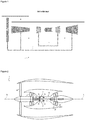
- la
figure 1 , déjà décrite, illustre de façon schématique une turbomachine connue de l'état de la technique, - la
figure 2 illustre de façon schématique un exemple de réalisation d'un ensemble pour turbomachine selon l'invention, - la
figure 3 illustre de façon schématique un exemple de réalisation d'une chambre de combustion isochore pour un mode de réalisation d'un ensemble pour turbomachine selon l'invention, et - la
figure 4 illustre schématiquement différentes étapes d'un exemple de mise en oeuvre d'un procédé de fonctionnement selon l'invention. - En référence aux figures, un ensemble pour turbomachine et un procédé de fonctionnement d'un ensemble pour turbomachine vont à présent être décrits.
- En référence à la
figure 2 , une turbomachine 1 comprend un compresseur 30 s'étendant selon un axe longitudinal X-X de la turbomachine 1. La turbomachine 1 comprend en outre une turbine 50 s'étendant également selon l'axe longitudinal X-X, la turbine 50 étant entraînée en rotation autour de l'axe longitudinal X-X par le compresseur 30. En outre, une chambre de combustion isobare 40 est agencée axialement entre le compresseur 30 et la turbine 50. La chambre de combustion isobare 40 est configurée pour être le siège d'une combustion isobare, c'est-à-dire à pression constante. Enfin, une chambre de combustion isochore 7 est agencée axialement entre le compresseur 30 et la chambre de combustion isobare 40. La chambre de combustion isochore 7 est configurée pour être le siège d'une combustion isochore, c'est-à-dire à volume constant. - De manière générale, la chambre de combustion isochore 7 est configurée pour redevoir un fluide en provenance du compresseur 30, la chambre de chambre de combustion isobare 40 est configurée pour recevoir un fluide refoulé depuis la chambre de combustion isochore 7, et la turbine 50 est configurée pour recevoir un fluide en provenance de la chambre de combustion isobare 40.
- Dans la présente demande, l'amont et l'aval sont définis par rapport au sens d'écoulement normal d'un fluide à travers la turbomachine 1 en fonctionnement. Par ailleurs, une direction axiale désigne une direction parallèle à l'axe longitudinal X-X, et une direction radiale est une direction perpendiculaire à cet axe longitudinal X-X, et passant par cet axe longitudinal X-X. Sauf précision contraire, interne (ou intérieur) et externe (ou extérieur), respectivement, sont utilisés en référence à une direction radiale de sorte que la partie ou la face interne (i.e. radialement interne) d'un élément est plus proche de l'axe longitudinal X-X, que la partie ou la face externe (i.e. radialement externe) du même élément.
- Comme également visible sur la
figure 2 , la turbomachine 1 peut comprendre une soufflante 10 et une turbine de soufflante 60 s'étendant chacune selon l'axe longitudinal X-X, la soufflante 10 étant entraînée en rotation autour de l'axe longitudinal X-X par la turbine de soufflante 60. Avantageusement, la turbine de soufflante 60 est disposée en aval de la turbine 50. De manière également avantageuse, la turbomachine 1 peut en outre comprendre un compresseur supplémentaire 20, s'étendant également selon l'axe longitudinal X-X, et disposé en aval de la soufflante 10 et en amont du compresseur 30. Ce compresseur supplémentaire 20 est également entraîné en rotation autour de l'axe longitudinal X-X par la turbine de soufflante 60. Dans un mode de réalisation, le compresseur supplémentaire 20 est un compresseur basse pression, le compresseur 30 est un compresseur haute pression, la turbine 50 est une turbine haute pression, et la turbine de soufflante 60 est une turbine basse pression. - En fonctionnement, du fluide admis par la soufflante 10, typiquement de l'air, est comprimé à travers les compresseurs 20, 30, puis subit une combustion à volume constant au sein de la chambre isochore 7 avant du subir une combustion à pression constante au sein de la chambre de combustion isobare 40, pour enfin être détendu dans les turbines 50, 60. Les turbines 50, 60 entraînent en rotation à la fois la soufflante 10 et les compresseurs 20, 30.
- En référence aux
figures 2 à 4 , la chambre de combustion isochore 7 comprend : - une soupape d'admission 70, ladite soupape d'admission 70 étant mobile entre :
- une position ouverte, dans laquelle la soupape d'admission 70 autorise l'admission d'un fluide en provenance du compresseur 30 vers la chambre de combustion isochore 7, et
- une position fermée, dans laquelle la soupape d'admission 70 empêche l'admission d'un fluide en provenance du compresseur 30 vers la chambre de combustion isochore 7, et
- une soupape de refoulement 72, ladite soupape de refoulement 72 étant mobile entre :
- une position ouverte, dans laquelle la soupape de refoulement 72 autorise le refoulement d'un fluide en provenance de la chambre de combustion isochore 7, et
- une position fermée, dans laquelle la soupape de refoulement 72 empêche le refoulement d'un fluide en provenance de la chambre de combustion isochore 7.
- Comme visible plus précisément sur les
figures 3 et4 , la chambre de combustion isochore 7 comprend avantageusement : - un conduit d'admission 74, configuré pour guider un fluide destiné à être admis au sein de la chambre de combustion isochore 7, par exemple en provenance du compresseur, et
- un conduit de refoulement 76, configuré pour guider un fluide refoulé depuis la chambre de combustion isochore 7, par exemple vers la chambre de combustion isobare 40.
- En référence aux
figures 3 et4 , dans un mode de réalisation, la turbomachine 1 comprend un système de commande d'admission 8 configuré pour commander un passage entre la position ouverte et la position fermée de la soupape d'admission 70. - Dans une variante avantageuse, le système de commande d'admission 8 comprend un premier électro-aimant 80, et un premier ressort de rappel 82. De manière privilégiée, le premier ressort de rappel 82 est configuré pour solliciter la soupape d'admission 70 vers la position ouverte. En outre, le premier électro-aimant 80 est configuré pour solliciter la soupape d'admission 70 vers la position fermée lorsque le premier électro-aimant 80 est alimenté en énergie électrique. De cette manière, en cas de panne du premier électro-aimant 80, la soupape d'admission 70 demeure en position ouverte.
- Toujours en référence aux
figures 3 et4 , dans un mode de réalisation, la turbomachine 1 comprend un système de commande de refoulement 9 configuré pour commander un passage entre la position ouverte et la position fermée de la soupape de refoulement 72. - Dans une variante avantageuse, le système de commande de refoulement 9 comprend un deuxième électro-aimant 90, et un deuxième ressort de rappel 92. De manière privilégiée, le deuxième ressort de rappel 92 est configuré pour solliciter la soupape de refoulement 72 vers la position ouverte. En outre, le deuxième électro-aimant 90 est configuré pour solliciter la soupape de refoulement 72 vers la position fermée lorsque le deuxième électro-aimant 90 est alimenté en énergie électrique. De cette manière, en cas de panne du deuxième électro-aimant 90, la soupape de refoulement 72 demeure en position ouverte.
- Dans un mode de réalisation, également illustré sur les
figures 3 et4 , la turbomachine 1 comprend un injecteur 78 configuré pour injecter du carburant à l'intérieur de la chambre de combustion isochore 7. Le carburant injecté est mélangé au fluide admis au sein de la chambre de combustion isochore 7 en vue de la combustion à volume constant, typiquement par auto-inflammation du mélange fluide-carburant. Comme visible sur lesfigures 3 et4 , dans une variante avantageuse, l'injecteur 78 est disposé plus proche de la soupape d'admission 70 que de la soupape de refoulement 72. En d'autres termes, la distance séparant la soupape d'admission 70 de l'injecteur 78 est inférieure à la distance séparant l'injecteur 78 de la soupape de refoulement 72. De cette manière, le mélange de carburant avec du fluide admis au sein de la chambre isochore 7 est favorisé, ce qui permet d'optimiser la combustion à volume constant. - Comme visible sur les
figures 2 à 4 , dans un mode de réalisation, la chambre de combustion isochore 7 s'étend selon l'axe longitudinal X-X. Avantageusement, l'injecteur 78 présente alors un axe Y-Y s'étendant selon une direction radiale à l'ace longitudinal X-X. Ceci permet d'optimiser la disposition de la chambre de combustion isochore 7 au sein de la turbomachine 1. - Dans un mode de réalisation visible sur la
figure 2 , la turbomachine 1 comprend une pluralité de chambres de combustion isochore 7 réparties circonférentiellement autour de l'axe longitudinal X-X. De cette manière, il est possible de contrôler l'augmentation de température du fluide reçu par la chambre de combustion isobare 40, mais également d'optimiser la gestion du débit de fluide en provenance du compresseur 30, qui est ensuite reçu par la chambre de combustion isobare 40. Ainsi, il est possible de s'affranchir de la présence d'une chambre de tranquillisation en amont de la chambre de combustion isobare 40. - En référence à la
figure 4 , un procédé de fonctionnement E d'un ensemble pour turbomachine 1 selon l'un quelconque des modes de réalisation précédemment décrits, comprend les étapes de : - admission E1 d'un fluide à l'intérieur de la chambre de combustion isochore 7,
- injection E2 de carburant à l'intérieur de la chambre de combustion isochore 7,
- combustion E3 du mélange formé par le fluide admis et le carburant injecté,
- refoulement E4 du fluide issu de la combustion du mélange hors de la chambre de combustion isochore 7, et
- balayage E5 de la chambre de combustion isochore 7.
- Comme visible sur la
figure 4 , dans un mode de mise en œuvre, durant les étapes d'injection E2 et de combustion E3, la soupape d'admission 70 et la soupape de refoulement 72 sont en position fermée. - Toujours en référence à la
figure 4 , dans un mode de mise en œuvre, durant l'étape de balayage E5, la soupape d'admission 70 et la soupape de refoulement 72 sont en position ouverte. - Ainsi, la combustion E3 se produit à volume constant, ce qui entraîne une hausse de pression et de température du mélange. Lors du refoulement E4, le mélange est à haute température et haute pression au moment d'être reçu par la chambre de combustion isochore 40. La pression et la température diminue alors progressivement au sein de la chambre de combustion isochore 7. Puis, une fois que la pression à l'intérieur de la chambre de combustion isochore 40 est descendue en-dessous du niveau de la pression de fluide en aval du compresseur 30, le passage de la soupape d'admission 70 en position ouverte permet de remplacer le mélange brûlé par du fluide frais au sein de la chambre de combustion isochore 7.
- Dans un mode de mise en œuvre où la turbomachine 1 comprend une pluralité de chambres de combustion isochore 7, chaque chambre de combustion isochore 7 peut fonctionner de manière déphasée par rapport aux autres chambres de combustion isochore 7. Plus précisément, chaque chambre de combustion isochore 7 met en œuvre une étape E1, E2, E3, E4, E5 de fonctionnement qui est différente des étapes E1, E2, E3, E4, E5 de fonctionnement mises en œuvre par les autres chambres de combustion isochore 7.
- Dans un mode de mise en œuvre, il est nécessaire de s'assurer que le mélange refoulé de la chambre de combustion isochore 7 comprenne un excès de fluide par rapport aux gaz brûlés afin de s'assurer qu'une combustion peut être réalisée dans la chambre de combustion isobare 40.
- Pour ce faire, dans une première variante de mise en œuvre, la quantité de carburant injecté lors de l'injection E2 est inférieure à la quantité stœchiométrique de carburant nécessaire à la combustion de la totalité du fluide admis au sein de la chambre de combustion isochore 7. Dans cette première variante de mise en œuvre, la quantité de carburant injectée est néanmoins suffisante pour que, dans les conditions de température et de pression au sein de la chambre de combustion isochore 7, le mélange puisse s'auto-enflammée, sans qu'il ne soit nécessaire d'employer une bougie. Dans ce cas, il est également possible de limiter le temps de réalisation de l'étape de balayage E5 afin de s'assurer qu'une partie des gaz brûlés du mélange reste emprisonnés dans la chambre de combustion isochore 7 afin de faciliter l'auto-inflammation le cas échéant.
- Dans une seconde variante de mise en œuvre pour assurer l'excès de fluide, l'étape de balayage E5 est prolongée suffisamment pour qu'un excès de fluide puisse parvenir au sein de la chambre de combustion isobare 40.
- Dans un mode de mise en œuvre, le conduit d'admission 74 et le conduit de refoulement 76 jouent, avec la chambre de combustion isobare 40, le rôle de volume tampon pour le fonctionnement de la chambre de combustion isochore 7.
- En tout état de cause, aucune puissance mécanique n'est récupérée par la turbomachine 1 suite à la combustion à volume constant au sein de la chambre de combustion isochore 7.
Claims (14)
- Ensemble pour turbomachine (1) comprenant :un compresseur (30),une chambre de combustion isochore (7), ladite chambre de combustion isochore (7) comprenant :une soupape d'admission (70), ladite soupape d'admission (70) étant mobile entre :une position ouverte, dans laquelle la soupape d'admission (70) autorise l'admission d'un fluide en provenance du compresseur (30) vers la chambre de combustion isochore (7), etune position fermée, dans laquelle la soupape d'admission (70) empêche l'admission d'un fluide en provenance du compresseur (30) vers la chambre de combustion isochore (7), etune soupape de refoulement (72), ladite soupape de refoulement (72) étant mobile entre :une position ouverte, dans laquelle la soupape de refoulement (72) autorise le refoulement d'un fluide en provenance de la chambre de combustion isochore (7), etune position fermée, dans laquelle la soupape de refoulement (72) empêche le refoulement d'un fluide en provenance de la chambre de combustion isochore (7),une chambre de combustion isobare (40) configurée pour recevoir un fluide refoulé depuis la chambre de combustion isochore (7), etune turbine (50) configurée pour recevoir un fluide en provenance de la chambre de combustion isobare (40).
- Ensemble selon la revendication 1, comprenant un système de commande d'admission (8) configuré pour commander un passage entre la position ouverte et la position fermée de la soupape d'admission (70), le système de commande d'admission (8) comprenant un premier électro-aimant (80) et un premier ressort de rappel (82).
- Ensemble selon la revendication 2, dans lequel le premier ressort de rappel (82) est configuré pour solliciter la soupape d'admission (70) vers la position ouverte.
- Ensemble selon l'une des revendications 2 et 3, dans lequel le premier électro-aimant (80) est configuré pour solliciter la soupape d'admission vers la position fermée lorsque le premier électro-aimant (80) est alimenté en énergie électrique.
- Ensemble selon l'une des revendications 1 à 4, comprenant un système de commande de refoulement (9) configuré pour commander un passage entre la position ouverte et la position fermée de la soupape de refoulement (72), le système de commande de refoulement comprenant (9) un deuxième électro-aimant (90) et un deuxième ressort de rappel (92).
- Ensemble selon la revendication 5, dans lequel le deuxième ressort de rappel (92) est configuré pour solliciter la soupape de refoulement (72) vers la position ouverte.
- Ensemble selon l'une des revendications 5 et 6, dans lequel le deuxième électro-aimant (90) est configuré pour solliciter la soupape de refoulement (72) vers la position fermée lorsque le deuxième électro-aimant (90) est alimenté en énergie électrique.
- Ensemble selon l'une des revendications 1 à 7, comprenant un injecteur (78) configuré pour injecter du carburant à l'intérieur de la chambre de combustion isochore (7).
- Ensemble selon la revendication 8, dans lequel l'injecteur (78) est disposé plus proche de la soupape d'admission (70) que de la soupape de refoulement (72).
- Ensemble selon l'une des revendications 8 et 9, dans lequel la chambre de combustion isochore (7) s'étend selon un axe longitudinal (X-X) de la turbomachine (1), l'injecteur (78) présentant un axe (Y-Y) s'étendant selon une direction radiale à l'axe longitudinal (X-X).
- Procédé de fonctionnement (E) d'un ensemble selon l'une des revendications 1 à 10, comprenant les étapes de :admission (E1) d'un fluide à l'intérieur de la chambre de combustion isochore (7),injection (E2) de carburant à l'intérieur de la chambre de combustion isochore (7),combustion (E3) du mélange formé par le fluide admis et le carburant injecté,refoulement (E4) du fluide issu de la combustion du mélange hors de la chambre de combustion isochore (7), etbalayage (E5) de la chambre de combustion isochore (7).
- Procédé de fonctionnement (E) selon la revendication 11, dans lequel, durant les étapes d'injection (E2) et de combustion (E3), la soupape d'admission (70) et la soupape de refoulement (72) sont en position fermée.
- Procédé de fonctionnement (E) selon l'une des revendications 11 et 12, dans lequel, durant l'étape de balayage (E5), la soupape d'admission (70) et la soupape de refoulement (72) sont en position ouverte.
- Turbomachine comprenant un ensemble selon l'une des revendications 1 à 10.
Applications Claiming Priority (1)
| Application Number | Priority Date | Filing Date | Title |
|---|---|---|---|
| FR1900514A FR3091899B1 (fr) | 2019-01-22 | 2019-01-22 | Ensemble pour turbomachine |
Publications (2)
| Publication Number | Publication Date |
|---|---|
| EP3686411A1 true EP3686411A1 (fr) | 2020-07-29 |
| EP3686411B1 EP3686411B1 (fr) | 2021-12-22 |
Family
ID=67001961
Family Applications (1)
| Application Number | Title | Priority Date | Filing Date |
|---|---|---|---|
| EP20305049.7A Active EP3686411B1 (fr) | 2019-01-22 | 2020-01-22 | Ensemble pour turbomachine |
Country Status (4)
| Country | Link |
|---|---|
| US (1) | US11193424B2 (fr) |
| EP (1) | EP3686411B1 (fr) |
| CN (1) | CN111456851B (fr) |
| FR (1) | FR3091899B1 (fr) |
Families Citing this family (1)
| Publication number | Priority date | Publication date | Assignee | Title |
|---|---|---|---|---|
| US12392282B2 (en) | 2023-03-28 | 2025-08-19 | Pratt & Whitney Canada Corp. | Constant volume combustor for gas turbine engine |
Citations (3)
| Publication number | Priority date | Publication date | Assignee | Title |
|---|---|---|---|---|
| GB374648A (en) * | 1930-06-30 | 1932-06-16 | Hans Holzwarth | Improvements in and relating to methods of operating cylindrical elongated explosionchambers, in particular for internal combustion turbines |
| FR2829528A1 (fr) * | 2001-09-07 | 2003-03-14 | Bernard Gilbert Macarez | Pulsomoteur-turbomoteur a impulsion-turbine a gaz a chambre de combustion impulsionnelle et a detente de bouffees |
| WO2016198792A1 (fr) * | 2015-06-11 | 2016-12-15 | Safran Helicopter Engines | Module de chambre de combustion cvc de turbomachine comportant une préchambre de combustion |
Family Cites Families (3)
| Publication number | Priority date | Publication date | Assignee | Title |
|---|---|---|---|---|
| US2791884A (en) * | 1951-12-24 | 1957-05-14 | Schilling Estate Company | Multi-stage explosion turbine plant for generating driving gases |
| DE4331081A1 (de) * | 1993-09-13 | 1995-03-16 | Abb Management Ag | Verfahren zum Betrieb einer Gasturbinenanlage |
| FR3032781B1 (fr) * | 2015-02-17 | 2018-07-06 | Safran Helicopter Engines | Systeme de combustion a volume constant pour turbomachine de moteur d'aeronef |
-
2019
- 2019-01-22 FR FR1900514A patent/FR3091899B1/fr not_active Expired - Fee Related
-
2020
- 2020-01-21 US US16/748,079 patent/US11193424B2/en active Active
- 2020-01-22 CN CN202010074357.XA patent/CN111456851B/zh active Active
- 2020-01-22 EP EP20305049.7A patent/EP3686411B1/fr active Active
Patent Citations (3)
| Publication number | Priority date | Publication date | Assignee | Title |
|---|---|---|---|---|
| GB374648A (en) * | 1930-06-30 | 1932-06-16 | Hans Holzwarth | Improvements in and relating to methods of operating cylindrical elongated explosionchambers, in particular for internal combustion turbines |
| FR2829528A1 (fr) * | 2001-09-07 | 2003-03-14 | Bernard Gilbert Macarez | Pulsomoteur-turbomoteur a impulsion-turbine a gaz a chambre de combustion impulsionnelle et a detente de bouffees |
| WO2016198792A1 (fr) * | 2015-06-11 | 2016-12-15 | Safran Helicopter Engines | Module de chambre de combustion cvc de turbomachine comportant une préchambre de combustion |
Non-Patent Citations (1)
| Title |
|---|
| GEO A RICHARDS: "New Developments in Combustion Technology Part II: Step change in efficiency", 24 June 2014 (2014-06-24), Princeton, XP055634505, Retrieved from the Internet <URL:https://cefrc.princeton.edu/sites/cefrc/files/Files/2014%20Lecture%20Notes/Richards/NewDevelopmentsGeoRichards-Part-2of3-PGAIN_-2014.pdf> [retrieved on 20191022] * |
Also Published As
| Publication number | Publication date |
|---|---|
| FR3091899A1 (fr) | 2020-07-24 |
| US11193424B2 (en) | 2021-12-07 |
| US20200277899A1 (en) | 2020-09-03 |
| CN111456851A (zh) | 2020-07-28 |
| EP3686411B1 (fr) | 2021-12-22 |
| CN111456851B (zh) | 2023-02-28 |
| FR3091899B1 (fr) | 2020-12-25 |
Similar Documents
| Publication | Publication Date | Title |
|---|---|---|
| CA2758078C (fr) | Prelevement d'air avec filtre inertiel dans le rotor tandem d'un compresseur | |
| CA2639356C (fr) | Chambre de combustion de turbomachine a circulation helicoidale de l'air | |
| EP3286418B1 (fr) | Méthode de contrôle de la quantité d'air introduit à l'admission d'un moteur à combustion interne suralimenté | |
| EP3455481B1 (fr) | Methode de controle de la quantite d'air introduit a l'admission d'un moteur a combustion interne suralimente par un turbocompresseur a simple entree | |
| WO2017085406A1 (fr) | Ensemble propulsif comprenant un moteur principal et un moteur auxiliaire | |
| FR2990996A1 (fr) | Moteur a combustion interne muni d'un systeme de recirculation des gaz d'echappement (egr) et procede de commande de la recirculation des gaz associe | |
| EP3686411B1 (fr) | Ensemble pour turbomachine | |
| WO2021191528A1 (fr) | Turbomachine à double flux comprenant un dispositif de régulation du débit de fluide de refroidissement | |
| EP1861598A2 (fr) | Dispositif d'acceleration d'un groupe de turbocompression aux bas regimes d'un moteur alternatif et moteur alternatif comportant un tel dispositif | |
| EP0090122A2 (fr) | Dispositif de régulation de l'alimentation d'un moteur à combustion interne | |
| EP1908937A1 (fr) | Moteur a combustion interne suralimenté et procédé de suralimentation | |
| EP1694953A1 (fr) | Procede de commande pour la regeneration d'un filtre a particules | |
| EP1524425B1 (fr) | Procédé de commande pour la régénération d'un filtre à particules | |
| EP2986833A1 (fr) | Procède d'amélioration du rendement énergétique d'un système d'entraînement | |
| EP4423386B1 (fr) | Pompe à haute pression pour moteur à combustion interne de véhicule automobile | |
| WO2024209168A1 (fr) | Architecture d'un moteur thermique à dihydrogène et procédé de caractérisations des paramètres géométriques et fonctionnels dudit moteur | |
| EP3330520B1 (fr) | Procédé et système de protection d'une roue d'un compresseur d'un turbocompresseur | |
| FR2797306A1 (fr) | Moteur turbocompresse perfectionne | |
| EP4144983A1 (fr) | Pompe à haute pression d'un système de carburation à injection directe de carburant liquide d'un moteur à combustion interne à bicarburation d'un véhicule automobile | |
| FR2914366A1 (fr) | Procede de controle du fonctionnement d'un moteur a combustion interne en mode de combustion a autoallumage controle et moteur utilisant un tel procede | |
| EP3601770B1 (fr) | Procede de controle d'un moteur a allumage commande suralimente avec recirculation partielle des gaz d'echappement, et dispositif de motorisation associe | |
| FR3067061B1 (fr) | Systeme d'alimentation d'un moteur a combustion interne | |
| FR3043728A1 (fr) | Ensemble propulsif comprenant un moteur principal et un moteur auxiliaire | |
| FR3087837A1 (fr) | Ensemble pour turbomachine | |
| FR2904051A1 (fr) | Procede de regeneration d'un filtre a particules |
Legal Events
| Date | Code | Title | Description |
|---|---|---|---|
| PUAI | Public reference made under article 153(3) epc to a published international application that has entered the european phase |
Free format text: ORIGINAL CODE: 0009012 |
|
| STAA | Information on the status of an ep patent application or granted ep patent |
Free format text: STATUS: THE APPLICATION HAS BEEN PUBLISHED |
|
| AK | Designated contracting states |
Kind code of ref document: A1 Designated state(s): AL AT BE BG CH CY CZ DE DK EE ES FI FR GB GR HR HU IE IS IT LI LT LU LV MC MK MT NL NO PL PT RO RS SE SI SK SM TR |
|
| AX | Request for extension of the european patent |
Extension state: BA ME |
|
| STAA | Information on the status of an ep patent application or granted ep patent |
Free format text: STATUS: REQUEST FOR EXAMINATION WAS MADE |
|
| 17P | Request for examination filed |
Effective date: 20210122 |
|
| RBV | Designated contracting states (corrected) |
Designated state(s): AL AT BE BG CH CY CZ DE DK EE ES FI FR GB GR HR HU IE IS IT LI LT LU LV MC MK MT NL NO PL PT RO RS SE SI SK SM TR |
|
| GRAP | Despatch of communication of intention to grant a patent |
Free format text: ORIGINAL CODE: EPIDOSNIGR1 |
|
| STAA | Information on the status of an ep patent application or granted ep patent |
Free format text: STATUS: GRANT OF PATENT IS INTENDED |
|
| RIC1 | Information provided on ipc code assigned before grant |
Ipc: F23R 7/00 20060101ALI20210831BHEP Ipc: F23R 3/34 20060101ALI20210831BHEP Ipc: F02C 5/12 20060101ALI20210831BHEP Ipc: F02C 5/02 20060101AFI20210831BHEP |
|
| INTG | Intention to grant announced |
Effective date: 20210923 |
|
| GRAS | Grant fee paid |
Free format text: ORIGINAL CODE: EPIDOSNIGR3 |
|
| GRAA | (expected) grant |
Free format text: ORIGINAL CODE: 0009210 |
|
| STAA | Information on the status of an ep patent application or granted ep patent |
Free format text: STATUS: THE PATENT HAS BEEN GRANTED |
|
| AK | Designated contracting states |
Kind code of ref document: B1 Designated state(s): AL AT BE BG CH CY CZ DE DK EE ES FI FR GB GR HR HU IE IS IT LI LT LU LV MC MK MT NL NO PL PT RO RS SE SI SK SM TR |
|
| REG | Reference to a national code |
Ref country code: GB Ref legal event code: FG4D Free format text: NOT ENGLISH |
|
| REG | Reference to a national code |
Ref country code: CH Ref legal event code: EP |
|
| REG | Reference to a national code |
Ref country code: DE Ref legal event code: R096 Ref document number: 602020001385 Country of ref document: DE |
|
| REG | Reference to a national code |
Ref country code: AT Ref legal event code: REF Ref document number: 1457228 Country of ref document: AT Kind code of ref document: T Effective date: 20220115 |
|
| REG | Reference to a national code |
Ref country code: IE Ref legal event code: FG4D Free format text: LANGUAGE OF EP DOCUMENT: FRENCH |
|
| REG | Reference to a national code |
Ref country code: SE Ref legal event code: TRGR |
|
| REG | Reference to a national code |
Ref country code: LT Ref legal event code: MG9D |
|
| PG25 | Lapsed in a contracting state [announced via postgrant information from national office to epo] |
Ref country code: RS Free format text: LAPSE BECAUSE OF FAILURE TO SUBMIT A TRANSLATION OF THE DESCRIPTION OR TO PAY THE FEE WITHIN THE PRESCRIBED TIME-LIMIT Effective date: 20211222 Ref country code: LT Free format text: LAPSE BECAUSE OF FAILURE TO SUBMIT A TRANSLATION OF THE DESCRIPTION OR TO PAY THE FEE WITHIN THE PRESCRIBED TIME-LIMIT Effective date: 20211222 Ref country code: FI Free format text: LAPSE BECAUSE OF FAILURE TO SUBMIT A TRANSLATION OF THE DESCRIPTION OR TO PAY THE FEE WITHIN THE PRESCRIBED TIME-LIMIT Effective date: 20211222 Ref country code: BG Free format text: LAPSE BECAUSE OF FAILURE TO SUBMIT A TRANSLATION OF THE DESCRIPTION OR TO PAY THE FEE WITHIN THE PRESCRIBED TIME-LIMIT Effective date: 20220322 |
|
| REG | Reference to a national code |
Ref country code: NL Ref legal event code: MP Effective date: 20211222 |
|
| REG | Reference to a national code |
Ref country code: AT Ref legal event code: MK05 Ref document number: 1457228 Country of ref document: AT Kind code of ref document: T Effective date: 20211222 |
|
| PG25 | Lapsed in a contracting state [announced via postgrant information from national office to epo] |
Ref country code: NO Free format text: LAPSE BECAUSE OF FAILURE TO SUBMIT A TRANSLATION OF THE DESCRIPTION OR TO PAY THE FEE WITHIN THE PRESCRIBED TIME-LIMIT Effective date: 20220322 Ref country code: LV Free format text: LAPSE BECAUSE OF FAILURE TO SUBMIT A TRANSLATION OF THE DESCRIPTION OR TO PAY THE FEE WITHIN THE PRESCRIBED TIME-LIMIT Effective date: 20211222 Ref country code: HR Free format text: LAPSE BECAUSE OF FAILURE TO SUBMIT A TRANSLATION OF THE DESCRIPTION OR TO PAY THE FEE WITHIN THE PRESCRIBED TIME-LIMIT Effective date: 20211222 Ref country code: GR Free format text: LAPSE BECAUSE OF FAILURE TO SUBMIT A TRANSLATION OF THE DESCRIPTION OR TO PAY THE FEE WITHIN THE PRESCRIBED TIME-LIMIT Effective date: 20220323 |
|
| PG25 | Lapsed in a contracting state [announced via postgrant information from national office to epo] |
Ref country code: NL Free format text: LAPSE BECAUSE OF FAILURE TO SUBMIT A TRANSLATION OF THE DESCRIPTION OR TO PAY THE FEE WITHIN THE PRESCRIBED TIME-LIMIT Effective date: 20211222 |
|
| PG25 | Lapsed in a contracting state [announced via postgrant information from national office to epo] |
Ref country code: SM Free format text: LAPSE BECAUSE OF FAILURE TO SUBMIT A TRANSLATION OF THE DESCRIPTION OR TO PAY THE FEE WITHIN THE PRESCRIBED TIME-LIMIT Effective date: 20211222 Ref country code: SK Free format text: LAPSE BECAUSE OF FAILURE TO SUBMIT A TRANSLATION OF THE DESCRIPTION OR TO PAY THE FEE WITHIN THE PRESCRIBED TIME-LIMIT Effective date: 20211222 Ref country code: RO Free format text: LAPSE BECAUSE OF FAILURE TO SUBMIT A TRANSLATION OF THE DESCRIPTION OR TO PAY THE FEE WITHIN THE PRESCRIBED TIME-LIMIT Effective date: 20211222 Ref country code: PT Free format text: LAPSE BECAUSE OF FAILURE TO SUBMIT A TRANSLATION OF THE DESCRIPTION OR TO PAY THE FEE WITHIN THE PRESCRIBED TIME-LIMIT Effective date: 20220422 Ref country code: ES Free format text: LAPSE BECAUSE OF FAILURE TO SUBMIT A TRANSLATION OF THE DESCRIPTION OR TO PAY THE FEE WITHIN THE PRESCRIBED TIME-LIMIT Effective date: 20211222 Ref country code: EE Free format text: LAPSE BECAUSE OF FAILURE TO SUBMIT A TRANSLATION OF THE DESCRIPTION OR TO PAY THE FEE WITHIN THE PRESCRIBED TIME-LIMIT Effective date: 20211222 Ref country code: CZ Free format text: LAPSE BECAUSE OF FAILURE TO SUBMIT A TRANSLATION OF THE DESCRIPTION OR TO PAY THE FEE WITHIN THE PRESCRIBED TIME-LIMIT Effective date: 20211222 |
|
| PG25 | Lapsed in a contracting state [announced via postgrant information from national office to epo] |
Ref country code: PL Free format text: LAPSE BECAUSE OF FAILURE TO SUBMIT A TRANSLATION OF THE DESCRIPTION OR TO PAY THE FEE WITHIN THE PRESCRIBED TIME-LIMIT Effective date: 20211222 Ref country code: AT Free format text: LAPSE BECAUSE OF FAILURE TO SUBMIT A TRANSLATION OF THE DESCRIPTION OR TO PAY THE FEE WITHIN THE PRESCRIBED TIME-LIMIT Effective date: 20211222 |
|
| REG | Reference to a national code |
Ref country code: DE Ref legal event code: R097 Ref document number: 602020001385 Country of ref document: DE |
|
| PG25 | Lapsed in a contracting state [announced via postgrant information from national office to epo] |
Ref country code: MC Free format text: LAPSE BECAUSE OF FAILURE TO SUBMIT A TRANSLATION OF THE DESCRIPTION OR TO PAY THE FEE WITHIN THE PRESCRIBED TIME-LIMIT Effective date: 20211222 Ref country code: IS Free format text: LAPSE BECAUSE OF FAILURE TO SUBMIT A TRANSLATION OF THE DESCRIPTION OR TO PAY THE FEE WITHIN THE PRESCRIBED TIME-LIMIT Effective date: 20220422 |
|
| REG | Reference to a national code |
Ref country code: BE Ref legal event code: MM Effective date: 20220131 |
|
| PLBE | No opposition filed within time limit |
Free format text: ORIGINAL CODE: 0009261 |
|
| STAA | Information on the status of an ep patent application or granted ep patent |
Free format text: STATUS: NO OPPOSITION FILED WITHIN TIME LIMIT |
|
| PG25 | Lapsed in a contracting state [announced via postgrant information from national office to epo] |
Ref country code: LU Free format text: LAPSE BECAUSE OF NON-PAYMENT OF DUE FEES Effective date: 20220122 Ref country code: DK Free format text: LAPSE BECAUSE OF FAILURE TO SUBMIT A TRANSLATION OF THE DESCRIPTION OR TO PAY THE FEE WITHIN THE PRESCRIBED TIME-LIMIT Effective date: 20211222 Ref country code: AL Free format text: LAPSE BECAUSE OF FAILURE TO SUBMIT A TRANSLATION OF THE DESCRIPTION OR TO PAY THE FEE WITHIN THE PRESCRIBED TIME-LIMIT Effective date: 20211222 |
|
| 26N | No opposition filed |
Effective date: 20220923 |
|
| PG25 | Lapsed in a contracting state [announced via postgrant information from national office to epo] |
Ref country code: BE Free format text: LAPSE BECAUSE OF NON-PAYMENT OF DUE FEES Effective date: 20220131 |
|
| PG25 | Lapsed in a contracting state [announced via postgrant information from national office to epo] |
Ref country code: IE Free format text: LAPSE BECAUSE OF NON-PAYMENT OF DUE FEES Effective date: 20220122 |
|
| PG25 | Lapsed in a contracting state [announced via postgrant information from national office to epo] |
Ref country code: SI Free format text: LAPSE BECAUSE OF FAILURE TO SUBMIT A TRANSLATION OF THE DESCRIPTION OR TO PAY THE FEE WITHIN THE PRESCRIBED TIME-LIMIT Effective date: 20211222 |
|
| REG | Reference to a national code |
Ref country code: CH Ref legal event code: PL |
|
| PG25 | Lapsed in a contracting state [announced via postgrant information from national office to epo] |
Ref country code: LI Free format text: LAPSE BECAUSE OF NON-PAYMENT OF DUE FEES Effective date: 20230131 Ref country code: CH Free format text: LAPSE BECAUSE OF NON-PAYMENT OF DUE FEES Effective date: 20230131 |
|
| PG25 | Lapsed in a contracting state [announced via postgrant information from national office to epo] |
Ref country code: MK Free format text: LAPSE BECAUSE OF FAILURE TO SUBMIT A TRANSLATION OF THE DESCRIPTION OR TO PAY THE FEE WITHIN THE PRESCRIBED TIME-LIMIT Effective date: 20211222 Ref country code: CY Free format text: LAPSE BECAUSE OF FAILURE TO SUBMIT A TRANSLATION OF THE DESCRIPTION OR TO PAY THE FEE WITHIN THE PRESCRIBED TIME-LIMIT Effective date: 20211222 |
|
| PG25 | Lapsed in a contracting state [announced via postgrant information from national office to epo] |
Ref country code: HU Free format text: LAPSE BECAUSE OF FAILURE TO SUBMIT A TRANSLATION OF THE DESCRIPTION OR TO PAY THE FEE WITHIN THE PRESCRIBED TIME-LIMIT; INVALID AB INITIO Effective date: 20200122 |
|
| PG25 | Lapsed in a contracting state [announced via postgrant information from national office to epo] |
Ref country code: MT Free format text: LAPSE BECAUSE OF FAILURE TO SUBMIT A TRANSLATION OF THE DESCRIPTION OR TO PAY THE FEE WITHIN THE PRESCRIBED TIME-LIMIT Effective date: 20211222 |
|
| PG25 | Lapsed in a contracting state [announced via postgrant information from national office to epo] |
Ref country code: TR Free format text: LAPSE BECAUSE OF FAILURE TO SUBMIT A TRANSLATION OF THE DESCRIPTION OR TO PAY THE FEE WITHIN THE PRESCRIBED TIME-LIMIT Effective date: 20211222 |
|
| PGFP | Annual fee paid to national office [announced via postgrant information from national office to epo] |
Ref country code: SE Payment date: 20260121 Year of fee payment: 7 |
|
| PGFP | Annual fee paid to national office [announced via postgrant information from national office to epo] |
Ref country code: GB Payment date: 20260122 Year of fee payment: 7 |
|
| PGFP | Annual fee paid to national office [announced via postgrant information from national office to epo] |
Ref country code: DE Payment date: 20260120 Year of fee payment: 7 |
|
| PGFP | Annual fee paid to national office [announced via postgrant information from national office to epo] |
Ref country code: IT Payment date: 20260130 Year of fee payment: 7 |
|
| PGFP | Annual fee paid to national office [announced via postgrant information from national office to epo] |
Ref country code: FR Payment date: 20260128 Year of fee payment: 7 |