EP3686270B1 - Heating mechanism for biochemical reaction device - Google Patents
Heating mechanism for biochemical reaction device Download PDFInfo
- Publication number
- EP3686270B1 EP3686270B1 EP17926241.5A EP17926241A EP3686270B1 EP 3686270 B1 EP3686270 B1 EP 3686270B1 EP 17926241 A EP17926241 A EP 17926241A EP 3686270 B1 EP3686270 B1 EP 3686270B1
- Authority
- EP
- European Patent Office
- Prior art keywords
- heat
- conducting
- heating mechanism
- reaction
- conducting block
- Prior art date
- Legal status (The legal status is an assumption and is not a legal conclusion. Google has not performed a legal analysis and makes no representation as to the accuracy of the status listed.)
- Active
Links
Images





Classifications
-
- B—PERFORMING OPERATIONS; TRANSPORTING
- B01—PHYSICAL OR CHEMICAL PROCESSES OR APPARATUS IN GENERAL
- B01L—CHEMICAL OR PHYSICAL LABORATORY APPARATUS FOR GENERAL USE
- B01L7/00—Heating or cooling apparatus; Heat insulating devices
-
- B—PERFORMING OPERATIONS; TRANSPORTING
- B01—PHYSICAL OR CHEMICAL PROCESSES OR APPARATUS IN GENERAL
- B01L—CHEMICAL OR PHYSICAL LABORATORY APPARATUS FOR GENERAL USE
- B01L7/00—Heating or cooling apparatus; Heat insulating devices
- B01L7/52—Heating or cooling apparatus; Heat insulating devices with provision for submitting samples to a predetermined sequence of different temperatures, e.g. for treating nucleic acid samples
-
- B—PERFORMING OPERATIONS; TRANSPORTING
- B01—PHYSICAL OR CHEMICAL PROCESSES OR APPARATUS IN GENERAL
- B01L—CHEMICAL OR PHYSICAL LABORATORY APPARATUS FOR GENERAL USE
- B01L9/00—Supporting devices; Holding devices
- B01L9/50—Clamping means, e.g. tongs
-
- C—CHEMISTRY; METALLURGY
- C12—BIOCHEMISTRY; BEER; SPIRITS; WINE; VINEGAR; MICROBIOLOGY; ENZYMOLOGY; MUTATION OR GENETIC ENGINEERING
- C12M—APPARATUS FOR ENZYMOLOGY OR MICROBIOLOGY; APPARATUS FOR CULTURING MICROORGANISMS FOR PRODUCING BIOMASS, FOR GROWING CELLS OR FOR OBTAINING FERMENTATION OR METABOLIC PRODUCTS, i.e. BIOREACTORS OR FERMENTERS
- C12M1/00—Apparatus for enzymology or microbiology
- C12M1/36—Apparatus for enzymology or microbiology including condition or time responsive control, e.g. automatically controlled fermentors
- C12M1/38—Temperature-responsive control
-
- B—PERFORMING OPERATIONS; TRANSPORTING
- B01—PHYSICAL OR CHEMICAL PROCESSES OR APPARATUS IN GENERAL
- B01L—CHEMICAL OR PHYSICAL LABORATORY APPARATUS FOR GENERAL USE
- B01L2200/00—Solutions for specific problems relating to chemical or physical laboratory apparatus
- B01L2200/02—Adapting objects or devices to another
- B01L2200/023—Adapting objects or devices to another adapted for different sizes of tubes, tips or container
-
- B—PERFORMING OPERATIONS; TRANSPORTING
- B01—PHYSICAL OR CHEMICAL PROCESSES OR APPARATUS IN GENERAL
- B01L—CHEMICAL OR PHYSICAL LABORATORY APPARATUS FOR GENERAL USE
- B01L2200/00—Solutions for specific problems relating to chemical or physical laboratory apparatus
- B01L2200/02—Adapting objects or devices to another
- B01L2200/028—Modular arrangements
-
- B—PERFORMING OPERATIONS; TRANSPORTING
- B01—PHYSICAL OR CHEMICAL PROCESSES OR APPARATUS IN GENERAL
- B01L—CHEMICAL OR PHYSICAL LABORATORY APPARATUS FOR GENERAL USE
- B01L2300/00—Additional constructional details
- B01L2300/08—Geometry, shape and general structure
- B01L2300/0832—Geometry, shape and general structure cylindrical, tube shaped
-
- B—PERFORMING OPERATIONS; TRANSPORTING
- B01—PHYSICAL OR CHEMICAL PROCESSES OR APPARATUS IN GENERAL
- B01L—CHEMICAL OR PHYSICAL LABORATORY APPARATUS FOR GENERAL USE
- B01L2300/00—Additional constructional details
- B01L2300/18—Means for temperature control
- B01L2300/1805—Conductive heating, heat from thermostatted solids is conducted to receptacles, e.g. heating plates, blocks
Definitions
- the present invention relates generally to a heating device, and more particularly to a heating mechanism for heating or regulating the temperature of a reaction tube in a biochemical reaction device.
- Biochemical reaction devices such as polymerase chain reaction (PCR) devices, must undergo loops of three reaction steps, including denaturation, annealing, and extension, when performing nucleic acid amplification reactions.
- Each reaction step has a preset optimal reaction temperature.
- the denaturation reaction is generally set between about 90 and 95°C
- the annealing reaction is set between about 35 to 65°C depending on the different primers
- the extension reaction is set at a temperature of about 72°C suitable for the polymerase reaction.
- the aforementioned reaction temperatures are closely correlated to the results of nucleic acid amplification, especially in the annealing reaction stage. If it is used to detect a target nucleic acid, the positive or negative determination is further affected by the reaction conditions. Therefore, accurate control of the reaction temperature is one of the important requirements of the device.
- the reaction tubes containing the reaction solution are respectively placed into a heating module provided with a plurality of holes, thereby achieving the purpose of controlling the temperature of the reaction tubes through a heat conduction by the contact between an inner wall of the heating module and the reaction tubes.
- a heating module provided with a plurality of holes
- the numerous types and specifications of the reaction tube will cause uneven or insufficient contact between the outer wall of the reaction tube and the hole of the heating module, this may result in the uneven temperature of the solution in the reaction tube or the solution may fail to reach the preset temperature, thereby lowering efficiency of the reaction or yield of the amplified product.
- the reaction tubes are used to detect a specific target nucleic acid sequence, the accuracy of the detection result is also affected.
- mineral oil may be added to the hole to fill the gap between the reaction tube and the hole to improve heat transfer efficiency.
- the addition of mineral oil may easily cause sample contamination and cause mechanical cleaning and maintenance difficulties. More importantly, the mineral oil will also absorb and dissipate heat. After adding different volumes of mineral oil to the holes, there is also often a difference between the actual temperature and the preset temperature among the holes or even in the whole heating module.
- the heating module is bulky and thus requires a longer time to heat and dissipate heat, and therefore the required overall reaction time increases.
- EP 1347833 B1 discloses a device for processing a biological sample that includes a processing unit having at least one opening to receive a sample vessel and a plurality of processing stations positioned along the opening.
- the processing stations each have a compression member adapted to compress the sample vessel within the opening and thereby move the sample within the sample vessel among the processing stations.
- An energy transfer element can be coupled to one or more of the processing stations for transferring thermal energy to the sample at a processing station.
- EP 1347833 B1 only provides a stationary member that can indirectly transfer heat to the sample vessel clamped by the compression member, and thus a heating efficiency needs to be improved.
- the present invention provides a heating mechanism for a biochemical reaction device capable of conveniently placing a reaction container to be heated therein and capable of easily limiting the reaction container in a position.
- the reaction container can be easily held and fixed in the heating mechanism by applying a thrust thereto but without deliberately adjusting the placement position of the reaction container, and then can be heated by heat conduction due to the clamping by the heat-conducting blocks thereon.
- the present invention also provides a heating mechanism capable of precisely regulating the temperature of a biochemical reaction.
- the heat-conducting blocks can be in close and direct contact with the reaction container for heat conduction, so that the solution in the reaction container can assuredly reach the preset temperature.
- the heating conditions of the respective reaction containers are consistent with each other, so that the reaction can be more efficiently performed with fast heat transfer, and the reproducibility and accuracy of the reaction result can also be improved.
- the present invention also provides a heating mechanism that can reduce the volume of a biochemical reaction device. According to the small and compact heating mechanism of the present invention, the same objective of the heat conduction can be achieved, but the required volume and space for the overall device can be reduced. Also, because of the compact size, it is more convenient in maintenance and replacement.
- the present invention also provides a heating mechanism for a biochemical reaction device capable of shortening the reaction time. According to the small and compact heating mechanism of the present invention, the heating time and the heat dissipation time can be shortened, so that the time required for the overall reaction is greatly shortened, and thus the reaction efficiency can be improved.
- the present invention provides a heating mechanism for a biochemical reaction device, comprising: a heat-conducting body, the heat-conducting body comprising: at least one accommodating groove each comprising a chamber and an opening communicating with the chamber; a clamping hole, in communication with the opening and for insertion of a reaction tube; at least one heat-conducting block, movably disposed in the chamber and having one end connected to an elastic element and another opposite end provided with an abutting portion, the elastic element enabling the abutting portion of the heat-conducting block to protrude from the opening and locate in the clamping hole; and a temperature control element, the temperature control element being connected to the heat-conducting body for heating and regulating a temperature of the heat-conducting block, characterised in that the abutting portion of the heat-conducting block is spherical.
- the heating mechanism of the biochemical reaction device further comprises a reaction container, and the reaction container may further be provided with a heat-conducting element.
- the reaction container When the reaction container is inserted into the heat-conducting body through the clamping hole, the reaction container is pressed by the abutting portion of the heat-conducting block reaction hole so that the reaction container is clamped therein and the heat-conducting element is in contact with the heat-conducting block to conduct heat energy.
- the accommodating groove is provided in plurality, and the openings provided in the accommodating grooves are distributed in a circumferential range of the clamping hole by about 270°, preferably a circumferential range of the clamping hole by about 180°, for one-sided heating the reaction tube.
- the accommodating grooves and the openings thereof may also be equally spaced apart in a circumference of the clamping hole to uniformly heat an outer edge of the reaction tube.
- the temperature control element is laid on and connected to a surface of the heat-conducting body, and the temperature control element is provided with a first through-hole, the first through-hole is in communication with the clamping hole.
- the abutting portion of the heat-conducting block is spherical, and thus the heat conducting block may be a shape of an ellipsoid, a sphere, a semi-ellipsoid or a hemisphere.
- the heat-conducting body is further provided with a recessed groove on the accommodating groove, and a limiting member is disposed in the recessed groove.
- the limiting member is provided with a second through-hole, and the second through-hole is in communication with a first through-hole of the temperature control element, and the clamping hole.
- the reaction container for biochemical reaction can be easily placed in the clamping hole of the heat-conducting body of the present invention and clamped by the heat-conducting block, on the one hand, the reaction container can be fixed, and on the other hand, the direct contact between the reaction container and each heat-conducting block can be ensured. This avoids the disadvantage of the failure of contact between the outer edge of the reaction container and the heat-conducting block due to an offset placement of the reaction container. Therefore, not only the portion where the reaction container is in contact with the heat-conducting block can be heated uniformly, but also the consistency of the conditions of the heating reaction each time can be ensured, so that the biochemical reaction is reproducible and the reaction result is more accurate.
- the reaction container is disposed in an insertion and clamping manner in the heating mechanism of the present invention, it is not necessary to provide a heating element or a heating module with a shape corresponding to that of the reaction container. Therefore, the reaction container or the heating device can be manufactured with a more widely allowable tolerance range, thereby reducing the manufacturing cost.
- the heat energy can be quickly and precisely transferred to the reaction container. Therefore, the solution in the reaction tube can react accurately at the preset temperature, thereby further improving the reaction efficiency and the reaction accuracy.
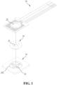
- FIG. 1 is an exploded schematic view of a heating mechanism according to an embodiment of the present invention.
- the heating mechanism of the biochemical reaction device of the present invention comprises a heat-conducting body 10 and a temperature control element 20, and the temperature control element 20 is connected to the heat-conducting body 10 for heat conducting and regulating the temperature change of the heat-conducting body 10.
- the heat-conducting body 10 may be formed with a recessed groove 101, and a limiting member 30 is disposed therein, so that related elements of the heat-conducting body 10 are limited therein.
- a clamping hole 12 provided in the heat-conducting body 10, a first through-hole 21 provided in the temperature control element 20 and a second through-hole 31 provided in the limiting member 30 are in communication with one another, so that a reaction container 40 (see FIG. 5 ) is clamped herein after inserting.
- the shape, length and outer diameter of the reaction container may be, but not limited to, designed according to the volume of the reaction solution and the shape of the corresponding heating mechanism.
- the reaction container may be a tubular container, such as the reaction tube 40 of the embodiment.
- the tubular container may be, but not limited to, a circular tube or a polygonal tube.
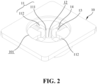
- FIG. 2 is a schematic view of a heat-conducting body in the heating mechanism according to an embodiment of the present invention.
- the structural shape of the heat-conducting body 10 is not particularly limited, and may be adjusted according to the requirements of the device, the size of the reaction tube, and the temperature control element.
- the clamping hole 12 of the heat-conducting body 10 is provided for insertion of the reaction tube 40.
- the clamping hole 12 may be a through-hole or a blind hole, as long as the reaction tube 40 can enter and be clamped therein.
- each accommodating groove 11 is disposed in the heat-conducting body 10, and each accommodating groove 11 includes a chamber 112 in which a heat-conducting block 13 is disposed, and the chamber 112 is extended to communicate with an opening 111, and the opening 111 is connected to the clamping hole 12.
- FIG. 3 is a top view of the heat-conducting body in the heating mechanism according to an embodiment of the present invention.
- the heat-conducting block 13 is disposed in the chamber 112 in a movable manner and one end of the heat-conducting block 13 is connected to an elastic member 14.
- the heat-conducting block 13 is pushed by an elastic force of the elastic member 14 towards against the opening 111.
- an abutting portion 131 of the heat-conducting block 13 is exposed to protrude from the opening 111 and is located in the clamping hole 12. Therefore, the opening 111 is sized to expose the abutting portion 131, but the heat-conducting block 13 as a whole is still located in the chamber 112.
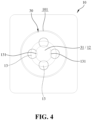
- FIG. 4 is a schematic view of the heat-conducting body after assembling a limiting member in the heating mechanism according to an embodiment of the present invention.
- the limiting member 30 can be installed in the recessed groove 101 of the heat-conducting body 10, and thus the heat-conducting block 13 and the like can be limited in the heat-conducting body 10. Therefore, the structure of the limiting member 30 is not particularly limited or does not necessarily have to be installed.
- the second through-hole 31 must also be provided to communicate with the clamping hole 12, so that the reaction tube 40 can pass and then be placed therein, and the abutting portion 131 of the heat-conducting block 13 is still exposed in the clamping hole 12, so that the reaction tube 40 can be in contact with the abutting portion 131 when inserted into the clamping hole 12, and thus be clamped by the action of the elastic force.
- FIG. 5 is a schematic view of the heating mechanism ready for insertion of the reaction tube according to an embodiment of the present invention
- FIG. 6A is a cross-sectional view of the heating mechanism without inserting the reaction tube according to an embodiment of the present invention
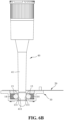
- FIG. 6B is a cross-sectional view of the heating mechanism after inserting the reaction tube according to an embodiment of the present invention.
- the temperature control element 20 is provided to regulate the temperature of the heat-conducting block 13, and the arrangement position and manner thereof are not particularly restricted, and may be provided, but not limited to, on a part or all of an upper surface of the heat-conductive body 10 (the surface facing the insertion direction of the reaction tube 40), a part or all of side surfaces of the heat-conductive body 10, or a part or all of a lower surface of the heat-conductive body 10 (the surface opposite to the upper surface).
- the temperature control element 20 is laid in shape matching on and connected to the upper surface of the heat-conducting body 10, and then the heat energy generated by the heating wire (not shown) disposed thereon is first transferred to the heat-conducting body 10, and then transferred to the heat-conducting block 13 for heating.
- the reaction tube 40 passes the first through-hole 21 of the temperature control unit 20 and the second through-hole 31 of the limiting member 30 and enters the clamping hole 12 of the heat-conducting body 10.
- the reaction tube 40 enters the clamping hole 12 since the abutting portions 131 of the heat-conducting blocks 13 protrude therein, and the inner diameter defined by the abutting portions 131 is smaller than the outer diameter of the tubular body 41 of the reaction tube 40, the reaction tube 40 will experience a hindrance of the clamping, and after a small force is applied, the outer wall of the front end of the tubular body 41 can push the abutting portion 131 of the heat-conducting block 13 towards the inside of the chamber 112 to overcome the action of the elastic force by an oblique component force through a surface of the heat-conducting block 13.
- the front end of the tubular body 41 can overcome the hindrance of the abutting portion 131 of the heat-conducting block 13 to pass through therebetween. After that, the tubular body 41 is clamped between the abutting portions 131/ the heat-conducting blocks 13. Thereafter, the subsequent reactions can be performed.
- the tubular body 41 of the reaction tube 40 may be provided with a heat-conducting element 411.
- the heat conducting element 411 may be disposed in a region configuration, a single side configuration or a circumferential configuration on the tubular body 41 according to the arrangement of the heat-conducting blocks 13.
- the heat-conducting element 411 is disposed in a circumferential configuration.
- the material of the heat-conducting element 411 is not particularly limited, but preferably has a higher heat transfer coefficient.
- the position of the heat-conducting element 411 should be corresponding to the position of the abutting portion 131, so that a heat can be transferred therebetween.
- the number and position of the accommodating grooves 11 are not particularly limited. It can be with only a single accommodating groove 11 and only an opening 111. Therefore, when the reaction tube 40 is inserted and clamped by the heat-conducting block 13, one-sided heating is performed.
- This heating way can be applied to, for example, a device for a convectional PCR.
- the accommodating grooves 11 may be disposed in a circumferential range of the arranging hole 12 by about 270 degrees to allow the openings 111 to face an outer edge of one side of the reaction tube 40 so that the plurality of heat-conducting blocks 13 performs one-sided heating.
- the accommodating grooves 11 / openings 111 may be equally spaced apart in the circumference of the clamping hole 12 to perform heating evenly on the circumference of the outer edge of the reaction tube 40. This can also be applied to a general PCR reaction device.
- FIG. 7 is a schematic view of a bottom portion of the heat-conducting body in the heating mechanism according to an embodiment of the present invention.
- a heat dissipation hole 15 communicating with the accommodating groove 11 may be provided.
- the position of the heat dissipation hole 15 is not particularly limited.
- the heat dissipation hole 15 is disposed at a bottom of the heat-conducting body 10, that is, a bottom of the accommodating groove 11, and the number of the heat dissipation holes may be determined, but not limited, according to the size of the structure or the range of the reaction temperature.
- FIG. 8A - FIG. 8F show various embodiments and designs of the abutting portion of the heat-conducting block.
- the purpose of the heat-conducting block 13 is to clamp the reaction tube 40 and to transfer heat. Therefore, the front end of the tubular body 41 can be smoothly passed through the abutting portions 131 and clamped between the abutting portions 131/ the heat-conducting blocks 13 as the reaction tube 40 is inserted.
- the abutting portion 131 has a spherical surface.
- the heat-conducting block 13 is a sphere, but may alternatively be an ellipsoidal, semi-ellipsoidal or hemispherical structure (not shown) and further directly connected to the elastic member 14.
- the heat-conducting block 13A shown in FIG. 8A and FIG. 8B has an abutting portion 131A with a hemispherical/semi-ellipsoidal structure according to the invention.
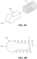
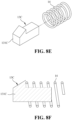
- the heat-conducting block 13B as shown in FIG. 8C and FIG. 8D has an abutting portion 131B with an arc-shaped structure, and the heat-conducting block 13C shown in FIG. 8E and FIG.
- the 8F has an abutting portion 131C with a sloped surface structure for the insertion of the reaction tube.
- the heat-conducting block is sleeve-connected to the elastic member 14 through a columnar extension structure.
- the elastic member 14 can be, but not limited to, a spring.
- the heat-conducting body 10 of the present invention is compact and small, and the reaction tube can be directly clamped, the accuracy and speed of heat transfer can be greatly improved. Therefore, reaction can be performed under the preset temperature in the reaction tube, and thus both the reaction efficiency and the product yield can be significantly improved.
Landscapes
- Health & Medical Sciences (AREA)
- Chemical & Material Sciences (AREA)
- Life Sciences & Earth Sciences (AREA)
- Chemical Kinetics & Catalysis (AREA)
- Clinical Laboratory Science (AREA)
- General Health & Medical Sciences (AREA)
- Biochemistry (AREA)
- Engineering & Computer Science (AREA)
- Bioinformatics & Cheminformatics (AREA)
- Molecular Biology (AREA)
- Wood Science & Technology (AREA)
- Zoology (AREA)
- Organic Chemistry (AREA)
- Biotechnology (AREA)
- Sustainable Development (AREA)
- General Engineering & Computer Science (AREA)
- Microbiology (AREA)
- Genetics & Genomics (AREA)
- Biomedical Technology (AREA)
- Medicinal Chemistry (AREA)
- Apparatus Associated With Microorganisms And Enzymes (AREA)
- Physical Or Chemical Processes And Apparatus (AREA)
- Automatic Analysis And Handling Materials Therefor (AREA)
Description
- The present invention relates generally to a heating device, and more particularly to a heating mechanism for heating or regulating the temperature of a reaction tube in a biochemical reaction device.
- Biochemical reaction devices, such as polymerase chain reaction (PCR) devices, must undergo loops of three reaction steps, including denaturation, annealing, and extension, when performing nucleic acid amplification reactions. Each reaction step has a preset optimal reaction temperature. For example, the denaturation reaction is generally set between about 90 and 95°C, the annealing reaction is set between about 35 to 65°C depending on the different primers, and the extension reaction is set at a temperature of about 72°C suitable for the polymerase reaction. The aforementioned reaction temperatures are closely correlated to the results of nucleic acid amplification, especially in the annealing reaction stage. If it is used to detect a target nucleic acid, the positive or negative determination is further affected by the reaction conditions. Therefore, accurate control of the reaction temperature is one of the important requirements of the device.
- In regard to the use of the heating mechanism in the polymerase chain reaction device, the reaction tubes containing the reaction solution are respectively placed into a heating module provided with a plurality of holes, thereby achieving the purpose of controlling the temperature of the reaction tubes through a heat conduction by the contact between an inner wall of the heating module and the reaction tubes. However, since the numerous types and specifications of the reaction tube will cause uneven or insufficient contact between the outer wall of the reaction tube and the hole of the heating module, this may result in the uneven temperature of the solution in the reaction tube or the solution may fail to reach the preset temperature, thereby lowering efficiency of the reaction or yield of the amplified product. When the reaction tubes are used to detect a specific target nucleic acid sequence, the accuracy of the detection result is also affected.
- In order to solve the above problem, mineral oil may be added to the hole to fill the gap between the reaction tube and the hole to improve heat transfer efficiency. However, the addition of mineral oil may easily cause sample contamination and cause mechanical cleaning and maintenance difficulties. More importantly, the mineral oil will also absorb and dissipate heat. After adding different volumes of mineral oil to the holes, there is also often a difference between the actual temperature and the preset temperature among the holes or even in the whole heating module. In addition, the heating module is bulky and thus requires a longer time to heat and dissipate heat, and therefore the required overall reaction time increases.
-
EP 1347833 B1 discloses a device for processing a biological sample that includes a processing unit having at least one opening to receive a sample vessel and a plurality of processing stations positioned along the opening. The processing stations each have a compression member adapted to compress the sample vessel within the opening and thereby move the sample within the sample vessel among the processing stations. An energy transfer element can be coupled to one or more of the processing stations for transferring thermal energy to the sample at a processing station. However,EP 1347833 B1 only provides a stationary member that can indirectly transfer heat to the sample vessel clamped by the compression member, and thus a heating efficiency needs to be improved. - The present invention provides a heating mechanism for a biochemical reaction device capable of conveniently placing a reaction container to be heated therein and capable of easily limiting the reaction container in a position. According to the heating mechanism of the present invention, the reaction container can be easily held and fixed in the heating mechanism by applying a thrust thereto but without deliberately adjusting the placement position of the reaction container, and then can be heated by heat conduction due to the clamping by the heat-conducting blocks thereon.
- The present invention also provides a heating mechanism capable of precisely regulating the temperature of a biochemical reaction. According to the heating mechanism of the present invention, the heat-conducting blocks can be in close and direct contact with the reaction container for heat conduction, so that the solution in the reaction container can assuredly reach the preset temperature. As such, the heating conditions of the respective reaction containers are consistent with each other, so that the reaction can be more efficiently performed with fast heat transfer, and the reproducibility and accuracy of the reaction result can also be improved.
- The present invention also provides a heating mechanism that can reduce the volume of a biochemical reaction device. According to the small and compact heating mechanism of the present invention, the same objective of the heat conduction can be achieved, but the required volume and space for the overall device can be reduced. Also, because of the compact size, it is more convenient in maintenance and replacement.
- The present invention also provides a heating mechanism for a biochemical reaction device capable of shortening the reaction time. According to the small and compact heating mechanism of the present invention, the heating time and the heat dissipation time can be shortened, so that the time required for the overall reaction is greatly shortened, and thus the reaction efficiency can be improved.
- The present invention provides a heating mechanism for a biochemical reaction device, comprising: a heat-conducting body, the heat-conducting body comprising: at least one accommodating groove each comprising a chamber and an opening communicating with the chamber; a clamping hole, in communication with the opening and for insertion of a reaction tube; at least one heat-conducting block, movably disposed in the chamber and having one end connected to an elastic element and another opposite end provided with an abutting portion, the elastic element enabling the abutting portion of the heat-conducting block to protrude from the opening and locate in the clamping hole; and a temperature control element, the temperature control element being connected to the heat-conducting body for heating and regulating a temperature of the heat-conducting block, characterised in that the abutting portion of the heat-conducting block is spherical.
- In an embodiment of the present invention, the heating mechanism of the biochemical reaction device further comprises a reaction container, and the reaction container may further be provided with a heat-conducting element. When the reaction container is inserted into the heat-conducting body through the clamping hole, the reaction container is pressed by the abutting portion of the heat-conducting block reaction hole so that the reaction container is clamped therein and the heat-conducting element is in contact with the heat-conducting block to conduct heat energy.
- In the heating mechanism of the biochemical reaction device according to an embodiment of the present invention, the accommodating groove is provided in plurality, and the openings provided in the accommodating grooves are distributed in a circumferential range of the clamping hole by about 270°, preferably a circumferential range of the clamping hole by about 180°, for one-sided heating the reaction tube. The accommodating grooves and the openings thereof may also be equally spaced apart in a circumference of the clamping hole to uniformly heat an outer edge of the reaction tube.
- In the heating mechanism of the biochemical reaction device according to an embodiment of the present invention, the temperature control element is laid on and connected to a surface of the heat-conducting body, and the temperature control element is provided with a first through-hole, the first through-hole is in communication with the clamping hole.
- In the heating mechanism of the biochemical reaction device according to an embodiment of the present invention, the abutting portion of the heat-conducting block is spherical, and thus the heat conducting block may be a shape of an ellipsoid, a sphere, a semi-ellipsoid or a hemisphere.
- In the heating mechanism of the biochemical reaction device according to an embodiment of the present invention, the heat-conducting body is further provided with a recessed groove on the accommodating groove, and a limiting member is disposed in the recessed groove. The limiting member is provided with a second through-hole, and the second through-hole is in communication with a first through-hole of the temperature control element, and the clamping hole.
- Since the reaction container for biochemical reaction can be easily placed in the clamping hole of the heat-conducting body of the present invention and clamped by the heat-conducting block, on the one hand, the reaction container can be fixed, and on the other hand, the direct contact between the reaction container and each heat-conducting block can be ensured. This avoids the disadvantage of the failure of contact between the outer edge of the reaction container and the heat-conducting block due to an offset placement of the reaction container. Therefore, not only the portion where the reaction container is in contact with the heat-conducting block can be heated uniformly, but also the consistency of the conditions of the heating reaction each time can be ensured, so that the biochemical reaction is reproducible and the reaction result is more accurate. In addition, since the reaction container is disposed in an insertion and clamping manner in the heating mechanism of the present invention, it is not necessary to provide a heating element or a heating module with a shape corresponding to that of the reaction container. Therefore, the reaction container or the heating device can be manufactured with a more widely allowable tolerance range, thereby reducing the manufacturing cost. On the other hand, because of the assured contact between the reaction container and the heat-conducting block, the heat energy can be quickly and precisely transferred to the reaction container. Therefore, the solution in the reaction tube can react accurately at the preset temperature, thereby further improving the reaction efficiency and the reaction accuracy.
- The embodiments of the present invention are further described below, and the following examples are set forth to illustrate the present invention, and are not intended to limit the scope of the present invention. Those skilled in the art can make various changes and modifications without departing from the spirit and scope of the present invention. Therefore, the protection scope of the present invention shall be defined by the appended claims.
-
-
FIG. 1 is an exploded schematic view of a heating mechanism according to an embodiment of the present invention. -
FIG. 2 is a perspective schematic view of a heat-conducting body in the heating mechanism according to an embodiment of the present invention. -
FIG. 3 is a top view of the heat-conducting body in the heating mechanism according to an embodiment of the present invention. -
FIG. 4 is a schematic view of the heat-conducting body after assembling a limiting member in the heating mechanism according to an embodiment of the present invention. -
FIG. 5 is a schematic view of the heating mechanism ready for insertion of a reaction tube therein according to an embodiment of the present invention. -
FIG. 6A is a cross-sectional view of the heating mechanism without inserting the reaction tube according to an embodiment of the present invention. -
FIG. 6B is a cross-sectional view of the heating mechanism after inserting the reaction tube according to an embodiment of the present invention. -
FIG. 7 is a schematic view of a bottom portion of the heat-conducting body in the heating mechanism according to an embodiment of the present invention. -
FIG. 8A is a schematic view of an abutting portion of a heat-conducting block in the heating mechanism according to an embodiment of the present invention. -
FIG. 8B is a cross-sectional view of the heat-conducting block ofFIG. 8A . -
FIG. 8C is a schematic view of an abutting portion of an alternative design of heat-conducting block in the heating mechanism not covered by the invention. -
FIG. 8D is a cross-sectional view of the heat-conducting block ofFIG. 8C . -
FIG. 8E is a schematic view of the abutting portion of another alternative design of heat-conducting block in the heating mechanism not covered by the invention. -
FIG. 8F is a cross-sectional view of the heat-conducting block ofFIG. 8E . - Referring to
FIG. 1, FIG. 1 is an exploded schematic view of a heating mechanism according to an embodiment of the present invention. The heating mechanism of the biochemical reaction device of the present invention comprises a heat-conductingbody 10 and atemperature control element 20, and thetemperature control element 20 is connected to the heat-conductingbody 10 for heat conducting and regulating the temperature change of the heat-conductingbody 10. For the convenience of assembling, the heat-conductingbody 10 may be formed with a recessedgroove 101, and a limitingmember 30 is disposed therein, so that related elements of the heat-conductingbody 10 are limited therein. A clampinghole 12 provided in the heat-conductingbody 10, a first through-hole 21 provided in thetemperature control element 20 and a second through-hole 31 provided in the limitingmember 30 are in communication with one another, so that a reaction container 40 (seeFIG. 5 ) is clamped herein after inserting. The shape, length and outer diameter of the reaction container may be, but not limited to, designed according to the volume of the reaction solution and the shape of the corresponding heating mechanism. Optionally, the reaction container may be a tubular container, such as thereaction tube 40 of the embodiment. The tubular container may be, but not limited to, a circular tube or a polygonal tube. - Referring to
FIG. 2, FIG. 2 is a schematic view of a heat-conducting body in the heating mechanism according to an embodiment of the present invention. The structural shape of the heat-conductingbody 10 is not particularly limited, and may be adjusted according to the requirements of the device, the size of the reaction tube, and the temperature control element. The clampinghole 12 of the heat-conductingbody 10 is provided for insertion of thereaction tube 40. The clampinghole 12 may be a through-hole or a blind hole, as long as thereaction tube 40 can enter and be clamped therein. In addition, at least one accommodatinggroove 11 is disposed in the heat-conductingbody 10, and eachaccommodating groove 11 includes achamber 112 in which a heat-conductingblock 13 is disposed, and thechamber 112 is extended to communicate with anopening 111, and theopening 111 is connected to the clampinghole 12. - Referring to
FIG. 2 andFIG. 3, FIG. 3 is a top view of the heat-conducting body in the heating mechanism according to an embodiment of the present invention. The heat-conductingblock 13 is disposed in thechamber 112 in a movable manner and one end of the heat-conductingblock 13 is connected to anelastic member 14. The heat-conductingblock 13 is pushed by an elastic force of theelastic member 14 towards against theopening 111. As such, an abuttingportion 131 of the heat-conductingblock 13 is exposed to protrude from theopening 111 and is located in the clampinghole 12. Therefore, theopening 111 is sized to expose the abuttingportion 131, but the heat-conductingblock 13 as a whole is still located in thechamber 112. - Referring to
FIG. 4, FIG. 4 is a schematic view of the heat-conducting body after assembling a limiting member in the heating mechanism according to an embodiment of the present invention. Furthermore, for the convenience of assembling, the limitingmember 30 can be installed in the recessedgroove 101 of the heat-conductingbody 10, and thus the heat-conductingblock 13 and the like can be limited in the heat-conductingbody 10. Therefore, the structure of the limitingmember 30 is not particularly limited or does not necessarily have to be installed. After the limitingmember 30 is installed, the second through-hole 31 must also be provided to communicate with the clampinghole 12, so that thereaction tube 40 can pass and then be placed therein, and the abuttingportion 131 of the heat-conductingblock 13 is still exposed in the clampinghole 12, so that thereaction tube 40 can be in contact with the abuttingportion 131 when inserted into the clampinghole 12, and thus be clamped by the action of the elastic force. - Referring to
FIG. 5 ,FIG. 6A andFIG. 6B ,FIG. 5 is a schematic view of the heating mechanism ready for insertion of the reaction tube according to an embodiment of the present invention;FIG. 6A is a cross-sectional view of the heating mechanism without inserting the reaction tube according to an embodiment of the present invention; andFIG. 6B is a cross-sectional view of the heating mechanism after inserting the reaction tube according to an embodiment of the present invention. Thetemperature control element 20 is provided to regulate the temperature of the heat-conductingblock 13, and the arrangement position and manner thereof are not particularly restricted, and may be provided, but not limited to, on a part or all of an upper surface of the heat-conductive body 10 (the surface facing the insertion direction of the reaction tube 40), a part or all of side surfaces of the heat-conductive body 10, or a part or all of a lower surface of the heat-conductive body 10 (the surface opposite to the upper surface). In the present embodiment, thetemperature control element 20 is laid in shape matching on and connected to the upper surface of the heat-conductingbody 10, and then the heat energy generated by the heating wire (not shown) disposed thereon is first transferred to the heat-conductingbody 10, and then transferred to the heat-conductingblock 13 for heating. In performing the heating, thereaction tube 40 passes the first through-hole 21 of thetemperature control unit 20 and the second through-hole 31 of the limitingmember 30 and enters the clampinghole 12 of the heat-conductingbody 10. When thereaction tube 40 enters the clampinghole 12, since the abuttingportions 131 of the heat-conductingblocks 13 protrude therein, and the inner diameter defined by the abuttingportions 131 is smaller than the outer diameter of thetubular body 41 of thereaction tube 40, thereaction tube 40 will experience a hindrance of the clamping, and after a small force is applied, the outer wall of the front end of thetubular body 41 can push the abuttingportion 131 of the heat-conductingblock 13 towards the inside of thechamber 112 to overcome the action of the elastic force by an oblique component force through a surface of the heat-conductingblock 13. At this moment, the front end of thetubular body 41 can overcome the hindrance of the abuttingportion 131 of the heat-conductingblock 13 to pass through therebetween. After that, thetubular body 41 is clamped between the abuttingportions 131/ the heat-conducting blocks 13. Thereafter, the subsequent reactions can be performed. - In order to further make the heat transfer more rapid and uniform, the
tubular body 41 of thereaction tube 40 may be provided with a heat-conductingelement 411. Theheat conducting element 411 may be disposed in a region configuration, a single side configuration or a circumferential configuration on thetubular body 41 according to the arrangement of the heat-conducting blocks 13. In the embodiment, the heat-conductingelement 411 is disposed in a circumferential configuration. Furthermore, the material of the heat-conductingelement 411 is not particularly limited, but preferably has a higher heat transfer coefficient. It should be noted that in the case where thereaction tube 40 is provided with the heat-conductingelement 411, after thereaction tube 40 is inserted, the position of the heat-conductingelement 411 should be corresponding to the position of the abuttingportion 131, so that a heat can be transferred therebetween. - It should be noted that the number and position of the
accommodating grooves 11 are not particularly limited. It can be with only a singleaccommodating groove 11 and only anopening 111. Therefore, when thereaction tube 40 is inserted and clamped by the heat-conductingblock 13, one-sided heating is performed. This heating way can be applied to, for example, a device for a convectional PCR. If a plurality ofaccommodating grooves 11 are provided, theaccommodating grooves 11 may be disposed in a circumferential range of the arranginghole 12 by about 270 degrees to allow theopenings 111 to face an outer edge of one side of thereaction tube 40 so that the plurality of heat-conductingblocks 13 performs one-sided heating. Alternatively, theaccommodating grooves 11 /openings 111 may be equally spaced apart in the circumference of the clampinghole 12 to perform heating evenly on the circumference of the outer edge of thereaction tube 40. This can also be applied to a general PCR reaction device. - Referring to
FIG. 7, FIG. 7 is a schematic view of a bottom portion of the heat-conducting body in the heating mechanism according to an embodiment of the present invention. In order to allow the heat-conductingbody 10 to dissipate heat rapidly after heating, aheat dissipation hole 15 communicating with theaccommodating groove 11 may be provided. The position of theheat dissipation hole 15 is not particularly limited. In the present embodiment, theheat dissipation hole 15 is disposed at a bottom of the heat-conductingbody 10, that is, a bottom of theaccommodating groove 11, and the number of the heat dissipation holes may be determined, but not limited, according to the size of the structure or the range of the reaction temperature. - Refer to
FIG. 8A - FIG. 8F , which show various embodiments and designs of the abutting portion of the heat-conducting block. The purpose of the heat-conductingblock 13 is to clamp thereaction tube 40 and to transfer heat. Therefore, the front end of thetubular body 41 can be smoothly passed through the abuttingportions 131 and clamped between the abuttingportions 131/ the heat-conductingblocks 13 as thereaction tube 40 is inserted. According to the invention the abuttingportion 131 has a spherical surface. In the embodiment ofFig.2 the heat-conductingblock 13 is a sphere, but may alternatively be an ellipsoidal, semi-ellipsoidal or hemispherical structure (not shown) and further directly connected to theelastic member 14. The heat-conductingblock 13A shown inFIG. 8A and FIG. 8B has anabutting portion 131A with a hemispherical/semi-ellipsoidal structure according to the invention. In alternative structures which are not according to the invention, the heat-conductingblock 13B as shown inFIG. 8C and FIG. 8D has anabutting portion 131B with an arc-shaped structure, and the heat-conductingblock 13C shown inFIG. 8E and FIG. 8F has anabutting portion 131C with a sloped surface structure for the insertion of the reaction tube. The heat-conducting block is sleeve-connected to theelastic member 14 through a columnar extension structure. Herein, theelastic member 14 can be, but not limited to, a spring. - Since the heat-conducting
body 10 of the present invention is compact and small, and the reaction tube can be directly clamped, the accuracy and speed of heat transfer can be greatly improved. Therefore, reaction can be performed under the preset temperature in the reaction tube, and thus both the reaction efficiency and the product yield can be significantly improved.
Claims (7)
- A heating mechanism for a biochemical reaction device, comprising:a heat-conducting body (10), the heat-conducting body (10) comprising:at least one accommodating groove (11) each comprising a chamber (112) and an opening (111) communicating with the chamber (112); anda clamping hole (12), in communication with the opening (111) and for insertion of a reaction tube (40);at least one heat-conducting block (13), movably disposed in the chamber (112) and having one end connected to an elastic element (14) and another opposite end provided with an abutting portion (131), the elastic element (14) enabling the abutting portion (131) of the heat-conducting block (13) to protrude from the opening (111) and locate in the clamping hole (12); anda temperature control element, being connected to the heat-conducting body (10) for heating and regulating a temperature of the heat-conducting block (13);characterised in that the abutting portion (131) of the heat-conducting block is spherical.
- The heating mechanism for the biochemical reaction device according to claim 1, wherein the accommodating groove (11) is provided in plurality, and the openings (111) provided in the accommodating grooves (11) are distributed in a circumferential range of the clamping hole (12) by about 270°.
- The heating mechanism for the biochemical reaction device according to claim 1, wherein the accommodating groove (11) is provided in plurality, and the openings (111) provided in the accommodating grooves (11) are evenly distributed in a circumference of the clamping hole (12).
- The heating mechanism for the biochemical reaction device according to claim 1, wherein the temperature control element (20) is laid on and connected to an upper surface, side surfaces or a lower surface of the heat-conducting body (10).
- The heating mechanism for the biochemical reaction device according to claim 1, wherein the heat-conducting block (13) is a sphere.
- The heating mechanism for the biochemical reaction device according to claim 1, wherein the heat-conducting body (10) is further provided with a recessed groove (101) on the accommodating groove (11), and a limiting member (30) is disposed in the recessed groove (101), the limiting member (30) is provided with a second through-hole (31), and the second through-hole (31) is in communication with a first through-hole (21) of the temperature control element (20), and the clamping hole (12).
- The heating mechanism for the biochemical reaction device according to claim 1, further comprising a reaction container (40), and the reaction container (40) being provided with a heat-conducting element (411), wherein when the reaction container (40) is inserted into the heat-conducting body (10) through the clamping hole (12), the reaction container (40) is pressed by the abutting portion (131) of the heat-conducting block (13) so that the reaction container (40) is clamped therein and the heat-conducting element (411) is in contact with the heat-conducting block (13) to conduct heat energy.
Applications Claiming Priority (1)
| Application Number | Priority Date | Filing Date | Title |
|---|---|---|---|
| PCT/CN2017/102233 WO2019056168A1 (en) | 2017-09-19 | 2017-09-19 | Heating mechanism for biochemical reaction device |
Publications (4)
| Publication Number | Publication Date |
|---|---|
| EP3686270A1 EP3686270A1 (en) | 2020-07-29 |
| EP3686270A4 EP3686270A4 (en) | 2021-05-05 |
| EP3686270C0 EP3686270C0 (en) | 2024-10-23 |
| EP3686270B1 true EP3686270B1 (en) | 2024-10-23 |
Family
ID=65810669
Family Applications (1)
| Application Number | Title | Priority Date | Filing Date |
|---|---|---|---|
| EP17926241.5A Active EP3686270B1 (en) | 2017-09-19 | 2017-09-19 | Heating mechanism for biochemical reaction device |
Country Status (5)
| Country | Link |
|---|---|
| US (1) | US11351553B2 (en) |
| EP (1) | EP3686270B1 (en) |
| KR (1) | KR102423452B1 (en) |
| CN (1) | CN110651033B (en) |
| WO (1) | WO2019056168A1 (en) |
Families Citing this family (2)
| Publication number | Priority date | Publication date | Assignee | Title |
|---|---|---|---|---|
| KR102873509B1 (en) | 2020-11-18 | 2025-10-17 | 아스테모 가부시키가이샤 | Electric actuator and drum brake for vehicle equipped therewith |
| CN114177965B (en) * | 2021-12-10 | 2022-09-13 | 河北德普环境监测有限公司 | Portable solvent heater |
Family Cites Families (19)
| Publication number | Priority date | Publication date | Assignee | Title |
|---|---|---|---|---|
| DK2333520T3 (en) * | 1997-02-28 | 2014-09-29 | Cepheid | Heat-exchanging, requested chemical reaction device |
| US6558947B1 (en) * | 1997-09-26 | 2003-05-06 | Applied Chemical & Engineering Systems, Inc. | Thermal cycler |
| US6780617B2 (en) * | 2000-12-29 | 2004-08-24 | Chen & Chen, Llc | Sample processing device and method |
| CA2523040C (en) * | 2003-05-23 | 2012-01-17 | Bio-Rad Laboratories, Inc. | Localized temperature control for spatial arrays of reaction media |
| IL156789A0 (en) | 2003-07-06 | 2004-02-08 | Adapter for multi-element contact-probe | |
| JP4813949B2 (en) * | 2006-03-31 | 2011-11-09 | 株式会社日立国際電気 | Thermocouple fixture and temperature control device for temperature object |
| GB0715171D0 (en) * | 2007-08-03 | 2007-09-12 | Enigma Diagnostics Ltd | Sample processor |
| US7955841B2 (en) | 2007-08-23 | 2011-06-07 | Akonni Biosystems | Temperature control device with a flexible temperature control surface |
| US8563907B2 (en) * | 2008-02-26 | 2013-10-22 | Mallinckrodt Llc | Radiopharmaceutical heater |
| CN101735949B (en) | 2008-11-05 | 2012-10-10 | 广达电脑股份有限公司 | variable temperature device |
| EP2615462B1 (en) * | 2010-11-15 | 2016-12-14 | F. Hoffmann-La Roche AG | Instrument and method for the automated thermal treatment of liquid samples |
| AU2013202793B2 (en) * | 2012-07-31 | 2014-09-18 | Gen-Probe Incorporated | System, method and apparatus for automated incubation |
| CN104293662B (en) | 2014-09-10 | 2016-08-17 | 瑞基海洋生物科技股份有限公司 | Biochemical reactor |
| US9731296B2 (en) * | 2014-12-19 | 2017-08-15 | Genereach Biotechnology Corp. | Biochemical reactor |
| TW201628718A (en) * | 2015-02-13 | 2016-08-16 | Genereach Biotechnology Corp | Heating device and biochemical reactor having the same |
| CN107530703B (en) | 2015-03-13 | 2020-02-07 | 瑞基海洋生物科技股份有限公司 | Heating device and biochemical reactor with same |
| DE102015121362B4 (en) * | 2015-12-08 | 2018-05-24 | Analytik Jena Ag | Temperature control device with a reaction vessel |
| US10729126B2 (en) * | 2017-01-16 | 2020-08-04 | Biolife Solutions, Inc. | Portable thawer components and features |
| CN106916743B (en) * | 2017-03-19 | 2019-02-12 | 北京化工大学 | Integrated nucleic acid extraction and amplification detection system |
-
2017
- 2017-09-19 KR KR1020197035005A patent/KR102423452B1/en active Active
- 2017-09-19 EP EP17926241.5A patent/EP3686270B1/en active Active
- 2017-09-19 US US16/628,526 patent/US11351553B2/en active Active
- 2017-09-19 WO PCT/CN2017/102233 patent/WO2019056168A1/en not_active Ceased
- 2017-09-19 CN CN201780090961.8A patent/CN110651033B/en active Active
Also Published As
| Publication number | Publication date |
|---|---|
| EP3686270C0 (en) | 2024-10-23 |
| US20200156078A1 (en) | 2020-05-21 |
| CN110651033B (en) | 2022-11-01 |
| US11351553B2 (en) | 2022-06-07 |
| WO2019056168A1 (en) | 2019-03-28 |
| EP3686270A1 (en) | 2020-07-29 |
| CN110651033A (en) | 2020-01-03 |
| KR102423452B1 (en) | 2022-07-20 |
| EP3686270A4 (en) | 2021-05-05 |
| KR20200003034A (en) | 2020-01-08 |
Similar Documents
| Publication | Publication Date | Title |
|---|---|---|
| US6657169B2 (en) | Apparatus for thermally cycling samples of biological material with substantial temperature uniformity | |
| US6638761B2 (en) | Thermal cycling device with mechanism for ejecting sample well trays | |
| JP5892709B2 (en) | Heating and cooling of low volume biological reaction vessels | |
| US6640891B1 (en) | Rapid thermal cycling device | |
| US20090190627A1 (en) | Performance testing apparatus for heat pipes | |
| US11351553B2 (en) | Heating mechanism for biochemical reaction device | |
| KR102811712B1 (en) | Sintering press for sintering electronic components on a substrate | |
| CA2382513C (en) | Apparatus and method for transporting sample well trays | |
| CN108348916B (en) | Temperature control device with reaction vessel | |
| CN216630892U (en) | Temperature control device applied to micro-fluidic chip and sample analyzer | |
| EP2338599B1 (en) | Laboratory apparatus with an arrangement for the tempering of samples and method of tempering samples | |
| EP3349902B1 (en) | System for biological analysis | |
| EP3085445B1 (en) | Apparatus for determining the temperature of microfluidic devices | |
| TWI624306B (en) | Heating mechanism of biochemical reaction device | |
| EP3519098B1 (en) | Sample container arrangement | |
| US20200398282A1 (en) | Temperature control device and genetic testing device | |
| JP5363463B2 (en) | Thermoelectric device and heat sink assembly with reduced end heat loss | |
| EP3056277B1 (en) | Tempering clamp | |
| CN221720775U (en) | Carrier | |
| CN116731842A (en) | Reaction tank device and PCR instrument | |
| CN224015663U (en) | Binary channels PCR detection device | |
| US20140338860A1 (en) | Combination Vessel Holder for Heat Block Incubation | |
| CN106950098B (en) | Incubation device of biological chip box | |
| WO2021181645A1 (en) | Analysis device, and flow cell securing structure | |
| CN115093930A (en) | Sealing cover and thermal cycle device |
Legal Events
| Date | Code | Title | Description |
|---|---|---|---|
| STAA | Information on the status of an ep patent application or granted ep patent |
Free format text: STATUS: THE INTERNATIONAL PUBLICATION HAS BEEN MADE |
|
| PUAI | Public reference made under article 153(3) epc to a published international application that has entered the european phase |
Free format text: ORIGINAL CODE: 0009012 |
|
| STAA | Information on the status of an ep patent application or granted ep patent |
Free format text: STATUS: REQUEST FOR EXAMINATION WAS MADE |
|
| 17P | Request for examination filed |
Effective date: 20200414 |
|
| AK | Designated contracting states |
Kind code of ref document: A1 Designated state(s): AL AT BE BG CH CY CZ DE DK EE ES FI FR GB GR HR HU IE IS IT LI LT LU LV MC MK MT NL NO PL PT RO RS SE SI SK SM TR |
|
| AX | Request for extension of the european patent |
Extension state: BA ME |
|
| DAV | Request for validation of the european patent (deleted) | ||
| DAX | Request for extension of the european patent (deleted) | ||
| A4 | Supplementary search report drawn up and despatched |
Effective date: 20210401 |
|
| RIC1 | Information provided on ipc code assigned before grant |
Ipc: C12M 1/38 20060101AFI20210326BHEP Ipc: B01L 7/00 20060101ALI20210326BHEP |
|
| STAA | Information on the status of an ep patent application or granted ep patent |
Free format text: STATUS: EXAMINATION IS IN PROGRESS |
|
| 17Q | First examination report despatched |
Effective date: 20240315 |
|
| REG | Reference to a national code |
Ref country code: DE Ipc: B01L0007000000 Ref legal event code: R079 Ref document number: 602017085724 Country of ref document: DE Free format text: PREVIOUS MAIN CLASS: C12M0001380000 |
|
| GRAP | Despatch of communication of intention to grant a patent |
Free format text: ORIGINAL CODE: EPIDOSNIGR1 |
|
| STAA | Information on the status of an ep patent application or granted ep patent |
Free format text: STATUS: GRANT OF PATENT IS INTENDED |
|
| RIC1 | Information provided on ipc code assigned before grant |
Ipc: B01L 7/00 20060101AFI20240612BHEP |
|
| INTG | Intention to grant announced |
Effective date: 20240627 |
|
| RIN1 | Information on inventor provided before grant (corrected) |
Inventor name: LI, FU-CHUN Inventor name: CHANG, HSIAO-FEN Inventor name: SU, CHEN Inventor name: LEE, PEI-YU Inventor name: TSAI, YUN-LUNG Inventor name: LIN, CHING-KO Inventor name: LEE, CHUN-MING |
|
| GRAS | Grant fee paid |
Free format text: ORIGINAL CODE: EPIDOSNIGR3 |
|
| GRAA | (expected) grant |
Free format text: ORIGINAL CODE: 0009210 |
|
| STAA | Information on the status of an ep patent application or granted ep patent |
Free format text: STATUS: THE PATENT HAS BEEN GRANTED |
|
| AK | Designated contracting states |
Kind code of ref document: B1 Designated state(s): AL AT BE BG CH CY CZ DE DK EE ES FI FR GB GR HR HU IE IS IT LI LT LU LV MC MK MT NL NO PL PT RO RS SE SI SK SM TR |
|
| REG | Reference to a national code |
Ref country code: GB Ref legal event code: FG4D |
|
| REG | Reference to a national code |
Ref country code: CH Ref legal event code: EP |
|
| REG | Reference to a national code |
Ref country code: DE Ref legal event code: R096 Ref document number: 602017085724 Country of ref document: DE |
|
| REG | Reference to a national code |
Ref country code: IE Ref legal event code: FG4D |
|
| U01 | Request for unitary effect filed |
Effective date: 20241029 |
|
| U07 | Unitary effect registered |
Designated state(s): AT BE BG DE DK EE FI FR IT LT LU LV MT NL PT RO SE SI Effective date: 20241104 |
|
| PG25 | Lapsed in a contracting state [announced via postgrant information from national office to epo] |
Ref country code: HR Free format text: LAPSE BECAUSE OF FAILURE TO SUBMIT A TRANSLATION OF THE DESCRIPTION OR TO PAY THE FEE WITHIN THE PRESCRIBED TIME-LIMIT Effective date: 20241023 Ref country code: IS Free format text: LAPSE BECAUSE OF FAILURE TO SUBMIT A TRANSLATION OF THE DESCRIPTION OR TO PAY THE FEE WITHIN THE PRESCRIBED TIME-LIMIT Effective date: 20250223 |
|
| PG25 | Lapsed in a contracting state [announced via postgrant information from national office to epo] |
Ref country code: ES Free format text: LAPSE BECAUSE OF FAILURE TO SUBMIT A TRANSLATION OF THE DESCRIPTION OR TO PAY THE FEE WITHIN THE PRESCRIBED TIME-LIMIT Effective date: 20241023 |
|
| PG25 | Lapsed in a contracting state [announced via postgrant information from national office to epo] |
Ref country code: NO Free format text: LAPSE BECAUSE OF FAILURE TO SUBMIT A TRANSLATION OF THE DESCRIPTION OR TO PAY THE FEE WITHIN THE PRESCRIBED TIME-LIMIT Effective date: 20250123 |
|
| PG25 | Lapsed in a contracting state [announced via postgrant information from national office to epo] |
Ref country code: GR Free format text: LAPSE BECAUSE OF FAILURE TO SUBMIT A TRANSLATION OF THE DESCRIPTION OR TO PAY THE FEE WITHIN THE PRESCRIBED TIME-LIMIT Effective date: 20250124 |
|
| PG25 | Lapsed in a contracting state [announced via postgrant information from national office to epo] |
Ref country code: PL Free format text: LAPSE BECAUSE OF FAILURE TO SUBMIT A TRANSLATION OF THE DESCRIPTION OR TO PAY THE FEE WITHIN THE PRESCRIBED TIME-LIMIT Effective date: 20241023 |
|
| PG25 | Lapsed in a contracting state [announced via postgrant information from national office to epo] |
Ref country code: RS Free format text: LAPSE BECAUSE OF FAILURE TO SUBMIT A TRANSLATION OF THE DESCRIPTION OR TO PAY THE FEE WITHIN THE PRESCRIBED TIME-LIMIT Effective date: 20250123 |
|
| PG25 | Lapsed in a contracting state [announced via postgrant information from national office to epo] |
Ref country code: SM Free format text: LAPSE BECAUSE OF FAILURE TO SUBMIT A TRANSLATION OF THE DESCRIPTION OR TO PAY THE FEE WITHIN THE PRESCRIBED TIME-LIMIT Effective date: 20241023 |
|
| PG25 | Lapsed in a contracting state [announced via postgrant information from national office to epo] |
Ref country code: SK Free format text: LAPSE BECAUSE OF FAILURE TO SUBMIT A TRANSLATION OF THE DESCRIPTION OR TO PAY THE FEE WITHIN THE PRESCRIBED TIME-LIMIT Effective date: 20241023 |
|
| PG25 | Lapsed in a contracting state [announced via postgrant information from national office to epo] |
Ref country code: CZ Free format text: LAPSE BECAUSE OF FAILURE TO SUBMIT A TRANSLATION OF THE DESCRIPTION OR TO PAY THE FEE WITHIN THE PRESCRIBED TIME-LIMIT Effective date: 20241023 |
|
| PLBE | No opposition filed within time limit |
Free format text: ORIGINAL CODE: 0009261 |
|
| STAA | Information on the status of an ep patent application or granted ep patent |
Free format text: STATUS: NO OPPOSITION FILED WITHIN TIME LIMIT |
|
| U20 | Renewal fee for the european patent with unitary effect paid |
Year of fee payment: 9 Effective date: 20250807 |
|
| 26N | No opposition filed |
Effective date: 20250724 |
|
| U1N | Appointed representative for the unitary patent procedure changed after the registration of the unitary effect |
Representative=s name: STEVENS HEWLETT & PERKINS; GB |
|
| REG | Reference to a national code |
Ref country code: CH Ref legal event code: H13 Free format text: ST27 STATUS EVENT CODE: U-0-0-H10-H13 (AS PROVIDED BY THE NATIONAL OFFICE) Effective date: 20260504 |