EP3686151A1 - Flurförderzeug mit standplattform - Google Patents
Flurförderzeug mit standplattform Download PDFInfo
- Publication number
- EP3686151A1 EP3686151A1 EP20153529.1A EP20153529A EP3686151A1 EP 3686151 A1 EP3686151 A1 EP 3686151A1 EP 20153529 A EP20153529 A EP 20153529A EP 3686151 A1 EP3686151 A1 EP 3686151A1
- Authority
- EP
- European Patent Office
- Prior art keywords
- suspension
- pivot axis
- industrial truck
- base element
- spring
- Prior art date
- Legal status (The legal status is an assumption and is not a legal conclusion. Google has not performed a legal analysis and makes no representation as to the accuracy of the status listed.)
- Granted
Links
Images



Classifications
-
- B—PERFORMING OPERATIONS; TRANSPORTING
- B66—HOISTING; LIFTING; HAULING
- B66F—HOISTING, LIFTING, HAULING OR PUSHING, NOT OTHERWISE PROVIDED FOR, e.g. DEVICES WHICH APPLY A LIFTING OR PUSHING FORCE DIRECTLY TO THE SURFACE OF A LOAD
- B66F9/00—Devices for lifting or lowering bulky or heavy goods for loading or unloading purposes
- B66F9/06—Devices for lifting or lowering bulky or heavy goods for loading or unloading purposes movable, with their loads, on wheels or the like, e.g. fork-lift trucks
- B66F9/075—Constructional features or details
- B66F9/0759—Details of operating station, e.g. seats, levers, operator platforms, cabin suspension
-
- B—PERFORMING OPERATIONS; TRANSPORTING
- B62—LAND VEHICLES FOR TRAVELLING OTHERWISE THAN ON RAILS
- B62D—MOTOR VEHICLES; TRAILERS
- B62D33/00—Superstructures for load-carrying vehicles
- B62D33/06—Drivers' cabs
- B62D33/0604—Cabs insulated against vibrations or noise, e.g. with elastic suspension
-
- B—PERFORMING OPERATIONS; TRANSPORTING
- B62—LAND VEHICLES FOR TRAVELLING OTHERWISE THAN ON RAILS
- B62D—MOTOR VEHICLES; TRAILERS
- B62D51/00—Motor vehicles characterised by the driver not being seated
- B62D51/02—Motor vehicles characterised by the driver not being seated the driver standing in the vehicle
-
- B—PERFORMING OPERATIONS; TRANSPORTING
- B62—LAND VEHICLES FOR TRAVELLING OTHERWISE THAN ON RAILS
- B62D—MOTOR VEHICLES; TRAILERS
- B62D51/00—Motor vehicles characterised by the driver not being seated
- B62D51/001—Motor vehicles characterised by the driver not being seated characterised by the vehicle control device
Definitions
- Industrial truck with a drive part and a stand platform arranged on the drive part for an operator, the stand platform having a base element pivotable about a first pivot axis fixed to the vehicle and a base element mounted pivotably on the base element about a second pivot axis, the first pivot axis and the second pivot axis being parallel to one another extend and are arranged offset from one another along a longitudinal axis of the vehicle, the base element extending above the base element forming the base for the operator, the base element being supported on the industrial truck by a first suspension during its pivoting movement about the first pivot axis.
- a standing platform which is mounted via a lever arm mounted about a pivot axis on a spring arrangement which is supported on a frame of the industrial truck.
- the standing platform itself also acts as a contrary lever arm around the swivel axis. If an operator stands close to the swivel axis, he hardly experiences any spring action, whereas if the distance from the swivel axis is relatively large, the spring action is uncomfortably high.
- a standing platform is known with an upper base plate which is articulated on a lower base plate, a spring element being arranged between the base plates.
- the spring action is only high in the vicinity of the spring, while the spring action decreases considerably as the distance from the spring increases.
- EP 1 205 427 A1 describes an industrial truck with an elastically supported stand platform with spring elements and guide means which are designed separately from the spring elements, the guide means being in contact with the vehicle frame and with the stand platform via cross struts. This construction is very complex to manufacture and maintain.
- a rectangular floor plate is known as a standing platform, which has a spring element at each of its corners.
- a stand platform On such a stand platform, an operator has a very spongy stand and therefore has great problems with balance.
- Stand platforms mentioned at the beginning are, for example, from DE 10 2015 102 583 A1 known.
- a base element is pivotally mounted on a vehicle frame about a first pivot axis and is connected to a stand element for an operator via a second pivot axis.
- a suspension extends between the vehicle frame and the stand element and thus supports the stand element as well as the base element coupled to it together against movements about their pivot axes.
- the stand element has a vertical section with a guide roller which rolls along a guide fixed to the vehicle when a weight is exerted on the stand platform. This construction is very complex.
- a comparable stand platform is known, which also between Has vehicle frame and standing platform acting, switchable damping units. This standing platform has the same disadvantages.
- the object of the invention is to provide an industrial truck with a standing platform which allows a uniform suspension over the entire area of the standing platform in a structurally simple manner.
- the standing element is supported by a second suspension during its pivoting movement about the second pivot axis, and the first suspension is arranged at a distance from the first pivot axis along the vehicle longitudinal axis.
- the industrial truck can also have a load part, wherein the load part can in particular have a lifting mast and / or load forks.
- the drive part can in particular have a drive, for example an electric motor, and batteries that supply power to the electric motor.
- the industrial truck can be, for example, a forklift, in particular a high-lift truck or a low-lift truck.
- the stand platform comprises the stand element and the base element and is therefore formed in two parts. The stand element extends at least in a use position of the stand platform above the base element and forms the stand area for the operator.
- the base element can be pivoted about the first pivot axis fixed to the vehicle and is supported on the vehicle via the first suspension, for example on a vehicle frame, in particular a drive frame of the drive part.
- a swivel axis fixed to the vehicle means a swivel axis fixed to the truck.
- Vehicle and industrial truck are used synonymously in the present case.
- the stand element can be pivoted about the second pivot axis, independently of the basic element.
- a second suspension which is separate from the first suspension and supports the standing element.
- the springs support the base element and the stand element independently of each other.
- the first suspension thus supports the base element, for example against an underbody of the vehicle.
- the second suspension supports the standing element independently of the first suspension, for example also against an underbody of the vehicle or against the base element.
- the first suspension and the second suspension are not identical, for example can be realized by separate spring elements.
- the first suspension and the second suspension can in particular be offset from one another along the longitudinal axis of the vehicle, as will be explained.
- the first suspension is spaced apart from the first pivot axis along the longitudinal axis of the vehicle.
- the first suspension is therefore not arranged at the same length position as the first pivot axis in relation to the longitudinal axis of the vehicle.
- the first pivot axis can be arranged at a first end of the base element and the first suspension at a second end of the base element opposite the first end along the vehicle longitudinal axis.
- the second suspension can also be arranged at a distance from the second pivot axis along the longitudinal axis of the vehicle.
- Such a standing platform is structurally simple, in particular, a vertical section with a guide roller can be dispensed with in a structurally simple manner, as described for the standing platform of the opening paragraph DE 10 2015 102 583 A1 is provided.
- one-sided lever forces are compensated for with the vertical section, which arise in particular from the suspension on one side only.
- there is a compensation such lever forces in particular due to the displacement of the first suspension away from the first pivot axis and by the support of the pivoting movement about the second pivot axis via a second suspension. This is not only less complex in terms of design but also in maintenance.
- the standing platform according to the invention enables a very uniform suspension over its entire surface.
- the first suspension and the second suspension are offset from one another along the longitudinal axis of the vehicle.
- the suspensions can support the movements about the respective pivot axes particularly well, that is, dampen them.
- the lever forces of the levers formed by the base element and the stand element can be absorbed easily and in a structurally simple manner.
- the first pivot axis is arranged at a first end of the base element and the first suspension is arranged at a second end of the base element opposite the first end along the vehicle longitudinal axis between the base element and an underbody of the industrial truck that extends below the base element.
- the inventive spacing of the first suspension from the first pivot axis along the vehicle's longitudinal axis can be implemented in a particularly simple manner.
- the first suspension is in particular arranged at the second end of the base element such that the lever forces exerted by the base element during its movement about the first pivot axis are optimally damped.
- the second suspension can be offset from the first suspension along the longitudinal axis of the vehicle.
- the second pivot axis can be arranged at a first end of the stand element and the second suspension can be arranged at a second end of the stand element opposite the first end along the vehicle longitudinal axis.
- the leverage of the stand element can also Movement around the second pivot axis can be well balanced.
- the support of the standing element via the second suspension can take place directly via the base element or via the industrial truck, as will be explained later.
- the first suspension is arranged on a lever arm which extends from the base element and extends along the longitudinal axis of the vehicle from the two pivot axes.
- the lever arm can extend in particular towards a load part of the industrial truck.
- the base element can form a type of rocker with the lever arm, which is pivotally mounted about the first pivot axis.
- the entire standing platform can thus be mounted on the industrial truck like a lever.
- the first suspension can be arranged between one end of the base element and a sub-floor of the industrial truck via the lever arm extending from the base element, the lever arm in particular being able to act on the end of the base element on which the first pivot axis is arranged.
- the base element and thus in particular the entire standing platform can thus also be supported on the industrial truck via an end protruding from the second pivot axis in the direction of the load part.
- the first suspension can be connected to a drive frame of the industrial truck.
- the base element can be suspended from the drive frame via the first suspension.
- This also allows the inventive spacing of the first suspension from the first pivot axis along the vehicle longitudinal axis to be particularly realized.
- the support explained above with respect to an underbody can be dispensed with, as a result of which the standing platform according to the invention can in particular also be designed so that it can be folded in and out.
- the second suspension is arranged such that the spring effect exerted by the second suspension is greatest in the region of the first pivot axis and / or the first suspension is arranged such that the first suspension exerted spring action is greatest in the region of the second pivot axis.
- the first suspension and / or the second suspension are arranged in such a way that this disadvantage is compensated for.
- the second suspension is arranged in the region of the first pivot axis and / or the first suspension is arranged in the region of the second pivot axis.
- the standing element can be supported directly on the base element or else on the industrial truck during its pivoting movement about the second pivot axis in the region of the first pivot axis, as already mentioned above. Due to the second suspension, a sufficiently high spring effect can also be achieved in the area of the first pivot axis - where the first suspension usually has hardly any spring action - or due to the first suspension also in the area of the second pivot wax - where the second suspension usually has hardly any spring action can be achieved.
- the spatial proximity to the respective swivel axis denotes the positioning of the respective suspension in spatial proximity to the respective other swivel axis.
- the spatial proximity can in particular be selected such that the spring effect exerted by the first suspension is greatest in the region of the second pivot axis or that the spring effect exerted by the second suspension is greatest in the region of the first pivot axis.
- the first pivot axis runs at a first end of the base element connected to the industrial truck and the second pivot axis runs at a second end of the base element opposite the first end on the vehicle longitudinal axis.
- the second end can in particular be a free end of the base element.
- the two pivot axes can therefore run in particular at opposite ends of the base element.
- the second pivot axis can run at a first end of the stand element, which can lie opposite a second, in particular free end of the stand element.
- the standing element is supported on the base element and / or on the industrial truck during its pivoting movement about the second pivot axis via the second suspension.
- the stand element can be supported directly on the industrial truck.
- the second suspension can then be arranged between the stand element and the industrial truck, in particular between one end of the stand element and a drive frame of the industrial truck.
- the second suspension can also support the pivoting movement of the standing element about the second pivot axis on the base element and in particular not directly on the industrial truck.
- the second suspension can be arranged, for example, between the stand element and the base element.
- the base element can in particular support the stand element.
- the stand element can only be arranged on the industrial truck via the base element without direct contact with the industrial truck.
- both the stand element and the base element - that is to say ultimately the entire stand platform - can be pivoted about the first pivot axis and are supported on the industrial truck via the first suspension.
- the first suspension can be used to support a vehicle frame, for example a drive frame of the drive part, as already mentioned.
- a common support of the stand element and base element via only one suspension would not, however, cover the entire Allow surface of the standing platform to have a uniform spring action, but, as explained at the beginning, leads to a varying spring force depending on the distance to the suspension. This is in particular due to the fact that a lever arm acting around the first pivot axis has a different length depending on the standing position of the operator on the standing platform.
- the second suspension which, according to the present embodiment, supports the stand element with respect to the base element.
- the second suspension can therefore develop a strong spring effect, in particular at the points on the standing platform, where only a small spring effect can be generated due to the first suspension. Accordingly, the second suspension can have a low spring action where the first suspension has a large spring action.
- the stand element can be supported on the base element via the second suspension in the region of the first pivot axis. A high level of comfort for the operator can thus be achieved for a standing platform with two pivot axes.
- the base element has two support arms and a cross arm connecting the support arms to one another.
- the second suspension is arranged between the cross arm and the standing element.
- the stand element can therefore be supported in particular on the cross arm of the base element.
- the stand platform is designed to be adjustable about the first pivot axis between an extended use position in which the stand element extends essentially horizontally and a folded stowage position on the industrial truck in which the stand element extends essentially vertically.
- the standing platform can thus be designed to be foldable or foldable. If the industrial truck is not used, the standing platform can be folded in, in particular folded up, on the industrial truck to be stowed with it. To use the industrial truck, the standing platform can be folded out of the stowed position into the use position, in particular folded down, and used by an operator.
- the stand element is preferably supported on the base element and also moves the stand element with a corresponding movement of the base element about the first pivot axis.
- the entire stand platform is moved between the stowed position and the use position.
- the standing platform can in particular be moved about a pivoting direction about the first pivot axis, which is opposite to the pivoting movement about the first pivot axis, in which the first suspension supports the base element with respect to the vehicle.
- the stand platform can thus be stowed away in a practical way.
- the first suspension and the second suspension have different spring forces. Since different suspensions are provided, it is also possible to provide different spring forces for the different suspensions.
- the spring forces of the suspensions can differ in such a way that the uniform spring action explained above can be achieved over the entire surface of the standing platform.
- the spring force provided for a suspension can depend on the point at which the respective suspension engages the base element or the standing element. Lever arms of different lengths can thus be taken into account.
- the first suspension and / or the second suspension comprises one or more spring elements from the following set: steel spring, coil spring, plate spring, elastomer spring, rubber spring.
- the coil spring can be made of steel, the elastomer spring can be a polyurethane spring, for example.
- the industrial truck comprises a fixing mechanism which fixes the stand element on the base element, in particular in a detachable manner.
- the fixing mechanism has at least two fixing means corresponding to one another, wherein a first fixing means can be arranged on the base element and a second fixing means on the base element.
- the fixing mechanism can comprise, for example, a bolt engaging in a bolt receptacle or a screw engaging in a receptacle, which can be held on the receptacle in particular via a nut.
- the spring action of the second suspension can be adjusted via the fixing mechanism. Such adjustability can be achieved, for example, by changing the compression of the second suspension, in particular by changing the distance between the stand element and the base element. For example, a screw can be tightened further.
- FIG 1 an industrial truck 10 according to the invention with a drive part 12 and a standing platform 14 can be seen.
- the drive part 12 has a tiller head 16 with operating elements for controlling the industrial truck by an operator standing on the standing platform 14.
- the standing platform 14 is partially framed by lateral holding struts 18, which offer support to an operator located on the standing platform, particularly when cornering.
- a load part can be provided on the front of the industrial truck 10 adjacent to the drive part 12, on the side of the drive part 12 opposite the standing platform 14. Such a load part, not shown, serves to move loads through the industrial truck 10.
- the standing platform 14 in Figure 2 can be seen in an exploded view, it becoming clear that the standing platform is formed in two parts.
- the standing platform 14 comprises a base element 20 and a stand element 22.
- the base element 20 comprises a cross arm 24 which connects two support arms 26 running parallel to one another at a first of their ends. At the opposite ends of the support arms 26, a bearing rod 28 extends between the support arms.
- the base element 20 is pivotally mounted on the drive frame of the industrial truck 10 in a manner not shown via bearing pins 30 arranged at the first end of the support arms 26. Which differ from the outside of each other opposite support arms 26 extending bearing journal 30 can be accommodated in correspondingly designed bearing receptacles in the drive frame.
- the base element 20 is thus mounted on the industrial truck so as to be pivotable about a first pivot axis S 1 , which extends through the mutually opposite bearing journals 30.
- the standing element 22 is flat and, in the present exemplary embodiment, has reinforcing struts 32 running on its underside.
- Bearing receptacles 34 formed at a first end of the standing element 22, receive its bearing rod 28 in the state connected to the base element 20.
- the standing element 22 is thus mounted on the base element 20 so as to be pivotable about a second pivot axis S 2 , which extends through the mutually opposite bearing receptacles 34 and the bearing rod 28.
- a second suspension which comprises two spring elements, of which a first spring element 36 is designed as a helical spring and a second spring element 38 as a rubber spring is arranged at a second end of the standing element 22 opposite the first end.
- both spring elements are designed as coil springs or rubber springs or otherwise.
- the stand element 22 is supported on the cross arm 24 of the base element 20 via the spring elements 36, 38, as in particular in FIG Figure 3 to recognize.
- FIG Figure 3 shows the two-part standing platform in the connected state of base element 20 and standing element 22 in a sectional view, the bearing rod 28 being accommodated in the bearing receptacles 34 in the manner explained and the spring elements 36 and that in FIG Figure 3 not visible spring element 38 come into contact with the cross arm 24.
- a fixing mechanism comprising a screw 40 extending from the stand element 22 in the direction of the base element 20 and a screw receiver 42 arranged on the base element 20 Stand element 22 and base element 20 engages screw 40 in screw receptacle 42 and can be fastened with a nut from the side of screw receptacle 42 facing away from stand element 22.
- the stand element 22 is securely held on the base element 20 in a detachable manner.
- the hardness of the second suspension can be adjusted via the fixing mechanism. With increasing screwing of the nut on the screw 40, the standing platform 22 is pulled closer to the base element 20 and thus the spring elements 36, 38 of the second suspension are compressed more.
- the base element 20 is supported by a first suspension 44 on a drive frame 13 of the industrial truck.
- the first suspension 44 in the present case comprising a coil spring, is arranged in a bell 46 connected to the vehicle frame 13.
- the first suspension 44 is arranged along a vehicle longitudinal axis L at a distance from the first pivot axis S 1 .
- the pivot axes S 1 , S 2 are also spaced apart from one another along the vehicle longitudinal axis L.
- the standing platform 14 is now loaded with weight, for example by an operator climbing onto the standing platform, a weight force acts along the in Figure 3 Arrow line marked G on the standing platform 14.
- this causes the entire standing platform 14, that is to say both the standing element 22 and the base element 20, to be pivoted about the first pivot axis S 1 .
- This movement is supported by the first suspension 44.
- the first spring element 44 is compressed via a lever arm 48 which extends from the first pivot axis S 1 into the drive part.
- the stand element 22 is also pivoted about the second pivot axis S 2 , as a result of which the second suspension 36, 38 is compressed. There is thus a double suspension of the operator.
- the respective suspensions can compensate for the disadvantages of the other suspension.
- the first suspension 36, 38 is arranged in the region of the first pivot axis S 1 , the stand element 22 thus experiences a great spring effect in the region of the first pivot axis S 1 via the second suspension 36, 38.
- the spring action of the first suspension 44 is particularly low due to the low leverage effect.
- the spring action of the first suspension 44 is large due to a very large lever acting with respect to the first pivot axis S 1, and the spring action due to the second suspension 36, 38 is low due to the large distance to this suspension.
- the spring action of the second suspension 36, 38 continues to decrease, but the spring action of the first suspension 44 continues to increase.
- the second suspension is thus arranged such that the spring effect exerted by the second suspension is greatest in the region of the first pivot axis and the first suspension is arranged such that the spring effect exerted by the first suspension is greatest in the region of the second pivot axis.
- the spacing of the first suspension 44 and the first pivot axis S 1 from one another along the longitudinal axis L via the lever arm 48 allows the base element 20 and thus the entire standing platform 14 to be suspended on the drive frame 13 in a structurally simple manner , in particular without the need for a vertical section with a guide roller rolling on the drive frame, a uniform suspension over the entire standing platform.
- FIG 4 a purely schematic view shows a further embodiment of a stand platform according to the invention, the structure of which essentially corresponds to the previously explained embodiment.
- This stand platform 14 ' also comprises a base element 20' and a stand element 22 'extending above the base element.
- the base element 20 ' can be pivoted about a first pivot axis S 1 fixed to the vehicle via a first support 50.
- the support 50 is fixedly connected to the drive frame 13.
- the first pivot axis S 1 supports the base element 20 'on the drive frame 13 via a first suspension 44', a lever arm 48 'of the base element 20' engaging the first suspension 44 '.
- the base element 20 ' carries the stand element 22', so that this and thus the entire stand platform 14 'are supported on the vehicle frame 13 by the first suspension 44 when they move together about the first pivot axis S 1 .
- the stand element 22 ' is also pivotably mounted about the second pivot axis S 2 with respect to the base element 20' and is supported with respect to the base element 20 'via the second suspension 36'.
- a spring effect which is essentially constant over the entire standing platform can be achieved in a structurally simple manner.
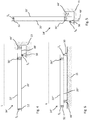
- Figure 5 shows the standing platform 14 ' Figure 4 in a stowed position. In this position, the standing platform 14 'is folded up by about 90 ° on the industrial truck and can therefore be stowed away to save space. To use the standing platform 14 ', it can be moved from the stowed position in Figure 5 can be folded down by 90 ° into the Figure 4 obvious use. Also the representation in Figure 5 is purely schematic.
- the lever arm 48 ' can basically engage in recesses in the vehicle frame 13.
- FIG. 6 shows a roughly schematic representation of a standing platform 14 "with a differently arranged first suspension 44".
- the first suspension 44 is not arranged on a lever arm of the base element 20" pointing away from the second pivot axes S 2 , but instead on a second end of the base element 20 "in the region of the second pivot axis S 2 between an underside of the base element 20" and one extending underbody 15 of the truck.
- the second end of the base element 20 “designates the end opposite a first end having the first pivot axis S 1.
- the first Suspension 44 is thus arranged along the longitudinal axis L of the vehicle at a distance from the first pivot axis S 1 , whereby the structurally simple configuration of the standing platform is achieved.
- the spring effect exerted by the first suspension 44" is as large as possible in the region of the second pivot axis S 2 . This configuration also enables a uniform spring action to be achieved over the entire standing platform.
- FIG. 7 also shows a roughly schematic representation of a further embodiment of a standing platform 14 ′′. This differs from that in FIG Figure 6 Stand platform 14 "shown merely in that the second suspension 36" is not arranged between the stand element 22 “and the base element 20” but between one end of the stand element 22 "and the underbody 15 of the industrial truck.
- the stand element 22" is pivoting about the second Pivot axis S 2 is thus supported via the second suspension 36 "not on the base element (20, 20 ', 20") but directly on the industrial truck.
Landscapes
- Engineering & Computer Science (AREA)
- Transportation (AREA)
- Mechanical Engineering (AREA)
- Structural Engineering (AREA)
- Chemical & Material Sciences (AREA)
- Combustion & Propulsion (AREA)
- Civil Engineering (AREA)
- Life Sciences & Earth Sciences (AREA)
- Geology (AREA)
- Vehicle Body Suspensions (AREA)
Abstract
Description
- Flurförderzeug mit einem Antriebsteil und einer an dem Antriebsteil angeordneten Standplattform für eine Bedienperson, wobei die Standplattform ein um eine fahrzeugfeste erste Schwenkachse verschwenkbares Basiselement und ein an dem Basiselement um eine zweite Schwenkachse verschwenkbar gelagertes Standelement aufweist, wobei die erste Schwenkachse und die zweite Schwenkachse parallel zueinander verlaufen und entlang einer Fahrzeuglängsachse zueinander versetzt angeordnet sind, wobei das Standelement sich oberhalb des Basiselements erstreckend die Standfläche für die Bedienperson bildet, wobei das Basiselement bei seiner Schwenkbewegung um die erste Schwenkachse über eine erste Federung an dem Flurförderzeug abgestützt ist.
- Bei Flurförderzeugen mit Standplattformen für eine Bedienperson, also für einen Fahrer des Flurförderzeugs, fährt die Bedienperson auf der Plattform stehend mit dem Flurförderzeug mit. Die Bedienperson steuert dabei das Flurförderzeug über ein oder mehrere Bedienelemente, die insbesondere an einem Deichselkopf angeordnet sind. Standplattformen für solche Flurförderzeuge sind üblicherweise federnd ausgeführt, um den Fahrkomfort zu erhöhen. So werden während des Fahrens auf das Flurförderzeug wirkende Stöße gedämpft auf die Bedienperson übertragen. Es sind unterschiedliche Möglichkeiten bekannt, derartige Standplattformen federnd zu lagern.
- So ist beispielsweise aus
DE 10 2015 111 178 A1 eine Standplattform bekannt, die über einen um eine Schwenkachse gelagerten Hebelarm an einer sich an einem Rahmen des Flurförderzeugs abstützenden Federanordnung gelagert ist. Die Standplattform selbst wirkt hierbei als konträrer Hebelarm ebenfalls um die Schwenkachse. Steht eine Bedienperson nahe der Schwenkachse, erfährt sie kaum eine Federwirkung, während bei relativ großer Entfernung von der Schwenkachse die Federwirkung unangenehm hoch ist. - Aus
DE 10 2006 009 331 A1 ist eine Standplattform bekannt mit einer oberen Bodenplatte, die an einer unteren Bodenplatte gelenkig gelagert ist, wobei zwischen den Bodenplatten ein Federelement angeordnet ist. Hier ist eine hohe Federwirkung nur in der Nähe der Feder gegeben, während mit zunehmendem Abstand von der Feder die Federwirkung stark nachlässt. -
EP 1 205 427 A1 beschreibt ein Flurförderzeug mit einer elastisch abgestützten Standplattform mit Federelementen und von den Federelementen getrennt ausgeführten Führungsmitteln, wobei die Führungsmittel über Kreuzstreben mit dem Fahrzeugrahmen und mit der Standplattform in Kontakt stehen. Diese Konstruktion ist sehr aufwendig in Herstellung und Wartung. - Aus
DE 10 2013 111 832 A1 ist ein rechteckiges Bodenblech als Standplattform bekannt, welches an jeder seiner Ecken ein Federelement aufweist. Auf einer solchen Standplattform hat eine Bedienperson einen sehr schwammigen Stand und daher große Gleichgewichtsprobleme. - Eingangs erwähnte Standplattformen sind beispielsweise aus
DE 10 2015 102 583 A1 bekannt. So ist hier ein Basiselement um eine erste Schwenkachse verschwenkbar an einem Fahrzeugrahmen gelagert und über eine zweite Schwenkachse mit einem Standelement für eine Bedienperson verbunden. Eine Federung erstreckt sich zwischen dem Fahrzeugrahmen und dem Standelement und stützt somit das Standelement wie auch das damit gekoppelte Basiselement gemeinsam gegenüber Bewegungen um ihre Schwenkachsen ab. Zudem verfügt das Standelement über einen vertikalen Abschnitt mit einer Führungsrolle, die bei einer auf die Standplattform wirkenden Gewichtskraft entlang einer fahrzeugfesten Führung abrollt. Diese Konstruktion ist sehr aufwendig. AusDE 10 2015 102 584 A1 ist eine vergleichbare Standplattform bekannt, welche zusätzlich zwischen Fahrzeugrahmen und Standplattform wirkende, zuschaltbare Dämpfungseinheiten aufweist. Diese Standplattform weist dieselben Nachteile auf. - Ausgehend von dem erläuterten Stand der Technik liegt der Erfindung die Aufgabe zugrunde, ein Flurförderzeug mit einer Standplattform bereitzustellen, die in konstruktiv einfacher Weise eine gleichmäßige Federung über die gesamte Fläche der Standplattform erlaubt.
- Die Erfindung löst die Aufgabe durch ein Flurförderzeug gemäß Anspruch 1. Vorteilhafte Ausgestaltungen sind Gegenstand der Unteransprüche, der Beschreibung sowie der Figuren.
- Bei dem erfindungsgemäßen Flurförderzeug der eingangs genannten Art ist das Standelement bei seiner Schwenkbewegung um die zweite Schwenkachse über eine zweite Federung abgestützt und die erste Federung ist entlang der Fahrzeuglängsachse in einem Abstand zu der ersten Schwenkachse angeordnet.
- Das Flurförderzeug kann neben dem Antriebsteil auch einen Lastteil aufweisen, wobei der Lastteil insbesondere einen Hubmast und/oder Lastgabeln aufweisen kann. Der Antriebsteil kann insbesondere einen Antrieb, beispielsweise einen Elektromotor und den Elektromotor mit Leistung versorgende Batterien aufweisen. Das Flurförderzeug kann beispielsweise ein Gabelstapler sein, insbesondere ein Hochhub- oder ein Niederhubwagen. Die Standplattform umfasst das Standelement und das Basiselement und ist somit zweiteilig ausgebildet. Das Standelement erstreckt sich zumindest in einer Verwendungsstellung der Standplattform oberhalb des Basiselements und bildet die Standfläche für die Bedienperson. Das Basiselement ist um die fahrzeugfeste erste Schwenkachse verschwenkbar und dabei über die erste Federung an dem Fahrzeug, beispielsweise an einem Fahrzeugrahmen, insbesondere einem Antriebsrahmen des Antriebsteils, abgestützt. Mit fahrzeugfester Schwenkachse ist eine flurförderzeugfeste Schwenkachse gemeint. Die Begriffe Fahrzeug und Flurförderzeug werden vorliegend synonym verwendet. Von dem Basiselement grundsätzlich unabhängig kann das Standelement um die zweite Schwenkachse verschwenkt werden.
- Erfindungsgemäß ist eine von der ersten Federung separat ausgebildete zweite Federung vorgesehen, die das Standelement abstützt. Die Federungen stützen das Basiselement bzw. das Standelement jeweils unabhängig voneinander ab. So stützt die erste Federung das Basiselement ab, beispielsweise gegenüber einem Unterboden des Fahrzeugs. Die zweite Federung stützt unabhängig von der ersten Federung das Standelement ab, beispielsweise ebenfalls gegenüber einem Unterboden des Fahrzeugs oder gegenüber dem Basiselement. Die erste Federung und die zweite Federung sind nicht identisch, können beispielsweise durch getrennte Federelemente realisiert sein. Die erste Federung und die zweite Federung können insbesondere entlang der Fahrzeuglängsachse zueinander versetzt sein, wie noch erläutert wird. Zudem ist die erste Federung erfindungsgemäß entlang der Fahrzeuglängsachse von der ersten Schwenkachse beabstandet. Die erste Federung ist bezogen auf die Fahrzeuglängsachse also nicht an derselben Längenposition wie die erste Schwenkachse angeordnet. Beispielsweise kann die erste Schwenkachse an einem ersten Ende des Basiselements und die erste Federung an einem dem ersten Ende entlang der Fahrzeuglängsachse gegenüberliegenden zweiten Ende des Basiselements angeordnet sein. Auch kann die zweite Federung entlang der Fahrzeuglängsachse in einem Abstand zu der zweiten Schwenkachse angeordnet sein.
- Eine solche Standplattform ist konstruktiv einfach, insbesondere kann in konstruktiv einfacher Weise auf einen vertikalen Abschnitt mit einer Führungsrolle verzichtet werden, wie er bei der Standplattform der eingangs erläuterten
DE 10 2015 102 583 A1 vorgesehen ist. Bei der dort beschriebenen Standplattform werden mit dem vertikalen Abschnitt einseitige Hebelkräfte ausgeglichen, die insbesondere durch die nur einseitige Federung entstehen. Bei der Erfindung hingegen erfolgt ein Ausgleich solcher Hebelkräfte insbesondere bedingt durch das Versetzen der ersten Federung fort von der ersten Schwenkachse und durch die Abstützung der Schwenkbewegung um die zweite Schwenkachse über eine zweite Federung. Dies ist nicht nur konstruktiv weniger aufwändig sondern auch in der Wartung. Zudem ermöglicht die erfindungsgemäße Standplattform über ihre gesamte Fläche eine sehr gleichmäßige Federung. - Nach einer Ausgestaltung sind die erste Federung und die zweite Federung entlang der Fahrzeuglängsachse zueinander versetzt. Durch ein solches Versetzen können die Federungen die Bewegungen um die jeweiligen Schwenkachsen besonders gut abstützen, also dämpfen. Insbesondere können die Hebelkräfte der durch das Basiselement und das Standelement jeweils gebildeten Hebel gut und konstruktiv einfach abgefangen werden.
- Nach einer Ausgestaltung ist die erste Schwenkachse an einem ersten Ende des Basiselements und die erste Federung an einem dem ersten Ende entlang der Fahrzeuglängsachse gegenüberliegenden zweiten Ende des Basiselements zwischen dem Basiselement und einem sich unterhalb des Basiselements erstreckenden Unterboden des Flurförderzeugs angeordnet. Auf diese Weise kann die erfindungsgemäße Beabstandung der ersten Federung zu der ersten Schwenkachse entlang der Fahrzeuglängsachse besonders einfach realisiert werden. Die erste Federung ist dabei insbesondere derart an dem zweiten Ende des Basiselements angeordnet, dass die durch das Basiselement bei seiner Bewegung um die erste Schwenkachse ausgeübten Hebelkräfte optimal gedämpft werden. Die zweite Federung kann dabei entlang der Fahrzeuglängsachse zu der ersten Federung versetzt sein. Insbesondere kann die zweite Schwenkachse an einem ersten Ende des Standelements und die zweite Federung an einem dem ersten Ende entlang der Fahrzeuglängsachse gegenüberliegenden zweiten Ende des Standelements angeordnet sein. Somit können auch die Hebelkräfte des Standelements bei seiner Bewegung um die zweite Schwenkachse gut ausgeglichen werden. Die Abstützung des Standelements über die zweite Federung kann dabei über das Basiselement oder über das Flurförderzeug direkt erfolgen, wie später noch erläutert wird.
- Nach einer Ausgestaltung ist die erste Federung an einem sich von dem Basiselement erstreckenden Hebelarm angeordnet, der sich entlang der Fahrzeuglängsachse von den beiden Schwenkachsen forterstreckt. Der Hebelarm kann sich insbesondere zu einem Lastteil des Flurförderzeugs hin erstrecken. Das Basiselement kann mit dem Hebelarm eine Art Wippe bilden, die um die erste Schwenkachse verschwenkbar gelagert ist. Die gesamte Standplattform kann somit hebelartig an dem Flurförderzeug gelagert sein. Nach dieser Ausgestaltung kann die erste Federung anstatt oder zusätzlich zu der zuvor erläuterten Anordnung zwischen einem Ende des Basiselements und einem Unterboden des Flurförderzeugs über den sich von dem Basiselement forterstreckenden Hebelarm angeordnet sein, wobei der Hebelarm insbesondere an dem Ende des Basiselements angreifen kann, an dem die erste Schwenkachse angeordnet ist. Somit kann das Basiselement und damit insbesondere die gesamte Standplattform auch über ein von der zweiten Schwenkachse fort in Richtung des Lastteils ragendes Ende an dem Flurförderzeug abgestützt sein. Beispielsweise kann die erste Federung mit einem Antriebsrahmen des Flurförderzeugs verbunden sein. Das Basiselement kann über die erste Federung an dem Antriebsrahmen aufgehängt sein. Auch hierdurch kann die erfindungsgemäße Beabstandung der ersten Federung zu der ersten Schwenkachse entlang der Fahrzeuglängsachse besonders realisiert werden. Hierbei kann auf die zuvor erläuterte Abstützung gegenüber einem Unterboden verzichtet werden, wodurch die erfindungsgemäße Standplattform insbesondere auch ein- und ausklappbar ausgestaltet werden kann.
- Nach einer Ausgestaltung ist die zweite Federung derart angeordnet, dass die durch die zweite Federung ausgeübte Federwirkung im Bereich der ersten Schwenkachse am größten ist und/oder die erste Federung ist derart angeordnet, dass die durch die erste Federung ausgeübte Federwirkung im Bereich der zweiten Schwenkachse am größten ist. Wie eingangs erläutert, ist häufig gerade im Bereich der jeweiligen Schwenkachse die die Bewegung um diese Schwenkachse federnde Federung am schwächsten, während mit zunehmender Entfernung von der jeweiligen Schwenkachse aufgrund des sich verlängernden Hebelarms die Federwirkung größer wird. Nach dieser Ausgestaltung werden die erste Federung und/oder die zweite Federung derart angeordnet, dass dieser Nachteil ausgeglichen wird. Dies kann insbesondere durch die oben erläuterten Anordnungen der ersten Federung bzw. der zweiten Federung erreicht werden. Beispielsweise kann dies erreicht werden durch Anordnung der zweiten Federung im Bereich der ersten Schwenkachse und/oder durch Anordnung der ersten Federung im Bereich der zweiten Schwenkachse.
- Nach einer Ausgestaltung ist die zweite Federung im Bereich der ersten Schwenkachse angeordnet und/oder die erste Federung ist im Bereich der zweiten Schwenkachse angeordnet. Hierdurch kann das Standelement bei seiner Schwenkbewegung um die zweite Schwenkachse im Bereich der ersten Schwenkachse an dem Basiselement oder aber auch an dem Flurförderzeug direkt abgestützt sein, wie oben bereits angesprochen. So kann aufgrund der zweiten Federung auch im Bereich der ersten Schwenkachse - wo die erste Federung meist kaum eine Federwirkung entfaltet - bzw. aufgrund der ersten Federung auch im Bereich der zweiten Schenkwachse - wo die zweite Federung meist kaum eine Federwirkung entfaltet - eine ausreichend hohe Federwirkung erreicht werden. Im Bereich der jeweiligen Schwenkwachse bezeichnet hierbei die räumliche Nähe zur der jeweiligen Schwenkachse, also die Positionierung der jeweiligen Federung in räumlicher Nähe zur jeweils anderen Schwenkachse. Die räumliche Nähe kann insbesondere derart gewählt sein, dass die durch die erste Federung ausgeübte Federwirkung im Bereich der zweiten Schwenkachse am größten ist bzw. dass die durch die zweite Federung ausgeübte Federwirkung im Bereich der ersten Schwenkachse am größten ist.
- Nach einer Ausgestaltung verläuft die erste Schwenkachse an einem mit dem Flurförderzeug verbundenen ersten Ende des Basiselements und die zweite Schwenkachse an einem dem ersten Ende auf der Fahrzeuglängsachse gegenüberliegenden zweiten Ende des Basiselements. Das zweite Ende kann insbesondere ein freies Ende des Basiselements sein. Die zwei Schwenkachsen können also insbesondere an einander gegenüberliegenden Enden des Basiselements verlaufen. Zudem kann die zweite Schwenkachse an einem ersten Ende des Standelements verlaufen, welches einem zweiten, insbesondere freien Ende des Standelements gegenüberliegen kann.
- Nach einer Ausgestaltung ist das Standelement bei seiner Schwenkbewegung um die zweite Schwenkachse über die zweite Federung an dem Basiselement und/oder an dem Flurförderzeug abgestützt. Wie bereits angesprochen, kann das Standelement an dem Flurförderzeug direkt abgestützt sein. Die zweite Federung kann dann zwischen dem Standelement und dem Flurförderzeug angeordnet sein, insbesondere zwischen einem Ende des Standelements und einem Antriebsrahmen des Flurförderzeugs. Auch kann die zweite Federung jedoch die Schwenkbewegung des Standelements um die zweite Schwenkachse an dem Basiselement und insbesondere nicht unmittelbar an dem Flurförderzeug abstützen. Die zweite Federung kann beispielsweise zwischen dem Standelement und dem Basiselement angeordnet sein. Das Basiselement kann das Standelement hierbei insbesondere tragen. Das Standelement kann ohne direkten Kontakt zum Flurförderzeug nur über das Basiselement an dem Flurförderzeug angeordnet sein. Bei dieser Abstützung des Standelements an dem Basiselement sind sowohl das Standelement als auch das Basiselement - also letztlich die gesamte Standplattform - um die erste Schwenkachse verschwenkbar und über die erste Federung an dem Flurförderzeug abgestützt. Insbesondere kann eine Abstützung mittels der ersten Federung an einem Fahrzeugrahmen, beispielsweise einem Antriebsrahmen des Antriebsteils, erfolgen, wie bereits erwähnt. Eine gemeinsame Abstützung von Standelement sowie Basiselement über lediglich eine Federung würde jedoch nicht über die gesamte Fläche der Standplattform eine gleichmäßige Federwirkung erlauben, sondern führt, wie eingangs erläutert, zu einer variierenden Federkraft abhängig von der Entfernung zu der Federung. Dies liegt insbesondere daran, dass ein um die erste Schwenkachse wirkender Hebelarm je nach Standposition der Bedienperson auf der Standplattform eine unterschiedliche Länge aufweist. Dieser Nachteil wird durch die erfindungsgemäße zweite Federung ausgeglichen, die nach der vorliegenden Ausgestaltung das Standelement gegenüber dem Basiselement abstützt. Die zweite Federung kann also insbesondere an den Stellen der Standplattform eine starke Federwirkung entfalten, wo aufgrund der ersten Federung nur eine geringe Federwirkung erzeugt werden kann. Entsprechend kann die zweite Federung dort eine geringe Federwirkung entfalten, wo die erste Federung eine große Federwirkung entfaltet. Insbesondere kann hierfür das Abstützen des Standelements an dem Basiselement über die zweite Federung im Bereich der ersten Schwenkachse erfolgen. Es kann somit ein hoher Komfort für die Bedienperson für eine Standplattform mit zwei Schwenkachsen erreicht werden.
- Nach einer Ausgestaltung weist das Basiselement zwei Tragarme und einen die Tragarme miteinander verbindenden Querarm auf. Nach einer diesbezüglichen Ausgestaltung ist die zweite Federung zwischen dem Querarm und dem Standelement angeordnet. Das Standelement kann also insbesondere an dem Querarm des Basiselements abgestützt sein. Eine derartige Konstruktion ist besonders einfach und dennoch stabil.
- Nach einer Ausgestaltung ist die Standplattform um die erste Schwenkachse verstellbar ausgebildet zwischen einer ausgeklappten Verwendungsstellung, in der sich das Standelement im Wesentlichen horizontal erstreckt, und einer eingeklappten Verstaustellung an das Flurförderzeug, in der sich das Standelement im Wesentlichen vertikal erstreckt. Die Standplattform kann also einklappbar bzw. ausklappbar ausgebildet sein. Wird das Flurförderzeug nicht verwendet, kann die Standplattform an das Flurförderzeug eingeklappt, insbesondere hochgeklappt, und damit verstaut werden. Für die Verwendung des Flurförderzeugs kann die Standplattform aus der Verstaustellung in die Verwendungsstellung ausgeklappt, insbesondere heruntergeklappt, und durch eine Bedienperson genutzt werden. Hierbei ist bevorzugt das Standelement an dem Basiselement abgestützt und bewegt sich bei einer entsprechenden Bewegung des Basiselements um die erste Schwenkachse auch das Standelement mit. Somit wird also die gesamte Standplattform zwischen Verstaustellung und Verwendungsstellung bewegt. Die Standplattform kann dabei insbesondere um eine Schwenkrichtung um die erste Schwenkachse bewegt werden, die entgegengesetzt zu der Schwenkbewegung um die erste Schwenkachse ist, bei der die erste Federung das Basiselement gegenüber dem Fahrzeug abstützt. Die Standplattform kann somit in praktischer Weise verstaut werden.
- Nach einer Ausgestaltung weisen die erste Federung und die zweite Federung unterschiedliche Federkräfte auf. Da unterschiedliche Federungen vorgesehen sind, besteht auch die Möglichkeit, unterschiedliche Federkräfte für die unterschiedlichen Federungen vorzusehen. Die Federkräfte der Federungen können sich dabei derart unterscheiden, dass die oben erläuterte gleichmäßige Federwirkung über die gesamte Fläche der Standplattform erreicht werden kann. So kann beispielsweise die vorgesehene Federkraft für eine Federung davon abhängen, an welcher Stelle die jeweilige Federung an das Basiselement bzw. das Standelement angreift. Es können somit Hebelarme unterschiedlicher Länge berücksichtigt werden.
- Nach einer Ausgestaltung umfasst die erste Federung und/oder die zweite Federung ein oder mehrere Federelemente aus der folgenden Menge: Stahlfeder, Schraubenfeder, Tellerfeder, Elastomerfeder, Gummifeder. Die Schraubenfeder kann aus Stahl bestehen, die Elastomerfeder kann beispielsweise eine Polyurethan-Feder sein.
- Nach einer Ausgestaltung umfasst das Flurförderzeug einen Fixierungsmechanismus, der das Standelement an dem Basiselement, insbesondere lösbar, fixiert. Der Fixierungsmechanismus zumindest zwei zueinander korrespondierende Fixierungsmittel aufweisen, wobei ein erstes Fixierungsmittel an dem Standelement und ein zweites Fixierungsmittel an dem Basiselement angeordnet sein kann. Der Fixierungsmechanismus kann als Fixierungsmittel beispielsweise einen in eine Bolzenaufnahme eingreifenden Bolzen umfassen oder eine in eine Aufnahme eingreifende Schraube, die insbesondere über eine Mutter an der Aufnahme gehalten sein kann. Nach einer diesbezüglichen Ausgestaltung ist über den Fixierungsmechanismus die Federwirkung der zweiten Federung einstellbar. Eine solche Einstellbarkeit kann beispielsweise durch das Verändern der Komprimierung der zweiten Federung erreicht werden, insbesondere durch Verändern der Distanz zwischen Standelement und Basiselement. Hierfür kann beispielsweise eine Schraube weiter angezogen werden.
- Ausgestaltungen der Erfindung werden im Folgenden anhand von Figuren erläutert. Es zeigen:
- Figur 1
- ein Flurförderzeug in einer perspektivischen Ansicht,
- Figur 2
- eine erfindungsgemäße Standplattform mit voneinander separiertem Standelement und Basiselement,
- Figur 3
- die Standplattform aus
Figur 2 in verbundenem Zustand von Standelement und Basiselement in einer seitlichen Schnittansicht, - Figur 4
- eine schematische Darstellung einer erfindungsgemäßen Standplattform in einer Verwendungsstellung,
- Figur 5
- die Standplattform aus
Figur 4 in einer Verstaustellung, - Figur 6
- eine weitere Ausgestaltung einer Standplattform in einer schematischen Ansicht, und
- Figur 7
- eine weitere Ausgestaltung einer Standplattform in einer schematischen Ansicht.
- Soweit nichts anderes angegeben ist, bezeichnen im Folgenden gleiche Bezugszeichen gleiche Gegenstände.
- In
Figur 1 ist ein erfindungsgemäßes Flurförderzeug 10 mit einem Antriebsteil 12 und einer Standplattform 14 ersichtlich. Das Antriebsteil 12 weist einen Deichselkopf 16 auf mit Bedienelementen zum Steuern des Flurförderzeugs durch eine auf der Standplattform 14 stehende Bedienperson. Die Standplattform 14 wird durch seitliche Haltestreben 18 teilweise umrahmt, welche einer auf der Standplattform befindlichen Bedienperson insbesondere in Kurvenfahrten Halt bieten. An der Frontseite des Flurförderzeugs 10 kann angrenzend an das Antriebsteil 12, auf der der Standplattform 14 gegenüberliegenden Seite des Antriebsteils 12, ein Lastteil vorgesehen sein. Ein solches, nicht dargestelltes Lastteil dient dem Bewegen von Lasten durch das Flurförderzeug 10. - Die Standplattform 14 in
Figur 2 in einer Explosionsdarstellung ersichtlich, wobei deutlich wird, dass die Standplattform zweiteilig ausgebildet ist. Die Standplattform 14 umfasst ein Basiselement 20 und ein Standelement 22. Das Basiselement 20 umfasst einen Querarm 24, welcher zwei parallel zueinander verlaufende Tragarme 26 an einem ersten ihrer Enden miteinander verbindet. An den gegenüberliegenden Enden der Tragarme 26 erstreckt sich eine Lagerstange 28 zwischen den Tragarmen. Das Basiselement 20 ist über an dem ersten Ende der Tragarme 26 angeordnete Lagerzapfen 30 in nicht dargestellter Weise am Antriebsrahmen des Flurförderzeugs 10 schwenkbar gelagert. Die sich jeweils von den Außenseiten der einander gegenüberliegenden Tragarme 26 forterstreckenden Lagerzapfen 30 können hierzu in korrespondierend ausgebildeten Lageraufnahmen im Antriebsrahmen aufgenommen sein. Das Basiselement 20 ist somit fahrzeugfest an dem Flurförderzeug verschwenkbar um eine erste Schwenkachse S1 gelagert, welche sich durch die einander gegenüberliegenden Lagerzapfen 30 erstreckt. - Das Standelement 22 ist flächig ausgebildet und verfügt im vorliegenden Ausführungsbeispiel über an seiner Unterseite verlaufende Verstärkungsstreben 32. Lageraufnahmen 34, ausgebildet an einem ersten Ende des Standelements 22, nehmen im mit dem Basiselement 20 verbundenen Zustand dessen Lagerstange 28 auf. Das Standelement 22 ist somit an dem Basiselement 20 um eine zweite Schwenkachse S2 verschwenkbar gelagert, welche sich durch die einander gegenüberliegenden Lageraufnahmen 34 und die Lagerstange 28 erstreckt. An einem dem ersten Ende gegenüberliegenden zweiten Ende des Standelements 22 ist eine zweite Federung angeordnet, welche zwei Federelemente umfasst, von denen ein erstes Federelement 36 als Schraubenfeder und ein zweites Federelement 38 als Gummifeder ausgebildet sind. Natürlich sind üblicherweise beide Federelemente als Schraubenfedern oder Gummifeder oder anderweitig ausgebildet. Über die Federelemente 36, 38 ist das Standelement 22 an dem Querarm 24 des Basiselements 20 abgestützt, wie insbesondere in
Figur 3 zu erkennen. -
Figur 3 zeigt die zweiteilige Standplattform im verbundenen Zustand von Basiselement 20 und Standelement 22 in einer Schnittansicht, wobei in der erläuterten Weise die Lagerstange 28 in die Lageraufnahmen 34 aufgenommen ist und die Federelemente 36 sowie das inFigur 3 nicht ersichtliche Federelement 38 in Kontakt mit dem Querarm 24 treten. Um zu verhindern, dass sich das Standelement 22 von dem Basiselement 20 löst, ist ein Fixierungsmechanismus vorgesehen, umfassend eine sich von dem Standelement 22 in Richtung des Basiselements 20 erstreckende Schraube 40 und ein an dem Basiselement 20 angeordneten Schraubenaufnehmer 42. Im miteinander verbundenen Zustand von Standelement 22 und Basiselement 20 greift die Schraube 40 in den Schraubenaufnehmer 42 ein und kann von der von dem Standelement 22 abgewiesenen Seite des Schraubenaufnehmers 42 mit einer Mutter befestigt werden. Somit wird das Standelement 22 an dem Basiselement 20 sicher in lösbarer Weise gehalten. Zudem kann über den Fixierungsmechanismus die Härte der zweiten Federung eingestellt werden. Mit zunehmendem Aufschrauben der Mutter auf der Schraube 40 wird die Standplattform 22 näher an das Basiselement 20 herangezogen und somit werden die Federelemente 36, 38 der zweiten Federung stärker komprimiert. InFigur 3 ist zudem ersichtlich, dass das Basiselement 20 mit einer ersten Federung 44 an einem Antriebsrahmen 13 des Flurförderzeugs abgestützt ist. Die erste Federung 44, vorliegend umfassend eine Schraubenfeder, ist hierfür in einer mit dem Fahrzeugrahmen 13 verbundenen Glocke 46 angeordnet. Die erste Federung 44 ist entlang einer Fahrzeuglängsachse L in einem Abstand zu der ersten Schwenkachse S1 angeordnet. Auch die Schwenkachsen S1, S2 sind zueinander entlang der Fahrzeuglängsachse L beabstandet. - Wird nun die Standplattform 14 mit Gewicht belastet, beispielsweise durch eine auf die Standplattform steigende Bedienperson, so wirkt eine Gewichtskraft entlang der in
Figur 3 mit G gekennzeichneten Pfeillinie auf die Standplattform 14. Hierdurch wird zum einen die gesamte Standplattform 14, also sowohl das Standelement 22 wie auch das Basiselement 20 um die erste Schwenkachse S1 verschwenkt. Diese Bewegung wird über die erste Federung 44 abgestützt. So wird über einen sich von der ersten Schwenkachse S1 in das Antriebsteil hineinerstreckenden Hebelarm 48 das erste Federelement 44 komprimiert. Zudem wird auch das Standelement 22 um die zweite Schwenkachse S2 verschwenkt, wodurch die zweite Federung 36, 38 komprimiert wird. Es erfolgt somit eine doppelte Federung der Bedienperson. Die jeweiligen Federungen können dabei die Nachteile der jeweils anderen Federung ausgleichen. So ist vorliegend die erste Federung 36, 38 im Bereich der ersten Schwenkachse S1 angeordnet, das Standelement 22 erfährt also im Bereich der ersten Schwenkachse S1 über die zweite Federung 36, 38 eine große Federwirkung. Gerade im Bereich der ersten Schwenkachse ist die Federwirkung der ersten Federung 44 aufgrund einer geringen Hebelwirkung besonders gering. Im Bereich der zweiten Schwenkachse S2 ist aufgrund eines sehr großen wirkenden Hebels in Bezug auf die erste Schwenkachse S1 die Federwirkung der ersten Federung 44 groß und die Federwirkung durch die zweite Federung 36, 38 aufgrund der großen Distanz zu dieser Federung gering. Nimmt in einer Richtung von dem Antriebsteil 12 fort, inFigur 3 also von rechts nach links, die Federwirkung der zweiten Federung 36, 38 immer weiter ab, so nimmt jedoch die Federwirkung der ersten Federung 44 immer weiter zu. Die zweite Federung ist also derart angeordnet, dass die durch die zweite Federung ausgeübte Federwirkung im Bereich der ersten Schwenkachse am größten ist und die erste Federung ist derart angeordnet, dass die durch die erste Federung ausgeübte Federwirkung im Bereich der zweiten Schwenkachse am größten ist. - Die Beabstandung der ersten Federung 44 und der ersten Schwenkachse S1 zueinander entlang der Längsachse L über den Hebelarm 48 erlaubt eine konstruktiv einfach Aufhängung des Basiselements 20 und damit vorliegend der gesamten Standplattform 14 an dem Antriebrahmen 13.Die erfindungsgemäße Standplattform ermöglicht also in konstruktiv einfacher Weise, insbesondere ohne die Notwendigkeit eines vertikalen Abschnitts mit einer an dem Antriebsrahmen abrollenden Führungsrolle, eine gleichmäßige Federung über die gesamte Standplattform.
- In
Figur 4 ist in rein schematischer Ansicht eine weitere Ausgestaltung einer erfindungsgemäßen Standplattform ersichtlich, welche in ihrem Aufbau im Wesentlichen der zuvor erläuterten Ausgestaltung entspricht. So umfasst auch diese Standplattform 14' ein Basiselement 20' und ein sich oberhalb des Basiselements erstreckendes Standelement 22'. Das Basiselement 20' ist über ein erstes Auflager 50 um eine fahrzeugfeste erste Schwenkachse S1 verschwenkbar. Das Auflager 50 ist fest mit dem Antriebsrahmen 13 verbundenen. Bei der Schwenkbewegung um die erste Schwenkachse S1 ist das Basiselement 20' über eine erste Federung 44' an dem Antriebsrahmen 13 abgestützt, wobei ein Hebelarm 48' des Basiselements 20' an der ersten Federung 44' angreift. Auch hier trägt das Basiselement 20' das Standelement 22', sodass auch dieses und damit die gesamte Standplattform 14' bei ihrer gemeinsamen Bewegung um die erste Schwenkachse S1 über die erste Federung 44 an dem Fahrzeugrahmen 13 abgestützt sind. Das Standelement 22' ist zudem um die zweite Schwenkachse S2 verschwenkbar gegenüber dem Basiselement 20' gelagert und dabei gegenüber dem Basiselement 20' über die zweite Federung 36' abgestützt. In der oben erläuterten Weise kann hierdurch in konstruktiv einfacher Weise eine über die gesamte Standplattform im Wesentlichen konstante Federwirkung erreicht werden. Die Standplattform 14' unterscheidet sich von der zuvor erläuterten Standplattform jedoch darin, dass sie verstaubar ausgebildet ist. -
Figur 5 zeigt die Standplattform 14' ausFigur 4 in einer Verstaustellung. In dieser Stellung ist Standplattform 14' um ca. 90° hochgeklappt an das Flurförderzeug und kann somit platzsparend verstaut werden. Zur Verwendung der Standplattform 14' kann diese aus der Verstaustellung inFigur 5 um 90° heruntergeklappt werden in die inFigur 4 ersichtliche Verwendungsstellung. Auch die Darstellung inFigur 5 ist rein schematisch. Der Hebelarm 48' kann dabei grundsätzlich in Ausnehmungen im Fahrzeugrahmen 13 eingreifen. -
Figur 6 zeigt in ebenfalls grob schematischer Darstellung eine Standplattform 14" mit einer anders angeordneten ersten Federung 44". Die erste Federung 44" ist hierbei nicht an einem von der zweiten Schwenkachsen S2 fortweisenden Hebelarm des Basiselements 20" angeordnet, sondern stattdessen an einem zweiten Ende des Basiselements 20" im Bereich der zweiten Schwenkachse S2 zwischen einer Unterseite des Basiselements 20" und einem sich unterhalb des Basiselements erstreckenden Unterboden 15 des Flurförderzeugs. Das zweite Ende des Basiselements 20" bezeichnet hierbei das einem die erste Schwenkachse S1 aufweisenden ersten Ende gegenüberliegendes Ende. Auch hier ist die erste Federung 44" also entlang der Fahrzeuglängsachse L in einem Abstand zu der ersten Schwenkachse S1 angeordnet, wodurch die konstruktiv einfache Ausbildung der Standplattform erreicht wird. Auch ist hier die durch die erste Federung 44" ausgeübte Federwirkung im Bereich der zweiten Schwenkachse S2 möglichst groß. Somit kann auch durch diese Ausgestaltung eine gleichmäßige Federwirkung über die gesamte Standplattform erreicht werden. -
Figur 7 zeigt in ebenfalls grob schematischer Darstellung eine weitere Ausgestaltung einer Standplattform 14"'. Diese unterscheidet sich von der inFigur 6 gezeigten Standplattform 14" lediglich darin, dass die zweite Federung 36" nicht zwischen Standelement 22" und Basiselement 20" angeordnet ist sondern zwischen einem Ende des Standelements 22" und dem Unterboden 15 des Flurförderzeugs. Das Standelement 22" ist bei seiner Schwenkbewegung um die zweite Schwenkachse S2 somit über die zweite Federung 36" nicht an dem Basiselement (20, 20', 20") sondern unmittelbar an dem Flurförderzeug abgestützt. -
- 10
- Flurförderzeug
- 12
- Antriebsteil
- 13
- Antriebsrahmen
- 14, 14', 14", 14'"
- Standplattform
- 15
- Unterboden
- 16
- Deichselkopf
- 18
- Haltestreben
- 20, 20', 20"
- Basiselement
- 22, 22', 22"
- Standelement
- 24
- Querstrebe
- 26
- Tragarme
- 28
- Lagerstange
- 30
- Lagerzapfen
- 32
- Verstärkungsstreben
- 34
- Lageraufnahmen
- 36, 36', 36"
- zweite Federung
- 38, 38', 38"
- zweite Federung
- 40
- Schraube
- 42
- Schraubenaufnehmer
- 44, 44', 44"
- erste Federung
- 46
- Glocke
- 48, 48'
- Hebelarm
- 50
- Auflager
- 52
- Auflager
- S1
- erste Schwenkachse
- S2
- zweite Schwenkachse
Claims (15)
- Flurförderzeug mit einem Antriebsteil (12) und einer an dem Antriebsteil (12) angeordneten Standplattform (14, 14', 14", 14"') für eine Bedienperson, wobei die Standplattform (14, 14', 14", 14'") ein um eine fahrzeugfeste erste Schwenkachse (S1) verschwenkbares Basiselement (20, 20', 20") und ein an dem Basiselement (20, 20', 20") um eine zweite Schwenkachse (S2) verschwenkbar gelagertes Standelement (22, 22', 22") aufweist, wobei die erste Schwenkachse (S1) und die zweite Schwenkachse (S2) parallel zueinander verlaufen und entlang einer Fahrzeuglängsachse (L) zueinander versetzt angeordnet sind, wobei das Standelement (22, 22', 22") sich oberhalb des Basiselements (20, 20', 20") erstreckend die Standfläche für die Bedienperson bildet, wobei das Basiselement (20, 20', 20") bei seiner Schwenkbewegung um die erste Schwenkachse (S1) über eine erste Federung (44, 44', 44") an dem Flurförderzeug (10) abgestützt ist, dadurch gekennzeichnet, dass das Standelement (22, 22', 22") bei seiner Schwenkbewegung um die zweite Schwenkachse (S2) über eine zweite Federung (36, 36', 36", 38, 38', 38") abgestützt ist und dass die erste Federung (44, 44', 44") entlang der Fahrzeuglängsachse (L) in einem Abstand zu der ersten Schwenkachse (S1) angeordnet ist.
- Flurförderzeug nach Anspruch 1, dadurch gekennzeichnet, dass die erste Federung (44, 44', 44") und die zweite Federung (36, 36', 36", 38, 38', 38") entlang der Fahrzeuglängsachse zueinander versetzt sind.
- Flurförderzeug nach Anspruch 1 oder 2, dadurch gekennzeichnet, dass die erste Schwenkachse (S1) an einem ersten Ende des Basiselements (20") und die erste Federung (44") an einem dem ersten Ende entlang der Fahrzeuglängsachse (L) gegenüberliegenden zweiten Ende des Basiselements (20") zwischen dem Basiselement (20") und einem sich unterhalb des Basiselements (20") erstreckenden Unterboden (15) des Flurförderzeugs (10) angeordnet ist.
- Flurförderzeug nach einem der vorhergehenden Ansprüche, dadurch gekennzeichnet, dass die erste Federung (44, 44") an einem sich von dem Basiselement (20, 20') erstreckenden Hebelarm (48, 48') angeordnet ist, der sich entlang der Fahrzeuglängsachse (L) von den beiden Schwenkachsen (S1, S2) forterstreckt.
- Flurförderzeug nach einem der vorhergehenden Ansprüche, dadurch gekennzeichnet, dass die zweite Federung (36, 36', 36", 38, 38', 38") derart angeordnet ist, dass die durch die zweite Federung (36, 36', 36", 38, 38', 38") ausgeübte Federwirkung im Bereich der ersten Schwenkachse (S1) am größten ist und/oder dass die erste Federung (44, 44', 44") derart angeordnet ist, dass die durch die erste Federung (44, 44', 44") ausgeübte Federwirkung im Bereich der zweiten Schwenkachse (S2) am größten ist.
- Flurförderzeug nach einem der vorhergehenden Ansprüche, dadurch gekennzeichnet, dass die zweite Federung (36, 36', 36", 38, 38', 38") im Bereich der ersten Schwenkachse (S1) angeordnet ist und/oder dass die erste Federung (44, 44', 44") im Bereich der zweiten Schwenkachse (S2) angeordnet ist.
- Flurförderzeug nach einem der vorhergehenden Ansprüche, dadurch gekennzeichnet, dass die erste Schwenkachse (S1) an einem mit dem Flurförderzeug (10) verbundenen ersten Ende des Basiselements (20, 20', 20") und die zweite Schwenkachse (S2) an einem dem ersten Ende auf der Fahrzeuglängsachse (L) gegenüberliegenden zweiten Ende des Basiselements (20, 20', 20") verläuft.
- Flurförderzeug nach einem der vorhergehenden Ansprüche, dadurch gekennzeichnet, dass das Standelement (22, 22', 22") bei seiner Schwenkbewegung um die zweite Schwenkachse (S2) über die zweite Federung (36, 36', 36", 38, 38', 38") an dem Basiselement (20, 20', 20") oder an dem Flurförderzeug abgestützt ist.
- Flurförderzeug nach einem der vorhergehenden Ansprüche, dadurch gekennzeichnet, dass das Basiselement (20, 20', 20") zwei Tragarme (26) und einen die Tragarme (26) miteinander verbindenden Querarm (24) aufweist.
- Flurförderzeug nach Anspruch 9, dadurch gekennzeichnet, dass die zweite Federung (36, 36', 36", 38, 38', 38") zwischen dem Querarm (24) und dem Standelement (22, 22', 22") angeordnet ist.
- Flurförderzeug nach einem der vorhergehenden Ansprüche, dadurch gekennzeichnet, dass die Standplattform (14') um die erste Schwenkachse (S1) verstellbar ist zwischen einer ausgeklappten Verwendungsstellung, in der sich das Standelement (22') im Wesentlichen horizontal erstreckt, und einer eingeklappten Verstaustellung an das Flurförderzeug, in der sich das Standelement (22') im Wesentlichen vertikal erstreckt.
- Flurförderzeug nach einem der vorhergehenden Ansprüche, dadurch gekennzeichnet, dass die erste Federung (44, 44', 44") und die zweite Federung (36, 36', 36", 38, 38', 38") unterschiedliche Federkräfte aufweisen.
- Flurförderzeug nach einem der vorhergehenden Ansprüche, dadurch gekennzeichnet, dass die erste Federung (44, 44', 44") ein oder mehrere erste Federelemente aus der folgenden Menge umfasst: Stahlfeder, Schraubenfeder, Tellerfeder, Elastomerfeder, Gummifeder und/oder dass die zweite Federung (36, 36', 36", 38, 38', 38") ein oder mehrere zweite Federelemente aus der folgenden Menge umfasst: Stahlfeder, Schraubenfeder, Tellerfeder, Elastomerfeder, Gummifeder.
- Flurförderzeug nach einem der vorhergehenden Ansprüche, gekennzeichnet durch einen Fixierungsmechanismus (40, 42), der das Standelement (22, 22', 22") an dem Basiselement (20, 20', 20"), insbesondere lösbar, fixiert.
- Flurförderzeug nach Anspruch 12, dadurch gekennzeichnet, dass über den Fixierungsmechanismus (40, 42) die Federwirkung der zweiten Federung (36, 36', 36", 38, 38', 38") einstellbar ist.
Applications Claiming Priority (1)
| Application Number | Priority Date | Filing Date | Title |
|---|---|---|---|
| DE102019101862.5A DE102019101862A1 (de) | 2019-01-25 | 2019-01-25 | Flurförderzeug mit Standplattform |
Publications (2)
| Publication Number | Publication Date |
|---|---|
| EP3686151A1 true EP3686151A1 (de) | 2020-07-29 |
| EP3686151B1 EP3686151B1 (de) | 2021-06-30 |
Family
ID=69232757
Family Applications (1)
| Application Number | Title | Priority Date | Filing Date |
|---|---|---|---|
| EP20153529.1A Active EP3686151B1 (de) | 2019-01-25 | 2020-01-24 | Flurförderzeug mit standplattform |
Country Status (3)
| Country | Link |
|---|---|
| US (1) | US11383962B2 (de) |
| EP (1) | EP3686151B1 (de) |
| DE (1) | DE102019101862A1 (de) |
Families Citing this family (5)
| Publication number | Priority date | Publication date | Assignee | Title |
|---|---|---|---|---|
| US11215519B2 (en) * | 2020-02-20 | 2022-01-04 | Lenovo (Singapore) Pte. Ltd. | Device component swelling detection |
| US12637837B2 (en) * | 2020-08-04 | 2026-05-26 | Vermeer Manufacturing Company | Work machines having a suspended operator station |
| CN114506659B (zh) * | 2020-11-16 | 2025-01-03 | 大公数控(北京)科技有限公司 | 转运装置 |
| US20250146252A1 (en) * | 2023-11-02 | 2025-05-08 | Doosan Bobcat North America Inc. | Operator platform suspension with lower reaction bumper |
| KR20250075373A (ko) * | 2023-11-21 | 2025-05-28 | 두산밥캣코리아 주식회사 | 입승식 리치트럭의 조립식 바닥판 장치 |
Citations (9)
| Publication number | Priority date | Publication date | Assignee | Title |
|---|---|---|---|---|
| EP0485257A1 (de) * | 1990-11-08 | 1992-05-13 | Loc Manutention | Herunterklappbare Plattform mit automatischer Verriegelung, insbesondere für Palettenwagen oder Stapler |
| JP2002128485A (ja) * | 2000-10-30 | 2002-05-09 | Nippon Yusoki Co Ltd | 荷役車両 |
| EP1205427A1 (de) | 2000-11-08 | 2002-05-15 | Still & Saxby S.à.r.l. | Flurförderzeug mit einer elastisch abgestützten Standplattform |
| DE102006009331A1 (de) | 2006-03-01 | 2007-09-06 | Linde Material Handling Gmbh & Co. Kg | Standplattform mit einem Anwesenheitssensor |
| EP2360083A1 (de) * | 2010-02-24 | 2011-08-24 | BT Products AB | Flurförderfahrzeug mit motorbetriebener Schwenkplattform |
| DE102013111832A1 (de) | 2013-10-28 | 2015-04-30 | Jungheinrich Aktiengesellschaft | Flurförderzeug mit einer Standplattform |
| DE102015102584A1 (de) | 2015-02-24 | 2016-08-25 | Jungheinrich Aktiengesellschaft | Flurförderzeug mit einem Fahrerstandplatz |
| DE102015102583A1 (de) | 2015-02-24 | 2016-08-25 | Jungheinrich Aktiengesellschaft | Flurförderzeug mit einem Fahrerstandplatz |
| DE102015111178A1 (de) | 2015-07-10 | 2017-01-12 | Jungheinrich Aktiengesellschaft | Standplattform für ein Flurförderzeug |
Family Cites Families (11)
| Publication number | Priority date | Publication date | Assignee | Title |
|---|---|---|---|---|
| SE523390C2 (sv) * | 2000-07-13 | 2004-04-13 | Bt Ind Ab | Anordning vid åkplattform hos industritruck |
| DE102009042318A1 (de) * | 2009-09-21 | 2011-03-24 | Still Sas, Serris Marne La Vallee | Lagertechnikstapler, insbesondere Hubwagen |
| EP2336009B1 (de) * | 2009-12-17 | 2013-01-23 | BT Products AB | Flurförderfahrzeug, das eine Drehplattform mit progressiver Aufhängung umfasst |
| DE202015107017U1 (de) * | 2015-12-22 | 2016-02-16 | Jungheinrich Aktiengesellschaft | Mitgehflurförderzeug |
| US10343729B2 (en) * | 2017-10-02 | 2019-07-09 | Cnh Industrial America Llc | Suspension system for a work vehicle |
| DE102017012140A1 (de) * | 2017-12-30 | 2019-07-04 | Hydac Systems & Services Gmbh | Vorrichtung zur Schwingungsentkopplung zwischen zwei Systemen und Arbeitsmaschine |
| CN108946582A (zh) * | 2018-07-17 | 2018-12-07 | 杭叉集团股份有限公司 | 一种电动托盘搬运车 |
| US11343963B2 (en) * | 2019-05-09 | 2022-05-31 | Kubota Corporation | Stand-on lawnmower |
| US11178812B1 (en) * | 2019-08-19 | 2021-11-23 | Bad Boy Mowers, Llc | Stand-on mower folding platform system |
| CN112978615A (zh) * | 2019-12-12 | 2021-06-18 | 徐晓宁 | 用于仓储的手动液压车 |
| US11787508B2 (en) * | 2020-04-23 | 2023-10-17 | Keith Maximilian Rudofsky | Powered boots |
-
2019
- 2019-01-25 DE DE102019101862.5A patent/DE102019101862A1/de not_active Withdrawn
-
2020
- 2020-01-24 US US16/751,302 patent/US11383962B2/en active Active
- 2020-01-24 EP EP20153529.1A patent/EP3686151B1/de active Active
Patent Citations (9)
| Publication number | Priority date | Publication date | Assignee | Title |
|---|---|---|---|---|
| EP0485257A1 (de) * | 1990-11-08 | 1992-05-13 | Loc Manutention | Herunterklappbare Plattform mit automatischer Verriegelung, insbesondere für Palettenwagen oder Stapler |
| JP2002128485A (ja) * | 2000-10-30 | 2002-05-09 | Nippon Yusoki Co Ltd | 荷役車両 |
| EP1205427A1 (de) | 2000-11-08 | 2002-05-15 | Still & Saxby S.à.r.l. | Flurförderzeug mit einer elastisch abgestützten Standplattform |
| DE102006009331A1 (de) | 2006-03-01 | 2007-09-06 | Linde Material Handling Gmbh & Co. Kg | Standplattform mit einem Anwesenheitssensor |
| EP2360083A1 (de) * | 2010-02-24 | 2011-08-24 | BT Products AB | Flurförderfahrzeug mit motorbetriebener Schwenkplattform |
| DE102013111832A1 (de) | 2013-10-28 | 2015-04-30 | Jungheinrich Aktiengesellschaft | Flurförderzeug mit einer Standplattform |
| DE102015102584A1 (de) | 2015-02-24 | 2016-08-25 | Jungheinrich Aktiengesellschaft | Flurförderzeug mit einem Fahrerstandplatz |
| DE102015102583A1 (de) | 2015-02-24 | 2016-08-25 | Jungheinrich Aktiengesellschaft | Flurförderzeug mit einem Fahrerstandplatz |
| DE102015111178A1 (de) | 2015-07-10 | 2017-01-12 | Jungheinrich Aktiengesellschaft | Standplattform für ein Flurförderzeug |
Also Published As
| Publication number | Publication date |
|---|---|
| US11383962B2 (en) | 2022-07-12 |
| DE102019101862A1 (de) | 2020-07-30 |
| EP3686151B1 (de) | 2021-06-30 |
| US20200239291A1 (en) | 2020-07-30 |
Similar Documents
| Publication | Publication Date | Title |
|---|---|---|
| EP3686151B1 (de) | Flurförderzeug mit standplattform | |
| EP1057665B1 (de) | Achsaufhängung für Starrachsen in Fahrzeugen | |
| EP0798198B1 (de) | Vordere Lagerung des kippbaren Fahrerhauses eines Lastkraftwagens | |
| EP1302342B1 (de) | Federungssystem für eine pendelnd gelagerte Achse | |
| EP1231129B1 (de) | Lastfahrzeug | |
| DE102013000362A1 (de) | Fahrerhauslagerung | |
| EP1205427B1 (de) | Flurförderzeug mit einer elastisch abgestützten Standplattform | |
| EP0547188A1 (de) | Drehgestell für schnellauffähige schienenfahrzeuge. | |
| DE3117487A1 (de) | Doppelachsaufhaengung fuer fahrzeuge | |
| EP0352541A1 (de) | Federnde Achsaufhängung für Kraftfahrzeuge, insbesondere Nutzfahrzeuge | |
| DE19721753B4 (de) | Radaufhängung für Kraftfahrzeuge | |
| DE69211143T2 (de) | Konstruktion einer achse für lastfahrzeug | |
| EP0940320A1 (de) | Fahrgestell eines schweren Nutzfahrzeuges | |
| EP3208161B1 (de) | Fahrgestell | |
| EP2301827A1 (de) | Lagertechnikstapler, insbesondere Hubwagen | |
| DE102015117820A1 (de) | Vorrichtung zum Federn und/oder Dämpfen eines Oberteils gegenüber einem Unterteil | |
| DE60111894T2 (de) | Lastfahrzeug mit kippbarer Mulde | |
| EP2804829B1 (de) | Flurförderzeug | |
| EP0881107B1 (de) | Fahrzeug, insbesondere Nutzfahrzeug | |
| EP0993382A1 (de) | Achsaufhängung für starrachsen in fahrzeugen | |
| EP0940324A1 (de) | Fahrgestell eines schweren Nutzfahrzeuges | |
| EP0940325A1 (de) | Fahrgestell eines schweren Nutzfahrzeuges | |
| EP0940323B1 (de) | Fahrgestell eines schweren Nutzfahrzeuges | |
| EP0940322A1 (de) | Fahrgestell eines schweren Nutzfahrzeuges | |
| EP3098093A1 (de) | Zuggabel für ein anhängerfahrzeug |
Legal Events
| Date | Code | Title | Description |
|---|---|---|---|
| PUAI | Public reference made under article 153(3) epc to a published international application that has entered the european phase |
Free format text: ORIGINAL CODE: 0009012 |
|
| STAA | Information on the status of an ep patent application or granted ep patent |
Free format text: STATUS: THE APPLICATION HAS BEEN PUBLISHED |
|
| STAA | Information on the status of an ep patent application or granted ep patent |
Free format text: STATUS: REQUEST FOR EXAMINATION WAS MADE |
|
| AK | Designated contracting states |
Kind code of ref document: A1 Designated state(s): AL AT BE BG CH CY CZ DE DK EE ES FI FR GB GR HR HU IE IS IT LI LT LU LV MC MK MT NL NO PL PT RO RS SE SI SK SM TR |
|
| AX | Request for extension of the european patent |
Extension state: BA ME |
|
| 17P | Request for examination filed |
Effective date: 20200707 |
|
| RBV | Designated contracting states (corrected) |
Designated state(s): AL AT BE BG CH CY CZ DE DK EE ES FI FR GB GR HR HU IE IS IT LI LT LU LV MC MK MT NL NO PL PT RO RS SE SI SK SM TR |
|
| GRAP | Despatch of communication of intention to grant a patent |
Free format text: ORIGINAL CODE: EPIDOSNIGR1 |
|
| STAA | Information on the status of an ep patent application or granted ep patent |
Free format text: STATUS: GRANT OF PATENT IS INTENDED |
|
| INTG | Intention to grant announced |
Effective date: 20210219 |
|
| GRAS | Grant fee paid |
Free format text: ORIGINAL CODE: EPIDOSNIGR3 |
|
| GRAA | (expected) grant |
Free format text: ORIGINAL CODE: 0009210 |
|
| STAA | Information on the status of an ep patent application or granted ep patent |
Free format text: STATUS: THE PATENT HAS BEEN GRANTED |
|
| AK | Designated contracting states |
Kind code of ref document: B1 Designated state(s): AL AT BE BG CH CY CZ DE DK EE ES FI FR GB GR HR HU IE IS IT LI LT LU LV MC MK MT NL NO PL PT RO RS SE SI SK SM TR |
|
| REG | Reference to a national code |
Ref country code: CH Ref legal event code: EP |
|
| REG | Reference to a national code |
Ref country code: AT Ref legal event code: REF Ref document number: 1406216 Country of ref document: AT Kind code of ref document: T Effective date: 20210715 |
|
| REG | Reference to a national code |
Ref country code: DE Ref legal event code: R096 Ref document number: 502020000071 Country of ref document: DE |
|
| REG | Reference to a national code |
Ref country code: IE Ref legal event code: FG4D Free format text: LANGUAGE OF EP DOCUMENT: GERMAN |
|
| REG | Reference to a national code |
Ref country code: LT Ref legal event code: MG9D |
|
| PG25 | Lapsed in a contracting state [announced via postgrant information from national office to epo] |
Ref country code: BG Free format text: LAPSE BECAUSE OF FAILURE TO SUBMIT A TRANSLATION OF THE DESCRIPTION OR TO PAY THE FEE WITHIN THE PRESCRIBED TIME-LIMIT Effective date: 20210930 Ref country code: HR Free format text: LAPSE BECAUSE OF FAILURE TO SUBMIT A TRANSLATION OF THE DESCRIPTION OR TO PAY THE FEE WITHIN THE PRESCRIBED TIME-LIMIT Effective date: 20210630 Ref country code: FI Free format text: LAPSE BECAUSE OF FAILURE TO SUBMIT A TRANSLATION OF THE DESCRIPTION OR TO PAY THE FEE WITHIN THE PRESCRIBED TIME-LIMIT Effective date: 20210630 |
|
| REG | Reference to a national code |
Ref country code: NL Ref legal event code: MP Effective date: 20210630 |
|
| PG25 | Lapsed in a contracting state [announced via postgrant information from national office to epo] |
Ref country code: GR Free format text: LAPSE BECAUSE OF FAILURE TO SUBMIT A TRANSLATION OF THE DESCRIPTION OR TO PAY THE FEE WITHIN THE PRESCRIBED TIME-LIMIT Effective date: 20211001 Ref country code: LV Free format text: LAPSE BECAUSE OF FAILURE TO SUBMIT A TRANSLATION OF THE DESCRIPTION OR TO PAY THE FEE WITHIN THE PRESCRIBED TIME-LIMIT Effective date: 20210630 Ref country code: NO Free format text: LAPSE BECAUSE OF FAILURE TO SUBMIT A TRANSLATION OF THE DESCRIPTION OR TO PAY THE FEE WITHIN THE PRESCRIBED TIME-LIMIT Effective date: 20210930 Ref country code: RS Free format text: LAPSE BECAUSE OF FAILURE TO SUBMIT A TRANSLATION OF THE DESCRIPTION OR TO PAY THE FEE WITHIN THE PRESCRIBED TIME-LIMIT Effective date: 20210630 Ref country code: SE Free format text: LAPSE BECAUSE OF FAILURE TO SUBMIT A TRANSLATION OF THE DESCRIPTION OR TO PAY THE FEE WITHIN THE PRESCRIBED TIME-LIMIT Effective date: 20210630 |
|
| PG25 | Lapsed in a contracting state [announced via postgrant information from national office to epo] |
Ref country code: CZ Free format text: LAPSE BECAUSE OF FAILURE TO SUBMIT A TRANSLATION OF THE DESCRIPTION OR TO PAY THE FEE WITHIN THE PRESCRIBED TIME-LIMIT Effective date: 20210630 Ref country code: SM Free format text: LAPSE BECAUSE OF FAILURE TO SUBMIT A TRANSLATION OF THE DESCRIPTION OR TO PAY THE FEE WITHIN THE PRESCRIBED TIME-LIMIT Effective date: 20210630 Ref country code: NL Free format text: LAPSE BECAUSE OF FAILURE TO SUBMIT A TRANSLATION OF THE DESCRIPTION OR TO PAY THE FEE WITHIN THE PRESCRIBED TIME-LIMIT Effective date: 20210630 Ref country code: RO Free format text: LAPSE BECAUSE OF FAILURE TO SUBMIT A TRANSLATION OF THE DESCRIPTION OR TO PAY THE FEE WITHIN THE PRESCRIBED TIME-LIMIT Effective date: 20210630 Ref country code: PT Free format text: LAPSE BECAUSE OF FAILURE TO SUBMIT A TRANSLATION OF THE DESCRIPTION OR TO PAY THE FEE WITHIN THE PRESCRIBED TIME-LIMIT Effective date: 20211102 Ref country code: ES Free format text: LAPSE BECAUSE OF FAILURE TO SUBMIT A TRANSLATION OF THE DESCRIPTION OR TO PAY THE FEE WITHIN THE PRESCRIBED TIME-LIMIT Effective date: 20210630 Ref country code: EE Free format text: LAPSE BECAUSE OF FAILURE TO SUBMIT A TRANSLATION OF THE DESCRIPTION OR TO PAY THE FEE WITHIN THE PRESCRIBED TIME-LIMIT Effective date: 20210630 Ref country code: SK Free format text: LAPSE BECAUSE OF FAILURE TO SUBMIT A TRANSLATION OF THE DESCRIPTION OR TO PAY THE FEE WITHIN THE PRESCRIBED TIME-LIMIT Effective date: 20210630 |
|
| PG25 | Lapsed in a contracting state [announced via postgrant information from national office to epo] |
Ref country code: PL Free format text: LAPSE BECAUSE OF FAILURE TO SUBMIT A TRANSLATION OF THE DESCRIPTION OR TO PAY THE FEE WITHIN THE PRESCRIBED TIME-LIMIT Effective date: 20210630 |
|
| REG | Reference to a national code |
Ref country code: DE Ref legal event code: R097 Ref document number: 502020000071 Country of ref document: DE |
|
| PG25 | Lapsed in a contracting state [announced via postgrant information from national office to epo] |
Ref country code: DK Free format text: LAPSE BECAUSE OF FAILURE TO SUBMIT A TRANSLATION OF THE DESCRIPTION OR TO PAY THE FEE WITHIN THE PRESCRIBED TIME-LIMIT Effective date: 20210630 |
|
| PLBE | No opposition filed within time limit |
Free format text: ORIGINAL CODE: 0009261 |
|
| STAA | Information on the status of an ep patent application or granted ep patent |
Free format text: STATUS: NO OPPOSITION FILED WITHIN TIME LIMIT |
|
| PG25 | Lapsed in a contracting state [announced via postgrant information from national office to epo] |
Ref country code: AL Free format text: LAPSE BECAUSE OF FAILURE TO SUBMIT A TRANSLATION OF THE DESCRIPTION OR TO PAY THE FEE WITHIN THE PRESCRIBED TIME-LIMIT Effective date: 20210630 |
|
| 26N | No opposition filed |
Effective date: 20220331 |
|
| PG25 | Lapsed in a contracting state [announced via postgrant information from national office to epo] |
Ref country code: MC Free format text: LAPSE BECAUSE OF FAILURE TO SUBMIT A TRANSLATION OF THE DESCRIPTION OR TO PAY THE FEE WITHIN THE PRESCRIBED TIME-LIMIT Effective date: 20210630 |
|
| REG | Reference to a national code |
Ref country code: BE Ref legal event code: MM Effective date: 20220131 |
|
| PG25 | Lapsed in a contracting state [announced via postgrant information from national office to epo] |
Ref country code: LU Free format text: LAPSE BECAUSE OF NON-PAYMENT OF DUE FEES Effective date: 20220124 |
|
| PG25 | Lapsed in a contracting state [announced via postgrant information from national office to epo] |
Ref country code: BE Free format text: LAPSE BECAUSE OF NON-PAYMENT OF DUE FEES Effective date: 20220131 |
|
| PG25 | Lapsed in a contracting state [announced via postgrant information from national office to epo] |
Ref country code: IE Free format text: LAPSE BECAUSE OF NON-PAYMENT OF DUE FEES Effective date: 20220124 |
|
| PG25 | Lapsed in a contracting state [announced via postgrant information from national office to epo] |
Ref country code: LT Free format text: LAPSE BECAUSE OF FAILURE TO SUBMIT A TRANSLATION OF THE DESCRIPTION OR TO PAY THE FEE WITHIN THE PRESCRIBED TIME-LIMIT Effective date: 20210630 |
|
| P01 | Opt-out of the competence of the unified patent court (upc) registered |
Effective date: 20230628 |
|
| REG | Reference to a national code |
Ref country code: CH Ref legal event code: PL |
|
| PG25 | Lapsed in a contracting state [announced via postgrant information from national office to epo] |
Ref country code: LI Free format text: LAPSE BECAUSE OF NON-PAYMENT OF DUE FEES Effective date: 20230131 Ref country code: CH Free format text: LAPSE BECAUSE OF NON-PAYMENT OF DUE FEES Effective date: 20230131 |
|
| PG25 | Lapsed in a contracting state [announced via postgrant information from national office to epo] |
Ref country code: MK Free format text: LAPSE BECAUSE OF FAILURE TO SUBMIT A TRANSLATION OF THE DESCRIPTION OR TO PAY THE FEE WITHIN THE PRESCRIBED TIME-LIMIT Effective date: 20210630 Ref country code: CY Free format text: LAPSE BECAUSE OF FAILURE TO SUBMIT A TRANSLATION OF THE DESCRIPTION OR TO PAY THE FEE WITHIN THE PRESCRIBED TIME-LIMIT Effective date: 20210630 |
|
| PG25 | Lapsed in a contracting state [announced via postgrant information from national office to epo] |
Ref country code: HU Free format text: LAPSE BECAUSE OF FAILURE TO SUBMIT A TRANSLATION OF THE DESCRIPTION OR TO PAY THE FEE WITHIN THE PRESCRIBED TIME-LIMIT; INVALID AB INITIO Effective date: 20200124 |
|
| GBPC | Gb: european patent ceased through non-payment of renewal fee |
Effective date: 20240124 |
|
| PG25 | Lapsed in a contracting state [announced via postgrant information from national office to epo] |
Ref country code: MT Free format text: LAPSE BECAUSE OF FAILURE TO SUBMIT A TRANSLATION OF THE DESCRIPTION OR TO PAY THE FEE WITHIN THE PRESCRIBED TIME-LIMIT Effective date: 20210630 |
|
| PG25 | Lapsed in a contracting state [announced via postgrant information from national office to epo] |
Ref country code: GB Free format text: LAPSE BECAUSE OF NON-PAYMENT OF DUE FEES Effective date: 20240124 |
|
| PG25 | Lapsed in a contracting state [announced via postgrant information from national office to epo] |
Ref country code: GB Free format text: LAPSE BECAUSE OF NON-PAYMENT OF DUE FEES Effective date: 20240124 |
|
| PGFP | Annual fee paid to national office [announced via postgrant information from national office to epo] |
Ref country code: AT Payment date: 20250417 Year of fee payment: 5 |
|
| PG25 | Lapsed in a contracting state [announced via postgrant information from national office to epo] |
Ref country code: TR Free format text: LAPSE BECAUSE OF FAILURE TO SUBMIT A TRANSLATION OF THE DESCRIPTION OR TO PAY THE FEE WITHIN THE PRESCRIBED TIME-LIMIT Effective date: 20210630 |
|
| REG | Reference to a national code |
Ref country code: AT Ref legal event code: MM01 Ref document number: 1406216 Country of ref document: AT Kind code of ref document: T Effective date: 20250124 |
|
| PGFP | Annual fee paid to national office [announced via postgrant information from national office to epo] |
Ref country code: DE Payment date: 20260120 Year of fee payment: 7 |
|
| PG25 | Lapsed in a contracting state [announced via postgrant information from national office to epo] |
Ref country code: AT Free format text: LAPSE BECAUSE OF NON-PAYMENT OF DUE FEES Effective date: 20250124 |
|
| PGFP | Annual fee paid to national office [announced via postgrant information from national office to epo] |
Ref country code: IT Payment date: 20260130 Year of fee payment: 7 |
|
| PGFP | Annual fee paid to national office [announced via postgrant information from national office to epo] |
Ref country code: FR Payment date: 20260121 Year of fee payment: 7 |