EP3686101A1 - Bicycle axle - Google Patents
Bicycle axle Download PDFInfo
- Publication number
- EP3686101A1 EP3686101A1 EP19206069.7A EP19206069A EP3686101A1 EP 3686101 A1 EP3686101 A1 EP 3686101A1 EP 19206069 A EP19206069 A EP 19206069A EP 3686101 A1 EP3686101 A1 EP 3686101A1
- Authority
- EP
- European Patent Office
- Prior art keywords
- head portion
- engaging
- engaging portion
- guiding
- flange
- Prior art date
- Legal status (The legal status is an assumption and is not a legal conclusion. Google has not performed a legal analysis and makes no representation as to the accuracy of the status listed.)
- Granted
Links
Images


Classifications
-
- B—PERFORMING OPERATIONS; TRANSPORTING
- B62—LAND VEHICLES FOR TRAVELLING OTHERWISE THAN ON RAILS
- B62K—CYCLES; CYCLE FRAMES; CYCLE STEERING DEVICES; RIDER-OPERATED TERMINAL CONTROLS SPECIALLY ADAPTED FOR CYCLES; CYCLE AXLE SUSPENSIONS; CYCLE SIDECARS, FORECARS, OR THE LIKE
- B62K25/00—Axle suspensions
- B62K25/02—Axle suspensions for mounting axles rigidly on cycle frame or fork, e.g. adjustably
-
- B—PERFORMING OPERATIONS; TRANSPORTING
- B60—VEHICLES IN GENERAL
- B60B—VEHICLE WHEELS; CASTORS; AXLES FOR WHEELS OR CASTORS; INCREASING WHEEL ADHESION
- B60B27/00—Hubs
- B60B27/02—Hubs adapted to be rotatably arranged on axle
- B60B27/023—Hubs adapted to be rotatably arranged on axle specially adapted for bicycles
-
- B—PERFORMING OPERATIONS; TRANSPORTING
- B60—VEHICLES IN GENERAL
- B60B—VEHICLE WHEELS; CASTORS; AXLES FOR WHEELS OR CASTORS; INCREASING WHEEL ADHESION
- B60B35/00—Axle units; Parts thereof ; Arrangements for lubrication of axles
- B60B35/004—Mounting arrangements for axles
-
- B—PERFORMING OPERATIONS; TRANSPORTING
- B60—VEHICLES IN GENERAL
- B60B—VEHICLE WHEELS; CASTORS; AXLES FOR WHEELS OR CASTORS; INCREASING WHEEL ADHESION
- B60B35/00—Axle units; Parts thereof ; Arrangements for lubrication of axles
- B60B35/02—Dead axles, i.e. not transmitting torque
- B60B35/04—Dead axles, i.e. not transmitting torque straight
Definitions
- the present invention relates to a bicycle axle.
- a conventional bicycle axle is configured to be disposed through a hub and fastened between front or rear dropouts.
- the conventional bicycle axle includes an axial member and a sleeve member.
- An end of the axial member has a head portion, another end of the axial member is configured for a nut to be screwed thereon, and the sleeve member is rotatably sleeved around the head portion.
- the axial member is driven to rotate by a driving tool so as to tighten the sleeve member and the nut on the front or rear dropouts.
- an inner circumferential surface of the sleeve member and an outer circumferential surface of the head portion are processed to have corresponding engaging structures (such as thread, engaging projection or the like), and part of the sleeve member can pass through the outer circumferential surface of the head portion and axially interfere with the head portion so as to prevent the sleeve member from disengaging from the axial member.
- the conventional bicycle axle has a complicated structure and high cost for processing and assembling.
- the present invention is, therefore, arisen to obviate or at least mitigate the above-mentioned disadvantages.
- the main object of the present invention is to provide a bicycle axle which has a simple structure and is easy to be manufactured and assembled.
- a bicycle axle including: a mandrel and a sleeve member.
- the mandrel defines an axial direction and includes an axial rod and a head portion radially protruding from an end of the axial rod.
- the sleeve member is sleeved around the head portion and includes a flange radially extending inwardly. Wherein one of the axial rod and the sleeve member has an engaging portion radially disposed thereon, the engaging portion and the flange are overlapped with the head portion in the axial direction, and the sleeve member is rotatably restricted to the head portion by the engaging portion.
- a bicycle axle 1 of the present invention includes a mandrel 10 and a sleeve member 20.
- the mandrel 10 defines an axial direction A and includes an axial rod 11 and a head portion 12 radially protruding from an end of the axial rod 11.
- the sleeve member 20 is sleeved around the head portion 12 and includes a flange 21 radially extending inwardly.
- One of the axial rod 11 and the sleeve member 20 has an engaging portion 13 radially disposed thereon, the engaging portion 13 and the flange 21 are overlapped with the head portion 12 in the axial direction A, and the sleeve member 20 is rotatably restricted to the head portion 12 by the engaging portion 13. Therefore, the sleeve member 20 can be assembled to the mandrel 10 and the bicycle axle 1 has a simple structure and is easy to be manufactured and assembled.
- the engaging portion 13 radially protrudes from the axial rod 11 and axially spaced apart from the head portion 12, and at least part of the flange 21 is located between the head portion 12 and the engaging portion 13 and is abuttable against the head portion 12 and the engaging portion 13 in the axial direction A.
- the flange 21 and the head portion 12 may be at least partially overlapped with, interfere with or contact the engaging portion 13 in the axial direction A, or be circumferentially abutted against the engaging portion 13.
- the engaging portion 13 includes at least one engaging projection 131, and the at least part of the flange 21 is interferable with the at least one engaging projection 131 in the axial direction A so that the flange 21 is abuttable against the at least one engaging projection 131 to prevent the sleeve member 20 from being disassembled from the axial rod 11.
- Each of the at least one engaging projection 131 includes an inclined guiding surface 132 located at a side remote from the head portion 12 so that the flange 21 can be smoothly passed through each of the at least one engaging projection 131 for easy assembling.
- the at least one engaging projection 131 is an annular projection integrally disposed on the axial rod 11, and the annular projection has the inclined guiding surface 132, which is easy to assemble and stably restricts the sleeve member 20.
- the at least one engaging projection may include a plurality of blocks or ribs which are spacingly disposed around the axial rod.
- At least one of two axially opposite sides of the inner circumferential surface of the flange 21 has a guiding surface 211 tilted outwardly for easy assembling.
- a side of the inner circumferential surface of the flange 21 adjacent to the head portion 12 has the guiding surface 211 annularly disposed thereon, which can guide the sleeve member 20 without alignment.
- the two axially opposite sides of the inner circumferential surface of the flange may have respective guiding surfaces, which is convenient for assembling or disassembling the sleeve member; the flange may include a plurality of said guiding surfaces spacingly disposed therearound.
- the axial rod 11 may be made of aluminum, and the engaging portion 13 preferably protrudes radially beyond and outer circumferential surface of the axial rod 11 by 0.2mm to 0.5mm.
- the engaging portion 13 is radially deformable so that the flange 21 is easy to pass through the engaging portion 13 without abrasion.
- the inner circumferential surface of the flange 21 has a lip 212 radially and inwardly protruding therefrom, and the lip 212 is located between the head portion 12 and the engaging portion 13 and is interferable with the head portion 12 and the engaging portion 13 in the axial direction A.
- the flange 21 defines a penetrating hole 213 through which the mandrel 10 penetrates.
- a distance between the head portion 12 and the engaging portion 13 is larger than (preferably) or equal to a thickness of the lip 212 so that the sleeve member 20 can smoothly rotate relative to the mandrel 10.
- a minimum diametric dimension of the penetrating hole 213 is smaller than a maximum diametric dimension of the engaging portion 13 so that the lip 212 is stably restricted between the engaging portion 13 and the head portion 12.
- the minimum diametric dimension of the penetrating hole may be equal to the maximum diametric dimension of the engaging portion, and when the lip radially corresponds to the engaging portion, the lip is circumferentially abutted against the engaging portion and passes through the engaging portion so that the lip is not easy to detach from the engaging portion, which is convenient for assembling and disassembling.
- the head portion 12 and the axial rod 11 are integrally formed of one piece so as to have good structural strength.
- An end of the axial rod 11 opposite to the head portion 12 has a threaded segment 111 which is configured to be screwed with a nut.
- Each of two end surfaces of the axial rod 11 has an assembling hole 112, such as a hexagonal hole, which is configured to be assembled with a driving tool or wrench to rotate the mandrel 10.
- the mandrel 10a further includes at least one groove 14 disposed on an outer circumferential surface of the axial rod 11a and at least one restricting member 15 received within the at least one groove 14, and the at least one restricting member 15 has the engaging portion 13a and protrudes beyond the outer circumferential surface of the axial rod 11a so as to restrict the flange 21a.
- the at least one groove 14 is an annular groove
- the at least one restricting member 15 is an O-ring.
- the O-ring When the sleeve member 20a is assembled to the mandrel 10a, the O-ring is abutted against the flange 21a and is radially deformed so that at least part of the flange 21a can pass through the O-ring, and then the O-ring elastically recovers and is stably abutted against and restricts the flange 21a.
- the O-ring is elastically deformable and has good structural strength.
- the at least one groove may include a plurality of recessions, and the at least one restricting member may include a plurality of projections received within the plurality of recessions; the at least one restricting member may be a C-shaped retainer which is radially deformable for easy assembling; the at least one restricting member may have other configurations according to material characteristics and various requirements.
- the inner circumferential surface of the flange 21a has at least one engaging concave 214 radially recessed thereon, and the engaging portion 13a is embedded within the at least one engaging concave 214 so that the sleeve member 20a is stably assembled to the mandrel 10a and is smoothly rotatable relative to the mandrel 10a.
- the at least one engaging concave 214 is an annular recession which is convenient to assemble without alignment.
- the engaging portion 13b is disposed on the sleeve member 20b and axially corresponds to the flange 21b, and at least part of the engaging portion 13b protrudes beyond the head portion 12a in a direction away from the axial rod 11b.
- the head portion 12a includes an end surface 121 axially facing away from the axial rod 11b, and the engaging portion 13b is abuttable against the end surface 121 so as to prevent the sleeve member 20b from departing from the head portion 12a.
- the engaging portion 13b is an annular projection radially extending inwardly, and an outer diameter of the head portion 12a is larger than an inner diameter of the annular projection for stable engagement.
- the annular projection radially protrudes beyond an inner circumferential surface 23 of the sleeve member 20b by 0.4mm to 0.6mm; a thickness of the annular projection in the axial direction A is between 0.4mm to 0.6mm. Therefore, the head portion 12a urges the annular projection to deform so as to directly assemble the sleeve member 20b to the head portion 12a, and the sleeve member 20b is not easy to disassemble from the head portion 12a and has preferable structural strength.
- the sleeve member without the annular projection may be sleeved around the head portion, and an end portion of the sleeve member is bent inwardly to form the engaging portion; the engaging portion may include a plurality of blocks spacingly disposed around the inner circumferential surface of the sleeve member.
- the sleeve member 20c further includes a through hole 24, and a diametric dimension of the through hole 24 is gradually decreased (smoothly decreased, preferably) in a direction from the flange 21c toward the engaging portion 13c, which is convenient to assemble the sleeve member 20c.
- a difference between a maximum diameter and a minimum diameter of a reduced portion of the through hole 24 is between 0.2mm to 0.4mm so that a distance between the sleeve member 20c and the head portion 12a is gradually decreased until the sleeve member 20c and the head portion 12a are abuttable against each other so as to restrict axial movement of the sleeve member 20c.
- the sleeve member 20c and the head portion 12a have an interval therebetween so that the mandrel 10c and the sleeve member 20c are smoothly rotatable relative to each other.
- the engaging portion 13c includes an inclined blocking surface 221 which is adjacently connected to a wall 241 of the through hole 24, and the inclined blocking surface 221 is at least partially overlapped with the head portion 12a in the axial direction A so as to prevent the sleeve member 20c from departing from the head portion 12a.
- the penetrating hole may have a fixed hole diametric dimension and the wall of the through hole and the inclined blocking surface are connected with each other, the outer circumferential surface of the head portion is abutted against the inclined blocking surface and tapered in a direction toward the axial rod, which is convenient to be sleeved with the sleeve member.
- the head portion 12b has a first guiding portion 122
- the engaging portion 13d has a second guiding portion 222 corresponding to the first guiding portion 122.
- the sleeve member 20d is movable relative to the head portion 12b in the axial direction A so that the sleeve member 20d is replaceable and easy to be assembled.
- One of the first guiding portion 122 and the second guiding portion 222 is a guiding projection
- the other of the first guiding portion 122 and the second guiding portion 222 is a guiding recession.
- the first guiding portion 122 is a guiding recession extending on the outer circumferential surface of the head portion 12b along the axial direction A
- the second guiding portion 222 is a guiding projection radially protruding inwardly
- the guiding projection is abuttable against the end surface 121a of the head portion 12b so as to prevent the sleeve member 20d from departing from the head portion 12b.
- the first guiding portion may be the guiding projection
- the second guiding portion may be the guiding recession
- the inner circumferential surface of the sleeve member has an annular groove within which the guiding projection is received.
- a maximum distance between the guiding recession and the inner circumferential surface of the sleeve member is equal to a distance that the guiding projection radially protruding beyond the inner circumferential surface of the sleeve member. Therefore, the sleeve member is detachable from the head portion only when the mandrel is laterally moved relative to the sleeve member and abutted against the sleeve member and the guiding recession is aligned with the guiding projection.
- the head portion 12c has an outer threaded portion 123
- the engaging portion 13e has an inner threaded portion 223 which is configured to be screwed with the outer threaded portion 123.
- the inner threaded portion 223 is rotated to pass through the head portion 12c, and the inner threaded portion 223 and the outer threaded portion 123 interfere with each other in the axial direction A, which prevents the sleeve member 20e from departing from the head portion 12c and is easy to assemble and disassemble.
Landscapes
- Engineering & Computer Science (AREA)
- Mechanical Engineering (AREA)
- Axle Suspensions And Sidecars For Cycles (AREA)
- Automatic Cycles, And Cycles In General (AREA)
- Mutual Connection Of Rods And Tubes (AREA)
Abstract
Description
- The present invention relates to a bicycle axle.
- A conventional bicycle axle is configured to be disposed through a hub and fastened between front or rear dropouts. The conventional bicycle axle includes an axial member and a sleeve member. An end of the axial member has a head portion, another end of the axial member is configured for a nut to be screwed thereon, and the sleeve member is rotatably sleeved around the head portion. In operation, the axial member is driven to rotate by a driving tool so as to tighten the sleeve member and the nut on the front or rear dropouts.
- Generally, an inner circumferential surface of the sleeve member and an outer circumferential surface of the head portion are processed to have corresponding engaging structures (such as thread, engaging projection or the like), and part of the sleeve member can pass through the outer circumferential surface of the head portion and axially interfere with the head portion so as to prevent the sleeve member from disengaging from the axial member. However, the conventional bicycle axle has a complicated structure and high cost for processing and assembling.
- The present invention is, therefore, arisen to obviate or at least mitigate the above-mentioned disadvantages.
- The main object of the present invention is to provide a bicycle axle which has a simple structure and is easy to be manufactured and assembled.
- To achieve the above and other objects, the present invention provides a bicycle axle, including: a mandrel and a sleeve member. The mandrel defines an axial direction and includes an axial rod and a head portion radially protruding from an end of the axial rod. The sleeve member is sleeved around the head portion and includes a flange radially extending inwardly. Wherein one of the axial rod and the sleeve member has an engaging portion radially disposed thereon, the engaging portion and the flange are overlapped with the head portion in the axial direction, and the sleeve member is rotatably restricted to the head portion by the engaging portion.
- The present invention will become more obvious from the following description when taken in connection with the accompanying drawings, which show, for purpose of illustrations only, the preferred embodiment(s) in accordance with the present invention.
-
-
Fig. 1 is a stereogram of a first preferable embodiment of the present invention; -
Fig. 2 is a breakdown drawing of the first preferable embodiment of the present invention; -
Fig. 3 is a partial cross-sectional enlargement ofFig. 2 ; -
Fig. 4 is another breakdown drawing of the first preferable embodiment of the present invention; -
Fig. 5 is a cross-sectional view of the first preferable embodiment of the present invention; -
Figs. 6 and 7 are schematic diagrams showing assembling of the first preferable embodiment of the present invention; -
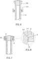
Fig. 8 is a partial enlargement ofFig. 7 ; -
Figs. 9 and 10 are schematic diagrams showing assembling of a second preferable embodiment of the present invention; -
Fig. 11 is a stereogram of a third preferable embodiment of the present invention; -
Fig. 12 is a breakdown drawing of the third preferable embodiment of the present invention; -
Fig. 13 is a cross-sectional view of the third preferable embodiment of the present invention; -
Fig. 14 is a partial cross-sectional enlargement of the third preferable embodiment of the present invention; -
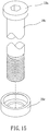
Fig. 15 is a breakdown drawing of a fourth preferable embodiment of the present invention; -
Fig. 16 is a cross-sectional view of the fourth preferable embodiment of the present invention; -
Fig. 17 is a partial cross-sectional enlargement of the fourth preferable embodiment of the present invention; -
Fig. 18 is a breakdown drawing of a fifth preferable embodiment of the present invention; -
Fig. 19 is a cross-sectional view of the fifth preferable embodiment of the present invention; -
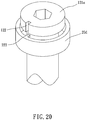
Fig. 20 is a stereogram of the fifth preferable embodiment of the present invention; -
Fig. 21 is a stereogram of a sixth preferable embodiment of the present invention; -
Fig. 22 is a cross-sectional view of the sixth preferable embodiment of the present invention; -
Figs. 23 and 24 are schematic diagrams showing assembling of the sixth preferable embodiment of the present invention. - Please refer to
Figs. 1 to 8 for a first preferable embodiment of the present invention. Abicycle axle 1 of the present invention includes amandrel 10 and asleeve member 20. - The
mandrel 10 defines an axial direction A and includes anaxial rod 11 and ahead portion 12 radially protruding from an end of theaxial rod 11. Thesleeve member 20 is sleeved around thehead portion 12 and includes aflange 21 radially extending inwardly. One of theaxial rod 11 and thesleeve member 20 has anengaging portion 13 radially disposed thereon, theengaging portion 13 and theflange 21 are overlapped with thehead portion 12 in the axial direction A, and thesleeve member 20 is rotatably restricted to thehead portion 12 by theengaging portion 13. Therefore, thesleeve member 20 can be assembled to themandrel 10 and thebicycle axle 1 has a simple structure and is easy to be manufactured and assembled. - The
engaging portion 13 radially protrudes from theaxial rod 11 and axially spaced apart from thehead portion 12, and at least part of theflange 21 is located between thehead portion 12 and theengaging portion 13 and is abuttable against thehead portion 12 and theengaging portion 13 in the axial direction A. Specifically, theflange 21 and thehead portion 12 may be at least partially overlapped with, interfere with or contact theengaging portion 13 in the axial direction A, or be circumferentially abutted against theengaging portion 13. - The
engaging portion 13 includes at least oneengaging projection 131, and the at least part of theflange 21 is interferable with the at least oneengaging projection 131 in the axial direction A so that theflange 21 is abuttable against the at least oneengaging projection 131 to prevent thesleeve member 20 from being disassembled from theaxial rod 11. Each of the at least oneengaging projection 131 includes an inclined guidingsurface 132 located at a side remote from thehead portion 12 so that theflange 21 can be smoothly passed through each of the at least oneengaging projection 131 for easy assembling. In this embodiment, the at least oneengaging projection 131 is an annular projection integrally disposed on theaxial rod 11, and the annular projection has the inclined guidingsurface 132, which is easy to assemble and stably restricts thesleeve member 20. However, the at least one engaging projection may include a plurality of blocks or ribs which are spacingly disposed around the axial rod. - Preferably, at least one of two axially opposite sides of the inner circumferential surface of the
flange 21 has a guidingsurface 211 tilted outwardly for easy assembling. In this embodiment, a side of the inner circumferential surface of theflange 21 adjacent to thehead portion 12 has the guidingsurface 211 annularly disposed thereon, which can guide thesleeve member 20 without alignment. In other embodiments, the two axially opposite sides of the inner circumferential surface of the flange may have respective guiding surfaces, which is convenient for assembling or disassembling the sleeve member; the flange may include a plurality of said guiding surfaces spacingly disposed therearound. - The
axial rod 11 may be made of aluminum, and theengaging portion 13 preferably protrudes radially beyond and outer circumferential surface of theaxial rod 11 by 0.2mm to 0.5mm. Theengaging portion 13 is radially deformable so that theflange 21 is easy to pass through theengaging portion 13 without abrasion. Specifically, the inner circumferential surface of theflange 21 has alip 212 radially and inwardly protruding therefrom, and thelip 212 is located between thehead portion 12 and theengaging portion 13 and is interferable with thehead portion 12 and theengaging portion 13 in the axial direction A. Theflange 21 defines a penetratinghole 213 through which themandrel 10 penetrates. In the axial direction A, a distance between thehead portion 12 and theengaging portion 13 is larger than (preferably) or equal to a thickness of thelip 212 so that thesleeve member 20 can smoothly rotate relative to themandrel 10. Relative to an axle center of theaxial rod 11, a minimum diametric dimension of thepenetrating hole 213 is smaller than a maximum diametric dimension of theengaging portion 13 so that thelip 212 is stably restricted between theengaging portion 13 and thehead portion 12. In other embodiments, the minimum diametric dimension of the penetrating hole may be equal to the maximum diametric dimension of the engaging portion, and when the lip radially corresponds to the engaging portion, the lip is circumferentially abutted against the engaging portion and passes through the engaging portion so that the lip is not easy to detach from the engaging portion, which is convenient for assembling and disassembling. - The
head portion 12 and theaxial rod 11 are integrally formed of one piece so as to have good structural strength. An end of theaxial rod 11 opposite to thehead portion 12 has a threadedsegment 111 which is configured to be screwed with a nut. Each of two end surfaces of theaxial rod 11 has an assemblinghole 112, such as a hexagonal hole, which is configured to be assembled with a driving tool or wrench to rotate themandrel 10. - Please refer to
figures 9 and 10 for a second preferable embodiment of the present invention. Themandrel 10a further includes at least onegroove 14 disposed on an outer circumferential surface of theaxial rod 11a and at least one restrictingmember 15 received within the at least onegroove 14, and the at least one restrictingmember 15 has the engagingportion 13a and protrudes beyond the outer circumferential surface of theaxial rod 11a so as to restrict theflange 21a. In this embodiment, the at least onegroove 14 is an annular groove, and the at least one restrictingmember 15 is an O-ring. When thesleeve member 20a is assembled to themandrel 10a, the O-ring is abutted against theflange 21a and is radially deformed so that at least part of theflange 21a can pass through the O-ring, and then the O-ring elastically recovers and is stably abutted against and restricts theflange 21a. The O-ring is elastically deformable and has good structural strength. The at least one groove may include a plurality of recessions, and the at least one restricting member may include a plurality of projections received within the plurality of recessions; the at least one restricting member may be a C-shaped retainer which is radially deformable for easy assembling; the at least one restricting member may have other configurations according to material characteristics and various requirements. Preferably, the inner circumferential surface of theflange 21a has at least one engaging concave 214 radially recessed thereon, and the engagingportion 13a is embedded within the at least one engaging concave 214 so that thesleeve member 20a is stably assembled to themandrel 10a and is smoothly rotatable relative to themandrel 10a. In this embodiment, the at least one engaging concave 214 is an annular recession which is convenient to assemble without alignment. - Please refer to
figures 11 to 14 for a third preferable embodiment of the present invention. The engagingportion 13b is disposed on thesleeve member 20b and axially corresponds to theflange 21b, and at least part of the engagingportion 13b protrudes beyond thehead portion 12a in a direction away from theaxial rod 11b. Thehead portion 12a includes anend surface 121 axially facing away from theaxial rod 11b, and the engagingportion 13b is abuttable against theend surface 121 so as to prevent thesleeve member 20b from departing from thehead portion 12a. In this embodiment, the engagingportion 13b is an annular projection radially extending inwardly, and an outer diameter of thehead portion 12a is larger than an inner diameter of the annular projection for stable engagement. Preferably, the annular projection radially protrudes beyond an innercircumferential surface 23 of thesleeve member 20b by 0.4mm to 0.6mm; a thickness of the annular projection in the axial direction A is between 0.4mm to 0.6mm. Therefore, thehead portion 12a urges the annular projection to deform so as to directly assemble thesleeve member 20b to thehead portion 12a, and thesleeve member 20b is not easy to disassemble from thehead portion 12a and has preferable structural strength. However, the sleeve member without the annular projection may be sleeved around the head portion, and an end portion of the sleeve member is bent inwardly to form the engaging portion; the engaging portion may include a plurality of blocks spacingly disposed around the inner circumferential surface of the sleeve member. - Please refer to
figures 15 to 17 for a fourth preferable embodiment of the present invention. Thesleeve member 20c further includes a throughhole 24, and a diametric dimension of the throughhole 24 is gradually decreased (smoothly decreased, preferably) in a direction from theflange 21c toward the engagingportion 13c, which is convenient to assemble thesleeve member 20c. A difference between a maximum diameter and a minimum diameter of a reduced portion of the throughhole 24 is between 0.2mm to 0.4mm so that a distance between thesleeve member 20c and thehead portion 12a is gradually decreased until thesleeve member 20c and thehead portion 12a are abuttable against each other so as to restrict axial movement of thesleeve member 20c. Thesleeve member 20c and thehead portion 12a have an interval therebetween so that themandrel 10c and thesleeve member 20c are smoothly rotatable relative to each other. The engagingportion 13c includes aninclined blocking surface 221 which is adjacently connected to awall 241 of the throughhole 24, and theinclined blocking surface 221 is at least partially overlapped with thehead portion 12a in the axial direction A so as to prevent thesleeve member 20c from departing from thehead portion 12a. In other embodiments, the penetrating hole may have a fixed hole diametric dimension and the wall of the through hole and the inclined blocking surface are connected with each other, the outer circumferential surface of the head portion is abutted against the inclined blocking surface and tapered in a direction toward the axial rod, which is convenient to be sleeved with the sleeve member. - Please refer to
figures 18 to 20 for a fifth preferable embodiment of the present invention. Thehead portion 12b has afirst guiding portion 122, and the engagingportion 13d has asecond guiding portion 222 corresponding to thefirst guiding portion 122. When thefirst guiding portion 122 is aligned with thesecond guiding portion 222, thesleeve member 20d is movable relative to thehead portion 12b in the axial direction A so that thesleeve member 20d is replaceable and easy to be assembled. One of thefirst guiding portion 122 and thesecond guiding portion 222 is a guiding projection, and the other of thefirst guiding portion 122 and thesecond guiding portion 222 is a guiding recession. In this embodiment, thefirst guiding portion 122 is a guiding recession extending on the outer circumferential surface of thehead portion 12b along the axial direction A, thesecond guiding portion 222 is a guiding projection radially protruding inwardly, and the guiding projection is abuttable against theend surface 121a of thehead portion 12b so as to prevent thesleeve member 20d from departing from thehead portion 12b. In other embodiments, the first guiding portion may be the guiding projection, the second guiding portion may be the guiding recession, and the inner circumferential surface of the sleeve member has an annular groove within which the guiding projection is received. Preferably, when the mandrel is laterally moved relative to the sleeve member and abutted against the sleeve member, a maximum distance between the guiding recession and the inner circumferential surface of the sleeve member is equal to a distance that the guiding projection radially protruding beyond the inner circumferential surface of the sleeve member. Therefore, the sleeve member is detachable from the head portion only when the mandrel is laterally moved relative to the sleeve member and abutted against the sleeve member and the guiding recession is aligned with the guiding projection. - Please refer to
figures 21 to 24 for a sixth preferable embodiment of the present invention. Thehead portion 12c has an outer threadedportion 123, and the engagingportion 13e has an inner threadedportion 223 which is configured to be screwed with the outer threadedportion 123. The inner threadedportion 223 is rotated to pass through thehead portion 12c, and the inner threadedportion 223 and the outer threadedportion 123 interfere with each other in the axial direction A, which prevents thesleeve member 20e from departing from thehead portion 12c and is easy to assemble and disassemble. - Although particular embodiments of the invention have been described in detail for purposes of illustration, various modifications and enhancements may be made without departing from the spirit and scope of the invention. Accordingly, the invention is not to be limited except as by the appended claims.
Claims (15)
- A bicycle axle (1), including:a mandrel (10, 10a, 10b, 10c), defining an axial direction (A), including an axial rod (11, 11a, 11b) and a head portion (12, 12a, 12b, 12c) radially protruding from an end of the axial rod (11, 11a, 11b);a sleeve member (20, 20a, 20b, 20c, 20d, 20e), being sleeved around the head portion (12, 12a, 12b, 12c), including a flange (21, 21a, 21b, 21c) radially extending inwardly;wherein one of the axial rod (11, 11a, 11b) and the sleeve member (20, 20a, 20b, 20c, 20d, 20e) has an engaging portion (13, 13a, 13b, 13c, 13d, 13e) radially disposed thereon, the engaging portion (13, 13a, 13b, 13c, 13d, 13e) and the flange (21, 21a, 21b, 21c) are overlapped with the head portion (12, 12a, 12b, 12c) in the axial direction (A), and the sleeve member (20, 20a, 20b, 20c, 20d, 20e) is rotatably restricted to the head portion (12, 12a,12b, 12c) by the engaging portion (13, 13a, 13b, 13c, 13d, 13e).
- The bicycle axle (1) of claim 1, wherein the engaging portion (13, 13a) radially protrudes from the axial rod (11, 11a) and axially spaced apart from the head portion (12), at least part of the flange (21, 21a) is located between the head portion (12) and the engaging portion (13, 13a) and is abuttable against the head portion (12) and the engaging portion (13, 13a) in the axial direction (A).
- The bicycle axle (1) of claim 2, wherein the engaging portion (13) includes at least one engaging projection (131), the at least part of the flange (21) is interferable with the at least one engaging projection (131) in the axial direction (A).
- The bicycle axle (1) of claim 3, wherein each of the at least one engaging projection (131) includes an inclined guiding surface (132) located at a side remote from the head portion (12).
- The bicycle axle (1) of claim 2, wherein an inner circumferential surface of the flange (21) has a lip (212) radially and inwardly protruding therefrom, the lip (212) is located between the head portion (12) and the engaging portion (13) and is interferable with the head portion (12) and the engaging portion (13) in the axial direction (A).
- The bicycle axle (1) of claim 5, wherein the engaging portion (13) includes at least one engaging projection (131), at least part of the flange (21) is interferable with the at least one engaging projection (131) in the axial direction (A); the at least one engaging projection (131) is an annular projection disposed on the axial rod (11); the annular projection includes an inclined guiding surface (132) located at a side remote from the head portion (12); the engaging portion (13) protrudes radially beyond an outer circumferential surface of the axial rod (11) by 0.2mm to 0.5mm; at least one of two axially opposite sides of the inner circumferential surface of the flange (21) has a guiding surface (211) tilted outwardly; the flange (21) defines a penetrating hole (213) through which the mandrel (10) penetrates, in the axial direction (A), a distance between the head portion (12) and the engaging portion (13) is larger than or equal to a thickness of the lip (212), and relative to an axle center of the axial rod (11), a minimum diametric dimension of the penetrating hole (213) is smaller than a maximum diametric dimension of the engaging portion (13); an end of the axial rod (11) opposite to the head portion (12) has a threaded segment (111); each of two end surfaces of the axial rod has an assembling hole (112).
- The bicycle axle of claim 2, wherein the mandrel (10a) further includes at least one groove (14) disposed on an outer circumferential surface of the axial rod (11a) and at least one restricting member (15) received within the at least one groove (14), and the at least one restricting member (15) has the engaging portion (13a).
- The bicycle axle of claim 2, wherein an inner circumferential surface of the flange (21a) has at least one engaging concave (214) radially recessed thereon, and the engaging portion (13a) is embedded within the at least one engaging concave (214).
- The bicycle axle of claim 1, wherein the engaging portion (13b, 13c, 13d, 13e) is disposed on the sleeve member (20b, 20c, 20d, 20e) and axially corresponds to the flange (21b, 21c), and at least part of the engaging portion (13b, 13c, 13d, 13e) protrudes beyond the head portion (12a, 12b, 12c) in a direction away from the axial rod (11b).
- The bicycle axle of claim 9, wherein the head portion (12a, 12b, 12c) includes an end surface (121, 121a) axially facing away from the axial rod (11b), and the engaging portion (13b, 13c, 13d, 13e) is abuttable against the end surface (121, 121a).
- The bicycle axle of claim 9, wherein the engaging portion (13b) is an annular projection radially extending inwardly, and an outer diameter of the head portion (12a) is larger than an inner diameter of the annular projection.
- The bicycle axle of claim 11, wherein the head portion (12a) includes an end surface (121) axially facing away from the axial rod (11b), and the engaging portion (13b) is abuttable against the end surface (121); the annular projection radially protrudes beyond an inner circumferential surface (23) of the sleeve member (20b) by 0.4mm to 0.6mm; a thickness of the annular projection in the axial direction (A) is between 0.4mm to 0.6mm; the head portion (12a) integrally extends from the axial rod (11b); an end of the axial rod (11b) opposite to the head portion (12a) has a threaded segment (111); each of two end surface of the axial rod has an assembling hole (112).
- The bicycle axle of claim 9, wherein the sleeve member (20) further includes a through hole (24), and a diametric dimension of the through hole (24) is gradually decreased in a direction from the flange (21c) toward the engaging portion (13c).
- The bicycle axle of claim 13, wherein the engaging portion (13c) includes an inclined blocking surface (221) which is adjacently connected to a wall (241) of the through hole (24), and the inclined blocking surface (221) is at least partially overlapped with the head portion (12a) in the axial direction (A).
- The bicycle axle of claim 9, wherein the head portion (12b) has a first guiding portion (122), the engaging portion (13d) has a second guiding portion (222) corresponding to the first guiding portion (122), one of the first guiding portion (122) and the second guiding portion (222) is a guiding projection, and the other of the first guiding portion (122) and the second guiding portion (222) is a guiding recession; when the first guiding portion (122) is aligned with the second guiding portion (222), the sleeve member (20d) is movable relative to the head portion (12b) in the axial direction (A).
Applications Claiming Priority (2)
| Application Number | Priority Date | Filing Date | Title |
|---|---|---|---|
| TW108201352U TWM578243U (en) | 2019-01-28 | 2019-01-28 | Bicycle wheel axle |
| TW108203104U TWM580057U (en) | 2019-03-14 | 2019-03-14 | Bicycle shaft |
Publications (2)
| Publication Number | Publication Date |
|---|---|
| EP3686101A1 true EP3686101A1 (en) | 2020-07-29 |
| EP3686101B1 EP3686101B1 (en) | 2022-04-27 |
Family
ID=68392837
Family Applications (1)
| Application Number | Title | Priority Date | Filing Date |
|---|---|---|---|
| EP19206069.7A Active EP3686101B1 (en) | 2019-01-28 | 2019-10-29 | Bicycle axle |
Country Status (2)
| Country | Link |
|---|---|
| EP (1) | EP3686101B1 (en) |
| ES (1) | ES2916711T3 (en) |
Citations (6)
| Publication number | Priority date | Publication date | Assignee | Title |
|---|---|---|---|---|
| US6886894B2 (en) | 2003-02-27 | 2005-05-03 | Shimano, Inc. | Bicycle hub axle |
| FR2920343A1 (en) * | 2007-08-27 | 2009-03-06 | Lamellet Gilles Marin | Rapid assembling and disassembling device for front wheel axle of bicycle, has locking and unlocking bush co-operated with adjusting nut using locking system that locks bush on adjusting nut when bush is supported on support washer |
| US20100206021A1 (en) * | 2006-05-29 | 2010-08-19 | Michel Tribout | Bicycle parts anti-theft device |
| TWM531358U (en) | 2016-05-24 | 2016-11-01 | J D Components Co Ltd | Quick-release device |
| TWI573701B (en) * | 2015-05-22 | 2017-03-11 | Raphael Schlanger | Quick release skewer assmbly |
| TWM538906U (en) * | 2016-12-23 | 2017-04-01 | Ful Chee Ent Co Ltd | Improved structure of fixation shaft end |
-
2019
- 2019-10-29 EP EP19206069.7A patent/EP3686101B1/en active Active
- 2019-10-29 ES ES19206069T patent/ES2916711T3/en active Active
Patent Citations (6)
| Publication number | Priority date | Publication date | Assignee | Title |
|---|---|---|---|---|
| US6886894B2 (en) | 2003-02-27 | 2005-05-03 | Shimano, Inc. | Bicycle hub axle |
| US20100206021A1 (en) * | 2006-05-29 | 2010-08-19 | Michel Tribout | Bicycle parts anti-theft device |
| FR2920343A1 (en) * | 2007-08-27 | 2009-03-06 | Lamellet Gilles Marin | Rapid assembling and disassembling device for front wheel axle of bicycle, has locking and unlocking bush co-operated with adjusting nut using locking system that locks bush on adjusting nut when bush is supported on support washer |
| TWI573701B (en) * | 2015-05-22 | 2017-03-11 | Raphael Schlanger | Quick release skewer assmbly |
| TWM531358U (en) | 2016-05-24 | 2016-11-01 | J D Components Co Ltd | Quick-release device |
| TWM538906U (en) * | 2016-12-23 | 2017-04-01 | Ful Chee Ent Co Ltd | Improved structure of fixation shaft end |
Also Published As
| Publication number | Publication date |
|---|---|
| EP3686101B1 (en) | 2022-04-27 |
| ES2916711T3 (en) | 2022-07-05 |
Similar Documents
| Publication | Publication Date | Title |
|---|---|---|
| US11305579B2 (en) | Bicycle axle | |
| US9163655B2 (en) | Thrust nut | |
| TWI475171B (en) | Fluid coupling and retainer for fluid coupling | |
| US10793079B1 (en) | Assembling structure for vehicle carrying device | |
| US20190283221A1 (en) | Two-stage universal joint | |
| US20160023333A1 (en) | Tool Head with a Screw Positioning Sleeve | |
| US9587665B2 (en) | Screw fastener | |
| US9469157B2 (en) | Bicycle freecoaster hub | |
| US11260508B2 (en) | Torque socket tool | |
| EP3686101A1 (en) | Bicycle axle | |
| US8234952B2 (en) | Handgrip for handlebar | |
| US11208052B2 (en) | Assembling structure for vehicle carrying device | |
| US20200147762A1 (en) | Two-way retractable socket | |
| CN209833879U (en) | Bicycle axle | |
| US11446798B2 (en) | Torque tool | |
| US11898587B2 (en) | Torque-limiting nut | |
| JP2020153462A (en) | Bearing attachment structure | |
| US8250714B2 (en) | Handgrip for handlebar | |
| JP2010043690A (en) | Rolling bearing and bearing unit | |
| US20230078767A1 (en) | Universal joint | |
| US20170297183A1 (en) | Screwdriver bit assembly with a magnetic structure | |
| US11717947B2 (en) | Press tool | |
| US10676149B2 (en) | Vehicle wheel axle assembly | |
| TWM578243U (en) | Bicycle wheel axle | |
| US11767077B2 (en) | Quick release structure |
Legal Events
| Date | Code | Title | Description |
|---|---|---|---|
| PUAI | Public reference made under article 153(3) epc to a published international application that has entered the european phase |
Free format text: ORIGINAL CODE: 0009012 |
|
| STAA | Information on the status of an ep patent application or granted ep patent |
Free format text: STATUS: THE APPLICATION HAS BEEN PUBLISHED |
|
| AK | Designated contracting states |
Kind code of ref document: A1 Designated state(s): AL AT BE BG CH CY CZ DE DK EE ES FI FR GB GR HR HU IE IS IT LI LT LU LV MC MK MT NL NO PL PT RO RS SE SI SK SM TR |
|
| AX | Request for extension of the european patent |
Extension state: BA ME |
|
| STAA | Information on the status of an ep patent application or granted ep patent |
Free format text: STATUS: REQUEST FOR EXAMINATION WAS MADE |
|
| 17P | Request for examination filed |
Effective date: 20200915 |
|
| RBV | Designated contracting states (corrected) |
Designated state(s): AL AT BE BG CH CY CZ DE DK EE ES FI FR GB GR HR HU IE IS IT LI LT LU LV MC MK MT NL NO PL PT RO RS SE SI SK SM TR |
|
| STAA | Information on the status of an ep patent application or granted ep patent |
Free format text: STATUS: EXAMINATION IS IN PROGRESS |
|
| 17Q | First examination report despatched |
Effective date: 20210215 |
|
| TPAC | Observations filed by third parties |
Free format text: ORIGINAL CODE: EPIDOSNTIPA |
|
| RIC1 | Information provided on ipc code assigned before grant |
Ipc: B60B 35/04 20060101ALN20210914BHEP Ipc: B60B 35/00 20060101ALN20210914BHEP Ipc: B60B 27/02 20060101ALN20210914BHEP Ipc: B62K 25/02 20060101AFI20210914BHEP |
|
| GRAP | Despatch of communication of intention to grant a patent |
Free format text: ORIGINAL CODE: EPIDOSNIGR1 |
|
| STAA | Information on the status of an ep patent application or granted ep patent |
Free format text: STATUS: GRANT OF PATENT IS INTENDED |
|
| RIC1 | Information provided on ipc code assigned before grant |
Ipc: B60B 35/04 20060101ALN20211008BHEP Ipc: B60B 35/00 20060101ALN20211008BHEP Ipc: B60B 27/02 20060101ALN20211008BHEP Ipc: B62K 25/02 20060101AFI20211008BHEP |
|
| INTG | Intention to grant announced |
Effective date: 20211111 |
|
| GRAS | Grant fee paid |
Free format text: ORIGINAL CODE: EPIDOSNIGR3 |
|
| GRAA | (expected) grant |
Free format text: ORIGINAL CODE: 0009210 |
|
| STAA | Information on the status of an ep patent application or granted ep patent |
Free format text: STATUS: THE PATENT HAS BEEN GRANTED |
|
| AK | Designated contracting states |
Kind code of ref document: B1 Designated state(s): AL AT BE BG CH CY CZ DE DK EE ES FI FR GB GR HR HU IE IS IT LI LT LU LV MC MK MT NL NO PL PT RO RS SE SI SK SM TR |
|
| REG | Reference to a national code |
Ref country code: GB Ref legal event code: FG4D |
|
| REG | Reference to a national code |
Ref country code: CH Ref legal event code: EP |
|
| REG | Reference to a national code |
Ref country code: AT Ref legal event code: REF Ref document number: 1486766 Country of ref document: AT Kind code of ref document: T Effective date: 20220515 |
|
| REG | Reference to a national code |
Ref country code: DE Ref legal event code: R096 Ref document number: 602019014098 Country of ref document: DE |
|
| REG | Reference to a national code |
Ref country code: IE Ref legal event code: FG4D |
|
| REG | Reference to a national code |
Ref country code: ES Ref legal event code: FG2A Ref document number: 2916711 Country of ref document: ES Kind code of ref document: T3 Effective date: 20220705 |
|
| REG | Reference to a national code |
Ref country code: LT Ref legal event code: MG9D |
|
| REG | Reference to a national code |
Ref country code: NL Ref legal event code: MP Effective date: 20220427 |
|
| REG | Reference to a national code |
Ref country code: AT Ref legal event code: MK05 Ref document number: 1486766 Country of ref document: AT Kind code of ref document: T Effective date: 20220427 |
|
| PG25 | Lapsed in a contracting state [announced via postgrant information from national office to epo] |
Ref country code: NL Free format text: LAPSE BECAUSE OF FAILURE TO SUBMIT A TRANSLATION OF THE DESCRIPTION OR TO PAY THE FEE WITHIN THE PRESCRIBED TIME-LIMIT Effective date: 20220427 |
|
| PG25 | Lapsed in a contracting state [announced via postgrant information from national office to epo] |
Ref country code: SE Free format text: LAPSE BECAUSE OF FAILURE TO SUBMIT A TRANSLATION OF THE DESCRIPTION OR TO PAY THE FEE WITHIN THE PRESCRIBED TIME-LIMIT Effective date: 20220427 Ref country code: PT Free format text: LAPSE BECAUSE OF FAILURE TO SUBMIT A TRANSLATION OF THE DESCRIPTION OR TO PAY THE FEE WITHIN THE PRESCRIBED TIME-LIMIT Effective date: 20220829 Ref country code: NO Free format text: LAPSE BECAUSE OF FAILURE TO SUBMIT A TRANSLATION OF THE DESCRIPTION OR TO PAY THE FEE WITHIN THE PRESCRIBED TIME-LIMIT Effective date: 20220727 Ref country code: LT Free format text: LAPSE BECAUSE OF FAILURE TO SUBMIT A TRANSLATION OF THE DESCRIPTION OR TO PAY THE FEE WITHIN THE PRESCRIBED TIME-LIMIT Effective date: 20220427 Ref country code: HR Free format text: LAPSE BECAUSE OF FAILURE TO SUBMIT A TRANSLATION OF THE DESCRIPTION OR TO PAY THE FEE WITHIN THE PRESCRIBED TIME-LIMIT Effective date: 20220427 Ref country code: GR Free format text: LAPSE BECAUSE OF FAILURE TO SUBMIT A TRANSLATION OF THE DESCRIPTION OR TO PAY THE FEE WITHIN THE PRESCRIBED TIME-LIMIT Effective date: 20220728 Ref country code: FI Free format text: LAPSE BECAUSE OF FAILURE TO SUBMIT A TRANSLATION OF THE DESCRIPTION OR TO PAY THE FEE WITHIN THE PRESCRIBED TIME-LIMIT Effective date: 20220427 Ref country code: BG Free format text: LAPSE BECAUSE OF FAILURE TO SUBMIT A TRANSLATION OF THE DESCRIPTION OR TO PAY THE FEE WITHIN THE PRESCRIBED TIME-LIMIT Effective date: 20220727 Ref country code: AT Free format text: LAPSE BECAUSE OF FAILURE TO SUBMIT A TRANSLATION OF THE DESCRIPTION OR TO PAY THE FEE WITHIN THE PRESCRIBED TIME-LIMIT Effective date: 20220427 |
|
| PG25 | Lapsed in a contracting state [announced via postgrant information from national office to epo] |
Ref country code: RS Free format text: LAPSE BECAUSE OF FAILURE TO SUBMIT A TRANSLATION OF THE DESCRIPTION OR TO PAY THE FEE WITHIN THE PRESCRIBED TIME-LIMIT Effective date: 20220427 Ref country code: PL Free format text: LAPSE BECAUSE OF FAILURE TO SUBMIT A TRANSLATION OF THE DESCRIPTION OR TO PAY THE FEE WITHIN THE PRESCRIBED TIME-LIMIT Effective date: 20220427 Ref country code: LV Free format text: LAPSE BECAUSE OF FAILURE TO SUBMIT A TRANSLATION OF THE DESCRIPTION OR TO PAY THE FEE WITHIN THE PRESCRIBED TIME-LIMIT Effective date: 20220427 Ref country code: IS Free format text: LAPSE BECAUSE OF FAILURE TO SUBMIT A TRANSLATION OF THE DESCRIPTION OR TO PAY THE FEE WITHIN THE PRESCRIBED TIME-LIMIT Effective date: 20220827 |
|
| REG | Reference to a national code |
Ref country code: DE Ref legal event code: R097 Ref document number: 602019014098 Country of ref document: DE |
|
| PG25 | Lapsed in a contracting state [announced via postgrant information from national office to epo] |
Ref country code: SM Free format text: LAPSE BECAUSE OF FAILURE TO SUBMIT A TRANSLATION OF THE DESCRIPTION OR TO PAY THE FEE WITHIN THE PRESCRIBED TIME-LIMIT Effective date: 20220427 Ref country code: SK Free format text: LAPSE BECAUSE OF FAILURE TO SUBMIT A TRANSLATION OF THE DESCRIPTION OR TO PAY THE FEE WITHIN THE PRESCRIBED TIME-LIMIT Effective date: 20220427 Ref country code: RO Free format text: LAPSE BECAUSE OF FAILURE TO SUBMIT A TRANSLATION OF THE DESCRIPTION OR TO PAY THE FEE WITHIN THE PRESCRIBED TIME-LIMIT Effective date: 20220427 Ref country code: EE Free format text: LAPSE BECAUSE OF FAILURE TO SUBMIT A TRANSLATION OF THE DESCRIPTION OR TO PAY THE FEE WITHIN THE PRESCRIBED TIME-LIMIT Effective date: 20220427 Ref country code: DK Free format text: LAPSE BECAUSE OF FAILURE TO SUBMIT A TRANSLATION OF THE DESCRIPTION OR TO PAY THE FEE WITHIN THE PRESCRIBED TIME-LIMIT Effective date: 20220427 Ref country code: CZ Free format text: LAPSE BECAUSE OF FAILURE TO SUBMIT A TRANSLATION OF THE DESCRIPTION OR TO PAY THE FEE WITHIN THE PRESCRIBED TIME-LIMIT Effective date: 20220427 |
|
| PLBE | No opposition filed within time limit |
Free format text: ORIGINAL CODE: 0009261 |
|
| STAA | Information on the status of an ep patent application or granted ep patent |
Free format text: STATUS: NO OPPOSITION FILED WITHIN TIME LIMIT |
|
| PG25 | Lapsed in a contracting state [announced via postgrant information from national office to epo] |
Ref country code: AL Free format text: LAPSE BECAUSE OF FAILURE TO SUBMIT A TRANSLATION OF THE DESCRIPTION OR TO PAY THE FEE WITHIN THE PRESCRIBED TIME-LIMIT Effective date: 20220427 |
|
| 26N | No opposition filed |
Effective date: 20230130 |
|
| PG25 | Lapsed in a contracting state [announced via postgrant information from national office to epo] |
Ref country code: SI Free format text: LAPSE BECAUSE OF FAILURE TO SUBMIT A TRANSLATION OF THE DESCRIPTION OR TO PAY THE FEE WITHIN THE PRESCRIBED TIME-LIMIT Effective date: 20220427 Ref country code: MC Free format text: LAPSE BECAUSE OF FAILURE TO SUBMIT A TRANSLATION OF THE DESCRIPTION OR TO PAY THE FEE WITHIN THE PRESCRIBED TIME-LIMIT Effective date: 20220427 |
|
| REG | Reference to a national code |
Ref country code: BE Ref legal event code: MM Effective date: 20221031 |
|
| PG25 | Lapsed in a contracting state [announced via postgrant information from national office to epo] |
Ref country code: LU Free format text: LAPSE BECAUSE OF NON-PAYMENT OF DUE FEES Effective date: 20221029 |
|
| PG25 | Lapsed in a contracting state [announced via postgrant information from national office to epo] |
Ref country code: BE Free format text: LAPSE BECAUSE OF NON-PAYMENT OF DUE FEES Effective date: 20221031 |
|
| PG25 | Lapsed in a contracting state [announced via postgrant information from national office to epo] |
Ref country code: IE Free format text: LAPSE BECAUSE OF NON-PAYMENT OF DUE FEES Effective date: 20221029 |
|
| PG25 | Lapsed in a contracting state [announced via postgrant information from national office to epo] |
Ref country code: HU Free format text: LAPSE BECAUSE OF FAILURE TO SUBMIT A TRANSLATION OF THE DESCRIPTION OR TO PAY THE FEE WITHIN THE PRESCRIBED TIME-LIMIT; INVALID AB INITIO Effective date: 20191029 |
|
| PG25 | Lapsed in a contracting state [announced via postgrant information from national office to epo] |
Ref country code: CY Free format text: LAPSE BECAUSE OF FAILURE TO SUBMIT A TRANSLATION OF THE DESCRIPTION OR TO PAY THE FEE WITHIN THE PRESCRIBED TIME-LIMIT Effective date: 20220427 |
|
| PG25 | Lapsed in a contracting state [announced via postgrant information from national office to epo] |
Ref country code: MK Free format text: LAPSE BECAUSE OF FAILURE TO SUBMIT A TRANSLATION OF THE DESCRIPTION OR TO PAY THE FEE WITHIN THE PRESCRIBED TIME-LIMIT Effective date: 20220427 |
|
| PG25 | Lapsed in a contracting state [announced via postgrant information from national office to epo] |
Ref country code: MT Free format text: LAPSE BECAUSE OF FAILURE TO SUBMIT A TRANSLATION OF THE DESCRIPTION OR TO PAY THE FEE WITHIN THE PRESCRIBED TIME-LIMIT Effective date: 20220427 |
|
| PG25 | Lapsed in a contracting state [announced via postgrant information from national office to epo] |
Ref country code: BG Free format text: LAPSE BECAUSE OF FAILURE TO SUBMIT A TRANSLATION OF THE DESCRIPTION OR TO PAY THE FEE WITHIN THE PRESCRIBED TIME-LIMIT Effective date: 20220427 |
|
| PG25 | Lapsed in a contracting state [announced via postgrant information from national office to epo] |
Ref country code: BG Free format text: LAPSE BECAUSE OF FAILURE TO SUBMIT A TRANSLATION OF THE DESCRIPTION OR TO PAY THE FEE WITHIN THE PRESCRIBED TIME-LIMIT Effective date: 20220427 |
|
| REG | Reference to a national code |
Ref country code: CH Ref legal event code: U11 Free format text: ST27 STATUS EVENT CODE: U-0-0-U10-U11 (AS PROVIDED BY THE NATIONAL OFFICE) Effective date: 20251101 |
|
| PG25 | Lapsed in a contracting state [announced via postgrant information from national office to epo] |
Ref country code: TR Free format text: LAPSE BECAUSE OF FAILURE TO SUBMIT A TRANSLATION OF THE DESCRIPTION OR TO PAY THE FEE WITHIN THE PRESCRIBED TIME-LIMIT Effective date: 20220427 |
|
| PGFP | Annual fee paid to national office [announced via postgrant information from national office to epo] |
Ref country code: DE Payment date: 20251029 Year of fee payment: 7 |
|
| PGFP | Annual fee paid to national office [announced via postgrant information from national office to epo] |
Ref country code: GB Payment date: 20251020 Year of fee payment: 7 |
|
| PGFP | Annual fee paid to national office [announced via postgrant information from national office to epo] |
Ref country code: IT Payment date: 20251027 Year of fee payment: 7 |
|
| PGFP | Annual fee paid to national office [announced via postgrant information from national office to epo] |
Ref country code: FR Payment date: 20251027 Year of fee payment: 7 |
|
| PGFP | Annual fee paid to national office [announced via postgrant information from national office to epo] |
Ref country code: CH Payment date: 20251101 Year of fee payment: 7 |
|
| PGFP | Annual fee paid to national office [announced via postgrant information from national office to epo] |
Ref country code: ES Payment date: 20251103 Year of fee payment: 7 |