EP3686057A1 - In-vehicle apparatus, data processing method, and data processing program - Google Patents
In-vehicle apparatus, data processing method, and data processing program Download PDFInfo
- Publication number
- EP3686057A1 EP3686057A1 EP20152800.7A EP20152800A EP3686057A1 EP 3686057 A1 EP3686057 A1 EP 3686057A1 EP 20152800 A EP20152800 A EP 20152800A EP 3686057 A1 EP3686057 A1 EP 3686057A1
- Authority
- EP
- European Patent Office
- Prior art keywords
- pulse
- unit
- ethernet avb
- output
- warning sound
- Prior art date
- Legal status (The legal status is an assumption and is not a legal conclusion. Google has not performed a legal analysis and makes no representation as to the accuracy of the status listed.)
- Granted
Links
Images


Classifications
-
- H—ELECTRICITY
- H04—ELECTRIC COMMUNICATION TECHNIQUE
- H04L—TRANSMISSION OF DIGITAL INFORMATION, e.g. TELEGRAPHIC COMMUNICATION
- H04L69/00—Network arrangements, protocols or services independent of the application payload and not provided for in the other groups of this subclass
- H04L69/28—Timers or timing mechanisms used in protocols
-
- G—PHYSICS
- G08—SIGNALLING
- G08B—SIGNALLING SYSTEMS, e.g. PERSONAL CALLING SYSTEMS; ORDER TELEGRAPHS; ALARM SYSTEMS
- G08B3/00—Audible signalling systems, e.g. audible personal calling systems
- G08B3/10—Audible signalling systems, e.g. audible personal calling systems using electric transmission; using electromagnetic transmission
-
- H—ELECTRICITY
- H04—ELECTRIC COMMUNICATION TECHNIQUE
- H04N—PICTORIAL COMMUNICATION, e.g. TELEVISION
- H04N21/00—Selective content distribution, e.g. interactive television or video on demand [VOD]
- H04N21/40—Client devices specifically adapted for the reception of or interaction with content, e.g. set-top-box [STB]; Operations thereof
- H04N21/41—Structure of client; Structure of client peripherals
- H04N21/414—Specialised client platforms, e.g. receiver in car or embedded in a mobile appliance
- H04N21/41422—Specialised client platforms, e.g. receiver in car or embedded in a mobile appliance located in transportation means, e.g. personal vehicle
-
- B—PERFORMING OPERATIONS; TRANSPORTING
- B60—VEHICLES IN GENERAL
- B60R—VEHICLES, VEHICLE FITTINGS, OR VEHICLE PARTS, NOT OTHERWISE PROVIDED FOR
- B60R16/00—Electric or fluid circuits specially adapted for vehicles and not otherwise provided for; Arrangement of elements of electric or fluid circuits specially adapted for vehicles and not otherwise provided for
- B60R16/02—Electric or fluid circuits specially adapted for vehicles and not otherwise provided for; Arrangement of elements of electric or fluid circuits specially adapted for vehicles and not otherwise provided for electric constitutive elements
-
- H—ELECTRICITY
- H04—ELECTRIC COMMUNICATION TECHNIQUE
- H04B—TRANSMISSION
- H04B1/00—Details of transmission systems, not covered by a single one of groups H04B3/00 - H04B13/00; Details of transmission systems not characterised by the medium used for transmission
- H04B1/69—Spread spectrum techniques
- H04B1/7163—Spread spectrum techniques using impulse radio
- H04B1/71635—Transmitter aspects
-
- H—ELECTRICITY
- H04—ELECTRIC COMMUNICATION TECHNIQUE
- H04L—TRANSMISSION OF DIGITAL INFORMATION, e.g. TELEGRAPHIC COMMUNICATION
- H04L65/00—Network arrangements, protocols or services for supporting real-time applications in data packet communication
- H04L65/1066—Session management
- H04L65/1069—Session establishment or de-establishment
-
- H—ELECTRICITY
- H04—ELECTRIC COMMUNICATION TECHNIQUE
- H04L—TRANSMISSION OF DIGITAL INFORMATION, e.g. TELEGRAPHIC COMMUNICATION
- H04L65/00—Network arrangements, protocols or services for supporting real-time applications in data packet communication
- H04L65/60—Network streaming of media packets
- H04L65/65—Network streaming protocols, e.g. real-time transport protocol [RTP] or real-time control protocol [RTCP]
-
- H—ELECTRICITY
- H04—ELECTRIC COMMUNICATION TECHNIQUE
- H04L—TRANSMISSION OF DIGITAL INFORMATION, e.g. TELEGRAPHIC COMMUNICATION
- H04L67/00—Network arrangements or protocols for supporting network services or applications
- H04L67/01—Protocols
- H04L67/12—Protocols specially adapted for proprietary or special-purpose networking environments, e.g. medical networks, sensor networks, networks in vehicles or remote metering networks
-
- H—ELECTRICITY
- H04—ELECTRIC COMMUNICATION TECHNIQUE
- H04N—PICTORIAL COMMUNICATION, e.g. TELEVISION
- H04N21/00—Selective content distribution, e.g. interactive television or video on demand [VOD]
- H04N21/40—Client devices specifically adapted for the reception of or interaction with content, e.g. set-top-box [STB]; Operations thereof
- H04N21/41—Structure of client; Structure of client peripherals
- H04N21/426—Internal components of the client ; Characteristics thereof
-
- H—ELECTRICITY
- H04—ELECTRIC COMMUNICATION TECHNIQUE
- H04N—PICTORIAL COMMUNICATION, e.g. TELEVISION
- H04N21/00—Selective content distribution, e.g. interactive television or video on demand [VOD]
- H04N21/40—Client devices specifically adapted for the reception of or interaction with content, e.g. set-top-box [STB]; Operations thereof
- H04N21/43—Processing of content or additional data, e.g. demultiplexing additional data from a digital video stream; Elementary client operations, e.g. monitoring of home network or synchronising decoder's clock; Client middleware
- H04N21/439—Processing of audio elementary streams
-
- H—ELECTRICITY
- H04—ELECTRIC COMMUNICATION TECHNIQUE
- H04N—PICTORIAL COMMUNICATION, e.g. TELEVISION
- H04N21/00—Selective content distribution, e.g. interactive television or video on demand [VOD]
- H04N21/40—Client devices specifically adapted for the reception of or interaction with content, e.g. set-top-box [STB]; Operations thereof
- H04N21/45—Management operations performed by the client for facilitating the reception of or the interaction with the content or administrating data related to the end-user or to the client device itself, e.g. learning user preferences for recommending movies, resolving scheduling conflicts
- H04N21/462—Content or additional data management e.g. creating a master electronic programme guide from data received from the Internet and a Head-end or controlling the complexity of a video stream by scaling the resolution or bit-rate based on the client capabilities
- H04N21/4622—Retrieving content or additional data from different sources, e.g. from a broadcast channel and the Internet
-
- H—ELECTRICITY
- H04—ELECTRIC COMMUNICATION TECHNIQUE
- H04R—LOUDSPEAKERS, MICROPHONES, GRAMOPHONE PICK-UPS OR LIKE ACOUSTIC ELECTROMECHANICAL TRANSDUCERS; ELECTRIC HEARING AIDS; PUBLIC ADDRESS SYSTEMS
- H04R3/00—Circuits for transducers
- H04R3/12—Circuits for transducers for distributing signals to two or more loudspeakers
-
- H—ELECTRICITY
- H04—ELECTRIC COMMUNICATION TECHNIQUE
- H04R—LOUDSPEAKERS, MICROPHONES, GRAMOPHONE PICK-UPS OR LIKE ACOUSTIC ELECTROMECHANICAL TRANSDUCERS; ELECTRIC HEARING AIDS; PUBLIC ADDRESS SYSTEMS
- H04R2499/00—Aspects covered by H04R or H04S not otherwise provided for in their subgroups
- H04R2499/10—General applications
- H04R2499/13—Acoustic transducers and sound field adaptation in vehicles
Definitions
- the present invention relates to an in-vehicle apparatus, a data processing method, and a data processing program.
- an amplifier functioning as an Ethernet Audio Video Bridging (AVB) listener is known.
- the amplifier outputs audio data after receiving an Ethernet AVB stream from a head unit and starting to generate a pulse for audio data playback.
- AVB Ethernet Audio Video Bridging
- the amplifier is configured to output a warning sound in addition to audio data, and is required to output the warning sound at the time of startup, the amplifier would not be able to immediately output the warning sound.
- an in-vehicle apparatus includes a first pulse generating unit configured to generate a first pulse in accordance with predetermined equipment before a data stream transmitted from the equipment is received; a second pulse generating unit configured to generate a second pulse based on the received data stream; an output unit configured to output a warning sound based on the first pulse or the second pulse; and a switching unit configured to output the first pulse to the output unit before the data stream is received, and output the second pulse to the output unit as of when the first pulse and the second pulse coincide.
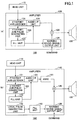
- FIGS. 1 are diagrams illustrating configurations of in-vehicle apparatuses according to comparative examples
- a configuration of an in-vehicle apparatus (amplifier) according to a first embodiment will be described.
- configurations of in-vehicle apparatuses (amplifiers) according to comparative examples will be described first, and the configuration of the in-vehicle apparatus (amplifier) according to the first embodiment will be described next.
- FIGS. 1 are diagrams illustrating the configurations of the in-vehicle apparatuses according to the comparative examples.
- An in-vehicle system 100 illustrated in FIG. 1 (a) includes an amplifier 120 configured to output audio data after receiving an Ethernet AVB stream (an example of a data stream) and starting to generate a pulse for audio data playback at the time of startup. First, the in-vehicle system 100 illustrated in FIG. 1 (a) will be described.
- the in-vehicle system 100 includes a head unit 110, the amplifier 120, and a speaker 130.
- the head unit 110 is predetermined equipment that serves as an Ethernet AVB talker and transmits an Ethernet AVB stream including audio data.
- the amplifier 120 includes an Ethernet AVB listener 121, an Ethernet AVB pulse generating unit 122, a pulse-locked loop (PLL) unit 123, an audio interface (I/F) unit 124, a combining unit 125, and a warning sound signal output unit 126.
- Ethernet AVB listener 121 an Ethernet AVB pulse generating unit 122
- PLL pulse-locked loop
- I/F audio interface
- combining unit 125 a combining unit 125
- warning sound signal output unit 126 includes an Ethernet AVB listener 121, an Ethernet AVB pulse generating unit 122, a pulse-locked loop (PLL) unit 123, an audio interface (I/F) unit 124, a combining unit 125, and a warning sound signal output unit 126.
- PLL pulse-locked loop
- I/F audio interface
- the Ethernet AVB listener 121 performs Ethernet link-up and gPTP time synchronization processes, and receives the Ethernet AVB stream from the head unit 110. Further, the Ethernet AVB listener 121 performs a process for acquiring definition information on a start time and an end time of the Ethernet AVB stream. The Ethernet AVB listener 121 instructs the Ethernet AVB pulse generating unit 122 to start to generate a pulse, and indicates audio data included in the Ethernet AVB stream to the audio I/F unit 124.
- the Ethernet AVB pulse generating unit 122 is an example of a second pulse generating unit. In response to receiving an instruction from the Ethernet AVB listener 121, the Ethernet AVB pulse generating unit 122 starts to generate an Ethernet AVB pulse (second pulse) based on the Ethernet AVB stream.
- the PLL unit 123 controls the audio I/F unit 124 and the warning sound signal output unit 126 such that the audio I/F unit 124 and the warning sound signal output unit 126 output audio data and a warning sound in synchronization with the Ethernet AVB pulse generated by the Ethernet AVB pulse generating unit 122.
- the audio I/F unit 124 outputs audio data, indicated by the Ethernet AVB listener 121, based on the Ethernet AVB pulse.
- the warning sound signal output unit 126 is an example of an output unit, and outputs the warning sound based on the Ethernet AVB pulse if a command is received from an external device.
- the combining unit 125 combines the audio data output from the audio I/F unit 124 with the warning sound output from the warning sound signal output unit 126, and outputs the combined audio data and the warning sound to the speaker 130. Then, the speaker 130 outputs the combined audio data and the warning sound.
- the warning sound signal output unit 126 of the amplifier 120 is configured to output the warning sound based on the Ethernet AVB pulse. For this reason, if the command is received from the external device at startup of the amplifier 120, the warning sound would be unable to be output for a period of time before the Ethernet AVB pulse starts to be generated.
- An in-vehicle system 100' illustrated in FIG. 1 (b) includes an amplifier 140 configured to output a warning sound based on a local pulse, instead of outputting the warning sound based on an Ethernet AVB pulse.
- the amplifier 140 includes an asynchronous sample rate converter (ASRC) 141, a local pulse generating unit 142, and a PLL unit 143.
- ASRC asynchronous sample rate converter
- the local pulse generating unit 142 generates a local pulse (first pulse) for output of a warning sound.
- the PLL unit 143 controls the warning sound signal output unit 126 such that the warning sound signal output unit 126 outputs the warning sound in synchronization with the local pulse generated by the local pulse generating unit 142.
- the ASRC 141 performs a process in which audio data output from the audio I/F unit 124 based on the Ethernet AVB pulse is synchronized with the warning sound output from the warning sound signal output unit 126.
- the warning sound signal output unit 126 of the amplifier 140 is configured to output the warning sound based on the local pulse. Therefore, it is possible to avoid a situation in which the warning sound is unable to be output for a period of time before the Ethernet AVB pulse starts to be generated at startup of the amplifier 140, as in the case of the in-vehicle system 100 illustrated in FIG. 1 (a) .
- the ASRC 141 is required to be additionally included in the amplifier 140, thus resulting in an increase in costs. Further, in the in-vehicle system 100' illustrated in FIG. 1 (b) , binary data is unable to be output.
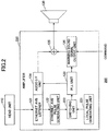
- FIG. 2 is a diagram illustrating an example of the configuration of the in-vehicle apparatus according to the first embodiment.
- An in-vehicle system 200 illustrated in FIG. 2 differs from the in-vehicle systems 100 and 100' illustrated in FIGS. 1 , in that an amplifier 220 includes a local pulse generating unit 221, and a switching unit 222.
- the local pulse generating unit 221 is an example of a first pulse generating unit and generates a local pulse in accordance with the head unit 110.
- the local pulse generating unit 221 generates a local pulse during startup of the amplifier 220.
- the switching unit 222 outputs the local pulse generated by the local pulse generating unit 221 to the PLL unit 123 during the startup of the amplifier 220. Further, the switching unit 222 switches pulses to be output to the PLL unit 123, at a timing when the local pulse generated by the local pulse generating unit 221 coincides with an Ethernet AVB pulse generated by the Ethernet AVB pulse generating unit 122. Specifically, the switching unit 222 switches from the local pulse to the Ethernet AVB pulse, and outputs the Ethernet AVB pulse to the PLL unit 123.
- the warning sound signal output unit 126 outputs the warning sound based on the local pulse instead of the Ethernet AVB pulse. Therefore, it is possible to avoid a situation in which the warning sound is unable to be output for a period of time before the Ethernet AVB pulse starts to be generated at the startup of the amplifier 120, as in the in-vehicle system 100 illustrated in FIG. 1 (a) . Namely, it is possible to shorten the time before starting to output the warning sound at the startup of the amplifier 220.
- the in-vehicle apparatus (amplifier 220) according to the first embodiment, as of when the Ethernet AVB pulse starts to be generated and the generated Ethernet AVB pulse coincides with the local pulse, audio data and the warning sound are output based on the Ethernet AVB pulse. Therefore, the ASRC 141 is not required to be additionally included in the amplifier, thereby avoiding an increase in costs.
- binary data can also be output.
- FIG. 3 is a diagram illustrating pulse flows in the in-vehicle apparatus according to the first embodiment.
- a thick dashed arrow I indicates a pulse flow at startup of the amplifier 220.
- the local pulse generating unit 221 starts to generate a local pulse
- the switching unit 222 outputs the local pulse generated by the local pulse generating unit 221 to the PLL unit 123.
- the warning sound signal output unit 126 can output the warning sound based on the local pulse if a command is received from an external device.
- thick dashed arrows II indicate pulse flows after an Ethernet AVB stream is transmitted from the head unit 110 and the Ethernet AVB pulse is started to be generated by the Ethernet AVB pulse generating unit 122.
- the switching unit 222 switches from the local pulse to the Ethernet AVB pulse generated by the Ethernet AVB pulse generating unit 122, and outputs the Ethernet AVB pulse to the PLL unit 123.
- the audio I/F unit 124 outputs audio data based on the Ethernet AVB pulse. Further, if the command is received from the external device, the warning sound signal output unit 126 outputs the warning sound based on the Ethernet AVB pulse.
- FIG. 4 is a flowchart illustrating the flow of the audio data process performed by the in-vehicle apparatus according to the first embodiment. By starting the amplifier 220, the audio data process illustrated in FIG. 4 starts.
- step S401 the local pulse generating unit 221 starts to generate a local pulse.
- step S402 the warning sound signal output unit 126 determines whether a command has been received from an external device. In step S402, when the warning sound signal output unit 126 determines that the command has not been received (no in step S402), the process proceeds to step S404.
- step S402 when the warning sound signal output unit 126 determines that the command has been received (yes in step S402), the process proceeds to step S403.
- step S403 the warning sound signal output unit 126 outputs a warning sound based on the local pulse.
- step S404 the Ethernet AVB listener 121 determines whether an Ethernet AVB stream has been received from the head unit 110. In step S404, when the Ethernet AVB listener determines that the Ethernet AVB stream has not been received (no in step S404), the process returns to step S402. Note that Ethernet link-up and gPTP time synchronization processes are assumed to be completed at this point.
- step S404 when the Ethernet AVB listener determines that the Ethernet AVB stream has been received (yes in step S404), a process for acquiring definition information on a start time and an end time of the Ethernet AVB stream is performed. Then, the process proceeds to step S405.
- step S405 the Ethernet AVB pulse generating unit 122 starts to generate an Ethernet AVB pulse.
- step S406 the switching unit 222 determines whether the local pulse generated by the local pulse generating unit 221 coincides with the Ethernet AVB pulse generated by the Ethernet AVB pulse generating unit 122.
- step S406 when it is determined that the local pulse and the Ethernet AVB pulse do not coincide (no in step S406), the process proceeds to step S407.
- step S407 the audio I/F unit 124 outputs audio data based on the local pulse.
- step S408 the warning sound signal output unit 126 determines whether the command has been received from the external device. In step S408, when it is determined that the command has not been received (no in step S408), the process returns to step S406.
- step S408 when it is determined that the command has been received (yes in step S408), the process proceeds to step S409.
- step S409 the warning sound signal output unit 126 outputs the warning sound based on the local pulse.
- step S406 when it is determined that the local pulse and the Ethernet AVB pulse coincide (yes in step S406), the process proceeds to step S410.
- step S410 the switching unit 222 switches from the local pulse to the Ethernet AVB pulse, and outputs the Ethernet AVB pulse to the PLL unit 123. Therefore, the audio I/F unit 124 outputs audio data based on the Ethernet AVB pulse. Note that, after the switching unit 222 switches to the Ethernet AVB pulse, the local pulse generating unit 221 stops the generation of the local pulse.
- step S411 the warning sound signal output unit 126 determines whether the command has been received from the external device. In step S411, when it is determined that the command has not been received (no in step S411), the process proceeds to step S413.
- step S411 when it is determined that the command has been received (yes in step S411), the process proceeds to step S412.
- step S412 the warning sound signal output unit 126 outputs the warning sound based on the Ethernet AVB pulse.
- step S413 the Ethernet AVB listener 121 determines whether to continue the audio data process. In step S413, when the Ethernet AVB listener 121 determines to continue the audio data process (yes in step S413), the process returns to step S410.
- step S413 when the Ethernet AVB listener 121 determines not to continue the audio data process (no in step S413), the audio data process ends.
- the in-vehicle apparatus includes:
- the in-vehicle apparatus it is possible to output the warning sound based on the local pulse at startup, thereby avoiding a situation in which the warning sound is unable to be output for a period of time before the Ethernet AVB pulse starts to be generated. Namely, at startup of the in-vehicle apparatus, it is possible to shorten the time required before starting to output the warning sound.
- audio data and the warning sound are output based on the Ethernet AVB pulse as of when the switching unit switches to the Ethernet AVB pulse.
- the transmission of the Ethernet AVB stream may be interrupted.
- the Ethernet AVB pulse generating unit stops the generation of the Ethernet AVB pulse.
- the warning sound signal output unit 126 would not be able to output the warning sound.
- a local pulse generating unit 522 resumes the generation of the local pulse, and the warning sound signal output unit outputs the warning sound based on the local pulse.
- FIG. 5 is a diagram illustrating an example of the configuration of the in-vehicle apparatus and pulse flows according to the second embodiment.
- functions of an Ethernet AVB pulse generating unit 521, functions of the local pulse generating unit 522, and functions of a switching unit 523 included in an amplifier 520 are different from those of the in-vehicle system illustrated in FIG. 2 .
- the Ethernet AVB pulse generating unit 521 has a function to monitor whether the transmission of the Ethernet AVB stream from the head unit 110 is interrupted.
- Ethernet AVB pulse generating unit 521 also has a function to send a notification to the local pulse generating unit 522 and the switching unit 523 when it is determined that the transmission of the Ethernet AVB stream is interrupted.
- the local pulse generating unit 522 has a function to resume the generation of the local pulse at a timing when the local pulse is synchronized with the Ethernet AVB pulse based on the notification from the Ethernet AVB pulse generating unit 521.
- the switching unit 523 has a function to switch from the Ethernet AVB pulse to the local pulse based on the notification from the Ethernet AVB pulse generating unit 521, and outputs the local pulse to the PLL unit 123. Therefore, if the command is received from the external device, the warning sound signal output unit 126 outputs the warning sound based on the local pulse, started to be generated again by the local pulse generating unit 522 (see a thick dashed arrow III).
- FIG. 6 is a flowchart illustrating the flow of the audio data process performed by the in-vehicle apparatus according to the second embodiment.
- the differences between the audio data process illustrated in FIG. 6 and the audio data process illustrated in FIG. 4 are step S601 and step S602.
- step S601 the Ethernet AVB pulse generating unit 521 determines whether the transmission of the Ethernet AVB stream from the head unit 110 is interrupted. In step S601, when the transmission of the Ethernet AVB stream is determined not to be interrupted (no in step S601), the process proceeds to step S413.
- step S601 Conversely, when the transmission of the Ethernet AVB stream is determined to be interrupted (yes in step S601), the process proceeds to step S602.
- step S602 the local pulse generating unit 522 resumes the generation of the local pulse at a timing when the local pulse is synchronized with the Ethernet AVB pulse, and the process returns to step S402.
- the Ethernet AVB pulse generating unit 521 monitors whether the transmission of the Ethernet AVB stream is interrupted after the switching unit switches to the Ethernet AVB stream, and the local pulse generating unit resumes the generation of the local pulse when the transmission of the Ethernet AVB stream is determined to be interrupted, and the warning sound signal output unit outputs the warning sound based on the local pulse.
- the functions of the amplifier 220 and the amplifier 520 are implemented by hardware. However, some of the functions of the amplifier 220 and the amplifier 520 may be implemented by software. Specifically, some of the functions of the amplifier 220 and the amplifier 520 may be implemented by causing a computer to execute a data processing program.
- the data processing program, or data processing program product may comprise instructions which, when the instructions or program are executed by the computer, cause the computer to execute a process as described herein.
- the computer may be configured by a central processing unit (CPU), a read-only memory (ROM), and a random-access memory (RAM).
- each of the amplifier 220 and the amplifier 520 is illustrated as an individual in-vehicle apparatus, but may be provided as a part of another in-vehicle apparatus.
Landscapes
- Engineering & Computer Science (AREA)
- Signal Processing (AREA)
- Multimedia (AREA)
- Computer Networks & Wireless Communication (AREA)
- Physics & Mathematics (AREA)
- Databases & Information Systems (AREA)
- General Health & Medical Sciences (AREA)
- Health & Medical Sciences (AREA)
- Electromagnetism (AREA)
- General Physics & Mathematics (AREA)
- Computer Security & Cryptography (AREA)
- Computing Systems (AREA)
- Medical Informatics (AREA)
- Mechanical Engineering (AREA)
- Otolaryngology (AREA)
- Acoustics & Sound (AREA)
- Business, Economics & Management (AREA)
- General Business, Economics & Management (AREA)
- Small-Scale Networks (AREA)
- Emergency Alarm Devices (AREA)
Abstract
Description
- The present invention relates to an in-vehicle apparatus, a data processing method, and a data processing program.
- Conventionally, as an in-vehicle apparatus connected to a network via Ethernet (registered trademark), an amplifier functioning as an Ethernet Audio Video Bridging (AVB) listener is known. The amplifier outputs audio data after receiving an Ethernet AVB stream from a head unit and starting to generate a pulse for audio data playback.
- [Patent Document 1] Japanese Laid-Open Patent Publication No.
2004-282441 - [Patent Document 2] Japanese Laid-Open Patent Publication No.
2013-90187 - [Patent Document3] Japanese Laid-Open Patent Publication No.
2017-163322 - In the above-described amplifier, various processes, including Ethernet link-up, gPTP (generalized precision time protocol) time synchronization, and acquisition of definition information on a start time and an end time of an Ethernet AVB stream, are performed at startup of the amplifier. Therefore, it takes a certain period of time before a pulse for audio data playback starts to be generated and audio data is output.
- Thus, if the amplifier is configured to output a warning sound in addition to audio data, and is required to output the warning sound at the time of startup, the amplifier would not be able to immediately output the warning sound.
- In view of the above-described problem, it is a general object of the present invention to shorten the time required before starting to output a warning sound at startup of an in-vehicle apparatus.
- The invention relates to an in-vehicle apparatus, a method and a data processing program according to the appended claims. Embodiments are disclosed in the dependent claims. According to one aspect, an in-vehicle apparatus includes a first pulse generating unit configured to generate a first pulse in accordance with predetermined equipment before a data stream transmitted from the equipment is received; a second pulse generating unit configured to generate a second pulse based on the received data stream; an output unit configured to output a warning sound based on the first pulse or the second pulse; and a switching unit configured to output the first pulse to the output unit before the data stream is received, and output the second pulse to the output unit as of when the first pulse and the second pulse coincide.
- It is possible to shorten the time required before starting to output a warning sound at startup of an in-vehicle apparatus.
-
FIGS. 1 are diagrams illustrating configurations of in-vehicle apparatuses according to comparative examples; -
FIG. 2 is a diagram illustrating an example of a configuration of an in-vehicle apparatus according to a first embodiment; -
FIG. 3 is a diagram illustrating pulse flows in the in-vehicle apparatus according to the first embodiment; -
FIG. 4 is a flowchart illustrating a flow of an audio data process performed by the in-vehicle apparatus according to the first embodiment; -
FIG. 5 is a diagram illustrating an example of a configuration of an in-vehicle apparatus and pulse flows according to a second embodiment; and -
FIG. 6 is a flowchart illustrating a flow of an audio data process performed by the in-vehicle apparatus according to the second embodiment. - In the following, embodiments of the present invention will be described with reference to the accompanying drawings. In the specification and drawings, elements having substantially the same functions or configurations are denoted by the same numerals, and a duplicate description thereof will not be provided.
- A configuration of an in-vehicle apparatus (amplifier) according to a first embodiment will be described. In order to clarify the differences, configurations of in-vehicle apparatuses (amplifiers) according to comparative examples will be described first, and the configuration of the in-vehicle apparatus (amplifier) according to the first embodiment will be described next.
-
FIGS. 1 are diagrams illustrating the configurations of the in-vehicle apparatuses according to the comparative examples. An in-vehicle system 100 illustrated inFIG. 1 (a) includes anamplifier 120 configured to output audio data after receiving an Ethernet AVB stream (an example of a data stream) and starting to generate a pulse for audio data playback at the time of startup. First, the in-vehicle system 100 illustrated inFIG. 1 (a) will be described. - As illustrated in
FIG. 1 (a) , the in-vehicle system 100 includes ahead unit 110, theamplifier 120, and aspeaker 130. - The
head unit 110 is predetermined equipment that serves as an Ethernet AVB talker and transmits an Ethernet AVB stream including audio data. - The
amplifier 120 includes an EthernetAVB listener 121, an Ethernet AVBpulse generating unit 122, a pulse-locked loop (PLL)unit 123, an audio interface (I/F)unit 124, a combiningunit 125, and a warning soundsignal output unit 126. - The Ethernet
AVB listener 121 performs Ethernet link-up and gPTP time synchronization processes, and receives the Ethernet AVB stream from thehead unit 110. Further, the EthernetAVB listener 121 performs a process for acquiring definition information on a start time and an end time of the Ethernet AVB stream. The EthernetAVB listener 121 instructs the Ethernet AVBpulse generating unit 122 to start to generate a pulse, and indicates audio data included in the Ethernet AVB stream to the audio I/F unit 124. - The Ethernet AVB
pulse generating unit 122 is an example of a second pulse generating unit. In response to receiving an instruction from the EthernetAVB listener 121, the Ethernet AVBpulse generating unit 122 starts to generate an Ethernet AVB pulse (second pulse) based on the Ethernet AVB stream. - The
PLL unit 123 controls the audio I/F unit 124 and the warning soundsignal output unit 126 such that the audio I/F unit 124 and the warning soundsignal output unit 126 output audio data and a warning sound in synchronization with the Ethernet AVB pulse generated by the Ethernet AVBpulse generating unit 122. - The audio I/
F unit 124 outputs audio data, indicated by the EthernetAVB listener 121, based on the Ethernet AVB pulse. - The warning sound
signal output unit 126 is an example of an output unit, and outputs the warning sound based on the Ethernet AVB pulse if a command is received from an external device. - The combining
unit 125 combines the audio data output from the audio I/F unit 124 with the warning sound output from the warning soundsignal output unit 126, and outputs the combined audio data and the warning sound to thespeaker 130. Then, thespeaker 130 outputs the combined audio data and the warning sound. - As described above, in the in-
vehicle system 100, the warning soundsignal output unit 126 of theamplifier 120 is configured to output the warning sound based on the Ethernet AVB pulse. For this reason, if the command is received from the external device at startup of theamplifier 120, the warning sound would be unable to be output for a period of time before the Ethernet AVB pulse starts to be generated. - An in-vehicle system 100' illustrated in
FIG. 1 (b) includes anamplifier 140 configured to output a warning sound based on a local pulse, instead of outputting the warning sound based on an Ethernet AVB pulse. - Unlike the in-
vehicle system 100, in the in-vehicle system 100' illustrated inFIG. 1 (b) , theamplifier 140 includes an asynchronous sample rate converter (ASRC) 141, a localpulse generating unit 142, and aPLL unit 143. - The local
pulse generating unit 142 generates a local pulse (first pulse) for output of a warning sound. - The
PLL unit 143 controls the warning soundsignal output unit 126 such that the warning soundsignal output unit 126 outputs the warning sound in synchronization with the local pulse generated by the localpulse generating unit 142. - The ASRC 141 performs a process in which audio data output from the audio I/
F unit 124 based on the Ethernet AVB pulse is synchronized with the warning sound output from the warning soundsignal output unit 126. - As described above, in the in-vehicle system 100' illustrated in
FIG. 1B , the warning soundsignal output unit 126 of theamplifier 140 is configured to output the warning sound based on the local pulse. Therefore, it is possible to avoid a situation in which the warning sound is unable to be output for a period of time before the Ethernet AVB pulse starts to be generated at startup of theamplifier 140, as in the case of the in-vehicle system 100 illustrated inFIG. 1 (a) . - However, in the in-vehicle system 100' illustrated in
FIG. 1 (b) , the ASRC 141 is required to be additionally included in theamplifier 140, thus resulting in an increase in costs. Further, in the in-vehicle system 100' illustrated inFIG. 1 (b) , binary data is unable to be output. -
FIG. 2 is a diagram illustrating an example of the configuration of the in-vehicle apparatus according to the first embodiment. An in-vehicle system 200 illustrated inFIG. 2 differs from the in-vehicle systems 100 and 100' illustrated inFIGS. 1 , in that anamplifier 220 includes a localpulse generating unit 221, and aswitching unit 222. - The local
pulse generating unit 221 is an example of a first pulse generating unit and generates a local pulse in accordance with thehead unit 110. The localpulse generating unit 221 generates a local pulse during startup of theamplifier 220. - The
switching unit 222 outputs the local pulse generated by the localpulse generating unit 221 to thePLL unit 123 during the startup of theamplifier 220. Further, theswitching unit 222 switches pulses to be output to thePLL unit 123, at a timing when the local pulse generated by the localpulse generating unit 221 coincides with an Ethernet AVB pulse generated by the Ethernet AVBpulse generating unit 122. Specifically, theswitching unit 222 switches from the local pulse to the Ethernet AVB pulse, and outputs the Ethernet AVB pulse to thePLL unit 123. - After the
switching unit 222 switches the pulses, audio data and a warning sound are output based on the Ethernet AVB pulse. - Accordingly, in the in-vehicle apparatus (amplifier 220) according to the first embodiment, during the startup of the
amplifier 220, the warning soundsignal output unit 126 outputs the warning sound based on the local pulse instead of the Ethernet AVB pulse. Therefore, it is possible to avoid a situation in which the warning sound is unable to be output for a period of time before the Ethernet AVB pulse starts to be generated at the startup of theamplifier 120, as in the in-vehicle system 100 illustrated inFIG. 1 (a) . Namely, it is possible to shorten the time before starting to output the warning sound at the startup of theamplifier 220. - Further, in the in-vehicle apparatus (amplifier 220) according to the first embodiment, as of when the Ethernet AVB pulse starts to be generated and the generated Ethernet AVB pulse coincides with the local pulse, audio data and the warning sound are output based on the Ethernet AVB pulse. Therefore, the
ASRC 141 is not required to be additionally included in the amplifier, thereby avoiding an increase in costs. In addition, in the in-vehicle apparatus (amplifier 220) according to the first embodiment, binary data can also be output. - Next, functions of the
switching unit 222 will be described in further detail.FIG. 3 is a diagram illustrating pulse flows in the in-vehicle apparatus according to the first embodiment. InFIG. 3 , a thick dashed arrow I indicates a pulse flow at startup of theamplifier 220. By starting theamplifier 220, the localpulse generating unit 221 starts to generate a local pulse, and theswitching unit 222 outputs the local pulse generated by the localpulse generating unit 221 to thePLL unit 123. - Therefore, even if the Ethernet AVB
pulse generating unit 122 has not started to generate an Ethernet AVB pulse, the warning soundsignal output unit 126 can output the warning sound based on the local pulse if a command is received from an external device. - Further, in
FIG. 3 , thick dashed arrows II indicate pulse flows after an Ethernet AVB stream is transmitted from thehead unit 110 and the Ethernet AVB pulse is started to be generated by the Ethernet AVBpulse generating unit 122. - At a timing when the Ethernet AVB pulse and the local pulse coincide, the
switching unit 222 switches from the local pulse to the Ethernet AVB pulse generated by the Ethernet AVBpulse generating unit 122, and outputs the Ethernet AVB pulse to thePLL unit 123. - Then, the audio I/
F unit 124 outputs audio data based on the Ethernet AVB pulse. Further, if the command is received from the external device, the warning soundsignal output unit 126 outputs the warning sound based on the Ethernet AVB pulse. - Next, a flow of an audio data process performed by the in-vehicle apparatus (amplifier 220) will be described.
FIG. 4 is a flowchart illustrating the flow of the audio data process performed by the in-vehicle apparatus according to the first embodiment. By starting theamplifier 220, the audio data process illustrated inFIG. 4 starts. - In step S401, the local
pulse generating unit 221 starts to generate a local pulse. - In step S402, the warning sound
signal output unit 126 determines whether a command has been received from an external device. In step S402, when the warning soundsignal output unit 126 determines that the command has not been received (no in step S402), the process proceeds to step S404. - Conversely, in step S402, when the warning sound
signal output unit 126 determines that the command has been received (yes in step S402), the process proceeds to step S403. In step S403, the warning soundsignal output unit 126 outputs a warning sound based on the local pulse. - In step S404, the
Ethernet AVB listener 121 determines whether an Ethernet AVB stream has been received from thehead unit 110. In step S404, when the Ethernet AVB listener determines that the Ethernet AVB stream has not been received (no in step S404), the process returns to step S402. Note that Ethernet link-up and gPTP time synchronization processes are assumed to be completed at this point. - Conversely, in step S404, when the Ethernet AVB listener determines that the Ethernet AVB stream has been received (yes in step S404), a process for acquiring definition information on a start time and an end time of the Ethernet AVB stream is performed. Then, the process proceeds to step S405.
- In step S405, the Ethernet AVB
pulse generating unit 122 starts to generate an Ethernet AVB pulse. - In step S406, the
switching unit 222 determines whether the local pulse generated by the localpulse generating unit 221 coincides with the Ethernet AVB pulse generated by the Ethernet AVBpulse generating unit 122. - In step S406, when it is determined that the local pulse and the Ethernet AVB pulse do not coincide (no in step S406), the process proceeds to step S407. In step S407, the audio I/
F unit 124 outputs audio data based on the local pulse. - In step S408, the warning sound
signal output unit 126 determines whether the command has been received from the external device. In step S408, when it is determined that the command has not been received (no in step S408), the process returns to step S406. - Conversely, in step S408, when it is determined that the command has been received (yes in step S408), the process proceeds to step S409. In step S409, the warning sound
signal output unit 126 outputs the warning sound based on the local pulse. - In step S406, when it is determined that the local pulse and the Ethernet AVB pulse coincide (yes in step S406), the process proceeds to step S410. In step S410, the
switching unit 222 switches from the local pulse to the Ethernet AVB pulse, and outputs the Ethernet AVB pulse to thePLL unit 123. Therefore, the audio I/F unit 124 outputs audio data based on the Ethernet AVB pulse. Note that, after theswitching unit 222 switches to the Ethernet AVB pulse, the localpulse generating unit 221 stops the generation of the local pulse. - In step S411, the warning sound
signal output unit 126 determines whether the command has been received from the external device. In step S411, when it is determined that the command has not been received (no in step S411), the process proceeds to step S413. - Conversely, in step S411, when it is determined that the command has been received (yes in step S411), the process proceeds to step S412. In step S412, the warning sound
signal output unit 126 outputs the warning sound based on the Ethernet AVB pulse. - In step S413, the
Ethernet AVB listener 121 determines whether to continue the audio data process. In step S413, when theEthernet AVB listener 121 determines to continue the audio data process (yes in step S413), the process returns to step S410. - Conversely, in step S413, when the
Ethernet AVB listener 121 determines not to continue the audio data process (no in step S413), the audio data process ends. - As is clear from the above description, the in-vehicle apparatus (amplifier 220) according to the first embodiment includes:
- a local pulse generating unit that generates a local pulse in accordance with a head unit at startup of the in-vehicle apparatus (amplifier 220), before an Ethernet AVB stream transmitted from the head unit is received;
- an Ethernet AVB pulse generating unit that generates an Ethernet AVB pulse based on the received Ethernet AVB stream;
- a warning sound signal output unit that outputs a warning sound based on the local pulse or the Ethernet AVB pulse; and
- a switching unit that outputs the local pulse to the warning sound signal output unit before the Ethernet AVB stream is received, and outputs the Ethernet AVB pulse as of when the local pulse and the Ethernet AVB pulse coincide.
- Accordingly, in the in-vehicle apparatus according to the first embodiment, it is possible to output the warning sound based on the local pulse at startup, thereby avoiding a situation in which the warning sound is unable to be output for a period of time before the Ethernet AVB pulse starts to be generated. Namely, at startup of the in-vehicle apparatus, it is possible to shorten the time required before starting to output the warning sound.
- In the above-described first embodiment, audio data and the warning sound are output based on the Ethernet AVB pulse as of when the switching unit switches to the Ethernet AVB pulse. However, as of when the switching unit switches to the Ethernet AVB pulse, the transmission of the Ethernet AVB stream may be interrupted.
- In such a case, the Ethernet AVB pulse generating unit stops the generation of the Ethernet AVB pulse. Thus, if the command is received from the external device in the meantime, the warning sound
signal output unit 126 would not be able to output the warning sound. - In light of the above, in a second embodiment, if the transmission of the Ethernet AVB stream is interrupted, a local
pulse generating unit 522 resumes the generation of the local pulse, and the warning sound signal output unit outputs the warning sound based on the local pulse. In the following, differences between the first embodiment and the second embodiment will be mainly described. - First, a configuration of an in-vehicle apparatus (amplifier) according to the second embodiment will be described.
FIG. 5 is a diagram illustrating an example of the configuration of the in-vehicle apparatus and pulse flows according to the second embodiment. In an in-vehicle system 500 illustrated inFIG. 5 , functions of an Ethernet AVBpulse generating unit 521, functions of the localpulse generating unit 522, and functions of aswitching unit 523 included in anamplifier 520 are different from those of the in-vehicle system illustrated inFIG. 2 . - In addition to the functions of the Ethernet AVB
pulse generating unit 122 described with reference toFIG. 1 , the Ethernet AVBpulse generating unit 521 has a function to monitor whether the transmission of the Ethernet AVB stream from thehead unit 110 is interrupted. - Further, the Ethernet AVB
pulse generating unit 521 also has a function to send a notification to the localpulse generating unit 522 and theswitching unit 523 when it is determined that the transmission of the Ethernet AVB stream is interrupted. - In addition to the functions of the local
pulse generating unit 221 described with reference toFIG. 2 , the localpulse generating unit 522 has a function to resume the generation of the local pulse at a timing when the local pulse is synchronized with the Ethernet AVB pulse based on the notification from the Ethernet AVBpulse generating unit 521. - In addition to the functions of the
switching unit 222 described with reference toFIG. 2 , theswitching unit 523 has a function to switch from the Ethernet AVB pulse to the local pulse based on the notification from the Ethernet AVBpulse generating unit 521, and outputs the local pulse to thePLL unit 123. Therefore, if the command is received from the external device, the warning soundsignal output unit 126 outputs the warning sound based on the local pulse, started to be generated again by the local pulse generating unit 522 (see a thick dashed arrow III). - Next, a flow of an audio data process performed by the in-vehicle apparatus (amplifier 520) according to the second embodiment will be described.
FIG. 6 is a flowchart illustrating the flow of the audio data process performed by the in-vehicle apparatus according to the second embodiment. The differences between the audio data process illustrated inFIG. 6 and the audio data process illustrated inFIG. 4 are step S601 and step S602. - In step S601, the Ethernet AVB
pulse generating unit 521 determines whether the transmission of the Ethernet AVB stream from thehead unit 110 is interrupted. In step S601, when the transmission of the Ethernet AVB stream is determined not to be interrupted (no in step S601), the process proceeds to step S413. - Conversely, when the transmission of the Ethernet AVB stream is determined to be interrupted (yes in step S601), the process proceeds to step S602.
- In step S602, the local
pulse generating unit 522 resumes the generation of the local pulse at a timing when the local pulse is synchronized with the Ethernet AVB pulse, and the process returns to step S402. - As is clear from the above description, in the in-vehicle apparatus (amplifier 520) according to the second embodiment,
the Ethernet AVBpulse generating unit 521 monitors whether the transmission of the Ethernet AVB stream is interrupted after the switching unit switches to the Ethernet AVB stream, and
the local pulse generating unit resumes the generation of the local pulse when the transmission of the Ethernet AVB stream is determined to be interrupted, and the warning sound signal output unit outputs the warning sound based on the local pulse. - Accordingly, in the in-vehicle apparatus according to the second embodiment, it is possible to output the warning sound even when the transmission of the Ethernet AVB stream is interrupted.
- In the first embodiment and the second embodiment described above, the functions of the
amplifier 220 and theamplifier 520 are implemented by hardware. However, some of the functions of theamplifier 220 and theamplifier 520 may be implemented by software. Specifically, some of the functions of theamplifier 220 and theamplifier 520 may be implemented by causing a computer to execute a data processing program. Generally, the data processing program, or data processing program product, may comprise instructions which, when the instructions or program are executed by the computer, cause the computer to execute a process as described herein. Herein, the computer may be configured by a central processing unit (CPU), a read-only memory (ROM), and a random-access memory (RAM). - Further, in the in-
vehicle system 200 and the in-vehicle system 500 according to the first embodiment and the second embodiment described above, each of theamplifier 220 and theamplifier 520 is illustrated as an individual in-vehicle apparatus, but may be provided as a part of another in-vehicle apparatus. - Further, in the first embodiment and the second embodiment described above, examples employing an Ethernet AVB protocol have been described, but, needless to say, any other protocol may be employed.
- Although the present invention has been described with reference to embodiments, the present invention is not limited to the configurations as described in the embodiments, and the configurations as described in the embodiments may be combined with other elements. It should be noted that combination of the elements of the above-described embodiments may be changed without departing from the scope of the present invention, and may be determined in accordance with applications as appropriate.
-
- 100
- in-vehicle system
- 100'
- in-vehicle system
- 110
- head unit
- 120
- amplifier
- 121
- Ethernet AVB listener
- 122
- Ethernet AVB pulse generating unit
- 123
- PLL unit
- 124
- audio I/F unit
- 125
- combining unit
- 126
- warning sound signal output unit
- 130
- speaker
- 140
- amplifier
- 200
- in-vehicle system
- 220
- amplifier
- 221
- local pulse generating unit
- 222
- switching unit
- 500
- in-vehicle system
- 520
- amplifier
- 521
- Ethernet AVB pulse generating unit
- 522
- local pulse generating unit
- 523
- switching unit
Claims (5)
- An in-vehicle apparatus comprising:a first pulse generating unit configured to generate a first pulse in accordance with predetermined equipment before a data stream transmitted from the equipment is received;a second pulse generating unit configured to generate a second pulse based on the received data stream;an output unit configured to output a warning sound based on the first pulse or the second pulse; anda switching unit configured to output the first pulse to the output unit before the data stream is received, and output the second pulse to the output unit as of when the first pulse and the second pulse coincide.
- The in-vehicle apparatus according to claim 1, wherein the second pulse generating unit is further configured to determine whether the data stream transmitted from the equipment is interrupted.
- The in-vehicle apparatus according to claim 2, wherein the first pulse generating unit is configured to resume generation of the first pulse in a case where the second pulse generating unit determines that the data stream transmitted from the equipment is interrupted, and
the switching unit is configured to switche to the first pulse and to output the first pulse in the case where the second pulse generating unit determines that the data stream transmitted from the equipment is interrupted. - A data processing method comprising:a first pulse generating step of generating a first pulse in accordance with predetermined equipment before receiving a data stream transmitted from the equipment;a second pulse generating step of generating a second pulse based on the received data stream;an output step of outputting, by an output unit, a warning sound based on the first pulse or the second pulse; anda switching step of outputting the first pulse to the output unit before receiving the data stream, and outputting the second pulse to the output unit as of when the first pulse and the second pulse coincide.
- A data processing program comprising instructions which, when the program is executed by a computer, cause the computer to execute a method according to claim 4.
Applications Claiming Priority (1)
| Application Number | Priority Date | Filing Date | Title |
|---|---|---|---|
| JP2019008647A JP7114192B2 (en) | 2019-01-22 | 2019-01-22 | In-vehicle device, data processing method and data processing program |
Publications (2)
| Publication Number | Publication Date |
|---|---|
| EP3686057A1 true EP3686057A1 (en) | 2020-07-29 |
| EP3686057B1 EP3686057B1 (en) | 2022-07-06 |
Family
ID=69190614
Family Applications (1)
| Application Number | Title | Priority Date | Filing Date |
|---|---|---|---|
| EP20152800.7A Active EP3686057B1 (en) | 2019-01-22 | 2020-01-21 | In-vehicle apparatus, data processing method, and data processing program |
Country Status (4)
| Country | Link |
|---|---|
| US (1) | US11276280B2 (en) |
| EP (1) | EP3686057B1 (en) |
| JP (1) | JP7114192B2 (en) |
| CN (1) | CN111464488B (en) |
Citations (6)
| Publication number | Priority date | Publication date | Assignee | Title |
|---|---|---|---|---|
| JP2003324361A (en) * | 2002-05-07 | 2003-11-14 | Sanyo Electric Co Ltd | On-vehicle video and audio device and on-vehicle broadcast receiving device |
| JP2004282441A (en) | 2003-03-17 | 2004-10-07 | Nippon Telegr & Teleph Corp <Ntt> | Terminal synchronization method and terminal synchronization circuit |
| JP2007326382A (en) * | 2006-06-06 | 2007-12-20 | Alpine Electronics Inc | Sound reproducing device and its warning sound reproducing method |
| JP2013090187A (en) | 2011-10-19 | 2013-05-13 | Toyota Motor Corp | Communication terminal device and communication method |
| JP2017163322A (en) | 2016-03-09 | 2017-09-14 | アルパイン株式会社 | Audio system |
| KR20180095250A (en) * | 2017-02-17 | 2018-08-27 | 현대모비스 주식회사 | Apparatus and method for processing audio data using ethernet |
Family Cites Families (12)
| Publication number | Priority date | Publication date | Assignee | Title |
|---|---|---|---|---|
| DE3340808A1 (en) * | 1983-11-11 | 1985-05-23 | Blaupunkt-Werke Gmbh, 3200 Hildesheim | WARNING SIGNALER FOR MOBILE BROADCAST RECEIVER |
| JPH11278166A (en) * | 1998-03-25 | 1999-10-12 | Asti Corp | Car radio with alarm sound generating device |
| US20030076968A1 (en) | 2001-10-23 | 2003-04-24 | Rast Rodger H. | Method and system of controlling automotive equipment remotely |
| KR100604815B1 (en) * | 2003-05-02 | 2006-07-26 | 삼성전자주식회사 | Signal Generator and Signal Generation Method |
| CN201345797Y (en) * | 2008-10-07 | 2009-11-11 | 厦门市海菱电子有限公司 | Vehicle-mounted radio cassette player |
| US8121755B2 (en) * | 2010-05-26 | 2012-02-21 | Mitsubishi Electric Corporation | Sound-directed-outside-vehicle emitting device |
| CN102469386B (en) * | 2010-11-05 | 2016-01-27 | 阿尔派株式会社 | Vehicle-mounted audio playback and vehicle-mounted audio reproduction method |
| JP5621795B2 (en) * | 2012-01-31 | 2014-11-12 | 株式会社デンソー | Pulse signal generator |
| JP6338425B2 (en) * | 2014-04-04 | 2018-06-06 | クラリオン株式会社 | Vibroacoustic apparatus, vibroacoustic output method, and vibroacoustic program |
| CN105513422A (en) * | 2015-11-30 | 2016-04-20 | 南京创维信息技术研究院有限公司 | Vehicle-mounted early warning system and implementation method |
| GB201701849D0 (en) * | 2017-02-03 | 2017-03-22 | Novelda As | Pulse generator |
| US20180335503A1 (en) * | 2017-05-19 | 2018-11-22 | Magna Electronics Inc. | Vehicle system using mems microphone module |
-
2019
- 2019-01-22 JP JP2019008647A patent/JP7114192B2/en active Active
-
2020
- 2020-01-20 CN CN202010062217.0A patent/CN111464488B/en active Active
- 2020-01-21 US US16/747,889 patent/US11276280B2/en active Active
- 2020-01-21 EP EP20152800.7A patent/EP3686057B1/en active Active
Patent Citations (6)
| Publication number | Priority date | Publication date | Assignee | Title |
|---|---|---|---|---|
| JP2003324361A (en) * | 2002-05-07 | 2003-11-14 | Sanyo Electric Co Ltd | On-vehicle video and audio device and on-vehicle broadcast receiving device |
| JP2004282441A (en) | 2003-03-17 | 2004-10-07 | Nippon Telegr & Teleph Corp <Ntt> | Terminal synchronization method and terminal synchronization circuit |
| JP2007326382A (en) * | 2006-06-06 | 2007-12-20 | Alpine Electronics Inc | Sound reproducing device and its warning sound reproducing method |
| JP2013090187A (en) | 2011-10-19 | 2013-05-13 | Toyota Motor Corp | Communication terminal device and communication method |
| JP2017163322A (en) | 2016-03-09 | 2017-09-14 | アルパイン株式会社 | Audio system |
| KR20180095250A (en) * | 2017-02-17 | 2018-08-27 | 현대모비스 주식회사 | Apparatus and method for processing audio data using ethernet |
Also Published As
| Publication number | Publication date |
|---|---|
| US11276280B2 (en) | 2022-03-15 |
| JP7114192B2 (en) | 2022-08-08 |
| JP2020117023A (en) | 2020-08-06 |
| CN111464488A (en) | 2020-07-28 |
| CN111464488B (en) | 2023-02-17 |
| EP3686057B1 (en) | 2022-07-06 |
| US20200234546A1 (en) | 2020-07-23 |
Similar Documents
| Publication | Publication Date | Title |
|---|---|---|
| EP1256197B1 (en) | Reference time distribution over a network | |
| JP5353277B2 (en) | Stream signal transmission apparatus and transmission method | |
| EP2608444B1 (en) | Method and system for synchronizing isochronous usb audio data to a rf communication device clock | |
| EP3970355B1 (en) | Ptp-based audio clock synchronization and alignment for acoustic echo cancellation in a conferencing system with ip-connected cameras, microphones and speakers | |
| US20080294276A1 (en) | Network system and audio signal processor | |
| US6381660B1 (en) | Clock generating system generating clock based on value obtained by adding second time information and difference between first time information and second time information | |
| EP3686057B1 (en) | In-vehicle apparatus, data processing method, and data processing program | |
| EP3217579B1 (en) | Audio network system | |
| CN110221996B (en) | Controller configuration method and device in main control chip | |
| US6516419B1 (en) | Network synchronization method and non-break clock switching method in extended bus connection system | |
| JP4321442B2 (en) | Microphone system and signal transmission method thereof | |
| JP2021044777A (en) | PTP message selection method and program, and PTP slave device | |
| JP2000122646A (en) | Musical sound communication device | |
| JP7648222B2 (en) | Transmitting device, receiving device, communication system, transmitting method, receiving method, and program | |
| EP4712487A1 (en) | Detection of loss of connection of a cloud based signal processing of multimedia signals | |
| JP2005044239A (en) | Clock switching device | |
| KR102488880B1 (en) | Central control fixed part and method of processing pulse code modulation data | |
| KR100242304B1 (en) | Data transmitting method and apparatus for isdn system | |
| JPH05102952A (en) | Clock switching circuit for digital transmission device | |
| JPH10150580A (en) | Signal switching processor | |
| JPH09186925A (en) | Synchronous signal transmission device for video camera equipment | |
| JP2000209243A (en) | Monitoring system | |
| CN119254376A (en) | A time synchronization device | |
| JPH02148931A (en) | Automatic data communication system | |
| JPH05268184A (en) | Multiplex communication system |
Legal Events
| Date | Code | Title | Description |
|---|---|---|---|
| PUAI | Public reference made under article 153(3) epc to a published international application that has entered the european phase |
Free format text: ORIGINAL CODE: 0009012 |
|
| STAA | Information on the status of an ep patent application or granted ep patent |
Free format text: STATUS: THE APPLICATION HAS BEEN PUBLISHED |
|
| AK | Designated contracting states |
Kind code of ref document: A1 Designated state(s): AL AT BE BG CH CY CZ DE DK EE ES FI FR GB GR HR HU IE IS IT LI LT LU LV MC MK MT NL NO PL PT RO RS SE SI SK SM TR |
|
| AX | Request for extension of the european patent |
Extension state: BA ME |
|
| STAA | Information on the status of an ep patent application or granted ep patent |
Free format text: STATUS: REQUEST FOR EXAMINATION WAS MADE |
|
| 17P | Request for examination filed |
Effective date: 20210112 |
|
| RBV | Designated contracting states (corrected) |
Designated state(s): AL AT BE BG CH CY CZ DE DK EE ES FI FR GB GR HR HU IE IS IT LI LT LU LV MC MK MT NL NO PL PT RO RS SE SI SK SM TR |
|
| GRAP | Despatch of communication of intention to grant a patent |
Free format text: ORIGINAL CODE: EPIDOSNIGR1 |
|
| STAA | Information on the status of an ep patent application or granted ep patent |
Free format text: STATUS: GRANT OF PATENT IS INTENDED |
|
| RIC1 | Information provided on ipc code assigned before grant |
Ipc: H04N 21/439 20110101ALI20220104BHEP Ipc: H04H 20/62 20080101ALI20220104BHEP Ipc: B60Q 9/00 20060101AFI20220104BHEP |
|
| INTG | Intention to grant announced |
Effective date: 20220202 |
|
| GRAS | Grant fee paid |
Free format text: ORIGINAL CODE: EPIDOSNIGR3 |
|
| GRAA | (expected) grant |
Free format text: ORIGINAL CODE: 0009210 |
|
| STAA | Information on the status of an ep patent application or granted ep patent |
Free format text: STATUS: THE PATENT HAS BEEN GRANTED |
|
| AK | Designated contracting states |
Kind code of ref document: B1 Designated state(s): AL AT BE BG CH CY CZ DE DK EE ES FI FR GB GR HR HU IE IS IT LI LT LU LV MC MK MT NL NO PL PT RO RS SE SI SK SM TR |
|
| REG | Reference to a national code |
Ref country code: AT Ref legal event code: REF Ref document number: 1502652 Country of ref document: AT Kind code of ref document: T Effective date: 20220715 Ref country code: CH Ref legal event code: EP |
|
| REG | Reference to a national code |
Ref country code: DE Ref legal event code: R096 Ref document number: 602020003818 Country of ref document: DE |
|
| REG | Reference to a national code |
Ref country code: IE Ref legal event code: FG4D |
|
| REG | Reference to a national code |
Ref country code: LT Ref legal event code: MG9D |
|
| REG | Reference to a national code |
Ref country code: NL Ref legal event code: MP Effective date: 20220706 |
|
| PG25 | Lapsed in a contracting state [announced via postgrant information from national office to epo] |
Ref country code: SE Free format text: LAPSE BECAUSE OF FAILURE TO SUBMIT A TRANSLATION OF THE DESCRIPTION OR TO PAY THE FEE WITHIN THE PRESCRIBED TIME-LIMIT Effective date: 20220706 Ref country code: RS Free format text: LAPSE BECAUSE OF FAILURE TO SUBMIT A TRANSLATION OF THE DESCRIPTION OR TO PAY THE FEE WITHIN THE PRESCRIBED TIME-LIMIT Effective date: 20220706 Ref country code: PT Free format text: LAPSE BECAUSE OF FAILURE TO SUBMIT A TRANSLATION OF THE DESCRIPTION OR TO PAY THE FEE WITHIN THE PRESCRIBED TIME-LIMIT Effective date: 20221107 Ref country code: NO Free format text: LAPSE BECAUSE OF FAILURE TO SUBMIT A TRANSLATION OF THE DESCRIPTION OR TO PAY THE FEE WITHIN THE PRESCRIBED TIME-LIMIT Effective date: 20221006 Ref country code: NL Free format text: LAPSE BECAUSE OF FAILURE TO SUBMIT A TRANSLATION OF THE DESCRIPTION OR TO PAY THE FEE WITHIN THE PRESCRIBED TIME-LIMIT Effective date: 20220706 Ref country code: LV Free format text: LAPSE BECAUSE OF FAILURE TO SUBMIT A TRANSLATION OF THE DESCRIPTION OR TO PAY THE FEE WITHIN THE PRESCRIBED TIME-LIMIT Effective date: 20220706 Ref country code: LT Free format text: LAPSE BECAUSE OF FAILURE TO SUBMIT A TRANSLATION OF THE DESCRIPTION OR TO PAY THE FEE WITHIN THE PRESCRIBED TIME-LIMIT Effective date: 20220706 Ref country code: FI Free format text: LAPSE BECAUSE OF FAILURE TO SUBMIT A TRANSLATION OF THE DESCRIPTION OR TO PAY THE FEE WITHIN THE PRESCRIBED TIME-LIMIT Effective date: 20220706 Ref country code: ES Free format text: LAPSE BECAUSE OF FAILURE TO SUBMIT A TRANSLATION OF THE DESCRIPTION OR TO PAY THE FEE WITHIN THE PRESCRIBED TIME-LIMIT Effective date: 20220706 |
|
| REG | Reference to a national code |
Ref country code: AT Ref legal event code: MK05 Ref document number: 1502652 Country of ref document: AT Kind code of ref document: T Effective date: 20220706 |
|
| PG25 | Lapsed in a contracting state [announced via postgrant information from national office to epo] |
Ref country code: PL Free format text: LAPSE BECAUSE OF FAILURE TO SUBMIT A TRANSLATION OF THE DESCRIPTION OR TO PAY THE FEE WITHIN THE PRESCRIBED TIME-LIMIT Effective date: 20220706 Ref country code: IS Free format text: LAPSE BECAUSE OF FAILURE TO SUBMIT A TRANSLATION OF THE DESCRIPTION OR TO PAY THE FEE WITHIN THE PRESCRIBED TIME-LIMIT Effective date: 20221106 Ref country code: HR Free format text: LAPSE BECAUSE OF FAILURE TO SUBMIT A TRANSLATION OF THE DESCRIPTION OR TO PAY THE FEE WITHIN THE PRESCRIBED TIME-LIMIT Effective date: 20220706 Ref country code: GR Free format text: LAPSE BECAUSE OF FAILURE TO SUBMIT A TRANSLATION OF THE DESCRIPTION OR TO PAY THE FEE WITHIN THE PRESCRIBED TIME-LIMIT Effective date: 20221007 |
|
| REG | Reference to a national code |
Ref country code: DE Ref legal event code: R097 Ref document number: 602020003818 Country of ref document: DE |
|
| PG25 | Lapsed in a contracting state [announced via postgrant information from national office to epo] |
Ref country code: SM Free format text: LAPSE BECAUSE OF FAILURE TO SUBMIT A TRANSLATION OF THE DESCRIPTION OR TO PAY THE FEE WITHIN THE PRESCRIBED TIME-LIMIT Effective date: 20220706 Ref country code: RO Free format text: LAPSE BECAUSE OF FAILURE TO SUBMIT A TRANSLATION OF THE DESCRIPTION OR TO PAY THE FEE WITHIN THE PRESCRIBED TIME-LIMIT Effective date: 20220706 Ref country code: DK Free format text: LAPSE BECAUSE OF FAILURE TO SUBMIT A TRANSLATION OF THE DESCRIPTION OR TO PAY THE FEE WITHIN THE PRESCRIBED TIME-LIMIT Effective date: 20220706 Ref country code: CZ Free format text: LAPSE BECAUSE OF FAILURE TO SUBMIT A TRANSLATION OF THE DESCRIPTION OR TO PAY THE FEE WITHIN THE PRESCRIBED TIME-LIMIT Effective date: 20220706 Ref country code: AT Free format text: LAPSE BECAUSE OF FAILURE TO SUBMIT A TRANSLATION OF THE DESCRIPTION OR TO PAY THE FEE WITHIN THE PRESCRIBED TIME-LIMIT Effective date: 20220706 |
|
| PLBE | No opposition filed within time limit |
Free format text: ORIGINAL CODE: 0009261 |
|
| STAA | Information on the status of an ep patent application or granted ep patent |
Free format text: STATUS: NO OPPOSITION FILED WITHIN TIME LIMIT |
|
| PG25 | Lapsed in a contracting state [announced via postgrant information from national office to epo] |
Ref country code: SK Free format text: LAPSE BECAUSE OF FAILURE TO SUBMIT A TRANSLATION OF THE DESCRIPTION OR TO PAY THE FEE WITHIN THE PRESCRIBED TIME-LIMIT Effective date: 20220706 Ref country code: EE Free format text: LAPSE BECAUSE OF FAILURE TO SUBMIT A TRANSLATION OF THE DESCRIPTION OR TO PAY THE FEE WITHIN THE PRESCRIBED TIME-LIMIT Effective date: 20220706 |
|
| 26N | No opposition filed |
Effective date: 20230411 |
|
| PG25 | Lapsed in a contracting state [announced via postgrant information from national office to epo] |
Ref country code: AL Free format text: LAPSE BECAUSE OF FAILURE TO SUBMIT A TRANSLATION OF THE DESCRIPTION OR TO PAY THE FEE WITHIN THE PRESCRIBED TIME-LIMIT Effective date: 20220706 |
|
| PG25 | Lapsed in a contracting state [announced via postgrant information from national office to epo] |
Ref country code: SI Free format text: LAPSE BECAUSE OF FAILURE TO SUBMIT A TRANSLATION OF THE DESCRIPTION OR TO PAY THE FEE WITHIN THE PRESCRIBED TIME-LIMIT Effective date: 20220706 |
|
| REG | Reference to a national code |
Ref country code: CH Ref legal event code: PL |
|
| PG25 | Lapsed in a contracting state [announced via postgrant information from national office to epo] |
Ref country code: LU Free format text: LAPSE BECAUSE OF NON-PAYMENT OF DUE FEES Effective date: 20230121 |
|
| REG | Reference to a national code |
Ref country code: BE Ref legal event code: MM Effective date: 20230131 |
|
| PG25 | Lapsed in a contracting state [announced via postgrant information from national office to epo] |
Ref country code: LI Free format text: LAPSE BECAUSE OF NON-PAYMENT OF DUE FEES Effective date: 20230131 Ref country code: CH Free format text: LAPSE BECAUSE OF NON-PAYMENT OF DUE FEES Effective date: 20230131 |
|
| PG25 | Lapsed in a contracting state [announced via postgrant information from national office to epo] |
Ref country code: BE Free format text: LAPSE BECAUSE OF NON-PAYMENT OF DUE FEES Effective date: 20230131 |
|
| PG25 | Lapsed in a contracting state [announced via postgrant information from national office to epo] |
Ref country code: IT Free format text: LAPSE BECAUSE OF FAILURE TO SUBMIT A TRANSLATION OF THE DESCRIPTION OR TO PAY THE FEE WITHIN THE PRESCRIBED TIME-LIMIT Effective date: 20220706 Ref country code: IE Free format text: LAPSE BECAUSE OF NON-PAYMENT OF DUE FEES Effective date: 20230121 |
|
| PG25 | Lapsed in a contracting state [announced via postgrant information from national office to epo] |
Ref country code: MC Free format text: LAPSE BECAUSE OF FAILURE TO SUBMIT A TRANSLATION OF THE DESCRIPTION OR TO PAY THE FEE WITHIN THE PRESCRIBED TIME-LIMIT Effective date: 20220706 |
|
| PG25 | Lapsed in a contracting state [announced via postgrant information from national office to epo] |
Ref country code: MC Free format text: LAPSE BECAUSE OF FAILURE TO SUBMIT A TRANSLATION OF THE DESCRIPTION OR TO PAY THE FEE WITHIN THE PRESCRIBED TIME-LIMIT Effective date: 20220706 |
|
| PG25 | Lapsed in a contracting state [announced via postgrant information from national office to epo] |
Ref country code: BG Free format text: LAPSE BECAUSE OF FAILURE TO SUBMIT A TRANSLATION OF THE DESCRIPTION OR TO PAY THE FEE WITHIN THE PRESCRIBED TIME-LIMIT Effective date: 20220706 |
|
| PG25 | Lapsed in a contracting state [announced via postgrant information from national office to epo] |
Ref country code: BG Free format text: LAPSE BECAUSE OF FAILURE TO SUBMIT A TRANSLATION OF THE DESCRIPTION OR TO PAY THE FEE WITHIN THE PRESCRIBED TIME-LIMIT Effective date: 20220706 |
|
| PG25 | Lapsed in a contracting state [announced via postgrant information from national office to epo] |
Ref country code: CY Free format text: LAPSE BECAUSE OF FAILURE TO SUBMIT A TRANSLATION OF THE DESCRIPTION OR TO PAY THE FEE WITHIN THE PRESCRIBED TIME-LIMIT; INVALID AB INITIO Effective date: 20200121 |
|
| PG25 | Lapsed in a contracting state [announced via postgrant information from national office to epo] |
Ref country code: HU Free format text: LAPSE BECAUSE OF FAILURE TO SUBMIT A TRANSLATION OF THE DESCRIPTION OR TO PAY THE FEE WITHIN THE PRESCRIBED TIME-LIMIT; INVALID AB INITIO Effective date: 20200121 |
|
| PG25 | Lapsed in a contracting state [announced via postgrant information from national office to epo] |
Ref country code: TR Free format text: LAPSE BECAUSE OF FAILURE TO SUBMIT A TRANSLATION OF THE DESCRIPTION OR TO PAY THE FEE WITHIN THE PRESCRIBED TIME-LIMIT Effective date: 20220706 |
|
| PGFP | Annual fee paid to national office [announced via postgrant information from national office to epo] |
Ref country code: GB Payment date: 20260123 Year of fee payment: 7 |
|
| PGFP | Annual fee paid to national office [announced via postgrant information from national office to epo] |
Ref country code: DE Payment date: 20260121 Year of fee payment: 7 |
|
| PGFP | Annual fee paid to national office [announced via postgrant information from national office to epo] |
Ref country code: FR Payment date: 20260123 Year of fee payment: 7 |