EP3686046B1 - Heizbetrieb eines elektrischen antriebssystems eines fahrzeugs - Google Patents
Heizbetrieb eines elektrischen antriebssystems eines fahrzeugs Download PDFInfo
- Publication number
- EP3686046B1 EP3686046B1 EP19215151.2A EP19215151A EP3686046B1 EP 3686046 B1 EP3686046 B1 EP 3686046B1 EP 19215151 A EP19215151 A EP 19215151A EP 3686046 B1 EP3686046 B1 EP 3686046B1
- Authority
- EP
- European Patent Office
- Prior art keywords
- heating
- drive system
- oriented
- stator
- vector
- Prior art date
- Legal status (The legal status is an assumption and is not a legal conclusion. Google has not performed a legal analysis and makes no representation as to the accuracy of the status listed.)
- Active
Links
Images
Classifications
-
- H—ELECTRICITY
- H02—GENERATION; CONVERSION OR DISTRIBUTION OF ELECTRIC POWER
- H02P—CONTROL OR REGULATION OF ELECTRIC MOTORS, ELECTRIC GENERATORS OR DYNAMO-ELECTRIC CONVERTERS; CONTROLLING TRANSFORMERS, REACTORS OR CHOKE COILS
- H02P29/00—Arrangements for regulating or controlling electric motors, appropriate for both AC and DC motors
- H02P29/60—Controlling or determining the temperature of the motor or of the drive
- H02P29/62—Controlling or determining the temperature of the motor or of the drive for raising the temperature of the motor
-
- B—PERFORMING OPERATIONS; TRANSPORTING
- B60—VEHICLES IN GENERAL
- B60L—PROPULSION OF ELECTRICALLY-PROPELLED VEHICLES; SUPPLYING ELECTRIC POWER FOR AUXILIARY EQUIPMENT OF ELECTRICALLY-PROPELLED VEHICLES; ELECTRODYNAMIC BRAKE SYSTEMS FOR VEHICLES IN GENERAL; MAGNETIC SUSPENSION OR LEVITATION FOR VEHICLES; MONITORING OPERATING VARIABLES OF ELECTRICALLY-PROPELLED VEHICLES; ELECTRIC SAFETY DEVICES FOR ELECTRICALLY-PROPELLED VEHICLES
- B60L15/00—Methods, circuits, or devices for controlling the traction-motor speed of electrically-propelled vehicles
- B60L15/02—Methods, circuits, or devices for controlling the traction-motor speed of electrically-propelled vehicles characterised by the form of the current used in the control circuit
- B60L15/025—Methods, circuits, or devices for controlling the traction-motor speed of electrically-propelled vehicles characterised by the form of the current used in the control circuit using field orientation; Vector control; Direct Torque Control [DTC]
-
- H—ELECTRICITY
- H02—GENERATION; CONVERSION OR DISTRIBUTION OF ELECTRIC POWER
- H02P—CONTROL OR REGULATION OF ELECTRIC MOTORS, ELECTRIC GENERATORS OR DYNAMO-ELECTRIC CONVERTERS; CONTROLLING TRANSFORMERS, REACTORS OR CHOKE COILS
- H02P6/00—Arrangements for controlling synchronous motors or other dynamo-electric motors using electronic commutation dependent on the rotor position; Electronic commutators therefor
- H02P6/08—Arrangements for controlling the speed or torque of a single motor
-
- H—ELECTRICITY
- H02—GENERATION; CONVERSION OR DISTRIBUTION OF ELECTRIC POWER
- H02P—CONTROL OR REGULATION OF ELECTRIC MOTORS, ELECTRIC GENERATORS OR DYNAMO-ELECTRIC CONVERTERS; CONTROLLING TRANSFORMERS, REACTORS OR CHOKE COILS
- H02P6/00—Arrangements for controlling synchronous motors or other dynamo-electric motors using electronic commutation dependent on the rotor position; Electronic commutators therefor
- H02P6/14—Electronic commutators
- H02P6/16—Circuit arrangements for detecting position
-
- Y—GENERAL TAGGING OF NEW TECHNOLOGICAL DEVELOPMENTS; GENERAL TAGGING OF CROSS-SECTIONAL TECHNOLOGIES SPANNING OVER SEVERAL SECTIONS OF THE IPC; TECHNICAL SUBJECTS COVERED BY FORMER USPC CROSS-REFERENCE ART COLLECTIONS [XRACs] AND DIGESTS
- Y02—TECHNOLOGIES OR APPLICATIONS FOR MITIGATION OR ADAPTATION AGAINST CLIMATE CHANGE
- Y02T—CLIMATE CHANGE MITIGATION TECHNOLOGIES RELATED TO TRANSPORTATION
- Y02T10/00—Road transport of goods or passengers
- Y02T10/60—Other road transportation technologies with climate change mitigation effect
- Y02T10/64—Electric machine technologies in electromobility
-
- Y—GENERAL TAGGING OF NEW TECHNOLOGICAL DEVELOPMENTS; GENERAL TAGGING OF CROSS-SECTIONAL TECHNOLOGIES SPANNING OVER SEVERAL SECTIONS OF THE IPC; TECHNICAL SUBJECTS COVERED BY FORMER USPC CROSS-REFERENCE ART COLLECTIONS [XRACs] AND DIGESTS
- Y02—TECHNOLOGIES OR APPLICATIONS FOR MITIGATION OR ADAPTATION AGAINST CLIMATE CHANGE
- Y02T—CLIMATE CHANGE MITIGATION TECHNOLOGIES RELATED TO TRANSPORTATION
- Y02T10/00—Road transport of goods or passengers
- Y02T10/60—Other road transportation technologies with climate change mitigation effect
- Y02T10/72—Electric energy management in electromobility
Definitions
- the invention relates to a method for operating an electric motor of an electric vehicle, in which a transmitter unit of an electric vehicle determines an angular position of a rotor of an electric motor of the electric vehicle relative to a stator of the electric motor and a control unit of the electric vehicle to a field-oriented current vector, which has a flux-generating current component and a torque-generating component Comprises current component, depending on the determined angular position provides several phase currents each corresponding to phases of the stator and energizes the several phases of the stator with the provided phase currents.
- the invention also relates to a drive system for an electric vehicle and an electric vehicle.
- Electric vehicles d. H. Hybrid vehicles (Hybrid Electric Vehicles, HEV), plug-in hybrid vehicles (Plugin Hybrid Electric Vehicles, PHEV) and pure electric vehicles (Battery Electric Vehicles, BEV), by definition, comprise an electric drive system with an electric motor.
- the electric motor is mostly designed as a permanent-magnet or current-excited three-phase machine and comprises a stator with a plurality of stator windings and a rotor which is rotatably mounted in the stator and which, depending on the type, comprises a plurality of permanent magnets or a plurality of rotor windings.
- the electric motor applies a torque to the rotor, which rotates the wheels of the electric vehicle.
- the drive system can be a A transmission that is configured to adjust a rotational speed of driven wheels differently from a rotational speed of the rotor.
- the normal operation of the electric drive system is also called the driving mode or normal operation.
- DE 10 2016 213 341 A1 discloses a method of optimizing a performance and an efficiency of an electric vehicle through a phase correction.
- an operating method for an electric drive system comprising an electric motor with a plurality of stator windings.
- phase currents flowing through the stator windings are at least partially subjected to bias currents, which increase heat loss in the stator windings and make no contribution to a torque provided by the electric motor.
- an ohmic resistance of the stator windings is first determined and then a temperature of the stator windings is determined from the determined ohmic resistance.
- the DE 10 2016 206 765 A1 discloses another electric drive system for a vehicle having a heating mode.
- the drive system comprises an electric motor, which comprises a stator with stator windings through which an electrical current flows and a rotor with rotor windings through which an electrical current flows, and a transmission connected in a rotationally fixed manner to the electric motor.
- the electric drive system has a lubricant circuit extending through the rotor and the transmission.
- the electrical drive system is operated with an unchanged drive torque with a reduced current in the stator windings and an increased current in the rotor windings.
- additional heat loss occurs in the rotor, which heats a lubricant in the lubricant circuit. In this way, the service life of the transmission and the efficiency of the electric drive system are increased.
- Usual electrical drive systems for vehicles include, in addition to the electric motor, a control loop, which is usually provided with vector representations of electrical quantities, i.e. H. applied electrical voltages or flowing electrical currents.
- a first vectorial representation is obtained from stator windings uniformly distributed along a circumferential direction of the electric motor by mapping electrical quantities of the same type assigned to the stator windings using the known so-called Clarke transformation or ⁇ / ⁇ transformation in a stator-fixed reference system in the form of a complex number plane.
- the origin of the complex number plane in an axis of rotation of the rotor and a positive real ⁇ - axis of the reference system are usually selected to be collinear with a specific stator winding of the electric motor.
- the Clarke transformation a plurality of identical electrical quantities are converted into a complex number ⁇ + j ⁇ , i.e. a two-dimensional vector representation ( ⁇ , ⁇ ), where the real part of an electrical quantity is ⁇ and the imaginary part of the electrical quantity is ⁇ be indexed.
- a second vector representation is obtained from the first vector representation by means of the known so-called Park transformation or d / q transformation.
- the Park transformation forms stator-fixed electrical quantities ( ⁇ , ⁇ ) by means of an angular position ⁇ of the rotor relative to the stator into a two-dimensional vector representation ( d, q ) in a reference system fixed to the rotor.
- d stands for a purely flux-generating electrical quantity and a purely torque-generating electrical quantity.
- FR 2 990 088 A1 discloses a method for determining an offset of the angular position ⁇ .
- the electrical quantities for the stator windings of the electric motor are defined by flux-generating vector components which - apart from reluctance torques - make no contribution to torque generation, and torque-generating vector components which do not contribute to flux generation.
- the DE 10 2016 212 852 A1 discloses an electric drive system for a vehicle.
- the drive system comprises an electric motor designed as a synchronous machine and a field-oriented control unit.
- the electric motor In a heating operating mode of the drive system, the electric motor is operated by means of a superposition of a rapidly oscillating torque-generating current and a temporally constant flux-generating current.
- the torque-generating current causes the rotor to oscillate around a rest position at a relatively high frequency, so that a torque resulting from the oscillating movement is imperceptible to a driver of the vehicle in particular and is zero on average.
- the flow-generating electricity generates additional heat loss for heating a passenger compartment of the vehicle.
- EP 3 081 429 A1 discloses a charging mode of an electric vehicle which reduces vibration of the motor during the charging mode, likewise by means of a rapidly oscillating torque-generating current.
- the angular position ⁇ is usually determined by a transmitter unit and made available for the control unit. If the encoder unit fails or a Has malfunction, the electric motor provides an unintended torque, which accelerates the electric vehicle.
- Accelerating the electric vehicle is associated with an increased risk of accidents, in particular if the electric drive system is operated unsupervised in a heating mode as auxiliary heating for a passenger cell of the electric vehicle while the electric vehicle is at a standstill and before a driver of the electric vehicle arrives.
- the invention is therefore based on the object of proposing an improved method for operating an electric motor of an electric vehicle which has a safe heating mode when the electric vehicle is at a standstill.
- the invention relates to a method for operating an electric motor of an electric vehicle, in which a transmitter unit of an electric vehicle determines an angular position of a rotor of an electric motor of the electric vehicle relative to a stator of the electric motor and a control unit of the electric vehicle to a field-oriented current vector, which is a flux-generating current component and comprises a torque-generating current component, provides several phase currents each corresponding to phases of the stator, depending on the determined angular position, and energizes the several phases of the stator with the provided phase currents.
- the electric motor, the control unit and the transmitter unit are components of an electric drive system of the electric vehicle.
- the method is used to operate an electric motor designed as a permanent-magnet or current-excited three-phase machine with a plurality of stator windings each defining a phase of the electric motor and generating one or more pole pairs.
- the poles of a single pole pair generated in the stator are always opposite each other, ie at a relative angle of 180 °, and the poles a plurality of generated pole pairs arranged alternately in the circumferential direction of the stator in a fixed order.
- the north and south poles of two generated pole pairs alternate at relative angles of 90 ° in such a way that the north poles are arranged opposite each other and the south poles are opposite each other at any time.
- the control unit calculates phase-oriented electrical quantities for a field-oriented vector representation of electrical quantities by means of a Park transformation and a Clarke transformation or their inverse, generates the calculated electrical quantities and applies the generated electrical quantities to the electric motor, more precisely the stator windings of the electric motor.
- the control unit provides several phase heating currents for a field-oriented heating current vector depending on an angular position determined once at a start time and independently of an angular position determined later.
- a heating current vector comprises a flux-generating current component which does not contribute to the generation of a drive torque, but only serves to generate heat loss in the stator windings of the electric motor.
- the determined angular position does not match the actual angular position of the rotor due to a failure or malfunction of the encoder unit, it deviates from the actual angular position of the rotor by a maximum of 180 ° divided by the number of pole pairs, for example 60 ° in the frequent case of three pole pairs or 36 ° in the case of five pole pairs. Accordingly, an unintentionally set torque disappears at the latest after a corresponding rotation of the rotor by this angle, ie by 60 ° in the case of three pairs of poles, ie the electric vehicle comes to a standstill after a maximum of such a rotation of the rotor.
- Such a rotor rotation corresponds to a usual one, taking into account Reduction of the gearbox and a normal diameter of driven wheels of the electric vehicle over a distance of a few centimeters. In the new position reached after covering the very short distance, the electric vehicle is torque-free and consequently stabilized thanks to the frozen angular position.
- the control unit sets the field-oriented heating current vector as a zero vector at the start time.
- the field-oriented zero vector comprises both a vanishing flux-generating heating current component and a vanishing torque-generating component, i. H. the electric motor is not supplied with an electric current when the heating mode is started.
- the control unit starts from the zero vector up to a target point in time, the control unit only increases the flux-generating heating current component of the field-oriented heating current vector to a setpoint value greater than zero predetermined by a heating control device.
- the heating effect of the electric drive system is gradually increased between the starting time and the target time without any momentary effect.
- the shortest possible time span between the starting time and the ending time is known to be determined by the inductances of the stator windings.
- the control unit advantageously increases the flux-generating heating current component linearly between the starting time and the target time.
- a linear ramp is easy to implement in terms of circuitry. However, any other course can also be selected in order to achieve the setpoint.
- control unit maintains the setpoint value from the target point in time for a heating duration specified by the heating control unit. This ensures that the heating mode of the electric drive system does not completely consume electrical energy stored in a traction battery of the electric vehicle.
- control unit limits the setpoint value specified by the heating control unit by a maximum value calculated using a thermal model of the electric motor.
- the maximum value ensures that the electric motor does not overheat in the heating operating mode of the electric drive system, as a result of which the risk of damage to the electric motor as a result of the heating operating mode is low.
- control unit continuously monitors the angular position determined by the transmitter unit from the start time and sets the field-oriented heating current vector as a zero vector and / or changes to a predetermined error state if there is a difference between an angular position determined later from the angular position determined at the start time exceeds a predetermined threshold. In the event of unusual malfunctions in the transmitter unit, this causes an emergency shutdown of the heating mode of the electric drive system.
- the invention also relates to a drive system for an electric vehicle, with an electric motor which comprises a stator comprising several phases and a rotor, a transmitter unit for determining an angular position of the rotor relative to the stator and a control unit connected to the transmitter unit and the several phases Energizing the multiple phases of the stator, in which the control unit is configured to provide a field-oriented current vector, which comprises a flux-generating current component and a torque-generating current component, depending on the determined angular position, several phase currents corresponding to phases of the stator and the several phases with the provided To energize phase currents.
- the electric drive system accordingly comprises an electric motor, a control unit forming a field-oriented control loop, and a transmitter unit.
- Such a drive system is installed in a large number of electric vehicles. Correspondingly, this results in electrical drive system according to the invention numerous uses.
- control unit is configured to provide several phase heating currents for a field-oriented heating current vector depending on an angular position determined once at a start time and independently of an angular position determined later.
- the electric drive system has a heating mode which allows a passenger cell of the electric vehicle and other components of the electric vehicle, for example the traction battery, to be heated.
- the drive system is preferably configured to carry out a method according to the invention.
- the drive system comprises a heating control unit which is connected to the control unit and which is configured to provide the control unit with a setpoint value for a flux-generating heating current component of the heating current vector.
- the heating control unit also determines the start time and a target time as well as a heating duration of the heating mode.
- the stator of the electric motor comprises three or at least three phases.
- Three-phase three-phase machines are widely used as electric motors for electric vehicles.
- the phases are usually labeled U, V, W.
- the stator of the electric motor comprises a number of phase windings other than three, for example six phase windings.
- Another object of the invention is an electric vehicle with a drive system according to the invention.
- the electric vehicle has a safe auxiliary heater, which is based on the electric drive system and does not require any additional components.
- a major advantage of the method according to the invention for operating an electric motor of an electric vehicle is that the Heating mode of the electric drive system is designed to be tolerant of a failure or malfunction of the transmitter unit. As a result, the risk of an accident for the electric vehicle due to the heating mode is at most negligibly increased. In addition, the operating method for executing the heating mode does not require any additional components.
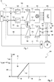
- Figure 1 shows in a schematic representation a block diagram of a drive system 10 for an electric vehicle according to an embodiment of the present invention, which is preferably installed in an electric vehicle.
- the drive system 10 comprises an electric motor 30 for driving wheels, not shown, of the electric vehicle.
- the electric motor 30 comprises a stator, which comprises three phases U, V, W in the form of stator windings, and a rotor which is rotatably mounted in the stator.
- the stator can also have a different number of phases, for example six phases.
- the electrical drive system 10 comprises a transmitter unit 20 for determining an angular position of the rotor relative to the stator, a control unit 100 connected to the transmitter unit 20 and the phases U, V, W for The phases U, V, W of the stator are energized and a heating control unit 90 connected to the regulating unit 100.
- the control unit 100 comprises two comparison modules 110, two current regulators 120 each connected to a comparison module 110, an inverse Park transformation module 130 connected to the two current regulators 120, a modulation module 140 connected to the Park transformation module 130, and power electronics 150 connected to the modulation module 140 , to which the phases U, V, W of the electric motor 30 are connected, three current measurement modules 160 assigned to the phases U, V, W, a Clarke transformation module 170 connected to the current measurement modules 160 and a Park transformation module connected to the Clarke transformation module 170 180.
- the park transformation module 180 is connected to the comparison modules 110, as a result of which a control loop of the control unit 100 is closed.
- Other three-phase embodiments include two current measurement modules 160, since a third current can be calculated from two measured currents on the basis of the knot rule known to those skilled in the art.
- the encoder unit 20 is connected to the inverse Park transformation module 130 and the Park transformation module 180.
- the control unit 100 is configured to provide a plurality of phase currents 151, 152, 153 corresponding to the phases U, V, W of the stator and corresponding to a field-oriented current vector, which comprises a flux-generating current component 112 and a torque-generating current component 111, depending on the determined angular position 21 to energize the phases U, V, W with the provided phase currents 151, 152, 153.
- the heating control unit 90 is connected to the transmitter unit 20 and is configured to provide the control unit 100 with an angular position 21 for the park transformation, which is determined once at a start time 94 of a heating mode of the electric drive system 10.
- the Heating control unit 90 is further configured to predefine control unit 100 a setpoint value 92 for a flux-generating heating current component 112 of a field-oriented heating current vector.
- the control unit 100 is configured to provide a plurality of phase heating currents 151, 152, 153 for the field-oriented heating current vector as a function of the angular position 21 predetermined by the heating control unit 90 and independently of an angular position 21 determined later.
- the encoder unit 20 of the electric vehicle continuously determines the angular position 21 of the rotor of the electric motor 30 relative to the stator of the electric motor 30.
- the control unit 100 provides the field-oriented current vector which the flux-generating current component 112 and the torque-generating current component 111 comprises, depending on the determined angular position 21, three phase currents 151, 152, 153 corresponding to the phases U, V, W of the stator and energizes the phases U, V, W of the stator with the provided phase currents 151, 152, 153.
- the control loop formed by the control unit 100 generates a field-oriented voltage vector with the voltage components 121, 122 by means of the current controller 120 from the current components 111, 112 of the field-oriented current vector.
- the inverse Park transformation module 130 transforms the field-oriented voltage vector into the ⁇ / ⁇ representation, which the modulation module 140 controls.
- the modulation module in turn controls the power electronics 150, which provide the phase currents 151, 152, 153 for the electric motor 30 at its output.
- the three current measuring modules 160 determine a phase-oriented current vector, the components of which are formed by measured phase currents 161, 162, 163.
- the Clarke transformation module 170 transforms the phase-oriented current vector into a current vector of the ⁇ / ⁇ representation with the current components 171, 172.
- the Clarke transformation module 180 transforms the ⁇ / ⁇ current vector into a field-oriented current vector with the current components 181, 182. Based on the current components 181, 182, the comparison modules 110 finally generate the field-oriented current vector described above with the current components 111, 112.
- the heating control unit 90 specifies a field-oriented heating current vector, a starting time 94, a target time 95 and a heating duration, and at the starting time 94 of the heating mode, the transmitter unit 20 determines once an angular position 21 of the rotor, which is controlled by the heating control unit 90 " frozen "and the control unit 100, in particular the Park transformation modules 130, 180 of the control unit 100, is specified.
- the control unit 100 provides a plurality of phase heating currents 151, 152, 153 for the specified field-oriented heating current vector as a function of the frozen angular position 21 and independently of an angular position 21 determined later.
- control unit 100 sets the field-oriented heating current vector as a zero vector at the predetermined starting time 94. Then, starting from the zero vector up to the predetermined target time 95, the control unit 100 increases exclusively the flux-generating heating current component 112 of the field-oriented heating current vector linearly to a setpoint 92 greater than zero of the predetermined field-oriented heating current vector. Any alternative time courses of the flux-generating heating current component 112 are also possible in other embodiments.
- the control unit 100 limits the predetermined setpoint 92 by a maximum value 93 calculated by means of a thermal model of the electric motor 30. From the target point in time 95, the control unit 100 maintains the setpoint 92 for the predetermined heating period.
- control unit 100 also continuously monitors the angular position 21 determined by the transmitter unit 20 from the start time 94 and sets the field-oriented heating current vector as a zero vector if a difference between an angular position 21 determined later and the angular position 21 determined at the start time 94 is a predetermined one Exceeds the threshold value or another error occurs relating to the angular position 21 of the rotor.
- Figure 2 shows in a function graph 200 a time curve of a flow-generating current component 112 of a field-oriented heating current vector for a method according to an embodiment of the present invention.
- the function graph 200 comprises an abscissa 210 on which a time in seconds (s) is plotted, and an ordinate 220 on which a current strength (%) related to the maximum value 93 is plotted.
- the maximum value 93 determined by the control unit 100 and the setpoint 92 predetermined by the heating control unit 90 for the flow-generating current component 112 are constant over time and are accordingly drawn in the function graph 200 as a dashed line parallel to the ordinate 220.
- the start time 94 and the target time 95 are also entered in the function graph 200. Up to and including the start time 94, the flow-generating current component 112 has the value zero. Between the start time 94 and the target time 95, the value of the flux-generating current component 112 increases linearly to the setpoint specified by the heating control unit 90. From the target point in time 95, the flux-generating current component 112 has the predefined setpoint value for the heating duration, which is not shown, as predefined by the heating control unit 90.
Landscapes
- Engineering & Computer Science (AREA)
- Power Engineering (AREA)
- Transportation (AREA)
- Mechanical Engineering (AREA)
- Control Of Ac Motors In General (AREA)
- Electric Propulsion And Braking For Vehicles (AREA)
Description
- Die Erfindung betrifft ein Verfahren zum Betreiben eines Elektromotors eines Elektrofahrzeugs, bei dem eine Gebereinheit eines Elektrofahrzeugs eine Winkelposition eines Rotors eines Elektromotors des Elektrofahrzeugs relativ zu einem Stator des Elektromotors ermittelt und eine Regeleinheit des Elektrofahrzeugs zu einem feldorientierten Stromvektor, welcher eine flusserzeugende Stromkomponente und eine momenterzeugende Stromkomponente umfasst, abhängig von der ermittelten Winkelposition mehrere jeweils zu Phasen des Stators korrespondierende Phasenströme bereitstellt und die mehreren Phasen des Stators mit den bereitgestellten Phasenströmen bestromt. Ferner betrifft die Erfindung ein Antriebssystem für ein Elektrofahrzeug und ein Elektrofahrzeug.
- Elektrofahrzeuge, d. h. Hybridfahrzeuge (Hybrid Electric Vehicles, HEV), Plugin-Hybridfahrzeuge (Plugin Hybrid Electric Vehicles, PHEV) und reine Elektrofahrzeuge (Battery Electric Vehicles, BEV), umfassen definitionsgemäß ein elektrisches Antriebssystem mit einem Elektromotor. Der Elektromotor ist zumeist als permanenterregte oder stromerregte Drehstrommaschine ausgebildet und umfasst einen Stator mit einer Mehrzahl von Statorwicklungen und einen in dem Stator drehbar gelagerten Rotor, welcher typabhängig eine Mehrzahl von Permanentmagneten oder eine Mehrzahl von Rotorwicklungen umfasst.
- Während eines normalen Betriebs des elektrischen Antriebssystems beaufschlagt der Elektromotor den Rotor mit einem Drehmoment, welches Räder des Elektrofahrzeugs drehend antreibt. Das Antriebssystem kann ein Getriebe umfassen, welches konfiguriert ist, eine Drehgeschwindigkeit von angetriebenen Rädern abweichend von einer Drehgeschwindigkeit des Rotors einzustellen. Der normale Betrieb des elektrischen Antriebssystems wird auch Fahrbetriebsart oder Normalbetrieb genannt.
DE 10 2016 213 341 A1 offenbart ein Verfahren, eine Leistung und einen Wirkungsgrad eines Elektrofahrzeugs durch eine Phasenkorrektur zu optimieren. - Infolge von parasitären ohmschen Widerständen der Statorwicklungen und ggf. der Rotorwicklungen entsteht in den stromdurchflossenen Statorwicklungen und ggf. Rotorwicklungen eine elektrische Verlustwärme, welche den Wirkungsgrad des elektrische Antriebssystems und damit eine Reichweite des Elektrofahrzeugs verringert. Die in den Wicklungen erzeugte Verlustwärme ist daher in der Fahrbetriebsart naturgemäß- ebenso wie Durchlass- oder Schaltverluste der Leistungselektronik sowie elektrische Verluste eines Zwischenkreises - unerwünscht. Allerdings können andere Betriebsarten des elektrischen Antriebssystems von der in den Wicklungen erzeugten Verlustwärme profitieren.
- So offenbart die
DE 10 2014 200 337 A1 ein Betriebsverfahren für ein elektrisches Antriebssystem, welches einen Elektromotor mit einer Mehrzahl von Statorwicklungen umfasst. Während des Betriebs des elektrischen Antriebssystems werden durch die Statorwicklungen fließende Phasenströme zumindest teilweise mit Biasströmen beaufschlagt, welche eine Verlustwärme in den Statorwicklungen erhöhen und keinen Beitrag zu einem von dem Elektromotor gestellten Drehmoment leisten. Bei dem Verfahren wird zunächst ein ohmscher Widerstand der Statorwicklungen und dann aus dem ermittelten ohmschen Widerstand eine Temperatur der Statorwicklungen ermittelt. - Die
DE 10 2016 206 765 A1 offenbart ein weiteres elektrisches Antriebssystem für ein Fahrzeug, welches eine Heizbetriebsart aufweist. Das Antriebssystem umfasst einen Elektromotor, welcher einen Stator mit von einem elektrischen Strom durchflossenen Statorwicklungen und einen Rotor mit von einem elektrischen Strom durchflossenen Rotorwicklungen umfasst, und ein mit dem Elektromotor drehfest verbundenes Getriebe umfasst. Ferner weist das elektrische Antriebssystem einen sich durch den Rotor und das Getriebe erstreckenden Schmiermittelkreislauf auf. In einer Heizbetriebsart wird das elektrische Antriebssystem bei einem unveränderten Antriebsmoment mit einem verringerten Strom in den Statorwicklungen und einem erhöhtem Strom in den Rotorwicklungen betrieben. Infolge des erhöhten Rotorstroms entsteht in dem Rotor eine zusätzliche Verlustwärme, welche ein Schmiermittel in dem Schmiermittelkreislauf erwärmt. Auf diese Weise werden eine Lebensdauer des Getriebes und ein Wirkungsgrad des elektrischen Antriebssystems erhöht. - Übliche elektrische Antriebssysteme für Fahrzeuge umfassen neben dem Elektromotor einen Regelkreis, welcher gewöhnlich mit vektoriellen Darstellungen von elektrischen Größen, d. h. anliegenden elektrischen Spannungen oder fließenden elektrischen Strömen, beschrieben wird.
- Eine erste vektorielle Darstellung wird aus entlang einer Umfangsrichtung des Elektromotors gleichverteilten Statorwicklungen gewonnen, indem den Statorwicklungen zugeordnete gleichartige elektrische Größen mittels der bekannten sogenannten Clarke-Transformation oder α/β-Transformation in ein statorfestes Bezugssystem in Form einer komplexe Zahlenebene abgebildet werden. Dabei werden üblicherweise der Ursprung der komplexen Zahlenebene in eine Drehachse des Rotors und eine positive reelle α-Achse des Bezugssystems kollinear zu einer bestimmten Statorwicklung des Elektromotors gewählt. Mittels der Clarke-Transformation wird eine Mehrzahl gleichartiger elektrischer Größen jeweils in eine komplexe Zahl α + j · β, mithin eine zweidimensionale vektorielle Darstellung (α,β) überführt, wobei der Realteil einer elektrischen Größe mit α und der Imaginärteil der elektrischen Größe mit β indiziert werden.
- Eine zweite vektorielle Darstellung, die sogenannte feldorientierte Darstellung, wird aus der ersten vektoriellen Darstellung mittels der bekannten sogenannten Park-Transformation oder d/q-Transformation gewonnen. Die Park-Transformation bildet statorfeste elektrische Größen (α, β) mittels einer Winkelposition φ des Rotors relativ zu dem Stator in eine zweidimensionale vektorielle Darstellung (d,q) in ein rotorfestes Bezugssystem ab. Dabei stehen d für eine rein flusserzeugende elektrische Größe und für eine rein momenterzeugende elektrische Größe.
FR 2 990 088 A1 - Bei einem elektrischen Antriebssystem mit einem feldorientierten Regelkreis sind die elektrischen Größen für die Statorwicklungen des Elektromotors durch flusserzeugende Vektorkomponenten, welche - abgesehen von Reluktanzmomenten - keinen Beitrag zur Momenterzeugung leisten, und momenterzeugende Vektorkomponenten, welche keinen Beitrag zur Flusserzeugung leisten, definiert.
- Die
DE 10 2016 212 852 A1 offenbart ein elektrisches Antriebssystem für ein Fahrzeug. Das Antriebssystem umfasst einen als Synchronmaschine ausgebildeten Elektromotor und eine feldorientierte Regeleinheit. In einer Heizbetriebsart des Antriebssystems wird der Elektromotor mittels einer Überlagerung eines schnell oszillierenden momenterzeugenden Stroms und eines zeitlich konstanten flusserzeugenden Stroms betrieben. Der momenterzeugende Strom lässt den Rotor mit relativ hoher Frequenz um eine Ruhelage pendeln, so dass ein aus der Pendelbewegung resultierendes Drehmoment insbesondere für einen Fahrer des Fahrzeugs unmerklich und im Mittel Null ist. Durch den flusserzeugenden Strom wird eine zusätzliche Verlustwärme zum Beheizen einer Fahrgastzelle des Fahrzeugs erzeugt.EP 3 081 429 A1 offenbart eine Ladebetriebsart eine Elektrofahrzeugs, welche ein Vibrieren des Motors während der Ladebetriebsart ebenfalls mittels eines schnell oszillierenden momenterzeugenden Stroms reduziert. - Allerdings können bei einem elektrischen Antriebssystem mit einer feldorientierten Regeleinheit von dem Elektromotor unerwünschte Drehmomente gestellt werden, wenn die für die Park-Transformation verwendete Winkelposition φ des Rotors nicht mit der tatsächlichen Winkelposition des Rotors übereinstimmt. Denn resultiert eine feldorientierte eigentlich rein flusserzeugende elektrische Größe mittels einer auf der unzutreffenden Winkelposition φ des Rotors beruhenden inversen Park-Transformation in einer momenterzeugenden Bestromung des Elektromotors.
- Die Winkelposition φ wird gewöhnlich von einer Gebereinheit ermittelt und für die Regeleinheit bereitgestellt. Wenn die Gebereinheit ausfällt oder eine Fehlfunktion aufweist, stellt der Elektromotor ein unbeabsichtigtes Drehmoment, welches das Elektrofahrzeug beschleunigt.
- Ein Beschleunigen des Elektrofahrzeugs geht mit einer erhöhten Unfallgefahr insbesondere dann einher, wenn das elektrische Antriebssystem während eines Stillstands des Elektrofahrzeugs vor einer Ankunft eines Fahrers des Elektrofahrzeugs unbeaufsichtigt in einer Heizbetriebsart als Standheizung für eine Fahrgastzelle des Elektrofahrzeugs betrieben wird.
- Der Erfindung liegt daher die Aufgabe zugrunde, ein verbessertes Verfahren zum Betreiben eines Elektromotors eines Elektrofahrzeugs vorzuschlagen, welches eine im Stillstand des Elektrofahrzeugs sichere Heizbetriebsart aufweist. Darüber hinaus ist es Aufgabe der Erfindung, ein Antriebssystem für ein Elektrofahrzeug sowie ein Elektrofahrzeug zur Verfügung zu stellen.
- Ein Gegenstand der Erfindung ist ein Verfahren zum Betreiben eines Elektromotors eines Elektrofahrzeugs, bei dem eine Gebereinheit eines Elektrofahrzeugs eine Winkelposition eines Rotors eines Elektromotors des Elektrofahrzeugs relativ zu einem Stator des Elektromotors ermittelt und eine Regeleinheit des Elektrofahrzeugs zu einem feldorientierten Stromvektor, welcher eine flusserzeugende Stromkomponente und eine momenterzeugende Stromkomponente umfasst, abhängig von der ermittelten Winkelposition mehrere jeweils zu Phasen des Stators korrespondierende Phasenströme bereitstellt und die mehreren Phasen des Stators mit den bereitgestellten Phasenströmen bestromt. Der Elektromotor, die Regeleinheit und die Gebereinheit sind Komponenten eines elektrischen Antriebssystems des Elektrofahrzeugs.
- Mit dem Verfahren wird ein als eine permanenterregte oder stromerregte Drehstrommaschine ausgebildeter Elektromotor mit einer Mehrzahl von jeweils eine Phase des Elektromotors definierenden und ein oder mehrere Polpaare erzeugenden Statorwicklungen betrieben. Dabei sind die Pole eines einzigen erzeugten Polpaares in dem Stator jeweils jederzeit gegenüberliegend, d. h. in einem relativen Winkel von 180°, und die Pole mehrerer erzeugter Polpaare in der Umfangsrichtung des Stators in einer festen Reihenfolge alternierend angeordnet. Beispielsweise wechseln sich Nord- und Südpole zweier erzeugter Polpaare jeweils in relativen Winkeln von 90° derart ab, dass jederzeit jeweils die Nordpole gegenüberliegend und die Südpole gegenüberliegend angeordnet sind.
- Die Regeleinheit berechnet zu einer feldorientierten vektoriellen Darstellung elektrischer Größen mittels einer Park-Transformation und einer Clarke-Transformation oder deren Inverser phasenorientierte elektrische Größen, erzeugt die berechneten elektrischen Größen und beaufschlagt den Elektromotor, genauer gesagt die Statorwicklungen des Elektromotors, mit den erzeugten elektrischen Größen.
- Bei dem erfindungsgemäßen Verfahren stellt die Regeleinheit zu einem feldorientierten Heizstromvektor abhängig von einer zu einem Startzeitpunkt einmalig ermittelten Winkelposition und unabhängig von einer später ermittelten Winkelposition mehrere Phasenheizströme bereit. Ein Heizstromvektor umfasst eine flusserzeugende Stromkomponente, welche keinen Beitrag zum Erzeugen eines Antriebsmoments leistet, sondern allein einem Erzeugen von Verlustwärme in den Statorwicklungen des Elektromotors dient. Anders gesagt wird die zu Beginn, d. h. bei einem Start einer Heizbetriebsart des elektrischen Antriebssystems, einmalig ermittelte Winkelposition "eingefroren".
- Wenn die ermittelte Winkelposition infolge eines Ausfalls oder einer Fehlfunktion der Gebereinheit nicht mit der tatsächlichen Winkelposition des Rotors übereinstimmt, weicht sie von der tatsächlichen Winkelposition des Rotors höchstens um 180° geteilt durch die Anzahl der Polpaare ab, beispielsweise 60° im häufigen Fall dreier Polpaare oder 36° im Fall von fünf Polpaaren. Entsprechend verschwindet ein unbeabsichtigt gestelltes Drehmoment spätestens nach einer entsprechenden Drehung des Rotors um diesen Winkel, d. h. um 60° im Fall dreier Polpaare, d. h. das Elektrofahrzeug kommt nach maximal einer solchen Rotordrehung zum Stillstand. Eine solche Rotordrehung entspricht unter Berücksichtigung einer üblichen Untersetzung des Getriebes und eines üblichen Durchmessers von angetriebenen Rädern des Elektrofahrzeugs einer Fahrtstrecke von wenigen Zentimetern. In der nach Zurücklegen der sehr kurzen Fahrtstrecke erreichten neuen Position ist das Elektrofahrzeug dank der eingefrorenen Winkelposition drehmomentfrei und folglich stabilisiert.
- In einer erfindungsgemäßen Ausführungsform stellt die Regeleinheit zu dem Startzeitpunkt den feldorientierten Heizstromvektor als einen Nullvektor. Der feldorientierte Nullvektor umfasst sowohl eine verschwindende flusserzeugende Heizstromkomponente als auch eine verschwindende momenterzeugende Komponente, d. h. der Elektromotor wird beim Start der Heizbetriebsart nicht mit einem elektrischen Strom beaufschlagt.
- Weiterhin erfindungsgemäß erhöht die Regeleinheit ausgehend von dem Nullvektor bis zu einem Zielzeitpunkt ausschließlich die flusserzeugende Heizstromkomponente des feldorientierten Heizstromvektors auf einen von einer Heizsteuereinrichtung vorgegebenen Sollwert größer Null. Auf diese Weise wird die Heizwirkung des elektrischen Antriebssystems zwischen dem Startzeitpunkt und dem Zielzeitpunkt ohne Momentwirkung allmählich hochgefahren. Die kürzest mögliche Zeitspanne zwischen dem Startzeitpunkt und dem Endzeitpunkt ist bekanntlich durch die Induktivitäten der Statorwicklungen bestimmt.
- Vorteilhaft erhöht die Regeleinheit die flusserzeugende Heizstromkomponente zwischen dem Startzeitpunkt und dem Zielzeitpunkt linear. Eine lineare Rampe ist schaltungstechnisch einfach zu implementieren. Jedoch kann auch ein beliebiger anderer Verlauf gewählt werden, um den Sollwert zu erreichen.
- In weiteren Ausführungsformen behält die Regeleinheit den Sollwert ab dem Zielzeitpunkt für eine von der Heizsteuereinheit vorgegebene Heizdauer bei. Dadurch wird sichergestellt, dass die Heizbetriebsart des elektrischen Antriebssystems eine in einer Traktionsbatterie des Elektrofahrzeugs gespeicherte elektrische Energie nicht vollständig verbraucht.
- In anderen Ausführungsformen begrenzt die Regeleinheit den von der Heizsteuereinheit vorgegebenen Sollwert durch einen mittels eines thermischen Modells des Elektromotors berechneten Maximalwert. Der Maximalwert stellt sicher, dass sich der Elektromotor in der Heizbetriebsart des elektrischen Antriebssystems nicht überhitzt, wodurch ein Schadenrisiko des Elektromotors infolge der Heizbetriebsart gering ist.
- In einer weiteren bevorzugten Ausführungsform überwacht die Regeleinheit die von der Gebereinheit ermittelte Winkelposition ab dem Startzeitpunkt fortlaufend und stellt den feldorientierten Heizstromvektor als einen Nullvektor und/oder wechselt in einen vorbestimmten Fehlerzustand, wenn eine Differenz zwischen einer später ermittelten Winkelposition von der zu dem Startzeitpunkt ermittelten Winkelposition einen vorbestimmten Schwellwert übersteigt. Dies bewirkt bei außergewöhnlichen Fehlfunktionen der Gebereinheit eine Notabschaltung der Heizbetriebsart des elektrischen Antriebssystems.
- Gegenstand der Erfindung ist auch ein Antriebssystem für ein Elektrofahrzeug, mit einem Elektromotor, welcher einen mehrere Phasen umfassenden Stator und einen Rotor umfasst, einer Gebereinheit zum Ermitteln einer Winkelposition des Rotors relativ zu dem Stator und einer mit der Gebereinheit und den mehreren Phasen verbundenen Regeleinheit zum Bestromen der mehreren Phasen des Stators, bei dem die Regeleinheit konfiguriert ist, zu einem feldorientierten Stromvektor, welcher eine flusserzeugende Stromkomponente und eine momenterzeugende Stromkomponente umfasst, abhängig von der ermittelten Winkelposition mehrere jeweils zu Phasen des Stators korrespondierende Phasenströme bereitzustellen und die mehreren Phasen mit den bereitgestellten Phasenströmen zu bestromen. Das elektrische Antriebssystem umfasst demnach einen Elektromotor, eine einen feldorientierten Regelkreis bildende Regeleinheit und eine Gebereinheit. Ein solches Antriebssystem ist in einer Vielzahl von Elektrofahrzeugen verbaut. Entsprechend ergeben sich für das erfindungsgemäße elektrische Antriebssystem zahlreiche Verwendungsmöglichkeiten.
- Bei dem erfindungsgemäßen Antriebssystem ist die Regeleinheit konfiguriert, zu einem feldorientierten Heizstromvektor abhängig von einer zu einem Startzeitpunkt einmalig ermittelten Winkelposition und unabhängig von einer später ermittelten Winkelposition mehrere Phasenheizströme bereitzustellen. Das elektrische Antriebssystem weist eine Heizbetriebsart auf, welche ein Beheizen einer Fahrgastzelle des Elektrofahrzeugs sowie weiterer Komponenten des Elektrofahrzeugs, beispielsweise der Traktionsbatterie, erlaubt. Bevorzugt ist das Antriebssystem konfiguriert, ein erfindungsgemäßes Verfahren auszuführen.
- In einer weiteren Ausführungsform umfasst das Antriebssystem eine mit der Regeleinheit verbundene Heizsteuereinheit, welche konfiguriert ist, der Regeleinheit einen Sollwert für eine flusserzeugende Heizstromkomponente des Heizstromvektors zu stellen. Die Heizsteuereinheit bestimmt ferner den Startzeitpunkt und einen Zielzeitpunkt sowie eine Heizdauer der Heizbetriebsart.
- In vorteilhaften Ausführungsformen umfasst der Stator des Elektromotors drei oder mindestens drei Phasen. Dreiphasige Drehstrommaschinen sind als Elektromotoren von Elektrofahrzeugen weit verbreitet. Die Phasen werden gewöhnlich mit U, V, W bezeichnet. In alternativen Ausführungsformen umfasst der Stator des Elektromotors eine von drei abweichende Anzahl von Phasenwicklungen, z.B. sechs Phasenwicklungen.
- Ein weiterer Gegenstand der Erfindung ist ein Elektrofahrzeug mit einem erfindungsgemäßen Antriebssystem. Das Elektrofahrzeug weist eine sichere Standheizung auf, welche auf dem elektrischen Antriebssystem beruht und keine darüber hinausgehenden Komponenten erfordert.
- Ein wesentlicher Vorteil des erfindungsgemäßen Verfahrens zum Betreiben eines Elektromotors eines Elektrofahrzeugs besteht darin, dass die Heizbetriebsart des elektrischen Antriebssystems tolerant gegenüber einem Ausfall oder eine Fehlfunktion der Gebereinheit ausgestaltet ist. Infolgedessen ist eine Unfallgefahr des Elektrofahrzeugs aufgrund der Heizbetriebsart höchstens vernachlässigbar erhöht. Zudem erfordert das Betriebsverfahren zum Ausführen der Heizbetriebsart keine zusätzlichen Komponenten.
- Die Erfindung ist anhand einer Ausführungsform in den Zeichnungen schematisch dargestellt und wird unter Bezugnahme auf die Zeichnungen weiter beschrieben. Es zeigt:
- Figur 1
- in einer schematischen Darstellung ein Blockdiagramm eines Antriebssystems für ein Elektrofahrzeug nach einer Ausführungsform der vorliegenden Erfindung;
- Figur 2
- in einem Funktionsgraph einen Zeitverlauf einer flussgebenden Stromkomponente eines feldorientierten Heizstromvektors für ein Verfahren nach einer Ausführungsform der vorliegenden Erfindung.
-
Figur 1 zeigt in einer schematischen Darstellung ein Blockdiagramm eines Antriebssystems 10 für ein Elektrofahrzeug nach einer Ausführungsform der vorliegenden Erfindung, welches bevorzugt in einem Elektrofahrzeug verbaut ist. - Das Antriebssystem 10 umfasst einen Elektromotor 30 zum Antreiben nicht dargestellter Räder des Elektrofahrzeugs. Der Elektromotor 30 umfasst einen Stator, welcher drei Phasen U, V, W in Form von Statorwicklungen umfasst, und einen in dem Stator drehbar gelagerten Rotor. Alternativ kann der Stator auch eine abweichende Anzahl von Phasen, beispielsweise sechs Phasen, umfassen.
- Ferner umfasst das elektrische Antriebssystem 10 eine Gebereinheit 20 zum Ermitteln einer Winkelposition des Rotors relativ zu dem Stator, eine mit der Gebereinheit 20 und den Phasen U, V, W verbundene Regeleinheit 100 zum Bestromen der Phasen U, V, W des Stators und eine mit der Regeleinheit 100 verbundene Heizsteuereinheit 90.
- Die Regeleinheit 100 umfasst zwei Vergleichsmodule 110, zwei jeweils mit einem Vergleichsmodul 110 verbundene Stromregler 120, ein mit den beiden Stromreglern 120 verbundenes inverses Park-Transformationsmodul 130, ein mit dem Park-Transformationsmodul 130 verbundenes Modulationsmodul 140, eine mit dem Modulationsmodul 140 verbundene Leistungselektronik 150, an welche die Phasen U, V, W des Elektromotors 30 angeschlossen sind, drei den Phasen U, V, W zugeordnete Strommessmodule 160, ein mit den Strommessmodulen 160 verbundenes Clarke-Transformationsmodul 170 und ein mit dem Clarke-Transformationsmodul 170 verbundenes Park-Transformationsmodul 180. Das Park-Transformationsmodul 180 ist mit den Vergleichsmodulen 110 verbunden, wodurch ein Regelkreis der Regeleinheit 100 geschlossen ist. Andere dreihphasige Ausführungsformen umfassen zwei Strommessmodule 160, da sich ein dritter Strom aufgrund der dem Fachmann bekannten Knotenregel aus zwei gemessenen Strömen berechnen lässt.
- Die Gebereinheit 20 ist mit dem inversen Park-Transformationsmodul 130 und dem Park-Transformationsmodul 180 verbunden.
- Die Regeleinheit 100 ist konfiguriert, zu einem feldorientierten Stromvektor, welcher eine flusserzeugende Stromkomponente 112 und eine momenterzeugende Stromkomponente 111 umfasst, abhängig von der ermittelten Winkelposition 21 mehrere jeweils zu den Phasen U, V, W des Stators korrespondierende Phasenströme 151, 152, 153 bereitzustellen und die Phasen U, V, W mit den bereitgestellten Phasenströmen 151, 152, 153 zu bestromen.
- Die Heizsteuereinheit 90 ist mit der Gebereinheit 20 verbunden und konfiguriert, der Regeleinheit 100 eine zu einem Startzeitpunkt 94 einer Heizbetriebsart des elektrischen Antriebssystems 10 einmalig ermittelte Winkelposition 21 für die Park-Transformation vorzugeben. Die Heizsteuereinheit 90 ist ferner konfiguriert, der Regeleinheit 100 einen Sollwert 92 für eine flusserzeugende Heizstromkomponente 112 eines feldorientierten Heizstromvektors vorzugeben. Entsprechend ist die Regeleinheit 100 konfiguriert, zu dem feldorientierten Heizstromvektor abhängig von der von der Heizsteuereinheit 90 vorgegebenen Winkelposition 21 und unabhängig von einer später ermittelten Winkelposition 21 mehrere Phasenheizströme 151, 152, 153 bereitzustellen.
- Während jedes Betriebs des elektrischen Antriebssystems 10, insbesondere in der Fahrbetriebsart, ermittelt die Gebereinheit 20 des Elektrofahrzeugs fortlaufend die Winkelposition 21 des Rotors des Elektromotors 30 relativ zu dem Stator des Elektromotors 30. Die Regeleinheit 100 stellt zu dem feldorientierten Stromvektor, welcher die flusserzeugende Stromkomponente 112 und die momenterzeugende Stromkomponente 111 umfasst, abhängig von der ermittelten Winkelposition 21 drei jeweils zu den Phasen U, V, W des Stators korrespondierende Phasenströme 151, 152, 153 bereit und bestromt die Phasen U, V, W des Stators mit den bereitgestellten Phasenströmen 151, 152, 153.
- Der von der Regeleinheit 100 gebildete Regelkreis erzeugt mittels der Stromregler 120 aus den Stromkomponenten 111, 112 des feldorientierten Stromvektors einen feldorientierten Spannungsvektor mit den Spannungskomponenten 121, 122. Das inverse Park-Transformationsmodul 130 transformiert den feldorientierten Spannungsvektor in die α/β-Darstellung, welche das Modulationsmodul 140 ansteuert. Das Modulationsmodul steuert seinerseits die Leistungselektronik 150, welche an ihrem Ausgang die Phasenströme 151, 152, 153 für den Elektromotor 30 bereitstellt.
- Die drei Strommessmodule 160 ermitteln einen phasenorientierten Stromvektor, dessen Komponenten von gemessenen Phasenströmen 161, 162, 163 gebildet werden. Das Clarke-Transformationsmodul 170 transformiert den phasenorientierten Stromvektor in einen Stromvektor derα/β-Darstellung mit den Stromkomponenten 171, 172. Das Clarke-Transformationsmodul 180 transformiert den α/β-Stromvektor in einen feldorientierten Stromvektor mit den Stromkomponenten 181, 182. Die Vergleichsmodule 110 erzeugen ausgehend von den Stromkomponenten 181, 182 schließlich den eingangs beschriebenen feldorientierten Stromvektor mit den Strom komponenten 111, 112.
- In einer Heizbetriebsart des elektrischen Antriebssystems 10 gibt die Heizsteuereinheit 90 einen feldorientierten Heizstromvektor, einen Startzeitpunkt 94, einen Zielzeitpunkt 95 und eine Heizdauer vor und ermittelt die Gebereinheit 20 zu dem Startzeitpunkt 94 der Heizbetriebsart einmalig eine Winkelposition 21 des Rotors, welche von der Heizsteuereinheit 90 "eingefroren" und der Regeleinheit 100, insbesondere den Park-Transformationsmodulen 130, 180 der Regeleinheit 100, vorgegeben wird.
- Die Regeleinheit 100 stellt zu dem vorgegebenen feldorientierten Heizstromvektor abhängig von der eingefrorenen Winkelposition 21 und unabhängig von einer später ermittelten Winkelposition 21 mehrere Phasenheizströme 151, 152, 153 bereit.
- Im Einzelnen stellt die Regeleinheit 100 zu dem vorgegebenen Startzeitpunkt 94 den feldorientierten Heizstromvektor als einen Nullvektor. Dann erhöht die Regeleinheit 100 ausgehend von dem Nullvektor bis zu dem vorgegebenen Zielzeitpunkt 95 ausschließlich die flusserzeugende Heizstromkomponente 112 des feldorientierten Heizstromvektors linear auf einen Sollwert 92 größer Null des vorgegebenen feldorientierten Heizstromvektors. Beliebige alternative Zeitverläufe der flusserzeugenden Heizstromkomponente 112 sind in anderen Ausführungsformen ebenfalls möglich.
- Die Regeleinheit 100 begrenzt den vorgegebenen Sollwert 92 durch einen mittels eines thermischen Modells des Elektromotors 30 berechneten Maximalwert 93. Ab dem Zielzeitpunkt 95 behält die Regeleinheit 100 den Sollwert 92 für die vorgegebene Heizdauer bei.
- In der Heizbetriebsart überwacht die Regeleinheit 100 ferner die von der Gebereinheit 20 ermittelte Winkelposition 21 ab dem Startzeitpunkt 94 fortlaufend und stellt den feldorientierten Heizstromvektor als einen Nullvektor, wenn eine Differenz zwischen einer später ermittelten Winkelposition 21 und der zu dem Startzeitpunkt 94 ermittelten Winkelposition 21 einen vorbestimmten Schwellwert übersteigt oder ein anderer Fehler betreffend die Winkelposition 21 des Rotors auftritt.
-
Figur 2 zeigt in einem Funktionsgraph 200 einen Zeitverlauf einer flusserzeugenden Stromkomponente 112 eines feldorientierten Heizstromvektors für ein Verfahren nach einer Ausführungsform der vorliegenden Erfindung. Der Funktionsgraph 200 umfasst eine Abszisse 210, an welcher eine Zeit in Sekunden (s) abgetragen ist, und eine Ordinate 220, an welcher eine auf den Maximalwert 93 bezogene Stromstärke (%) abgetragen ist. - Der von der Regeleinheit 100 bestimmte Maximalwert 93 und der von der Heizsteuereinheit 90 vorgegebene Sollwert 92 für die flusserzeugende Stromkomponente 112 sind zeitlich konstant und entsprechend als gestrichelte Linie parallel zu der Ordinate 220 in den Funktionsgraph 200 eingezeichnet.
- Ferner sind in den Funktionsgraph 200 der Startzeitpunkt 94 und der Zielzeitpunkt 95 eingetragen. Bis einschließlich zum Startzeitpunkt 94 hat die flusserzeugende Stromkomponente 112 den Wert Null. Zwischen dem Startzeitpunkt 94 und dem Zielzeitpunkt 95 erhöht sich der Wert der flusserzeugenden Stromkomponente 112 linear auf den von der Heizsteuereinheit 90 vorgegebenen Sollwert. Ab dem Zielzeitpunkt 95 hat die flusserzeugende Stromkomponente 112 für die von der Heizsteuereinheit 90 vorgegebene nicht eingezeichnete Heizdauer den vorgegebenen Sollwert.
-
- 10
- System
- 20
- Gebereinheit
- 21
- Winkelposition φ
- 30
- Elektromotor
- U, V, W
- Phasen
- 90
- Heizsteuereinheit
- 91
- Sollwert Iq,Soll für momenterzeugende Stromkomponente
- 92
- Sollwert Id,Soll für flusserzeugende Stromkomponente
- 93
- Maximalwert
- 94
- Startzeitpunkt
- 95
- Zielzeitpunkt
- 100
- Regeleinheit
- 110
- Vergleichsmodul
- 111
- momenterzeugende Stromkomponente
- 112
- flusserzeugende Stromkomponente
- 120
- Stromregler
- 121
- feldorientierte Spannungskomponente uq
- 122
- feldorientierte Spannungskomponente ud
- 130
- Inverses Park-Transformationsmodul
- 131
- reelle Spannungskomponente uα
- 132
- imaginäre Spannungskomponente uβ
- 140
- Modulationsmodul
- 150
- Leistungselektronik
- 151
- phasenorientierte Stromkomponente iU
- 152
- phasenorientierte Stromkomponente iV
- 153
- phasenorientierte Stromkomponente iW
- 160
- Strommessmodul
- 161
- gemessene phasenorientierte Stromkomponente iU
- 162
- gemessene phasenorientierte Stromkomponente iV
- 163
- gemessene phasenorientierte Stromkomponente iW
- 170
- Clarke-Transformationsmodul
- 171
- reelle Stromkomponente iα
- 172
- imaginäre Stromkomponente iβ
- 180
- Park-Transformationsmodul
- 181
- Istwert Iq,Ist für momenterzeugende Stromkomponente
- 182
- Istwert Id,Ist für flusserzeugende Stromkomponente
- 200
- Funktionsgraph
- 210
- Abszisse
- 220
- Ordinate
Claims (8)
- Verfahren zum Betreiben eines Elektromotors (30) eines Elektrofahrzeugs, bei dem eine Gebereinheit (20) eines Antriebssystems eines Elektrofahrzeugs eine Winkelposition (21) eines Rotors eines Elektromotors (30) des Antriebssystems relativ zu einem Stator des Elektromotors (30) ermittelt und eine Regeleinheit (100) des Antriebssystems in einer Fahrbetriebsart zu einem feldorientierten Stromvektor, welcher eine flusserzeugende Stromkomponente (112) und eine momenterzeugende Stromkomponente (111) umfasst, abhängig von der ermittelten Winkelposition (21) mehrere jeweils zu Phasen (U, V, W) des Stators korrespondierende Phasenströme (151, 152, 153) bereitstellt und die mehreren Phasen (U, V, W) des Stators mit den bereitgestellten Phasenströmen (151, 152, 153) bestromt, dadurch gekennzeichnet, dass die Regeleinheit (100) in einer Heizbetriebsart des Antriebssystems zu einem feldorientierten Heizstromvektor abhängig von einer zu einem Startzeitpunkt (93) der Heizbetriebsart einmalig ermittelten Winkelposition (21) und unabhängig von einer später ermittelten Winkelposition (21) mehrere Phasenheizströme (151, 152, 153) bereitstellt, wobei die Regeleinheit (100) zu dem Startzeitpunkt (94) den feldorientierten Heizstromvektor als einen Nullvektor stellt und ausgehend von dem Nullvektor bis zu einem Zielzeitpunkt (95) ausschließlich eine flusserzeugende Heizstromkomponente (112) des feldorientierten Heizstromvektors auf einen von einer Heizsteuereinrichtung (90) des Antriebssystems vorgegebenen Sollwert (92) größer Null erhöht.
- Verfahren nach Anspruch 1, bei dem die Regeleinheit (100) die flusserzeugende Heizstromkomponente (112) zwischen dem Startzeitpunkt (94) und dem Zielzeitpunkt (95) linear erhöht.
- Verfahren nach einem der Ansprüche 1 oder 2, bei dem die Regeleinheit (100) den Sollwert (92) ab dem Zielzeitpunkt (95) für eine von der Heizsteuereinheit (90) vorgegebene Heizdauer beibehält.
- Verfahren nach einem der Ansprüche 1 bis 3, bei dem die Regeleinheit (100) die von der Gebereinheit (20) ermittelte Winkelposition (21) ab dem Startzeitpunkt (94) fortlaufend überwacht und den feldorientierten Heizstromvektor als einen Nullvektor stellt und/oder in einen vorbestimmten Fehlerzustand wechselt, wenn eine Differenz zwischen einer später ermittelten Winkelposition (21) von der zu dem Startzeitpunkt (94) ermittelten Winkelposition (21) einen vorbestimmten Schwellwert übersteigt.
- Antriebssystem (10) für ein Elektrofahrzeug, mit einem Elektromotor (30), welcher einen mehrere Phasen (U, V, W) umfassenden Stator und einen Rotor umfasst, einer Gebereinheit (20) zum Ermitteln einer Winkelposition des Rotors relativ zu dem Stator und einer mit der Gebereinheit (20) und den mehreren Phasen (U, V, W) verbundenen Regeleinheit (100) zum Bestromen der mehreren Phasen (U, V, W) des Stators, bei dem die Regeleinheit (100) konfiguriert ist, in einer Fahrbetriebsart zu einem feldorientierten Stromvektor, welcher eine flusserzeugende Stromkomponente (112) und eine momenterzeugende Stromkomponente (111) umfasst, abhängig von der ermittelten Winkelposition (21) mehrere jeweils zu Phasen (U, V, W) des Stators korrespondierende Phasenströme (151, 152, 153) bereitzustellen und die mehreren Phasen (U, V, W) mit den bereitgestellten Phasenströmen (151, 152, 153) zu bestromen, dadurch gekennzeichnet, dass die Regeleinheit (100) konfiguriert ist, in einer Heizbetriebsart des Antriebssystems zu einem feldorientierten Heizstromvektor abhängig von einer zu einem Startzeitpunkt (93) der Heizbetriebsart einmalig ermittelten Winkelposition (21) und unabhängig von einer später ermittelten Winkelposition (21) mehrere Phasenheizströme (151, 152, 153) bereitzustellen und dabei zu dem Startzeitpunkt (94) den feldorientierten Heizstromvektor als einen Nullvektor zu stellen und ausgehend von dem Nullvektor bis zu einem Zielzeitpunkt (95) ausschließlich eine flusserzeugende Heizstromkomponente (112) des feldorientierten Heizstromvektors auf einen von einer Heizsteuereinrichtung (90) des Antriebssystems vorgegebenen Sollwert (92) größer Null zu erhöhen.
- Antriebssystem nach Anspruch 5, mit einer mit der Regeleinheit (100) verbundenen Heizsteuereinheit (90), welche konfiguriert ist, für die Regeleinheit (100) einen Sollwert (92) für eine flusserzeugende Heizstromkomponente (112) des Heizstromvektors zu stellen.
- Antriebssystem nach Anspruch 6, bei dem der Stator des Elektromotors (30) drei oder mindestens drei Phasen (U, V, W) umfasst.
- Elektrofahrzeug mit einem Antriebssystem (10) nach einem der Ansprüche 5 bis 7.
Applications Claiming Priority (1)
| Application Number | Priority Date | Filing Date | Title |
|---|---|---|---|
| DE102019200863.1A DE102019200863A1 (de) | 2019-01-24 | 2019-01-24 | Heizbetrieb eines elektrischen Antriebssystems eines Fahrzeugs |
Publications (2)
| Publication Number | Publication Date |
|---|---|
| EP3686046A1 EP3686046A1 (de) | 2020-07-29 |
| EP3686046B1 true EP3686046B1 (de) | 2021-10-13 |
Family
ID=68886764
Family Applications (1)
| Application Number | Title | Priority Date | Filing Date |
|---|---|---|---|
| EP19215151.2A Active EP3686046B1 (de) | 2019-01-24 | 2019-12-11 | Heizbetrieb eines elektrischen antriebssystems eines fahrzeugs |
Country Status (2)
| Country | Link |
|---|---|
| EP (1) | EP3686046B1 (de) |
| DE (1) | DE102019200863A1 (de) |
Families Citing this family (3)
| Publication number | Priority date | Publication date | Assignee | Title |
|---|---|---|---|---|
| CN115833707A (zh) * | 2022-11-25 | 2023-03-21 | 广汽埃安新能源汽车股份有限公司 | 一种车辆电机产热的控制方法及系统 |
| DE102023202083A1 (de) * | 2023-03-08 | 2024-09-12 | Magna Pt B.V. & Co. Kg | Verfahren für ein Hybrid- oder Elektrofahrzeug mit Wärmepumpenanordnung zur Vorkonditionierung |
| EP4472063A1 (de) | 2023-06-02 | 2024-12-04 | Siemens Aktiengesellschaft | Umrichterbasierte heizfunktion einer dynamoelektrischen maschine |
Family Cites Families (8)
| Publication number | Priority date | Publication date | Assignee | Title |
|---|---|---|---|---|
| FR2990088B1 (fr) * | 2012-04-30 | 2014-05-09 | Renault Sa | Procede de determination du decalage angulaire entre le rotor et le stator d'une machine electrique d'un vehicule automobile |
| DE102012224071A1 (de) * | 2012-12-20 | 2014-06-26 | Siemens Aktiengesellschaft | Heizung für Elektrofahrzeuge und Verfahren zu deren Ansteuerung |
| DE102014200337A1 (de) | 2014-01-10 | 2015-07-16 | Robert Bosch Gmbh | Bestromen und Messen der Temperatur von Statorwicklungen einer zumindest motorisch betreibbaren elektrischen Drehfeldmaschine |
| DE102014217959A1 (de) * | 2014-09-09 | 2016-03-10 | Bayerische Motoren Werke Aktiengesellschaft | Verfahren und Klimatisierungseinrichtung zum Klimatisieren eines Innenraums eines elektrisch angetriebenen Fahrzeugs |
| GB2537351B (en) * | 2015-04-07 | 2017-05-24 | Nissan Motor Mfg (Uk) Ltd | Control method for integrated electric drive and charger apparatus for a grid enabled vehicle |
| DE102016206765B4 (de) | 2016-04-21 | 2023-02-02 | Bayerische Motoren Werke Aktiengesellschaft | Vorrichtung und Verfahren zum Ansteuern einer in einem Fahrzeug angeordneten Synchronmaschine |
| DE102016212852A1 (de) | 2016-07-14 | 2018-01-18 | Bayerische Motoren Werke Aktiengesellschaft | Ansteuervorrichtung für eine und Verfahren zum Ansteuern einer in einem Fahrzeug angeordneten Synchronmaschine |
| DE102016213341A1 (de) * | 2016-07-21 | 2018-01-25 | Continental Automotive Gmbh | Phasenkorrektur bei einer elektrischen Maschine durch Leistungsmaximumsuche |
-
2019
- 2019-01-24 DE DE102019200863.1A patent/DE102019200863A1/de not_active Withdrawn
- 2019-12-11 EP EP19215151.2A patent/EP3686046B1/de active Active
Also Published As
| Publication number | Publication date |
|---|---|
| DE102019200863A1 (de) | 2020-07-30 |
| EP3686046A1 (de) | 2020-07-29 |
Similar Documents
| Publication | Publication Date | Title |
|---|---|---|
| DE102007025210B4 (de) | Motorsteuerung und Motorsteuerungsverfahren | |
| EP2499737B1 (de) | Verfahren zum plausibilisieren des drehmomentes einer elektrischen maschine und maschinenregler zur regelung einer elektrischen maschine und zur durchführung des verfahrens | |
| EP3205014B1 (de) | Steuervorrichtung für eine elektromaschine, fahrzeug und verfahren | |
| DE102020205292A1 (de) | Eine Elektromotorvorrichtung | |
| DE112012003134B4 (de) | Invertervorrichtung | |
| EP3686046B1 (de) | Heizbetrieb eines elektrischen antriebssystems eines fahrzeugs | |
| DE112012001311T5 (de) | Steuerungseinrichtung einer rotierenden elektrischen Maschine | |
| DE102015220733A1 (de) | Bürstenloser Motor und Motorsteuerungsvorrichtung | |
| DE112013004007T5 (de) | Motorsteuervorrichtung, die mit einer Motoreinheit und einer Wechselrichtereinheit versehen ist | |
| DE112020003588T5 (de) | Wechselrichter-Steuervorrichtung | |
| DE102016107376B4 (de) | Elektrofahrzeug | |
| DE102016212852A1 (de) | Ansteuervorrichtung für eine und Verfahren zum Ansteuern einer in einem Fahrzeug angeordneten Synchronmaschine | |
| WO2012076213A2 (de) | Verfahren und vorrichtung zum betreiben einer elektrischen maschine eines kraftfahrzeug-antriebsstranges | |
| DE102021102666A1 (de) | Regelkreissteuerung für den transienten betrieb von elektrischen maschinen mit variablem fluss und permanentmagneten | |
| DE102021003612B4 (de) | Verfahren zum Betrieb eines batterieelektrischen Fahrzeugs | |
| EP2792062B1 (de) | E-maschinen-ansteuerverfahren und- vorrichtung | |
| DE102023004191A1 (de) | Verfahren zum Beheizen eines Kraftfahrzeuges | |
| EP3028378B1 (de) | Verfahren zum einschalten und zum ausschalten einer n-phasigen elektrischen maschine in einem kraftfahrzeug | |
| EP2412090B1 (de) | Elektromaschine, verfahren zum betrieb einer fremderregten synchronmaschine und verwendung einer fremderregten synchronmaschine | |
| WO2012107330A2 (de) | Verfahren zum regeln eines von einer elektrischen maschine in einem kraftfahrzeug abgegebenen ist-drehmoments auf ein soll-drehmoment | |
| DE102013009518A1 (de) | Kraftfahrzeug mit einer Kraftstoff-Heizeinrichtung | |
| EP2768690B1 (de) | Drehzahlfenster basierte regelstrategie für elektromaschine | |
| DE102017222684B4 (de) | Verfahren zum Steuern einer Verlustwärme bei einer elektrischen Antriebsmaschine eines Kraftfahrzeugs, elektrische Antriebseinheit für ein Kraftfahrzeug sowie Kraftfahrzeug | |
| DE102015211248A1 (de) | Verfahren zum Betreiben einer fremderregten elektrischen Maschine | |
| EP3449560B1 (de) | Verfahren zum ausschalten einer mehrphasigen elektrischen maschine in einem kraftfahrzeug |
Legal Events
| Date | Code | Title | Description |
|---|---|---|---|
| PUAI | Public reference made under article 153(3) epc to a published international application that has entered the european phase |
Free format text: ORIGINAL CODE: 0009012 |
|
| STAA | Information on the status of an ep patent application or granted ep patent |
Free format text: STATUS: THE APPLICATION HAS BEEN PUBLISHED |
|
| AK | Designated contracting states |
Kind code of ref document: A1 Designated state(s): AL AT BE BG CH CY CZ DE DK EE ES FI FR GB GR HR HU IE IS IT LI LT LU LV MC MK MT NL NO PL PT RO RS SE SI SK SM TR |
|
| AX | Request for extension of the european patent |
Extension state: BA ME |
|
| STAA | Information on the status of an ep patent application or granted ep patent |
Free format text: STATUS: REQUEST FOR EXAMINATION WAS MADE |
|
| 17P | Request for examination filed |
Effective date: 20210129 |
|
| RBV | Designated contracting states (corrected) |
Designated state(s): AL AT BE BG CH CY CZ DE DK EE ES FI FR GB GR HR HU IE IS IT LI LT LU LV MC MK MT NL NO PL PT RO RS SE SI SK SM TR |
|
| GRAP | Despatch of communication of intention to grant a patent |
Free format text: ORIGINAL CODE: EPIDOSNIGR1 |
|
| STAA | Information on the status of an ep patent application or granted ep patent |
Free format text: STATUS: GRANT OF PATENT IS INTENDED |
|
| RIC1 | Information provided on ipc code assigned before grant |
Ipc: B60L 15/02 20060101AFI20210426BHEP Ipc: H02P 6/16 20160101ALI20210426BHEP Ipc: H02P 6/08 20160101ALI20210426BHEP Ipc: H02P 29/62 20160101ALI20210426BHEP |
|
| INTG | Intention to grant announced |
Effective date: 20210602 |
|
| GRAS | Grant fee paid |
Free format text: ORIGINAL CODE: EPIDOSNIGR3 |
|
| GRAA | (expected) grant |
Free format text: ORIGINAL CODE: 0009210 |
|
| STAA | Information on the status of an ep patent application or granted ep patent |
Free format text: STATUS: THE PATENT HAS BEEN GRANTED |
|
| AK | Designated contracting states |
Kind code of ref document: B1 Designated state(s): AL AT BE BG CH CY CZ DE DK EE ES FI FR GB GR HR HU IE IS IT LI LT LU LV MC MK MT NL NO PL PT RO RS SE SI SK SM TR |
|
| REG | Reference to a national code |
Ref country code: GB Ref legal event code: FG4D Free format text: NOT ENGLISH |
|
| REG | Reference to a national code |
Ref country code: CH Ref legal event code: EP |
|
| REG | Reference to a national code |
Ref country code: DE Ref legal event code: R096 Ref document number: 502019002509 Country of ref document: DE |
|
| REG | Reference to a national code |
Ref country code: IE Ref legal event code: FG4D Free format text: LANGUAGE OF EP DOCUMENT: GERMAN |
|
| REG | Reference to a national code |
Ref country code: AT Ref legal event code: REF Ref document number: 1437945 Country of ref document: AT Kind code of ref document: T Effective date: 20211115 |
|
| REG | Reference to a national code |
Ref country code: LT Ref legal event code: MG9D |
|
| REG | Reference to a national code |
Ref country code: NL Ref legal event code: MP Effective date: 20211013 |
|
| PG25 | Lapsed in a contracting state [announced via postgrant information from national office to epo] |
Ref country code: RS Free format text: LAPSE BECAUSE OF FAILURE TO SUBMIT A TRANSLATION OF THE DESCRIPTION OR TO PAY THE FEE WITHIN THE PRESCRIBED TIME-LIMIT Effective date: 20211013 Ref country code: LT Free format text: LAPSE BECAUSE OF FAILURE TO SUBMIT A TRANSLATION OF THE DESCRIPTION OR TO PAY THE FEE WITHIN THE PRESCRIBED TIME-LIMIT Effective date: 20211013 Ref country code: FI Free format text: LAPSE BECAUSE OF FAILURE TO SUBMIT A TRANSLATION OF THE DESCRIPTION OR TO PAY THE FEE WITHIN THE PRESCRIBED TIME-LIMIT Effective date: 20211013 Ref country code: BG Free format text: LAPSE BECAUSE OF FAILURE TO SUBMIT A TRANSLATION OF THE DESCRIPTION OR TO PAY THE FEE WITHIN THE PRESCRIBED TIME-LIMIT Effective date: 20220113 |
|
| PG25 | Lapsed in a contracting state [announced via postgrant information from national office to epo] |
Ref country code: IS Free format text: LAPSE BECAUSE OF FAILURE TO SUBMIT A TRANSLATION OF THE DESCRIPTION OR TO PAY THE FEE WITHIN THE PRESCRIBED TIME-LIMIT Effective date: 20220213 Ref country code: SE Free format text: LAPSE BECAUSE OF FAILURE TO SUBMIT A TRANSLATION OF THE DESCRIPTION OR TO PAY THE FEE WITHIN THE PRESCRIBED TIME-LIMIT Effective date: 20211013 Ref country code: PT Free format text: LAPSE BECAUSE OF FAILURE TO SUBMIT A TRANSLATION OF THE DESCRIPTION OR TO PAY THE FEE WITHIN THE PRESCRIBED TIME-LIMIT Effective date: 20220214 Ref country code: PL Free format text: LAPSE BECAUSE OF FAILURE TO SUBMIT A TRANSLATION OF THE DESCRIPTION OR TO PAY THE FEE WITHIN THE PRESCRIBED TIME-LIMIT Effective date: 20211013 Ref country code: NO Free format text: LAPSE BECAUSE OF FAILURE TO SUBMIT A TRANSLATION OF THE DESCRIPTION OR TO PAY THE FEE WITHIN THE PRESCRIBED TIME-LIMIT Effective date: 20220113 Ref country code: NL Free format text: LAPSE BECAUSE OF FAILURE TO SUBMIT A TRANSLATION OF THE DESCRIPTION OR TO PAY THE FEE WITHIN THE PRESCRIBED TIME-LIMIT Effective date: 20211013 Ref country code: LV Free format text: LAPSE BECAUSE OF FAILURE TO SUBMIT A TRANSLATION OF THE DESCRIPTION OR TO PAY THE FEE WITHIN THE PRESCRIBED TIME-LIMIT Effective date: 20211013 Ref country code: HR Free format text: LAPSE BECAUSE OF FAILURE TO SUBMIT A TRANSLATION OF THE DESCRIPTION OR TO PAY THE FEE WITHIN THE PRESCRIBED TIME-LIMIT Effective date: 20211013 Ref country code: GR Free format text: LAPSE BECAUSE OF FAILURE TO SUBMIT A TRANSLATION OF THE DESCRIPTION OR TO PAY THE FEE WITHIN THE PRESCRIBED TIME-LIMIT Effective date: 20220114 Ref country code: ES Free format text: LAPSE BECAUSE OF FAILURE TO SUBMIT A TRANSLATION OF THE DESCRIPTION OR TO PAY THE FEE WITHIN THE PRESCRIBED TIME-LIMIT Effective date: 20211013 |
|
| REG | Reference to a national code |
Ref country code: DE Ref legal event code: R097 Ref document number: 502019002509 Country of ref document: DE |
|
| PG25 | Lapsed in a contracting state [announced via postgrant information from national office to epo] |
Ref country code: SM Free format text: LAPSE BECAUSE OF FAILURE TO SUBMIT A TRANSLATION OF THE DESCRIPTION OR TO PAY THE FEE WITHIN THE PRESCRIBED TIME-LIMIT Effective date: 20211013 Ref country code: SK Free format text: LAPSE BECAUSE OF FAILURE TO SUBMIT A TRANSLATION OF THE DESCRIPTION OR TO PAY THE FEE WITHIN THE PRESCRIBED TIME-LIMIT Effective date: 20211013 Ref country code: RO Free format text: LAPSE BECAUSE OF FAILURE TO SUBMIT A TRANSLATION OF THE DESCRIPTION OR TO PAY THE FEE WITHIN THE PRESCRIBED TIME-LIMIT Effective date: 20211013 Ref country code: MC Free format text: LAPSE BECAUSE OF FAILURE TO SUBMIT A TRANSLATION OF THE DESCRIPTION OR TO PAY THE FEE WITHIN THE PRESCRIBED TIME-LIMIT Effective date: 20211013 Ref country code: EE Free format text: LAPSE BECAUSE OF FAILURE TO SUBMIT A TRANSLATION OF THE DESCRIPTION OR TO PAY THE FEE WITHIN THE PRESCRIBED TIME-LIMIT Effective date: 20211013 Ref country code: DK Free format text: LAPSE BECAUSE OF FAILURE TO SUBMIT A TRANSLATION OF THE DESCRIPTION OR TO PAY THE FEE WITHIN THE PRESCRIBED TIME-LIMIT Effective date: 20211013 Ref country code: CZ Free format text: LAPSE BECAUSE OF FAILURE TO SUBMIT A TRANSLATION OF THE DESCRIPTION OR TO PAY THE FEE WITHIN THE PRESCRIBED TIME-LIMIT Effective date: 20211013 |
|
| PLBE | No opposition filed within time limit |
Free format text: ORIGINAL CODE: 0009261 |
|
| STAA | Information on the status of an ep patent application or granted ep patent |
Free format text: STATUS: NO OPPOSITION FILED WITHIN TIME LIMIT |
|
| 26N | No opposition filed |
Effective date: 20220714 |
|
| REG | Reference to a national code |
Ref country code: BE Ref legal event code: MM Effective date: 20211231 |
|
| PG25 | Lapsed in a contracting state [announced via postgrant information from national office to epo] |
Ref country code: LU Free format text: LAPSE BECAUSE OF NON-PAYMENT OF DUE FEES Effective date: 20211211 Ref country code: IE Free format text: LAPSE BECAUSE OF NON-PAYMENT OF DUE FEES Effective date: 20211211 Ref country code: AL Free format text: LAPSE BECAUSE OF FAILURE TO SUBMIT A TRANSLATION OF THE DESCRIPTION OR TO PAY THE FEE WITHIN THE PRESCRIBED TIME-LIMIT Effective date: 20211013 |
|
| PG25 | Lapsed in a contracting state [announced via postgrant information from national office to epo] |
Ref country code: SI Free format text: LAPSE BECAUSE OF FAILURE TO SUBMIT A TRANSLATION OF THE DESCRIPTION OR TO PAY THE FEE WITHIN THE PRESCRIBED TIME-LIMIT Effective date: 20211013 Ref country code: FR Free format text: LAPSE BECAUSE OF NON-PAYMENT OF DUE FEES Effective date: 20211213 Ref country code: BE Free format text: LAPSE BECAUSE OF NON-PAYMENT OF DUE FEES Effective date: 20211231 |
|
| PG25 | Lapsed in a contracting state [announced via postgrant information from national office to epo] |
Ref country code: IT Free format text: LAPSE BECAUSE OF FAILURE TO SUBMIT A TRANSLATION OF THE DESCRIPTION OR TO PAY THE FEE WITHIN THE PRESCRIBED TIME-LIMIT Effective date: 20211013 |
|
| PG25 | Lapsed in a contracting state [announced via postgrant information from national office to epo] |
Ref country code: CY Free format text: LAPSE BECAUSE OF FAILURE TO SUBMIT A TRANSLATION OF THE DESCRIPTION OR TO PAY THE FEE WITHIN THE PRESCRIBED TIME-LIMIT Effective date: 20211013 |
|
| P01 | Opt-out of the competence of the unified patent court (upc) registered |
Effective date: 20230530 |
|
| PG25 | Lapsed in a contracting state [announced via postgrant information from national office to epo] |
Ref country code: HU Free format text: LAPSE BECAUSE OF FAILURE TO SUBMIT A TRANSLATION OF THE DESCRIPTION OR TO PAY THE FEE WITHIN THE PRESCRIBED TIME-LIMIT; INVALID AB INITIO Effective date: 20191211 |
|
| REG | Reference to a national code |
Ref country code: CH Ref legal event code: PL |
|
| PG25 | Lapsed in a contracting state [announced via postgrant information from national office to epo] |
Ref country code: LI Free format text: LAPSE BECAUSE OF NON-PAYMENT OF DUE FEES Effective date: 20221231 Ref country code: CH Free format text: LAPSE BECAUSE OF NON-PAYMENT OF DUE FEES Effective date: 20221231 |
|
| PG25 | Lapsed in a contracting state [announced via postgrant information from national office to epo] |
Ref country code: MK Free format text: LAPSE BECAUSE OF FAILURE TO SUBMIT A TRANSLATION OF THE DESCRIPTION OR TO PAY THE FEE WITHIN THE PRESCRIBED TIME-LIMIT Effective date: 20211013 |
|
| PG25 | Lapsed in a contracting state [announced via postgrant information from national office to epo] |
Ref country code: TR Free format text: LAPSE BECAUSE OF FAILURE TO SUBMIT A TRANSLATION OF THE DESCRIPTION OR TO PAY THE FEE WITHIN THE PRESCRIBED TIME-LIMIT Effective date: 20211013 |
|
| GBPC | Gb: european patent ceased through non-payment of renewal fee |
Effective date: 20231211 |
|
| PG25 | Lapsed in a contracting state [announced via postgrant information from national office to epo] |
Ref country code: MT Free format text: LAPSE BECAUSE OF FAILURE TO SUBMIT A TRANSLATION OF THE DESCRIPTION OR TO PAY THE FEE WITHIN THE PRESCRIBED TIME-LIMIT Effective date: 20211013 |
|
| PG25 | Lapsed in a contracting state [announced via postgrant information from national office to epo] |
Ref country code: GB Free format text: LAPSE BECAUSE OF NON-PAYMENT OF DUE FEES Effective date: 20231211 |
|
| PG25 | Lapsed in a contracting state [announced via postgrant information from national office to epo] |
Ref country code: GB Free format text: LAPSE BECAUSE OF NON-PAYMENT OF DUE FEES Effective date: 20231211 |
|
| REG | Reference to a national code |
Ref country code: AT Ref legal event code: MM01 Ref document number: 1437945 Country of ref document: AT Kind code of ref document: T Effective date: 20241211 |
|
| PGFP | Annual fee paid to national office [announced via postgrant information from national office to epo] |
Ref country code: DE Payment date: 20251231 Year of fee payment: 7 |
|
| PG25 | Lapsed in a contracting state [announced via postgrant information from national office to epo] |
Ref country code: AT Free format text: LAPSE BECAUSE OF NON-PAYMENT OF DUE FEES Effective date: 20241211 |
|
| PGFP | Annual fee paid to national office [announced via postgrant information from national office to epo] |
Ref country code: AT Payment date: 20260410 Year of fee payment: 5 |