EP3686019B1 - Non-contact printing system - Google Patents
Non-contact printing system Download PDFInfo
- Publication number
- EP3686019B1 EP3686019B1 EP20162522.5A EP20162522A EP3686019B1 EP 3686019 B1 EP3686019 B1 EP 3686019B1 EP 20162522 A EP20162522 A EP 20162522A EP 3686019 B1 EP3686019 B1 EP 3686019B1
- Authority
- EP
- European Patent Office
- Prior art keywords
- expansion chamber
- printing liquid
- printing
- volume
- pressure
- Prior art date
- Legal status (The legal status is an assumption and is not a legal conclusion. Google has not performed a legal analysis and makes no representation as to the accuracy of the status listed.)
- Active
Links
Images



Classifications
-
- B—PERFORMING OPERATIONS; TRANSPORTING
- B41—PRINTING; LINING MACHINES; TYPEWRITERS; STAMPS
- B41J—TYPEWRITERS; SELECTIVE PRINTING MECHANISMS, i.e. MECHANISMS PRINTING OTHERWISE THAN FROM A FORME; CORRECTION OF TYPOGRAPHICAL ERRORS
- B41J2/00—Typewriters or selective printing mechanisms characterised by the printing or marking process for which they are designed
- B41J2/005—Typewriters or selective printing mechanisms characterised by the printing or marking process for which they are designed characterised by bringing liquid or particles selectively into contact with a printing material
- B41J2/01—Ink jet
- B41J2/17—Ink jet characterised by ink handling
- B41J2/19—Ink jet characterised by ink handling for removing air bubbles
-
- B—PERFORMING OPERATIONS; TRANSPORTING
- B41—PRINTING; LINING MACHINES; TYPEWRITERS; STAMPS
- B41J—TYPEWRITERS; SELECTIVE PRINTING MECHANISMS, i.e. MECHANISMS PRINTING OTHERWISE THAN FROM A FORME; CORRECTION OF TYPOGRAPHICAL ERRORS
- B41J2/00—Typewriters or selective printing mechanisms characterised by the printing or marking process for which they are designed
- B41J2/005—Typewriters or selective printing mechanisms characterised by the printing or marking process for which they are designed characterised by bringing liquid or particles selectively into contact with a printing material
- B41J2/01—Ink jet
- B41J2/17—Ink jet characterised by ink handling
- B41J2/175—Ink supply systems ; Circuit parts therefor
-
- B—PERFORMING OPERATIONS; TRANSPORTING
- B41—PRINTING; LINING MACHINES; TYPEWRITERS; STAMPS
- B41J—TYPEWRITERS; SELECTIVE PRINTING MECHANISMS, i.e. MECHANISMS PRINTING OTHERWISE THAN FROM A FORME; CORRECTION OF TYPOGRAPHICAL ERRORS
- B41J2/00—Typewriters or selective printing mechanisms characterised by the printing or marking process for which they are designed
- B41J2/005—Typewriters or selective printing mechanisms characterised by the printing or marking process for which they are designed characterised by bringing liquid or particles selectively into contact with a printing material
- B41J2/01—Ink jet
- B41J2/17—Ink jet characterised by ink handling
- B41J2/175—Ink supply systems ; Circuit parts therefor
- B41J2/17503—Ink cartridges
- B41J2/17513—Inner structure
-
- B—PERFORMING OPERATIONS; TRANSPORTING
- B41—PRINTING; LINING MACHINES; TYPEWRITERS; STAMPS
- B41J—TYPEWRITERS; SELECTIVE PRINTING MECHANISMS, i.e. MECHANISMS PRINTING OTHERWISE THAN FROM A FORME; CORRECTION OF TYPOGRAPHICAL ERRORS
- B41J2/00—Typewriters or selective printing mechanisms characterised by the printing or marking process for which they are designed
- B41J2/005—Typewriters or selective printing mechanisms characterised by the printing or marking process for which they are designed characterised by bringing liquid or particles selectively into contact with a printing material
- B41J2/01—Ink jet
- B41J2/17—Ink jet characterised by ink handling
- B41J2/175—Ink supply systems ; Circuit parts therefor
- B41J2/17503—Ink cartridges
- B41J2/17556—Means for regulating the pressure in the cartridge
Definitions
- the present invention relates to a mixer apparatus and system for a liquid.
- the invention relates to a mixer apparatus and system for use with a non-contact liquid printer.
- Diagnostic testing of biological samples can be performed efficiently using multiplexed assays whereby multiple reagents may be printed in an array on a test substrate and subsequently exposed to a test sample for analysis. If it were possible to print reagents containing cells (or other particles) then the range of tests that may be performed could be significantly extended.
- a known non-contact printing apparatus for example of the type described in WO-93/10910 , comprises a fluid source 3 from which fluid is brought by capillary feed 5 to the rear face 9a of a perforate membrane 9 comprising a plurality of nozzles 11.
- a vibration means or actuator 13 is operable by an electronic circuit 15 which derives electrical power from a power supply 17 to vibrate the perforate membrane 9, producing droplets of fluid 19 from the front face 9b of the perforate membrane 9.
- the actuator 13 comprises a piezoelectric and/or electrostrictive actuator, or a piezomagnetic or magnetostrictive actuator in combination with an electrical or magnetic field applied within at least part of the actuator material alternating at a selected frequency.
- the actuator 13 may be formed as an element responsive by bending to an applied field. These forms of actuator can provide relatively large amplitudes of vibrational motion for a given size of actuator in response to a given applied alternating field. This relatively large motion may be transmitted through means bonding together regions of the actuator 13 and the perforate membrane 9 to provide correspondingly relatively large amplitudes of vibratory motion of the perforate membrane 9, so enhancing droplet dispensation.
- the cells or other particles
- the cells will not be neutrally buoyant and so will sediment over time with resulting changes in homogeneity. If this is not addressed in a printing application it may result in a variation in cell concentration over time, which could cause an adverse impact on either the print performance or the reagent quality.
- US 5 818 477 A discloses a system for non-contact printing with a printing liquid reservoir.
- reagents which may include DNA, proteins, antibodies, cells and cell fragments, other biological materials or particles, and other materials including suspensions.
- Liquid mixing is achieved through aspiration and subsequent dispense of a volume of liquid in the printing liquid reservoir, providing mixing of the liquid which prevents sedimentation without causing damage to the cells (or other particles) therein.
- Mating and “mixer” as used herein refer to a disturbing or agitating action, which tends to separate cells (or other particles) which have adhered or 'clumped' together, and/or tends to cause re-suspension of cells (or other particles) in the liquid.
- the frequency of mixing may be substantially more frequent than the sedimentation time of cells in the liquid, but not so frequent as to "over-handle” (and possibly lyse) the cells. A range of about two to three minutes has been found to be appropriate.
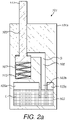
- a housing 101a of a mixer system 101 for a non-contact printer (not shown) comprises a reservoir 103 containing a liquid L, in this embodiment a reagent including biological cells.
- An upper portion of the reservoir 103 comprises three sections 103a-c, a central section 103b extending from the reservoir 103, through the housing 101a, to form an expansion chamber 105 which is in fluid connection with a cavity 107 also in the housing 101a.
- the expansion chamber 105 and cavity 107 contain a gas G, for example air.
- a passageway 109 extends from the cavity 107 to an opening at an edge of the housing 101a.
- a plunger or piston 111 has a head portion which is disposed in the cavity 107 and a body portion which extends through the passageway 109 and projects out of the opening at the edge of the housing 101a.
- the passageway 109 and cavity 107 together comprise a bore in which the piston 111 may slide.
- the body portion of the piston 111 provides a substantially gastight seal with the passageway 109, such that the gas G cannot escape from the housing 101a and ambient air cannot enter the housing 101a.
- a resilient element in this embodiment a spring 113, is provided in the cavity 107 and arranged to exert a force on the head portion of the piston 111 in order to bias the head portion of the piston 111 in a first position at one end of the cavity 107. With the piston 111 in this first position, the level of the liquid L is the same at all three sections 103a-c of the reservoir 103.
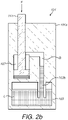
- a pushing force F is applied to the body portion of the piston 111 in order to overcome the resistance of the spring 113 and move the piston 111 along the bore until the head portion of the piston 111 reaches the limit of its travel at the other end of the cavity 107.
- the movement of the piston 111 causes a progressive increase in the volume, and fall in gas pressure, of the expansion chamber 105. Consequently, the pressure acting on the surface of the liquid L, at section 103b of the reservoir 103, is reduced. Accordingly, the pressure head of the liquid L causes the level of the liquid L to rise in the central section 103b, until a pressure equilibrium condition is achieved and the level settles.
- the liquid L is aspirated as the pressure in the expansion chamber 105 is reduced, by, in this embodiment, the reciprocating motion of the piston 111.
- the pushing force F is then removed, in a controlled manner, so that the piston 111 travels back along the bore under the biasing force exerted by the spring 113, until the piston 111 has returned to its original position as shown in Figure 2a .
- the piston 111 moves, the volume of the expansion chamber 105 is progressively reduced, and the gas pressure increased, so that the liquid L falls back to its original level.
- the cavity 107 is omitted and the piston 111 is arranged to reciprocate in the expansion chamber 105.
- the resilient element is arranged to bias the piston 111 in the opposite direction to that described hereinabove. Accordingly, a pulling force F may be applied to the body portion of the piston 111 against the resistance of the resilient element.
- the piston is omitted and instead the cavity 107 (or, alternatively, the expansion chamber 105) contains an inflatable element, in this embodiment an inflatable bag 311 (or, alternatively, a bellows or a diaphragm) in fluid communication with a valve 313 and an ambient air supply.
- an inflatable bag 311 or, alternatively, a bellows or a diaphragm in fluid communication with a valve 313 and an ambient air supply.
- the bag 311 has been filled with pressurised ambient air and the valve 313 has been closed, so that the level of the liquid L is the same at all three sections 103a-c of the reservoir 103.
- opening the valve 313 causes the bag 311 to deflate as the air escapes, leading to a progressive increase in the volume, and fall in gas pressure, of the expansion chamber 105. Consequently, the pressure acting on the surface of the liquid L, at section 103b of the reservoir 103, is reduced. Accordingly, the pressure head of the liquid L causes the level of the liquid L to rise in the central section 103b, until a pressure equilibrium condition is achieved and the level settles. Thus, the liquid L is aspirated as the pressure in the expansion chamber 105 is reduced, by, in this embodiment, the deflation of the bag 311.
- the bag 311 is then re-inflated and the valve 313 closed, in a controlled manner, so that the volume of the expansion chamber 105 is progressively reduced, and the gas pressure increased, so that the liquid L falls back to its original level.
- the aspirator element instead comprises a pump 411, arranged in fluid communication with the cavity 107.
- the pump is operated to suck the air from the cavity 107, leading to a progressive fall in gas pressure in the expansion chamber 105. Consequently, the pressure acting on the surface of the liquid L, at section 103b of the reservoir 103, is reduced.
- the pressure head of the liquid L causes the level of the liquid L to rise in the central section 103b of the reservoir 103, until a pressure equilibrium condition is achieved and the level settles.
- the liquid L is aspirated as the pressure in the expansion chamber 105 is reduced, by, in this embodiment, the vacuum effect of the pump 411.
- the pump is then activated to re-pressurise the cavity 107, in a controlled manner, so that the gas pressure of the expansion chamber 105 is progressively increased and the liquid L falls back to its original level.
- a flow induced in the liquid L by the aspiration action causes mild disturbance or agitation and thereby mixing of the liquid L in the reservoir 103, such that clumped cells are separated from one another, and/or heavier particles are disturbed and sedimentation at the bottom of the reservoir 103 is prevented, or at least reduced, without damaging the cells.
- the printer nozzle may be supplied, over time, with a stable cell concentration without degradation of cells.
- the liquid L has a volume of about 0.5 to 1.0 millilitre.
Landscapes
- Ink Jet (AREA)
- Apparatus Associated With Microorganisms And Enzymes (AREA)
Description
- The present invention relates to a mixer apparatus and system for a liquid. In a particular embodiment, the invention relates to a mixer apparatus and system for use with a non-contact liquid printer.
- Diagnostic testing of biological samples can be performed efficiently using multiplexed assays whereby multiple reagents may be printed in an array on a test substrate and subsequently exposed to a test sample for analysis. If it were possible to print reagents containing cells (or other particles) then the range of tests that may be performed could be significantly extended.
- Referring to
Figure 1 , a known non-contact printing apparatus 1, for example of the type described inWO-93/10910 fluid source 3 from which fluid is brought bycapillary feed 5 to therear face 9a of aperforate membrane 9 comprising a plurality ofnozzles 11. A vibration means oractuator 13 is operable by anelectronic circuit 15 which derives electrical power from apower supply 17 to vibrate theperforate membrane 9, producing droplets offluid 19 from thefront face 9b of theperforate membrane 9. Theactuator 13 comprises a piezoelectric and/or electrostrictive actuator, or a piezomagnetic or magnetostrictive actuator in combination with an electrical or magnetic field applied within at least part of the actuator material alternating at a selected frequency. Theactuator 13 may be formed as an element responsive by bending to an applied field. These forms of actuator can provide relatively large amplitudes of vibrational motion for a given size of actuator in response to a given applied alternating field. This relatively large motion may be transmitted through means bonding together regions of theactuator 13 and theperforate membrane 9 to provide correspondingly relatively large amplitudes of vibratory motion of theperforate membrane 9, so enhancing droplet dispensation. - Regarding the fluid source, it is typically the case that the cells (or other particles) will not be neutrally buoyant and so will sediment over time with resulting changes in homogeneity. If this is not addressed in a printing application it may result in a variation in cell concentration over time, which could cause an adverse impact on either the print performance or the reagent quality.
- An additional challenge with cells (and other types of biological material) is that they often have a tendency to adhere to each other, often forming 'clumps'. Also, cells are relatively delicate and prone to damage when exposed to mechanical shear (e.g. in pumping) and fluid volumes are very small; consequently external recirculation circuits are typically not possible. Interventions within the liquid reservoir to mix the cells may result in pressure disturbances which, in turn, could have an adverse impact on printing behaviour. The introduction of gas bubbles within the liquid has the potential to compromise printing behaviour and therefore mixing methods that include this risk are to be avoided.
- Current approaches to re-suspend cells typically involve re-circulation circuits, including a pump of some kind to create a flow within the reservoir and thereby induce mixing. Alternate approaches may include a rotating stirrer within the reservoir. Both of these approaches require a relatively large volume of liquid and are therefore not amenable to systems working with low liquid volumes. Additionally, these agitation methods induce shear within the liquid which can be problematic for some cell types, causing unwanted cell damage.
-
US 5 818 477 A discloses a system for non-contact printing with a printing liquid reservoir. - Accordingly, it would be beneficial to provide stable cell concentration in the region of the printer nozzle, over time, without degradation of cells.
- According to an aspect of the invention, there is provided a non-contact printing system according to accompanying claim 1.
- According to another aspect of the invention, there is provided a non-contact printing system according to accompanying
claim 3. - Appropriate printing liquids are reagents which may include DNA, proteins, antibodies, cells and cell fragments, other biological materials or particles, and other materials including suspensions. Liquid mixing is achieved through aspiration and subsequent dispense of a volume of liquid in the printing liquid reservoir, providing mixing of the liquid which prevents sedimentation without causing damage to the cells (or other particles) therein. "Mixing" and "mixer" as used herein refer to a disturbing or agitating action, which tends to separate cells (or other particles) which have adhered or 'clumped' together, and/or tends to cause re-suspension of cells (or other particles) in the liquid. The frequency of mixing may be substantially more frequent than the sedimentation time of cells in the liquid, but not so frequent as to "over-handle" (and possibly lyse) the cells. A range of about two to three minutes has been found to be appropriate.
- Embodiments will now be described, by way of example, with reference to the accompanying figures in which:
-
Figure 1 is a schematic depiction of a known non-contact printing apparatus; -
Figures 2a and2b show simplified, cross-sectional views of an embodiment of a mixer system in accordance with the invention; and -
Figures 3a to 4b show alternative embodiments of the mixer system. - Referring to
Figure 2a , ahousing 101a of amixer system 101 for a non-contact printer (not shown) comprises areservoir 103 containing a liquid L, in this embodiment a reagent including biological cells. An upper portion of thereservoir 103 comprises threesections 103a-c, acentral section 103b extending from thereservoir 103, through thehousing 101a, to form anexpansion chamber 105 which is in fluid connection with acavity 107 also in thehousing 101a. Theexpansion chamber 105 andcavity 107 contain a gas G, for example air. Apassageway 109 extends from thecavity 107 to an opening at an edge of thehousing 101a. - In this embodiment, a plunger or
piston 111 has a head portion which is disposed in thecavity 107 and a body portion which extends through thepassageway 109 and projects out of the opening at the edge of thehousing 101a. Thepassageway 109 andcavity 107 together comprise a bore in which thepiston 111 may slide. The body portion of thepiston 111 provides a substantially gastight seal with thepassageway 109, such that the gas G cannot escape from thehousing 101a and ambient air cannot enter thehousing 101a. - A resilient element, in this embodiment a
spring 113, is provided in thecavity 107 and arranged to exert a force on the head portion of thepiston 111 in order to bias the head portion of thepiston 111 in a first position at one end of thecavity 107. With thepiston 111 in this first position, the level of the liquid L is the same at all threesections 103a-c of thereservoir 103. - The operation of the
mixer apparatus 101 will now be described. Referring toFigure 2b , a pushing force F is applied to the body portion of thepiston 111 in order to overcome the resistance of thespring 113 and move thepiston 111 along the bore until the head portion of thepiston 111 reaches the limit of its travel at the other end of thecavity 107. The movement of thepiston 111 causes a progressive increase in the volume, and fall in gas pressure, of theexpansion chamber 105. Consequently, the pressure acting on the surface of the liquid L, atsection 103b of thereservoir 103, is reduced. Accordingly, the pressure head of the liquid L causes the level of the liquid L to rise in thecentral section 103b, until a pressure equilibrium condition is achieved and the level settles. Thus, the liquid L is aspirated as the pressure in theexpansion chamber 105 is reduced, by, in this embodiment, the reciprocating motion of thepiston 111. - The pushing force F is then removed, in a controlled manner, so that the
piston 111 travels back along the bore under the biasing force exerted by thespring 113, until thepiston 111 has returned to its original position as shown inFigure 2a . As thepiston 111 moves, the volume of theexpansion chamber 105 is progressively reduced, and the gas pressure increased, so that the liquid L falls back to its original level. - In an embodiment, the
cavity 107 is omitted and thepiston 111 is arranged to reciprocate in theexpansion chamber 105. - In an embodiment, the resilient element is arranged to bias the
piston 111 in the opposite direction to that described hereinabove. Accordingly, a pulling force F may be applied to the body portion of thepiston 111 against the resistance of the resilient element. - In an alternative embodiment, shown in
Figures 3a and3b , the piston is omitted and instead the cavity 107 (or, alternatively, the expansion chamber 105) contains an inflatable element, in this embodiment an inflatable bag 311 (or, alternatively, a bellows or a diaphragm) in fluid communication with avalve 313 and an ambient air supply. In the condition shown inFigure 3a , thebag 311 has been filled with pressurised ambient air and thevalve 313 has been closed, so that the level of the liquid L is the same at all threesections 103a-c of thereservoir 103. Referring toFigure 3b , opening thevalve 313 causes thebag 311 to deflate as the air escapes, leading to a progressive increase in the volume, and fall in gas pressure, of theexpansion chamber 105. Consequently, the pressure acting on the surface of the liquid L, atsection 103b of thereservoir 103, is reduced. Accordingly, the pressure head of the liquid L causes the level of the liquid L to rise in thecentral section 103b, until a pressure equilibrium condition is achieved and the level settles. Thus, the liquid L is aspirated as the pressure in theexpansion chamber 105 is reduced, by, in this embodiment, the deflation of thebag 311. - The
bag 311 is then re-inflated and thevalve 313 closed, in a controlled manner, so that the volume of theexpansion chamber 105 is progressively reduced, and the gas pressure increased, so that the liquid L falls back to its original level. - In another alternative embodiment, shown in
Figures 4a and4b , the aspirator element instead comprises apump 411, arranged in fluid communication with thecavity 107. In the condition shown inFigure 4a , ambient air has been pumped into the cavity 107 (or, alternatively, the expansion chamber 105) and the level of the liquid L is the same at all threesections 103a-c of thereservoir 103. Referring toFigure 4b , the pump is operated to suck the air from thecavity 107, leading to a progressive fall in gas pressure in theexpansion chamber 105. Consequently, the pressure acting on the surface of the liquid L, atsection 103b of thereservoir 103, is reduced. Accordingly, the pressure head of the liquid L causes the level of the liquid L to rise in thecentral section 103b of thereservoir 103, until a pressure equilibrium condition is achieved and the level settles. Thus, the liquid L is aspirated as the pressure in theexpansion chamber 105 is reduced, by, in this embodiment, the vacuum effect of thepump 411. - The pump is then activated to re-pressurise the
cavity 107, in a controlled manner, so that the gas pressure of theexpansion chamber 105 is progressively increased and the liquid L falls back to its original level. - In each of the above-described exemplary embodiments, a flow induced in the liquid L by the aspiration action causes mild disturbance or agitation and thereby mixing of the liquid L in the
reservoir 103, such that clumped cells are separated from one another, and/or heavier particles are disturbed and sedimentation at the bottom of thereservoir 103 is prevented, or at least reduced, without damaging the cells. Accordingly, the printer nozzle may be supplied, over time, with a stable cell concentration without degradation of cells. - In each of the above-described exemplary embodiments, the liquid L has a volume of about 0.5 to 1.0 millilitre.
- It will be understood that the invention has been described in relation to its preferred embodiments and may be modified in many different ways without departing from the scope of the invention as defined by the accompanying claims.
Claims (8)
- A non-contact printing system for printing biological materials, comprising:a printing liquid reservoir (103) containing a printing liquid (L), the printing liquid (L) having a volume of about 0.5 to 1.0 millilitres and comprising a reagent including cells or cell fragments or other biological particles, the printing liquid (L) defining a first printing liquid surface;an expansion chamber (105) in fluid communication with the printing liquid (L), the expansion chamber (105) including a bore; andan aspirator element in fluid communication with the expansion chamber (105), the aspirator element including a piston (111) arranged to reciprocate in the bore,wherein in use:the piston (111) is movable from a first position to a second position in order to increase the volume in the expansion chamber (105) so as to reduce a pressure of a gas (G) in the expansion chamber (105) which pressure acts on the first printing liquid surface, such that a pressure head of the printing liquid (L) moves the printing liquid (L) from the printing liquid reservoir (103) to the expansion chamber (105) to cause a second printing liquid surface defined by the expansion chamber (105) to rise in the expansion chamber (105) from a first level to a second level; andthe piston (111) is movable from the second position to the first position in order to reduce the volume in the expansion chamber (105) so as to restore the pressure of the gas (G) in the expansion chamber (105), such that the pressure head of the printing liquid (L) moves the printing liquid (L) from the expansion chamber (105) to the printing liquid reservoir (103) to return the second printing liquid surface from the second level to the first level,thereby to cause mixing of the printing liquid (L) in the printing liquid reservoir (103) by means of aspiration and subsequent dispense of a volume of the printing liquid (L) in the printing liquid reservoir (103), so as to provide a stable concentration of the cells or cell fragments or other biological particles for printing over time without degradation of the cells or cell fragments or other biological particles.
- A non-contact printing system according to claim 1, comprising:a housing (101a) containing the printing liquid reservoir (103) and a cavity (107); anda passageway (109) connecting the cavity (107) to an opening of the housing (101a) such that the passageway (109) and the cavity (107) together comprise the bore,wherein:the piston (111) forms a gas tight seal with the opening of the housing (101a);movement of the piston (111) from the first position to the second position opens the expansion chamber (105) to the cavity (107) in order to increase the volume to reduce the pressure of the gas (G) in the expansion chamber (105); andmovement of the piston (111) from the second position to the first position closes the expansion chamber (105) to the cavity (107) in order to reduce the volume to restore the pressure of the gas (G) in the expansion chamber (105).
- A non-contact printing system for printing biological materials, comprising:a printing liquid reservoir (103) containing a printing liquid (L), the printing liquid (L) having a volume of about 0.5 to 1.0 millilitres and comprising a reagent including cells or cell fragments or other biological particles, the printing liquid (L) defining a first printing liquid surface;an expansion chamber (105) in fluid communication with the printing liquid (L), the expansion chamber (105) including a bore; andan aspirator element in fluid communication with the expansion chamber (105), the aspiration element including an inflatable element which is located in the expansion chamber (105) and configured to be selectively inflated and deflated by an air supply of the non-contact printing system,wherein in use:the inflatable element is adjustable from an inflated condition to a deflated condition to increase the volume of the expansion chamber (105) and reduce the pressure of the gas (G) in the expansion chamber (105) which pressure acts on the first printing liquid surface, such that a pressure head of the printing liquid moves the printing liquid (L) from the printing liquid reservoir (103) to the expansion chamber (105) to cause a second printing liquid surface defined by the expansion chamber (105) to rise in the expansion chamber (105) from a first level to a second level; andthe inflatable element is adjustable from the deflated condition to the inflated condition to reduce the volume of the expansion chamber (105) and restore the pressure of the gas (G) in the expansion chamber (105) such that the pressure head of the printing liquid moves the printing liquid (L) from the expansion chamber (105) to the printing liquid reservoir (103) returning the second printing liquid surface from the second level to the first level,thereby to cause mixing of the printing liquid (L) in the printing liquid reservoir (103) by means of aspiration and subsequent dispense of a volume of the printing liquid (L) in the printing liquid reservoir (103), so as to provide a stable concentration of the cells or cell fragments or other biological particles for printing over time without degradation of the cells or cell fragments or other biological particles.
- A non-contact printing system according to claim 3, comprising:a housing (101a), containing the printing liquid reservoir (103) and cavity (107) connected to the expansion chamber (105);a passageway (109) connecting the cavity (107) to an opening of the housing (101a); anda valve (313) connected to the opening of the housing (101a) and to an air supply of the non-contact printing system,wherein:the valve (313) is operable to adjust the inflatable element from the inflated condition to the deflated condition to increase the volume of the cavity (107) and reduce the pressure of the gas (G) in the expansion chamber (105); andthe valve (313) is further operable to adjust the inflatable element from the deflated condition to the inflated condition to reduce the volume of the cavity (107) and restore the pressure of the gas (G) in the expansion chamber (105).
- A non-contact printing system according to claim 3 or 4, wherein the inflatable element comprises an inflatable bag (311).
- A non-contact printing system according to claim 3 or 4, wherein the inflatable element comprises a bellows.
- A non-contact printing system according to claim 3 or 4, wherein the inflatable element comprises a diaphragm.
- A non-contact printing system according to any preceding claim, wherein in use said printing liquid (L) rises in the expansion chamber (105) at a rate of about 0.1 to 1.0 milliliters per second.
Applications Claiming Priority (3)
| Application Number | Priority Date | Filing Date | Title |
|---|---|---|---|
| GBGB1420265.9A GB201420265D0 (en) | 2014-11-14 | 2014-11-14 | Mixer apparatus and system |
| PCT/GB2015/053390 WO2016075448A1 (en) | 2014-11-14 | 2015-11-09 | Mixer apparatus and system |
| EP15794264.0A EP3218193B1 (en) | 2014-11-14 | 2015-11-09 | Mixer apparatus and system |
Related Parent Applications (2)
| Application Number | Title | Priority Date | Filing Date |
|---|---|---|---|
| EP15794264.0A Division EP3218193B1 (en) | 2014-11-14 | 2015-11-09 | Mixer apparatus and system |
| EP15794264.0A Division-Into EP3218193B1 (en) | 2014-11-14 | 2015-11-09 | Mixer apparatus and system |
Publications (2)
| Publication Number | Publication Date |
|---|---|
| EP3686019A1 EP3686019A1 (en) | 2020-07-29 |
| EP3686019B1 true EP3686019B1 (en) | 2022-12-28 |
Family
ID=52248363
Family Applications (2)
| Application Number | Title | Priority Date | Filing Date |
|---|---|---|---|
| EP15794264.0A Active EP3218193B1 (en) | 2014-11-14 | 2015-11-09 | Mixer apparatus and system |
| EP20162522.5A Active EP3686019B1 (en) | 2014-11-14 | 2015-11-09 | Non-contact printing system |
Family Applications Before (1)
| Application Number | Title | Priority Date | Filing Date |
|---|---|---|---|
| EP15794264.0A Active EP3218193B1 (en) | 2014-11-14 | 2015-11-09 | Mixer apparatus and system |
Country Status (4)
| Country | Link |
|---|---|
| US (2) | US10137698B2 (en) |
| EP (2) | EP3218193B1 (en) |
| GB (1) | GB201420265D0 (en) |
| WO (1) | WO2016075448A1 (en) |
Family Cites Families (12)
| Publication number | Priority date | Publication date | Assignee | Title |
|---|---|---|---|---|
| US3929071A (en) * | 1974-12-23 | 1975-12-30 | Ibm | Ink recirculating system for ink jet printing apparatus |
| US4383263A (en) * | 1980-05-20 | 1983-05-10 | Canon Kabushiki Kaisha | Liquid ejecting apparatus having a suction mechanism |
| CA2019290A1 (en) | 1990-01-12 | 1991-07-12 | Bruce Cowger | Pressure-sensitive accumulator for ink-jet pens |
| WO1992004986A2 (en) * | 1990-09-15 | 1992-04-02 | David Mitchell | Liquid delivery apparatus |
| AU665222B2 (en) | 1991-12-04 | 1995-12-21 | Technology Partnership Plc, The | Production of fluid droplets |
| US5818477A (en) * | 1994-04-29 | 1998-10-06 | Fullmer; Timothy S. | Image forming system and process using more than four color processing |
| GB0108927D0 (en) * | 2001-04-10 | 2001-05-30 | Newlands Technology Ltd | Actuator with hydraulics |
| JP4191972B2 (en) * | 2002-10-04 | 2008-12-03 | 株式会社リコー | Ink liquid mixing apparatus, ink liquid manufacturing apparatus, manufacturing method, cleaning method, ink manufactured by the manufacturing method, ink cartridge storing the ink, ink jet apparatus, image forming method, and image formed product |
| EP2200834B1 (en) * | 2007-10-12 | 2013-07-17 | Videojet Technologies Inc. | Filter for ink supply system |
| JP2010069846A (en) * | 2008-09-22 | 2010-04-02 | Seiko Epson Corp | Liquid feeding device, and printing device |
| JP2013129184A (en) * | 2011-11-21 | 2013-07-04 | Ricoh Co Ltd | Image forming apparatus |
| KR20160036619A (en) * | 2013-07-31 | 2016-04-04 | 오가노보, 인크. | Automated devices, systems, and methods for the fabrication of tissue |
-
2014
- 2014-11-14 GB GBGB1420265.9A patent/GB201420265D0/en not_active Ceased
-
2015
- 2015-11-09 EP EP15794264.0A patent/EP3218193B1/en active Active
- 2015-11-09 EP EP20162522.5A patent/EP3686019B1/en active Active
- 2015-11-09 WO PCT/GB2015/053390 patent/WO2016075448A1/en not_active Ceased
- 2015-11-09 US US15/526,470 patent/US10137698B2/en active Active
-
2018
- 2018-10-23 US US16/167,913 patent/US10525724B2/en active Active
Also Published As
| Publication number | Publication date |
|---|---|
| WO2016075448A1 (en) | 2016-05-19 |
| US20170326886A1 (en) | 2017-11-16 |
| US10137698B2 (en) | 2018-11-27 |
| GB201420265D0 (en) | 2014-12-31 |
| US10525724B2 (en) | 2020-01-07 |
| EP3686019A1 (en) | 2020-07-29 |
| US20190160828A1 (en) | 2019-05-30 |
| EP3218193A1 (en) | 2017-09-20 |
| EP3218193B1 (en) | 2020-04-22 |
Similar Documents
| Publication | Publication Date | Title |
|---|---|---|
| Laurell et al. | Design and development of a silicon microfabricated flow-through dispenser for on-line picolitre sample handling | |
| CN101663097B (en) | Micromachined fluid ejector | |
| US20100120130A1 (en) | Droplet Actuator with Droplet Retention Structures | |
| US20020168297A1 (en) | Method and device for dispensing of droplets | |
| US8784749B2 (en) | Digital microfluidic manipulation device and manipulation method thereof | |
| US20070020763A1 (en) | Method, device, and computer program product for classifying a liquid | |
| JP7515549B2 (en) | Droplet Dispensing System | |
| JPWO2009008236A1 (en) | Micro inspection chip liquid mixing method and inspection apparatus | |
| US20090223012A1 (en) | Liquid suction device | |
| WO2013167584A1 (en) | Microfluidic dispenser, cartridge and analysis system for analyzing a biological sample | |
| Fan et al. | Encapsulated droplets with metered and removable oil shells by electrowetting and dielectrophoresis | |
| EP3827990B1 (en) | Liquid ejection unit and liquid ejection device | |
| US11001072B2 (en) | Liquid discharge head, liquid discharge device, dispensing device, and liquid discharge method | |
| JP2001132646A (en) | Diaphragm pump | |
| US10525724B2 (en) | Mixer apparatus and system | |
| US10010884B1 (en) | Droplet actuation enhancement using oscillatory sliding motion between substrates in microfluidic devices | |
| JP2009115732A (en) | Micro-inspection chip, method for micro-inspection chip to determine quantity of a liquid, and inspection method | |
| EP1385629A2 (en) | A method and device for dispensing of droplets | |
| JP2008076275A (en) | Dispensing device | |
| Duan et al. | A facile method for microfluidic metering and transport | |
| US20100086416A1 (en) | Thermo-pneumatic peristaltic pump | |
| EP2705899A1 (en) | A microfluidic system comprising a homogenizing component | |
| JP2009019890A (en) | Micro inspection chip and inspection device | |
| JPWO2009022496A1 (en) | Micro inspection chip and inspection device | |
| JP2008122234A (en) | Micro-integrated analysis chip and micro-integrated analysis system |
Legal Events
| Date | Code | Title | Description |
|---|---|---|---|
| PUAI | Public reference made under article 153(3) epc to a published international application that has entered the european phase |
Free format text: ORIGINAL CODE: 0009012 |
|
| STAA | Information on the status of an ep patent application or granted ep patent |
Free format text: STATUS: THE APPLICATION HAS BEEN PUBLISHED |
|
| AC | Divisional application: reference to earlier application |
Ref document number: 3218193 Country of ref document: EP Kind code of ref document: P |
|
| AK | Designated contracting states |
Kind code of ref document: A1 Designated state(s): AL AT BE BG CH CY CZ DE DK EE ES FI FR GB GR HR HU IE IS IT LI LT LU LV MC MK MT NL NO PL PT RO RS SE SI SK SM TR |
|
| STAA | Information on the status of an ep patent application or granted ep patent |
Free format text: STATUS: REQUEST FOR EXAMINATION WAS MADE |
|
| 17P | Request for examination filed |
Effective date: 20210126 |
|
| RBV | Designated contracting states (corrected) |
Designated state(s): AL AT BE BG CH CY CZ DE DK EE ES FI FR GB GR HR HU IE IS IT LI LT LU LV MC MK MT NL NO PL PT RO RS SE SI SK SM TR |
|
| GRAP | Despatch of communication of intention to grant a patent |
Free format text: ORIGINAL CODE: EPIDOSNIGR1 |
|
| STAA | Information on the status of an ep patent application or granted ep patent |
Free format text: STATUS: GRANT OF PATENT IS INTENDED |
|
| INTG | Intention to grant announced |
Effective date: 20220712 |
|
| GRAS | Grant fee paid |
Free format text: ORIGINAL CODE: EPIDOSNIGR3 |
|
| GRAA | (expected) grant |
Free format text: ORIGINAL CODE: 0009210 |
|
| STAA | Information on the status of an ep patent application or granted ep patent |
Free format text: STATUS: THE PATENT HAS BEEN GRANTED |
|
| RAP3 | Party data changed (applicant data changed or rights of an application transferred) |
Owner name: TTP PLC |
|
| AC | Divisional application: reference to earlier application |
Ref document number: 3218193 Country of ref document: EP Kind code of ref document: P |
|
| AK | Designated contracting states |
Kind code of ref document: B1 Designated state(s): AL AT BE BG CH CY CZ DE DK EE ES FI FR GB GR HR HU IE IS IT LI LT LU LV MC MK MT NL NO PL PT RO RS SE SI SK SM TR |
|
| REG | Reference to a national code |
Ref country code: GB Ref legal event code: FG4D |
|
| REG | Reference to a national code |
Ref country code: CH Ref legal event code: EP |
|
| REG | Reference to a national code |
Ref country code: DE Ref legal event code: R096 Ref document number: 602015082144 Country of ref document: DE |
|
| REG | Reference to a national code |
Ref country code: AT Ref legal event code: REF Ref document number: 1540219 Country of ref document: AT Kind code of ref document: T Effective date: 20230115 |
|
| REG | Reference to a national code |
Ref country code: IE Ref legal event code: FG4D |
|
| REG | Reference to a national code |
Ref country code: LT Ref legal event code: MG9D |
|
| PG25 | Lapsed in a contracting state [announced via postgrant information from national office to epo] |
Ref country code: SE Free format text: LAPSE BECAUSE OF FAILURE TO SUBMIT A TRANSLATION OF THE DESCRIPTION OR TO PAY THE FEE WITHIN THE PRESCRIBED TIME-LIMIT Effective date: 20221228 Ref country code: NO Free format text: LAPSE BECAUSE OF FAILURE TO SUBMIT A TRANSLATION OF THE DESCRIPTION OR TO PAY THE FEE WITHIN THE PRESCRIBED TIME-LIMIT Effective date: 20230328 Ref country code: LT Free format text: LAPSE BECAUSE OF FAILURE TO SUBMIT A TRANSLATION OF THE DESCRIPTION OR TO PAY THE FEE WITHIN THE PRESCRIBED TIME-LIMIT Effective date: 20221228 Ref country code: FI Free format text: LAPSE BECAUSE OF FAILURE TO SUBMIT A TRANSLATION OF THE DESCRIPTION OR TO PAY THE FEE WITHIN THE PRESCRIBED TIME-LIMIT Effective date: 20221228 |
|
| REG | Reference to a national code |
Ref country code: NL Ref legal event code: MP Effective date: 20221228 |
|
| REG | Reference to a national code |
Ref country code: AT Ref legal event code: MK05 Ref document number: 1540219 Country of ref document: AT Kind code of ref document: T Effective date: 20221228 |
|
| PG25 | Lapsed in a contracting state [announced via postgrant information from national office to epo] |
Ref country code: RS Free format text: LAPSE BECAUSE OF FAILURE TO SUBMIT A TRANSLATION OF THE DESCRIPTION OR TO PAY THE FEE WITHIN THE PRESCRIBED TIME-LIMIT Effective date: 20221228 Ref country code: LV Free format text: LAPSE BECAUSE OF FAILURE TO SUBMIT A TRANSLATION OF THE DESCRIPTION OR TO PAY THE FEE WITHIN THE PRESCRIBED TIME-LIMIT Effective date: 20221228 Ref country code: HR Free format text: LAPSE BECAUSE OF FAILURE TO SUBMIT A TRANSLATION OF THE DESCRIPTION OR TO PAY THE FEE WITHIN THE PRESCRIBED TIME-LIMIT Effective date: 20221228 Ref country code: GR Free format text: LAPSE BECAUSE OF FAILURE TO SUBMIT A TRANSLATION OF THE DESCRIPTION OR TO PAY THE FEE WITHIN THE PRESCRIBED TIME-LIMIT Effective date: 20230329 |
|
| PG25 | Lapsed in a contracting state [announced via postgrant information from national office to epo] |
Ref country code: NL Free format text: LAPSE BECAUSE OF FAILURE TO SUBMIT A TRANSLATION OF THE DESCRIPTION OR TO PAY THE FEE WITHIN THE PRESCRIBED TIME-LIMIT Effective date: 20221228 |
|
| P01 | Opt-out of the competence of the unified patent court (upc) registered |
Effective date: 20230526 |
|
| PG25 | Lapsed in a contracting state [announced via postgrant information from national office to epo] |
Ref country code: SM Free format text: LAPSE BECAUSE OF FAILURE TO SUBMIT A TRANSLATION OF THE DESCRIPTION OR TO PAY THE FEE WITHIN THE PRESCRIBED TIME-LIMIT Effective date: 20221228 Ref country code: RO Free format text: LAPSE BECAUSE OF FAILURE TO SUBMIT A TRANSLATION OF THE DESCRIPTION OR TO PAY THE FEE WITHIN THE PRESCRIBED TIME-LIMIT Effective date: 20221228 Ref country code: PT Free format text: LAPSE BECAUSE OF FAILURE TO SUBMIT A TRANSLATION OF THE DESCRIPTION OR TO PAY THE FEE WITHIN THE PRESCRIBED TIME-LIMIT Effective date: 20230428 Ref country code: ES Free format text: LAPSE BECAUSE OF FAILURE TO SUBMIT A TRANSLATION OF THE DESCRIPTION OR TO PAY THE FEE WITHIN THE PRESCRIBED TIME-LIMIT Effective date: 20221228 Ref country code: EE Free format text: LAPSE BECAUSE OF FAILURE TO SUBMIT A TRANSLATION OF THE DESCRIPTION OR TO PAY THE FEE WITHIN THE PRESCRIBED TIME-LIMIT Effective date: 20221228 Ref country code: CZ Free format text: LAPSE BECAUSE OF FAILURE TO SUBMIT A TRANSLATION OF THE DESCRIPTION OR TO PAY THE FEE WITHIN THE PRESCRIBED TIME-LIMIT Effective date: 20221228 Ref country code: AT Free format text: LAPSE BECAUSE OF FAILURE TO SUBMIT A TRANSLATION OF THE DESCRIPTION OR TO PAY THE FEE WITHIN THE PRESCRIBED TIME-LIMIT Effective date: 20221228 |
|
| PG25 | Lapsed in a contracting state [announced via postgrant information from national office to epo] |
Ref country code: SK Free format text: LAPSE BECAUSE OF FAILURE TO SUBMIT A TRANSLATION OF THE DESCRIPTION OR TO PAY THE FEE WITHIN THE PRESCRIBED TIME-LIMIT Effective date: 20221228 Ref country code: PL Free format text: LAPSE BECAUSE OF FAILURE TO SUBMIT A TRANSLATION OF THE DESCRIPTION OR TO PAY THE FEE WITHIN THE PRESCRIBED TIME-LIMIT Effective date: 20221228 Ref country code: IS Free format text: LAPSE BECAUSE OF FAILURE TO SUBMIT A TRANSLATION OF THE DESCRIPTION OR TO PAY THE FEE WITHIN THE PRESCRIBED TIME-LIMIT Effective date: 20230428 Ref country code: AL Free format text: LAPSE BECAUSE OF FAILURE TO SUBMIT A TRANSLATION OF THE DESCRIPTION OR TO PAY THE FEE WITHIN THE PRESCRIBED TIME-LIMIT Effective date: 20221228 |
|
| REG | Reference to a national code |
Ref country code: DE Ref legal event code: R097 Ref document number: 602015082144 Country of ref document: DE |
|
| PG25 | Lapsed in a contracting state [announced via postgrant information from national office to epo] |
Ref country code: DK Free format text: LAPSE BECAUSE OF FAILURE TO SUBMIT A TRANSLATION OF THE DESCRIPTION OR TO PAY THE FEE WITHIN THE PRESCRIBED TIME-LIMIT Effective date: 20221228 |
|
| PLBE | No opposition filed within time limit |
Free format text: ORIGINAL CODE: 0009261 |
|
| STAA | Information on the status of an ep patent application or granted ep patent |
Free format text: STATUS: NO OPPOSITION FILED WITHIN TIME LIMIT |
|
| 26N | No opposition filed |
Effective date: 20230929 |
|
| PG25 | Lapsed in a contracting state [announced via postgrant information from national office to epo] |
Ref country code: SI Free format text: LAPSE BECAUSE OF FAILURE TO SUBMIT A TRANSLATION OF THE DESCRIPTION OR TO PAY THE FEE WITHIN THE PRESCRIBED TIME-LIMIT Effective date: 20221228 |
|
| PG25 | Lapsed in a contracting state [announced via postgrant information from national office to epo] |
Ref country code: IT Free format text: LAPSE BECAUSE OF FAILURE TO SUBMIT A TRANSLATION OF THE DESCRIPTION OR TO PAY THE FEE WITHIN THE PRESCRIBED TIME-LIMIT Effective date: 20221228 |
|
| PG25 | Lapsed in a contracting state [announced via postgrant information from national office to epo] |
Ref country code: MC Free format text: LAPSE BECAUSE OF FAILURE TO SUBMIT A TRANSLATION OF THE DESCRIPTION OR TO PAY THE FEE WITHIN THE PRESCRIBED TIME-LIMIT Effective date: 20221228 |
|
| PG25 | Lapsed in a contracting state [announced via postgrant information from national office to epo] |
Ref country code: LU Free format text: LAPSE BECAUSE OF NON-PAYMENT OF DUE FEES Effective date: 20231109 |
|
| PG25 | Lapsed in a contracting state [announced via postgrant information from national office to epo] |
Ref country code: MC Free format text: LAPSE BECAUSE OF FAILURE TO SUBMIT A TRANSLATION OF THE DESCRIPTION OR TO PAY THE FEE WITHIN THE PRESCRIBED TIME-LIMIT Effective date: 20221228 Ref country code: LU Free format text: LAPSE BECAUSE OF NON-PAYMENT OF DUE FEES Effective date: 20231109 |
|
| REG | Reference to a national code |
Ref country code: BE Ref legal event code: MM Effective date: 20231130 |
|
| REG | Reference to a national code |
Ref country code: IE Ref legal event code: MM4A |
|
| PG25 | Lapsed in a contracting state [announced via postgrant information from national office to epo] |
Ref country code: IE Free format text: LAPSE BECAUSE OF NON-PAYMENT OF DUE FEES Effective date: 20231109 |
|
| PG25 | Lapsed in a contracting state [announced via postgrant information from national office to epo] |
Ref country code: BE Free format text: LAPSE BECAUSE OF NON-PAYMENT OF DUE FEES Effective date: 20231130 |
|
| PG25 | Lapsed in a contracting state [announced via postgrant information from national office to epo] |
Ref country code: IE Free format text: LAPSE BECAUSE OF NON-PAYMENT OF DUE FEES Effective date: 20231109 Ref country code: BE Free format text: LAPSE BECAUSE OF NON-PAYMENT OF DUE FEES Effective date: 20231130 |
|
| PG25 | Lapsed in a contracting state [announced via postgrant information from national office to epo] |
Ref country code: BG Free format text: LAPSE BECAUSE OF FAILURE TO SUBMIT A TRANSLATION OF THE DESCRIPTION OR TO PAY THE FEE WITHIN THE PRESCRIBED TIME-LIMIT Effective date: 20221228 |
|
| PG25 | Lapsed in a contracting state [announced via postgrant information from national office to epo] |
Ref country code: BG Free format text: LAPSE BECAUSE OF FAILURE TO SUBMIT A TRANSLATION OF THE DESCRIPTION OR TO PAY THE FEE WITHIN THE PRESCRIBED TIME-LIMIT Effective date: 20221228 |
|
| PG25 | Lapsed in a contracting state [announced via postgrant information from national office to epo] |
Ref country code: CY Free format text: LAPSE BECAUSE OF FAILURE TO SUBMIT A TRANSLATION OF THE DESCRIPTION OR TO PAY THE FEE WITHIN THE PRESCRIBED TIME-LIMIT; INVALID AB INITIO Effective date: 20151109 |
|
| PG25 | Lapsed in a contracting state [announced via postgrant information from national office to epo] |
Ref country code: HU Free format text: LAPSE BECAUSE OF FAILURE TO SUBMIT A TRANSLATION OF THE DESCRIPTION OR TO PAY THE FEE WITHIN THE PRESCRIBED TIME-LIMIT; INVALID AB INITIO Effective date: 20151109 |
|
| REG | Reference to a national code |
Ref country code: CH Ref legal event code: U11 Free format text: ST27 STATUS EVENT CODE: U-0-0-U10-U11 (AS PROVIDED BY THE NATIONAL OFFICE) Effective date: 20251201 |
|
| PG25 | Lapsed in a contracting state [announced via postgrant information from national office to epo] |
Ref country code: TR Free format text: LAPSE BECAUSE OF FAILURE TO SUBMIT A TRANSLATION OF THE DESCRIPTION OR TO PAY THE FEE WITHIN THE PRESCRIBED TIME-LIMIT Effective date: 20221228 |
|
| PGFP | Annual fee paid to national office [announced via postgrant information from national office to epo] |
Ref country code: DE Payment date: 20251128 Year of fee payment: 11 |
|
| PGFP | Annual fee paid to national office [announced via postgrant information from national office to epo] |
Ref country code: GB Payment date: 20251127 Year of fee payment: 11 |
|
| PGFP | Annual fee paid to national office [announced via postgrant information from national office to epo] |
Ref country code: FR Payment date: 20251125 Year of fee payment: 11 |
|
| PGFP | Annual fee paid to national office [announced via postgrant information from national office to epo] |
Ref country code: CH Payment date: 20251201 Year of fee payment: 11 |