EP3685983A1 - Apparatus for outline measurements of moving objects - Google Patents
Apparatus for outline measurements of moving objects Download PDFInfo
- Publication number
- EP3685983A1 EP3685983A1 EP19000150.3A EP19000150A EP3685983A1 EP 3685983 A1 EP3685983 A1 EP 3685983A1 EP 19000150 A EP19000150 A EP 19000150A EP 3685983 A1 EP3685983 A1 EP 3685983A1
- Authority
- EP
- European Patent Office
- Prior art keywords
- radiation
- devices
- measuring zone
- cable
- objects
- Prior art date
- Legal status (The legal status is an assumption and is not a legal conclusion. Google has not performed a legal analysis and makes no representation as to the accuracy of the status listed.)
- Pending
Links
- 238000005259 measurement Methods 0.000 title abstract description 28
- 230000005855 radiation Effects 0.000 claims abstract description 33
- 238000000034 method Methods 0.000 claims description 10
- 238000003384 imaging method Methods 0.000 claims description 3
- 238000004458 analytical method Methods 0.000 claims description 2
- 238000012544 monitoring process Methods 0.000 claims description 2
- 238000001125 extrusion Methods 0.000 description 7
- 238000004519 manufacturing process Methods 0.000 description 7
- 230000003287 optical effect Effects 0.000 description 7
- 239000004020 conductor Substances 0.000 description 4
- RYGMFSIKBFXOCR-UHFFFAOYSA-N Copper Chemical compound [Cu] RYGMFSIKBFXOCR-UHFFFAOYSA-N 0.000 description 2
- 229910052802 copper Inorganic materials 0.000 description 2
- 239000010949 copper Substances 0.000 description 2
- 238000012937 correction Methods 0.000 description 2
- 239000011248 coating agent Substances 0.000 description 1
- 238000000576 coating method Methods 0.000 description 1
- 238000004891 communication Methods 0.000 description 1
- 238000013461 design Methods 0.000 description 1
- 230000000694 effects Effects 0.000 description 1
- 239000011810 insulating material Substances 0.000 description 1
- 238000009413 insulation Methods 0.000 description 1
- 238000012360 testing method Methods 0.000 description 1
- 230000003245 working effect Effects 0.000 description 1
Images



Classifications
-
- G—PHYSICS
- G01—MEASURING; TESTING
- G01B—MEASURING LENGTH, THICKNESS OR SIMILAR LINEAR DIMENSIONS; MEASURING ANGLES; MEASURING AREAS; MEASURING IRREGULARITIES OF SURFACES OR CONTOURS
- G01B11/00—Measuring arrangements characterised by the use of optical techniques
- G01B11/24—Measuring arrangements characterised by the use of optical techniques for measuring contours or curvatures
-
- B—PERFORMING OPERATIONS; TRANSPORTING
- B29—WORKING OF PLASTICS; WORKING OF SUBSTANCES IN A PLASTIC STATE IN GENERAL
- B29C—SHAPING OR JOINING OF PLASTICS; SHAPING OF MATERIAL IN A PLASTIC STATE, NOT OTHERWISE PROVIDED FOR; AFTER-TREATMENT OF THE SHAPED PRODUCTS, e.g. REPAIRING
- B29C48/00—Extrusion moulding, i.e. expressing the moulding material through a die or nozzle which imparts the desired form; Apparatus therefor
- B29C48/15—Extrusion moulding, i.e. expressing the moulding material through a die or nozzle which imparts the desired form; Apparatus therefor incorporating preformed parts or layers, e.g. extrusion moulding around inserts
- B29C48/154—Coating solid articles, i.e. non-hollow articles
-
- B—PERFORMING OPERATIONS; TRANSPORTING
- B29—WORKING OF PLASTICS; WORKING OF SUBSTANCES IN A PLASTIC STATE IN GENERAL
- B29C—SHAPING OR JOINING OF PLASTICS; SHAPING OF MATERIAL IN A PLASTIC STATE, NOT OTHERWISE PROVIDED FOR; AFTER-TREATMENT OF THE SHAPED PRODUCTS, e.g. REPAIRING
- B29C48/00—Extrusion moulding, i.e. expressing the moulding material through a die or nozzle which imparts the desired form; Apparatus therefor
- B29C48/15—Extrusion moulding, i.e. expressing the moulding material through a die or nozzle which imparts the desired form; Apparatus therefor incorporating preformed parts or layers, e.g. extrusion moulding around inserts
- B29C48/151—Coating hollow articles
-
- B—PERFORMING OPERATIONS; TRANSPORTING
- B29—WORKING OF PLASTICS; WORKING OF SUBSTANCES IN A PLASTIC STATE IN GENERAL
- B29C—SHAPING OR JOINING OF PLASTICS; SHAPING OF MATERIAL IN A PLASTIC STATE, NOT OTHERWISE PROVIDED FOR; AFTER-TREATMENT OF THE SHAPED PRODUCTS, e.g. REPAIRING
- B29C48/00—Extrusion moulding, i.e. expressing the moulding material through a die or nozzle which imparts the desired form; Apparatus therefor
- B29C48/25—Component parts, details or accessories; Auxiliary operations
- B29C48/30—Extrusion nozzles or dies
- B29C48/32—Extrusion nozzles or dies with annular openings, e.g. for forming tubular articles
- B29C48/34—Cross-head annular extrusion nozzles, i.e. for simultaneously receiving moulding material and the preform to be coated
-
- B—PERFORMING OPERATIONS; TRANSPORTING
- B29—WORKING OF PLASTICS; WORKING OF SUBSTANCES IN A PLASTIC STATE IN GENERAL
- B29C—SHAPING OR JOINING OF PLASTICS; SHAPING OF MATERIAL IN A PLASTIC STATE, NOT OTHERWISE PROVIDED FOR; AFTER-TREATMENT OF THE SHAPED PRODUCTS, e.g. REPAIRING
- B29C48/00—Extrusion moulding, i.e. expressing the moulding material through a die or nozzle which imparts the desired form; Apparatus therefor
- B29C48/25—Component parts, details or accessories; Auxiliary operations
- B29C48/92—Measuring, controlling or regulating
-
- G—PHYSICS
- G01—MEASURING; TESTING
- G01B—MEASURING LENGTH, THICKNESS OR SIMILAR LINEAR DIMENSIONS; MEASURING ANGLES; MEASURING AREAS; MEASURING IRREGULARITIES OF SURFACES OR CONTOURS
- G01B11/00—Measuring arrangements characterised by the use of optical techniques
- G01B11/08—Measuring arrangements characterised by the use of optical techniques for measuring diameters
-
- G—PHYSICS
- G01—MEASURING; TESTING
- G01B—MEASURING LENGTH, THICKNESS OR SIMILAR LINEAR DIMENSIONS; MEASURING ANGLES; MEASURING AREAS; MEASURING IRREGULARITIES OF SURFACES OR CONTOURS
- G01B11/00—Measuring arrangements characterised by the use of optical techniques
- G01B11/24—Measuring arrangements characterised by the use of optical techniques for measuring contours or curvatures
- G01B11/2433—Measuring arrangements characterised by the use of optical techniques for measuring contours or curvatures for measuring outlines by shadow casting
-
- G—PHYSICS
- G01—MEASURING; TESTING
- G01B—MEASURING LENGTH, THICKNESS OR SIMILAR LINEAR DIMENSIONS; MEASURING ANGLES; MEASURING AREAS; MEASURING IRREGULARITIES OF SURFACES OR CONTOURS
- G01B11/00—Measuring arrangements characterised by the use of optical techniques
- G01B11/24—Measuring arrangements characterised by the use of optical techniques for measuring contours or curvatures
- G01B11/245—Measuring arrangements characterised by the use of optical techniques for measuring contours or curvatures using a plurality of fixed, simultaneously operating transducers
-
- B—PERFORMING OPERATIONS; TRANSPORTING
- B29—WORKING OF PLASTICS; WORKING OF SUBSTANCES IN A PLASTIC STATE IN GENERAL
- B29C—SHAPING OR JOINING OF PLASTICS; SHAPING OF MATERIAL IN A PLASTIC STATE, NOT OTHERWISE PROVIDED FOR; AFTER-TREATMENT OF THE SHAPED PRODUCTS, e.g. REPAIRING
- B29C2948/00—Indexing scheme relating to extrusion moulding
- B29C2948/92—Measuring, controlling or regulating
- B29C2948/92009—Measured parameter
- B29C2948/92114—Dimensions
- B29C2948/92123—Diameter or circumference
-
- B—PERFORMING OPERATIONS; TRANSPORTING
- B29—WORKING OF PLASTICS; WORKING OF SUBSTANCES IN A PLASTIC STATE IN GENERAL
- B29C—SHAPING OR JOINING OF PLASTICS; SHAPING OF MATERIAL IN A PLASTIC STATE, NOT OTHERWISE PROVIDED FOR; AFTER-TREATMENT OF THE SHAPED PRODUCTS, e.g. REPAIRING
- B29C2948/00—Indexing scheme relating to extrusion moulding
- B29C2948/92—Measuring, controlling or regulating
- B29C2948/92009—Measured parameter
- B29C2948/92114—Dimensions
- B29C2948/92152—Thickness
-
- B—PERFORMING OPERATIONS; TRANSPORTING
- B29—WORKING OF PLASTICS; WORKING OF SUBSTANCES IN A PLASTIC STATE IN GENERAL
- B29C—SHAPING OR JOINING OF PLASTICS; SHAPING OF MATERIAL IN A PLASTIC STATE, NOT OTHERWISE PROVIDED FOR; AFTER-TREATMENT OF THE SHAPED PRODUCTS, e.g. REPAIRING
- B29C2948/00—Indexing scheme relating to extrusion moulding
- B29C2948/92—Measuring, controlling or regulating
- B29C2948/92009—Measured parameter
- B29C2948/92114—Dimensions
- B29C2948/92171—Distortion, shrinkage, dilatation, swell or warpage
-
- B—PERFORMING OPERATIONS; TRANSPORTING
- B29—WORKING OF PLASTICS; WORKING OF SUBSTANCES IN A PLASTIC STATE IN GENERAL
- B29C—SHAPING OR JOINING OF PLASTICS; SHAPING OF MATERIAL IN A PLASTIC STATE, NOT OTHERWISE PROVIDED FOR; AFTER-TREATMENT OF THE SHAPED PRODUCTS, e.g. REPAIRING
- B29C2948/00—Indexing scheme relating to extrusion moulding
- B29C2948/92—Measuring, controlling or regulating
- B29C2948/92323—Location or phase of measurement
- B29C2948/92447—Moulded article
-
- B—PERFORMING OPERATIONS; TRANSPORTING
- B29—WORKING OF PLASTICS; WORKING OF SUBSTANCES IN A PLASTIC STATE IN GENERAL
- B29C—SHAPING OR JOINING OF PLASTICS; SHAPING OF MATERIAL IN A PLASTIC STATE, NOT OTHERWISE PROVIDED FOR; AFTER-TREATMENT OF THE SHAPED PRODUCTS, e.g. REPAIRING
- B29C48/00—Extrusion moulding, i.e. expressing the moulding material through a die or nozzle which imparts the desired form; Apparatus therefor
- B29C48/03—Extrusion moulding, i.e. expressing the moulding material through a die or nozzle which imparts the desired form; Apparatus therefor characterised by the shape of the extruded material at extrusion
- B29C48/06—Rod-shaped
-
- B—PERFORMING OPERATIONS; TRANSPORTING
- B29—WORKING OF PLASTICS; WORKING OF SUBSTANCES IN A PLASTIC STATE IN GENERAL
- B29C—SHAPING OR JOINING OF PLASTICS; SHAPING OF MATERIAL IN A PLASTIC STATE, NOT OTHERWISE PROVIDED FOR; AFTER-TREATMENT OF THE SHAPED PRODUCTS, e.g. REPAIRING
- B29C48/00—Extrusion moulding, i.e. expressing the moulding material through a die or nozzle which imparts the desired form; Apparatus therefor
- B29C48/03—Extrusion moulding, i.e. expressing the moulding material through a die or nozzle which imparts the desired form; Apparatus therefor characterised by the shape of the extruded material at extrusion
- B29C48/09—Articles with cross-sections having partially or fully enclosed cavities, e.g. pipes or channels
-
- B—PERFORMING OPERATIONS; TRANSPORTING
- B29—WORKING OF PLASTICS; WORKING OF SUBSTANCES IN A PLASTIC STATE IN GENERAL
- B29C—SHAPING OR JOINING OF PLASTICS; SHAPING OF MATERIAL IN A PLASTIC STATE, NOT OTHERWISE PROVIDED FOR; AFTER-TREATMENT OF THE SHAPED PRODUCTS, e.g. REPAIRING
- B29C48/00—Extrusion moulding, i.e. expressing the moulding material through a die or nozzle which imparts the desired form; Apparatus therefor
- B29C48/16—Articles comprising two or more components, e.g. co-extruded layers
Definitions
- the present invention is applicable to measurements of elongated objects which are produced by linear manufacturing methods, to determine the cross sectional external format and outline contour thereof.
- the fundamental measurement applied to linearly manufactured objects is the diameter or size of the object and this is achieved preferably by optical, non contact systems.
- Optical systems are also used to control the quality and outline contour condition of the objects, whereby the profile of an object is examined to ensure that there is no damage or faults, such as ridges valleys and the like, to the surface of the object.
- Cables cover a wide range of sizes, from small diameter communication types of a few millimeters, to large power cables of up 300 mm. diameters.
- All cables are manufactured in an extrusion process, in which a bare copper conductor is inserted in an extrusion machine which covers the bare conductor with an insulating material such as plastic or rubber. This is a continuous linear process, operating at speeds appropriate to the cable type.
- the cable has to be monitored and controlled, in order to maintain constant the overall diameter of the extruded cable, as required by the application and usage specifications of the cable type.
- Prior art describes optical devices which measure the diameter of cables during manufacture , in one, two, three or four planes. These devices can also operate in a rocking to / fro motion or indeed rotate around the cable in order to measure the overall cable circumference.
- An object of the present invention is to obviate drawbacks and problems of the prior art, by the use of optical measuring technics and apparatus operating at very high frequency levels, in order to provide accurate external format, outline contour condition , as well as diameter or size over the complete all round surface of elongated objects, during manufacturing process thereof.
- apparatus for non- contact measurement of the physical characteristics of elongated objects such as surface contour and dimensions, moving in an unguided linear process comprising a toroidal structure having an entrance aperture defining an internal measuring zone, a source of radiation within the toroidal structure configured by a multiplicity of radiation devices, disposed circumferentially around said toroidal structure within the measuring zone ,to provide a screen of radiation to envelop the object as it moves there through in said linear process , and a plurality of recording devices within the measuring zone, providing circumferential coverage overlap with said radiation devices and being adapted to analyze the imaging information of the emitted radiation from the object as it passes through said screen, representative of the physical characteristics of said object including its surface and dimensions.
- FIG. 1 of the drawings an embodiment of the measuring apparatus of the invention is shown in the form of a toroidal structure 1 having an entrance aperture P defining an internal measuring zone Z.
- An electric cable 2 under monitor is shown travelling through the entrance aperture P and the measuring zone Z of the toroidal structure 1 .
- a cross sectional view of the cable 2 under test is shown in Fig 2 having a copper conductor 2.1 of diameter (d) and an outer coating of plastic insulation 2,2 of overall diameter (D).
- the toroidal structure 1 is provided with a plurality of circumferentially mounted radiation emitting devices 3 more particularly shown in Fig 4 and 4A which form when in use, a screen of emitted radiation R enveloping the travelling cable 2.
- the radiation devices 3 provide a circumferential closed ring of individual pixels N enveloping the cable 2 with radiation R within the measuring zone Z.
- a plurality of image recording devices C such as CCD cameras and the like, are disposed in a closed circumferential ring longitudinally adjacent the radiation emitting devices 3 inside the toroidal structure 1, whereby the image recording devices C and radiation emitting devices 3 are provided with an unrestricted view of cable 2 at all times, during the operation of the invention.
- pixel N1 when pixel N1 and a recording device C1 are energized simultaneously, pixel N1 generates radiation of multiple rays R (see Fig 5 ), one of which RA, makes tangential contact with cable 1 at point 4 and proceeds to recording device C 1.
- Recording device C 1 measures the time lapse between, the contact of ray RA with cable 2 at point 4, to the contact of ray RB with cable 2 at point 5 .
- Fig 6 illustrates the feature of the invention, whereby recording devices C are adapted to identify and measure the time lapse between 2 successive rays R, such as said RA and RB, which have made tangential contact with cable 2.
- Fig 7 Shows a continuation of the above processes, whereby six consecutive rays R1 R2, R3 R4 and R5 R6 encircling cable 2 within the measuring zone Z, make tangential connections to cable 2 and proceed to recording devices C 1, C2, C3 respectively, thus providing a complete overlap over the surface of cable 2 to ensure a continuous uninterrupted surface coverage at all times, in order to achieve accurate measurements throughout the operation of the invention.
- the apparatus of the invention has an operational frequency rate of 3000 Hz (scans per second) to locate the position of the cable 2 within the aperture of measuring zone Z of the toroidal structure 1, and apply positional corrections to cable 2, in order to ensure that all measurements related to the cable 2 are accurate, irrespective of the position of cable 2 at any particular moment, within the aperture measuring zone Z .
- 3000 Hz scans per second
- the apparatus of the invention utilizes time related functions from recording devices C, to determine the time lapse between the sequential points of the tangential contacts of the rays R with the cable 2, around the circumference of the cable 2.
- a series of calculations are then performed to determine accurate measurements of the external format, outline contour condition and diameter or size of the cable 2 continuously, as the cable 2 moves freely unsupported vertically or horizontally within the aperture measuring zone Z, while being extruded and travelling at the same time in a linear motion.
- FIGS 8 (a)(b)(c)(d) illustrate in accordance with the prior art a single plane diameter measurement AA disposed at 180 degrees around the cable 2, a two plane diameter measurement AA+BB disposed at 90 degrees around the cable 2, a three plane AA + BB + CC diameter measurement, disposed at 120 degrees around the cable 2, and a four plane diameter measurement AA + BB + CC +DD disposed at 45 degrees around the cable 2.
- the advantage of present invention is that it has multiple plane capability as shown in Fig 8 (e) , whereby the apparatus performs diameter measurements on the cable 2 across an increased number of sections AA +BB+ CC +DD + FF ++ in contrast with the prior art, as it sweeps around the surface of cable 2 at the rate of 3,000 measurements per second, thereby to ensure continuous complete surface coverage of cable 2 .
- optical devices are able to operate in a rocking to and fro motion or full rotational motion around the moving cable.
- the invention as described in the preceding embodiments has the ability to provide control functions to the extrusion machines , whereby diameter deviations are used as feedback to effect speed adjustments to the extrusion machines , in order to maintain the preset diameter as required.
Landscapes
- Engineering & Computer Science (AREA)
- Physics & Mathematics (AREA)
- General Physics & Mathematics (AREA)
- Mechanical Engineering (AREA)
- Manufacturing & Machinery (AREA)
- Investigating Materials By The Use Of Optical Means Adapted For Particular Applications (AREA)
- Length Measuring Devices By Optical Means (AREA)
Abstract
Description
- The present invention is applicable to measurements of elongated objects which are produced by linear manufacturing methods, to determine the cross sectional external format and outline contour thereof.
- In the manufacture of objects of an elongated form such as wires, cables, ropes tubes, pipes, hoses and the like, there is a requirement to measure the external format and outline contour of these objects in order to confirm adherence to specific applications, maintain quality, as well as mechanical and or electrical specifications. In most cases, these measurements are applied when these objects are being produced in processes involving extrusion machines, in the case of plastic cables, hoses, tubes etc., or drawing machines in the case of wires, metallic tubes and the like.
- The fundamental measurement applied to linearly manufactured objects, is the diameter or size of the object and this is achieved preferably by optical, non contact systems. Optical systems are also used to control the quality and outline contour condition of the objects, whereby the profile of an object is examined to ensure that there is no damage or faults, such as ridges valleys and the like, to the surface of the object.
- Strict specification requirements apply to electric cables due to the fact they are current carrying conductors.
- Cables cover a wide range of sizes, from small diameter communication types of a few millimeters, to large power cables of up 300 mm. diameters.
- All cables are manufactured in an extrusion process, in which a bare copper conductor is inserted in an extrusion machine which covers the bare conductor with an insulating material such as plastic or rubber. This is a continuous linear process, operating at speeds appropriate to the cable type.
- During the above process, the cable has to be monitored and controlled, in order to maintain constant the overall diameter of the extruded cable, as required by the application and usage specifications of the cable type.
- Prior art describes optical devices which measure the diameter of cables during manufacture , in one, two, three or four planes. These devices can also operate in a rocking to / fro motion or indeed rotate around the cable in order to measure the overall cable circumference.
- It is to be noted, that due to the time taken to perform the rocking motion to/ fro, or the rotation around the cable on a linear
travelling cable, the results will be helical measurements , which are of limited use , mainly for general statistical or historical information. - An object of the present invention is to obviate drawbacks and problems of the prior art, by the use of optical measuring technics and apparatus operating at very high frequency levels, in order to provide accurate external format, outline contour condition , as well as diameter or size over the complete all round surface of elongated objects, during manufacturing process thereof.
- According to the invention there is provided apparatus for non- contact measurement of the physical characteristics of elongated objects such as surface contour and dimensions, moving in an unguided linear process comprising a toroidal structure having an entrance aperture defining an internal measuring zone, a source of radiation within the toroidal structure configured by a multiplicity of radiation devices, disposed circumferentially around said toroidal structure within the measuring zone ,to provide a screen of radiation to envelop the object as it moves there through in said linear process , and a plurality of recording devices within the measuring zone, providing circumferential coverage overlap with said radiation devices and being adapted to analyze the imaging information of the emitted radiation from the object as it passes through said screen, representative of the physical characteristics of said object including its surface and dimensions.
- In the following description of preferred embodiments of the invention reference will be made to cable extrusion
processes , which require a high degree of performance accuracy. - However this does not preclude in any way, the application and usage of the invention, to other types of measurement in the manufacture of elongated objects other than by extrusion.
- The invention will now be described by way of example with reference to the accompanying drawings wherein:
-
Fig 1 shows the toroidal structure of the invention in perspective view; -
Fig 2 shows a cross view of a typical cable to which the present invention may be employed as to measurement of physical characteristics thereof; -
Fig 3 shows the toroidal structure ofFig 1 in use monitoring a travelling cable; -
Fig 4 shows further features of the toroidal structure ofFig 1 ; -
Fig 4A shows specific design details of the toroidal structure ofFig 1 in cross sectional view along XX ofFig 4 . -
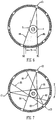
Figs 5, 5A ,6 and 7 are cross sectional views of the toroid structure ofFig 1 illustrating the workings of the invention. -
Fig 8 (a)(b)(c) and (d) depict alternative methods of measurement of the physical characteristics of a travelling object in accordance with the prior art whileFig 8(e) illustrates measurement in accordance with an embodiment of the invention - and
Fig 9 shows various cross sectional views of differing travelling objects which may be measured for physical characteristics by the apparatus of the invention - With reference to
Fig 1 of the drawings an embodiment of the measuring apparatus of the invention is shown in the form of atoroidal structure 1 having an entrance aperture P defining an internal measuring zone Z. - An
electric cable 2 under monitor is shown travelling through the entrance aperture P and the measuring zone Z of thetoroidal structure 1 . A cross sectional view of thecable 2 under test is shown inFig 2 having a copper conductor 2.1 of diameter (d) and an outer coating ofplastic insulation - As shown in
FIG 3 thetoroidal structure 1 is provided with a plurality of circumferentially mountedradiation emitting devices 3 more particularly shown inFig 4 and 4A which form when in use, a screen of emitted radiation R enveloping thetravelling cable 2. - As shown in
Fig 5 and Fig 5A theradiation devices 3 provide a circumferential closed ring of individual pixels N enveloping thecable 2 with radiation R within the measuring zone Z. - As shown in the cross sectional view of the
toroidal structure 1 inFig 4A a plurality of image recording devices C such as CCD cameras and the like, are disposed in a closed circumferential ring longitudinally adjacent theradiation emitting devices 3 inside thetoroidal structure 1, whereby the image recording devices C andradiation emitting devices 3 are provided with an unrestricted view ofcable 2 at all times, during the operation of the invention. - With reference to
Fig 5 , when the apparatus of the invention becomes functional, individual pixels N fromradiation devices 3 are energized sequentially, and generate a screen of radiation of rays R which sweep zone Z in a clockwise manner T and simultaneously, recording devices C are energized in conjunction with radiation rays R, in order to provide positional corrections and physical characteristics ofcable 2 within the measuring zone Z oftoroidal structure 1. - Thus with particular reference to
Fig 5A , when pixel N1 and a recording device C1 are energized simultaneously, pixel N1 generates radiation of multiple rays R (seeFig 5 ), one of which RA, makes tangential contact withcable 1 at point 4 and proceeds to recordingdevice C 1. - In a similar manner, when pixel N2 is energized it also generates rays R one of which , ray RB, makes tangential contact with
cable 2 atpoint 5, and also proceeds to recordingdevice C 1. -
Recording device C 1 measures the time lapse between, the contact of ray RA withcable 2 at point 4, to the contact of ray RB withcable 2 atpoint 5 .Fig 6 illustrates the feature of the invention, whereby recording devices C are adapted to identify and measure the time lapse between 2 successive rays R, such as said RA and RB, which have made tangential contact withcable 2. - Rays R generated from pixels N located between pixels N1 and N2 are blocked by
cable 2 and all other rays that have not made contact withcable 2 are rejected by recording devices C. -
Fig 7 Shows a continuation of the above processes, whereby six consecutive rays R1 R2, R3 R4 and R5R6 encircling cable 2 within the measuring zone Z, make tangential connections tocable 2 and proceed to recordingdevices C 1, C2, C3 respectively, thus providing a complete overlap over the surface ofcable 2 to ensure a continuous uninterrupted surface coverage at all times, in order to achieve accurate measurements throughout the operation of the invention. - The apparatus of the invention has an operational frequency rate of 3000 Hz (scans per second) to locate the position of the
cable 2 within the aperture of measuring zone Z of thetoroidal structure 1, and apply positional corrections tocable 2, in order to ensure that all measurements related to thecable 2 are accurate, irrespective of the position ofcable 2 at any particular moment, within the aperture measuring zone Z . - By imaging analysis the apparatus of the invention utilizes time related functions from recording devices C, to determine the time lapse between the sequential points of the tangential contacts of the rays R with the
cable 2, around the circumference of thecable 2. - A series of calculations are then performed to determine accurate measurements of the external format, outline contour condition and diameter or size of the
cable 2 continuously, as thecable 2 moves freely unsupported vertically or horizontally within the aperture measuring zone Z, while being extruded and travelling at the same time in a linear motion. - With reference to
FIGS 8 (a)(b)(c)(d) respectively, these illustrate in accordance with the prior art a
single plane diameter measurement AA disposed at 180 degrees around thecable 2, a two plane diameter measurement AA+BB disposed at 90 degrees around thecable 2, a three plane AA + BB + CC diameter measurement, disposed at 120 degrees around thecable 2, and a four plane diameter measurement AA + BB + CC +DD disposed at 45 degrees around thecable 2. - All the above measurements are performed at the same position or spot around the
cable 2. It will be obvious to the person familiar in the art, that there are sections between the spot measurements , around the surface of saidcable 2, that pass through the measuring zone Z without being measured. - The advantage of present invention is that it has multiple plane capability as shown in
Fig 8 (e) , whereby the apparatus performs diameter measurements on thecable 2 across an increased number of sections AA +BB+ CC +DD + FF ++ in contrast with the prior art, as it sweeps around the surface ofcable 2 at the rate of 3,000 measurements per second, thereby to ensure continuous complete surface coverage ofcable 2 . - An actual example will further demonstrate the advantage of the present invention.
- Let it be assumed that a cable manufacturing line is running at a speed of 600 m/min or 10 m/sec.
- As discussed earlier prior art optical devices are able to operate in a rocking to and fro motion or full rotational motion around the moving cable.
- Let it be assumed that such optical devices take 2 seconds to perform one circumferential revolution around the cable.
- In 2 seconds, the cable manufacturing line will produce 20 meters of cable. Therefore one circumferential rotation in a prior art optical device will spread out measurements in a helical form over a cable length of 20 meters.
- These measurements are of limited use, as mentioned previously in the discussion of the prior art.
- In contrast the apparatus according to the present invention will in 2 seconds take 2 x 3000 = 6,000 measurements.
- The cable length of the above example is 20 m= 20,000 mm and 20,000 / 6,000= 3.3 mm
- Therefore with the present invention one circumferential diameter measurement will take place every 3.3 mm of cable length, a considerable improvement over the prior art
- The invention as described in the preceding embodiments has the ability to provide control functions to the extrusion machines , whereby diameter deviations are used as feedback to effect speed adjustments to the extrusion machines , in order to maintain the preset diameter as required.
- Dimensional measurements as well as cross - section outlines of all linearly manufactured objects, may be displayed on screen displays in real time and surface or contour imperfections, may be recorded for quality and statistical purposes.
Claims (7)
- Apparatus for non- contact monitoring of travelling objects being produced in an unguided linear process, in order to determine their physical characteristics comprising a toroidal structure with an open aperture defining a measuring zone, a source of radiation configured by a plurality of radiation devices circumferentially disposed within the measuring zone whereby the radiation source emits rays which generate a planar screen of radiation across the object circumferentially to envelop said object within said measuring zone , a plurality of recording devices for receiving radiation from said radiation devices following interception of said rays by the objects in the measuring zone, said recording devices being circumferentially disposed in relation to said radiation devices and analysis means for analyzing imaging information of the emitted radiation recorded by said recording devices thereby to provide a measure of the physical characteristics of said object.
- Apparatus as claimed in Claim 1 wherein said recording devices are in the form of charged coupled devices.
- Apparatus as claimed in claim 2 wherein said radiation source is provided by a plurality of radiation emitting devices arranged in circumferential array in said measuring zone.
- Apparatus as claimed in claim 3 wherein said radiation emitting devices are formed in a closed circumferential ring around the measuring zone, and said charged coupled devices are disposed in a similar manner adjacent said radiation emitting devices.
- Apparatus as claimed in claim 4 wherein said radiation emitting devices and said charged coupled devices are arranged in side by side relationship around said measuring zone.
- Apparatus as claimed in any one of claims 2 through 5 including energizing means for energizing said radiation emitting devices sequentially to provide light rays which sweep said measuring zone thereby to generate said screen of radiation to scan the travelling objects.
- Apparatus as claimed in claim 6 wherein said energizing means energizes said recording devices simultaneously with energization of said charged coupled devices to enable the physical characteristics of the objects to be determined.
Applications Claiming Priority (1)
| Application Number | Priority Date | Filing Date | Title |
|---|---|---|---|
| GBGB1900914.1A GB201900914D0 (en) | 2019-01-23 | 2019-01-23 | Outline measurements of moving objects |
Publications (1)
| Publication Number | Publication Date |
|---|---|
| EP3685983A1 true EP3685983A1 (en) | 2020-07-29 |
Family
ID=65656048
Family Applications (1)
| Application Number | Title | Priority Date | Filing Date |
|---|---|---|---|
| EP19000150.3A Pending EP3685983A1 (en) | 2019-01-23 | 2019-03-27 | Apparatus for outline measurements of moving objects |
Country Status (3)
| Country | Link |
|---|---|
| US (1) | US10816329B2 (en) |
| EP (1) | EP3685983A1 (en) |
| GB (1) | GB201900914D0 (en) |
Citations (5)
| Publication number | Priority date | Publication date | Assignee | Title |
|---|---|---|---|---|
| GB2003693A (en) * | 1977-08-29 | 1979-03-14 | Semperit Ag | Optical determination of surface contours |
| EP0364907A2 (en) * | 1988-10-18 | 1990-04-25 | SMS Hasenclever GmbH | Process and device to determine the geometry of an object |
| GB2465024A (en) * | 2008-11-08 | 2010-05-12 | Adaptive Automation Ltd | Shadow sensing apparatus |
| DE102011119658A1 (en) * | 2011-11-29 | 2013-05-29 | SmartRay GmbH | Device for contactless, optical testing of roundness and straightness of pipeline tube, has evaluation unit in position to determine straightness of tube over whole length at circumferential position of straightness sensor |
| WO2015043554A1 (en) * | 2013-09-30 | 2015-04-02 | Vysoká Škola Báňská - Technická Univerzita Ostrava | A method of non-contact measuring of outer dimensions of cross sections of metallurgical rod material and a modular frame for performing thereof |
Family Cites Families (4)
| Publication number | Priority date | Publication date | Assignee | Title |
|---|---|---|---|---|
| US3626196A (en) * | 1969-11-04 | 1971-12-07 | Anaconda Wire & Cable Co | Radiation sensitive holiday detector for coated strands |
| BE1010882A5 (en) * | 1997-01-28 | 1999-02-02 | Barco Nv | A DETECTOR foreign fibers and foreign MATERIALS BASED ON ABSORPTION MEASUREMENT OF LIGHT AND SIMILAR DETECTION. |
| US7038779B2 (en) * | 2003-10-10 | 2006-05-02 | Ethicon Inc. | System and method for sensing variations in a strand |
| CN110455816A (en) * | 2012-12-10 | 2019-11-15 | 乌斯特技术股份公司 | Equipment for optical check moving textile material |
-
2019
- 2019-01-23 GB GBGB1900914.1A patent/GB201900914D0/en not_active Ceased
- 2019-03-20 US US16/359,111 patent/US10816329B2/en active Active
- 2019-03-27 EP EP19000150.3A patent/EP3685983A1/en active Pending
Patent Citations (5)
| Publication number | Priority date | Publication date | Assignee | Title |
|---|---|---|---|---|
| GB2003693A (en) * | 1977-08-29 | 1979-03-14 | Semperit Ag | Optical determination of surface contours |
| EP0364907A2 (en) * | 1988-10-18 | 1990-04-25 | SMS Hasenclever GmbH | Process and device to determine the geometry of an object |
| GB2465024A (en) * | 2008-11-08 | 2010-05-12 | Adaptive Automation Ltd | Shadow sensing apparatus |
| DE102011119658A1 (en) * | 2011-11-29 | 2013-05-29 | SmartRay GmbH | Device for contactless, optical testing of roundness and straightness of pipeline tube, has evaluation unit in position to determine straightness of tube over whole length at circumferential position of straightness sensor |
| WO2015043554A1 (en) * | 2013-09-30 | 2015-04-02 | Vysoká Škola Báňská - Technická Univerzita Ostrava | A method of non-contact measuring of outer dimensions of cross sections of metallurgical rod material and a modular frame for performing thereof |
Also Published As
| Publication number | Publication date |
|---|---|
| US20200232788A1 (en) | 2020-07-23 |
| GB201900914D0 (en) | 2019-03-13 |
| US10816329B2 (en) | 2020-10-27 |
Similar Documents
| Publication | Publication Date | Title |
|---|---|---|
| EP2752287B1 (en) | Apparatus for measuring industrial products manufactured by extrusion techniques | |
| CN111837011A (en) | Surface scanner, arrangement and method for surface defect detection of cables | |
| JP5360132B2 (en) | Superconducting wire inspection device and inspection method | |
| JPH0539407B2 (en) | ||
| EP3901571A1 (en) | Surface quality determination of a high voltage cable end | |
| US9733193B2 (en) | Measurement of industrial products manufactured by extrusion techniques | |
| JP2016170168A (en) | Measurement of industrial products manufactured by extrusion techniques | |
| GB2121956A (en) | Cross-section of non-circular filaments | |
| US20260092773A1 (en) | Method for inspecting surfaces and interfaces of high voltage cable components | |
| EP3685983A1 (en) | Apparatus for outline measurements of moving objects | |
| JP2024122910A (en) | Laser scanning of cables and cable accessory components subjected to mechanical loads and elastic or inelastic deformations | |
| RU2715364C1 (en) | Method for remote determination of corona discharge coordinates on a high-voltage power transmission line | |
| EP3078960B1 (en) | Apparatus and methods of inspecting a wire segment | |
| CN119604756A (en) | System and method for detecting defects in insulation of magnet wire | |
| US20250347634A1 (en) | Surface analysis of cable layer | |
| GB1600652A (en) | Testing devices for insulating sheaths | |
| US5764823A (en) | Optical switch for isolating multiple fiber optic strands | |
| US3760264A (en) | Method and device for measuring minima or maxima of the thickness of a dielectric layer on an electric conductor | |
| EP2902837B1 (en) | A high speed magnetic oscillating device | |
| EP0647951B1 (en) | Electrical cables | |
| US5550631A (en) | Insulation doping system for monitoring the condition of electrical insulation | |
| CN210015313U (en) | Industrial cable on-line detection panoramic photographic device | |
| JPH03284927A (en) | Foreign matter inspection device of plastic extruder | |
| GB2283323A (en) | Electrical cable insulation measurement | |
| JP7409648B2 (en) | Power cable inspection device and inspection method |
Legal Events
| Date | Code | Title | Description |
|---|---|---|---|
| PUAI | Public reference made under article 153(3) epc to a published international application that has entered the european phase |
Free format text: ORIGINAL CODE: 0009012 |
|
| STAA | Information on the status of an ep patent application or granted ep patent |
Free format text: STATUS: THE APPLICATION HAS BEEN PUBLISHED |
|
| AK | Designated contracting states |
Kind code of ref document: A1 Designated state(s): AL AT BE BG CH CY CZ DE DK EE ES FI FR GB GR HR HU IE IS IT LI LT LU LV MC MK MT NL NO PL PT RO RS SE SI SK SM TR |
|
| AX | Request for extension of the european patent |
Extension state: BA ME |
|
| STAA | Information on the status of an ep patent application or granted ep patent |
Free format text: STATUS: REQUEST FOR EXAMINATION WAS MADE |
|
| 17P | Request for examination filed |
Effective date: 20201227 |
|
| RBV | Designated contracting states (corrected) |
Designated state(s): AL AT BE BG CH CY CZ DE DK EE ES FI FR GB GR HR HU IE IS IT LI LT LU LV MC MK MT NL NO PL PT RO RS SE SI SK SM TR |
|
| STAA | Information on the status of an ep patent application or granted ep patent |
Free format text: STATUS: EXAMINATION IS IN PROGRESS |
|
| 17Q | First examination report despatched |
Effective date: 20211208 |