EP3685922B1 - Material sprayer - Google Patents
Material sprayer Download PDFInfo
- Publication number
- EP3685922B1 EP3685922B1 EP19205823.8A EP19205823A EP3685922B1 EP 3685922 B1 EP3685922 B1 EP 3685922B1 EP 19205823 A EP19205823 A EP 19205823A EP 3685922 B1 EP3685922 B1 EP 3685922B1
- Authority
- EP
- European Patent Office
- Prior art keywords
- hopper
- module
- pump
- power module
- frame portion
- Prior art date
- Legal status (The legal status is an assumption and is not a legal conclusion. Google has not performed a legal analysis and makes no representation as to the accuracy of the status listed.)
- Active
Links
Images












Classifications
-
- B—PERFORMING OPERATIONS; TRANSPORTING
- B05—SPRAYING OR ATOMISING IN GENERAL; APPLYING FLUENT MATERIALS TO SURFACES, IN GENERAL
- B05B—SPRAYING APPARATUS; ATOMISING APPARATUS; NOZZLES
- B05B7/00—Spraying apparatus for discharge of liquids or other fluent materials from two or more sources, e.g. of liquid and air, of powder and gas
- B05B7/02—Spray pistols; Apparatus for discharge
- B05B7/04—Spray pistols; Apparatus for discharge with arrangements for mixing liquids or other fluent materials before discharge
- B05B7/0416—Spray pistols; Apparatus for discharge with arrangements for mixing liquids or other fluent materials before discharge with arrangements for mixing one gas and one liquid
-
- B—PERFORMING OPERATIONS; TRANSPORTING
- B05—SPRAYING OR ATOMISING IN GENERAL; APPLYING FLUENT MATERIALS TO SURFACES, IN GENERAL
- B05B—SPRAYING APPARATUS; ATOMISING APPARATUS; NOZZLES
- B05B9/00—Spraying apparatus for discharge of liquids or other fluent material, without essentially mixing with gas or vapour
- B05B9/03—Spraying apparatus for discharge of liquids or other fluent material, without essentially mixing with gas or vapour characterised by means for supplying liquid or other fluent material
- B05B9/04—Spraying apparatus for discharge of liquids or other fluent material, without essentially mixing with gas or vapour characterised by means for supplying liquid or other fluent material with pressurised or compressible container; with pump
- B05B9/08—Apparatus to be carried on or by a person, e.g. of knapsack type
- B05B9/0894—Gun with a container which, in normal use, is located above the gun
-
- B—PERFORMING OPERATIONS; TRANSPORTING
- B05—SPRAYING OR ATOMISING IN GENERAL; APPLYING FLUENT MATERIALS TO SURFACES, IN GENERAL
- B05B—SPRAYING APPARATUS; ATOMISING APPARATUS; NOZZLES
- B05B7/00—Spraying apparatus for discharge of liquids or other fluent materials from two or more sources, e.g. of liquid and air, of powder and gas
- B05B7/14—Spraying apparatus for discharge of liquids or other fluent materials from two or more sources, e.g. of liquid and air, of powder and gas designed for spraying particulate materials
- B05B7/1404—Arrangements for supplying particulate material
-
- B—PERFORMING OPERATIONS; TRANSPORTING
- B05—SPRAYING OR ATOMISING IN GENERAL; APPLYING FLUENT MATERIALS TO SURFACES, IN GENERAL
- B05B—SPRAYING APPARATUS; ATOMISING APPARATUS; NOZZLES
- B05B12/00—Arrangements for controlling delivery; Arrangements for controlling the spray area
-
- B—PERFORMING OPERATIONS; TRANSPORTING
- B05—SPRAYING OR ATOMISING IN GENERAL; APPLYING FLUENT MATERIALS TO SURFACES, IN GENERAL
- B05B—SPRAYING APPARATUS; ATOMISING APPARATUS; NOZZLES
- B05B12/00—Arrangements for controlling delivery; Arrangements for controlling the spray area
- B05B12/002—Manually-actuated controlling means, e.g. push buttons, levers or triggers
-
- B—PERFORMING OPERATIONS; TRANSPORTING
- B05—SPRAYING OR ATOMISING IN GENERAL; APPLYING FLUENT MATERIALS TO SURFACES, IN GENERAL
- B05B—SPRAYING APPARATUS; ATOMISING APPARATUS; NOZZLES
- B05B7/00—Spraying apparatus for discharge of liquids or other fluent materials from two or more sources, e.g. of liquid and air, of powder and gas
- B05B7/0093—At least a part of the apparatus, e.g. a container, being provided with means, e.g. wheels or casters for allowing its displacement relative to the ground
-
- B—PERFORMING OPERATIONS; TRANSPORTING
- B05—SPRAYING OR ATOMISING IN GENERAL; APPLYING FLUENT MATERIALS TO SURFACES, IN GENERAL
- B05B—SPRAYING APPARATUS; ATOMISING APPARATUS; NOZZLES
- B05B7/00—Spraying apparatus for discharge of liquids or other fluent materials from two or more sources, e.g. of liquid and air, of powder and gas
- B05B7/02—Spray pistols; Apparatus for discharge
- B05B7/12—Spray pistols; Apparatus for discharge designed to control volume of flow, e.g. with adjustable passages
-
- B—PERFORMING OPERATIONS; TRANSPORTING
- B05—SPRAYING OR ATOMISING IN GENERAL; APPLYING FLUENT MATERIALS TO SURFACES, IN GENERAL
- B05B—SPRAYING APPARATUS; ATOMISING APPARATUS; NOZZLES
- B05B7/00—Spraying apparatus for discharge of liquids or other fluent materials from two or more sources, e.g. of liquid and air, of powder and gas
- B05B7/14—Spraying apparatus for discharge of liquids or other fluent materials from two or more sources, e.g. of liquid and air, of powder and gas designed for spraying particulate materials
- B05B7/1481—Spray pistols or apparatus for discharging particulate material
- B05B7/1486—Spray pistols or apparatus for discharging particulate material for spraying particulate material in dry state
-
- B—PERFORMING OPERATIONS; TRANSPORTING
- B05—SPRAYING OR ATOMISING IN GENERAL; APPLYING FLUENT MATERIALS TO SURFACES, IN GENERAL
- B05B—SPRAYING APPARATUS; ATOMISING APPARATUS; NOZZLES
- B05B7/00—Spraying apparatus for discharge of liquids or other fluent materials from two or more sources, e.g. of liquid and air, of powder and gas
- B05B7/24—Spraying apparatus for discharge of liquids or other fluent materials from two or more sources, e.g. of liquid and air, of powder and gas with means, e.g. a container, for supplying liquid or other fluent material to a discharge device
- B05B7/2489—Spraying apparatus for discharge of liquids or other fluent materials from two or more sources, e.g. of liquid and air, of powder and gas with means, e.g. a container, for supplying liquid or other fluent material to a discharge device an atomising fluid, e.g. a gas, being supplied to the discharge device
-
- B—PERFORMING OPERATIONS; TRANSPORTING
- B05—SPRAYING OR ATOMISING IN GENERAL; APPLYING FLUENT MATERIALS TO SURFACES, IN GENERAL
- B05B—SPRAYING APPARATUS; ATOMISING APPARATUS; NOZZLES
- B05B9/00—Spraying apparatus for discharge of liquids or other fluent material, without essentially mixing with gas or vapour
- B05B9/007—At least a part of the apparatus, e.g. a container, being provided with means, e.g. wheels, for allowing its displacement relative to the ground
-
- F—MECHANICAL ENGINEERING; LIGHTING; HEATING; WEAPONS; BLASTING
- F04—POSITIVE - DISPLACEMENT MACHINES FOR LIQUIDS; PUMPS FOR LIQUIDS OR ELASTIC FLUIDS
- F04B—POSITIVE-DISPLACEMENT MACHINES FOR LIQUIDS; PUMPS
- F04B15/00—Pumps adapted to handle specific fluids, e.g. by selection of specific materials for pumps or pump parts
- F04B15/02—Pumps adapted to handle specific fluids, e.g. by selection of specific materials for pumps or pump parts the fluids being viscous or non-homogeneous
-
- F—MECHANICAL ENGINEERING; LIGHTING; HEATING; WEAPONS; BLASTING
- F04—POSITIVE - DISPLACEMENT MACHINES FOR LIQUIDS; PUMPS FOR LIQUIDS OR ELASTIC FLUIDS
- F04B—POSITIVE-DISPLACEMENT MACHINES FOR LIQUIDS; PUMPS
- F04B15/00—Pumps adapted to handle specific fluids, e.g. by selection of specific materials for pumps or pump parts
- F04B15/02—Pumps adapted to handle specific fluids, e.g. by selection of specific materials for pumps or pump parts the fluids being viscous or non-homogeneous
- F04B15/023—Pumps adapted to handle specific fluids, e.g. by selection of specific materials for pumps or pump parts the fluids being viscous or non-homogeneous supply of fluid to the pump by gravity through a hopper, e.g. without intake valve
-
- B—PERFORMING OPERATIONS; TRANSPORTING
- B05—SPRAYING OR ATOMISING IN GENERAL; APPLYING FLUENT MATERIALS TO SURFACES, IN GENERAL
- B05B—SPRAYING APPARATUS; ATOMISING APPARATUS; NOZZLES
- B05B9/00—Spraying apparatus for discharge of liquids or other fluent material, without essentially mixing with gas or vapour
- B05B9/03—Spraying apparatus for discharge of liquids or other fluent material, without essentially mixing with gas or vapour characterised by means for supplying liquid or other fluent material
- B05B9/04—Spraying apparatus for discharge of liquids or other fluent material, without essentially mixing with gas or vapour characterised by means for supplying liquid or other fluent material with pressurised or compressible container; with pump
- B05B9/0403—Spraying apparatus for discharge of liquids or other fluent material, without essentially mixing with gas or vapour characterised by means for supplying liquid or other fluent material with pressurised or compressible container; with pump with pumps for liquids or other fluent material
- B05B9/0413—Spraying apparatus for discharge of liquids or other fluent material, without essentially mixing with gas or vapour characterised by means for supplying liquid or other fluent material with pressurised or compressible container; with pump with pumps for liquids or other fluent material with reciprocating pumps, e.g. membrane pump, piston pump, bellow pump
-
- B—PERFORMING OPERATIONS; TRANSPORTING
- B05—SPRAYING OR ATOMISING IN GENERAL; APPLYING FLUENT MATERIALS TO SURFACES, IN GENERAL
- B05B—SPRAYING APPARATUS; ATOMISING APPARATUS; NOZZLES
- B05B9/00—Spraying apparatus for discharge of liquids or other fluent material, without essentially mixing with gas or vapour
- B05B9/03—Spraying apparatus for discharge of liquids or other fluent material, without essentially mixing with gas or vapour characterised by means for supplying liquid or other fluent material
- B05B9/04—Spraying apparatus for discharge of liquids or other fluent material, without essentially mixing with gas or vapour characterised by means for supplying liquid or other fluent material with pressurised or compressible container; with pump
- B05B9/0403—Spraying apparatus for discharge of liquids or other fluent material, without essentially mixing with gas or vapour characterised by means for supplying liquid or other fluent material with pressurised or compressible container; with pump with pumps for liquids or other fluent material
- B05B9/0426—Spraying apparatus for discharge of liquids or other fluent material, without essentially mixing with gas or vapour characterised by means for supplying liquid or other fluent material with pressurised or compressible container; with pump with pumps for liquids or other fluent material with a pump attached to the spray gun or discharge device
-
- E—FIXED CONSTRUCTIONS
- E04—BUILDING
- E04F—FINISHING WORK ON BUILDINGS, e.g. STAIRS, FLOORS
- E04F21/00—Implements for finishing work on buildings
- E04F21/02—Implements for finishing work on buildings for applying plasticised masses to surfaces, e.g. plastering walls
- E04F21/06—Implements for applying plaster, insulating material, or the like
- E04F21/08—Mechanical implements
Definitions
- the present invention relates to material sprayers.
- Material sprayers are used to spray fluid to build up and/or cover surfaces such as walls and ceilings, with the fluid drying in place to form a solid material.
- the sprayed fluids are typically viscous and can include plaster, aggregate (e.g., polystyrene or vermiculite), wall and ceiling texture materials, joint compounds, surfacing materials, acrylic materials, textured elastomeric materials, and coating materials (e.g., anti-skid floor coating materials).
- Material for the sprayer is typically supplied in bags or buckets, mixed with water if necessary, fed into the sprayer, placed under pressure by a pump of the sprayer, and then sprayed from a gun or other spray outlet.
- US 2010/014908 discloses a joint compound tool including a mixer, a hose, and an applicator.
- the mixer has a hopper and a beater positioned therein.
- the beater has a rotatable drive shaft that is journaled in the opposed ends of the hopper.
- a number of first support rods radiate outwardly from the drive shaft remote from the hopper outlet.
- a pair of intertwined, helical bands encircle the drive shaft and are affixed thereto by the first support rods.
- a number of second support rods radiate outwardly from the drive shaft adjacent the hopper outlet.
- a number of blades are secured to the second support rods.
- a motor is connected to the drive shaft for rotating the beater.
- a material sprayer as defined in claim 1 is provided.
- FIG. 1 is a schematic block diagram of spray system 10.
- Spray system 10 includes spray module 12, spray gun 14, air source 16, spray hose 18, air hose 20, signal line 22, and control module 24.
- Spray module 12 includes hopper module 26 and power module 28.
- Hopper module 26 includes hopper 30.
- Power module 28 includes drive 32 and pump 34.
- Spray gun 14 includes trigger 36, sensor 38, and nozzle 40.
- Control module 24 includes control circuitry 42, memory 44, and user interface 46.
- Hopper module 26 is rigidly connected to power module 28. Hopper module 26 is configured to support power module 28 with power module 28 mounted on hopper module 26. Power module 28 can be dismounted from hopper module 26 and connected to a different hopper module 26 to spray material from that other hopper module 26.
- Hopper 30 is configured to store a supply of material from spraying. Hopper 30 is supported by a frame of hopper module 26. Power module 28 is configured to draw the material out of hopper 30 and drive the material under pressure to spray gun 14. Drive 32 is supported by a frame of power module 28. Pump 34 is operatively connected to drive 32 and is both fluidly and mechanically connected to hopper 30. Pump 34 can be dismounted from hopper when power module 28 is dismounted from hopper module 26.
- Spray hose 18 extends from pump 34 to spray gun 14.
- Spray hose 18 conveys the spray material from spray module 12 to spray gun 14.
- Spray gun 14 is configured to eject the material as a spray out of nozzle 40.
- Air hose 20 extends from compressed air source 16 to spray gun 14.
- Air hose 20 conveys compressed air from compressed air source 16 to spray gun 14. The compressed air mixes with the material in spray gun 14 and is ejected with the material through nozzle 40 to generate the material spray.
- Compressed air source 16 can be a tank of compressed air, an air compressor such as a piston compressor, a blower, or of any other type suitable for generating a flow of compressed air for spraying.
- Sensor 38 is mounted to spray gun 14 and is configured to sense actuation of trigger 36 of spray gun 14. Sensor 38 generates a spray signal based on sensor 38 sensing that trigger 36 of spray gun 14 has been actuated to an actuated state, as discussed in more detail herein. Sensor 38 sends the spray signal to control module 24 to cause control module 24 to activate drive 32, thereby causing drive 32 to power pump 34.
- Signal line 22 extends from spray gun 14 to control module 24 and is configured to provide a communicative link between sensor 38 and control module 24. It is understood that signal line 22 can be a wired or wireless connection. Sensor 38 can be of any type suitable for sensing actuation of spray gun 14.
- sensor 38 can include a Reed-switch, a linear transducer, or any other type of sensor suitable for sensing actuation of trigger 36 of spray gun 14. While sensor 38 is described as generated the spray signal based on trigger 36 being in an activated state, such that the spray signal is a start spray signal, it is understood that sensor 38 can, in some examples, be configured to generate the spray signal based on trigger 36 not being in the activated state, such that the spray signal is a stop spray signal. The stop spray signal can cause control module 24 to decrease power to drive 32 and/or deactivate drive 32 such that pump 34 does not drive material to spray gun 14.
- Control module 24 can be of any configuration suitable for controlling operation of components of spray system 10, gathering data, processing data, etc.
- Control module 24 can include control circuitry 42 and memory 44.
- control module 24 can be implemented as a plurality of discrete circuity subassemblies.
- control module 24 can be integrated into power module 28.
- memory 44 can be encoded with instructions that, when executed by control circuitry 42, cause control circuitry 42 to control spraying by spray system 10.
- Control circuitry 42 is configured to implement functionality and/or process instructions.
- Control circuitry 42 can include one or more processors, configured to implement functionality and/or process instructions.
- control circuitry 42 can be capable of processing instructions stored in memory 44.
- Examples of control circuitry 42 can include any one or more of a microprocessor, a controller, a digital signal processor (DSP), an application specific integrated circuit (ASIC), a field-programmable gate array (FPGA), or other equivalent discrete or integrated logic circuitry.
- volatile memories can include random access memories (RAM), dynamic random access memories (DRAM), static random access memories (SRAM), and other forms of volatile memories.
- memory 44 is used to store program instructions for execution by control circuitry 42.
- Memory 44 in one example, is used by software or applications running on control circuitry 42 to temporarily store information during program execution.
- Memory 44 also includes one or more computer-readable storage media. Memory 44 can be configured to store larger amounts of information than volatile memory. Memory 44 can further be configured for long-term storage of information. In some examples, memory 44 includes non-volatile storage elements.
- spray system 10 can include non-volatile storage elements such as flash memories or forms of electrically programmable memories (EPROM) or electrically erasable and programmable (EEPROM) memories.
- spray module 12 provides material to spray gun 14 for application on a surface.
- Compressed air source 16 provides compressed air to spray gun 14. The material and compressed air are mixed in spray gun 14 and ejected from nozzle 40 as a material spray.
- the user activates spray gun 14 by actuating trigger 36 of spray gun 14 to an actuated position.
- the user can pull trigger 36 from a non-actuated position to the actuated position.
- actuating trigger 36 to an actuated position opens both an air flowpath through spray gun 14 to nozzle 40 and a material flowpath through spray gun 14 to nozzle 40.
- Sensor 38 senses trigger 36 in the actuated position and generates the spray signal based on the sensed position of trigger 36.
- Control module 24 causes drive 32 to activate based on control module 24 receiving the spray signal from sensor 38.
- Control module 24 causes drive 32 to deactivate based on sensor 38 sensing that trigger 36 is no longer in the actuated position. For example, control module 24 can deactivate drive 32 based on control module 24 no longer receiving the start spray signal from sensor 38 and/or based on control module 24 receiving a stop spray signal from sensor 38.
- Trigger 36 can be held in an intermediate, detent position between the actuated position and the non-actuated position, as discussed in more detail further herein.
- trigger 36 In the detent position, trigger 36 is partially, but not fully, actuated such that trigger 36 maintains both the material valve and the air valve in respective open states.
- trigger 36 is far enough from the actuated position that sensor 38 does not generate the start spray signal when trigger 36 is in the detent state.
- the material valve remains open with trigger 36 in the detent state to allow material to continue to flow into spray gun 14 from spray hose 18, such as due to the inertia of the components of pump 34.
- Trigger 36 can be released from the detent state by actuating a detent mechanism, as discussed further herein. Releasing trigger 36 from the detent state allows trigger 36 to return to the non-actuated state, thereby closing both the material valve and the air valve and stopping the flows of both material and air out of nozzle 40.
- FIG. 2 is an isometric view of spray system 10.
- Spray system 10 includes spray module 12, spray gun 14, air source 16, spray hose 18, air hose 20, signal line 22, and control module 24.
- Spray module 12 includes hopper module 26 and power module 28.
- Hopper module 26 includes hopper 30, lid 48, hopper frame 50, coupling 52, and wheels 54a-54c.
- Hopper frame 50 includes horizontal portion 56 and vertical portion 58.
- Horizontal portion 56 includes fixed frame portion 60 and movable frame portion 62.
- Vertical portion 58 includes hopper module handle 64.
- Power module 28 includes drive 32, pump 34, power frame 66, and wheels 68a, 68b.
- Drive housing 70 of drive 32 is shown.
- Pump outlet 72 of pump 34 is shown.
- Power frame 66 includes power module handle 74 and brackets 76.
- Spray system 10 is configured to spray thick material, such as fluid containing aggregate, on walls and other surfaces.
- Spray module 12 is configured to store a supply of material, pressurize the material, and output the pressurized material to spray gun 14 for spraying.
- Power module 28 is separable from the hopper module 26. In the configuration shown in FIG. 2 , power module 28 is rigidly connected to hopper module 26.
- Hopper frame 50 supports the various components of hopper module 26.
- Hopper frame 50 can be a rigid metal tubular structure on which some or all of the components of the hopper module 26 are connected and/or are supported.
- hopper frame 50 includes vertical portion 58 and horizontal portion 56.
- Hopper module handle 64 is disposed at a distal end of vertical portion 58 opposite an end of vertical portion 58 connected to horizontal portion 56. A user can grip hopper module handle 64 to push and/or pull and otherwise maneuver hopper module 26 and power module 28 to the extent power module 28 is connected to hopper module 26.
- Movable frame portion 62 is mounted to fixed frame portion 60. The position of movable frame portion 62 relative to fixed frame portion 60 can be changed to alter a length of horizontal portion 56 such that hopper module 26 can accommodate power modules 28 of varying sizes.
- Wheels 54a-54c are attached to hopper frame 50 and support hopper module 26 relative to a ground surface.
- Wheels 54a, 54b are located at one end of hopper frame 50, located on respective lateral sides of hopper frame 50, while wheel 54c is located at the opposite end of hopper frame 50 from wheels 54a, 54b.
- Wheel 54c is further located in the lateral middle of hopper frame 50.
- wheels 54a, 54b are inflated tires while wheel 54c is a non-inflated caster. It is understood, however, that wheels 54a-54c can be of any type suitable for supporting hopper module 26, and components of power module 28 when power module 28 is mounted to hopper module 26, relative to the ground surface.
- Wheels 54a, 54b can have larger diameters than wheel 54c and larger diameters than wheels 68a, 68b.
- Hopper 30 is disposed on and supported by hopper frame 50.
- Lid 48 is located on the top of hopper 30 to enclose and seal the interior space within hopper 30. Lid 48 can help prevent contamination of the material stored in hopper 30 from the environment and/or prevent drying of the material within hopper 30 over long periods.
- Gravity urges material within hopper 30 to a hopper outlet located proximate a bottom of hopper 30. The material is drawn out from the bottom outlet of the hopper 30 by pump 34.
- Power frame 66 supports the various components of power module 28.
- Power frame 66 When power module 28 is mounted to hopper module 26, power frame 66 rests on, and is supported by, hopper frame 50.
- Power frame 66 can be a rigid metal tubular structure on which some or all of the components of the power module 28 are connected to and/or supported by.
- Power frame 66 supports the components of the power module 28, such that power frame 66 resting on hopper frame 50 means that the entirety of power module 28 rests on and is supported by hopper frame 50.
- Power module 28 includes wheels 68a, 68b. Wheels 68a, 68b are located on opposite lateral sides of power frame 66.
- wheels 68a, 68b are inflated rubber tires, but it is understood that wheels 68a, 68b can be of any type suitable for supporting power module 28 relative a surface and for traversing power module 28 relative to that ground surface.
- Power module handle 74 extends from a top end of a vertical portion of power frame 66. A user can grip power module handle 74 to push and/or pull and otherwise maneuver power module 28 with power module 28 dismounted from hopper module 26. Power module handle 74 is adjustably mounted to power frame 66 such that the user can adjust the relative height of power module handle 74.
- Drive 32 is disposed on and supported by power frame 66.
- Brackets 76 extend from opposing arms forming power frame 66 and around drive housing 70. Brackets 76 are disposed on opposite lateral sides of drive housing 70 to secure drive 32 on power frame 66.
- Drive housing 70 is supported by power frame 66.
- drive housing 70 encloses various components of drive 32 that power pump 34.
- Control module 24 can be integrated into power module 28 to control operation of components of spray module 12.
- Signal line 22 extends between spray gun 14 and control module 24 and provides a communicative link between spray gun 14 and control module 24.
- Control module 24 includes any one or more of circuitry, processors, memory, power regulators, and/or any other component for performing any of the control functions described herein.
- Pump 34 extends from drive 32 to hopper 30. Pump 34 can be fixed to, and part of, power module 28. An inlet end of pump 34 is connected to hopper module 26 by coupling 52. Coupling 52 fixes the inlet end of pump 34 to the outlet of hopper 30. Coupling 52 can be of any configuration suitable for securing pump 34 relative to hopper 30. For example, coupling can be a worm gear clamp, among other options.
- Pump 34 draws material from hopper 30, places the material drawn from hopper 30 under pressure, and outputs the material to spray gun 14 through pump outlet 72. The material is pumped through spray hose 18 to spray gun 14. Triggering of spray gun 14 controls release of the material under pressure from spray gun 14 for spraying surfaces.
- FIG. 3 is a cross-sectional view of the spray module 12 taken along line 3-3 in FIG. 2 .
- Spray module 12 includes hopper module 26 and power module 28.
- Hopper module 26 includes hopper 30, lid 48, hopper frame 50, coupling 52, and tie 78. Wheels 54a and 54c of hopper module 26 are also shown.
- Hopper frame 50 includes horizontal portion 56 and vertical portion 58. Cross-bar 80 of horizontal portion 56 is shown.
- Vertical portion 58 includes hopper module handle 64.
- Hopper 30 includes hopper outlet 82.
- Power module 28 includes drive 32, pump 34, power frame 66, wheels 68a, 68b (only wheel 68a is shown), and pump mount 84.
- Drive 32 includes drive housing 70, motor 86, and reciprocation mechanism 88. Cylinder 90, inlet housing 92, piston 94, inlet check valve 96, piston check valve 98, and pump inlet 100 of pump 34 are shown.
- Power frame 66 includes power module handle 74 and bracket 76.
- Power module 28 is shown mounted on hopper module 26.
- Hopper 30 is supported by hopper frame 50.
- An interior space of hopper 30 is shown. Material is stored in the interior space of hopper 30 prior to spraying of the material.
- Lid 48 is disposed on hopper 30 and encloses the interior space of hopper 30.
- Hopper outlet 82 is disposed at a bottom of hopper 30 to receive the material from the interior space of hopper 30.
- Hopper outlet 82 is disposed at the bottom of hopper 30 such that gravity assists the flow of material to hopper outlet 82.
- Drive 32 is mounted on power frame 66 of power module 28.
- Drive housing 70 is supported by power frame 66 and encloses various components of drive 32.
- Brackets 76 (only one of which is shown in FIG. 3 ) extend from power frame 66 and are disposed on opposite lateral sides of drive housing 70. Brackets 76 wrap around a front of drive housing 70. Brackets 76 secure drive housing 70 on power frame 66.
- Motor 86 and reciprocation mechanism 88 are disposed in drive housing 70.
- Motor 86 is configured to power pump 34.
- Motor 86 can be of any type suitable for powering pump 34.
- motor 86 can be a gas motor or an electric motor, among other options.
- motor 86 is an electric rotary motor (e.g., brushed or brushless) configured to convert electrical energy regulated by control module 24 (best seen in FIG. 1 ) into rotational motion.
- Reciprocation mechanism 88 is configured to receive the rotational output from motor 86 as an input and convert that input into a linear reciprocating output.
- Reciprocation mechanism 88 drives piston 94 of pump 34 in a linear reciprocating manner.
- Reciprocation mechanism 88 can be of any type suitable for converting a rotational input into a linear reciprocating output, such as a crank, scotch yoke, or wobble plate, among other options.
- Pump 34 extends between drive 32 and hopper 30.
- a first end of pump 34 is mounted to hopper 30 at hopper outlet 82.
- Pump 34 is fluidly connected to hopper 30 at hopper outlet 82 such that pump 34 can draw material out of hopper 30 via hopper outlet 82.
- Coupling 52 is disposed around the end of pump 34 that extends into hopper outlet 82.
- Coupling 52 is configured as a removable attachment device.
- Coupling 52 is installed about the first end of pump 34 and hopper outlet 82 when power module 28 is mounted on hopper module 26.
- Coupling 52 mechanically secures pump 34 to hopper 30 to prevent undesired detachment during operation.
- Coupling 52 is loosened and/or removed when the user wants to dismount power module 28 from hopper module 26. Pump 34 can then be detached from hopper 30 by pulling power module 28 axially away from hopper 30.
- Cylinder 90 is disposed between drive 32 and hopper 30 and supports various components of pump 34.
- Inlet housing 92 is mounted to an upstream end of cylinder 90, disposed closer to hopper 30.
- inlet housing 92 is at least partially disposed within hopper outlet 82.
- coupling 52 engages inlet housing 92 to secure pump 34 to hopper 30.
- Pump inlet 100 is disposed at an upstream end of inlet housing 92 and provides an opening for material from hopper 30 to enter pump 34.
- Piston 94 is at least partially disposed within cylinder.
- a first end of piston 94 extends out of cylinder 90 and is connected to reciprocation mechanism 88.
- Reciprocation mechanism 88 drives piston 94 is a reciprocating linear manner via the connection with the first end of piston 94. Piston 94 reciprocates within cylinder 90 to pump the material.
- reciprocation mechanism 88 causes piston 94 to reciprocate along pump axis P-P through alternating suction and pumping strokes.
- piston 94 is pulled upstream towards drive 32.
- Pulling piston 94 towards drive 32 causes inlet check valve 96 to open and piston check valve 98 to close, thereby allowing flow downstream from hopper 30 and into cylinder 90 through inlet check valve 96.
- piston 94 is pushed downstream within cylinder 90 towards hopper 30.
- Pushing piston 94 towards hopper 30 causes inlet check valve 96 to close and piston check valve 98 to open, thereby allowing flow downstream through piston check valve 98 and to pump outlet 72.
- pump 34 is described as a piston pump, it is understood that pump 34 can be of any type suitable for pumping material under pressure from hopper 30 to spray gun 14 (best seen in FIGS. 9-10C ).
- pump 34 is a double acting piston pump.
- inlet check valve 96 and piston check valve 98 regulate flow from a generally upstream to downstream direction. More specifically, inlet check valve 96 and piston check valve 98 regulate flow from hopper outlet 82 to pump outlet 72 by allowing downstream flow but not allowing retrograde upstream flow as piston 94 reciprocates within cylinder 90 to drive the flow of material.
- Pump 34 can output material from pump outlet 72 during both the suction stroke and the pressure stroke.
- Pump 34 is oriented horizontally. Horizontal portion 56 of hopper frame 50 is also oriented horizontally. As such, pump 34 can be disposed parallel to horizontal portion 56.
- Pump mount 84 supports pump 34 extending horizontally from drive housing 70 to hopper outlet 82. As such, pump mount 84 supports pump 34 in a cantilevered configuration with regard to drive 32 when power module 28 is dismounted from hopper module 26.
- pump 34 is orientated purely horizontally such that pump 34 is not orientated vertically.
- pump axis P-P extends in a horizontal plane.
- Piston 94 reciprocates in a horizontal direction parallel with the ground surface and is not reciprocated in a vertical direction with respect to the ground surface.
- pump 34 can be orientated vertically or along other orientations.
- pump 34 can be disposed such that pump axis P-P is at any angle between 0-degrees and +/- 90-degrees relative to a horizontal axis.
- Tie 78 is mounted to hopper module 26. Specifically, tie 78 is attached to cross-bar 80. Cross-bar 80 can extend between bars forming opposite lateral sides of horizontal portion 56 of hopper frame 50. Tie 78 is configured to secure and hold power module 28 on hopper module 26. Tie 78 can be actuated between a secured state, preventing axial movement of power module 28 relative to hopper module 26, and an unsecured state, where power module 28 can be pulled off of and separated from hopper module 26.
- Coupling 52 mechanically secures pump 34 to hopper module 26.
- Pump mount 84 mechanically secures pump 34 to power module 28.
- the user can maneuver spray module 12 to any desired location on the job site by pushing hopper module handle 64.
- Wheels 54a-54c support spray module 12 and allows the user to easily push spray module 12 to a new location.
- tie 78 can be placed in the unsecured state to allow power module 28 to be removed from hopper module 26.
- pump 34 is mechanically and fluidly connected to hopper 30, and pump 34 is mechanically connected to drive 32 by both a static connection and a dynamic connection.
- Power module 28 is removably mountable on hopper module 26.
- tie 78 is placed in an unsecured state and power module 28 is pulled in removal direction R relative to hopper module 26.
- power module 28 is pushed onto movable frame portion 62 in mounting direction M. With power module 28 removed, power module 28 and hopper module 26 can be separately maneuvered around a spray site.
- power module 28 is mounted on horizontal portion 56 no part of power module 28, including wheels 68a, 68b, touches the ground surface. Rather, the whole of spray module 12 is supported by wheels 54a-54c of hopper module 26.
- the two parallel movable frame arms 108 of movable frame portion 62 fit within the hollow space of the two parallel fixed frame arms 106 of fixed frame portion 60.
- the two parallel movable frame arms 108 can move within the hollow spaces of the two parallel fixed frame arms 106 to extend or retract movable frame portion 62 relative to fixed frame portion 60.
- movable frame arms 108 are shown as fitting within and moving within fixed frame arms 106, it is understood that movable frame arms 108 can have openings and be hollow and be sufficiently larger relative to fixed frame arms 106 such that fixed frame arms 106 extend into and are movable within movable frame arms 108 to extend or retract movable frame portion 62 relative to fixed frame portion 60.
- Movable frame arms 108 and fixed frame arms 106 can engage at a telescoping interface, with movable frame arms 108 disposed within fixed frame arms 106 or fixed frame arms 106 disposed within movable frame arms 108. While fixed frame arms 106 and movable frame arms 108 are shown as bars having square cross-sections, it is understood that circular, rectangular, and other cross-sectional shapes can instead be used. It is further understood that fixed frame arms 106 and movable frame arms 108 can have differing cross-sectional profiles.
- Shoes 114 are disposed on each of movable frame arms 108. For each shoe 114, side plates 116 project vertically from opposite lateral sides of each movable frame arm 108. Back plate 118 extends between and connects side plates 116. Feet 120 project from power frame 66. Shoes 114 receive feet 120 between side plates 116 with power module 28 mounted on hopper module 26. Shoes 114 receiving feet 120 prevent power module 28 from rotating and/or otherwise shifting laterally with respect to hopper module 26. Shoes 114 also define the closest position of power module 28 to hopper module 26, thereby also defining the mounted position of power module 28 on hopper module 26. The axial distance between frame end 110 and shoes 114 is sized to receive drive 32. The axial distance between shoes 114 and hopper outlet 82 is adjustable to accommodate pumps 34 of various sizes.
- the gap between drive housing 70 and hopper 30 is sized such that a third version of pump 34 (e.g., a longer length version) can extend between drive housing 70 and hopper 30 and such that pump inlet 100 on the end of pump 34 interfaces with hopper outlet 82.
- Coupling 52 can secure the end of pump 34 to hopper outlet 82 of hopper 30.
- a second hole 112 of movable frame portion 62 can be aligned with the first hole of fixed frame portion 60 with movable frame portion 62 in the second position.
- a third hole 112 of movable frame portion 62 can be aligned with the first hole of fixed frame portion 60 with movable frame portion 62 in the third position.
- movable frame portion 62 can include a single hole and fixed frame portion 60 can include multiple holes.
- a first hole of fixed frame portion 60 can be aligned with a first hole 112 of movable frame portion 62 with movable frame portion 62 in the first position.
- a second hole of fixed frame portion 60 can be aligned with the first hole 112 of movable frame portion 62 with movable frame portion 62 in the second position.
- a third hole of fixed frame portion 60 can be aligned with the first hole 112 of movable frame portion 62 with movable frame portion 62 in the third position.
- power module 28 can be completely separated from hopper module 26. With power module 28 mounted on hopper module 26, wheels 68a, 68b of power module 28 do not contact the ground surface. However, when power module 28 is dismounted from hopper module 26, wheels 68a, 68b contact the ground surface to support power module 28 on the ground surface. Power module 28 can then be maneuvered independent of hopper module 26 by the user, such as by the user grasping and manipulating power module handle 74. Likewise, hopper module 26 can be maneuvered independent of power module 28.
- Hopper module 26 may be particularly heavy if it is filled with material and would be difficult to transport from jobsite to jobsite throughout the day if filled with material.
- Power module 28 is associated with greater costs and value compared to hopper module 26.
- the power module 28 includes motor 86 ( FIG. 3 ), reciprocation mechanism 88 ( FIG. 3 ), and pump 34, each of which may be precision manufactured for high performance with difficult to pump aggregate material, whereas hopper module 26 may not include any moving parts except for wheels 54a-54c and adjustable frame components, such as movable frame portion 62. Therefore, a user may only have one or a few power modules 28 but may own a greater quantity of hopper modules 26. In this case, hopper modules 26 can be left at a job site while one or more power modules 28 can be transported with the user to different jobsites throughout the day.
- power modules 28 are easily disconnectable from hopper modules 26 for transport of power modules 28.
- power modules 28 include wheels 68a, 68b, which further facilitate easy independent transport. When in use, however, power module 28 mounts on hopper frame 50 so hopper module 26 and power module 28 can move as one combined unit.
- Foot 120 is configured to slide into and be received by the receiving area of shoe 114.
- power module 28 slides in a first direction (e.g., mounting direction M ( FIG. 4 )) on movable frame portion 62 towards hopper 30 (best seen in FIGS. 3 and 4 ). Foot 120 slides into the receiving area defined by shoe 114.
- Power module 28 can be pulled in a second direction, opposite the first direction, (e.g., removal direction R ( FIG. 4 )) to dismount power module 28 from hopper module 26.
- Tie 78 is configured to prevent undesired movement of power module 28 in removal direction R.
- Tie 78 anchors the back end of power module 28 on movable frame portion 62.
- tie 78 prevents foot 120 from sliding out of shoe 114 in removal direction R.
- Tie 78 can be actuated between a secured state, preventing movement of power module 28 relative to hopper module 26 in the removal direction R, and an unsecured state, allowing movement of power module 28 relative to hopper module 26 in the removal direction R.
- Cross-bar 80 extends between opposite ones of movable frame arms 108. As such, cross-bar 80 is fixed to movable frame portion 62 and moves with movable frame portion 62.
- Support plate 136 spans between opposite lateral sides of power frame 66.
- Support plate 136 can be rigidly attached to, or otherwise a part of, power frame 66.
- An aperture such as a clevis or U-shaped notch, is formed in support plate 136.
- the aperture is configured to receive threaded rod 124 when power module 28 is mounted on hopper module 26. With threaded rod 124 disposed in the aperture of support plate 136, tightening tie 78 pulls support plate 136 towards cross-bar 80, thereby securing power module 28 to hopper module 26.
- a back side of handle 128 interfaces with support plate 136 to push support plate 136 towards cross-bar 80 when tie 78 is tightened.
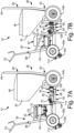
- FIG. 7A is a side elevation view of first spray module 12.
- FIG. 7B is a side elevation view of second spray module 12'.
- FIGS. 7A and 7B will be discussed together.
- Each of spray module 12 and spray module 12' include hopper module 26.
- Hopper module 26 includes hopper 30, lid 48, hopper frame 50, coupling 52, and wheels 54a-54c (wheel 54a is shown in FIGS. 2-4 ).
- Hopper frame 50 includes horizontal portion 56 and vertical portion 58.
- Vertical portion 58 includes hopper module handle 64.
- Horizontal portion 56 includes fixed frame portion 60 and movable frame portion 62.
- One fixed frame arm 106 of fixed frame portion 60 is shown.
- One movable frame arm 108 and frame end 110 of movable frame portion 62 is show.
- Movable frame arm 108 includes shoe 114.
- Spray module 12 further includes power module 28 ( FIG. 7A ).
- Power module 28 includes drive 32, pump 34, power frame 66, wheels 68a, 68b (wheel 68a shown in FIGS. 2-4 ), and control module 24.
- Drive housing 70 of drive 32 is shown.
- Cylinder 90 and pump outlet 72 of pump 34 are shown.
- Power frame 66 includes power module handle 74 and brackets 76.
- Spray module 12' further includes power module 28' ( FIG. 7B ).
- Power module 28' includes drive 32', pump 34', power frame 66', wheels 68a, 68b (wheel 68a shown in FIGS. 2-4 ), and control module 24.
- Drive housing 70' of drive 32' is shown.
- Cylinder 90' and pump outlet 72' of pump 34' are shown.
- Power frame 66' includes power module handle 74' and brackets 76'.
- Hopper 30 is disposed on and supported by hopper frame 50, and specifically by fixed frame portion 60 of hopper frame 50.
- Movable frame portion 62 extends from and is supported by fixed frame portion 60.
- Movable frame portion 62 supports power modules 28, 28'.
- Horizontal portion 56 extends from wheels 54a, 54b to wheel 54c (e.g., from the front wheels 54a, 54b to the back wheel 54c).
- Horizontal portion 56 is disposed horizontally with respect to the ground surface.
- no part of the power modules 28, 28', including wheels 68a, 68b touch the ground. Rather, the whole of power module 28, 28' is supported by wheels 54a-54c of hopper module 26.
- wheels 54a-54c of hopper module 26 support the full spray module 12, 12', including both hopper module 26 and power module 28, 28'.
- Spray modules 12, 12' provide significant advantages.
- a single hopper module 26 can accommodate multiple ones of power modules 28, 28'.
- Power modules 28, 28' can be dismounted from hopper module 26 and different power modules 28, 28' can be combined with different hopper modules 26.
- flexibility is built into the interface to allow for variation in types.
- different pumps 34, 34' may be configured for different applications, such as high pressure or high flow applications, or high aggregate or low aggregate materials.
- pumps 34, 34' have different lengths. The different lengths of pumps 34, 34' are accommodated by the modular nature of hopper frame 50.
- Movable frame portion 62 can be repositioned relative to fixed frame portion 60 to alter the size of the gap between motor housing 70, 70' and hopper 30, thereby allowing one hopper module 26 to accommodate multiple power modules 28, 28' having pumps 34, 34' of varying lengths.
- Spray module 12 further includes power module 28.
- Power module 28 includes drive 32, pump 34, power frame 66, wheels 68a, 68b, and control module 24.
- Drive housing 70 of drive 32 is shown.
- Cylinder 90 and pump outlet 72 of pump 34 are shown.
- Brackets 76 and feet 120 (only one foot 120 of feet 120 is shown) of power frame 66 are shown.
- Spray module 12' further includes power module 28'.
- Power module 28' includes drive 32', pump 34', power frame 66', wheels 68a, 68b, and control module 24.
- Drive housing 70' of drive 32' is shown.
- Cylinder 90' and pump outlet 72' of pump 34' are shown.
- Brackets 76' and feet 120 (only one foot 120 of feet 120 is shown) of power frame 66' are shown.
- Movable frame arms 108 are configured to engage fixed frame arms 106 and are movable relative to fixed frame arms 106 to adjust a length of horizontal portion 56.
- Movable frame arms 108 include movable arm holes 112 (visible in FIG. 8A ) that are arrayed along the length of movable frame arms 108.
- Movable arm holes 112 are configured to receive frame connector 102 extending through fixed frame portion 60 and movable frame portion 62 to fix the position of movable frame portion 62 relative to fixed frame portion 60.
- frame connector 102 can be a pin that extends through movable arm holes 112 in movable frame arm 108 and corresponding holes in fixed frame arm 106.
- Frame connector 102 prevents relative movement of movable frame portion 62 relative to fixed frame portion 60.
- Frame connector 102 can be removed from fixed frame portion 60 and movable frame portion 62 to allow relative movement between movable frame portion 62 and fixed frame portion 60 such that the length of horizontal portion 56 can be adjusted to facilitate mounting of different power modules 28, 28' on hopper module 26.
- Movable arm holes 112 can be spaced along movable frame portion 62 to align with holes through fixed frame arms 106 at relative positions corresponding to different lengths of horizontal portion 56.
- the different lengths of horizontal portion 56 provide the appropriate spacing to accommodate pumps 34, 34' of different lengths and ensure that pump inlets 100 (best seen in FIG. 3 ) of the pumps 34, 34' are properly aligned with hopper 30 to mount to hopper 30.
- Power module 28 including pump 34 having a first, longer length is shown in FIG. 8A .
- Power module 28' including pump 34' having a second, shorter length is shown in FIG. 8B .
- the user can adjust the length of horizontal portion 56 of hopper module 26 such that hopper module 26 can support and interface with power modules 28, 28' having pumps 34, 34' of different lengths.
- the user can swap out power modules 28, 28' having pumps 34, 34' of different lengths and displacements for different applications, such as high pressure or high flow applications, or high aggregate or low aggregate materials.
- the user wheels power module 28 into alignment with hopper module 26.
- the user can pull movable frame portion 62 away from fixed frame portion 60 to lengthen horizontal portion 56 of hopper frame 50 based on the length of pump 34.
- Frame connectors 102 are inserted through holes in fixed frame arms 106 and movable arm holes 112 in movable frame arms 108 secure movable frame portion 62 to fixed frame portion 60, thereby fixing the length of horizontal portion 56.
- Clamps 104 can be rotated to further secure movable frame portion 62 to fixed frame portion 60.
- the user pushes power module 28' onto movable frame portion 62 until feet 120 are disposed in and engage shoes 114. Tie 78 is tightened to secure power module 28' on hopper module 26. With feet 120 engaging shoes 114, the pump inlet of pump 34' engages hopper 30, forming the fluid connection between pump 34' and hopper 30. The user secures coupling 52 to pump 34', thereby making the mechanical connection between pump 34' and hopper 30. Spray module 12' is thus ready to spray.
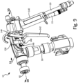
- FIG. 9 is a perspective view of spray gun 14.
- Spray gun 14 includes nozzle 40, gun body 138, handle 140, trigger 36, pivot 144, and detent mechanism 146. Button 148 of detent mechanism 146 is shown.
- Gun body 138 encloses various components of spray gun 14.
- Gun body 138 can be formed from metal, such as aluminum.
- Handle 140 projects from gun body 138.
- handle 140 is integrally formed with gun body 138 such that handle 140 and gun body 138 form a unitary part. It is understood, however, that handle 140 can be formed separate from gun body 138 and attached to gun body 138.
- Handle 140 is configured to be gripped by one hand of the user while that same gripping hand actuates trigger 36.
- Trigger 36 is mounted to gun body 138 at pivot 144. Actuating trigger 36 causes trigger 36 to rotate about pivot 144 to cause spraying by spray gun 14.
- Nozzle 40 is disposed at a spray outlet of spray gun 14 and is configured to eject material as a material spray.
- Detent mechanism 146 is at least partially disposed within gun body 138.
- button 148 projects out of a lateral side of gun body 138.
- Detent mechanism 146 can be actuated by the user, such as by pushing button 148, to perform a release action that will be further discussed herein.
- button 148 is exposed on the exterior of gun body 138.
- button 148 is exposed on only one lateral side (left or right side) of gun body 138.
- detent mechanism 146 can include buttons or other components exposed on both lateral sides and/or on one or both of the top and bottom sides of gun body 138. Button 148 projecting from gun body 138 provides the user with easy access for actuating detent mechanism 146.
- Spray hose 18 extends to gun body 138 and is configured to provide material to spray gun 14 for spraying by spray gun 14.
- Spray hose 18 receives material under pressure output by a pump, such as pump 34 (shown in FIGS. 1-7A and 8A ) and pump 34' (shown in FIGS. 7B and 8B ).
- Air hose 20 and signal line 22 extend to handle 140 and are mounted to handle 140. Air hose 20 supplies compressed air to spray gun 14 for generating the material spray. Air hose 20 receives the compressed air from a compressed air source, such as compressed air source 16 ( FIGS. 1 and 2 ). The compressed air hose 20 attaches to the bottom of handle 140.
- signal line 22 includes a cord having an inner conductor for conveying a control signal from spray gun 14 to control module 24 (best seen in FIG. 1 ). Each of spray hose 18, air hose 20, and signal line 22 can be disconnected from spray gun 14.
- Spray gun 14 is configured to receive material from spray hose 18 and compressed air from air hose 20.
- the material and compressed air mix within gun body 138 and are ejected as a material spray through nozzle 40.
- the flows of material and compressed air into and through gun body 138 are respectively controlled by material flow valve 160 and air flow valve 162.
- Trigger 36 is pivotably mounted to gun body 138 at pivot 144. Actuation of trigger 36 controls actuation of material flow valve 160 and air flow valve 162.
- Needle 168 is at least partially disposed in gun body 138. Needle 168 is an elongated component, such as a rod. A first end of needle 168 includes valve head 178. Valve head 178 can be formed as part of needle 168, or valve head 178 can be separate from and attached to and therefore move with needle 168. Valve head 178 is configured to interface with material valve seat 172 to seal and block material from flowing along material pathway 150 to mix chamber 154 and out of nozzle 40. Material valve spring 170 interfaces with needle 168 and is configured to bias needle 168 towards the closed position shown in FIG. 10A .
- Neck 174 is formed on a portion of needle 168 disposed outside of gun body 138. Trigger 36 engages neck 174.
- Air pathway 156 extends through gun body 138 from air inlet 158 to mix chamber 154.
- Air flow valve 162 is mounted to gun body 138. Air flow valve 162 is configured to control the flow of air from air inlet 158 to mix chamber 154. As such, air flow valve 162 regulates the flow of compressed air through air pathway 156 to mix chamber 154. Closure of air flow valve 162 blocks the flow of air, while opening of air flow valve 162 permits the flow of air. Opening and closing of air flow valve 162 is based on the state of actuation of trigger 36.
- Trigger 36 does not automatically fully release from the detent state and instead catches at a position between the non-actuated state and the actuated state.
- trigger 36 In the detent state, trigger 36 is not fully actuated but material flow valve 160 is open, insomuch that valve head 178 does not engage material valve seat 172 thereby allowing material from material inlet 152 to continue to flow through material pathway 150 through material flow valve 160 and into mix chamber 154 and out nozzle 40.
- Detent mechanism 146 stops forward movement of trigger 36 at a point where back side 142 of trigger 36 is still engaged with pin 180. Trigger 36 maintains pin 180 in such a position that that valve member 184 is disengaged from air valve seat 186.
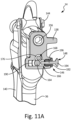
- detent mechanism 146 To exit the detent state, the user actuates detent mechanism 146 from the engaged state ( FIG. 11A ) to a release state ( FIG. 11B ). Actuating detent mechanism 146 is done by a different mechanical action than releasing trigger 36. With detent mechanism 146 in the release state, needle 168 and trigger 36 can move forward, as pushed by material valve spring 170, until valve head 178 engages material valve seat 172. Valve head 178 engaging material valve seat 172 closes material flow valve 160 thereby preventing material from passing through material flow valve 160 and stopping further spraying of material. With trigger 36 moving forward, pin 180 can likewise move forward to close air flow valve 162. Air valve spring 182 pushes pin 180 forward to engage valve member 184 with air valve seat 186, thereby closing air flow valve 162 and stopping further compressed air flow through air flow valve 162.
- first transducer component 188a When trigger 36 is shifted to the detent position, first transducer component 188a is far enough away from second transducer component 188b that second transducer component 188b no longer generates the signal indicating proximity of first transducer component 188a. With trigger 36 in the detent state, the second transducer component 188b does not send a signal indicative of the proximity of the first transducer component 188a or otherwise sends a signal indicating that trigger 36 is not in the actuated state. As such, control circuitry 42 deactivates or other reduces power to drive 32 such that drive 32 does not power pump 34.
- Stopping motor 86, and thereby pump 34, from operating when trigger 36 is in the detent state can help avoid a packout condition from occurring in spray gun 14.
- a packout condition occurs when the aggregate within the spray material collects at bottlenecks, valves, ridges, or other flow obstructions through the material pathway 150 or otherwise within the gun body 138. The collection of some aggregate can lead to further collection of other aggregate, thereby creating an obstruction. Further flow of the material can sometimes break up the collection of aggregate, however a deadhead condition, where pump 34 is running but spray gun 14 is not spraying, can compact and entrench the collection of aggregate. Deadhead conditions occur when pressure builds within the material pathway due to the downstream blockage. Such downstream blockage is typically caused by closure of material flow valve 160.
- first transducer component 188a When trigger 36 is in the detent position, first transducer component 188a is far enough away from second transducer component 188b that second transducer component 188b does not send a signal causing control circuitry 42 to power motor 86. Therefore, with trigger 36 in the detent position, motor 86 is deactivated. Also while trigger 36 is in the detent position, material flow valve 160 is maintained in an open position, allowing material in spray hose 18 and in material pathway 150 to flow downstream past material flow valve 160 and into mix chamber 154. As motor 86 has been deactivated and is no longer running, pump 34 will stop pumping within a short amount of time, such as one or two seconds, from when trigger 36 first enters the detent position.
- Actuating detent mechanism 146 includes a different motion than releasing trigger 36. Therefore, to fully return material flow valve 160 to the closed position associated with the trigger 36 non-actuated state from the open position associated with the trigger 36 actuated state, the user must first release trigger 36, which causes trigger 36 and needle 168 to move into the detent position ( FIG. 10C ) from the actuated position. Both material flow valve 160 and air flow valve 162 ( FIGS. 10A-10C ) are open with trigger 36 in the detent state. The user then actuates button 148 to cause ball 164 to disengage from groove 176. Ball 164 disengaging from groove 176 allows trigger 36 and needle 168 to move into the non-actuated state ( FIG. 10A ), which closes both material flow valve 160 and air flow valve 162.
- trigger 36 is further pulled through an angular distance and reaches position P5 at which a sensor, such as sensor 38 ( FIGS. 1 and 10A-10C ) (e.g., first and second transducer components 188a, 188b ( FIGS. 10A-10C )) generates and sends the activation signal to control circuitry 42 ( FIG. 1 ) to activate a driving mechanism, such as drive 32 (best seen in FIGS. 2 and 3 ) and cause motor 86 ( FIGS. 3 and 6 ) to turn on and/or power a pump, such as pump 34 ( FIGS. 1-7A and 8A ).
- a sensor such as sensor 38 ( FIGS. 1 and 10A-10C ) (e.g., first and second transducer components 188a, 188b ( FIGS. 10A-10C )) generates and sends the activation signal to control circuitry 42 ( FIG. 1 ) to activate a driving mechanism, such as drive 32 (best seen in FIGS. 2 and 3 ) and cause motor 86
- trigger 36 can further be pulled through an angular distance until trigger 36 reaches a fully actuated position P6, in which case air flow, material flow, and motor 86 are all engaged to spray material.
- the user can maintain trigger in the fully actuated position P6 to spray material on the surface.
- Outer ring portion 218 includes lower ring surface 222 and upper ring surface 224.
- Guides 220 includes legs 226 and arms 228. Each leg 226 includes upper outer angled surface 230, lower outer angled surface 232, and inner guide surface 234. Each arm 228 includes inner stop surface 236.
- Piston 94 is disposed within and configured to reciprocate within cylinder 90.
- Inlet housing 92 is mounted to cylinder 90.
- Inlet check valve 96 is contained within inlet housing 92.
- Piston check valve 98 is disposed within piston 94 such that piston check valve 98 reciprocates with piston 94.
- Channel 198 is generally circular/cylindrical, although the inner diameter of channel 198 changes along channel direction CD.
- Inlet housing 92 is symmetric about longitudinal pump axis P-P, such that each structural feature of inlet housing 92 shown can be understood to be circular about longitudinal pump axis P-P. It is understood, however, that the diameter of channel 198 and/or inlet housing 92 can change along the longitudinal pump axis P-P ( e.g., generally widening in the channel direction CD).
- Check seat 204 of inlet check valve 96 is supported by inlet housing 92.
- Check seat 204 can be a ring, among other shapes.
- Check seat 204 can be formed from ceramic, metal, or other materials.
- Check ball 206 is disposed in channel 198 and can be formed from ceramic, metal, rubber, or other materials.
- Check ball 206 is configured to annularly engage check seat 204 to prevent retrograde material flow (i.e. upstream, in a direction opposite channel direction CD).
- Ball return 208 is disposed on a downstream side of check ball 206.
- Return spring 214 is secured between ball guide 212 and cylinder 90.
- Return member 216 engages return spring 214, and return spring 214is configured to bias return member 216 in the upstream direction.
- Ring 210 is disposed within inlet housing 92 along channel 198. Ring 210 rests within, and against, the inner surface of inlet housing 92. As shown, ring 210 contacts check seat 204 and ball guide 212. Ring 210 can be formed from metal and/or rubber, among other options. In particular, ring 210 can include an outer ring portion formed from metal on which an inner ring portion, facing check ball 206, formed of rubber is molded. As such, ring 210 can be formed from multiple materials. The inner surface of ring 210 defines angled ring surface 211, which widens in the channel direction CD. As such, an upstream end of ring 210 can have a first diameter smaller than a second diameter of a downstream end of ring 210.
- the portion of channel 198 downstream from ring 210 is defined by angled channel surface 200, which can be formed by a portion of inlet housing 92. As shown, angled channel surface 200 widens downstream along channel direction CD. The portion of channel 198 downstream from angled channel surface 200 forms ledge 202. Ledge 202 is formed by a portion of inlet housing 92. Ball guide 212 is supported by inlet housing 92 and rests on ledge 202. More specifically, lower ring surface 222 of outer ring portion 218 of ball guide 212 rests on the surface of inlet housing 92 that defines ledge 202.
- Ball guide 212 is fully contained within inlet housing 92. Upper ring surface 224 of outer ring portion 218 of ball guide 212 is retained in inlet housing 92 by cylinder 90. In the example shown, upper ring surface 224 engages return spring 214 of ball return 208 while ball return 208 is further braced downstream by the upstream end of cylinder 90. Ball guide 212 sits within and extends along channel 198. Ball guide 212 is configured to limit movement of check ball 206 in channel direction CD and laterally relative to channel direction CD. In particular, ball guide 212 includes three inwardly projecting guides 220 to guide check ball 206 and limit travel of check ball 206.
- Each guide 220 includes leg 226 on an upstream side of outer ring portion 218 and arm 228 on the downstream side of outer ring portion 218. Each guide 220 limits the downstream travel of check ball 206 via arm 228 and lateral movement of check ball 206 via leg 226.
- Upper outer angled surfaces 230 of legs 226 interface with angled channel surface 200 of inlet housing 92. As such, upper outer angled surfaces 230 of legs 226 fit against, and are complementary to, angled channel surface 200.
- Lower outer angled surfaces 232 of legs 226 interface with angled ring surface 211 of ring 210. As such, lower outer angled surface 232 of legs 226 fit against, and are complementary to, angled ring surface 211.
- pump 34 may not include a ring 210. Instead, an angled surface similar to angled ring surface 211 can be formed by inlet housing 92. In such an example, lower outer angled surface 232 can be configured to fit against and along such angled surface formed by inlet housing 92.
- Inner guide surfaces 234 of legs 226 face check ball 206 and limit lateral movement of check ball 206.
- Arms 228 extend towards longitudinal pump axis P-P and inner stop surfaces 236 of arms 228 face check ball 206.
- Inner stop surfaces 236 are configured to engage check ball 206 to limit downstream travel of check ball 206.
- Inlet check valve 96 provides significant advantages. Inlet check valve 96, including the shape of inlet housing 92 and of ball guide 212, assists in avoiding packout conditions. Packout conditions can occur when aggregate material in the fluid is allowed to accumulate on surfaces, typically flat surfaces. Therefore, many of the surfaces along channel 198 are angled relative to longitudinal pump axis P-P, minimizing exposed flat surfaces. Ring 210 includes angled ring surface 211 to inhibit accumulation of aggregate material on ring 210. Angled channel surface 200 of inlet housing 92 is likewise angled relative to longitudinal pump axis P-P to inhibit aggregate accumulation on inlet housing 92. As further shown herein, inwardly projecting guides 220 include several features that inhibit accumulation of aggregate material either on ball guide 212 itself or on other surfaces along channel 198.
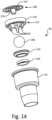
- FIG. 14 is an exploded view of inlet check valve 96.
- Inlet housing 92 of pump 34 (best seen in FIG. 13A ) is shown.
- Inlet check valve 96 includes check seat 204, check ball 206, ball return 208, ring 210, and ball guide 212.
- Ball return 208 includes return spring 214 and return member 216. Legs 226 and outer ring portion 218 of ball guide 212 are shown.
- ball return 208 includes return member 216 surrounded by return spring 214.
- Return spring 214 is a metallic coil.
- Ball guide 212 includes three legs 226 extending downward from outer ring portion 218 of ball guide 212. While three legs 226 are shown, a greater or lesser number of legs 226 can be provided as part of ball guide 212, such as two or four legs 226, for example.
- ring 210 and check seat 204 are annular.
- Check ball 206 is disposed between check seat 204 and ball guide 212.
- FIG. 15A is a top isometric view of ball guide 212.
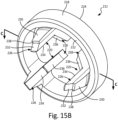
- FIG. 15B is a bottom isometric view of ball guide 212.
- FIG. 15C is a cross-sectional view of ball guide 212 taken along line C-C in FIG. 15B .
- FIGS. 15A-15C will be discussed together.
- Ball guide 212 includes outer ring portion 218 and guides 220.
- Outer ring portion 218 includes lower ring surface 222 and upper ring surface 224.
- Guides 220 includes legs 226 and arms 228. Each leg 226 includes upper outer angled surface 230, lower outer angled surface 232, inner guide surface 234, and corner 238.
- Each arm 228 includes inner stop surface 236.
- Outer ring portion 218 is annular and arms 228 and legs 226 extend from outer ring portion 218. Arms 228 extend above outer ring portion 218. Legs 226 extend below outer ring portion 218. Other than the connection to outer ring portion 218, legs 226 and arms 228 are not supported by any other ring or cylindrical structure. Each of arms 228 and legs 226 project outward (e.g. at least partially along longitudinal pump axis P-P ( FIG. 13A )) from outer ring portion 218 such that each of arms 228 and legs 226 have free ends that do not contact or connect with any other portions of ball guide 212.
- arms 228 extend inward from outer ring portion 218 towards the pump axis P-P and do not connect with one another (except indirectly by being attached to the same outer ring portion 218).
- legs 226 extend inward from outer ring portion 218 towards the pump axis P-P and do not connect with one another (except indirectly by being attached to the same outer ring portion 218).
- Inner guide surfaces 234 are inward facing and extend along legs 226. Inner guide surfaces 234 are configured to guide check ball 206 (best seen in FIG. 13B ) as check ball 206 moves up and down during pumping, preventing check ball 206 from moving laterally offset from longitudinal pump axis P-P, which would otherwise inhibit reseating of check ball 206 on check seat 204 (best seen in FIG. 13B ). Inner guide surfaces 234 extend parallel along longitudinal pump axis P-P. Lower outer angled surfaces 232 of legs 226 are disposed on a laterally opposite side of legs 226 from inner guide surface 234. Lower outer angled surfaces 232 fit against and along angled ring surface 211 ( FIG. 13B ).
- lower outer angled surfaces 232 have the same pitch as angled ring surface 211 so that the surfaces extend parallel with each other to facilitate engagement. In some examples, there is no space between lower outer angled surface 232 and angled ring surface 211 (or a substitute angled surface such as a channel surface of the inlet housing 92) so that aggregate and other debris cannot be caught between the surfaces.
- Each leg 226 further includes upper outer angled surface 230.
- Upper outer angled surface 230 is configured to fit against and along angled channel surface 200 ( FIG. 13B ).
- upper outer angled surface 230 has the same pitch as angled channel surface 200 so that upper outer angled surface 230 and angled channel surface 200 extend parallel with each other.
- arms 228 and legs 226 have some thickness to them in the circumferential direction and are not merely wires. Corner 238 transitions between different pitches of lower outer angled surface 232 and the upper outer angled surface 230.
- Arms 228 each include inner stop surface 236.
- Inner stop surfaces 236 are configured to engage check ball 206 to prevent further upward, downstream movement of check ball 206 along longitudinal pump axis P-P. Such inner stop surfaces 236 prevent check ball 206 from moving too far away from check seat 204 during pumping such that check ball 206 can quickly move into place on check seat 204 when piston 94 (best seen in FIG. 13A ) transitions from the upward suction stroke to the downward pumping stroke.
- Inner stop surface 236, as with arm 228, is angled relative to longitudinal pump axis P-P. Arms 228 extend above upper ring surface 224 of outer ring portion 218.
- inner stop surface 236 extends above upper ring surface 224 of outer ring portion 218 such that a portion of check ball 206 can extend beyond (i.e. above) outer ring portion 218. If outer ring portion 218 was moved upward relative to arms 228 such that arms 228 did not extend above outer ring portion 218, then outer ring portion 218 would either have to be longer, which increases a surface area of outer ring portion 218 and risks aggregate accumulation, and/or legs 226 would have to be longer, which increases the difficulty of manufacturing and reduces the strength of legs 226. As such, arms 228 extending above outer ring portion 218 facilitates a compact and balanced structure of ball guide 212.
- FIG. 16A is a first side elevation view of ball guide 212.
- FIG. 16B is a second side elevation view of ball guide 212.
- FIG. 16C is a top elevation view of ball guide 212.
- FIG. 16D is a third side elevation view of ball guide 212.
- FIG. 16E is a bottom elevation view of ball guide 212.
- Ball guide 212 includes outer ring portion 218 and guides 220.
- Outer ring portion 218 includes lower ring surface 222 and upper ring surface 224.
- Guides 220 includes legs 226 and arms 228. As shown in FIGS. 16A-16E , guides 220 are evenly arrayed about the inner circumference of outer ring portion 218.
Landscapes
- Engineering & Computer Science (AREA)
- Mechanical Engineering (AREA)
- General Engineering & Computer Science (AREA)
- Road Paving Machines (AREA)
- Nozzles (AREA)
- Reciprocating Pumps (AREA)
- Filling, Topping-Up Batteries (AREA)
Applications Claiming Priority (3)
| Application Number | Priority Date | Filing Date | Title |
|---|---|---|---|
| US201962797047P | 2019-01-25 | 2019-01-25 | |
| US201962814939P | 2019-03-07 | 2019-03-07 | |
| US16/560,328 US11440038B2 (en) | 2019-01-25 | 2019-09-04 | Material sprayer |
Publications (2)
| Publication Number | Publication Date |
|---|---|
| EP3685922A1 EP3685922A1 (en) | 2020-07-29 |
| EP3685922B1 true EP3685922B1 (en) | 2023-12-20 |
Family
ID=68387216
Family Applications (1)
| Application Number | Title | Priority Date | Filing Date |
|---|---|---|---|
| EP19205823.8A Active EP3685922B1 (en) | 2019-01-25 | 2019-10-29 | Material sprayer |
Country Status (4)
| Country | Link |
|---|---|
| US (1) | US11440038B2 (pl) |
| EP (1) | EP3685922B1 (pl) |
| CN (3) | CN115532461A (pl) |
| PL (1) | PL3685922T3 (pl) |
Families Citing this family (11)
| Publication number | Priority date | Publication date | Assignee | Title |
|---|---|---|---|---|
| US11440038B2 (en) * | 2019-01-25 | 2022-09-13 | Graco Minnesota Inc. | Material sprayer |
| US11406995B2 (en) | 2019-01-25 | 2022-08-09 | Graco Minnesota Inc. | Material spray gun |
| CN110453890B (zh) * | 2019-07-26 | 2025-03-11 | 江苏万象建工集团有限公司 | 一种外墙真石漆喷涂设备 |
| USD958294S1 (en) * | 2020-01-09 | 2022-07-19 | Zhejiang Prulde Electric Appliance Co., Ltd. | Spray gun |
| US12172176B2 (en) | 2020-10-01 | 2024-12-24 | Graco Minnesota Inc. | Battery powered fluid sprayer |
| CN113146679B (zh) * | 2021-04-20 | 2022-06-03 | 哈尔滨工业大学 | 一种不完全约束快速对接机构 |
| US12097524B2 (en) | 2021-07-20 | 2024-09-24 | Graco Minnesota Inc. | Fluid sprayer with covered battery |
| CN114541705B (zh) * | 2022-03-17 | 2023-12-12 | 中建八局第三建设有限公司 | 一种大型群体住宅高效建造中防渗漏装置及施工方法 |
| CN115680243B (zh) * | 2022-11-10 | 2025-04-08 | 陈�峰 | 一种混凝土建筑墙体可校准平整涂覆机构及方法 |
| CN119926083B (zh) * | 2025-04-08 | 2025-07-01 | 山西省水利建筑工程局集团有限公司 | 一种土方开挖的降尘装置及其降尘方法 |
| CN120006922B (zh) * | 2025-04-22 | 2025-07-11 | 山西六建集团有限公司 | 一种外墙装饰用喷涂装置 |
Family Cites Families (44)
| Publication number | Priority date | Publication date | Assignee | Title |
|---|---|---|---|---|
| US2789756A (en) | 1954-07-28 | 1957-04-23 | Harry J Allen | Convertible power unit |
| US2820672A (en) * | 1956-07-17 | 1958-01-21 | Lee Mart Mfg Co | Apparatus for controllably applying semifluid and pasty materials |
| US3780953A (en) | 1972-01-21 | 1973-12-25 | J Malec | Airless spray gun |
| US3844487A (en) | 1972-01-21 | 1974-10-29 | J Malec | Airless spray gun |
| US3841555A (en) | 1972-08-14 | 1974-10-15 | D Lilja | Spray apparatus and method |
| US3893621A (en) | 1974-01-24 | 1975-07-08 | Jay Johnson | Plastic spray gun |
| US4166579A (en) | 1976-09-07 | 1979-09-04 | Stewart-Warner Corporation | Paint sprayer safety interlock |
| US4925101A (en) | 1988-08-26 | 1990-05-15 | Nordson Corporation | Wax spray gun and nozzle |
| US5156340A (en) | 1991-01-23 | 1992-10-20 | Lopes Gregory A | Fluid spray gun |
| US5228842A (en) * | 1991-07-30 | 1993-07-20 | Wagner Spray Tech Corporation | Quick-change fluid section for piston-type paint pumps |
| CN2112454U (zh) | 1992-02-26 | 1992-08-12 | 河北省廊坊市防水建筑材料厂 | 焦油聚氨酯喷涂机 |
| US5263789A (en) | 1992-03-03 | 1993-11-23 | Wagner Spray Tech Corporation | Line striper accessory |
| US5318314A (en) * | 1992-09-29 | 1994-06-07 | Wagner Spray Tech Corporation | Paint hopper assembly |
| US5441297A (en) | 1993-11-10 | 1995-08-15 | Graco Inc. | Power unit cart |
| US5570839A (en) | 1994-01-31 | 1996-11-05 | Glas-Craft, Inc. | Plural component flow monitoring system |
| US5538402A (en) | 1994-08-31 | 1996-07-23 | Mckenney; Joseph E. | Modular spraying apparatus |
| US5618001A (en) | 1995-03-20 | 1997-04-08 | Binks Manufacturing Company | Spray gun for aggregates |
| US5718534A (en) | 1996-03-13 | 1998-02-17 | Fine Line Plastics Corp. | Rear drive ride-on tractor unit for propelling steerable utility vehicles such as walk-behind paint stripers |
| US5803313A (en) | 1996-05-21 | 1998-09-08 | Illinois Tool Works Inc. | Hand held fluid dispensing apparatus |
| US6484782B1 (en) | 1999-09-29 | 2002-11-26 | Mudmaster, L.L.C. | Grout applicator system |
| GB2382119B (en) | 2001-11-16 | 2005-05-18 | Calder Ltd | A high pressure water control device |
| US6415958B1 (en) | 2002-01-07 | 2002-07-09 | Illinois Tool Works, Inc. | Needle valve actuator for hot melt adhesive hand applicator and a method for operating the same |
| US7114664B2 (en) * | 2004-04-15 | 2006-10-03 | Graco Minnesota Inc. | Texture sprayer with removable engine-compressor module |
| US7604246B2 (en) | 2005-06-23 | 2009-10-20 | Briggs And Stratton Corporation | Frame for an vertical shaft engine-driven assembly |
| US8167170B2 (en) | 2006-06-15 | 2012-05-01 | Handy & Harman | Adhesive dispenser system |
| US7926740B2 (en) | 2007-04-04 | 2011-04-19 | Black & Decker Inc. | Pressure washer system and operating method |
| US8113795B1 (en) | 2007-11-06 | 2012-02-14 | David Vanell | System with coupling mechanisms |
| US20110079321A1 (en) * | 2008-05-08 | 2011-04-07 | Mattson Barry W | Texture hopper |
| US20100014908A1 (en) | 2008-07-18 | 2010-01-21 | Campbell Shawn O | Joint compound tool |
| KR101017387B1 (ko) | 2009-01-14 | 2011-02-28 | 도요 고무 고교 가부시키가이샤 | 프로스법 경질 폴리우레탄폼의 제조 장치 |
| US8651397B2 (en) | 2009-03-09 | 2014-02-18 | Techtronic Power Tools Technology Limited | Paint sprayer |
| CN201558765U (zh) | 2009-12-09 | 2010-08-25 | 浙江奥利达气动工具股份有限公司 | 多功能喷漆枪 |
| US20140264126A1 (en) | 2013-03-13 | 2014-09-18 | Gssc, Inc. | Reduced Wear Valve |
| US20150060579A1 (en) | 2013-08-29 | 2015-03-05 | Finishing Brands Holdings Inc. | Electrostatic Spray System |
| US9457824B2 (en) | 2014-01-14 | 2016-10-04 | Black Cat, Inc. | Mobile cart for spray dispensing |
| US9352763B2 (en) | 2014-01-14 | 2016-05-31 | Black Cat, Inc. | Mobile cart for spray dispensing |
| US9700905B2 (en) | 2014-01-14 | 2017-07-11 | Black Cat, Inc. | Mobile cart for spray dispensing |
| CN104437924B (zh) | 2014-12-05 | 2017-08-25 | 湖南三民重工科技有限公司 | 移动式耐火材料无级调节流量压力搅拌一体喷涂系统 |
| US10758933B2 (en) | 2016-03-01 | 2020-09-01 | Carlisle Fluid Technologies, Inc. | Fluid regulation system |
| CN205926087U (zh) | 2016-06-17 | 2017-02-08 | 佛山市联智新创科技有限公司 | 一种彩色涂料的喷涂设备 |
| DE102016009957A1 (de) | 2016-08-19 | 2018-02-22 | Sata Gmbh & Co. Kg | Spritzpistole mit Abzugssperre, Abzugssperre für eine Spritzpistole und Verfahren zum Anbringen, zum Aktivieren und zum Deaktivieren einer Abzugssperre |
| US11724272B2 (en) | 2016-10-26 | 2023-08-15 | Carlisle Fluid Technologies, Inc. | Systems and methods for a material sensor for a material pump |
| CN106890739A (zh) | 2017-02-28 | 2017-06-27 | 台州市精德机电科技有限公司 | 一种具有调压功能的喷雾机 |
| US11440038B2 (en) * | 2019-01-25 | 2022-09-13 | Graco Minnesota Inc. | Material sprayer |
-
2019
- 2019-09-04 US US16/560,328 patent/US11440038B2/en active Active
- 2019-10-29 PL PL19205823.8T patent/PL3685922T3/pl unknown
- 2019-10-29 EP EP19205823.8A patent/EP3685922B1/en active Active
- 2019-11-18 CN CN202211303710.2A patent/CN115532461A/zh active Pending
- 2019-11-18 CN CN201921997037.0U patent/CN211801729U/zh active Active
- 2019-11-18 CN CN201911127050.5A patent/CN111482293B/zh active Active
Also Published As
| Publication number | Publication date |
|---|---|
| US11440038B2 (en) | 2022-09-13 |
| CN211801729U (zh) | 2020-10-30 |
| CN111482293A (zh) | 2020-08-04 |
| EP3685922A1 (en) | 2020-07-29 |
| US20200238318A1 (en) | 2020-07-30 |
| CN115532461A (zh) | 2022-12-30 |
| PL3685922T3 (pl) | 2024-04-22 |
| CN111482293B (zh) | 2022-11-11 |
Similar Documents
| Publication | Publication Date | Title |
|---|---|---|
| EP3685923B1 (en) | Material spray gun | |
| US11440038B2 (en) | Material sprayer | |
| US20140306028A1 (en) | Drywall spraying assembly | |
| US12172180B2 (en) | Fluid sprayer | |
| CN104043549B (zh) | 便携式无空气喷雾器 | |
| US5203839A (en) | Apparatus for dispensing adhesive materials | |
| US12228117B2 (en) | Pump control system and method | |
| CN101829640A (zh) | 喷漆器 | |
| CN112368082B (zh) | 用于油漆和其他涂料的手持式无气喷涂器 | |
| CN211801751U (zh) | 泵 | |
| US20030138569A1 (en) | Wall board compound dispenser with catalyst mixer | |
| US5879456A (en) | Tube coating system | |
| JPH0791363A (ja) | 搬送ポンプ | |
| CN121909079A (zh) | 多组分分配装置 | |
| WO2007042434A1 (en) | Portable gap filling machine |
Legal Events
| Date | Code | Title | Description |
|---|---|---|---|
| PUAI | Public reference made under article 153(3) epc to a published international application that has entered the european phase |
Free format text: ORIGINAL CODE: 0009012 |
|
| STAA | Information on the status of an ep patent application or granted ep patent |
Free format text: STATUS: THE APPLICATION HAS BEEN PUBLISHED |
|
| AK | Designated contracting states |
Kind code of ref document: A1 Designated state(s): AL AT BE BG CH CY CZ DE DK EE ES FI FR GB GR HR HU IE IS IT LI LT LU LV MC MK MT NL NO PL PT RO RS SE SI SK SM TR |
|
| AX | Request for extension of the european patent |
Extension state: BA ME |
|
| STAA | Information on the status of an ep patent application or granted ep patent |
Free format text: STATUS: REQUEST FOR EXAMINATION WAS MADE |
|
| 17P | Request for examination filed |
Effective date: 20210105 |
|
| RBV | Designated contracting states (corrected) |
Designated state(s): AL AT BE BG CH CY CZ DE DK EE ES FI FR GB GR HR HU IE IS IT LI LT LU LV MC MK MT NL NO PL PT RO RS SE SI SK SM TR |
|
| STAA | Information on the status of an ep patent application or granted ep patent |
Free format text: STATUS: EXAMINATION IS IN PROGRESS |
|
| 17Q | First examination report despatched |
Effective date: 20210607 |
|
| GRAP | Despatch of communication of intention to grant a patent |
Free format text: ORIGINAL CODE: EPIDOSNIGR1 |
|
| STAA | Information on the status of an ep patent application or granted ep patent |
Free format text: STATUS: GRANT OF PATENT IS INTENDED |
|
| INTG | Intention to grant announced |
Effective date: 20230717 |
|
| GRAS | Grant fee paid |
Free format text: ORIGINAL CODE: EPIDOSNIGR3 |
|
| P01 | Opt-out of the competence of the unified patent court (upc) registered |
Effective date: 20231002 |
|
| GRAA | (expected) grant |
Free format text: ORIGINAL CODE: 0009210 |
|
| STAA | Information on the status of an ep patent application or granted ep patent |
Free format text: STATUS: THE PATENT HAS BEEN GRANTED |
|
| AK | Designated contracting states |
Kind code of ref document: B1 Designated state(s): AL AT BE BG CH CY CZ DE DK EE ES FI FR GB GR HR HU IE IS IT LI LT LU LV MC MK MT NL NO PL PT RO RS SE SI SK SM TR |
|
| REG | Reference to a national code |
Ref country code: GB Ref legal event code: FG4D |
|
| REG | Reference to a national code |
Ref country code: DE Ref legal event code: R096 Ref document number: 602019043514 Country of ref document: DE |
|
| REG | Reference to a national code |
Ref country code: CH Ref legal event code: EP |
|
| REG | Reference to a national code |
Ref country code: IE Ref legal event code: FG4D |
|
| REG | Reference to a national code |
Ref country code: NL Ref legal event code: FP |
|
| PG25 | Lapsed in a contracting state [announced via postgrant information from national office to epo] |
Ref country code: GR Free format text: LAPSE BECAUSE OF FAILURE TO SUBMIT A TRANSLATION OF THE DESCRIPTION OR TO PAY THE FEE WITHIN THE PRESCRIBED TIME-LIMIT Effective date: 20240321 |
|
| REG | Reference to a national code |
Ref country code: LT Ref legal event code: MG9D |
|
| PG25 | Lapsed in a contracting state [announced via postgrant information from national office to epo] |
Ref country code: LT Free format text: LAPSE BECAUSE OF FAILURE TO SUBMIT A TRANSLATION OF THE DESCRIPTION OR TO PAY THE FEE WITHIN THE PRESCRIBED TIME-LIMIT Effective date: 20231220 |
|
| PG25 | Lapsed in a contracting state [announced via postgrant information from national office to epo] |
Ref country code: ES Free format text: LAPSE BECAUSE OF FAILURE TO SUBMIT A TRANSLATION OF THE DESCRIPTION OR TO PAY THE FEE WITHIN THE PRESCRIBED TIME-LIMIT Effective date: 20231220 |
|
| PG25 | Lapsed in a contracting state [announced via postgrant information from national office to epo] |
Ref country code: LT Free format text: LAPSE BECAUSE OF FAILURE TO SUBMIT A TRANSLATION OF THE DESCRIPTION OR TO PAY THE FEE WITHIN THE PRESCRIBED TIME-LIMIT Effective date: 20231220 Ref country code: GR Free format text: LAPSE BECAUSE OF FAILURE TO SUBMIT A TRANSLATION OF THE DESCRIPTION OR TO PAY THE FEE WITHIN THE PRESCRIBED TIME-LIMIT Effective date: 20240321 Ref country code: FI Free format text: LAPSE BECAUSE OF FAILURE TO SUBMIT A TRANSLATION OF THE DESCRIPTION OR TO PAY THE FEE WITHIN THE PRESCRIBED TIME-LIMIT Effective date: 20231220 Ref country code: ES Free format text: LAPSE BECAUSE OF FAILURE TO SUBMIT A TRANSLATION OF THE DESCRIPTION OR TO PAY THE FEE WITHIN THE PRESCRIBED TIME-LIMIT Effective date: 20231220 Ref country code: BG Free format text: LAPSE BECAUSE OF FAILURE TO SUBMIT A TRANSLATION OF THE DESCRIPTION OR TO PAY THE FEE WITHIN THE PRESCRIBED TIME-LIMIT Effective date: 20240320 |
|
| REG | Reference to a national code |
Ref country code: AT Ref legal event code: MK05 Ref document number: 1642041 Country of ref document: AT Kind code of ref document: T Effective date: 20231220 |
|
| PG25 | Lapsed in a contracting state [announced via postgrant information from national office to epo] |
Ref country code: SE Free format text: LAPSE BECAUSE OF FAILURE TO SUBMIT A TRANSLATION OF THE DESCRIPTION OR TO PAY THE FEE WITHIN THE PRESCRIBED TIME-LIMIT Effective date: 20231220 Ref country code: RS Free format text: LAPSE BECAUSE OF FAILURE TO SUBMIT A TRANSLATION OF THE DESCRIPTION OR TO PAY THE FEE WITHIN THE PRESCRIBED TIME-LIMIT Effective date: 20231220 Ref country code: NO Free format text: LAPSE BECAUSE OF FAILURE TO SUBMIT A TRANSLATION OF THE DESCRIPTION OR TO PAY THE FEE WITHIN THE PRESCRIBED TIME-LIMIT Effective date: 20240320 Ref country code: LV Free format text: LAPSE BECAUSE OF FAILURE TO SUBMIT A TRANSLATION OF THE DESCRIPTION OR TO PAY THE FEE WITHIN THE PRESCRIBED TIME-LIMIT Effective date: 20231220 Ref country code: HR Free format text: LAPSE BECAUSE OF FAILURE TO SUBMIT A TRANSLATION OF THE DESCRIPTION OR TO PAY THE FEE WITHIN THE PRESCRIBED TIME-LIMIT Effective date: 20231220 |
|
| PG25 | Lapsed in a contracting state [announced via postgrant information from national office to epo] |
Ref country code: IS Free format text: LAPSE BECAUSE OF FAILURE TO SUBMIT A TRANSLATION OF THE DESCRIPTION OR TO PAY THE FEE WITHIN THE PRESCRIBED TIME-LIMIT Effective date: 20240420 |
|
| PG25 | Lapsed in a contracting state [announced via postgrant information from national office to epo] |
Ref country code: CZ Free format text: LAPSE BECAUSE OF FAILURE TO SUBMIT A TRANSLATION OF THE DESCRIPTION OR TO PAY THE FEE WITHIN THE PRESCRIBED TIME-LIMIT Effective date: 20231220 Ref country code: AT Free format text: LAPSE BECAUSE OF FAILURE TO SUBMIT A TRANSLATION OF THE DESCRIPTION OR TO PAY THE FEE WITHIN THE PRESCRIBED TIME-LIMIT Effective date: 20231220 |
|
| PG25 | Lapsed in a contracting state [announced via postgrant information from national office to epo] |
Ref country code: SK Free format text: LAPSE BECAUSE OF FAILURE TO SUBMIT A TRANSLATION OF THE DESCRIPTION OR TO PAY THE FEE WITHIN THE PRESCRIBED TIME-LIMIT Effective date: 20231220 |
|
| PG25 | Lapsed in a contracting state [announced via postgrant information from national office to epo] |
Ref country code: SM Free format text: LAPSE BECAUSE OF FAILURE TO SUBMIT A TRANSLATION OF THE DESCRIPTION OR TO PAY THE FEE WITHIN THE PRESCRIBED TIME-LIMIT Effective date: 20231220 Ref country code: SK Free format text: LAPSE BECAUSE OF FAILURE TO SUBMIT A TRANSLATION OF THE DESCRIPTION OR TO PAY THE FEE WITHIN THE PRESCRIBED TIME-LIMIT Effective date: 20231220 Ref country code: RO Free format text: LAPSE BECAUSE OF FAILURE TO SUBMIT A TRANSLATION OF THE DESCRIPTION OR TO PAY THE FEE WITHIN THE PRESCRIBED TIME-LIMIT Effective date: 20231220 Ref country code: IT Free format text: LAPSE BECAUSE OF FAILURE TO SUBMIT A TRANSLATION OF THE DESCRIPTION OR TO PAY THE FEE WITHIN THE PRESCRIBED TIME-LIMIT Effective date: 20231220 Ref country code: IS Free format text: LAPSE BECAUSE OF FAILURE TO SUBMIT A TRANSLATION OF THE DESCRIPTION OR TO PAY THE FEE WITHIN THE PRESCRIBED TIME-LIMIT Effective date: 20240420 Ref country code: EE Free format text: LAPSE BECAUSE OF FAILURE TO SUBMIT A TRANSLATION OF THE DESCRIPTION OR TO PAY THE FEE WITHIN THE PRESCRIBED TIME-LIMIT Effective date: 20231220 Ref country code: CZ Free format text: LAPSE BECAUSE OF FAILURE TO SUBMIT A TRANSLATION OF THE DESCRIPTION OR TO PAY THE FEE WITHIN THE PRESCRIBED TIME-LIMIT Effective date: 20231220 Ref country code: AT Free format text: LAPSE BECAUSE OF FAILURE TO SUBMIT A TRANSLATION OF THE DESCRIPTION OR TO PAY THE FEE WITHIN THE PRESCRIBED TIME-LIMIT Effective date: 20231220 |
|
| PG25 | Lapsed in a contracting state [announced via postgrant information from national office to epo] |
Ref country code: PT Free format text: LAPSE BECAUSE OF FAILURE TO SUBMIT A TRANSLATION OF THE DESCRIPTION OR TO PAY THE FEE WITHIN THE PRESCRIBED TIME-LIMIT Effective date: 20240422 |
|
| PG25 | Lapsed in a contracting state [announced via postgrant information from national office to epo] |
Ref country code: PT Free format text: LAPSE BECAUSE OF FAILURE TO SUBMIT A TRANSLATION OF THE DESCRIPTION OR TO PAY THE FEE WITHIN THE PRESCRIBED TIME-LIMIT Effective date: 20240422 |
|
| REG | Reference to a national code |
Ref country code: DE Ref legal event code: R097 Ref document number: 602019043514 Country of ref document: DE |
|
| PG25 | Lapsed in a contracting state [announced via postgrant information from national office to epo] |
Ref country code: DK Free format text: LAPSE BECAUSE OF FAILURE TO SUBMIT A TRANSLATION OF THE DESCRIPTION OR TO PAY THE FEE WITHIN THE PRESCRIBED TIME-LIMIT Effective date: 20231220 |
|
| PLBE | No opposition filed within time limit |
Free format text: ORIGINAL CODE: 0009261 |
|
| STAA | Information on the status of an ep patent application or granted ep patent |
Free format text: STATUS: NO OPPOSITION FILED WITHIN TIME LIMIT |
|
| PG25 | Lapsed in a contracting state [announced via postgrant information from national office to epo] |
Ref country code: SI Free format text: LAPSE BECAUSE OF FAILURE TO SUBMIT A TRANSLATION OF THE DESCRIPTION OR TO PAY THE FEE WITHIN THE PRESCRIBED TIME-LIMIT Effective date: 20231220 |
|
| PG25 | Lapsed in a contracting state [announced via postgrant information from national office to epo] |
Ref country code: SI Free format text: LAPSE BECAUSE OF FAILURE TO SUBMIT A TRANSLATION OF THE DESCRIPTION OR TO PAY THE FEE WITHIN THE PRESCRIBED TIME-LIMIT Effective date: 20231220 Ref country code: DK Free format text: LAPSE BECAUSE OF FAILURE TO SUBMIT A TRANSLATION OF THE DESCRIPTION OR TO PAY THE FEE WITHIN THE PRESCRIBED TIME-LIMIT Effective date: 20231220 |
|
| 26N | No opposition filed |
Effective date: 20240923 |
|
| REG | Reference to a national code |
Ref country code: CH Ref legal event code: PL |
|
| PG25 | Lapsed in a contracting state [announced via postgrant information from national office to epo] |
Ref country code: MC Free format text: LAPSE BECAUSE OF FAILURE TO SUBMIT A TRANSLATION OF THE DESCRIPTION OR TO PAY THE FEE WITHIN THE PRESCRIBED TIME-LIMIT Effective date: 20231220 |
|
| PG25 | Lapsed in a contracting state [announced via postgrant information from national office to epo] |
Ref country code: BE Free format text: LAPSE BECAUSE OF NON-PAYMENT OF DUE FEES Effective date: 20241031 Ref country code: LU Free format text: LAPSE BECAUSE OF NON-PAYMENT OF DUE FEES Effective date: 20241029 |
|
| PG25 | Lapsed in a contracting state [announced via postgrant information from national office to epo] |
Ref country code: CH Free format text: LAPSE BECAUSE OF NON-PAYMENT OF DUE FEES Effective date: 20241031 |
|
| REG | Reference to a national code |
Ref country code: BE Ref legal event code: MM Effective date: 20241031 |
|
| PG25 | Lapsed in a contracting state [announced via postgrant information from national office to epo] |
Ref country code: IE Free format text: LAPSE BECAUSE OF NON-PAYMENT OF DUE FEES Effective date: 20241029 |
|
| PGFP | Annual fee paid to national office [announced via postgrant information from national office to epo] |
Ref country code: NL Payment date: 20251026 Year of fee payment: 7 |
|
| PGFP | Annual fee paid to national office [announced via postgrant information from national office to epo] |
Ref country code: DE Payment date: 20251029 Year of fee payment: 7 |
|
| PGFP | Annual fee paid to national office [announced via postgrant information from national office to epo] |
Ref country code: GB Payment date: 20251027 Year of fee payment: 7 |
|
| PGFP | Annual fee paid to national office [announced via postgrant information from national office to epo] |
Ref country code: FR Payment date: 20251027 Year of fee payment: 7 |
|
| PGFP | Annual fee paid to national office [announced via postgrant information from national office to epo] |
Ref country code: PL Payment date: 20251003 Year of fee payment: 7 |
|
| PG25 | Lapsed in a contracting state [announced via postgrant information from national office to epo] |
Ref country code: HU Free format text: LAPSE BECAUSE OF FAILURE TO SUBMIT A TRANSLATION OF THE DESCRIPTION OR TO PAY THE FEE WITHIN THE PRESCRIBED TIME-LIMIT; INVALID AB INITIO Effective date: 20191029 |
|
| PG25 | Lapsed in a contracting state [announced via postgrant information from national office to epo] |
Ref country code: CY Free format text: LAPSE BECAUSE OF FAILURE TO SUBMIT A TRANSLATION OF THE DESCRIPTION OR TO PAY THE FEE WITHIN THE PRESCRIBED TIME-LIMIT; INVALID AB INITIO Effective date: 20191029 |