EP3685899B1 - Suction tube filter arrangement and fluid tank system for a fluid tank - Google Patents
Suction tube filter arrangement and fluid tank system for a fluid tank Download PDFInfo
- Publication number
- EP3685899B1 EP3685899B1 EP19305089.5A EP19305089A EP3685899B1 EP 3685899 B1 EP3685899 B1 EP 3685899B1 EP 19305089 A EP19305089 A EP 19305089A EP 3685899 B1 EP3685899 B1 EP 3685899B1
- Authority
- EP
- European Patent Office
- Prior art keywords
- suction tube
- filter member
- arrangement
- fluid tank
- filter
- Prior art date
- Legal status (The legal status is an assumption and is not a legal conclusion. Google has not performed a legal analysis and makes no representation as to the accuracy of the status listed.)
- Active
Links
Images


Classifications
-
- B—PERFORMING OPERATIONS; TRANSPORTING
- B01—PHYSICAL OR CHEMICAL PROCESSES OR APPARATUS IN GENERAL
- B01D—SEPARATION
- B01D35/00—Filtering devices having features not specifically covered by groups B01D24/00 - B01D33/00, or for applications not specifically covered by groups B01D24/00 - B01D33/00; Auxiliary devices for filtration; Filter housing constructions
- B01D35/02—Filters adapted for location in special places, e.g. pipe-lines, pumps, stop-cocks
- B01D35/027—Filters adapted for location in special places, e.g. pipe-lines, pumps, stop-cocks rigidly mounted in or on tanks or reservoirs
-
- B—PERFORMING OPERATIONS; TRANSPORTING
- B01—PHYSICAL OR CHEMICAL PROCESSES OR APPARATUS IN GENERAL
- B01D—SEPARATION
- B01D29/00—Filters with filtering elements stationary during filtration, e.g. pressure or suction filters, not covered by groups B01D24/00 - B01D27/00; Filtering elements therefor
- B01D29/11—Filters with filtering elements stationary during filtration, e.g. pressure or suction filters, not covered by groups B01D24/00 - B01D27/00; Filtering elements therefor with bag, cage, hose, tube, sleeve or like filtering elements
-
- F—MECHANICAL ENGINEERING; LIGHTING; HEATING; WEAPONS; BLASTING
- F01—MACHINES OR ENGINES IN GENERAL; ENGINE PLANTS IN GENERAL; STEAM ENGINES
- F01N—GAS-FLOW SILENCERS OR EXHAUST APPARATUS FOR MACHINES OR ENGINES IN GENERAL; GAS-FLOW SILENCERS OR EXHAUST APPARATUS FOR INTERNAL-COMBUSTION ENGINES
- F01N3/00—Exhaust or silencing apparatus having means for purifying, rendering innocuous, or otherwise treating exhaust
- F01N3/08—Exhaust or silencing apparatus having means for purifying, rendering innocuous, or otherwise treating exhaust for rendering innocuous
- F01N3/10—Exhaust or silencing apparatus having means for purifying, rendering innocuous, or otherwise treating exhaust for rendering innocuous by thermal or catalytic conversion of noxious components of exhaust
- F01N3/18—Exhaust or silencing apparatus having means for purifying, rendering innocuous, or otherwise treating exhaust for rendering innocuous by thermal or catalytic conversion of noxious components of exhaust characterised by methods of operation; Control
- F01N3/20—Exhaust or silencing apparatus having means for purifying, rendering innocuous, or otherwise treating exhaust for rendering innocuous by thermal or catalytic conversion of noxious components of exhaust characterised by methods of operation; Control specially adapted for catalytic conversion
- F01N3/206—Adding periodically or continuously substances to exhaust gases for promoting purification, e.g. catalytic material in liquid form, NOx reducing agents
- F01N3/2066—Selective catalytic reduction [SCR]
-
- B—PERFORMING OPERATIONS; TRANSPORTING
- B01—PHYSICAL OR CHEMICAL PROCESSES OR APPARATUS IN GENERAL
- B01D—SEPARATION
- B01D29/00—Filters with filtering elements stationary during filtration, e.g. pressure or suction filters, not covered by groups B01D24/00 - B01D27/00; Filtering elements therefor
- B01D29/60—Filters with filtering elements stationary during filtration, e.g. pressure or suction filters, not covered by groups B01D24/00 - B01D27/00; Filtering elements therefor integrally combined with devices for controlling the filtration
-
- B—PERFORMING OPERATIONS; TRANSPORTING
- B01—PHYSICAL OR CHEMICAL PROCESSES OR APPARATUS IN GENERAL
- B01D—SEPARATION
- B01D29/00—Filters with filtering elements stationary during filtration, e.g. pressure or suction filters, not covered by groups B01D24/00 - B01D27/00; Filtering elements therefor
- B01D29/60—Filters with filtering elements stationary during filtration, e.g. pressure or suction filters, not covered by groups B01D24/00 - B01D27/00; Filtering elements therefor integrally combined with devices for controlling the filtration
- B01D29/601—Filters with filtering elements stationary during filtration, e.g. pressure or suction filters, not covered by groups B01D24/00 - B01D27/00; Filtering elements therefor integrally combined with devices for controlling the filtration by clearness or turbidity measuring
-
- B—PERFORMING OPERATIONS; TRANSPORTING
- B01—PHYSICAL OR CHEMICAL PROCESSES OR APPARATUS IN GENERAL
- B01D—SEPARATION
- B01D29/00—Filters with filtering elements stationary during filtration, e.g. pressure or suction filters, not covered by groups B01D24/00 - B01D27/00; Filtering elements therefor
- B01D29/60—Filters with filtering elements stationary during filtration, e.g. pressure or suction filters, not covered by groups B01D24/00 - B01D27/00; Filtering elements therefor integrally combined with devices for controlling the filtration
- B01D29/605—Filters with filtering elements stationary during filtration, e.g. pressure or suction filters, not covered by groups B01D24/00 - B01D27/00; Filtering elements therefor integrally combined with devices for controlling the filtration by level measuring
-
- B—PERFORMING OPERATIONS; TRANSPORTING
- B01—PHYSICAL OR CHEMICAL PROCESSES OR APPARATUS IN GENERAL
- B01D—SEPARATION
- B01D35/00—Filtering devices having features not specifically covered by groups B01D24/00 - B01D33/00, or for applications not specifically covered by groups B01D24/00 - B01D33/00; Auxiliary devices for filtration; Filter housing constructions
- B01D35/02—Filters adapted for location in special places, e.g. pipe-lines, pumps, stop-cocks
-
- B—PERFORMING OPERATIONS; TRANSPORTING
- B01—PHYSICAL OR CHEMICAL PROCESSES OR APPARATUS IN GENERAL
- B01D—SEPARATION
- B01D35/00—Filtering devices having features not specifically covered by groups B01D24/00 - B01D33/00, or for applications not specifically covered by groups B01D24/00 - B01D33/00; Auxiliary devices for filtration; Filter housing constructions
- B01D35/02—Filters adapted for location in special places, e.g. pipe-lines, pumps, stop-cocks
- B01D35/027—Filters adapted for location in special places, e.g. pipe-lines, pumps, stop-cocks rigidly mounted in or on tanks or reservoirs
- B01D35/0276—Filtering elements with a vertical rotation or symmetry axis mounted on tanks or reservoirs
-
- B—PERFORMING OPERATIONS; TRANSPORTING
- B01—PHYSICAL OR CHEMICAL PROCESSES OR APPARATUS IN GENERAL
- B01D—SEPARATION
- B01D35/00—Filtering devices having features not specifically covered by groups B01D24/00 - B01D33/00, or for applications not specifically covered by groups B01D24/00 - B01D33/00; Auxiliary devices for filtration; Filter housing constructions
- B01D35/18—Heating or cooling the filters
-
- B—PERFORMING OPERATIONS; TRANSPORTING
- B01—PHYSICAL OR CHEMICAL PROCESSES OR APPARATUS IN GENERAL
- B01D—SEPARATION
- B01D36/00—Filter circuits or combinations of filters with other separating devices
- B01D36/001—Filters in combination with devices for the removal of gas, air purge systems
-
- B—PERFORMING OPERATIONS; TRANSPORTING
- B01—PHYSICAL OR CHEMICAL PROCESSES OR APPARATUS IN GENERAL
- B01D—SEPARATION
- B01D39/00—Filtering material for liquid or gaseous fluids
- B01D39/08—Filter cloth, i.e. woven, knitted or interlaced material
-
- B—PERFORMING OPERATIONS; TRANSPORTING
- B01—PHYSICAL OR CHEMICAL PROCESSES OR APPARATUS IN GENERAL
- B01D—SEPARATION
- B01D53/00—Separation of gases or vapours; Recovering vapours of volatile solvents from gases; Chemical or biological purification of waste gases, e.g. engine exhaust gases, smoke, fumes, flue gases, aerosols
- B01D53/34—Chemical or biological purification of waste gases
- B01D53/38—Removing components of undefined structure
-
- B—PERFORMING OPERATIONS; TRANSPORTING
- B01—PHYSICAL OR CHEMICAL PROCESSES OR APPARATUS IN GENERAL
- B01D—SEPARATION
- B01D53/00—Separation of gases or vapours; Recovering vapours of volatile solvents from gases; Chemical or biological purification of waste gases, e.g. engine exhaust gases, smoke, fumes, flue gases, aerosols
- B01D53/34—Chemical or biological purification of waste gases
- B01D53/92—Chemical or biological purification of waste gases of engine exhaust gases
-
- B—PERFORMING OPERATIONS; TRANSPORTING
- B01—PHYSICAL OR CHEMICAL PROCESSES OR APPARATUS IN GENERAL
- B01D—SEPARATION
- B01D2201/00—Details relating to filtering apparatus
- B01D2201/20—Pressure-related systems for filters
- B01D2201/204—Systems for applying vacuum to filters
-
- B—PERFORMING OPERATIONS; TRANSPORTING
- B01—PHYSICAL OR CHEMICAL PROCESSES OR APPARATUS IN GENERAL
- B01D—SEPARATION
- B01D2251/00—Reactants
- B01D2251/20—Reductants
- B01D2251/206—Ammonium compounds
- B01D2251/2067—Urea
-
- B—PERFORMING OPERATIONS; TRANSPORTING
- B01—PHYSICAL OR CHEMICAL PROCESSES OR APPARATUS IN GENERAL
- B01D—SEPARATION
- B01D2258/00—Sources of waste gases
- B01D2258/01—Engine exhaust gases
-
- F—MECHANICAL ENGINEERING; LIGHTING; HEATING; WEAPONS; BLASTING
- F01—MACHINES OR ENGINES IN GENERAL; ENGINE PLANTS IN GENERAL; STEAM ENGINES
- F01N—GAS-FLOW SILENCERS OR EXHAUST APPARATUS FOR MACHINES OR ENGINES IN GENERAL; GAS-FLOW SILENCERS OR EXHAUST APPARATUS FOR INTERNAL-COMBUSTION ENGINES
- F01N2240/00—Combination or association of two or more different exhaust treating devices, or of at least one such device with an auxiliary device, not covered by indexing codes F01N2230/00 or F01N2250/00, one of the devices being
- F01N2240/16—Combination or association of two or more different exhaust treating devices, or of at least one such device with an auxiliary device, not covered by indexing codes F01N2230/00 or F01N2250/00, one of the devices being an electric heater, i.e. a resistance heater
-
- F—MECHANICAL ENGINEERING; LIGHTING; HEATING; WEAPONS; BLASTING
- F01—MACHINES OR ENGINES IN GENERAL; ENGINE PLANTS IN GENERAL; STEAM ENGINES
- F01N—GAS-FLOW SILENCERS OR EXHAUST APPARATUS FOR MACHINES OR ENGINES IN GENERAL; GAS-FLOW SILENCERS OR EXHAUST APPARATUS FOR INTERNAL-COMBUSTION ENGINES
- F01N2260/00—Exhaust treating devices having provisions not otherwise provided for
- F01N2260/26—Exhaust treating devices having provisions not otherwise provided for for preventing enter of dirt into the device
-
- F—MECHANICAL ENGINEERING; LIGHTING; HEATING; WEAPONS; BLASTING
- F01—MACHINES OR ENGINES IN GENERAL; ENGINE PLANTS IN GENERAL; STEAM ENGINES
- F01N—GAS-FLOW SILENCERS OR EXHAUST APPARATUS FOR MACHINES OR ENGINES IN GENERAL; GAS-FLOW SILENCERS OR EXHAUST APPARATUS FOR INTERNAL-COMBUSTION ENGINES
- F01N2560/00—Exhaust systems with means for detecting or measuring exhaust gas components or characteristics
- F01N2560/12—Other sensor principles, e.g. using electro conductivity of substrate or radio frequency
-
- F—MECHANICAL ENGINEERING; LIGHTING; HEATING; WEAPONS; BLASTING
- F01—MACHINES OR ENGINES IN GENERAL; ENGINE PLANTS IN GENERAL; STEAM ENGINES
- F01N—GAS-FLOW SILENCERS OR EXHAUST APPARATUS FOR MACHINES OR ENGINES IN GENERAL; GAS-FLOW SILENCERS OR EXHAUST APPARATUS FOR INTERNAL-COMBUSTION ENGINES
- F01N2610/00—Adding substances to exhaust gases
- F01N2610/02—Adding substances to exhaust gases the substance being ammonia or urea
-
- F—MECHANICAL ENGINEERING; LIGHTING; HEATING; WEAPONS; BLASTING
- F01—MACHINES OR ENGINES IN GENERAL; ENGINE PLANTS IN GENERAL; STEAM ENGINES
- F01N—GAS-FLOW SILENCERS OR EXHAUST APPARATUS FOR MACHINES OR ENGINES IN GENERAL; GAS-FLOW SILENCERS OR EXHAUST APPARATUS FOR INTERNAL-COMBUSTION ENGINES
- F01N2610/00—Adding substances to exhaust gases
- F01N2610/10—Adding substances to exhaust gases the substance being heated, e.g. by heating tank or supply line of the added substance
-
- F—MECHANICAL ENGINEERING; LIGHTING; HEATING; WEAPONS; BLASTING
- F01—MACHINES OR ENGINES IN GENERAL; ENGINE PLANTS IN GENERAL; STEAM ENGINES
- F01N—GAS-FLOW SILENCERS OR EXHAUST APPARATUS FOR MACHINES OR ENGINES IN GENERAL; GAS-FLOW SILENCERS OR EXHAUST APPARATUS FOR INTERNAL-COMBUSTION ENGINES
- F01N2610/00—Adding substances to exhaust gases
- F01N2610/14—Arrangements for the supply of substances, e.g. conduits
- F01N2610/1406—Storage means for substances, e.g. tanks or reservoirs
-
- F—MECHANICAL ENGINEERING; LIGHTING; HEATING; WEAPONS; BLASTING
- F01—MACHINES OR ENGINES IN GENERAL; ENGINE PLANTS IN GENERAL; STEAM ENGINES
- F01N—GAS-FLOW SILENCERS OR EXHAUST APPARATUS FOR MACHINES OR ENGINES IN GENERAL; GAS-FLOW SILENCERS OR EXHAUST APPARATUS FOR INTERNAL-COMBUSTION ENGINES
- F01N2610/00—Adding substances to exhaust gases
- F01N2610/14—Arrangements for the supply of substances, e.g. conduits
- F01N2610/1426—Filtration means
-
- F—MECHANICAL ENGINEERING; LIGHTING; HEATING; WEAPONS; BLASTING
- F01—MACHINES OR ENGINES IN GENERAL; ENGINE PLANTS IN GENERAL; STEAM ENGINES
- F01N—GAS-FLOW SILENCERS OR EXHAUST APPARATUS FOR MACHINES OR ENGINES IN GENERAL; GAS-FLOW SILENCERS OR EXHAUST APPARATUS FOR INTERNAL-COMBUSTION ENGINES
- F01N2610/00—Adding substances to exhaust gases
- F01N2610/14—Arrangements for the supply of substances, e.g. conduits
- F01N2610/1486—Means to prevent the substance from freezing
-
- Y—GENERAL TAGGING OF NEW TECHNOLOGICAL DEVELOPMENTS; GENERAL TAGGING OF CROSS-SECTIONAL TECHNOLOGIES SPANNING OVER SEVERAL SECTIONS OF THE IPC; TECHNICAL SUBJECTS COVERED BY FORMER USPC CROSS-REFERENCE ART COLLECTIONS [XRACs] AND DIGESTS
- Y02—TECHNOLOGIES OR APPLICATIONS FOR MITIGATION OR ADAPTATION AGAINST CLIMATE CHANGE
- Y02A—TECHNOLOGIES FOR ADAPTATION TO CLIMATE CHANGE
- Y02A50/00—TECHNOLOGIES FOR ADAPTATION TO CLIMATE CHANGE in human health protection, e.g. against extreme weather
- Y02A50/20—Air quality improvement or preservation, e.g. vehicle emission control or emission reduction by using catalytic converters
-
- Y—GENERAL TAGGING OF NEW TECHNOLOGICAL DEVELOPMENTS; GENERAL TAGGING OF CROSS-SECTIONAL TECHNOLOGIES SPANNING OVER SEVERAL SECTIONS OF THE IPC; TECHNICAL SUBJECTS COVERED BY FORMER USPC CROSS-REFERENCE ART COLLECTIONS [XRACs] AND DIGESTS
- Y02—TECHNOLOGIES OR APPLICATIONS FOR MITIGATION OR ADAPTATION AGAINST CLIMATE CHANGE
- Y02T—CLIMATE CHANGE MITIGATION TECHNOLOGIES RELATED TO TRANSPORTATION
- Y02T10/00—Road transport of goods or passengers
- Y02T10/10—Internal combustion engine [ICE] based vehicles
- Y02T10/12—Improving ICE efficiencies
Definitions
- the invention relates to a suction tube filter arrangement for a fluid tank, in particular for a tank containing urea solution.
- the invention further relates to a fluid tank system, in particular for a tank containing urea solution, wherein the fluid tank system comprises at least one heating coil and at least one suction tube filter arrangement.
- Suction tubes are used for the suction of fluid from a fluid tank.
- a suction tube may be provided with a filter member that allows only solution to enter the suction tube.
- a filter member is arranged at a lower end of the suction tube in order to protect an inlet opening of the suction tube.
- a sock-shaped bag filter for a urea solution tank is known.
- the bag filter surrounds a heating coil, a suction tube and a sensor rod.
- the bag filter is supported by support structures and the heating coil itself.
- the support structures and the heating coil extend circumferentially around the suction tube and are spaced apart from the same.
- a filter for a gasoline tank is known from US 4,411,788 A .
- the filter comprises a skeleton formed by a bottom plate, four support columns and an annular reinforcing frame. To the skeleton, a cylindrical net as filter member is attached in a manner that it is thereby spaced apart from the suction tube.
- a filter for an in-tank pump of an automobile fuel tank is known.
- the filter comprises an outer mesh member that is supported by a skeleton made from ribs. Inside the skeleton, a suction nozzle is arranged that comprises a mesh cylinder for fuel intake.
- a suction tube filter arrangement which comprises at least one suction tube that defines a suction tube direction, and at least one filter member, wherein the suction tube is at least partially arranged inside the filter member and the filter member extends along the suction tube direction, wherein the at least one suction tube forms a support structure for the at least one filter member, the filter member being expanded by the suction tube, and wherein the filter member without suction tube is a flat body that gets expanded by the suction tube, forming an overall lens-shaped cross section perpendicular to a longitudinal direction, the longitudinal direction being defined by the suction tube direction, wherein the at least one suction tube is provided with at least one monolithically integrated fixation means for undetachably fixating the filter member on the suction tube and with at least one connection port for connecting the arrangement with a counter connection port of a fluid tank system, and wherein the suction tube together with the at least one monolithically integrated fixation means and the at least one connection port is formed as a single piece from a
- the fluid tank system according to the invention is provided with a suction tube filter arrangement according to the invention, wherein said arrangement is arranged inside a space which is surrounded by the at least one heating coil.
- the suction tube is arranged inside a filter member that extends along the suction tube direction.
- the filter member extending along the suction may allow gas bubbles to ascend inside the filter member away from an inlet opening of the suction tube such that suction of gas bubbles may be prevented. Furthermore, a compact arrangement can be achieved.
- the fluid tank system may prevent frozen solution from blocking the suction tube. If frozen solution is present inside a fluid tank, the solution inside the space which is surrounded by the heating coil is generally heated up earlier than the solution outside said space. Consequently, frozen solution inside said space will melt earlier than the solution outside said space. Due to this arrangement, the solution can be pumped from the tank even when there is still frozen solution present in the tank.
- the invention is in particular intended to be used for tanks containing diesel exhaust fluid (DEF) for cleaning diesel exhaust emissions.
- the suction tube may be a part of a DEF-dosing system.
- the fluid tank system according to the invention may be such a DEF-dosing system or a part thereof.
- the suction tube filter arrangement according to the invention may also be used in fluid tank systems, in particular in DEF-dosing systems without a heating coil. This may for example be the case in regions where there is no risk of freezing the solution.
- the suction tube forms a support structure for the filter member.
- the at least one filter member is at least partially supported by the at least one suction tube.
- the filter member is expanded by the suction tube.
- the filter member may in particular, be expanded in a depth direction of the filter member.
- the suction tube and the filter member are both elongated along the suction tube direction.
- This elongated shape may increase the tendency of gas bubbles to ascend inside the filter member away from an inlet opening of the suction tube.
- the elongated shape of the filter member may provide a large surface which the solution may pass to the suction tube. Thereby, a flow rate of the solution may be increased.
- An inlet opening of the suction tube is preferably arranged inside the filter member.
- the suction tube and the filter member may form a unit that can easily be replaced in a fluid tank system.
- a length of the suction tube filter arrangement may be adjustable in order to meet different filter specifications.
- the length of the suction tube and/or the filter member may be chosen depending on the intended application.
- An inner volume may be opened up by an expanded filter member, wherein the at least one inner volume may extend between an outer wall of the suction tube and the filter member, said fluid volume extending along the suction tube direction and being in fluid communication with an inlet opening of the suction tube.
- the inner volume may extend in the vicinity of the inlet opening and also along a vertical direction upwards from said inlet opening. Thereby, gas bubbles may easily ascend away from the inlet opening.
- the filter member is a basically flat body that gets expanded by the suction tube, forming an overall lens-shaped cross section.
- the at least one suction tube is provided with at least one monolithically integrated fixation means for undetachably fixating the filter member on the suction tube.
- the at least one fixation means is preferably formed as a flange on the suction tube to which the at least one filter member is attachable. Due to the monolithically integrated fixation means, the number of parts of the arrangement may be reduced.
- the at least one suction tube is provided with at least one connection port for connecting the arrangement with a counter connection port of a fluid tank system.
- the connection port is formed monolithically with the suction tube.
- the at least one suction tube is made from a plastic material. Thereby, the costs may be reduced, in particular in comparison with a suction tube made from steel.
- the suction tube is provided with a fixation means and a connection port and all the elements are formed monolithically with the suction tube from plastic. Thereby, the suction tube together with the fixation means and the connection port are formed as a single piece.
- the at least one filter member is preferably made from fabric, in particular from woven fibers.
- An inlet port of the suction tube is preferably arranged at a bottom of the filter member.
- the upper part of the filter member may allow the solution to enter the filter member. The solution may then flow inside the filter member to its bottom and enter the inlet opening of the suction tube.
- the filter member and the suction tube according to the invention are preferably assembled to a unit that can be sold separately, in particular as a replacement part. Due to the suction tube filter arrangement comprising a suction tube, the system sided suction tube of a fluid tank system may have a reduced length. Since those system sided suction tubes are generally made from steel, the costs of the overall system may be reduced.
- a set of suction tube filter arrangements having different lengths can be provided. These suction tube filter arrangements may be interchangeable in order to meet different requirements of a fluid tank system.
- the fluid tank system according to the invention may further be improved in that an inlet port of the at least one suction tube is arranged inside the space which is surrounded by the at least one heating coil. Thereby, it can be achieved that only liquid solution enters the suction tube.
- the at least one filter member and preferably also the suction tube extend basically parallel to a gas-bubble ascension direction.
- Said gas-bubble ascension direction is parallel with a gravity direction.
- the fluid tank system preferably further comprises at least one counter connection port to which the suction tube filter arrangement can be undetachably connected.
- the counter connection port may be provided with at least one sealing ring, preferably an o-ring.
- Said sealing ring is preferably arranged on an outer side of a system sided suction tube that may form a part of the counter connection port. Said sealing ring may abut a connection port of the suction tube of the suction tube filter arrangement in order to form a gas tight connection.
- the fluid tank system may further comprise at least one jig for mounting a sealing ring on the system sided suction tube.
- the jig may be sold together with a suction tube filter arrangement or a fluid tank system according to the invention.
- the fluid tank system further comprises at least one fluid sensor arrangement, wherein the suction tube filter arrangement is arranged side-by-side to the at least one fluid sensor arrangement, in particular in a direction perpendicular to a gas-bubble ascension direction.
- the fluid sensor arrangement is preferably a quality sensor and/or a fluid level sensor.
- the side-by-side arrangement may provide a compact structure.
- an inlet port of the suction tube is arranged on a level with the at least one fluid sensor arrangement along a gas-bubble ascension direction. Due to this arrangement, the properties measured by the sensor arrangement reflect the properties of the solution that enters the suction tube.
- the at least one fluid sensor arrangement is preferably provided with a bottom plate that basically closes the space which is surrounded by the at least one heating coil, wherein the bottom plate is provided with at least one cutout for the at least one suction tube filter arrangement.
- suction tube filter arrangement 1 in the following denoted as "arrangement 1" is described with respect to Figs. 1 to 3 .
- a fluid tank system which is provided with the arrangement 1 will be described later on.
- the arrangement 1 comprises a suction tube 3 and a filter member 5.
- the suction tube 3 may be used for the suction of a solution from a tank (not shown).
- the filter member 5 may prevent debris and/or frozen solutions from entering the suction tube 3.
- Both the suction tube 3 and the filter member 5 have overall elongated shapes.
- the suction tube 3 defines a suction tube direction S.
- This suction tube direction S defines a longitudinal direction L of the arrangement 1.
- the filter member 5 extends along the suction tube direction S and thereby parallel with the longitudinal direction L of the arrangement.
- the longitudinal direction L of the arrangement 1 is preferably aligned parallel with a gas bubble ascension direction B that is parallel with the gravitational direction G but orientated in the opposing direction.
- the gas bubble ascension direction B is the direction along which gas bubbles may ascend from the solution in the tank.
- the suction tube 3 is basically arranged inside the filter member 5. In other words, the greater part of the suction tube 3 is arranged inside the filter member 5 such that it is surrounded by the filter member 5.
- the suction tube 3 comprises a suction end 7 and a connection end 9, wherein the ends 7 and 9 are arranged opposing each other along the suction tube direction S.
- the suction end 7 forms the lower end of the suction tube 3
- the connection end 9 forms the upper end of the suction tube 3.
- the suction tube 3 has an inlet opening 11 which opens the suction tube 3 to its surrounding and which allows a solution to enter the suction tube 3.
- the inlet opening 11 is arranged inside the filter member 5.
- An inner volume 13 extends inside the filter member 5 and is basically arranged between the suction tube 3 and the material of the filter member 5. Said inner volume 13 is in fluid communication with the inlet opening 11 of the suction tube 3. The inner volume 13 extends between the suction end 7 and the lower end 15 of the filter member 5. The lower end 15 is that end of the filter member 5 which is arranged along the longitudinal direction L closer to the suction end 7 than to the connection end 9 of the suction tube 3.
- the inner volume 13 further extends parallel to the longitudinal direction L through the filter member 5 adjacent to the suction tube 3.
- the inner volume 13 extends basically along the greater part of a length of the filter member 5 along the longitudinal direction L.
- most of the material 17 of the filter can be used by a solution to enter the inner volume 13 through the filter member 5 and reach the inlet opening 11 of the suction tube 3.
- the inner volume 13 which is indicated by the dashed line in Fig. 2 , is basically composed of two vertical strands 19 which longitudinally extend parallel to the longitudinal direction L, and a horizontal strand 21 which is closest to the inlet opening 11.
- the vertical strands 19 and the horizontal strand 21 basically form a U-shaped structured inner volume 13.
- the inlet opening 11 is arranged at the bottom 23 of the filter member 5, said bottom being located at the lower end 15 of the filter member 5.
- the inner volume 13 has the benefit that the bulk of the material 17 can be used for a solution to enter the filter member 5 and to flow through the inner volume 13 towards and into the inlet opening 11. Thereby, the effective area that is used for a solution to pass the filter member 5 is increased in comparison to a filter member that covers only the inlet opening 11.
- the vertical strands 19 may allow gas bubbles in the solution inside the inner volume 13 to ascend along the gas bubble ascension direction B along the vertical strands 19 and away from the inlet opening 11. Thereby, the suction of gas bubbles into the suction tube 3 may be prevented.
- the filter member 5 without the suction tube 3 may be an overall flat body.
- the material 17 of the filter member 5 is preferably a fabric 25, preferably a woven material. More preferably, the filter member 5 is made from a woven fiber structure.
- the suction tube 3 preferably serves as a support structure 27 for the filter member 5.
- the suction tube 3 may expand the material 17 of the filter member 5, thereby defining the structure of the filter member 5 and the outer shape of the arrangement 1.
- the filter member 5 may be expanded to an overall lens-shape. This shape can be seen in Fig. 3 . Thereby, two opposing sections 29 of the suction tube 3 abut the material 17 of the filter member 5, expanding the filter member 5 along a depth direction D.
- the filter member 5 Perpendicular to said depth direction D and the longitudinal direction L, the filter member 5 extends along a width direction W.
- the depth 33 is composed of an outer diameter 35 of the suction tube 3 and two times the material thickness 37 of the material 17. Due to the width 31 being larger than the depth D, the lateral strands 19 of the inner volume 13 are opened up inside the filter member 5.
- the filter member 5 comprises a seam 39. Said seam 39 joining at least two parts 41, 43 of the filter material 17 in order to form the filter member 5. Preferably the parts 41 and 43 are two halves of a single piece of fabric. The piece of fabric may be folded in order to form the filter member 5. The seam forms the margin of the filter member 5, at least at the lower end 15 and at the two sides which are opposed to each other along the width direction W.
- the filter member 5 could also be pre-shaped in order to receive the suction tube 3.
- the suction tube 3 could be provided with an additional support structure in order to define the shape of the filter member 5. Said additional support structure could in particular be monolithically formed with the suction tube 3.
- the filter member 5 could be provided with an inner support structure, for example made from plastic, said support structure expanding the filter member 5 to a required shape.
- the suction tube 3 preferably comprises at least one fixation means 45, to which the filter member 5 can be undetachably fixated.
- Said fixation means 45 is preferably formed monolithically with the remaining suction tube 3.
- the fixation means 45 is shaped as a flange 47. Said flange 47 may be provided with a circumferential groove 49 into which material 17 of the filter member 5 can be inserted to fixate the filter member 5 on the suction tube 3.
- the fixation means 45 is preferably arranged at the connection end 9 of the suction tube 3.
- the suction tube 3 is preferably further provided with at least one connection port 51.
- the connection port 51 can be used for connecting the arrangement 1 with a counter connection port of a fluid tank system.
- the connection port 51 is adapted for establishing a fluid communication between the suction tube 3 and further parts of a fluid tank system, in particular a fluid pump.
- the connection port 51 may further mechanically mount the arrangement 1 in the fluid tank system.
- the suction tube 3 is preferably made from plastic material. If the suction tube 3 is provided with a fixation means 45 for the filter member 5 and/or with a connection port 51, these features are preferably formed integrally with the remaining suction tube 3. In other words, the suction tube 3, the fixation means 45 and/or the connection port 51 are preferably monolithically formed from plastic.
- a fluid tank system 53 according to the invention is described with respect to Figs. 4 to 6 .
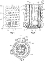
- Fig. 4 shows a side view of the system 53
- Fig. 5 shows a cut through the system 53 showing the interior of the same
- Fig. 6 shows a view of the system 53 from below the system 53.
- the fluid tank system 53 is provided with an arrangement 1 as described above with respect to Figs. 1 to 3 .
- the fluid tank system 53 may be arranged inside a fluid tank 55, in particular a fluid tank 55 for urea solution 57.
- the solution may be used for cleaning diesel exhaust fumes.
- a fluid tank 55 is only indicated by a dashed line in Fig. 4 .
- the fluid tank system 53 comprises a heating coil 59 and an arrangement 1 as described above.
- the heating coil 59 is intended to heat a solution 57 inside a tank 55 to a working temperature.
- the heating coil 59 may be used for melting a frozen solution 57.
- the heating coil 53 is preferably arranged in a helical structure 61, said helical structure 61 surrounding a space 63.
- the inlet opening 11 of the suction tube 3 is preferably also arranged inside the space 63.
- the filter member 5 and preferably also the suction tube 3 extend basically parallel to the gas bubble ascension direction B, as mentioned before.
- the system 53 is provided with a counter connection port 65.
- Said counter connection port 65 may be the end of a system-sided suction tube 67 which may be connected to a pump (not shown).
- the system-sided suction tube 67 is preferably made from steel.
- a sealing ring 69 may be present on an outside of the system-sided suction tube 67.
- the sealing ring 69 is arranged inside the connection port 51, thereby forming a gas-tight connection between the suction tube 3 and the system-sided suction tube 67.
- the fluid tank system 53 further comprises at least one fluid sensor arrangement 71.
- the fluid sensor arrangement 71 may be provided with a quality sensor and/or with a liquid level sensor.
- the fluid sensor arrangement 71 is preferably arranged at the lower end of a sensor tube 73 which mounts the sensor arrangement 71 and which provides an inner space 75 for power and/or data lines for the sensor arrangement 71.
- the suction tube filter arrangement 1 is arranged side-by-side to the fluid sensor arrangement 71.
- the properties measured by the sensor arrangement 71 reflect the properties of the solution 57 entering the filter member 5 and thereby the suction tube 3.
- the sensor arrangement 71 has a bottom plate 77 onto which sensor components are mounted.
- the bottom plate is preferably arranged at the lower side 79 of the system 53.
- the term "lower side” refers to the side of the system 53 that is aligned towards the gravitational direction G.
- the bottom plate 77 basically closes the space 63.
- the bottom plate 77 is preferably provided with a cutout 81 for the arrangement 1.
- the lower end 15 of the filter member 5 may be arranged in the cutout 81. Due to this arrangement, the inlet opening 11 may be basically on a level with the sensor arrangement 71 along the suction tube direction S.
- the fluid tank system 53 may comprise a jig 83 for mounting a sealing ring 69 on the system-sided suction tube 67.
- the jig 83 may be provided with an insertion portion 85 for insertion into the system-sided suction tube 67. By inserting the insertion portion 85 into the tube 67, the jig 83 is pre-aligned. During further insertion of the insertion portion 85, the tube 67 is guided into a receiving groove 87 of the jig 83 which circumferentially surrounds the insertion portion 85.
- the receiving groove 87 itself is circumferentially surrounded by a sealing ring holding ridge 89 onto which a sealing ring 69 may be placed.
- the sealing ring holding ridge 89 is bordered by a holding ring 91.
- the sealing ring 69 When the tube 67 enters the receiving groove 87, the sealing ring 69 is placed on the tube 67.
- the depth of the groove 87 may define the position of the sealing ring 69 on the tube 67 in the longitudinal direction of the tube 67.
- the tube 67 may be provided with a bulge 93 that extends circumferentially around the tube 67, forming a flange-like shape. Said bulge 93 can be used for mounting the suction tube filter arrangement 1 on the system-sided suction tube 67. Thereby, the bulge 93 forms a part of the counter connection port 65.
- the bulge 93 may also be used for defining the position of the sealing ring 69. When the sealing ring 69 has reached its final position, the jig 83 may be removed. The sealing thing 69 will stay on its position on the tube 67. Afterwards, the suction tube filter arrangement 1 can be connected on the system-sided suction tube 67.
Landscapes
- Chemical & Material Sciences (AREA)
- Chemical Kinetics & Catalysis (AREA)
- Engineering & Computer Science (AREA)
- Health & Medical Sciences (AREA)
- Combustion & Propulsion (AREA)
- Toxicology (AREA)
- Mechanical Engineering (AREA)
- General Engineering & Computer Science (AREA)
- General Chemical & Material Sciences (AREA)
- Biomedical Technology (AREA)
- Environmental & Geological Engineering (AREA)
- Analytical Chemistry (AREA)
- Oil, Petroleum & Natural Gas (AREA)
- Textile Engineering (AREA)
- Filtration Of Liquid (AREA)
- Filtering Of Dispersed Particles In Gases (AREA)
- Loading And Unloading Of Fuel Tanks Or Ships (AREA)
Description
- The invention relates to a suction tube filter arrangement for a fluid tank, in particular for a tank containing urea solution. The invention further relates to a fluid tank system, in particular for a tank containing urea solution, wherein the fluid tank system comprises at least one heating coil and at least one suction tube filter arrangement.
- Suction tubes are used for the suction of fluid from a fluid tank. In order to prevent debris and/or frozen solution from entering the suction tube, a suction tube may be provided with a filter member that allows only solution to enter the suction tube. Generally, a filter member is arranged at a lower end of the suction tube in order to protect an inlet opening of the suction tube.
- From
US 2017/189837 A1 , a sock-shaped bag filter for a urea solution tank is known. The bag filter surrounds a heating coil, a suction tube and a sensor rod. The bag filter is supported by support structures and the heating coil itself. The support structures and the heating coil extend circumferentially around the suction tube and are spaced apart from the same. A filter for a gasoline tank is known fromUS 4,411,788 A . The filter comprises a skeleton formed by a bottom plate, four support columns and an annular reinforcing frame. To the skeleton, a cylindrical net as filter member is attached in a manner that it is thereby spaced apart from the suction tube. FromUS 5,409,608 A , a filter for an in-tank pump of an automobile fuel tank is known. The filter comprises an outer mesh member that is supported by a skeleton made from ribs. Inside the skeleton, a suction nozzle is arranged that comprises a mesh cylinder for fuel intake. - The drawbacks of the known arrangements are that gas bubbles from inside the filter member may enter the suction tube together with solution and that the known arrangements are often cost-intensive to produce and/or to service.
- It is therefore an object of the invention to improve a suction tube filter arrangement and a fluid tank system.
- This object is achieved by a suction tube filter arrangement according to the invention which comprises at least one suction tube that defines a suction tube direction, and at least one filter member, wherein the suction tube is at least partially arranged inside the filter member and the filter member extends along the suction tube direction, wherein the at least one suction tube forms a support structure for the at least one filter member, the filter member being expanded by the suction tube, and wherein the filter member without suction tube is a flat body that gets expanded by the suction tube, forming an overall lens-shaped cross section perpendicular to a longitudinal direction, the longitudinal direction being defined by the suction tube direction, wherein the at least one suction tube is provided with at least one monolithically integrated fixation means for undetachably fixating the filter member on the suction tube and with at least one connection port for connecting the arrangement with a counter connection port of a fluid tank system, and wherein the suction tube together with the at least one monolithically integrated fixation means and the at least one connection port is formed as a single piece from a plastic material.
- The fluid tank system according to the invention is provided with a suction tube filter arrangement according to the invention, wherein said arrangement is arranged inside a space which is surrounded by the at least one heating coil.
- Due to the arrangement according to the invention, at least a part of the suction tube is arranged inside a filter member that extends along the suction tube direction. The filter member extending along the suction may allow gas bubbles to ascend inside the filter member away from an inlet opening of the suction tube such that suction of gas bubbles may be prevented. Furthermore, a compact arrangement can be achieved.
- By arranging at least a part, preferably the greater part, of the suction tube filter arrangement inside the space which is surrounded by the at least one heating coil, the fluid tank system according to the invention may prevent frozen solution from blocking the suction tube. If frozen solution is present inside a fluid tank, the solution inside the space which is surrounded by the heating coil is generally heated up earlier than the solution outside said space. Consequently, frozen solution inside said space will melt earlier than the solution outside said space. Due to this arrangement, the solution can be pumped from the tank even when there is still frozen solution present in the tank. The invention is in particular intended to be used for tanks containing diesel exhaust fluid (DEF) for cleaning diesel exhaust emissions. The suction tube may be a part of a DEF-dosing system. The fluid tank system according to the invention may be such a DEF-dosing system or a part thereof. The suction tube filter arrangement according to the invention may also be used in fluid tank systems, in particular in DEF-dosing systems without a heating coil. This may for example be the case in regions where there is no risk of freezing the solution.
- The suction tube forms a support structure for the filter member. In other words, the at least one filter member is at least partially supported by the at least one suction tube. Thereby, a simple structure can be achieved. The filter member is expanded by the suction tube. The filter member may in particular, be expanded in a depth direction of the filter member.
- In the following, further improvements of the invention are described. The additional improvements may be combined independently of each other, depending on whether a particular advantage of a particular improvement is needed in a specific application. It should be noted that the method according to the invention may in particular be performed with a system according to the invention.
- According to a first advantageous embodiment of the invention, the suction tube and the filter member are both elongated along the suction tube direction. This elongated shape may increase the tendency of gas bubbles to ascend inside the filter member away from an inlet opening of the suction tube. Furthermore, the elongated shape of the filter member may provide a large surface which the solution may pass to the suction tube. Thereby, a flow rate of the solution may be increased. An inlet opening of the suction tube is preferably arranged inside the filter member.
- The suction tube and the filter member may form a unit that can easily be replaced in a fluid tank system.
- A length of the suction tube filter arrangement may be adjustable in order to meet different filter specifications. In other words, the length of the suction tube and/or the filter member may be chosen depending on the intended application.
- An inner volume may be opened up by an expanded filter member, wherein the at least one inner volume may extend between an outer wall of the suction tube and the filter member, said fluid volume extending along the suction tube direction and being in fluid communication with an inlet opening of the suction tube. In other words, the inner volume may extend in the vicinity of the inlet opening and also along a vertical direction upwards from said inlet opening. Thereby, gas bubbles may easily ascend away from the inlet opening. The filter member is a basically flat body that gets expanded by the suction tube, forming an overall lens-shaped cross section.
- The at least one suction tube is provided with at least one monolithically integrated fixation means for undetachably fixating the filter member on the suction tube. The at least one fixation means is preferably formed as a flange on the suction tube to which the at least one filter member is attachable. Due to the monolithically integrated fixation means, the number of parts of the arrangement may be reduced.
- In order to further reduce the number of parts and to keep a simple structure, the at least one suction tube is provided with at least one connection port for connecting the arrangement with a counter connection port of a fluid tank system. The connection port is formed monolithically with the suction tube.
- The at least one suction tube is made from a plastic material. Thereby, the costs may be reduced, in particular in comparison with a suction tube made from steel. The suction tube is provided with a fixation means and a connection port and all the elements are formed monolithically with the suction tube from plastic. Thereby, the suction tube together with the fixation means and the connection port are formed as a single piece.
- In order to provide an effective but cost efficient filter member, the at least one filter member is preferably made from fabric, in particular from woven fibers.
- An inlet port of the suction tube is preferably arranged at a bottom of the filter member. As already mentioned above, the upper part of the filter member may allow the solution to enter the filter member. The solution may then flow inside the filter member to its bottom and enter the inlet opening of the suction tube.
- The filter member and the suction tube according to the invention are preferably assembled to a unit that can be sold separately, in particular as a replacement part. Due to the suction tube filter arrangement comprising a suction tube, the system sided suction tube of a fluid tank system may have a reduced length. Since those system sided suction tubes are generally made from steel, the costs of the overall system may be reduced.
- According to the invention, a set of suction tube filter arrangements having different lengths can be provided. These suction tube filter arrangements may be interchangeable in order to meet different requirements of a fluid tank system.
- The fluid tank system according to the invention may further be improved in that an inlet port of the at least one suction tube is arranged inside the space which is surrounded by the at least one heating coil. Thereby, it can be achieved that only liquid solution enters the suction tube.
- In order to facilitate the removal of gas bubbles from the inlet opening of the suction tube, the at least one filter member and preferably also the suction tube extend basically parallel to a gas-bubble ascension direction. Said gas-bubble ascension direction is parallel with a gravity direction.
- In order to allow an easy installation and/or replacement of a suction tube filter arrangement, the fluid tank system preferably further comprises at least one counter connection port to which the suction tube filter arrangement can be undetachably connected. The counter connection port may be provided with at least one sealing ring, preferably an o-ring. Said sealing ring is preferably arranged on an outer side of a system sided suction tube that may form a part of the counter connection port. Said sealing ring may abut a connection port of the suction tube of the suction tube filter arrangement in order to form a gas tight connection.
- The fluid tank system may further comprise at least one jig for mounting a sealing ring on the system sided suction tube. The jig may be sold together with a suction tube filter arrangement or a fluid tank system according to the invention.
- Preferably, the fluid tank system further comprises at least one fluid sensor arrangement, wherein the suction tube filter arrangement is arranged side-by-side to the at least one fluid sensor arrangement, in particular in a direction perpendicular to a gas-bubble ascension direction. The fluid sensor arrangement is preferably a quality sensor and/or a fluid level sensor. The side-by-side arrangement may provide a compact structure.
- Preferably, an inlet port of the suction tube is arranged on a level with the at least one fluid sensor arrangement along a gas-bubble ascension direction. Due to this arrangement, the properties measured by the sensor arrangement reflect the properties of the solution that enters the suction tube.
- The at least one fluid sensor arrangement is preferably provided with a bottom plate that basically closes the space which is surrounded by the at least one heating coil, wherein the bottom plate is provided with at least one cutout for the at least one suction tube filter arrangement. Thereby, a compact structure can be achieved.
- In the following, the invention and its improvements are described in detail using an exemplary embodiment and with reference to the figures. As described above, the various features shown in the embodiments may be used independently of one another in specific applications.
- Figs. 1 to 3
- show schematic drawings of a suction tube filter arrangement according to the invention from different perspectives;
- Figs. 4 to 6
- show schematic drawings of a fluid tank system according to the invention from different perspectives, wherein the system is provided with an arrangement as shown in
Figs 1 to 3 ; and - Figs. 7 to 10
- show schematic drawings of the installation of a sealing ring on a system sided suction tube of the fluid tank system shown in
Figs. 4 to 6 . - In the following, a suction tube filter arrangement 1 (in the following denoted as "
arrangement 1") is described with respect toFigs. 1 to 3 . A fluid tank system which is provided with thearrangement 1 will be described later on. - The
arrangement 1 comprises asuction tube 3 and afilter member 5. Thesuction tube 3 may be used for the suction of a solution from a tank (not shown). Thefilter member 5 may prevent debris and/or frozen solutions from entering thesuction tube 3. - Both the
suction tube 3 and thefilter member 5 have overall elongated shapes. Thesuction tube 3 defines a suction tube direction S. This suction tube direction S defines a longitudinal direction L of thearrangement 1. Thefilter member 5 extends along the suction tube direction S and thereby parallel with the longitudinal direction L of the arrangement. When thearrangement 1 is arranged inside a fluid tank system, the longitudinal direction L of thearrangement 1 is preferably aligned parallel with a gas bubble ascension direction B that is parallel with the gravitational direction G but orientated in the opposing direction. The gas bubble ascension direction B is the direction along which gas bubbles may ascend from the solution in the tank. - The
suction tube 3 is basically arranged inside thefilter member 5. In other words, the greater part of thesuction tube 3 is arranged inside thefilter member 5 such that it is surrounded by thefilter member 5. - The
suction tube 3 comprises asuction end 7 and aconnection end 9, wherein theends arrangement 1, thesuction end 7 forms the lower end of thesuction tube 3 and theconnection end 9 forms the upper end of thesuction tube 3. - At the
suction end 7, thesuction tube 3 has aninlet opening 11 which opens thesuction tube 3 to its surrounding and which allows a solution to enter thesuction tube 3. Theinlet opening 11 is arranged inside thefilter member 5. - An
inner volume 13 extends inside thefilter member 5 and is basically arranged between thesuction tube 3 and the material of thefilter member 5. Saidinner volume 13 is in fluid communication with the inlet opening 11 of thesuction tube 3. Theinner volume 13 extends between thesuction end 7 and thelower end 15 of thefilter member 5. Thelower end 15 is that end of thefilter member 5 which is arranged along the longitudinal direction L closer to thesuction end 7 than to theconnection end 9 of thesuction tube 3. - The
inner volume 13 further extends parallel to the longitudinal direction L through thefilter member 5 adjacent to thesuction tube 3. Preferably, theinner volume 13 extends basically along the greater part of a length of thefilter member 5 along the longitudinal direction L. Thereby, most of thematerial 17 of the filter can be used by a solution to enter theinner volume 13 through thefilter member 5 and reach the inlet opening 11 of thesuction tube 3. - In the embodiment shown in the figures, the
inner volume 13, which is indicated by the dashed line inFig. 2 , is basically composed of twovertical strands 19 which longitudinally extend parallel to the longitudinal direction L, and ahorizontal strand 21 which is closest to theinlet opening 11. Thevertical strands 19 and thehorizontal strand 21 basically form a U-shaped structuredinner volume 13. - The
inlet opening 11 is arranged at the bottom 23 of thefilter member 5, said bottom being located at thelower end 15 of thefilter member 5. - The
inner volume 13 has the benefit that the bulk of the material 17 can be used for a solution to enter thefilter member 5 and to flow through theinner volume 13 towards and into theinlet opening 11. Thereby, the effective area that is used for a solution to pass thefilter member 5 is increased in comparison to a filter member that covers only theinlet opening 11. - Furthermore, the
vertical strands 19 may allow gas bubbles in the solution inside theinner volume 13 to ascend along the gas bubble ascension direction B along thevertical strands 19 and away from theinlet opening 11. Thereby, the suction of gas bubbles into thesuction tube 3 may be prevented. - The
filter member 5 without thesuction tube 3 may be an overall flat body. Thematerial 17 of thefilter member 5 is preferably a fabric 25, preferably a woven material. More preferably, thefilter member 5 is made from a woven fiber structure. - The
suction tube 3 preferably serves as a support structure 27 for thefilter member 5. In other words, thesuction tube 3 may expand thematerial 17 of thefilter member 5, thereby defining the structure of thefilter member 5 and the outer shape of thearrangement 1. - In a cross-section perpendicular to the longitudinal direction L, the
filter member 5 may be expanded to an overall lens-shape. This shape can be seen inFig. 3 . Thereby, two opposingsections 29 of thesuction tube 3 abut thematerial 17 of thefilter member 5, expanding thefilter member 5 along a depth direction D. - Perpendicular to said depth direction D and the longitudinal direction L, the
filter member 5 extends along a width direction W. Awidth 31 of thefilter member 5, measured along the width direction W, is larger than adepth 33 of thefilter member 5, measured along the depth direction D. - Since the
suction tube 3 expands thefilter member 5 parallel with the depth direction D, thedepth 33 is composed of anouter diameter 35 of thesuction tube 3 and two times thematerial thickness 37 of thematerial 17. Due to thewidth 31 being larger than the depth D, thelateral strands 19 of theinner volume 13 are opened up inside thefilter member 5. - The
filter member 5 comprises aseam 39. Saidseam 39 joining at least twoparts filter material 17 in order to form thefilter member 5. Preferably theparts filter member 5. The seam forms the margin of thefilter member 5, at least at thelower end 15 and at the two sides which are opposed to each other along the width direction W. - It should be noted that the above-described arrangement, in which the
suction tube 3 itself forms a support structure 27 for thefilter member 5, is only a preferred embodiment. In the alternative, thefilter member 5 could also be pre-shaped in order to receive thesuction tube 3. In another embodiment, thesuction tube 3 could be provided with an additional support structure in order to define the shape of thefilter member 5. Said additional support structure could in particular be monolithically formed with thesuction tube 3. As another alternative, thefilter member 5 could be provided with an inner support structure, for example made from plastic, said support structure expanding thefilter member 5 to a required shape. - In order to fixate the
filter member 5 on thesuction tube 3, thesuction tube 3 preferably comprises at least one fixation means 45, to which thefilter member 5 can be undetachably fixated. Said fixation means 45 is preferably formed monolithically with the remainingsuction tube 3. - In a preferred embodiment, the fixation means 45 is shaped as a flange 47. Said flange 47 may be provided with a
circumferential groove 49 into whichmaterial 17 of thefilter member 5 can be inserted to fixate thefilter member 5 on thesuction tube 3. The fixation means 45 is preferably arranged at theconnection end 9 of thesuction tube 3. - The
suction tube 3 is preferably further provided with at least oneconnection port 51. Theconnection port 51 can be used for connecting thearrangement 1 with a counter connection port of a fluid tank system. Theconnection port 51 is adapted for establishing a fluid communication between thesuction tube 3 and further parts of a fluid tank system, in particular a fluid pump. Theconnection port 51 may further mechanically mount thearrangement 1 in the fluid tank system. - The
suction tube 3 is preferably made from plastic material. If thesuction tube 3 is provided with a fixation means 45 for thefilter member 5 and/or with aconnection port 51, these features are preferably formed integrally with the remainingsuction tube 3. In other words, thesuction tube 3, the fixation means 45 and/or theconnection port 51 are preferably monolithically formed from plastic. - In the following, a
fluid tank system 53 according to the invention is described with respect toFigs. 4 to 6 . Thereby,Fig. 4 shows a side view of thesystem 53,Fig. 5 shows a cut through thesystem 53 showing the interior of the same, andFig. 6 shows a view of thesystem 53 from below thesystem 53. - The
fluid tank system 53 is provided with anarrangement 1 as described above with respect toFigs. 1 to 3 . - The
fluid tank system 53 may be arranged inside afluid tank 55, in particular afluid tank 55 forurea solution 57. The solution may be used for cleaning diesel exhaust fumes. Afluid tank 55 is only indicated by a dashed line inFig. 4 . - The
fluid tank system 53 comprises aheating coil 59 and anarrangement 1 as described above. Theheating coil 59 is intended to heat asolution 57 inside atank 55 to a working temperature. In particular, theheating coil 59 may be used for melting afrozen solution 57. Theheating coil 53 is preferably arranged in ahelical structure 61, saidhelical structure 61 surrounding aspace 63. - In the
space 63 that is surrounded by theheating coil 59, at least the bulk of thearrangement 1 is located. When thesolution 57, which is arranged inside thespace 63, is frozen, it is generally heated up earlier than the solution outside theheating coil 59. Consequently, thesolution 57 can enter thefilter member 5 and thereby the inlet opening 11 of thesuction tube 3 even when there is stillfrozen solution 57 present in thetank 55. This is advantageous over systems in which a suction tube extends outside theheating coil 59 and wherein the inlet opening of the suction tube is arranged elsewhere in the tank. - The
inlet opening 11 of thesuction tube 3 is preferably also arranged inside thespace 63. - The
filter member 5 and preferably also thesuction tube 3 extend basically parallel to the gas bubble ascension direction B, as mentioned before. - In order to fixate the
arrangement 1 to thesystem 53, thesystem 53 is provided with acounter connection port 65. Saidcounter connection port 65 may be the end of a system-sided suction tube 67 which may be connected to a pump (not shown). The system-sided suction tube 67 is preferably made from steel. - A sealing
ring 69 may be present on an outside of the system-sided suction tube 67. When thearrangement 1 is installed in thesystem 53, the sealingring 69 is arranged inside theconnection port 51, thereby forming a gas-tight connection between thesuction tube 3 and the system-sided suction tube 67. - Preferably, the
fluid tank system 53 further comprises at least onefluid sensor arrangement 71. Thefluid sensor arrangement 71 may be provided with a quality sensor and/or with a liquid level sensor. Thefluid sensor arrangement 71 is preferably arranged at the lower end of asensor tube 73 which mounts thesensor arrangement 71 and which provides aninner space 75 for power and/or data lines for thesensor arrangement 71. - Preferably, the suction
tube filter arrangement 1 is arranged side-by-side to thefluid sensor arrangement 71. Thereby, the properties measured by thesensor arrangement 71 reflect the properties of thesolution 57 entering thefilter member 5 and thereby thesuction tube 3. - The
sensor arrangement 71 has abottom plate 77 onto which sensor components are mounted. The bottom plate is preferably arranged at thelower side 79 of thesystem 53. Thereby, the term "lower side" refers to the side of thesystem 53 that is aligned towards the gravitational direction G. Thebottom plate 77 basically closes thespace 63. Thebottom plate 77 is preferably provided with acutout 81 for thearrangement 1. In particular thelower end 15 of thefilter member 5 may be arranged in thecutout 81. Due to this arrangement, theinlet opening 11 may be basically on a level with thesensor arrangement 71 along the suction tube direction S. - In the following, mounting of a sealing
ring 69 onto the system-sided suction tube 67, in particular onto thecounter connection port 65, is briefly described with reference toFigs. 7 to 10 . - The
fluid tank system 53 may comprise ajig 83 for mounting a sealingring 69 on the system-sided suction tube 67. Thejig 83 may be provided with aninsertion portion 85 for insertion into the system-sided suction tube 67. By inserting theinsertion portion 85 into thetube 67, thejig 83 is pre-aligned. During further insertion of theinsertion portion 85, thetube 67 is guided into a receivinggroove 87 of thejig 83 which circumferentially surrounds theinsertion portion 85. - The receiving
groove 87 itself is circumferentially surrounded by a sealingring holding ridge 89 onto which asealing ring 69 may be placed. In order to prevent thesealing ring 69 from moving during mounting of the same, the sealingring holding ridge 89 is bordered by a holdingring 91. - When the
tube 67 enters the receivinggroove 87, the sealingring 69 is placed on thetube 67. The depth of thegroove 87 may define the position of the sealingring 69 on thetube 67 in the longitudinal direction of thetube 67. - The
tube 67 may be provided with abulge 93 that extends circumferentially around thetube 67, forming a flange-like shape. Saidbulge 93 can be used for mounting the suctiontube filter arrangement 1 on the system-sided suction tube 67. Thereby, thebulge 93 forms a part of thecounter connection port 65. Thebulge 93 may also be used for defining the position of the sealingring 69. When the sealingring 69 has reached its final position, thejig 83 may be removed. The sealingthing 69 will stay on its position on thetube 67. Afterwards, the suctiontube filter arrangement 1 can be connected on the system-sided suction tube 67. -
- 1
- Suction tube filter arrangement
- 3
- Suction tube
- 5
- Filter member
- 7
- Suction end
- 9
- Connection end
- 11
- Inlet opening
- 13
- Inner volume
- 15
- Lower end of filter member
- 17
- Material of filter member
- 19
- Vertical strands
- 21
- Horizontal strand
- 23
- Bottom of the filter member
- 25
- Fabric
- 27
- Support structure
- 29
- Opposing sections
- 31
- Width
- 33
- Depth
- 35
- Diameter of suction tube
- 37
- Thickness of material
- 39
- Seam
- 41
- Part of material
- 43
- Part of material
- 45
- Fixation means
- 47
- Flange
- 49
- Groove
- 51
- Connection port
- 53
- Fluid tank system
- 55
- Fluid tank
- 57
- Solution
- 59
- Heating coil
- 61
- Helical structure
- 63
- Space
- 65
- Counter connection port
- 67
- System-sided suction tube
- 69
- Sealing ring
- 71
- Fluid sensor arrangement
- 73
- Sensor tube
- 75
- Inner space
- 77
- Bottom plate
- 79
- Lower side
- 81
- Cutout
- 83
- Jig
- 85
- Insertion portion
- 87
- Receiving groove
- 89
- Sealing ring holding ridge
- 91
- holding ring
- 93
- bulge
- B
- Gas bubble ascension
- D
- Depth direction
- G
- Gravitational direction
- L
- Longitudinal direction
- S
- Suction tube direction
- W
- Width direction
Claims (11)
- Suction tube filter arrangement (1) for a fluid tank (55), in particular for a fluid tank (55) containing urea solution (57), the arrangement (1) comprising at least one suction tube (3) which defines a suction tube direction (S), and at least one filter member (5), wherein the suction tube (3) is at least partially arranged inside the filter member (5), wherein the filter member (5) extends along the suction tube direction (S), wherein the at least one suction tube (3) forms a support structure (27) for the at least one filter member (5), the filter member (5) being expanded by the suction tube (3), wherein the filter member (5) without suction tube (3) is a flat body that gets expanded by the suction tube (3), forming an overall lens-shaped cross section perpendicular to a longitudinal direction (L), the longitudinal direction being defined by the suction tube direction (S), wherein the at least one suction tube (3) is provided with at least one monolithically integrated fixation means (45) for undetachably fixating the filter member (5) on the suction tube (3) and with at least one connection port (51) for connecting the arrangement (1) with a counter connection port (65) of a fluid tank system (53), and wherein the suction tube (3) together with the at least one monolithically integrated fixation means (45) and the at least one connection port (51) is formed as a single piece from a plastic material.
- Suction tube filter arrangement (1) according to claim 1, wherein the at least one fixation means (45) is formed as a flange (47) on the suction tube (3) to which the at least one filter member (5) is attachable.
- Suction tube filter arrangement (1) according to claim 1 or 2, wherein the at least one filter member (5) is made from fabric.
- Suction tube filter arrangement (1) according to any of claims 1 to 3, wherein an inlet port (11) of the suction tube (3) is arranged at a bottom (23) of the filter member (5).
- Fluid tank system (53), in particular for urea solution (57), wherein the system (53) comprises at least one heating coil (59) and at least one suction tube filter arrangement (1) according to any of claims 1 to 4, wherein at least a part of the suction tube filter arrangement (1) is arranged inside a space (63) which is surrounded by the at least one heating coil (59).
- Fluid tank system (53) according to claim 5, wherein an inlet port (11) of the at least one suction tube (3) is arranged inside the space (63) which is surrounded by the at least one heating coil (59).
- Fluid tank system (53) according to claim 5 or 6, wherein the at least one filter member (5) extends basically parallel with a gas-bubble ascension direction (B).
- Fluid tank system (53) according to any of claims 5 to 7, wherein the system (53) further comprises at least one counter connection port (65) to which the suction tube filter arrangement (1) can be undetachably connected.
- Fluid tank system (53) according to any of claims 5 to 8, wherein the system (53) further comprises at least one fluid sensor arrangement (71), and wherein the suction tube filter arrangement (1) is arranged side-by-side to the at least one fluid sensor arrangement (71).
- Fluid tank system (53) according to claim 9, wherein the at least one fluid sensor arrangement (71) is provided with a bottom plate (77) that basically closes the space (63) which is surrounded by the at least one heating coil (59), and wherein the bottom plate (77) is provided with at least one cutout (81) for the at least one suction tube filter arrangement (1).
- Fluid tank system (53) according to any of claims 5 to 10, wherein the system (53) comprises a set of interchangeable suction tube filter arrangements (1) having different lengths.
Priority Applications (4)
| Application Number | Priority Date | Filing Date | Title |
|---|---|---|---|
| EP19305089.5A EP3685899B1 (en) | 2019-01-23 | 2019-01-23 | Suction tube filter arrangement and fluid tank system for a fluid tank |
| CN202010071158.3A CN111467850B (en) | 2019-01-23 | 2020-01-21 | Suction tube filter device for fluid tank and fluid tank system |
| US16/749,353 US11383187B2 (en) | 2019-01-23 | 2020-01-22 | Suction tube filter arrangement and fluid tank system for a fluid tank |
| BR102020001390-4A BR102020001390B1 (en) | 2019-01-23 | 2020-01-22 | SUCTION TUBE FILTER ARRANGEMENT AND FLUID TANK SYSTEM |
Applications Claiming Priority (1)
| Application Number | Priority Date | Filing Date | Title |
|---|---|---|---|
| EP19305089.5A EP3685899B1 (en) | 2019-01-23 | 2019-01-23 | Suction tube filter arrangement and fluid tank system for a fluid tank |
Publications (2)
| Publication Number | Publication Date |
|---|---|
| EP3685899A1 EP3685899A1 (en) | 2020-07-29 |
| EP3685899B1 true EP3685899B1 (en) | 2022-12-21 |
Family
ID=65409016
Family Applications (1)
| Application Number | Title | Priority Date | Filing Date |
|---|---|---|---|
| EP19305089.5A Active EP3685899B1 (en) | 2019-01-23 | 2019-01-23 | Suction tube filter arrangement and fluid tank system for a fluid tank |
Country Status (3)
| Country | Link |
|---|---|
| US (1) | US11383187B2 (en) |
| EP (1) | EP3685899B1 (en) |
| CN (1) | CN111467850B (en) |
Families Citing this family (1)
| Publication number | Priority date | Publication date | Assignee | Title |
|---|---|---|---|---|
| WO2025213041A1 (en) * | 2024-04-05 | 2025-10-09 | Shaw Development, Llc | Retainer shield with wedge lock for diesel exhaust fluid sensor |
Citations (1)
| Publication number | Priority date | Publication date | Assignee | Title |
|---|---|---|---|---|
| US5409608A (en) * | 1991-12-27 | 1995-04-25 | Aisan Industry Co., Ltd. | Filter for in-tank pump of automobile fuel tank |
Family Cites Families (16)
| Publication number | Priority date | Publication date | Assignee | Title |
|---|---|---|---|---|
| US4411788A (en) * | 1982-05-12 | 1983-10-25 | Nifco Inc. | Filter for gasoline tank |
| ATE105203T1 (en) * | 1986-01-27 | 1994-05-15 | Cuno Inc | QUICK-CHANGE FILTER CARTRIDGE AND HEAD FOR IT. |
| US5776341A (en) * | 1996-12-23 | 1998-07-07 | Sikorsky Aircraft Corporation | Fuel intake device for fuel systems |
| US6488846B1 (en) * | 2001-06-12 | 2002-12-03 | Rudy Marangi | Paint sprayer filter system |
| US6892710B2 (en) * | 2003-02-21 | 2005-05-17 | Charles Bradley Ekstam | Fuel/air separation system |
| DE102006050807A1 (en) * | 2006-10-27 | 2008-04-30 | Robert Bosch Gmbh | Catalytic reduction device |
| DE102013202718B4 (en) * | 2013-02-20 | 2021-08-26 | Robert Bosch Gmbh | Filter device with a particle filter and a water separator and use of such a filter device |
| KR20160006177A (en) * | 2013-05-07 | 2016-01-18 | 테네코 오토모티브 오퍼레이팅 컴파니 인코포레이티드 | Recirculating exhaust treatment fluid system |
| IN2015DN04733A (en) * | 2014-01-08 | 2015-07-17 | Komatsu Mfg Co Ltd | |
| US9248390B2 (en) * | 2014-01-14 | 2016-02-02 | Caterpillar Inc. | Filter system and filtration method for fluid reservoirs |
| US20150218990A1 (en) * | 2014-02-03 | 2015-08-06 | Caterpillar Inc. | Diesel exhaust fluid filter permeability detection strategy and machine using same |
| US20150023843A1 (en) * | 2014-10-09 | 2015-01-22 | Caterpillar Inc. | Reductant supply system |
| US10005009B2 (en) * | 2015-01-07 | 2018-06-26 | Shaw Development, Llc | Strainer for a filling port |
| US20170122170A1 (en) * | 2015-10-30 | 2017-05-04 | Caterpillar Inc. | Filter System and Filtration Method for Fluid Reservoirs |
| US20170189837A1 (en) * | 2016-01-06 | 2017-07-06 | Caterpillar Inc. | Filter System and Filtration Method for Fluid Reservoirs |
| EP3276331A1 (en) * | 2016-07-25 | 2018-01-31 | MEAS France | Filter arrangement and urea sensor system comprising same |
-
2019
- 2019-01-23 EP EP19305089.5A patent/EP3685899B1/en active Active
-
2020
- 2020-01-21 CN CN202010071158.3A patent/CN111467850B/en active Active
- 2020-01-22 US US16/749,353 patent/US11383187B2/en active Active
Patent Citations (1)
| Publication number | Priority date | Publication date | Assignee | Title |
|---|---|---|---|---|
| US5409608A (en) * | 1991-12-27 | 1995-04-25 | Aisan Industry Co., Ltd. | Filter for in-tank pump of automobile fuel tank |
Also Published As
| Publication number | Publication date |
|---|---|
| CN111467850A (en) | 2020-07-31 |
| BR102020001390A2 (en) | 2020-09-24 |
| EP3685899A1 (en) | 2020-07-29 |
| CN111467850B (en) | 2024-04-09 |
| US20200230532A1 (en) | 2020-07-23 |
| US11383187B2 (en) | 2022-07-12 |
Similar Documents
| Publication | Publication Date | Title |
|---|---|---|
| KR101638652B1 (en) | Anti-siphon device | |
| US7779820B2 (en) | Liquid separator | |
| EP3447196B1 (en) | Urea water tank for construction machinery | |
| RU2733586C1 (en) | Hydraulic tank and method of manufacturing hydraulic tank | |
| US4750518A (en) | Flexible fuel collector with reenforcement | |
| EP3448707B1 (en) | Tank reinforcement with integrated baffle | |
| WO2000026512A1 (en) | Moldable integrated oil pan and suction tube for an internal combustion engine | |
| US5049267A (en) | Filter arrangement for a fuel tank comprising shaped mesh sections | |
| EP3685899A1 (en) | Suction tube filter arrangement and fluid tank system for a fluid tank | |
| ES2236769T3 (en) | FILLING PIPE UNIT FOR THE FUEL TANK OF A MOTOR VEHICLE. | |
| EP1467074B1 (en) | Cooling apparatus for engine | |
| EP1312788B1 (en) | Pulsation damping device in fuel pump module | |
| KR101650689B1 (en) | Operating fluid container having a stiffening element | |
| US8960483B2 (en) | Slosh pot | |
| US20130048643A1 (en) | Coolant Reservoir for an Internal Combustion Engine | |
| JP5782110B2 (en) | Container with discharge pipe for vehicle hydraulic fluid | |
| US20190375291A1 (en) | Motor vehicle tank subassembly having a filter body that enhances withdrawal reliability, and such a filter body | |
| KR20170054549A (en) | Gas absorption column, method for producing gas absorption column, and marine vessel | |
| US9968874B2 (en) | Fluid pump with a strainer | |
| EP1936179B1 (en) | Fuel filter | |
| US10961959B2 (en) | Filter system with a filter element | |
| EP3892350A1 (en) | Filter device | |
| US7124747B2 (en) | Arrangement for supplying an internal combustion engine with fuel | |
| KR100873596B1 (en) | Fuel tank | |
| BR102020001390B1 (en) | SUCTION TUBE FILTER ARRANGEMENT AND FLUID TANK SYSTEM |
Legal Events
| Date | Code | Title | Description |
|---|---|---|---|
| PUAI | Public reference made under article 153(3) epc to a published international application that has entered the european phase |
Free format text: ORIGINAL CODE: 0009012 |
|
| STAA | Information on the status of an ep patent application or granted ep patent |
Free format text: STATUS: THE APPLICATION HAS BEEN PUBLISHED |
|
| AK | Designated contracting states |
Kind code of ref document: A1 Designated state(s): AL AT BE BG CH CY CZ DE DK EE ES FI FR GB GR HR HU IE IS IT LI LT LU LV MC MK MT NL NO PL PT RO RS SE SI SK SM TR |
|
| AX | Request for extension of the european patent |
Extension state: BA ME |
|
| RAP1 | Party data changed (applicant data changed or rights of an application transferred) |
Owner name: MEAS FRANCE Owner name: TE CONNECTIVITY NORGE AS |
|
| STAA | Information on the status of an ep patent application or granted ep patent |
Free format text: STATUS: REQUEST FOR EXAMINATION WAS MADE |
|
| 17P | Request for examination filed |
Effective date: 20210122 |
|
| RBV | Designated contracting states (corrected) |
Designated state(s): AL AT BE BG CH CY CZ DE DK EE ES FI FR GB GR HR HU IE IS IT LI LT LU LV MC MK MT NL NO PL PT RO RS SE SI SK SM TR |
|
| STAA | Information on the status of an ep patent application or granted ep patent |
Free format text: STATUS: EXAMINATION IS IN PROGRESS |
|
| 17Q | First examination report despatched |
Effective date: 20210623 |
|
| GRAP | Despatch of communication of intention to grant a patent |
Free format text: ORIGINAL CODE: EPIDOSNIGR1 |
|
| STAA | Information on the status of an ep patent application or granted ep patent |
Free format text: STATUS: GRANT OF PATENT IS INTENDED |
|
| GRAJ | Information related to disapproval of communication of intention to grant by the applicant or resumption of examination proceedings by the epo deleted |
Free format text: ORIGINAL CODE: EPIDOSDIGR1 |
|
| STAA | Information on the status of an ep patent application or granted ep patent |
Free format text: STATUS: EXAMINATION IS IN PROGRESS |
|
| INTG | Intention to grant announced |
Effective date: 20220628 |
|
| INTC | Intention to grant announced (deleted) | ||
| GRAP | Despatch of communication of intention to grant a patent |
Free format text: ORIGINAL CODE: EPIDOSNIGR1 |
|
| STAA | Information on the status of an ep patent application or granted ep patent |
Free format text: STATUS: GRANT OF PATENT IS INTENDED |
|
| INTG | Intention to grant announced |
Effective date: 20220914 |
|
| GRAS | Grant fee paid |
Free format text: ORIGINAL CODE: EPIDOSNIGR3 |
|
| GRAA | (expected) grant |
Free format text: ORIGINAL CODE: 0009210 |
|
| STAA | Information on the status of an ep patent application or granted ep patent |
Free format text: STATUS: THE PATENT HAS BEEN GRANTED |
|
| AK | Designated contracting states |
Kind code of ref document: B1 Designated state(s): AL AT BE BG CH CY CZ DE DK EE ES FI FR GB GR HR HU IE IS IT LI LT LU LV MC MK MT NL NO PL PT RO RS SE SI SK SM TR |
|
| REG | Reference to a national code |
Ref country code: GB Ref legal event code: FG4D |
|
| REG | Reference to a national code |
Ref country code: CH Ref legal event code: EP |
|
| REG | Reference to a national code |
Ref country code: DE Ref legal event code: R096 Ref document number: 602019023361 Country of ref document: DE |
|
| REG | Reference to a national code |
Ref country code: AT Ref legal event code: REF Ref document number: 1538701 Country of ref document: AT Kind code of ref document: T Effective date: 20230115 |
|
| REG | Reference to a national code |
Ref country code: IE Ref legal event code: FG4D |
|
| REG | Reference to a national code |
Ref country code: LT Ref legal event code: MG9D |
|
| PG25 | Lapsed in a contracting state [announced via postgrant information from national office to epo] |
Ref country code: SE Free format text: LAPSE BECAUSE OF FAILURE TO SUBMIT A TRANSLATION OF THE DESCRIPTION OR TO PAY THE FEE WITHIN THE PRESCRIBED TIME-LIMIT Effective date: 20221221 Ref country code: NO Free format text: LAPSE BECAUSE OF FAILURE TO SUBMIT A TRANSLATION OF THE DESCRIPTION OR TO PAY THE FEE WITHIN THE PRESCRIBED TIME-LIMIT Effective date: 20230321 Ref country code: LT Free format text: LAPSE BECAUSE OF FAILURE TO SUBMIT A TRANSLATION OF THE DESCRIPTION OR TO PAY THE FEE WITHIN THE PRESCRIBED TIME-LIMIT Effective date: 20221221 Ref country code: FI Free format text: LAPSE BECAUSE OF FAILURE TO SUBMIT A TRANSLATION OF THE DESCRIPTION OR TO PAY THE FEE WITHIN THE PRESCRIBED TIME-LIMIT Effective date: 20221221 |
|
| REG | Reference to a national code |
Ref country code: AT Ref legal event code: MK05 Ref document number: 1538701 Country of ref document: AT Kind code of ref document: T Effective date: 20221221 |
|
| PG25 | Lapsed in a contracting state [announced via postgrant information from national office to epo] |
Ref country code: RS Free format text: LAPSE BECAUSE OF FAILURE TO SUBMIT A TRANSLATION OF THE DESCRIPTION OR TO PAY THE FEE WITHIN THE PRESCRIBED TIME-LIMIT Effective date: 20221221 Ref country code: LV Free format text: LAPSE BECAUSE OF FAILURE TO SUBMIT A TRANSLATION OF THE DESCRIPTION OR TO PAY THE FEE WITHIN THE PRESCRIBED TIME-LIMIT Effective date: 20221221 Ref country code: HR Free format text: LAPSE BECAUSE OF FAILURE TO SUBMIT A TRANSLATION OF THE DESCRIPTION OR TO PAY THE FEE WITHIN THE PRESCRIBED TIME-LIMIT Effective date: 20221221 Ref country code: GR Free format text: LAPSE BECAUSE OF FAILURE TO SUBMIT A TRANSLATION OF THE DESCRIPTION OR TO PAY THE FEE WITHIN THE PRESCRIBED TIME-LIMIT Effective date: 20230322 |
|
| PG25 | Lapsed in a contracting state [announced via postgrant information from national office to epo] |
Ref country code: NL Free format text: LAPSE BECAUSE OF FAILURE TO SUBMIT A TRANSLATION OF THE DESCRIPTION OR TO PAY THE FEE WITHIN THE PRESCRIBED TIME-LIMIT Effective date: 20221221 |
|
| PG25 | Lapsed in a contracting state [announced via postgrant information from national office to epo] |
Ref country code: SM Free format text: LAPSE BECAUSE OF FAILURE TO SUBMIT A TRANSLATION OF THE DESCRIPTION OR TO PAY THE FEE WITHIN THE PRESCRIBED TIME-LIMIT Effective date: 20221221 Ref country code: RO Free format text: LAPSE BECAUSE OF FAILURE TO SUBMIT A TRANSLATION OF THE DESCRIPTION OR TO PAY THE FEE WITHIN THE PRESCRIBED TIME-LIMIT Effective date: 20221221 Ref country code: PT Free format text: LAPSE BECAUSE OF FAILURE TO SUBMIT A TRANSLATION OF THE DESCRIPTION OR TO PAY THE FEE WITHIN THE PRESCRIBED TIME-LIMIT Effective date: 20230421 Ref country code: ES Free format text: LAPSE BECAUSE OF FAILURE TO SUBMIT A TRANSLATION OF THE DESCRIPTION OR TO PAY THE FEE WITHIN THE PRESCRIBED TIME-LIMIT Effective date: 20221221 Ref country code: EE Free format text: LAPSE BECAUSE OF FAILURE TO SUBMIT A TRANSLATION OF THE DESCRIPTION OR TO PAY THE FEE WITHIN THE PRESCRIBED TIME-LIMIT Effective date: 20221221 Ref country code: CZ Free format text: LAPSE BECAUSE OF FAILURE TO SUBMIT A TRANSLATION OF THE DESCRIPTION OR TO PAY THE FEE WITHIN THE PRESCRIBED TIME-LIMIT Effective date: 20221221 Ref country code: AT Free format text: LAPSE BECAUSE OF FAILURE TO SUBMIT A TRANSLATION OF THE DESCRIPTION OR TO PAY THE FEE WITHIN THE PRESCRIBED TIME-LIMIT Effective date: 20221221 |
|
| PG25 | Lapsed in a contracting state [announced via postgrant information from national office to epo] |
Ref country code: SK Free format text: LAPSE BECAUSE OF FAILURE TO SUBMIT A TRANSLATION OF THE DESCRIPTION OR TO PAY THE FEE WITHIN THE PRESCRIBED TIME-LIMIT Effective date: 20221221 Ref country code: PL Free format text: LAPSE BECAUSE OF FAILURE TO SUBMIT A TRANSLATION OF THE DESCRIPTION OR TO PAY THE FEE WITHIN THE PRESCRIBED TIME-LIMIT Effective date: 20221221 Ref country code: IS Free format text: LAPSE BECAUSE OF FAILURE TO SUBMIT A TRANSLATION OF THE DESCRIPTION OR TO PAY THE FEE WITHIN THE PRESCRIBED TIME-LIMIT Effective date: 20230421 Ref country code: AL Free format text: LAPSE BECAUSE OF FAILURE TO SUBMIT A TRANSLATION OF THE DESCRIPTION OR TO PAY THE FEE WITHIN THE PRESCRIBED TIME-LIMIT Effective date: 20221221 |
|
| REG | Reference to a national code |
Ref country code: CH Ref legal event code: PL |
|
| REG | Reference to a national code |
Ref country code: DE Ref legal event code: R097 Ref document number: 602019023361 Country of ref document: DE |
|
| PG25 | Lapsed in a contracting state [announced via postgrant information from national office to epo] |
Ref country code: MC Free format text: LAPSE BECAUSE OF FAILURE TO SUBMIT A TRANSLATION OF THE DESCRIPTION OR TO PAY THE FEE WITHIN THE PRESCRIBED TIME-LIMIT Effective date: 20221221 Ref country code: LU Free format text: LAPSE BECAUSE OF NON-PAYMENT OF DUE FEES Effective date: 20230123 |
|
| REG | Reference to a national code |
Ref country code: BE Ref legal event code: MM Effective date: 20230131 |
|
| PLBE | No opposition filed within time limit |
Free format text: ORIGINAL CODE: 0009261 |
|
| STAA | Information on the status of an ep patent application or granted ep patent |
Free format text: STATUS: NO OPPOSITION FILED WITHIN TIME LIMIT |
|
| PG25 | Lapsed in a contracting state [announced via postgrant information from national office to epo] |
Ref country code: LI Free format text: LAPSE BECAUSE OF NON-PAYMENT OF DUE FEES Effective date: 20230131 Ref country code: DK Free format text: LAPSE BECAUSE OF FAILURE TO SUBMIT A TRANSLATION OF THE DESCRIPTION OR TO PAY THE FEE WITHIN THE PRESCRIBED TIME-LIMIT Effective date: 20221221 Ref country code: CH Free format text: LAPSE BECAUSE OF NON-PAYMENT OF DUE FEES Effective date: 20230131 |
|
| 26N | No opposition filed |
Effective date: 20230922 |
|
| GBPC | Gb: european patent ceased through non-payment of renewal fee |
Effective date: 20230321 |
|
| PG25 | Lapsed in a contracting state [announced via postgrant information from national office to epo] |
Ref country code: BE Free format text: LAPSE BECAUSE OF NON-PAYMENT OF DUE FEES Effective date: 20230131 |
|
| PG25 | Lapsed in a contracting state [announced via postgrant information from national office to epo] |
Ref country code: GB Free format text: LAPSE BECAUSE OF NON-PAYMENT OF DUE FEES Effective date: 20230321 |
|
| PG25 | Lapsed in a contracting state [announced via postgrant information from national office to epo] |
Ref country code: SI Free format text: LAPSE BECAUSE OF FAILURE TO SUBMIT A TRANSLATION OF THE DESCRIPTION OR TO PAY THE FEE WITHIN THE PRESCRIBED TIME-LIMIT Effective date: 20221221 Ref country code: IE Free format text: LAPSE BECAUSE OF NON-PAYMENT OF DUE FEES Effective date: 20230123 Ref country code: GB Free format text: LAPSE BECAUSE OF NON-PAYMENT OF DUE FEES Effective date: 20230321 |
|
| PG25 | Lapsed in a contracting state [announced via postgrant information from national office to epo] |
Ref country code: IT Free format text: LAPSE BECAUSE OF FAILURE TO SUBMIT A TRANSLATION OF THE DESCRIPTION OR TO PAY THE FEE WITHIN THE PRESCRIBED TIME-LIMIT Effective date: 20221221 |
|
| PG25 | Lapsed in a contracting state [announced via postgrant information from national office to epo] |
Ref country code: BG Free format text: LAPSE BECAUSE OF FAILURE TO SUBMIT A TRANSLATION OF THE DESCRIPTION OR TO PAY THE FEE WITHIN THE PRESCRIBED TIME-LIMIT Effective date: 20221221 |
|
| PG25 | Lapsed in a contracting state [announced via postgrant information from national office to epo] |
Ref country code: BG Free format text: LAPSE BECAUSE OF FAILURE TO SUBMIT A TRANSLATION OF THE DESCRIPTION OR TO PAY THE FEE WITHIN THE PRESCRIBED TIME-LIMIT Effective date: 20221221 |
|
| PGFP | Annual fee paid to national office [announced via postgrant information from national office to epo] |
Ref country code: FR Payment date: 20241209 Year of fee payment: 7 |
|
| PGFP | Annual fee paid to national office [announced via postgrant information from national office to epo] |
Ref country code: DE Payment date: 20241203 Year of fee payment: 7 |
|
| PG25 | Lapsed in a contracting state [announced via postgrant information from national office to epo] |
Ref country code: CY Free format text: LAPSE BECAUSE OF FAILURE TO SUBMIT A TRANSLATION OF THE DESCRIPTION OR TO PAY THE FEE WITHIN THE PRESCRIBED TIME-LIMIT; INVALID AB INITIO Effective date: 20190123 |
|
| PG25 | Lapsed in a contracting state [announced via postgrant information from national office to epo] |
Ref country code: HU Free format text: LAPSE BECAUSE OF FAILURE TO SUBMIT A TRANSLATION OF THE DESCRIPTION OR TO PAY THE FEE WITHIN THE PRESCRIBED TIME-LIMIT; INVALID AB INITIO Effective date: 20190123 |
|
| PG25 | Lapsed in a contracting state [announced via postgrant information from national office to epo] |
Ref country code: TR Free format text: LAPSE BECAUSE OF FAILURE TO SUBMIT A TRANSLATION OF THE DESCRIPTION OR TO PAY THE FEE WITHIN THE PRESCRIBED TIME-LIMIT Effective date: 20221221 |