EP3685770B1 - Chirurgisches werkzeug mit effektoraufnahme - Google Patents
Chirurgisches werkzeug mit effektoraufnahme Download PDFInfo
- Publication number
- EP3685770B1 EP3685770B1 EP19209798.8A EP19209798A EP3685770B1 EP 3685770 B1 EP3685770 B1 EP 3685770B1 EP 19209798 A EP19209798 A EP 19209798A EP 3685770 B1 EP3685770 B1 EP 3685770B1
- Authority
- EP
- European Patent Office
- Prior art keywords
- effector
- tool
- coupling
- holder
- tool shaft
- Prior art date
- Legal status (The legal status is an assumption and is not a legal conclusion. Google has not performed a legal analysis and makes no representation as to the accuracy of the status listed.)
- Active
Links
Images

Classifications
-
- A—HUMAN NECESSITIES
- A61—MEDICAL OR VETERINARY SCIENCE; HYGIENE
- A61B—DIAGNOSIS; SURGERY; IDENTIFICATION
- A61B17/00—Surgical instruments, devices or methods
- A61B17/14—Surgical saws
Definitions
- the present disclosure relates to a surgical tool having an effector receptacle on the tool shaft.
- a surgical tool in particular a surgical transverse saw, jigsaw or surgical ultrasonic cutting tool, is known which has a preferably slim tool shaft which has a coupling structure at its proximal end for coupling to a handpiece and which has an effector holder at its distal end for reversibly coupling the shaft to an effector.
- the effector holder usually holds the effector in such a way that the effector and tool shaft enclose a predetermined angle which is unchangeable.
- Tool shafts of different lengths can be coupled to the handpiece. Depending on the indication, effectors are required which enclose different angles with the tool shaft. The user must therefore have various tool shaft/effector units available.
- EP 0 962 192 A1 an instrument with a handpiece, which has a handpiece shaft and a holding device, is known.
- This holding device can hold a tool, which has a tool shaft and an effector.
- the holding device has a plug hole for holding a fixing device, which is located on the tool shaft.
- Different angular positions are possible between the tool shaft and the effector, in that several differently angled effectors can be connected to the tool shaft.
- the invention therefore provides a surgical tool, in particular a surgical transverse saw, jigsaw or surgical ultrasonic cutting tool, with an effector and a tool shaft which is slim, in particular compared to a handpiece, and which has a Coupling structure for coupling to the handpiece and which has an effector receptacle at its distal end for reversible coupling of the shaft to the effector, which is arranged at a predetermined first, in particular acute, angle to the longitudinal axis of the shaft.
- the effector can be coupled to the effector receptacle via a coupling section in such a way that the effector and the tool shaft with the effector receptacle can be brought into two different angular positions relative to one another, namely into exactly two rotational positions provided at a rotational distance of 180°.
- the invention relates to a surgical tool, in particular a surgical transverse saw, jigsaw or surgical ultrasonic cutting tool, with an effector and a tool shaft, which is particularly slim compared to a handpiece, and which has a coupling structure at its proximal end for coupling to the handpiece and which has an effector receptacle/tool coupling/drawer/tool receptacle at its distal end for reversibly coupling the shaft to the effector/tool head, which is arranged at a defined first angle greater than 0° (cranked) to the longitudinal axis of the shaft.
- the effector has a coupling section for reversibly coupling to the tool shaft/its effector receptacle and a working end.
- effector holder By designing the effector holder in such a way that the effector can be coupled to the effector holder in exactly two rotational positions provided at a rotational distance of 180° relative to the tool shaft or by varying the first angle/offset, e.g. by bending the effector holder relative to the tool shaft, two defined angular positions can be created between the effector (end) and the tool shaft after coupling with the effector.
- the advantage of the invention is that at least two defined angular positions can be set by simply changing the rotational distance between the effector and the tool shaft/its effector holder. This means that the tool shaft can be reused and the tool can be used for different requirements without great effort.
- an alternative embodiment provides that the effector has, in addition to the coupling section, a working end which encloses a predetermined second angle with the coupling section.
- the working end is thus bent/angled to the coupling section at a defined second angle.
- any other useful angle combinations e.g. by bending, any other useful angle combinations (more than two) can be created.
- the effector used for the tool according to the invention is, due to its simple design, inexpensive to manufacture and can be used as a single-use effector or until the effector is worn out.
- the coupling section of the effector forms an undercut with the effector holder.
- the effector receptacle has a first coupling device which is designed to be complementary to a second coupling device on the coupling section of the effector, so that the first and the second coupling device interact as a latching connection or snap connection or plug connection.
- Such a connection between effector holder and effector can guarantee a secure holding of the effector in the effector holder and suppresses an undesirable release of the effector from the effector holder.
- a surgical tool system which has a surgical tool as described above and a handpiece for operating the surgical tool, wherein the effector can be reversibly coupled to the effector receptacle via a coupling section and the effector and the tool shaft can be brought into at least two different angular positions relative to one another.
- Fig.1 shows a perspective view of a surgical tool 1, which is designed here as a transverse saw.
- the tool 1 has a tool shaft 2, which is flat here and is rectangular in its basic shape. However, it is also possible for the tool shaft 2 to be designed differently, e.g. round.
- the tool shaft 2 has an effector holder or saw blade holder 4 at its distal end, which in this embodiment is integrally and rigidly connected to the tool shaft 2.
- the effector holder 4 is intended to accommodate an effector 6.
- the tool shaft 2 has a coupling structure 8 at its proximal end for coupling to a handpiece 9.
- the coupling structure 8 is designed here as a notch recessed towards the longitudinal axis A of the tool shaft 2, which is arranged near the proximal end of the tool shaft 2.
- the effector holder 4 has a rectangular basic shape that tapers slightly at the end that is directed towards the proximal end of the tool shaft.
- the effector 6 is designed as a saw here and can be coupled to the effector holder 4 via the coupling section 10.
- the working end 12 of the effector 6, which is designed here as a saw blade 12, is arranged at an angle to the coupling section 10 (almost perpendicular) via a hinge 11.
- the coupling section 10 has a rectangular basic shape.
- Fig. 2A shows the effector 6 and the effector holder 4, which are not in engagement with each other, ie are in a non-coupling state.
- a longitudinal axis B of the effector holder 4 forms a first angle ⁇ with a longitudinal axis A of the tool shaft 2, which is an acute angle here and preferably has a value of 7.5°.
- the coupling section 10 forms a second angle ⁇ with the saw blade 12, which in this illustration is greater than 90°, preferably 97.5°, but also a can have a different angular size. It can be seen that the area of the tool shaft 2 and the effector holder 4 have a conical outer shape in the plan view, which tapers towards the distal end.
- Fig. 2B shows the effector 6 and the effector holder 4, which are Fig. 2A are in engagement with one another, ie are in a coupled state.
- the coupling section 10 of the effector 6 and the effector holder 4 form an undercut.
- An angle ⁇ 1 which is enclosed by the longitudinal axis A of the tool shaft 2 and the saw blade 12, results here from the subtraction of the first angle ⁇ from the second angle ⁇ .
- the first angle ⁇ has a value of 7.5°
- the second angle ⁇ has a value of 97.5°
- the value for the angle ⁇ 1 is 90°.
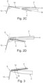
- Fig. 2C shows the effector 6 and the effector receptacle 4, which are in the non-coupled state.
- the effector holder 4 and thus the tool shaft 2 have been rotated by 180° around its longitudinal axis A. This means that the rotational distance between the effector and the effector holder is smaller than the relative positioning in Fig. 2A changed by 180° relative to each other.
- the orientation of the effector 6 is based on the line of sight of the effector recording.
- Fig. 2D shows the effector 6 and the effector holder 4, which are coupled to one another.
- the effector 6 is inserted into the effector holder 4 in such a way that an angle ⁇ 2 , which the longitudinal axis A and the saw blade 12 enclose, results from the addition of the first angle ⁇ and the second angle ⁇ .
- the angle ⁇ 2 has a value of 105°.
- the first and second angles can be changed so that any other angle combinations and thus angular positions can be created.
- Fig.3 shows Fig. 2B in a longitudinal sectional view.
- the coupling section 10 of the effector 6 is received in the effector receptacle 4 and is thus in the coupled state.
- the effector receptacle 4 has a first coupling device 14.
- This first coupling device 14 is provided on the inside of the effector receptacle 4 and is designed in the form of an elevation/rail which preferably extends over the entire width of the effector receptacle 4.
- a second coupling device 16 of the effector 6 is in engagement with the first coupling device 14 of the effector receptacle 4, i.e. the first and second coupling devices 14, 16 are in snap engagement with one another in this embodiment.
- the coupling device 16 is designed on the top side at the proximal end of the coupling section 10 of the effector 6 in the form of a groove/channel which preferably extends over the entire width of the coupling section 10.
- a second embodiment of the surgical tool is described below, which is similar to the first embodiment in its operating principle. The differences from the first embodiment are mainly presented here.
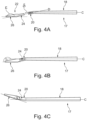
- Fig. 4A shows a surgical tool in a second embodiment, which here is a jigsaw tool.
- the tool shaft 18 has a rectangular basic shape and tapers slightly towards its distal end. At the distal end, the tool shaft 18 has the effector receptacle 20, the longitudinal axis D of which is angled at a first angle ⁇ to a longitudinal axis C of the tool shaft 18. Also shown is the effector 22, the coupling section 24 of which is angled to the working end 26 at a second angle ⁇ .
- the working end 26 has a triangular basic shape and a row of a large number of saw teeth on the underside. Even if it is not shown, the tool shaft 2 can have a coupling structure at its proximal end for coupling to a handpiece 9.
- Fig. 4B shows the effector 22 in the coupling state with the effector receptacle 20.
- the coupling section 24 is inserted into the effector receptacle 20, which is hollow. Even if it is not shown, the effector receptacle 20 can have a first coupling device and the coupling section 24 of the effector 22 can have a second coupling device similar to the first and second coupling devices 14, 16 of the first embodiment.
- An angle ⁇ 3 which the sawtooth row of the working end 26 and the longitudinal axis C of the tool shaft 18 enclose, results from the addition of the first angle ⁇ and the second angle ⁇ .
- Fig. 4C shows the starting from Fig. 4B jigsaw 17 rotated by 180° and thus branches off the Fig. 4B by 180° changed rotation distance between effector 22 and effector holder 20.
- the effector 22 is released from the coupling state before rotation and returned to the coupling state after rotation so that the working end always points downwards.
- An angle ⁇ 4 which the sawtooth row of the working end 26 and the longitudinal axis C of the tool shank 18, results from the subtraction of the first angle ⁇ from the second angle ⁇ .
- the surgical tool is an ultrasonic cutting tool in which two defined, different angular positions between effector and tool shaft are generated in the same way as in the previous two embodiments.
Landscapes
- Health & Medical Sciences (AREA)
- Surgery (AREA)
- Life Sciences & Earth Sciences (AREA)
- Heart & Thoracic Surgery (AREA)
- Nuclear Medicine, Radiotherapy & Molecular Imaging (AREA)
- Oral & Maxillofacial Surgery (AREA)
- Engineering & Computer Science (AREA)
- Biomedical Technology (AREA)
- Dentistry (AREA)
- Medical Informatics (AREA)
- Molecular Biology (AREA)
- Animal Behavior & Ethology (AREA)
- General Health & Medical Sciences (AREA)
- Public Health (AREA)
- Veterinary Medicine (AREA)
- Surgical Instruments (AREA)
Description
- Die vorliegende Offenbarung betrifft ein chirurgisches Werkzeug mit einer Effektoraufnahme am Werkzeugschaft.
- Es ist ein chirurgisches Werkzeug, insbesondere chirurgische Transversalsäge, Stichsäge oder chirurgisches Ultraschallschneidwerkzeug, bekannt, das einen, vorzugsweise schlanken, Werkzeugschaft aufweist, der an seinem proximalen Ende eine Kopplungsstruktur zur Kopplung mit einem Handstück aufweist und der zur reversiblen Kopplung des Schafts mit einem Effektor an seinem distalen Ende eine Effektoraufnahme aufweist. Die Effektoraufnahme nimmt den Effektor üblicherweise so auf, dass Effektor und Werkzeugschaft einen vorbestimmten Winkel einschließen, der unveränderlich ist. Werkzeugschäfte in unterschiedlichen Längen sind mit dem Handstück koppelbar. Je nach Indikation werden Effektoren benötigt, die unterschiedliche Winkel mit dem Werkzeugschaft einschließen. Daher muss der Anwender verschiedene Werkzeugschaft-/Effektoreinheiten vorhalten.
- Aus dem Stand der Technik sind Werkzeuge bekannt, deren Werkzeugschaft und Effektor unlösbar miteinander verbunden sind, was zu hohen Herstellungskosten führt, da an jedem Werkzeugschaft die Kopplungsgeometrie zum Koppeln mit dem Handstück angebracht werden muss. Ist der Effektor beschädigt oder defekt, muss die Werkzeugschaft-/Effektoreinheit ausgetauscht werden.
- Es gibt daher auch Werkzeuge, die einen wiederverwendbaren Werkzeugschaft mit austauschbarem Effektor vorsehen. Außerdem ist beispielsweise aus der Druckschrift
EP 1 765 188 B1 ein chirurgisches Werkzeug bekannt, dessen Effektor (Sägeblatt) direkt und reversibel/austauschbar mit dem Handstück gekoppelt ist. Ein ähnlicher Werkzeugaufbau ist auch ausUS 5 439 472 A bekannt. - Außerdem ist aus
EP 0 962 192 A1 ein Instrument mit einem Handstück, welches einen Handstückschaft und eine Haltevorrichtung aufweist, bekannt. Diese Haltevorrichtung kann ein Werkzeug aufnehmen, welches einen Werkzeugschaft und einen Effektor aufweist. Dabei weist die Haltevorrichtung ein Steckloch zur Aufnahme einer Fixiervorrichtung auf, die sich am Werkzeugschaft befindet,. Zwischen Werkzeugschaft und Effektor sind unterschiedliche Winkelstellungen möglich, indem mehrere, unterschiedlich angewinkelte Effektoren mit dem Werkzeugschaft verbunden werden können. - Diese Werkzeuge mit auswechselbarem Effektor, der mit dem Werkzeugscahft gekoppelt ist, haben den Nachteil, dass ein Anwender mehrere Werkzeugschaft-/Effektoreinheiten für verschiedene Winkelstellungen vorhalten muss. Bei einem Wechsel auf einen anderen Effektor ist daher normalerweise auch ein Werkzeugschaftwechsel erforderlich, der oftmals aufwendig unter Verwendung eines Schlüssels oder dergleichen erfolgt.
- Es ist daher ein Ziel der Erfindung, das obige Problem zu lösen und ein chirurgisches Werkzeug vorzusehen, das die Verwendung einer Werkzeugschaft-/Effektoreinheit für mindestens zwei definierte Winkelstellungen zwischen Werkzeugschaft und Effektor ermöglicht.
- Die Erfindung sieht daher ein chirurgisches Werkzeug vor, insbesondere chirurgische Transversalsäge, Stichsäge oder chirurgisches Ultraschallschneidwerkzeug, mit einem Effektor und einem, insbesondere im Vergleich mit einem Handstück schlanken, Werkzeugschaft, der an seinem proximalen Ende eine Kopplungsstruktur zur Kopplung mit dem Handstück aufweist und der zur reversiblen Kopplung des Schafts mit dem Effektor an seinem distalen Ende eine Effektoraufnahme aufweist, welche zur Längsachse des Schafts in einem vorbestimmten ersten, insbesondere spitzen, Winkel angeordnet ist. Dabei kann der Effektor über einen Kopplungsabschnitt derart mit der Effektoraufnahme gekoppelt werden, dass der Effektor und der Werkzeugschaft mit der Effektoraufnahme in zwei unterschiedliche Winkelstellungen, nämlich in genau zwei im 180° Drehabstand vorgesehene Drehpositionen, zueinander bringbar sind.
- In anderen Worten betrifft die Erfindung ein chirurgisches Werkzeug, insbesondere chirurgische Transversalsäge, Stichsäge oder chirurgisches Ultraschallschneidwerkzeug, mit einem Effektor und einem, insbesondere im Vergleich mit einem Handstück schlanken, Werkzeugschaft, der an seinem proximalen Ende eine Kopplungsstruktur zur Kopplung mit dem Handstück aufweist und der zur reversiblen Kopplung des Schafts mit dem Effektor/Werkzeugkopf an seinem distalen Ende eine Effektoraufnahme/Werkzeugkupplung/Schublade/Werkzeugaufnahme aufweist, welche zur Längsachse des Schafts in einem definierten ersten Winkel größer 0° (gekröpft) angeordnet ist. Der Effektor weist einen Kopplungsabschnitt zur reversiblen Kopplung mit dem Werkzeugschaft/dessen Effektoraufnahme sowie ein Arbeitsende auf. Durch eine Ausgestaltung der Effektoraufnahme derart, dass der Effektor in genau zwei im 180° Drehabstand vorgesehenen Drehpositionen relativ zum Werkzeugschaft mit der Effektoraufnahme koppelbar ist oder durch eine Variation des ersten Winkels/Kröpfung, bspw. durch Verbiegen der Effektoraufnahme relativ zum Werkzeugschaft, lassen sich nach der Kopplung mit dem Effektor zwei definierte Winkelstellungen zwischen Effektor(-ende) und dem Werkzeugschaft erzeugen.
- Der Vorteil der Erfindung liegt somit darin, dass durch einfaches Ändern des Drehabstandes zwischen Effektor und Werkzeugschaft/dessen Effektoraufnahme zumindest zwei definierte Winkelstellungen einstellbar sind. Damit ist der Werkzeugschaft wiederverwendbar und das Werkzeug ohne großen Aufwand für verschiedene Anforderungen verwendbar.
- Eine alternative Ausführungsform sieht vor, dass der Effektor neben dem Kopplungsabschnitt ein Arbeitsende aufweist, welches mit dem Kopplungsabschnitt einen vorbestimmten zweiten Winkel einschließt.
- Damit ist das Arbeitsende zu dem Kopplungsabschnitt unter einem definierten zweiten Winkel gebogen/gewinkelt. Durch Variation des ersten Winkels oder des zweiten Winkels, bspw. durch Verbiegen, lassen sich beliebige weitere sinnvolle Winkelkombinationen (mehr als zwei) erzeugen. Der Effektor, der für das erfindungsgemäße Werkzeug verwendet wird, ist aufgrund seiner einfachen Ausführung günstig herstellbar und kann als Einmaleffektor oder aber auch so lange verwendet werden, bis der Effektor abgenutzt ist.
- Weiterhin ist denkbar, dass der Kopplungsabschnitt des Effektors mit der Effektoraufnahme eine Hinterschneidung ausbildet.
- Durch eine derartige Hinterschneidung sitzt der Effektor fest in der Effektoraufnahme und kann sich auch bei Kraftausübung nicht einfach in einer unerwünschten Art und Weise verschieben.
- Außerdem kann vorgesehen sein, dass die Effektoraufnahme eine erste Kopplungsvorrichtung aufweist, die komplementär zu einer zweiten Kopplungsvorrichtung am Kopplungsabschnitt des Effektors ausgebildet ist, sodass die erste und die zweite Kopplungsvorrichtung als Rastverbindung oder Schnappverbindung oder Steckverbindung zusammenwirken.
- Durch eine derartige Verbindung zwischen Effektoraufnahme und Effektor kann eine sichere Aufnahme des Effektors in der Effektoraufnahme garantiert werden und ein unerwünschtes Lösen des Effektors aus der Effektoraufnahme wird unterdrückt.
- Weiter erfindungsgemäß ist ein chirurgisches Werkzeugsystem vorgesehen, das ein chirurgisches Werkzeug, wie es oben beschrieben ist, und ein Handstück zur Bedienung des chirurgischen Werkzeugs aufweist, wobei der Effektor über einen Kopplungsabschnitt reversibel mit der Effektoraufnahme koppelbar ist und der Effektor und der Werkzeugschaft in zumindest zwei unterschiedliche Winkelstellungen zueinander bringbar sind.
- Im Folgenden sind Ausführungsformen des erfindungsgemäßen chirurgischen Werkzeugs unter Bezug auf die beigefügten Zeichnungen im Detail beschrieben. Dabei werden gleichen Elementen dieselben Bezugszeichen zugewiesen. Die Ausführungsformen sind nur beispielhaft und die Erfindung ist nicht darauf begrenzt.
-
Fig. 1 ist eine perspektivische Ansicht eines chirurgischen Werkzeugs mit Werkzeugschaft und Effektor in einer ersten Ausführungsform; -
Fig. 2A ist eine Draufsicht auf einen Ausschnitt des chirurgischen Werkzeugs, die den Effektor und eine Effektoraufnahme der ersten Ausführungsform im Nicht-Koppelzustand zeigt; -
Fig. 2B ist eine Draufsicht, die den Effektor und die Effektoraufnahme ausFig. 2A im Koppelzustand zeigt; -
Fig. 2C ist eine Draufsicht, die den Effektor und die Effektoraufnahme, deren Drehposition relativ zueinander im Vergleich zuFig. 2A um 180° geändert ist, im Nicht-Koppelzustand zeigt; -
Fig. 2D ist eine Draufsicht, die den Effektor und die Effektoraufnahme ausFig. 2C im Koppelzustand zeigt; -
Fig. 3 ist zeigt eine Längsschnittansicht des Effektors und der Effektoraufnahme im Kopplungszustand; -
Fig. 4A ist eine Draufsicht auf das chirurgische Werkzeug in einer alternativen Ausführungsform, die den Effektor und die Effektoraufnahme im Nicht-Koppelzustand zeigt; -
Fig. 4B ist eine Draufsicht, die den Effektor und die Effektoraufnahme ausFig. 4A im Koppelzustand zeigt; -
Fig. 4C ist eine Draufsicht, die den Effektor und die Effektoraufnahme, deren Drehposition relativ zueinander im Vergleich zuFig. 4B um 180° geändert ist, im Koppelzustand zeigt; - Nachstehend werden Ausführungsformen der vorliegenden Offenbarung auf der Basis der zugehörigen Figuren beschrieben.
-
Fig. 1 zeigt eine perspektivische Ansicht eines chirurgischen Werkzeugs 1, das hier als Transversalsäge ausgeführt ist. Das Werkzeug 1 weist einen Werkzeugschaft 2 auf, der hier flach ausgeführt ist und in seiner Grundform rechteckig ist. Es ist aber ebenfalls möglich, dass der Werkzeugschaft 2 anderweitig, bspw. rund, ausgeführt ist. Der Werkzeugschaft 2 weist an seinem distalen Ende eine Effektoraufnahme bzw. Sägeblattaufnahme 4 auf, die in dieser Ausführungsform einstückig und starr mit dem Werkzeugschaft 2 verbunden ist. Die Effektoraufnahme 4 ist dazu vorgesehen, einen Effektor 6 aufzunehmen. Der Werkzeugschaft 2 weist an seinem proximalen Ende eine Kopplungsstruktur 8 zur Kopplung mit einem Handstück 9 auf. Die Kopplungsstuktur 8 ist hier als zur Längsachse A des Werkzeugschaftes 2 hin vertiefte Einkerbung ausgeführt, die nahe dem proximalen Ende des Werkzeugschaftes 2 angeordnet ist. Die Effektoraufnahme 4 hat eine rechteckige Grundform, die an dem Ende, das zum proximalen Ende des Werkzeugschaftes hin gerichtet ist, leicht konisch zuläuft. Der Effektor 6 ist hier als Säge ausgeführt und über den Kopplungsabschnitt 10 mit der Effektoraufnahme 4 koppelbar. Zum Kopplungsabschnitt 10 (fast senkrecht) über ein Scharnier 11 abgewinkelt ist das Arbeitsende 12 des Effektors 6 angeordnet, welches hier als Sägeblatt 12 ausgeführt ist. Der Kopplungsabschnitt 10 hat eine rechteckige Grundform. -
Fig. 2A zeigt den Effektor 6 und die Effektoraufnahme 4, die nicht miteinander im Eingriff stehen, d.h. in einem Nicht-Koppelzustand sind. Eine Längsachse B der Effektoraufnahme 4 schließt mit einer Längsachse A des Werkzeugschaftes 2 einen ersten Winkel α ein, der hier ein spitzer Winkel ist und vorzugsweise einen Wert von 7,5° hat. Der Kopplungsabschnitt 10 bildet mit dem Sägeblatt 12 einen zweiten Winkel β aus, der in dieser Darstellung größer als 90° ist, vorzugsweise 97,5°, aber auch eine andere Winkelgröße haben kann. Es ist zu erkennen, dass der Bereich des Werkzeugschaftes 2 und die Effektoraufnahme 4 in der Draufsicht eine konische Außenform aufweisen, die zum distalen Ende hin zuläuft. -
Fig. 2B zeigt den Effektor 6 und die Effektoraufnahme 4, die ausgehend vonFig. 2A miteinander in Eingriff stehen, d.h. in einem Koppelzustand sind. Im Koppelzustand bilden der Koppelabschnitt 10 des Effektors 6 und die Effektoraufnahme 4 eine Hinterschneidung aus. Ein Winkel γ1, den die Längsachse A des Werkzeugschaftes 2 und das Sägeblatt 12 einschließen, ergibt sich hier aus der Subtraktion des ersten Winkels α vom zweiten Winkel β. In dem Fall, in dem der erste Winkel α einen Wert von 7,5° hat und der zweite Winkel β einen Wert von 97,5° hat, ergibt sich für den Winkel γ1 ein Wert von 90°. -
Fig. 2C zeigt den Effektor 6 und die Effektoraufnahme 4, die in dem Nicht-Koppelzustand sind. Ausgehend vonFig. 2A ist die Effektoraufnahme 4 und damit der Werkzeugschaft 2 um dessen Längsachse A um 180° gedreht worden. Damit ist der Drehabstand zwischen Effektor und Effektoraufnahme im Vergleich zur relativen Positionierung inFig. 2A relativ zueinander um 180° geändert. Die Ausrichtung des Effektors 6 orientiert sich entlang der Verlaufsichtung der Effektoraufnahme. -
Fig. 2D zeigt den Effektor 6 und die Effektoraufnahme 4, die im Koppelzustand miteinander sind. Der Effektor 6 ist so in die Effektoraufnahme 4 eingeschoben, dass ein Winkel γ2, den die Längsachse A und das Sägeblatt 12 einschließen, sich aus der Addition des ersten Winkels α und des zweiten Winkels β ergibt. In dem Fall, in dem der erste Winkel α einen Wert von 7,5° hat und der zweite Winkel β einen Wert von 97,5° hat, ergibt sich für den Winkel γ2 ein Wert von 105°. - Aus dem Vergleich von
Fig. 2B undFig. 2D wird klar, dass es durch eine einfache Drehung des Werkzeugschaftes 2 (um dessen Längsachse A, C relativ zum Effektor 6) und die anschließende Kopplung von Effektor 6 und Effektoraufnahme 4 und damit durch Änderung des Drehabstandes zwischen Effektor 6 und Effektoraufnahme 4 möglich ist, zwei Winkelstellungen, d.h. den ersten Winkel α und den zweiten Winkel β, der sich vom ersten Winkel α unterscheidet, zwischen der Längsachse A des Werkzeugschaftes 2 und dem Effektor 6 bzw. dem Arbeitsende 12 zu erzeugen. Ein Wechsel zwischen den zwei Winkelstellungen kann somit sehr einfach und schnell durchgeführt werden. Je nach Einschub des Sägeblattes/Arbeitsendes 12 lassen sich in dieser Ausführungsform zwei definierte Winkelstellungen erzeugen. - Durch einfaches Verbiegen der Effektoraufnahme 4 gegenüber dem Werkzeugschaft 2 und/oder durch einfaches Verbiegen des Arbeitsendes 12 zum Kopplungsabschnitt 10 des Effektors 6 oder aber mithilfe eines entsprechenden Scharniers 11 am Effektor können die ersten und zweiten Winkel jeweils verändert werden, sodass sich beliebige weitere Winkelkombinationen und damit Winkelstellungen erzeugen lassen.
-
Fig. 3 zeigtFig. 2B in einer Längsschnittansicht. Der Kopplungsabschnitt 10 des Effektors 6 ist in die Effektoraufnahme 4 aufgenommen und damit im Kopplungszustand. Es ist zu erkennen, dass die Effektoraufnahme 4 eine erste Kopplungsvorrichtung 14 aufweist. Diese erste Kopplungsvorrichtung 14 ist an der Innenseite der Effektoraufnahme 4 vorgesehen und in Form einer Erhebung/Schiene ausgebildet, die sich vorzugsweise über die gesamte Breite der Effektoraufnahme 4 erstreckt. Mit der ersten Kopplungsvorrichtung 14 der Effektoraufnahme 4 steht eine zweite Kopplungsvorrichtung 16 des Effektors 6 im Eingriff, d.h., dass die erste und die zweite Kopplungsvorrichtung 14, 16 in dieser Ausführung in einem Schnappeingriff miteinander stehen. Die Kopplungsvorrichtung 16 ist oberseitig am proximalen Ende des Kopplungsabschnittes 10 des Effektors 6 in Form einer Nut/Rille ausgebildet, die sich vorzugweise über die gesamte Breite des Kopplungsabschnittes 10 erstreckt. Durch das Eingreifen der ersten Kopplungsvorrichtung 14 in die zweite Kopplungsvorrichtung 16 wird ein unerwünschtes Lösen des Effektors 6 aus der Effektoraufnahme 4 unterdrückt. Es ist zum Koppeln/zum Entkoppeln zwischen Effektoraufnahme 4 und Effektor 6 ein erhöhter Kraftaufwand in die Verlaufsrichtung der Effektoraufnahme 4 nötig, um den Schnappeingriff zwischen der ersten Kopplungsvorrichtung 14 und der zweiten Kopplungsvorrichtung 16 herzustellen/zu lösen. Auch wenn es nicht dargestellt ist, ist es denkbar, dass die Kopplungsvorrichtungen 14, 16 in einen Rasteingriff eintreten und dementsprechend anders als dargestellt ausgebildet sind. - Nachstehend wird eine zweite Ausführungsform des chirurgischen Werkzeugs beschrieben, die in ihrem Wirkprinzip ähnlich der ersten Ausführungsform ist. Es werden hierbei hauptsächlich die Unterschiede zur ersten Ausführungsform dargestellt.
-
Fig. 4A zeigt ein chirurgisches Werkzeug in einer zweiten Ausführungsform, welches hier ein Stichsägewerkzeug ist. Der Werkzeugschaft 18 hat eine rechteckige Grundform und läuft zu seinem distalen Ende hin leicht konisch zu. Am distalen Ende weist der Werkzeugschaft 18 die Effektoraunahme 20 auf, deren Längsachse D in einem ersten Winkel δ zu einer Längsachse C des Werkzeugschaftes 18 abgewinkelt ist. Weiterhin ist der Effektor 22 dargestellt, dessen Kopplungsabschnitt 24 zum Arbeitsende 26 in einem zweiten Winkel ε gewinkelt ist. Das Arbeitsende 26 hat eine dreieckige Grundform und an der Unterseite eine Reihe einer Vielzahl an Sägezähnen. Auch wenn es nicht dargestellt ist, kann der Werkzeugschaft 2 an seinem proximalen Ende eine Kopplungsstruktur zu Kopplung mit einem Handstück 9 aufweisen. -
Fig. 4B zeigt den Effektor 22 im Kopplungszustand mit der Effektoraufnahme 20. Der Kopplungsabschnitt 24 ist in die Effektoraufnahme 20 eingeschoben, welche hohl ist. Auch wenn es nicht dargestellt ist, kann die Effektoraufnahme 20 eine erste Kopplungsvorrichtung und der Kopplungsabschnitt 24 des Effektors 22 eine zweite Kopplungsvorrichtung ähnlich den ersten und zweiten Kopplungsvorrichtungen 14, 16 der ersten Ausführungsform aufweisen. Ein Winkel γ3, den die Sägezahnreihe des Arbeitsendes 26 und die Längsachse C des Werkzeugschaftes 18 einschließen, ergibt sich aus der Addition des ersten Winkels δ und des zweiten Winkels ε. -
Fig. 4C zeigt die ausgehend vonFig. 4B um 180° gedrehte Stichsäge 17 und zweigt damit den ausgehend vonFig. 4B um 180° geänderten Drehabstand zwischen Effektor 22 und Effektoraufnahme 20. Der Effektor 22 wird in dieser Ausführungsform vor der Drehung aus dem Kopplungszustand gelöst und nach der Drehung wieder in den Kopplungszustand gebracht, damit das Arbeitsende stets nach unten zeigt. Ein Winkel γ4, den die Sägezahnreihe des Arbeitsendes 26 und die Längsachse C des Werkzeugschaftes 18 einschließen, ergibt sich aus der Subtraktion des ersten Winkels δ vom zweiten Winkel ε. - Als weitere Ausführungsform ist denkbar, dass das chirurgische Werkzeug ein Ultraschallschneidwerkzeug ist, bei welchem zwei definierte, verschiedene Winkelstellungen zwischen Effektor und Werkzeugschaft auf dieselbe Weise erzeugt werden, wie bei den vorangegangen beiden Ausführungsformen.
-
- 1
- chirurgisches Werkzeug (erste Ausführungsform)
- 2
- Werkzeugschaft
- 4
- Effektoraufnahme
- 6
- Effektor
- 8
- Kopplungsstruktur
- 9
- Handstück
- 10
- Kopplungsabschnitt
- 11
- Scharnier (am Effektor)
- 12
- Arbeitsende
- 14
- erste Kopplungsvorrichtung
- 16
- zweite Kopplungsvorrichtung
- 17
- chirurgisches Werkzeug (zweite Ausführungsform)
- 18
- Werkzeugschaft
- 20
- Effektoraufnahme
- 22
- Effektor
- 24
- Kopplungsabschnitt
- 26
- Arbeitsende
- A
- Längsachse des Werkzeugschaftes in der ersten Ausführungsform
- B
- Längsachse der Effektoraufnahme in der ersten Ausführungsform
- C
- Längsachse des Werkzeugschaftes in der zweiten Ausführungsform
- D
- Längsachse des Werkzeugschaftes in der zweiten Ausführungsform
Claims (5)
- Chirurgisches Werkzeug (1, 17), insbesondere chirurgische Transversalsäge, Stichsäge oder chirurgisches Ultraschallschneidwerkzeug, mit einem Effektor (6, 22) und einem Werkzeugschaft (2, 18), der an seinem proximalen Ende eine Kopplungsstruktur (8) zur Kopplung mit einem Handstück (9) aufweist und der zur reversiblen Kopplung des Werkzeugschafts (2, 18) mit dem Effektor (6, 22) an seinem distalen Ende eine Effektoraufnahme (4, 20) aufweist, welche zur Längsachse (A, C) des Werkzeugschafts (2, 18) in einem vorbestimmten ersten, insbesondere spitzen, Winkel (α, δ) angeordnet ist,
dadurch gekennzeichnet, dass
der Effektor (6, 22) über einen Kopplungsabschnitt (10, 24) durch eine Ausgestaltung der Effektoraufnahme derart, dass der Effektor durch eine Relativdrehung zwischen Werkzeugschaft (2, 18) und Effektor (6, 22) um die Werkzeugschaft-Längsachse (A, C) in genau zwei im 180° Drehabstand vorgesehenen Drehpositionen relativ zur Effektoraufnahme koppelbar ist, mit der Effektoraufnahme (4, 20) so gekoppelt werden kann, dass der Effektor (6, 22) und der Werkzeugschaft (2, 18) in zwei unterschiedliche Winkelstellungen (γ1, γ2, γ3, γ4) zueinander bringbar sind. - Chirurgisches Werkzeug (1, 17) nach Anspruch 1, dadurch gekennzeichnet, dass
der Effektor (6, 22) neben dem Kopplungsabschnitt (10, 24) ein Arbeitsende (12, 26) aufweist, welches mit dem Kopplungsabschnitt (10, 24) einen vorbestimmten zweiten Winkel (β, ε) einschließt. - Chirurgisches Werkzeug (1, 17) nach Anspruch 1, dadurch gekennzeichnet, dass
der Kopplungsabschnitt (10, 24) des Effektors (6, 22) mit der Effektoraufnahme (4, 20) eine Hinterschneidung ausbildet. - Chirurgisches Werkzeug (1, 17) nach Anspruch 1, dadurch gekennzeichnet, dass
die Effektoraufnahme (4, 20) eine erste Kopplungsvorrichtung (14) aufweist, die komplementär zu einer zweiten Kopplungsvorrichtung (16) am Kopplungsabschnitt (10, 24) des Effektors (6, 22) ausgebildet ist, sodass die erste und die zweite Kopplungsvorrichtung (14, 16) als Rastverbindung oder Schnappverbindung oder Steckverbindung zusammenwirken. - Chirurgisches Werkzeugsystem, das das chirurgisches Werkzeug (1, 17) nach Anspruch 1 und ein Handstück (9) zur Bedienung des chirurgischen Werkzeugs (1, 17) aufweist, dadurch gekennzeichnet, dass
der Effektor (6, 22) über einen Kopplungsabschnitt (10, 24) reversibel mit der Effektoraufnahme (4, 20) koppelbar ist und der Effektor (6, 22) und der Werkzeugschaft (2, 18) in zwei unterschiedliche Winkelstellungen (γ1, γ2, γ3, γ4) zueinander bringbar sind.
Applications Claiming Priority (1)
| Application Number | Priority Date | Filing Date | Title |
|---|---|---|---|
| DE102018130381.5A DE102018130381A1 (de) | 2018-11-29 | 2018-11-29 | Chirurgisches Werkzeug mit Effektoraufnahme |
Publications (2)
| Publication Number | Publication Date |
|---|---|
| EP3685770A1 EP3685770A1 (de) | 2020-07-29 |
| EP3685770B1 true EP3685770B1 (de) | 2024-09-11 |
Family
ID=68610034
Family Applications (1)
| Application Number | Title | Priority Date | Filing Date |
|---|---|---|---|
| EP19209798.8A Active EP3685770B1 (de) | 2018-11-29 | 2019-11-18 | Chirurgisches werkzeug mit effektoraufnahme |
Country Status (2)
| Country | Link |
|---|---|
| EP (1) | EP3685770B1 (de) |
| DE (1) | DE102018130381A1 (de) |
Family Cites Families (15)
| Publication number | Priority date | Publication date | Assignee | Title |
|---|---|---|---|---|
| US2741248A (en) * | 1953-12-16 | 1956-04-10 | Allen & Hanburys Ltd | Surgical saws |
| US5263972A (en) | 1991-01-11 | 1993-11-23 | Stryker Corporation | Surgical handpiece chuck and blade |
| DE19825261A1 (de) * | 1998-06-05 | 1999-12-09 | Kaltenbach & Voigt | Medizinisches oder dentalmedizinisches Instrument zur spanabhebenden Bearbeitung von Körpergewebe und Werkzeug für ein solches Instrument |
| EP1125556A1 (de) * | 2000-02-18 | 2001-08-22 | Medsys S.A. | Uterin manipulator |
| US20100168751A1 (en) * | 2002-03-19 | 2010-07-01 | Anderson D Greg | Method, Implant & Instruments for Percutaneous Expansion of the Spinal Canal |
| GB2411856A (en) * | 2004-03-11 | 2005-09-14 | Russell Khan-Sullman Sullman | Scalpel with adjustable blade |
| US7497860B2 (en) | 2004-07-09 | 2009-03-03 | Stryker Corporation | Surgical sagittal saw including a handpiece and a removable blade assembly, the blade assembly including a guide bar, a blade head capable of oscillatory movement and a drive rod for actuating the blade head |
| US20060123959A1 (en) * | 2004-11-19 | 2006-06-15 | Elite Medical Equipment, Llc | Cutter blade for cast saw |
| EP1974881B1 (de) * | 2007-03-30 | 2013-10-23 | WSEngineering GmbH & Co. KG | Anordnung mit einer Sägeblattaufnahme für eine Oszillationssäge |
| EP2499978B1 (de) * | 2011-03-18 | 2016-08-24 | WSEngineering GmbH & Co. KG | Halterung für ein Oszillationssägeblatt |
| DE102011001545A1 (de) * | 2011-03-24 | 2012-09-27 | Aesculap Ag | Chirurgisches Sägeblatt und chirurgische Säge |
| DE102012014008A1 (de) * | 2012-07-17 | 2014-01-23 | Gernot Teichmann | Dentalwerkzeug zum Einbringen zweier schlitzförmiger Vertiefungen in einen Kieferknochen |
| DE102014207971A1 (de) * | 2014-04-28 | 2015-10-29 | Aesculap Ag | Maulteil mit Schichtaufbau für ein chirurgisches Instrument |
| US10342553B2 (en) * | 2015-01-21 | 2019-07-09 | Stryker European Holdings I, Llc | Surgical sagittal saw and complementary blade with features that fixedly hold the blade static to the saw |
| US10182829B2 (en) * | 2015-09-04 | 2019-01-22 | Depuy Ireland Unlimited Company | Surgical instrument and system of surgical instruments |
-
2018
- 2018-11-29 DE DE102018130381.5A patent/DE102018130381A1/de not_active Withdrawn
-
2019
- 2019-11-18 EP EP19209798.8A patent/EP3685770B1/de active Active
Also Published As
| Publication number | Publication date |
|---|---|
| EP3685770A1 (de) | 2020-07-29 |
| DE102018130381A1 (de) | 2020-06-04 |
Similar Documents
| Publication | Publication Date | Title |
|---|---|---|
| EP2325502B1 (de) | Anordnung und Verfahren zum Verbinden eines Zubehörteils mit einem Operationstisch | |
| EP2175707B1 (de) | Gehäuse für ein elektrisches oder elektronisches Gerät | |
| EP3658336B1 (de) | Hakenhalterung für eine werkzeugmaschine | |
| DE202004004844U1 (de) | Schraubendreher für Knochenschrauben | |
| DE112013000583B4 (de) | Sägeblattspannvorrichtung | |
| EP3025825A1 (de) | Selbstsperrende Verriegelung einer Adaptervorrichtung | |
| EP3386678A1 (de) | Vorrichtung zum automatisierten an- und abkoppeln eines werkzeugaufsatzes sowie verfahren zum automatisierten verbinden wenigstens zweier werkstücke | |
| EP3808997A1 (de) | Dübelvorrichtung | |
| DE3300697C2 (de) | Elektrische Klemme | |
| EP1709931B1 (de) | Motorelement, insbesondere dentalmedizinisches Handstück mit einer lösbaren Kupplung für einen Werkzeughalter | |
| WO2019141583A1 (de) | Ausziehführung für einen schubkasten und verfahren zum ausrichten eines schubkastens an einer ausziehführung | |
| EP3685770A1 (de) | Chirurgisches werkzeug mit effektoraufnahme | |
| DE202008017281U1 (de) | Bohrerverlängerung | |
| DE19725401C1 (de) | Bohrvorrichtung mit Begrenzung des Bohrweges | |
| EP3376060A1 (de) | Schnellverschraubung, insbesondere zum verbinden von mehrteiligen baugruppen | |
| AT509140B1 (de) | Fixiervorrichtung für einen bohrkopf | |
| EP3886734B1 (de) | Schlüssellose werkzeugschaftkopplung | |
| DE102014001500B4 (de) | Anordnung aus einem Basisgerät und einem Anbaugerät | |
| EP0989760A2 (de) | Anschlussleiste für die Telekommunikationstechnik | |
| DE102009012751A1 (de) | Vorrichtung zur vertikalen und horizontalen Positionierung von Leitschaufelträgern in das Turbinengehäuse im eingebauten Zustand | |
| DE102014115060B4 (de) | Verbindungseinrichtung | |
| DE102021104308A1 (de) | Osteosyntheseplatte | |
| EP0491185B1 (de) | Schlagknebel für eine Baugerüststütze | |
| DE202016007641U1 (de) | Blank-Halter einer Dentalfräsmaschine | |
| DE102020108260A1 (de) | Kombinationswerkzeug zur Befestigung von Schraubelementen |
Legal Events
| Date | Code | Title | Description |
|---|---|---|---|
| PUAI | Public reference made under article 153(3) epc to a published international application that has entered the european phase |
Free format text: ORIGINAL CODE: 0009012 |
|
| STAA | Information on the status of an ep patent application or granted ep patent |
Free format text: STATUS: THE APPLICATION HAS BEEN PUBLISHED |
|
| AK | Designated contracting states |
Kind code of ref document: A1 Designated state(s): AL AT BE BG CH CY CZ DE DK EE ES FI FR GB GR HR HU IE IS IT LI LT LU LV MC MK MT NL NO PL PT RO RS SE SI SK SM TR |
|
| AX | Request for extension of the european patent |
Extension state: BA ME |
|
| STAA | Information on the status of an ep patent application or granted ep patent |
Free format text: STATUS: REQUEST FOR EXAMINATION WAS MADE |
|
| 17P | Request for examination filed |
Effective date: 20200820 |
|
| RBV | Designated contracting states (corrected) |
Designated state(s): AL AT BE BG CH CY CZ DE DK EE ES FI FR GB GR HR HU IE IS IT LI LT LU LV MC MK MT NL NO PL PT RO RS SE SI SK SM TR |
|
| GRAP | Despatch of communication of intention to grant a patent |
Free format text: ORIGINAL CODE: EPIDOSNIGR1 |
|
| STAA | Information on the status of an ep patent application or granted ep patent |
Free format text: STATUS: GRANT OF PATENT IS INTENDED |
|
| INTG | Intention to grant announced |
Effective date: 20240403 |
|
| GRAS | Grant fee paid |
Free format text: ORIGINAL CODE: EPIDOSNIGR3 |
|
| GRAA | (expected) grant |
Free format text: ORIGINAL CODE: 0009210 |
|
| STAA | Information on the status of an ep patent application or granted ep patent |
Free format text: STATUS: THE PATENT HAS BEEN GRANTED |
|
| AK | Designated contracting states |
Kind code of ref document: B1 Designated state(s): AL AT BE BG CH CY CZ DE DK EE ES FI FR GB GR HR HU IE IS IT LI LT LU LV MC MK MT NL NO PL PT RO RS SE SI SK SM TR |
|
| REG | Reference to a national code |
Ref country code: GB Ref legal event code: FG4D Free format text: NOT ENGLISH |
|
| REG | Reference to a national code |
Ref country code: CH Ref legal event code: EP |
|
| REG | Reference to a national code |
Ref country code: DE Ref legal event code: R096 Ref document number: 502019012093 Country of ref document: DE |
|
| REG | Reference to a national code |
Ref country code: IE Ref legal event code: FG4D Free format text: LANGUAGE OF EP DOCUMENT: GERMAN |
|
| REG | Reference to a national code |
Ref country code: LT Ref legal event code: MG9D |
|
| PG25 | Lapsed in a contracting state [announced via postgrant information from national office to epo] |
Ref country code: NO Free format text: LAPSE BECAUSE OF FAILURE TO SUBMIT A TRANSLATION OF THE DESCRIPTION OR TO PAY THE FEE WITHIN THE PRESCRIBED TIME-LIMIT Effective date: 20241211 |
|
| REG | Reference to a national code |
Ref country code: NL Ref legal event code: MP Effective date: 20240911 |
|
| PG25 | Lapsed in a contracting state [announced via postgrant information from national office to epo] |
Ref country code: GR Free format text: LAPSE BECAUSE OF FAILURE TO SUBMIT A TRANSLATION OF THE DESCRIPTION OR TO PAY THE FEE WITHIN THE PRESCRIBED TIME-LIMIT Effective date: 20241212 Ref country code: FI Free format text: LAPSE BECAUSE OF FAILURE TO SUBMIT A TRANSLATION OF THE DESCRIPTION OR TO PAY THE FEE WITHIN THE PRESCRIBED TIME-LIMIT Effective date: 20240911 |
|
| PG25 | Lapsed in a contracting state [announced via postgrant information from national office to epo] |
Ref country code: BG Free format text: LAPSE BECAUSE OF FAILURE TO SUBMIT A TRANSLATION OF THE DESCRIPTION OR TO PAY THE FEE WITHIN THE PRESCRIBED TIME-LIMIT Effective date: 20240911 |
|
| PG25 | Lapsed in a contracting state [announced via postgrant information from national office to epo] |
Ref country code: LV Free format text: LAPSE BECAUSE OF FAILURE TO SUBMIT A TRANSLATION OF THE DESCRIPTION OR TO PAY THE FEE WITHIN THE PRESCRIBED TIME-LIMIT Effective date: 20240911 |
|
| PG25 | Lapsed in a contracting state [announced via postgrant information from national office to epo] |
Ref country code: HR Free format text: LAPSE BECAUSE OF FAILURE TO SUBMIT A TRANSLATION OF THE DESCRIPTION OR TO PAY THE FEE WITHIN THE PRESCRIBED TIME-LIMIT Effective date: 20240911 |
|
| PG25 | Lapsed in a contracting state [announced via postgrant information from national office to epo] |
Ref country code: RS Free format text: LAPSE BECAUSE OF FAILURE TO SUBMIT A TRANSLATION OF THE DESCRIPTION OR TO PAY THE FEE WITHIN THE PRESCRIBED TIME-LIMIT Effective date: 20241211 Ref country code: ES Free format text: LAPSE BECAUSE OF FAILURE TO SUBMIT A TRANSLATION OF THE DESCRIPTION OR TO PAY THE FEE WITHIN THE PRESCRIBED TIME-LIMIT Effective date: 20240911 |
|
| PG25 | Lapsed in a contracting state [announced via postgrant information from national office to epo] |
Ref country code: RS Free format text: LAPSE BECAUSE OF FAILURE TO SUBMIT A TRANSLATION OF THE DESCRIPTION OR TO PAY THE FEE WITHIN THE PRESCRIBED TIME-LIMIT Effective date: 20241211 Ref country code: NO Free format text: LAPSE BECAUSE OF FAILURE TO SUBMIT A TRANSLATION OF THE DESCRIPTION OR TO PAY THE FEE WITHIN THE PRESCRIBED TIME-LIMIT Effective date: 20241211 Ref country code: LV Free format text: LAPSE BECAUSE OF FAILURE TO SUBMIT A TRANSLATION OF THE DESCRIPTION OR TO PAY THE FEE WITHIN THE PRESCRIBED TIME-LIMIT Effective date: 20240911 Ref country code: HR Free format text: LAPSE BECAUSE OF FAILURE TO SUBMIT A TRANSLATION OF THE DESCRIPTION OR TO PAY THE FEE WITHIN THE PRESCRIBED TIME-LIMIT Effective date: 20240911 Ref country code: GR Free format text: LAPSE BECAUSE OF FAILURE TO SUBMIT A TRANSLATION OF THE DESCRIPTION OR TO PAY THE FEE WITHIN THE PRESCRIBED TIME-LIMIT Effective date: 20241212 Ref country code: FI Free format text: LAPSE BECAUSE OF FAILURE TO SUBMIT A TRANSLATION OF THE DESCRIPTION OR TO PAY THE FEE WITHIN THE PRESCRIBED TIME-LIMIT Effective date: 20240911 Ref country code: ES Free format text: LAPSE BECAUSE OF FAILURE TO SUBMIT A TRANSLATION OF THE DESCRIPTION OR TO PAY THE FEE WITHIN THE PRESCRIBED TIME-LIMIT Effective date: 20240911 Ref country code: BG Free format text: LAPSE BECAUSE OF FAILURE TO SUBMIT A TRANSLATION OF THE DESCRIPTION OR TO PAY THE FEE WITHIN THE PRESCRIBED TIME-LIMIT Effective date: 20240911 |
|
| PG25 | Lapsed in a contracting state [announced via postgrant information from national office to epo] |
Ref country code: NL Free format text: LAPSE BECAUSE OF FAILURE TO SUBMIT A TRANSLATION OF THE DESCRIPTION OR TO PAY THE FEE WITHIN THE PRESCRIBED TIME-LIMIT Effective date: 20240911 |
|
| PG25 | Lapsed in a contracting state [announced via postgrant information from national office to epo] |
Ref country code: IS Free format text: LAPSE BECAUSE OF FAILURE TO SUBMIT A TRANSLATION OF THE DESCRIPTION OR TO PAY THE FEE WITHIN THE PRESCRIBED TIME-LIMIT Effective date: 20250111 Ref country code: PT Free format text: LAPSE BECAUSE OF FAILURE TO SUBMIT A TRANSLATION OF THE DESCRIPTION OR TO PAY THE FEE WITHIN THE PRESCRIBED TIME-LIMIT Effective date: 20250113 |
|
| PG25 | Lapsed in a contracting state [announced via postgrant information from national office to epo] |
Ref country code: RO Free format text: LAPSE BECAUSE OF FAILURE TO SUBMIT A TRANSLATION OF THE DESCRIPTION OR TO PAY THE FEE WITHIN THE PRESCRIBED TIME-LIMIT Effective date: 20240911 Ref country code: SM Free format text: LAPSE BECAUSE OF FAILURE TO SUBMIT A TRANSLATION OF THE DESCRIPTION OR TO PAY THE FEE WITHIN THE PRESCRIBED TIME-LIMIT Effective date: 20240911 |
|
| PG25 | Lapsed in a contracting state [announced via postgrant information from national office to epo] |
Ref country code: EE Free format text: LAPSE BECAUSE OF FAILURE TO SUBMIT A TRANSLATION OF THE DESCRIPTION OR TO PAY THE FEE WITHIN THE PRESCRIBED TIME-LIMIT Effective date: 20240911 |
|
| PG25 | Lapsed in a contracting state [announced via postgrant information from national office to epo] |
Ref country code: CZ Free format text: LAPSE BECAUSE OF FAILURE TO SUBMIT A TRANSLATION OF THE DESCRIPTION OR TO PAY THE FEE WITHIN THE PRESCRIBED TIME-LIMIT Effective date: 20240911 Ref country code: PL Free format text: LAPSE BECAUSE OF FAILURE TO SUBMIT A TRANSLATION OF THE DESCRIPTION OR TO PAY THE FEE WITHIN THE PRESCRIBED TIME-LIMIT Effective date: 20240911 |
|
| PG25 | Lapsed in a contracting state [announced via postgrant information from national office to epo] |
Ref country code: SK Free format text: LAPSE BECAUSE OF FAILURE TO SUBMIT A TRANSLATION OF THE DESCRIPTION OR TO PAY THE FEE WITHIN THE PRESCRIBED TIME-LIMIT Effective date: 20240911 Ref country code: IT Free format text: LAPSE BECAUSE OF FAILURE TO SUBMIT A TRANSLATION OF THE DESCRIPTION OR TO PAY THE FEE WITHIN THE PRESCRIBED TIME-LIMIT Effective date: 20240911 |
|
| REG | Reference to a national code |
Ref country code: DE Ref legal event code: R097 Ref document number: 502019012093 Country of ref document: DE |
|
| PG25 | Lapsed in a contracting state [announced via postgrant information from national office to epo] |
Ref country code: MC Free format text: LAPSE BECAUSE OF FAILURE TO SUBMIT A TRANSLATION OF THE DESCRIPTION OR TO PAY THE FEE WITHIN THE PRESCRIBED TIME-LIMIT Effective date: 20240911 |
|
| PG25 | Lapsed in a contracting state [announced via postgrant information from national office to epo] |
Ref country code: DK Free format text: LAPSE BECAUSE OF FAILURE TO SUBMIT A TRANSLATION OF THE DESCRIPTION OR TO PAY THE FEE WITHIN THE PRESCRIBED TIME-LIMIT Effective date: 20240911 |
|
| PG25 | Lapsed in a contracting state [announced via postgrant information from national office to epo] |
Ref country code: LU Free format text: LAPSE BECAUSE OF NON-PAYMENT OF DUE FEES Effective date: 20241118 |
|
| PLBE | No opposition filed within time limit |
Free format text: ORIGINAL CODE: 0009261 |
|
| STAA | Information on the status of an ep patent application or granted ep patent |
Free format text: STATUS: NO OPPOSITION FILED WITHIN TIME LIMIT |
|
| 26N | No opposition filed |
Effective date: 20250612 |
|
| REG | Reference to a national code |
Ref country code: BE Ref legal event code: MM Effective date: 20241130 |
|
| PG25 | Lapsed in a contracting state [announced via postgrant information from national office to epo] |
Ref country code: SE Free format text: LAPSE BECAUSE OF FAILURE TO SUBMIT A TRANSLATION OF THE DESCRIPTION OR TO PAY THE FEE WITHIN THE PRESCRIBED TIME-LIMIT Effective date: 20240911 |
|
| PG25 | Lapsed in a contracting state [announced via postgrant information from national office to epo] |
Ref country code: BE Free format text: LAPSE BECAUSE OF NON-PAYMENT OF DUE FEES Effective date: 20241130 |
|
| PG25 | Lapsed in a contracting state [announced via postgrant information from national office to epo] |
Ref country code: IE Free format text: LAPSE BECAUSE OF NON-PAYMENT OF DUE FEES Effective date: 20241118 |
|
| REG | Reference to a national code |
Ref country code: CH Ref legal event code: U11 Free format text: ST27 STATUS EVENT CODE: U-0-0-U10-U11 (AS PROVIDED BY THE NATIONAL OFFICE) Effective date: 20251201 |
|
| PGFP | Annual fee paid to national office [announced via postgrant information from national office to epo] |
Ref country code: DE Payment date: 20251118 Year of fee payment: 7 |
|
| PGFP | Annual fee paid to national office [announced via postgrant information from national office to epo] |
Ref country code: GB Payment date: 20251120 Year of fee payment: 7 |
|
| PG25 | Lapsed in a contracting state [announced via postgrant information from national office to epo] |
Ref country code: AT Free format text: LAPSE BECAUSE OF NON-PAYMENT OF DUE FEES Effective date: 20241118 |
|
| PGFP | Annual fee paid to national office [announced via postgrant information from national office to epo] |
Ref country code: FR Payment date: 20251120 Year of fee payment: 7 |
|
| REG | Reference to a national code |
Ref country code: AT Ref legal event code: MM01 Ref document number: 1721983 Country of ref document: AT Kind code of ref document: T Effective date: 20241118 |
|
| PGFP | Annual fee paid to national office [announced via postgrant information from national office to epo] |
Ref country code: CH Payment date: 20251201 Year of fee payment: 7 |
|
| PG25 | Lapsed in a contracting state [announced via postgrant information from national office to epo] |
Ref country code: HU Free format text: LAPSE BECAUSE OF FAILURE TO SUBMIT A TRANSLATION OF THE DESCRIPTION OR TO PAY THE FEE WITHIN THE PRESCRIBED TIME-LIMIT; INVALID AB INITIO Effective date: 20191118 |
|
| PG25 | Lapsed in a contracting state [announced via postgrant information from national office to epo] |
Ref country code: CY Free format text: LAPSE BECAUSE OF FAILURE TO SUBMIT A TRANSLATION OF THE DESCRIPTION OR TO PAY THE FEE WITHIN THE PRESCRIBED TIME-LIMIT; INVALID AB INITIO Effective date: 20191118 |