EP3685769A1 - Disposable degradable hemostatic clip - Google Patents
Disposable degradable hemostatic clip Download PDFInfo
- Publication number
- EP3685769A1 EP3685769A1 EP20151884.2A EP20151884A EP3685769A1 EP 3685769 A1 EP3685769 A1 EP 3685769A1 EP 20151884 A EP20151884 A EP 20151884A EP 3685769 A1 EP3685769 A1 EP 3685769A1
- Authority
- EP
- European Patent Office
- Prior art keywords
- degradable
- sleeve
- bracket
- disposable
- hemostatic clip
- Prior art date
- Legal status (The legal status is an assumption and is not a legal conclusion. Google has not performed a legal analysis and makes no representation as to the accuracy of the status listed.)
- Granted
Links
Images



Classifications
-
- A—HUMAN NECESSITIES
- A61—MEDICAL OR VETERINARY SCIENCE; HYGIENE
- A61B—DIAGNOSIS; SURGERY; IDENTIFICATION
- A61B17/00—Surgical instruments, devices or methods
- A61B17/12—Surgical instruments, devices or methods for ligaturing or otherwise compressing tubular parts of the body, e.g. blood vessels or umbilical cord
- A61B17/122—Clamps or clips, e.g. for the umbilical cord
- A61B17/1227—Spring clips
-
- A—HUMAN NECESSITIES
- A61—MEDICAL OR VETERINARY SCIENCE; HYGIENE
- A61B—DIAGNOSIS; SURGERY; IDENTIFICATION
- A61B17/00—Surgical instruments, devices or methods
- A61B17/12—Surgical instruments, devices or methods for ligaturing or otherwise compressing tubular parts of the body, e.g. blood vessels or umbilical cord
- A61B17/122—Clamps or clips, e.g. for the umbilical cord
-
- A—HUMAN NECESSITIES
- A61—MEDICAL OR VETERINARY SCIENCE; HYGIENE
- A61B—DIAGNOSIS; SURGERY; IDENTIFICATION
- A61B17/00—Surgical instruments, devices or methods
- A61B17/12—Surgical instruments, devices or methods for ligaturing or otherwise compressing tubular parts of the body, e.g. blood vessels or umbilical cord
- A61B17/128—Surgical instruments, devices or methods for ligaturing or otherwise compressing tubular parts of the body, e.g. blood vessels or umbilical cord for applying or removing clamps or clips
-
- A—HUMAN NECESSITIES
- A61—MEDICAL OR VETERINARY SCIENCE; HYGIENE
- A61B—DIAGNOSIS; SURGERY; IDENTIFICATION
- A61B17/00—Surgical instruments, devices or methods
- A61B17/12—Surgical instruments, devices or methods for ligaturing or otherwise compressing tubular parts of the body, e.g. blood vessels or umbilical cord
- A61B17/128—Surgical instruments, devices or methods for ligaturing or otherwise compressing tubular parts of the body, e.g. blood vessels or umbilical cord for applying or removing clamps or clips
- A61B17/1285—Surgical instruments, devices or methods for ligaturing or otherwise compressing tubular parts of the body, e.g. blood vessels or umbilical cord for applying or removing clamps or clips for minimally invasive surgery
-
- A—HUMAN NECESSITIES
- A61—MEDICAL OR VETERINARY SCIENCE; HYGIENE
- A61B—DIAGNOSIS; SURGERY; IDENTIFICATION
- A61B17/00—Surgical instruments, devices or methods
- A61B2017/00004—(bio)absorbable, (bio)resorbable or resorptive
-
- A—HUMAN NECESSITIES
- A61—MEDICAL OR VETERINARY SCIENCE; HYGIENE
- A61B—DIAGNOSIS; SURGERY; IDENTIFICATION
- A61B17/00—Surgical instruments, devices or methods
- A61B2017/0023—Surgical instruments, devices or methods disposable
-
- A—HUMAN NECESSITIES
- A61—MEDICAL OR VETERINARY SCIENCE; HYGIENE
- A61B—DIAGNOSIS; SURGERY; IDENTIFICATION
- A61B17/00—Surgical instruments, devices or methods
- A61B2017/0046—Surgical instruments, devices or methods with a releasable handle; with handle and operating part separable
- A61B2017/00473—Distal part, e.g. tip or head
-
- A—HUMAN NECESSITIES
- A61—MEDICAL OR VETERINARY SCIENCE; HYGIENE
- A61B—DIAGNOSIS; SURGERY; IDENTIFICATION
- A61B17/00—Surgical instruments, devices or methods
- A61B17/12—Surgical instruments, devices or methods for ligaturing or otherwise compressing tubular parts of the body, e.g. blood vessels or umbilical cord
- A61B2017/12004—Surgical instruments, devices or methods for ligaturing or otherwise compressing tubular parts of the body, e.g. blood vessels or umbilical cord for haemostasis, for prevention of bleeding
Definitions
- a titanium alloy hemostatic clip is a commonly used metal hemostatic clip in clinical laparoscopic surgery.
- the hemostatic clip causes little toxin to human body, the permanent retention thereof in the body will cause problems of resulting in ion dissolution inflammation, disturbing the imaging diagnosis, leading to the psychological burden of patients and the like.
- the absorbable polymer hemostatic clip can be degraded in vivo, the mechanical strength of a polymer material is insufficient, resulting in a limited holding time of a clamping force and too high product cost.
- the technical problem to be solved by the present invention is to provide a disposable degradable hemostatic clip.
- a disposable degradable hemostatic clip comprising two degradable clips, a pulling bracket, a hook handle and a degradable sleeve, wherein the degradable clips are respectively arranged on two front portions of the pulling bracket; a lower part of the pulling bracket hooks with a front portion of the hook handle; and the pulling bracket and the hook handle are assembled in the degradable sleeve.
- the degradable clip and the degradable sleeve are made of Poly-L-lactic acid, and the Poly-L-lactic acid has molecular weight of more than 220,000.
- the degradable clips has a long groove in a side for clamping, the long groove being for accommodating the front portion of the pulling bracket, and having a connecting post integrated with the degradable clip; a front portion of the pulling bracket having a corresponding connecting hole.
- the long groove has a depth equal to the thickness of the pulling bracket.
- the pulling bracket has a left side bracket and a right side bracket which are symmetrical to each other, and the lower part of the pulling bracket is bent to form a connecting hook, the left side bracket and the right side bracket respectively bending outwardly from the lower part of the pulling bracket to form an arc, returning to cross with each other at a middle portion, and extending upwardly from the middle portion to form a front portion for being embedded in the long groove.
- the degradable sleeve has a limiting groove in an inner wall thereof; the degradable clip has a protruding limiting strip on an outer side wall thereof close to the degradable sleeve.
- the circlip has a plurality of connecting claws, each connecting claw sequentially passes through openings arranged in the second sleeve and corresponding openings in the degradable sleeve, so as to connect the degradable sleeve with the second sleeve.
- the hook handle connects to a control line and passes through a center hole of the circlip.
- the rear end of the second sleeve is fixed to an end of a spring tube.
- a degradable clip and a degradable sleeve are produced by using a degradable material, so that the portions of the hemostatic clip retained in the body are all degradable.
- the disposable degradable hemostatic clip also provides a metal part used in combination with the degradable part, and the mechanical strength of the degradable hemostatic clip is improved while the hemostatic clip is released, so that the practicability of the degradable hemostatic clip is greatly improved.
- the disposable degradable hemostatic clip provided by the present invention is made of a degradable material (for example, a biomedical material PLLA (Poly-L-lactic acid)) combined with a metal material (for example, a stainless steel material).
- the clip portion, for being retained in the body, of the disposable degradable hemostatic clip is made of a degradable material, and other parts that are not retained in the body can be made of a metal material. The metal parts are used to enhance the mechanical strength of the hemostatic clip.
- the two degradable clips 1 and the degradable sleeve 4 constitute a clip portion 10 (see FIG. 8 ) for being finally retained in the body, both of which are made of degradable materials.
- both can be made of a PLLA material, which is a degradable material that has been approved by the CFDA to be widely used in human body.
- the PLLA material used to make the degradable clip 1 and the degradable sleeve 4 has a molecular weight of more than 220,000.
- the mechanical strength of the PLLA material is increased by increasing the molecular weight to ensure a certain clamping force when soft tissue and blood vessels are clamped.
- the two degradable clips 1 and the degradable sleeve 4 can also be made of other degradable materials suitable for biomedical use.
- the two degradable clips 1 provided by the present invention have identical or mutually symmetrical structures. When the two degradable clips 1 are locked inside the degradable sleeve 4, the target soft tissues or target blood vessels can be clamped between the two degradable clips 1.
- a long groove 1a for accommodating the front portion 2a of the pulling bracket 2 is arranged on a facing side 10 (i.e. the side being facing each other and used for clamping) of each of the two degradable clips 1.
- the depth of the long groove 1a is equal to the thickness of the pulling bracket 2, so that after the pulling bracket 2 is embedded into the long groove 1a, the adjacent portions of the long groove 1a together with the pulling bracket 2 form a smooth surface 13 (see FIG. 6 ) to avoid accidental damage to the target soft tissues or target blood vessels.
- a protruding connecting post 1b is provided in the long groove 1a, and the connecting post 1b and the degradable clips 1 are integrated.
- the connecting post 1b is used to be matched with the connecting hole 2b provided in the front portion 2a of the pulling bracket 2, so as to connect the pulling bracket 2 to the degradable clips 1.
- An outwardly projecting limiting strip 1c is arranged on the side wall of the outer side (the side close to the degradable sleeve 4) of the degradable clip 1 to be matched with a limiting groove 4a in the inner wall of the degradable sleeve 4, so as to realize the locking function of the clip portion 10.
- the degradable sleeve 4 is a section of circular tube made of the degradable material PLLA; and the limiting groove 4a is arranged in the inner wall of the degradable sleeve 4.
- the limiting groove 4a is used for being matched with the limiting strip 1c arranged in the outer side wall 11 of the degradable clip 1, to realize the locking function.
- the degradable clip 1 is pulled into the degradable sleeve 4 by the pulling bracket 2, and the limiting strip 1c is embedded into the limiting groove 4a to lock the degradable clip 1.
- the rear portion 41 of the degradable sleeve 4 is provided with a thin wall to be inserted with the front portion 51 of the second sleeve 5.
- a row of openings 40 of equal height is formed in the thin wall at the rear portion 41 of the degradable sleeve 4 to achieve the connection with the second sleeve 5.
- All of the pulling brackets 2, the hook handle 3, the second sleeve 5 and the circlip 6 are all of stainless steel material.
- the degradable clip 1 is provided with the pulling bracket 2 and the hook handle 3 made of stainless steel material, so as to provide a mechanical support for the degradable clip 1, and to pull the degradable clip 1 to move, thereby realizing the closure and lock separation of the two degradable clips 1.
- the pulling bracket 2 is an integral elastic bracket formed by twisting and deforming one metal piece, and substantially has a shape of "8".
- the pulling bracket 2 has two parts, a left side bracket 25a and a right side bracket 25b, which are bilaterally symmetrical to each other.
- the lower part 20 of the pulling bracket 2 is bent into a connecting hook 2c.
- the left side bracket 25a and the right side bracket 25b are respectively bent outside from the connecting hook 2c of the pulling bracket 2 to respectively form an arc, then returned inside to the middle potion 21 to be crossed with each other, and continue to extend upward to respectively form a front portion 2a to be embedded in the long groove 1a.
- a connecting hole 2b is formed in each front portion 2a of the pulling bracket 2.
- the connecting holes 2b are used to be matched with the corresponding connecting posts 1b, thereby fixing the degradable clips 1 to the corresponding front portions 2a of the pulling bracket 2.
- an outwardly protruding arc 2d is respectively formed at the portion where the left side bracket 25a and the right side bracket 25b respectively extend to the front portions 2a upper than the middle portion 21 that the left side bracket 25a and the right side bracket 25b cross each other.
- the outermost side of the arc 2d and the outer side wall 11 of the degradable clip 1 are coplanar, whose height are substantially equal, when the degradable clip 1 is installed at the front portion 2a of the pulling bracket 2, so that the degradable clip 1 can enter the degradable sleeve 4 smoothly during movement of the pulling bracket 2.
- metal parts used in combination with the degradable part are also provided.
- the present invention realizes the separation and retention of the degradable clip portion, improves the mechanical strength of the disposable degradable hemostatic clip during operation, and thus greatly improves practicability of the degradable hemostatic clip.
Landscapes
- Health & Medical Sciences (AREA)
- Surgery (AREA)
- Life Sciences & Earth Sciences (AREA)
- Heart & Thoracic Surgery (AREA)
- Nuclear Medicine, Radiotherapy & Molecular Imaging (AREA)
- Vascular Medicine (AREA)
- Engineering & Computer Science (AREA)
- Biomedical Technology (AREA)
- Reproductive Health (AREA)
- Medical Informatics (AREA)
- Molecular Biology (AREA)
- Animal Behavior & Ethology (AREA)
- General Health & Medical Sciences (AREA)
- Public Health (AREA)
- Veterinary Medicine (AREA)
- Surgical Instruments (AREA)
Abstract
Description
- The present invention relates to a disposable degradable hemostatic clip, belonging to the technical field of medical instruments.
- Laparoscopic surgery began in the 1980. In China, this minimally invasive surgery was introduced in the early 1990s. During the surgery, a hemostatic clip is frequently used clinically to stop bleeding, the operation is relatively easy, and the effect of hemostasis is better. The more commonly used hemostatic clip materials are mainly non-degradable metal materials and degradable polymer hemostatic clips. Both types of hemostatic clips are used clinically, but both have certain problems.
- Currently, a titanium alloy hemostatic clip is a commonly used metal hemostatic clip in clinical laparoscopic surgery. Although the hemostatic clip causes little toxin to human body, the permanent retention thereof in the body will cause problems of resulting in ion dissolution inflammation, disturbing the imaging diagnosis, leading to the psychological burden of patients and the like. Although the absorbable polymer hemostatic clip can be degraded in vivo, the mechanical strength of a polymer material is insufficient, resulting in a limited holding time of a clamping force and too high product cost.
- In addition, improvements to the degradable hemostatic clips are now being largely focused on improving the material of the hemostatic clip, so that a structural design used in conjunction with a degradable material is in need.
- The technical problem to be solved by the present invention is to provide a disposable degradable hemostatic clip.
- In order to achieve the above technical purpose, the present invention adopts the following technical solutions:
A disposable degradable hemostatic clip, comprising two degradable clips, a pulling bracket, a hook handle and a degradable sleeve, wherein the degradable clips are respectively arranged on two front portions of the pulling bracket; a lower part of the pulling bracket hooks with a front portion of the hook handle; and the pulling bracket and the hook handle are assembled in the degradable sleeve. - Preferably, the degradable clip and the degradable sleeve are made of Poly-L-lactic acid, and the Poly-L-lactic acid has molecular weight of more than 220,000.
- Preferably, the degradable clips has a long groove in a side for clamping,
the long groove being for accommodating the front portion of the pulling bracket, and having a connecting post integrated with the degradable clip;
a front portion of the pulling bracket having a corresponding connecting hole. - Preferably, the long groove has a depth equal to the thickness of the pulling bracket.
- Preferably, the pulling bracket has a left side bracket and a right side bracket which are symmetrical to each other, and the lower part of the pulling bracket is bent to form a connecting hook,
the left side bracket and the right side bracket respectively bending outwardly from the lower part of the pulling bracket to form an arc, returning to cross with each other at a middle portion, and extending upwardly from the middle portion to form a front portion for being embedded in the long groove. - Preferably, between the middle portion and the front portion, the left side bracket and the right side bracket respectively forms an outwardly protruding arc,
the arc having an outermost side which are coplanar with an outer side wall of the degradable clip, whose heights are substantially equal. - Preferably, the degradable sleeve has a limiting groove in an inner wall thereof;
the degradable clip has a protruding limiting strip on an outer side wall thereof close to the degradable sleeve. - Preferably, the circlip has a plurality of connecting claws, each connecting claw sequentially passes through openings arranged in the second sleeve and corresponding openings in the degradable sleeve, so as to connect the degradable sleeve with the second sleeve.
- Preferably, the hook handle connects to a control line and passes through a center hole of the circlip.
- Preferably, the rear end of the second sleeve is fixed to an end of a spring tube.
- According to the disposable degradable hemostatic clip provided by the present invention, a degradable clip and a degradable sleeve are produced by using a degradable material, so that the portions of the hemostatic clip retained in the body are all degradable. At the same time, the disposable degradable hemostatic clip also provides a metal part used in combination with the degradable part, and the mechanical strength of the degradable hemostatic clip is improved while the hemostatic clip is released, so that the practicability of the degradable hemostatic clip is greatly improved.
-
-
FIG. 1 is an exploded view of a disposable degradable hemostatic clip provided by the present invention; -
FIG. 2A and FIG. 2B are schematic front view and schematic side view of a degradable clip respectively; -
FIG. 3 is a schematic structural view of a pulling bracket; -
FIG. 4 is a schematic structural view of a hook handle; -
FIG. 5A andFIG. 5B are schematic top view and schematic front view of a circlip respectively; -
FIG. 6 is a schematic structural view of the assembled disposable degradable hemostatic clip; -
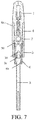
FIG. 7 is a schematic view showing a state in which the degradable clip is closed and locked; -
FIG. 8 is a schematic view showing the structure of a degradable portion retained in the body. - The technical solutions of the present invention are further described in detail below in combination with the accompanying drawings and specific embodiments.
- The disposable degradable hemostatic clip provided by the present invention is made of a degradable material (for example, a biomedical material PLLA (Poly-L-lactic acid)) combined with a metal material (for example, a stainless steel material). The clip portion, for being retained in the body, of the disposable degradable hemostatic clip is made of a degradable material, and other parts that are not retained in the body can be made of a metal material. The metal parts are used to enhance the mechanical strength of the hemostatic clip.
- Specifically, as shown in
FIG. 1 , the disposable degradable hemostatic clip provided by the present invention comprises twodegradable clips 1, apulling bracket 2, ahook handle 3, adegradable sleeve 4, asecond sleeve 5, acirclip 6, a control handle and accessories for being used in cooperation with the control handle. - The two
degradable clips 1 and thedegradable sleeve 4 constitute a clip portion 10 (seeFIG. 8 ) for being finally retained in the body, both of which are made of degradable materials. For example, both can be made of a PLLA material, which is a degradable material that has been approved by the CFDA to be widely used in human body. In the present invention, the PLLA material used to make thedegradable clip 1 and thedegradable sleeve 4 has a molecular weight of more than 220,000. The mechanical strength of the PLLA material is increased by increasing the molecular weight to ensure a certain clamping force when soft tissue and blood vessels are clamped. Although increasing the molecular weight will delay the complete degradation time of PLLA, since the PLLA material will eventually be completely degraded, it is resolved that the non-degradable materials retained in the body due to the non-degradable titanium clip or the like cause other adverse reactions during some current endoscopic treatment. Of course, the twodegradable clips 1 and thedegradable sleeve 4 can also be made of other degradable materials suitable for biomedical use. - The two
degradable clips 1 provided by the present invention have identical or mutually symmetrical structures. When the twodegradable clips 1 are locked inside thedegradable sleeve 4, the target soft tissues or target blood vessels can be clamped between the twodegradable clips 1. - As shown in
FIG. 2A and FIG. 2B , a long groove 1a for accommodating thefront portion 2a of thepulling bracket 2 is arranged on a facing side 10 (i.e. the side being facing each other and used for clamping) of each of the twodegradable clips 1. The depth of the long groove 1a is equal to the thickness of thepulling bracket 2, so that after thepulling bracket 2 is embedded into the long groove 1a, the adjacent portions of the long groove 1a together with thepulling bracket 2 form a smooth surface 13 (seeFIG. 6 ) to avoid accidental damage to the target soft tissues or target blood vessels. A protruding connectingpost 1b is provided in the long groove 1a, and the connectingpost 1b and thedegradable clips 1 are integrated. The connectingpost 1b is used to be matched with the connectinghole 2b provided in thefront portion 2a of thepulling bracket 2, so as to connect thepulling bracket 2 to thedegradable clips 1. An outwardly projecting limiting strip 1c is arranged on the side wall of the outer side (the side close to the degradable sleeve 4) of thedegradable clip 1 to be matched with a limiting groove 4a in the inner wall of thedegradable sleeve 4, so as to realize the locking function of the clip portion 10. - The
degradable sleeve 4 is a section of circular tube made of the degradable material PLLA; and the limiting groove 4a is arranged in the inner wall of thedegradable sleeve 4. The limiting groove 4a is used for being matched with the limiting strip 1c arranged in theouter side wall 11 of thedegradable clip 1, to realize the locking function. As shown inFIG. 7 , thedegradable clip 1 is pulled into thedegradable sleeve 4 by the pullingbracket 2, and the limiting strip 1c is embedded into the limiting groove 4a to lock thedegradable clip 1. Therear portion 41 of thedegradable sleeve 4 is provided with a thin wall to be inserted with thefront portion 51 of thesecond sleeve 5. A row ofopenings 40 of equal height is formed in the thin wall at therear portion 41 of thedegradable sleeve 4 to achieve the connection with thesecond sleeve 5. - Other parts used in cooperation with the above-mentioned degradable clip portion 10 are described below. All of the pulling
brackets 2, thehook handle 3, thesecond sleeve 5 and thecirclip 6 are all of stainless steel material. Thedegradable clip 1 is provided with the pullingbracket 2 and the hook handle 3 made of stainless steel material, so as to provide a mechanical support for thedegradable clip 1, and to pull thedegradable clip 1 to move, thereby realizing the closure and lock separation of the twodegradable clips 1. - As shown in
FIG. 3 , the pullingbracket 2 is an integral elastic bracket formed by twisting and deforming one metal piece, and substantially has a shape of "8". The pullingbracket 2 has two parts, aleft side bracket 25a and aright side bracket 25b, which are bilaterally symmetrical to each other. Thelower part 20 of the pullingbracket 2 is bent into a connectinghook 2c. Theleft side bracket 25a and theright side bracket 25b are respectively bent outside from the connectinghook 2c of the pullingbracket 2 to respectively form an arc, then returned inside to themiddle potion 21 to be crossed with each other, and continue to extend upward to respectively form afront portion 2a to be embedded in the long groove 1a. A connectinghole 2b is formed in eachfront portion 2a of the pullingbracket 2. The connectingholes 2b are used to be matched with the corresponding connectingposts 1b, thereby fixing thedegradable clips 1 to the correspondingfront portions 2a of the pullingbracket 2. Further, an outwardlyprotruding arc 2d is respectively formed at the portion where theleft side bracket 25a and theright side bracket 25b respectively extend to thefront portions 2a upper than themiddle portion 21 that theleft side bracket 25a and theright side bracket 25b cross each other. The outermost side of thearc 2d and theouter side wall 11 of thedegradable clip 1 are coplanar, whose height are substantially equal, when thedegradable clip 1 is installed at thefront portion 2a of the pullingbracket 2, so that thedegradable clip 1 can enter thedegradable sleeve 4 smoothly during movement of the pullingbracket 2. - As shown in
FIG. 4 , thefront portion 30 of the hook handle 3 has a larger diameter than that of the connectingrod 3b, and is provided with a hook-shapedgroove 3a for matching with the hook shape of the connectinghook 2c. The pullingbracket 2 is hooked with the hook handle 3 when the connectinghook 2c at thelower part 20 of the pullingbracket 2 edges into the hook-shapedgroove 3a at thefront portion 30 of thehook handle 3. The rear portion of the hook handle 3 is cylindrical connectingrod 3b. The hook handle 3 is connected with a control wire by the means of inserting and fixing the control wire from the tail end of the hook handle 3 to the connectingrod 3b. - The
second sleeve 5 is a circular tube. Thefront portion 51 of thesecond sleeve 5 is a wall which is thinned from the outside, so that the outer diameter of the thin wall at thefront portion 51 of thesecond sleeve 5 is equal to the inner diameter of the thin wall at therear portion 41 of thedegradable sleeve 4. A circle ofopenings 50 of equal height is provided on the thin wall at thefront portion 51 of thesecond sleeve 5, and theopenings 50 provided at thefront portion 51 of thesecond sleeve 5 correspond to theopenings 40 provided at therear portion 41 of thedegradable sleeve 4. - The
circlip 6 as shown inFIG. 5 is composed of aring portion 6a and a plurality of connectingclaws 6c integrated with thering portion 6a. Acenter hole 6b is formed at the center of thering portion 6a, and the connectingclaws 6c are evenly arranged on the outer circumference of thering portion 6a. Thesecond sleeve 5 is connected with thedegradable sleeve 4 when the connectingclaws 6c are sequentially inserted into theopenings 50 in thesecond sleeve 5 and theopenings 40 correspondingly provided in thedegradable sleeve 4. In this embodiment, thecirclip 6 is provided with three connectingclaws 6c, and three openings (40, 50) corresponding to the connectingclaws 6c are respectively arranged on thedegradable sleeve 4 and thesecond sleeve 5. The order of which the connectingclaws 6c are inserted into thedegradable sleeve 4 and thesecond sleeve 5 may be reversed, depending on the structure of thedegradable sleeve 4 and thesecond sleeve 5. At the time of connecting thedegradable sleeve 4 with thesecond sleeve 5, thedegradable sleeve 4 with thesecond sleeve 5 are first fastened together, and then the connectingclaws 6c of thecirclip 6 are inserted into the corresponding openings (40, 50) so as to complete the connection of thedegradable sleeve 4 with thesecond sleeve 5. After thedegradable sleeve 4 and thesecond sleeve 5 are connected, therear portion 3b of the hook handle 3 passes through thecenter hole 6b of thecirclip 6 and is connected to the control wire. The diameter of thecenter hole 6b is larger than the diameter of the connectingrod 3b at the rear portion of thehook handle 3, but smaller than the diameter of thefront portion 30 of thehook handle 3. If the hook handle 3 is pulled backward so that thefront portion 30 of the hook handle 3 acts on thecenter hole 6b of thecirclip 6, thecirclip 6 is forced to deform, thereby the connectingclaws 6c of thecirclip 6 being constrained, and thus thedegradable sleeve 4 and thesecond sleeve 5 are disconnected. - The assembly process of the disposable degradable hemostatic clip provided by the present invention is described below.
- At the time of assembling the disposable degradable hemostatic clip, firstly, the two
degradable clips 1 are installed at the front portion of the pullingbracket 2, and helower part 20 of the pullingbracket 2 is hooked with thefront portion 30 of thehook handle 3. Secondly, thedegradable sleeve 4 and thesecond sleeve 5 are inserted together, and then are fixed together by thecirclip 6. Thirdly, the hook handle 3 is passed through thecenter hole 6b of thecirclip 6 and then connected to the control line. Finally, thecirclip 6 is connected to thesecond sleeve 5 to complete the assembly process of the disposable degradable hemostatic clip. - As described above, the disposable degradable hemostatic clip provided by the present invention has a structure as shown in
FIG. 6 when not in use. Twodegradable clips 1 are respectively fixed at the front portion of the pullingbracket 2, and the connectinghook 2c of the pullingbracket 2 is hooked to the hook-shapedgroove 3a of thehook handle 3. Thedegradable sleeve 4 and thesecond sleeve 5 cover the outside of the pullingbracket 2 and thehook handle 3. Thedegradable sleeve 4 and thesecond sleeve 5 are assembled together by thecirclip 6. The rear portion of the hook handle 3 is connected to the control line and passes through thecenter hole 6b thecirclip 6. The control wire passes through the spring tube and is connected to a control knob on the control handle (not showing). The rear end of thesecond sleeve 5 is fixed to one end of the spring tube, and the other end of the spring tube is fixed to the housing of the control handle. Due to an arranged positioning block mechanism on the control handle, thedegradable clip 1 can only partially enter thedegradable sleeve 4 so that the clip portion assumes a closed initial state. Thedegradable clip 1 can also be opened and closed again when a bracelet connected to the hook handle 3 is pushed. - In the process of use, the hook handle 3 is pulled backward so as to pull the pulling
bracket 2. Consequently, the twodegradable clips 1 are driven into thedegradable sleeve 4. Then the twodegradable clips 1 are closed, so that the twodegradable clips 1 are locked inside the degradable sleeve 4 (as shown inFIG. 7 ). Subsequently, the hook handle 3 is continuously pulled backward, and the pullingbracket 2 is driven by the hook handle 3 to break the connectingpost 1b, and thus the pullingbracket 2 is separated from thedegradable clip 1. The hook handle 3 is continuously pulled, thecirclip 6 is forced by the hook handle 3 to deform, and the three connectingclaws 6c of thecirclip 6 retreat so as to retract from theopenings 40 of thedegradable sleeve 4, thereby separating thesecond sleeve 5 from thedegradable sleeve 4. Thus, thedegradable clip 1 and thedegradable sleeve 4 as shown inFIG. 8 are retained in the body, the rest made of a metal material (including the pullingbracket 2, thehook handle 3, thesecond sleeve 5, and the circlip 6) are withdrawn from the body through the channel of biopsy forceps of endoscope along with the spring tube and the control line (not showing). - In summary, a disposable degradable hemostatic clip provided by the present invention comprises a degradable clip and a degradable sleeve made of a degradable material, so that the clip portion retains in the body can be degraded. At the same time, metal parts used in combination with the degradable part are also provided. The present invention realizes the separation and retention of the degradable clip portion, improves the mechanical strength of the disposable degradable hemostatic clip during operation, and thus greatly improves practicability of the degradable hemostatic clip.
- The disposable degradable hemostatic clip provided by the present invention are described in detail above. For those of ordinary skill in the art, any obvious changes made to the present invention is included in the present invention, and will constitutes an infringement of the patent right of the present invention and bear corresponding legal liabilities.
Claims (10)
- A disposable degradable hemostatic clip, comprising two degradable clips, a pulling bracket, a hook handle and a degradable sleeve, wherein the degradable clips are respectively arranged on two front portions of the pulling bracket; a lower part of the pulling bracket hooks with a front portion of the hook handle; and the pulling bracket and the hook handle are assembled in the degradable sleeve.
- The disposable degradable hemostatic clip according to claim 1, wherein
the degradable clip and the degradable sleeve are made of Poly-L-lactic acid, and the Poly-L-lactic acid has molecular weight of more than 220,000. - The disposable degradable hemostatic clip according to claim 1, wherein
the degradable clips has a long groove in a side for clamping,
the long groove being for accommodating the front portion of the pulling bracket, and having a connecting post integrated with the degradable clip;
a front portion of the pulling bracket having a corresponding connecting hole. - The disposable degradable hemostatic clip according to claim 3, wherein
the long groove has a depth equal to the thickness of the pulling bracket. - The disposable degradable hemostatic clip according to claim 3, wherein
the pulling bracket has a left side bracket and a right side bracket which are symmetrical to each other, and the lower part of the pulling bracket is bent to form a connecting hook,
the left side bracket and the right side bracket respectively bending outwardly from the lower part of the pulling bracket to form an arc, returning to cross with each other at a middle portion, and extending upwardly from the middle portion to form a front portion for being embedded in the long groove. - The disposable degradable hemostatic clip according to claim 5, wherein
between the middle portion and the front portion, the left side bracket and the right side bracket respectively forms an outwardly protruding arc,
the arc having an outermost side which are coplanar with an outer side wall of the degradable clip, whose heights are substantially equal. - The disposable degradable hemostatic clip according to claim 1, wherein
the degradable sleeve has a limiting groove in an inner wall thereof;
the degradable clip has a protruding limiting strip on an outer side wall thereof close to the degradable sleeve. - The disposable degradable hemostatic clip according to claim 1, further comprising a circlip and a second sleeve, wherein
the circlip has a plurality of connecting claws, each connecting claw sequentially passes through openings arranged in the second sleeve and corresponding openings in the degradable sleeve, so as to connect the degradable sleeve with the second sleeve. - The disposable degradable hemostatic clip according to claim 8, wherein the hook handle connects to a control line and passes through a center hole of the circlip.
- The disposable degradable hemostatic clip according to claim 8, wherein the rear end of the second sleeve is fixed to an end of a spring tube.
Applications Claiming Priority (2)
| Application Number | Priority Date | Filing Date | Title |
|---|---|---|---|
| CN201920105830.9U CN209713038U (en) | 2019-01-22 | 2019-01-22 | Disposable degradable hemostatic clamp |
| CN201910060262.XA CN109620344B (en) | 2019-01-22 | 2019-01-22 | Disposable degradable hemostatic clip |
Publications (3)
| Publication Number | Publication Date |
|---|---|
| EP3685769A1 true EP3685769A1 (en) | 2020-07-29 |
| EP3685769B1 EP3685769B1 (en) | 2026-03-04 |
| EP3685769C0 EP3685769C0 (en) | 2026-03-04 |
Family
ID=69172646
Family Applications (1)
| Application Number | Title | Priority Date | Filing Date |
|---|---|---|---|
| EP20151884.2A Active EP3685769B1 (en) | 2019-01-22 | 2020-01-15 | Disposable degradable hemostatic clip |
Country Status (3)
| Country | Link |
|---|---|
| US (1) | US11234707B2 (en) |
| EP (1) | EP3685769B1 (en) |
| ES (1) | ES3064357T3 (en) |
Families Citing this family (6)
| Publication number | Priority date | Publication date | Assignee | Title |
|---|---|---|---|---|
| US11944321B2 (en) * | 2021-01-26 | 2024-04-02 | Olympus Medical Systems Corp. | Endoscopic treatment device |
| US11937828B2 (en) | 2021-01-26 | 2024-03-26 | Olympus Medical Systems Corp. | Endoscope treatment device |
| DE112021006770T5 (en) | 2021-03-08 | 2023-11-16 | Olympus Medical Systems Corp. | Endoscopic treatment device |
| CN113974756A (en) * | 2021-10-22 | 2022-01-28 | 大连医科大学附属第一医院 | Hemostatic clamp with degradation loosening structure used under endoscope inspection |
| CN114938981A (en) * | 2022-04-21 | 2022-08-26 | 中国人民解放军联勤保障部队第九二三医院 | An absorbable stapler |
| CN117297699B (en) * | 2023-11-14 | 2025-10-24 | 江苏博朗森思医疗器械有限公司 | A continuous hemostatic clamp that can be bent and opened and closed repeatedly |
Citations (2)
| Publication number | Priority date | Publication date | Assignee | Title |
|---|---|---|---|---|
| US20070293875A1 (en) * | 2006-03-10 | 2007-12-20 | Wilson-Cook Medical, Inc. | Clip device and protective cap, and methods of using the protective cap and clip device with an endoscope for grasping tissue endoscopically |
| US20180125497A1 (en) * | 2007-05-03 | 2018-05-10 | Boston Scientific Scimed, Inc. | Single Stage Hemostasis Clipping Device |
Family Cites Families (6)
| Publication number | Priority date | Publication date | Assignee | Title |
|---|---|---|---|---|
| US7357805B2 (en) * | 2001-12-13 | 2008-04-15 | Sumitomo Bakelite Company | Clip device for endoscope and clip for endoscope for use therein |
| US7727247B2 (en) * | 2002-08-21 | 2010-06-01 | Olympus Corporation | Living tissue ligation device |
| EP2528541B1 (en) * | 2010-01-28 | 2016-05-18 | Covidien LP | Vascular remodeling device |
| WO2013130595A1 (en) * | 2012-02-28 | 2013-09-06 | Boston Scientific Scimed, Inc. | Clip applier |
| BR112017009196B1 (en) * | 2014-11-03 | 2021-12-14 | Oregon Health & Science University | SURGICAL CLIP, SET OF SURGICAL CLIPS FOR ONE SURGICAL CLIP APPLICATOR, AND SURGICAL CLIP APPLICATOR |
| WO2019147485A1 (en) * | 2018-01-29 | 2019-08-01 | Boston Scientific Scimed, Inc. | Hemostasis clip |
-
2019
- 2019-12-30 US US16/730,874 patent/US11234707B2/en active Active
-
2020
- 2020-01-15 EP EP20151884.2A patent/EP3685769B1/en active Active
- 2020-01-15 ES ES20151884T patent/ES3064357T3/en active Active
Patent Citations (2)
| Publication number | Priority date | Publication date | Assignee | Title |
|---|---|---|---|---|
| US20070293875A1 (en) * | 2006-03-10 | 2007-12-20 | Wilson-Cook Medical, Inc. | Clip device and protective cap, and methods of using the protective cap and clip device with an endoscope for grasping tissue endoscopically |
| US20180125497A1 (en) * | 2007-05-03 | 2018-05-10 | Boston Scientific Scimed, Inc. | Single Stage Hemostasis Clipping Device |
Also Published As
| Publication number | Publication date |
|---|---|
| EP3685769B1 (en) | 2026-03-04 |
| US11234707B2 (en) | 2022-02-01 |
| EP3685769C0 (en) | 2026-03-04 |
| ES3064357T3 (en) | 2026-04-24 |
| US20200229823A1 (en) | 2020-07-23 |
Similar Documents
| Publication | Publication Date | Title |
|---|---|---|
| EP3685769B1 (en) | Disposable degradable hemostatic clip | |
| CN213430373U (en) | Absorbable hemostatic clamp used in cooperation with endoscope | |
| CN109620344B (en) | Disposable degradable hemostatic clip | |
| US11013518B2 (en) | Detachable endoscopic clip for anastomosis | |
| AU2019452937B2 (en) | Clamp device used in cooperation with endoscope, and clamping portion of clamp device | |
| US9510836B2 (en) | Living tissue ligation device | |
| JP3134287B2 (en) | Catheter assembly for endocardial suture surgery | |
| CN102076271B (en) | Endoscopic compression clip and system and method for use thereof | |
| CN109805977A (en) | A kind of Medical hemostatic clamp | |
| US20030097146A1 (en) | Endoscopic surgical instrument | |
| JPH09108228A (en) | Catheter assembly for endocardial suture surgery | |
| CN111526804B (en) | Double support jaw design | |
| JPH10211206A (en) | Endocardial suture surgery tool | |
| EP4079230A1 (en) | Occluder, occluder system, and conveying device | |
| US20240225629A1 (en) | Clip instruments | |
| CN110251186A (en) | A chuck structure of tissue clip for endoscope | |
| JP2008543354A (en) | Ligation clip with reduced closing force | |
| US20220133326A1 (en) | Hemostatic clip | |
| US20210100668A1 (en) | Thermopuncture stent implantation device | |
| CN211560230U (en) | Cavity way closing device under scope | |
| US8728094B2 (en) | Percutaneous aneurysm inversion and ligation | |
| CN209713038U (en) | Disposable degradable hemostatic clamp | |
| CN211049500U (en) | Hemostatic clamp | |
| CN117015350A (en) | Ligation clip including flexible insertion component | |
| US9320596B2 (en) | Dilator for inserting a voice prosthesis |
Legal Events
| Date | Code | Title | Description |
|---|---|---|---|
| PUAI | Public reference made under article 153(3) epc to a published international application that has entered the european phase |
Free format text: ORIGINAL CODE: 0009012 |
|
| STAA | Information on the status of an ep patent application or granted ep patent |
Free format text: STATUS: REQUEST FOR EXAMINATION WAS MADE |
|
| 17P | Request for examination filed |
Effective date: 20200204 |
|
| AK | Designated contracting states |
Kind code of ref document: A1 Designated state(s): AL AT BE BG CH CY CZ DE DK EE ES FI FR GB GR HR HU IE IS IT LI LT LU LV MC MK MT NL NO PL PT RO RS SE SI SK SM TR |
|
| AX | Request for extension of the european patent |
Extension state: BA ME |
|
| STAA | Information on the status of an ep patent application or granted ep patent |
Free format text: STATUS: EXAMINATION IS IN PROGRESS |
|
| 17Q | First examination report despatched |
Effective date: 20230503 |
|
| GRAP | Despatch of communication of intention to grant a patent |
Free format text: ORIGINAL CODE: EPIDOSNIGR1 |
|
| STAA | Information on the status of an ep patent application or granted ep patent |
Free format text: STATUS: GRANT OF PATENT IS INTENDED |
|
| RIC1 | Information provided on ipc code assigned before grant |
Ipc: A61B 17/122 20060101AFI20250903BHEP Ipc: A61B 17/128 20060101ALI20250903BHEP Ipc: A61B 17/00 20060101ALN20250903BHEP |
|
| INTG | Intention to grant announced |
Effective date: 20250916 |
|
| GRAS | Grant fee paid |
Free format text: ORIGINAL CODE: EPIDOSNIGR3 |
|
| GRAA | (expected) grant |
Free format text: ORIGINAL CODE: 0009210 |
|
| STAA | Information on the status of an ep patent application or granted ep patent |
Free format text: STATUS: THE PATENT HAS BEEN GRANTED |
|
| REG | Reference to a national code |
Ref country code: DE Ref legal event code: R081 Ref document number: 602020067835 Country of ref document: DE Owner name: BEIJING DONGLIN FUSHI MEDICAL DEVICES CO., LTD, CN Free format text: FORMER OWNERS: BEIJING DONGLIN FUSHI MEDICAL DEVICES CO., LTD., BEIJING, CN; YU, CHUN, BEIJING, CN; YU, LING, BEIJING, CN Ref country code: DE Ref legal event code: R081 Ref document number: 602020067835 Country of ref document: DE Owner name: YU, CHUN, CN Free format text: FORMER OWNERS: BEIJING DONGLIN FUSHI MEDICAL DEVICES CO., LTD., BEIJING, CN; YU, CHUN, BEIJING, CN; YU, LING, BEIJING, CN Ref country code: DE Ref legal event code: R081 Ref document number: 602020067835 Country of ref document: DE Owner name: YU, LING, CN Free format text: FORMER OWNERS: BEIJING DONGLIN FUSHI MEDICAL DEVICES CO., LTD., BEIJING, CN; YU, CHUN, BEIJING, CN; YU, LING, BEIJING, CN |
|
| AK | Designated contracting states |
Kind code of ref document: B1 Designated state(s): AL AT BE BG CH CY CZ DE DK EE ES FI FR GB GR HR HU IE IS IT LI LT LU LV MC MK MT NL NO PL PT RO RS SE SI SK SM TR |
|
| REG | Reference to a national code |
Ref country code: CH Ref legal event code: F10 Free format text: ST27 STATUS EVENT CODE: U-0-0-F10-F00 (AS PROVIDED BY THE NATIONAL OFFICE) Effective date: 20260304 Ref country code: GB Ref legal event code: FG4D |
|
| REG | Reference to a national code |
Ref country code: IE Ref legal event code: FG4D |
|
| REG | Reference to a national code |
Ref country code: DE Ref legal event code: R096 Ref document number: 602020067835 Country of ref document: DE |
|
| REG | Reference to a national code |
Ref country code: ES Ref legal event code: FG2A Ref document number: 3064357 Country of ref document: ES Kind code of ref document: T3 Effective date: 20260424 |
|
| U01 | Request for unitary effect filed |
Effective date: 20260331 |
|
| U07 | Unitary effect registered |
Designated state(s): AT BE BG DE DK EE FI FR IT LT LU LV MT NL PT RO SE SI Effective date: 20260409 |
|
| PG25 | Lapsed in a contracting state [announced via postgrant information from national office to epo] |
Ref country code: RS Free format text: LAPSE BECAUSE OF FAILURE TO SUBMIT A TRANSLATION OF THE DESCRIPTION OR TO PAY THE FEE WITHIN THE PRESCRIBED TIME-LIMIT Effective date: 20260604 |
|
| PG25 | Lapsed in a contracting state [announced via postgrant information from national office to epo] |
Ref country code: PL Free format text: LAPSE BECAUSE OF FAILURE TO SUBMIT A TRANSLATION OF THE DESCRIPTION OR TO PAY THE FEE WITHIN THE PRESCRIBED TIME-LIMIT Effective date: 20260304 |
|
| PG25 | Lapsed in a contracting state [announced via postgrant information from national office to epo] |
Ref country code: GR Free format text: LAPSE BECAUSE OF FAILURE TO SUBMIT A TRANSLATION OF THE DESCRIPTION OR TO PAY THE FEE WITHIN THE PRESCRIBED TIME-LIMIT Effective date: 20260605 |
|
| PG25 | Lapsed in a contracting state [announced via postgrant information from national office to epo] |
Ref country code: NO Free format text: LAPSE BECAUSE OF FAILURE TO SUBMIT A TRANSLATION OF THE DESCRIPTION OR TO PAY THE FEE WITHIN THE PRESCRIBED TIME-LIMIT Effective date: 20260604 |
|
| PG25 | Lapsed in a contracting state [announced via postgrant information from national office to epo] |
Ref country code: HR Free format text: LAPSE BECAUSE OF FAILURE TO SUBMIT A TRANSLATION OF THE DESCRIPTION OR TO PAY THE FEE WITHIN THE PRESCRIBED TIME-LIMIT Effective date: 20260304 |