EP3685703A1 - Device for cleaning wheels of vehicles - Google Patents
Device for cleaning wheels of vehicles Download PDFInfo
- Publication number
- EP3685703A1 EP3685703A1 EP20152980.7A EP20152980A EP3685703A1 EP 3685703 A1 EP3685703 A1 EP 3685703A1 EP 20152980 A EP20152980 A EP 20152980A EP 3685703 A1 EP3685703 A1 EP 3685703A1
- Authority
- EP
- European Patent Office
- Prior art keywords
- bristles
- connection
- disk shaped
- support
- fixed
- Prior art date
- Legal status (The legal status is an assumption and is not a legal conclusion. Google has not performed a legal analysis and makes no representation as to the accuracy of the status listed.)
- Granted
Links
Images


Classifications
-
- A—HUMAN NECESSITIES
- A46—BRUSHWARE
- A46B—BRUSHES
- A46B7/00—Bristle carriers arranged in the brush body
- A46B7/04—Bristle carriers arranged in the brush body interchangeably removable bristle carriers
- A46B7/042—Clip or snap connection for bristle carriers
-
- A—HUMAN NECESSITIES
- A46—BRUSHWARE
- A46B—BRUSHES
- A46B13/00—Brushes with driven brush bodies or carriers
- A46B13/008—Disc-shaped brush bodies
-
- A—HUMAN NECESSITIES
- A46—BRUSHWARE
- A46B—BRUSHES
- A46B13/00—Brushes with driven brush bodies or carriers
- A46B13/02—Brushes with driven brush bodies or carriers power-driven carriers
-
- A—HUMAN NECESSITIES
- A46—BRUSHWARE
- A46B—BRUSHES
- A46B7/00—Bristle carriers arranged in the brush body
- A46B7/04—Bristle carriers arranged in the brush body interchangeably removable bristle carriers
-
- A—HUMAN NECESSITIES
- A46—BRUSHWARE
- A46B—BRUSHES
- A46B7/00—Bristle carriers arranged in the brush body
- A46B7/04—Bristle carriers arranged in the brush body interchangeably removable bristle carriers
- A46B7/046—Threaded or screw connections for bristle carriers
-
- A—HUMAN NECESSITIES
- A46—BRUSHWARE
- A46B—BRUSHES
- A46B9/00—Arrangements of the bristles in the brush body
- A46B9/02—Position or arrangement of bristles in relation to surface of the brush body, e.g. inclined, in rows, in groups
- A46B9/025—Position or arrangement of bristles in relation to surface of the brush body, e.g. inclined, in rows, in groups the bristles or the tufts being arranged in an angled position relative to each other
-
- B—PERFORMING OPERATIONS; TRANSPORTING
- B60—VEHICLES IN GENERAL
- B60S—SERVICING, CLEANING, REPAIRING, SUPPORTING, LIFTING, OR MANOEUVRING OF VEHICLES, NOT OTHERWISE PROVIDED FOR
- B60S3/00—Vehicle cleaning apparatus not integral with vehicles
- B60S3/04—Vehicle cleaning apparatus not integral with vehicles for exteriors of land vehicles
- B60S3/042—Wheel cleaning devices
-
- A—HUMAN NECESSITIES
- A46—BRUSHWARE
- A46B—BRUSHES
- A46B2200/00—Brushes characterized by their functions, uses or applications
- A46B2200/30—Brushes for cleaning or polishing
- A46B2200/3046—Brushes for cleaning cars or parts thereof
Definitions
- the present invention is part of the field concerning the care and maintenance of vehicles and refers to a device for cleaning wheels of vehicles particularly suitable for use in car washing machines for cleaning the external side of wheels of cars, vans and trucks and advantageously usable also in other fields such as the cleaning of the wheels of aircraft trolleys and wheels removed from racing vehicles and in general wherever it is necessary to clean wheels or objects similar to them.
- a further disadvantage is that the change from one type of bristles to another, e.g. from harder to more flexible and/or shorter to longer bristles, requires the availability of the respective whole brushes.
- a further disadvantage is that the angle of the bristles with respect to the disk is affected and limited by the fact that one end of the bristles is fixed to the disk.
- Another disadvantage is that the gluing, restraining or welding of one end of the bristles to the disk results in considerable repetitive stress on that end of the bristles with possible permanent deformation or fatigue cracking of the bristles.
- One object of this invention is to propose a device for cleaning wheels of vehicles that allows worn or damaged bristles to be easily replaced with new bristles while retaining the original support disk.
- a further object is to allow easy replacement of one type of bristles with other bristles of another type while retaining the original supporting disk.
- Another object is to offer a device that allows you to vary or adjust the position of the bristles to allow optimal cleaning of wheels and rims of various sizes without the need to replace the device or parts thereof.
- Another object is to allow the application of bristles even opposed and/or at almost any angle to the disk.
- Another object is to provide a resilient or yielding connection of the bristles while preserving them from permanent deformation and damage.
- numeral 1 indicates the device for cleaning wheels of vehicles.
- This device which has a general discoidal shape, is equipped with cleaning bristles and is assigned to be centrally connected to a horizontal rotation shaft of a vehicle wheel cleaning apparatus, e.g. in a car or vehicle washing facility in general.
- bristle is used to refer to a single bristle or a set or bunch of bristles made of wires or filaments of synthetic material, such as polypropylene, polyethylene or polyamide or natural material, e.g. based on vegetable fibres.
- Reference 3 of the figures may schematically represent a single bristle consisting of a flexible filament or wire, of size, section, length, elasticity and geometric and physical characteristics in general, which may be freely chosen according to the assigned use and such reference 3 may schematically represent also a bunch or bundle of bristles, for example of the bent centrally type at about 180° and mutually bound in the bending portions, also in this latter case the geometrical and physical characteristics in general of the bundles or bunches of bristles and of the single bristles that constitute them can be freely chosen according to their intended use and needs.
- the bristles 3, referred therefore as single bristles or bunches or bundles of bristles, have a loose end assigned for matching with the wheel during cleaning and an opposite end, e.g. made up of the tips of the bent portions of the single bristles of the bundles or bunches of bended bristles, assigned for attachment to the remaining part of device 1.
- the shaft rotates axially the device which is approached and pressed against a wheel facing it for cleaning the wheel rim and eventually the outer shoulder of the corresponding tyre too.
- the device may be used for cleaning wheels mounted on different types of land and aeronautical vehicles and for dismantled wheels, in the latter case the drive shaft of the device can be vertical.
- Said device for cleaning vehicle wheels and for washing such wheels comprises a disk shaped element 5, centrally fitted with a coupling for the respective rotating drive shaft of the wheel-cleaning or wheel-washing apparatus or the like, four support elements 7 each having a fastening surface 9 to which cleaning bristles 3 are fitted or fixed and having a connection surface 11, opposite to the fastening 9 one, having a first connection element 13 assigned to be engaged and fixed to a respective second connection element 15 of disk shaped element 5.
- This disk shaped element 5 is preferably made of plastic material and has a thickness between one twentieth and one fifth of its external diameter.
- the number of support elements 7 attached to disk shaped element 5 may be less or more than 4.
- Each second connection element 15 of the disk shaped element 5 is multiple for connecting the respective support element 7 at different distances from the centre of disk shaped element 5.
- the first connection element 13 of a support element 7 can be connected at various distances, for example three as shown in the figures, from the centre of the disk shaped element because the corresponding second connection element 15 has three radially spaced connections for the first connection element 13.
- the first connection element 13 of each support element 7 carries a triplet threaded holes for connecting screws and a pair of projecting pins and the second connection element 15 of disk shaped element 5 carries, for each support element 7, three triplets of spaced through holes for said screws and three pairs of concave seats for said pins where each triplet of holes and pair of seats forms a connection assembly and where these groups of holes and seats are placed at different and respective distances in the middle of the disk shaped element 5.
- each support element 7 fixs to one of the three groups of triplets of holes and seats by placing it at a corresponding distance from the centre of the disk shaped element.
- the number of holes and seats in each group may vary as well as the number of these groups, for example, to obtain two, four or more possible positions for each support element 7 on the disk shaped element 5.
- first connection element 13 of each support element 7 shall have multiple sets of connections and each second connection element shall have multiple sets of connections or both first and second connection element shall have multiple sets of connections to multiply the number of possible support element positions on the disk shaped element 5.
- the bristles 3 of the device are divided into several bristle subassemblies, one for each support element 7 and optionally a bristles subassembly may be attached to the disk shaped element, e.g. in the spaces between the support elements 7; normally the bristles of these subassemblies and of each subassembly may be the same or have different characteristics.
- the bristles may be welded or glued to the support elements 7 and eventually to the disk shaped element or preferably be restrained or otherwise fixed in recesses specially made in the elements to which they are to be fixed.
- a tool e.g. cylindrical and blind
- a restrained element e.g. metallic
- device 1-7 may be fitted, for each support element 7, with a resilient covering element, e.g. elastomeric sheet or liner, applied or fixed, for example by ultrasonic welding, to the respective fastening surface 9, where the fixing end of each bristle 3 of the respective support element 7 is glued, welded or restrained to said covering element of the support element 7.
- a resilient covering element e.g. elastomeric sheet or liner
- connection surface 11 of each support element 7 is preferably flat and has a trapezoidal or circular crown sector shape and the corresponding fastening surface 9 for bristles 3 is convex shaped curved or convex with concave or saddle.
- This three-dimensional configuration of the support element 7 provides much greater freedom of orientation, distribution and spacing of the bristles compared to a flat shape e.g. of the disk shaped element, in fact the number of bristles can be greater due to the larger surface area of the support element 7 and they can even be oriented in the opposite direction to the vehicle, e.g. for better cleaning of racing car type rims.
- Each support element 7 is solid or hollow and made of rigid or flexible synthetic material; preferably and as shown in the figures, each support element 7 is rigid and hollow and the respective flat fastening surface 9 includes a perimeter edge and the lower sides of a set of longitudinal and transversal baffles dividing the cavity of support element 7 and strengthen it.
- the parts of the first connection element 13 of each support element 7, including, for example, holes and pins, are made in or placed at intersections between the lower edges of said baffles or they are placed at the respective nodes of a grid formed by said lower edges of the baffles.
- connection surface 11 of support element 7 is chamfered to facilitate its exit from certain wheelhouses covering part of the wheel or slightly interfering with the edge of the device.
- the invention requires that the first 13 and second 15 connection elements include radial guides and respective sliding carriages and that each support element 7 is equipped with a respective sliding block with respect to the disk shaped element 5.
- first 13 and second 15 connection elements include radial guides and their sliding carriages and that each support element 7 is associated to screw and nut screw, cam or similar positioning means to position the support element 7 with respect to the centre of the disk shaped element 5.
- the disk shaped element of the device may be equipped with holes and/or connections for water dispensers and/or detergents.
- the bristles 3 eventually attached to the disk shaped element are preferably orthogonal to the latter and have the function of slowing the water flow away from the device by holding it in the cleaning and washing area and saving water and detergent.
- the slowing down of the water flow out of the device and possibly its deviation towards the support element 7 can be adjusted by appropriately choosing the density and length of said orthogonal bristles of the disk shaped element.
- the operation of the device requires that an operator fixes all the support elements 7 to the disk shaped element at the same distance from the centre, determined for example according to the expected dimensions of the rims and wheels, or at different distances to adapt the device to particular operating requirements; the operator then connects the device to the respective drive shaft.
- the disk shaped element can be equipped with several sets of support elements 7 with different and/or differently distributed bristles in order to allow the operator to adapt the device to different needs without the need for several different devices saving on the cost of unnecessary disk shaped elements.
Landscapes
- Engineering & Computer Science (AREA)
- Mechanical Engineering (AREA)
- Brushes (AREA)
- Vehicle Cleaning, Maintenance, Repair, Refitting, And Outriggers (AREA)
- Electrical Discharge Machining, Electrochemical Machining, And Combined Machining (AREA)
- Spinning Or Twisting Of Yarns (AREA)
Abstract
Description
- The present invention is part of the field concerning the care and maintenance of vehicles and refers to a device for cleaning wheels of vehicles particularly suitable for use in car washing machines for cleaning the external side of wheels of cars, vans and trucks and advantageously usable also in other fields such as the cleaning of the wheels of aircraft trolleys and wheels removed from racing vehicles and in general wherever it is necessary to clean wheels or objects similar to them.
- There are known brush devices each equipped with a disk that can be fixed to a hub of a rotating device and equipped with bristles or cleaning wires fixed to the disk by gluing or welding. A disadvantage of such known devices is that wear of the bristles means that the entire brush must be replaced even if the disk is in good condition.
- A further disadvantage is that the change from one type of bristles to another, e.g. from harder to more flexible and/or shorter to longer bristles, requires the availability of the respective whole brushes.
- Another disadvantage of these known brushes is that they are suitable for wheels and rims whose diameters must fall within their respective narrow and specific ranges.
- A further disadvantage is that the angle of the bristles with respect to the disk is affected and limited by the fact that one end of the bristles is fixed to the disk.
- Another disadvantage is that the gluing, restraining or welding of one end of the bristles to the disk results in considerable repetitive stress on that end of the bristles with possible permanent deformation or fatigue cracking of the bristles.
- One object of this invention is to propose a device for cleaning wheels of vehicles that allows worn or damaged bristles to be easily replaced with new bristles while retaining the original support disk.
- A further object is to allow easy replacement of one type of bristles with other bristles of another type while retaining the original supporting disk.
- Another object is to offer a device that allows you to vary or adjust the position of the bristles to allow optimal cleaning of wheels and rims of various sizes without the need to replace the device or parts thereof.
- Another object is to allow the application of bristles even opposed and/or at almost any angle to the disk.
- Another object is to provide a resilient or yielding connection of the bristles while preserving them from permanent deformation and damage.
- Documents N.
US 2017/311708 , N.US 6 457 202 ,N. EP 3 231 322 ,N. GB 1 449 247 US 4 615 064 disclose a device for cleaning wheels of vehicles with the features of the preamble ofclaim 1 of the present document. - The features of the invention are highlighted hereinafter, with specific reference to the accompanying drawings, in which:
-
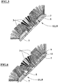
Figures 1-3 show respectively front, rear and sectional schematic views according to plane III-III offigure 2 of the device for cleaning wheels of vehicles, object of the present invention, in a condition of maximum proximity to its centre of its four supporting elements; -
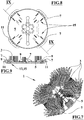
Figures 4-7 show front, rear, sectional schematic views according to plane VI-VI offigure 5 and axonometric of the device in a condition of maximum distance at its centre of its four supporting elements; -
Figures 8 shows a schematic rear view of the device offigure 1 in which the bristles of the four support elements have been removed; -
Figure 9 shows a schematic sectional view according to plane IX-IX offigure 8 ; -
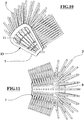
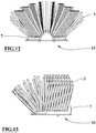
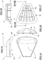
Figures 10-13 shows respectively axonometric, front and side schematic views of a support element offigure 1 ; -
Figures 14-18 show respectively front, on one side, on another side, rear and in section schematic views according to plane XVIII-XVIII of a support element offigure 1 whose bristles have been removed. - Referring to
figures 1-18 ,numeral 1 indicates the device for cleaning wheels of vehicles. This device, which has a general discoidal shape, is equipped with cleaning bristles and is assigned to be centrally connected to a horizontal rotation shaft of a vehicle wheel cleaning apparatus, e.g. in a car or vehicle washing facility in general. - Here and below, the term bristle is used to refer to a single bristle or a set or bunch of bristles made of wires or filaments of synthetic material, such as polypropylene, polyethylene or polyamide or natural material, e.g. based on vegetable fibres.
-
Reference 3 of the figures may schematically represent a single bristle consisting of a flexible filament or wire, of size, section, length, elasticity and geometric and physical characteristics in general, which may be freely chosen according to the assigned use andsuch reference 3 may schematically represent also a bunch or bundle of bristles, for example of the bent centrally type at about 180° and mutually bound in the bending portions, also in this latter case the geometrical and physical characteristics in general of the bundles or bunches of bristles and of the single bristles that constitute them can be freely chosen according to their intended use and needs. - The
bristles 3, referred therefore as single bristles or bunches or bundles of bristles, have a loose end assigned for matching with the wheel during cleaning and an opposite end, e.g. made up of the tips of the bent portions of the single bristles of the bundles or bunches of bended bristles, assigned for attachment to the remaining part ofdevice 1. - The shaft rotates axially the device which is approached and pressed against a wheel facing it for cleaning the wheel rim and eventually the outer shoulder of the corresponding tyre too.
- During the rotation of the device against the side of the wheel, the latter is expected to be sprayed with water and eventually with detergent too to obtain a thorough washing.
- The device may be used for cleaning wheels mounted on different types of land and aeronautical vehicles and for dismantled wheels, in the latter case the drive shaft of the device can be vertical.
- Said device for cleaning vehicle wheels and for washing such wheels comprises a disk shaped
element 5, centrally fitted with a coupling for the respective rotating drive shaft of the wheel-cleaning or wheel-washing apparatus or the like, foursupport elements 7 each having afastening surface 9 to whichcleaning bristles 3 are fitted or fixed and having aconnection surface 11, opposite to the fastening 9 one, having afirst connection element 13 assigned to be engaged and fixed to a respectivesecond connection element 15 of disk shapedelement 5. - This disk shaped
element 5 is preferably made of plastic material and has a thickness between one twentieth and one fifth of its external diameter. - Alternatively, it is provided that the number of
support elements 7 attached to diskshaped element 5 may be less or more than 4. - Each
second connection element 15 of the diskshaped element 5 is multiple for connecting therespective support element 7 at different distances from the centre of diskshaped element 5. In other words, thefirst connection element 13 of asupport element 7 can be connected at various distances, for example three as shown in the figures, from the centre of the disk shaped element because the correspondingsecond connection element 15 has three radially spaced connections for thefirst connection element 13. - As shown in the figures, the
first connection element 13 of eachsupport element 7 carries a triplet threaded holes for connecting screws and a pair of projecting pins and thesecond connection element 15 of disk shapedelement 5 carries, for eachsupport element 7, three triplets of spaced through holes for said screws and three pairs of concave seats for said pins where each triplet of holes and pair of seats forms a connection assembly and where these groups of holes and seats are placed at different and respective distances in the middle of the diskshaped element 5. - It is therefore possible to fix each
support element 7 to one of the three groups of triplets of holes and seats by placing it at a corresponding distance from the centre of the disk shaped element. - The number of holes and seats in each group may vary as well as the number of these groups, for example, to obtain two, four or more possible positions for each
support element 7 on the diskshaped element 5. - Alternatively, it is also provided that the
first connection element 13 of eachsupport element 7 shall have multiple sets of connections and each second connection element shall have multiple sets of connections or both first and second connection element shall have multiple sets of connections to multiply the number of possible support element positions on the diskshaped element 5. - The
bristles 3 of the device are divided into several bristle subassemblies, one for eachsupport element 7 and optionally a bristles subassembly may be attached to the disk shaped element, e.g. in the spaces between thesupport elements 7; normally the bristles of these subassemblies and of each subassembly may be the same or have different characteristics. - The bristles may be welded or glued to the
support elements 7 and eventually to the disk shaped element or preferably be restrained or otherwise fixed in recesses specially made in the elements to which they are to be fixed. For example, in the case of centrally folded bundles of bristles, the end of each bundle carrying the folds of the individual bristles shall be inserted by a tool into a recess, e.g. cylindrical and blind, made at the moment of fixing and this end is restrained in the respective recess by a restrained element, e.g. metallic, which clamps the bundle and locks it into the recess. - As an alternative to said fixing of the bristles to the support elements, device 1-7 may be fitted, for each
support element 7, with a resilient covering element, e.g. elastomeric sheet or liner, applied or fixed, for example by ultrasonic welding, to therespective fastening surface 9, where the fixing end of eachbristle 3 of therespective support element 7 is glued, welded or restrained to said covering element of thesupport element 7. - This solution makes it possible to obtain an elastic connection of the single bristles, in bundles or bunches, which protects them from excessive stress, permanent deformation and in general from damage and excessive wear.
- The
connection surface 11 of eachsupport element 7 is preferably flat and has a trapezoidal or circular crown sector shape and thecorresponding fastening surface 9 forbristles 3 is convex shaped curved or convex with concave or saddle. - This three-dimensional configuration of the
support element 7 provides much greater freedom of orientation, distribution and spacing of the bristles compared to a flat shape e.g. of the disk shaped element, in fact the number of bristles can be greater due to the larger surface area of thesupport element 7 and they can even be oriented in the opposite direction to the vehicle, e.g. for better cleaning of racing car type rims. - Each
support element 7 is solid or hollow and made of rigid or flexible synthetic material; preferably and as shown in the figures, eachsupport element 7 is rigid and hollow and the respectiveflat fastening surface 9 includes a perimeter edge and the lower sides of a set of longitudinal and transversal baffles dividing the cavity ofsupport element 7 and strengthen it. - The parts of the
first connection element 13 of eachsupport element 7, including, for example, holes and pins, are made in or placed at intersections between the lower edges of said baffles or they are placed at the respective nodes of a grid formed by said lower edges of the baffles. - The outer perimeter edge of the
connection surface 11 ofsupport element 7 is chamfered to facilitate its exit from certain wheelhouses covering part of the wheel or slightly interfering with the edge of the device. - As an alternative to the adjustable fixing of the support elements to the disk shaped element by means of screws, the invention requires that the first 13 and second 15 connection elements include radial guides and respective sliding carriages and that each
support element 7 is equipped with a respective sliding block with respect to the disk shapedelement 5. - A further alternative is that the first 13 and second 15 connection elements include radial guides and their sliding carriages and that each
support element 7 is associated to screw and nut screw, cam or similar positioning means to position thesupport element 7 with respect to the centre of the disk shapedelement 5. - The disk shaped element of the device may be equipped with holes and/or connections for water dispensers and/or detergents.
- The
bristles 3 eventually attached to the disk shaped element are preferably orthogonal to the latter and have the function of slowing the water flow away from the device by holding it in the cleaning and washing area and saving water and detergent. - The slowing down of the water flow out of the device and possibly its deviation towards the
support element 7 can be adjusted by appropriately choosing the density and length of said orthogonal bristles of the disk shaped element. - The operation of the device requires that an operator fixes all the
support elements 7 to the disk shaped element at the same distance from the centre, determined for example according to the expected dimensions of the rims and wheels, or at different distances to adapt the device to particular operating requirements; the operator then connects the device to the respective drive shaft. The disk shaped element can be equipped with several sets ofsupport elements 7 with different and/or differently distributed bristles in order to allow the operator to adapt the device to different needs without the need for several different devices saving on the cost of unnecessary disk shaped elements. - In case of breakage or wear of a
support element 7 or its bristles, the operator can easily replace it saving the cost of replacing the entire device.
Claims (9)
- Device for cleaning wheels of vehicles comprising a set of bristles (3) and a disk shaped element (5) fixable at its centre to a rotating shaft of a cleaning or washing machine for wheels or the like; said device comprises at least a support element (7) to a fastening surface (9) thereof are stuck or fixed the bristles of at least a subset of said bristles (3) and having a connection surface (11), opposed to the fastening surface (9), having a first connection element (13) assigned to be fixed to a second connection element (15) of the disk shaped element (5); said device being characterized in that at least one of said connection elements first (13) and second (15) is multiple for fixing the at least a support element (7) at different distances from the centre of the disk shaped element (5) and in that each support element (7) is solid or hollow and it is made of synthetic rigid or flexible material and the respective connection (11) and fastening (9) surfaces are respectively flat and convex or convex and concave curved.
- Device according to claim 1 characterized in that the set of bristles (3) is divided in several subsets of bristles were the bristles (3) of each subset are fixed to a respective support element (7) or the bristles (3) of one or more subsets of bristles are fixed to respective support elements (7) and the remaining bristles are fixed to the disk shaped element (5).
- Device according to claim 1 characterized in that comprises four support elements (7), the connection surfaces (11) thereof have a trapezoid or portion of annulus plan shape and the respective ends of the bristles of the four respective subsets of bristles (3) are stuck or fixed to the fastening surfaces (9) of said four support elements (7).
- Device according to any of the preceding claims characterized in that the first connection element first (13) of each support element (7) has a set of threaded holes for connection screws and a set di protruding pins and the second connection element (15) of the disk shaped element (5) has, for each of the support elements (7), two or more sets of pass through holes for said screw and two or more sets of concave sites for said pins where said sets holes and of sites are located at different and respective distances from the centre of the disk shaped element (5).
- Device according to any of the claims 1 - 3 characterized in that the connection elements first (13) and second (15) comprise radial guides and respective sliding carriages for the support elements (7) and each of the latters (7) is provided with a respective block of the sliding in respect to the disk shaped element (5).
- Device according to any of the claims 1 - 3 characterized in that the connection elements first (13) and second (15) comprise radial guides and respective sliding carriages for the support elements (7), each of the latters (7) is associated to positioning means of the screw and thread kind or of the cams kind or the like, for positioning the support elements (7) in respect to the centre of the disk shaped element (5).
- Device according to any of the preceding claims characterized in that an end of each bristle (3) is tongued, stuck, glued or welded to the respective support element (7) in correspondence of it fastening surface (9).
- Device according to any of the claims 1 - 6 characterized in that it comprises, for each support element (7), a coating element made of resilient material and stuck or fixed to the respective fastening surface (9), where the end of each bristle (3) of the respective support element (7) is glued, welded or fixed to said coating element of the support element (7).
- Device according to any of the preceding claims characterized in that the flat connection surface (11) of each support element (7) comprises a perimetric rim and the lower sides of a set of longitudinal and transversal baffles; the components of the first connection element (13), such as holes and pins, are carried out or located at crosses among said lower sides of the baffles.
Applications Claiming Priority (1)
| Application Number | Priority Date | Filing Date | Title |
|---|---|---|---|
| IT102019000000971A IT201900000971A1 (en) | 2019-01-22 | 2019-01-22 | DEVICE FOR CLEANING VEHICLE WHEELS |
Publications (2)
| Publication Number | Publication Date |
|---|---|
| EP3685703A1 true EP3685703A1 (en) | 2020-07-29 |
| EP3685703B1 EP3685703B1 (en) | 2021-10-13 |
Family
ID=66286672
Family Applications (1)
| Application Number | Title | Priority Date | Filing Date |
|---|---|---|---|
| EP20152980.7A Active EP3685703B1 (en) | 2019-01-22 | 2020-01-21 | Device for cleaning wheels of vehicles |
Country Status (3)
| Country | Link |
|---|---|
| EP (1) | EP3685703B1 (en) |
| ES (1) | ES2905598T3 (en) |
| IT (1) | IT201900000971A1 (en) |
Citations (5)
| Publication number | Priority date | Publication date | Assignee | Title |
|---|---|---|---|---|
| GB1449247A (en) | 1973-01-04 | 1976-09-15 | Fmc Corp | Rotary brush |
| US4615064A (en) | 1983-08-08 | 1986-10-07 | Pierre L. M. Alvin | Lateral street cleaning brush |
| US6457202B1 (en) | 1998-05-11 | 2002-10-01 | Randolph Torres | Sweeping machine brush mounting assembly |
| EP3231322A1 (en) | 2016-04-11 | 2017-10-18 | Weber Bürstensysteme GmbH | Segments to be mounted on and forming a circular broom |
| US20170311708A1 (en) | 2016-04-29 | 2017-11-02 | Balais Nomad Inc. | Broom Attachment, Broom Assembly and Method for Use Thereof |
-
2019
- 2019-01-22 IT IT102019000000971A patent/IT201900000971A1/en unknown
-
2020
- 2020-01-21 EP EP20152980.7A patent/EP3685703B1/en active Active
- 2020-01-21 ES ES20152980T patent/ES2905598T3/en active Active
Patent Citations (5)
| Publication number | Priority date | Publication date | Assignee | Title |
|---|---|---|---|---|
| GB1449247A (en) | 1973-01-04 | 1976-09-15 | Fmc Corp | Rotary brush |
| US4615064A (en) | 1983-08-08 | 1986-10-07 | Pierre L. M. Alvin | Lateral street cleaning brush |
| US6457202B1 (en) | 1998-05-11 | 2002-10-01 | Randolph Torres | Sweeping machine brush mounting assembly |
| EP3231322A1 (en) | 2016-04-11 | 2017-10-18 | Weber Bürstensysteme GmbH | Segments to be mounted on and forming a circular broom |
| US20170311708A1 (en) | 2016-04-29 | 2017-11-02 | Balais Nomad Inc. | Broom Attachment, Broom Assembly and Method for Use Thereof |
Also Published As
| Publication number | Publication date |
|---|---|
| IT201900000971A1 (en) | 2020-07-22 |
| ES2905598T3 (en) | 2022-04-11 |
| EP3685703B1 (en) | 2021-10-13 |
Similar Documents
| Publication | Publication Date | Title |
|---|---|---|
| US5016311A (en) | Apparatus and brush segment arrangement for finishing wheel brushes; and method | |
| US5438728A (en) | Rotary brush with segmented fiber sections | |
| CN105555167B (en) | Rotation brush for motor vehicle washing system | |
| US5784748A (en) | Vehicle laundry implement and replaceable cloth elements for use therewith | |
| US2984053A (en) | Brush and brush material | |
| US3869833A (en) | Rotary finishing wheel | |
| US6035482A (en) | Vehicle laundry implement and replaceable cloth elements for use therewith | |
| WO2006034815A2 (en) | Tool for cleaning surfaces | |
| EP3685703B1 (en) | Device for cleaning wheels of vehicles | |
| EP2714334B1 (en) | Grinding head | |
| EP1213984B1 (en) | Washing device for a car wash unit | |
| CZ293294B6 (en) | Brush ring | |
| US9950408B2 (en) | Abrasive pad | |
| US10549728B1 (en) | Reverse rotation side washer for vehicles including a shaft assembly and retrofit discs | |
| US6289544B1 (en) | Vehicle washing apparatus | |
| US4835913A (en) | Deburring apparatus | |
| EP0639419B1 (en) | A rasp hub assembly | |
| EP0339933B1 (en) | Apparatus and brush segment arrangement for finishing wheel brushes, and method | |
| US11096478B2 (en) | Device for filament end-rounding and a method for end-rounding toothbrush filaments | |
| KR20120064005A (en) | brush | |
| EP0245578B1 (en) | A rotary brush structure for a motor vehicle washing installation | |
| US3914908A (en) | Rotary finishing wheel | |
| JP2009108632A (en) | Rotating brush for road sweeper and road sweeper | |
| US7195553B2 (en) | Grinding module | |
| EP4205600B1 (en) | Brush for cleaning surfaces |
Legal Events
| Date | Code | Title | Description |
|---|---|---|---|
| PUAI | Public reference made under article 153(3) epc to a published international application that has entered the european phase |
Free format text: ORIGINAL CODE: 0009012 |
|
| STAA | Information on the status of an ep patent application or granted ep patent |
Free format text: STATUS: THE APPLICATION HAS BEEN PUBLISHED |
|
| AK | Designated contracting states |
Kind code of ref document: A1 Designated state(s): AL AT BE BG CH CY CZ DE DK EE ES FI FR GB GR HR HU IE IS IT LI LT LU LV MC MK MT NL NO PL PT RO RS SE SI SK SM TR |
|
| AX | Request for extension of the european patent |
Extension state: BA ME |
|
| STAA | Information on the status of an ep patent application or granted ep patent |
Free format text: STATUS: REQUEST FOR EXAMINATION WAS MADE |
|
| 17P | Request for examination filed |
Effective date: 20210117 |
|
| RBV | Designated contracting states (corrected) |
Designated state(s): AL AT BE BG CH CY CZ DE DK EE ES FI FR GB GR HR HU IE IS IT LI LT LU LV MC MK MT NL NO PL PT RO RS SE SI SK SM TR |
|
| GRAP | Despatch of communication of intention to grant a patent |
Free format text: ORIGINAL CODE: EPIDOSNIGR1 |
|
| STAA | Information on the status of an ep patent application or granted ep patent |
Free format text: STATUS: GRANT OF PATENT IS INTENDED |
|
| INTG | Intention to grant announced |
Effective date: 20210519 |
|
| GRAS | Grant fee paid |
Free format text: ORIGINAL CODE: EPIDOSNIGR3 |
|
| GRAA | (expected) grant |
Free format text: ORIGINAL CODE: 0009210 |
|
| STAA | Information on the status of an ep patent application or granted ep patent |
Free format text: STATUS: THE PATENT HAS BEEN GRANTED |
|
| AK | Designated contracting states |
Kind code of ref document: B1 Designated state(s): AL AT BE BG CH CY CZ DE DK EE ES FI FR GB GR HR HU IE IS IT LI LT LU LV MC MK MT NL NO PL PT RO RS SE SI SK SM TR |
|
| REG | Reference to a national code |
Ref country code: GB Ref legal event code: FG4D |
|
| REG | Reference to a national code |
Ref country code: CH Ref legal event code: EP |
|
| REG | Reference to a national code |
Ref country code: DE Ref legal event code: R096 Ref document number: 602020000697 Country of ref document: DE |
|
| REG | Reference to a national code |
Ref country code: IE Ref legal event code: FG4D |
|
| REG | Reference to a national code |
Ref country code: AT Ref legal event code: REF Ref document number: 1437483 Country of ref document: AT Kind code of ref document: T Effective date: 20211115 |
|
| REG | Reference to a national code |
Ref country code: LT Ref legal event code: MG9D |
|
| REG | Reference to a national code |
Ref country code: NL Ref legal event code: MP Effective date: 20211013 |
|
| REG | Reference to a national code |
Ref country code: AT Ref legal event code: MK05 Ref document number: 1437483 Country of ref document: AT Kind code of ref document: T Effective date: 20211013 |
|
| REG | Reference to a national code |
Ref country code: ES Ref legal event code: FG2A Ref document number: 2905598 Country of ref document: ES Kind code of ref document: T3 Effective date: 20220411 |
|
| PG25 | Lapsed in a contracting state [announced via postgrant information from national office to epo] |
Ref country code: RS Free format text: LAPSE BECAUSE OF FAILURE TO SUBMIT A TRANSLATION OF THE DESCRIPTION OR TO PAY THE FEE WITHIN THE PRESCRIBED TIME-LIMIT Effective date: 20211013 Ref country code: LT Free format text: LAPSE BECAUSE OF FAILURE TO SUBMIT A TRANSLATION OF THE DESCRIPTION OR TO PAY THE FEE WITHIN THE PRESCRIBED TIME-LIMIT Effective date: 20211013 Ref country code: FI Free format text: LAPSE BECAUSE OF FAILURE TO SUBMIT A TRANSLATION OF THE DESCRIPTION OR TO PAY THE FEE WITHIN THE PRESCRIBED TIME-LIMIT Effective date: 20211013 Ref country code: BG Free format text: LAPSE BECAUSE OF FAILURE TO SUBMIT A TRANSLATION OF THE DESCRIPTION OR TO PAY THE FEE WITHIN THE PRESCRIBED TIME-LIMIT Effective date: 20220113 Ref country code: AT Free format text: LAPSE BECAUSE OF FAILURE TO SUBMIT A TRANSLATION OF THE DESCRIPTION OR TO PAY THE FEE WITHIN THE PRESCRIBED TIME-LIMIT Effective date: 20211013 |
|
| PG25 | Lapsed in a contracting state [announced via postgrant information from national office to epo] |
Ref country code: IS Free format text: LAPSE BECAUSE OF FAILURE TO SUBMIT A TRANSLATION OF THE DESCRIPTION OR TO PAY THE FEE WITHIN THE PRESCRIBED TIME-LIMIT Effective date: 20220213 Ref country code: SE Free format text: LAPSE BECAUSE OF FAILURE TO SUBMIT A TRANSLATION OF THE DESCRIPTION OR TO PAY THE FEE WITHIN THE PRESCRIBED TIME-LIMIT Effective date: 20211013 Ref country code: PT Free format text: LAPSE BECAUSE OF FAILURE TO SUBMIT A TRANSLATION OF THE DESCRIPTION OR TO PAY THE FEE WITHIN THE PRESCRIBED TIME-LIMIT Effective date: 20220214 Ref country code: PL Free format text: LAPSE BECAUSE OF FAILURE TO SUBMIT A TRANSLATION OF THE DESCRIPTION OR TO PAY THE FEE WITHIN THE PRESCRIBED TIME-LIMIT Effective date: 20211013 Ref country code: NO Free format text: LAPSE BECAUSE OF FAILURE TO SUBMIT A TRANSLATION OF THE DESCRIPTION OR TO PAY THE FEE WITHIN THE PRESCRIBED TIME-LIMIT Effective date: 20220113 Ref country code: NL Free format text: LAPSE BECAUSE OF FAILURE TO SUBMIT A TRANSLATION OF THE DESCRIPTION OR TO PAY THE FEE WITHIN THE PRESCRIBED TIME-LIMIT Effective date: 20211013 Ref country code: LV Free format text: LAPSE BECAUSE OF FAILURE TO SUBMIT A TRANSLATION OF THE DESCRIPTION OR TO PAY THE FEE WITHIN THE PRESCRIBED TIME-LIMIT Effective date: 20211013 Ref country code: HR Free format text: LAPSE BECAUSE OF FAILURE TO SUBMIT A TRANSLATION OF THE DESCRIPTION OR TO PAY THE FEE WITHIN THE PRESCRIBED TIME-LIMIT Effective date: 20211013 Ref country code: GR Free format text: LAPSE BECAUSE OF FAILURE TO SUBMIT A TRANSLATION OF THE DESCRIPTION OR TO PAY THE FEE WITHIN THE PRESCRIBED TIME-LIMIT Effective date: 20220114 |
|
| REG | Reference to a national code |
Ref country code: DE Ref legal event code: R097 Ref document number: 602020000697 Country of ref document: DE |
|
| PG25 | Lapsed in a contracting state [announced via postgrant information from national office to epo] |
Ref country code: SM Free format text: LAPSE BECAUSE OF FAILURE TO SUBMIT A TRANSLATION OF THE DESCRIPTION OR TO PAY THE FEE WITHIN THE PRESCRIBED TIME-LIMIT Effective date: 20211013 Ref country code: SK Free format text: LAPSE BECAUSE OF FAILURE TO SUBMIT A TRANSLATION OF THE DESCRIPTION OR TO PAY THE FEE WITHIN THE PRESCRIBED TIME-LIMIT Effective date: 20211013 Ref country code: RO Free format text: LAPSE BECAUSE OF FAILURE TO SUBMIT A TRANSLATION OF THE DESCRIPTION OR TO PAY THE FEE WITHIN THE PRESCRIBED TIME-LIMIT Effective date: 20211013 Ref country code: EE Free format text: LAPSE BECAUSE OF FAILURE TO SUBMIT A TRANSLATION OF THE DESCRIPTION OR TO PAY THE FEE WITHIN THE PRESCRIBED TIME-LIMIT Effective date: 20211013 Ref country code: DK Free format text: LAPSE BECAUSE OF FAILURE TO SUBMIT A TRANSLATION OF THE DESCRIPTION OR TO PAY THE FEE WITHIN THE PRESCRIBED TIME-LIMIT Effective date: 20211013 Ref country code: CZ Free format text: LAPSE BECAUSE OF FAILURE TO SUBMIT A TRANSLATION OF THE DESCRIPTION OR TO PAY THE FEE WITHIN THE PRESCRIBED TIME-LIMIT Effective date: 20211013 |
|
| PLBE | No opposition filed within time limit |
Free format text: ORIGINAL CODE: 0009261 |
|
| STAA | Information on the status of an ep patent application or granted ep patent |
Free format text: STATUS: NO OPPOSITION FILED WITHIN TIME LIMIT |
|
| PG25 | Lapsed in a contracting state [announced via postgrant information from national office to epo] |
Ref country code: MC Free format text: LAPSE BECAUSE OF FAILURE TO SUBMIT A TRANSLATION OF THE DESCRIPTION OR TO PAY THE FEE WITHIN THE PRESCRIBED TIME-LIMIT Effective date: 20211013 |
|
| 26N | No opposition filed |
Effective date: 20220714 |
|
| REG | Reference to a national code |
Ref country code: BE Ref legal event code: MM Effective date: 20220131 |
|
| PG25 | Lapsed in a contracting state [announced via postgrant information from national office to epo] |
Ref country code: LU Free format text: LAPSE BECAUSE OF NON-PAYMENT OF DUE FEES Effective date: 20220121 Ref country code: AL Free format text: LAPSE BECAUSE OF FAILURE TO SUBMIT A TRANSLATION OF THE DESCRIPTION OR TO PAY THE FEE WITHIN THE PRESCRIBED TIME-LIMIT Effective date: 20211013 |
|
| PG25 | Lapsed in a contracting state [announced via postgrant information from national office to epo] |
Ref country code: SI Free format text: LAPSE BECAUSE OF FAILURE TO SUBMIT A TRANSLATION OF THE DESCRIPTION OR TO PAY THE FEE WITHIN THE PRESCRIBED TIME-LIMIT Effective date: 20211013 Ref country code: BE Free format text: LAPSE BECAUSE OF NON-PAYMENT OF DUE FEES Effective date: 20220131 |
|
| PG25 | Lapsed in a contracting state [announced via postgrant information from national office to epo] |
Ref country code: IE Free format text: LAPSE BECAUSE OF NON-PAYMENT OF DUE FEES Effective date: 20220121 |
|
| PG25 | Lapsed in a contracting state [announced via postgrant information from national office to epo] |
Ref country code: IT Free format text: LAPSE BECAUSE OF FAILURE TO SUBMIT A TRANSLATION OF THE DESCRIPTION OR TO PAY THE FEE WITHIN THE PRESCRIBED TIME-LIMIT Effective date: 20211013 |
|
| REG | Reference to a national code |
Ref country code: CH Ref legal event code: PL |
|
| PG25 | Lapsed in a contracting state [announced via postgrant information from national office to epo] |
Ref country code: LI Free format text: LAPSE BECAUSE OF NON-PAYMENT OF DUE FEES Effective date: 20230131 Ref country code: CH Free format text: LAPSE BECAUSE OF NON-PAYMENT OF DUE FEES Effective date: 20230131 |
|
| PG25 | Lapsed in a contracting state [announced via postgrant information from national office to epo] |
Ref country code: MK Free format text: LAPSE BECAUSE OF FAILURE TO SUBMIT A TRANSLATION OF THE DESCRIPTION OR TO PAY THE FEE WITHIN THE PRESCRIBED TIME-LIMIT Effective date: 20211013 Ref country code: CY Free format text: LAPSE BECAUSE OF FAILURE TO SUBMIT A TRANSLATION OF THE DESCRIPTION OR TO PAY THE FEE WITHIN THE PRESCRIBED TIME-LIMIT Effective date: 20211013 |
|
| PG25 | Lapsed in a contracting state [announced via postgrant information from national office to epo] |
Ref country code: HU Free format text: LAPSE BECAUSE OF FAILURE TO SUBMIT A TRANSLATION OF THE DESCRIPTION OR TO PAY THE FEE WITHIN THE PRESCRIBED TIME-LIMIT; INVALID AB INITIO Effective date: 20200121 |
|
| GBPC | Gb: european patent ceased through non-payment of renewal fee |
Effective date: 20240121 |
|
| PG25 | Lapsed in a contracting state [announced via postgrant information from national office to epo] |
Ref country code: MT Free format text: LAPSE BECAUSE OF FAILURE TO SUBMIT A TRANSLATION OF THE DESCRIPTION OR TO PAY THE FEE WITHIN THE PRESCRIBED TIME-LIMIT Effective date: 20211013 |
|
| PG25 | Lapsed in a contracting state [announced via postgrant information from national office to epo] |
Ref country code: GB Free format text: LAPSE BECAUSE OF NON-PAYMENT OF DUE FEES Effective date: 20240121 |
|
| PG25 | Lapsed in a contracting state [announced via postgrant information from national office to epo] |
Ref country code: GB Free format text: LAPSE BECAUSE OF NON-PAYMENT OF DUE FEES Effective date: 20240121 |
|
| PG25 | Lapsed in a contracting state [announced via postgrant information from national office to epo] |
Ref country code: TR Free format text: LAPSE BECAUSE OF FAILURE TO SUBMIT A TRANSLATION OF THE DESCRIPTION OR TO PAY THE FEE WITHIN THE PRESCRIBED TIME-LIMIT Effective date: 20211013 |
|
| PGFP | Annual fee paid to national office [announced via postgrant information from national office to epo] |
Ref country code: ES Payment date: 20260210 Year of fee payment: 7 |
|
| PGFP | Annual fee paid to national office [announced via postgrant information from national office to epo] |
Ref country code: DE Payment date: 20260127 Year of fee payment: 7 |
|
| PGFP | Annual fee paid to national office [announced via postgrant information from national office to epo] |
Ref country code: FR Payment date: 20260126 Year of fee payment: 7 |