EP3685541B1 - Brouillage csi-rs de sous-trames dans une drs à sous-trames multiples - Google Patents
Brouillage csi-rs de sous-trames dans une drs à sous-trames multiples Download PDFInfo
- Publication number
- EP3685541B1 EP3685541B1 EP18789288.0A EP18789288A EP3685541B1 EP 3685541 B1 EP3685541 B1 EP 3685541B1 EP 18789288 A EP18789288 A EP 18789288A EP 3685541 B1 EP3685541 B1 EP 3685541B1
- Authority
- EP
- European Patent Office
- Prior art keywords
- drs
- block
- subframes
- subframe
- csi
- Prior art date
- Legal status (The legal status is an assumption and is not a legal conclusion. Google has not performed a legal analysis and makes no representation as to the accuracy of the status listed.)
- Active
Links
- 238000004891 communication Methods 0.000 claims description 65
- 238000000034 method Methods 0.000 claims description 44
- 230000005540 biological transmission Effects 0.000 claims description 30
- 230000011664 signaling Effects 0.000 claims description 17
- 238000005259 measurement Methods 0.000 claims description 9
- 238000012544 monitoring process Methods 0.000 claims description 6
- 108091006146 Channels Proteins 0.000 description 34
- 230000008569 process Effects 0.000 description 19
- 230000015654 memory Effects 0.000 description 16
- 238000013461 design Methods 0.000 description 15
- 238000005516 engineering process Methods 0.000 description 12
- 238000001228 spectrum Methods 0.000 description 11
- 101100392078 Caenorhabditis elegans cat-4 gene Proteins 0.000 description 8
- 238000010586 diagram Methods 0.000 description 8
- 239000000969 carrier Substances 0.000 description 7
- 238000001514 detection method Methods 0.000 description 6
- 230000009471 action Effects 0.000 description 4
- 201000000913 Duane retraction syndrome Diseases 0.000 description 3
- 238000000162 direct recoil spectroscopy Methods 0.000 description 3
- 230000000694 effects Effects 0.000 description 3
- 230000002452 interceptive effect Effects 0.000 description 3
- 230000007774 longterm Effects 0.000 description 3
- 201000003042 peeling skin syndrome Diseases 0.000 description 3
- 229920001467 poly(styrenesulfonates) Polymers 0.000 description 3
- 230000001934 delay Effects 0.000 description 2
- 238000007667 floating Methods 0.000 description 2
- 239000002245 particle Substances 0.000 description 2
- 239000013589 supplement Substances 0.000 description 2
- 230000006978 adaptation Effects 0.000 description 1
- 230000001413 cellular effect Effects 0.000 description 1
- 125000004122 cyclic group Chemical group 0.000 description 1
- 230000003111 delayed effect Effects 0.000 description 1
- 230000006870 function Effects 0.000 description 1
- 230000002045 lasting effect Effects 0.000 description 1
- 238000004519 manufacturing process Methods 0.000 description 1
- 230000007246 mechanism Effects 0.000 description 1
- 238000012986 modification Methods 0.000 description 1
- 230000004048 modification Effects 0.000 description 1
- 230000003287 optical effect Effects 0.000 description 1
- 230000000737 periodic effect Effects 0.000 description 1
- 230000003595 spectral effect Effects 0.000 description 1
Images


Classifications
-
- H—ELECTRICITY
- H04—ELECTRIC COMMUNICATION TECHNIQUE
- H04W—WIRELESS COMMUNICATION NETWORKS
- H04W72/00—Local resource management
- H04W72/12—Wireless traffic scheduling
- H04W72/1215—Wireless traffic scheduling for collaboration of different radio technologies
-
- H—ELECTRICITY
- H04—ELECTRIC COMMUNICATION TECHNIQUE
- H04L—TRANSMISSION OF DIGITAL INFORMATION, e.g. TELEGRAPHIC COMMUNICATION
- H04L25/00—Baseband systems
- H04L25/02—Details ; arrangements for supplying electrical power along data transmission lines
- H04L25/03—Shaping networks in transmitter or receiver, e.g. adaptive shaping networks
- H04L25/03828—Arrangements for spectral shaping; Arrangements for providing signals with specified spectral properties
- H04L25/03866—Arrangements for spectral shaping; Arrangements for providing signals with specified spectral properties using scrambling
-
- H—ELECTRICITY
- H04—ELECTRIC COMMUNICATION TECHNIQUE
- H04L—TRANSMISSION OF DIGITAL INFORMATION, e.g. TELEGRAPHIC COMMUNICATION
- H04L27/00—Modulated-carrier systems
- H04L27/0006—Assessment of spectral gaps suitable for allocating digitally modulated signals, e.g. for carrier allocation in cognitive radio
-
- H—ELECTRICITY
- H04—ELECTRIC COMMUNICATION TECHNIQUE
- H04L—TRANSMISSION OF DIGITAL INFORMATION, e.g. TELEGRAPHIC COMMUNICATION
- H04L5/00—Arrangements affording multiple use of the transmission path
- H04L5/003—Arrangements for allocating sub-channels of the transmission path
- H04L5/0048—Allocation of pilot signals, i.e. of signals known to the receiver
- H04L5/005—Allocation of pilot signals, i.e. of signals known to the receiver of common pilots, i.e. pilots destined for multiple users or terminals
-
- H—ELECTRICITY
- H04—ELECTRIC COMMUNICATION TECHNIQUE
- H04L—TRANSMISSION OF DIGITAL INFORMATION, e.g. TELEGRAPHIC COMMUNICATION
- H04L5/00—Arrangements affording multiple use of the transmission path
- H04L5/0091—Signaling for the administration of the divided path
- H04L5/0094—Indication of how sub-channels of the path are allocated
-
- H—ELECTRICITY
- H04—ELECTRIC COMMUNICATION TECHNIQUE
- H04L—TRANSMISSION OF DIGITAL INFORMATION, e.g. TELEGRAPHIC COMMUNICATION
- H04L5/00—Arrangements affording multiple use of the transmission path
- H04L5/0001—Arrangements for dividing the transmission path
- H04L5/0003—Two-dimensional division
- H04L5/0005—Time-frequency
- H04L5/0007—Time-frequency the frequencies being orthogonal, e.g. OFDM(A), DMT
- H04L5/001—Time-frequency the frequencies being orthogonal, e.g. OFDM(A), DMT the frequencies being arranged in component carriers
-
- H—ELECTRICITY
- H04—ELECTRIC COMMUNICATION TECHNIQUE
- H04W—WIRELESS COMMUNICATION NETWORKS
- H04W16/00—Network planning, e.g. coverage or traffic planning tools; Network deployment, e.g. resource partitioning or cells structures
- H04W16/14—Spectrum sharing arrangements between different networks
-
- H—ELECTRICITY
- H04—ELECTRIC COMMUNICATION TECHNIQUE
- H04W—WIRELESS COMMUNICATION NETWORKS
- H04W72/00—Local resource management
- H04W72/50—Allocation or scheduling criteria for wireless resources
- H04W72/54—Allocation or scheduling criteria for wireless resources based on quality criteria
-
- H—ELECTRICITY
- H04—ELECTRIC COMMUNICATION TECHNIQUE
- H04W—WIRELESS COMMUNICATION NETWORKS
- H04W74/00—Wireless channel access
- H04W74/08—Non-scheduled access, e.g. ALOHA
- H04W74/0808—Non-scheduled access, e.g. ALOHA using carrier sensing, e.g. carrier sense multiple access [CSMA]
Definitions
- aspects of this disclosure relate generally to telecommunications, and more particularly to operations on a shared communication medium and the like.
- Wireless communication systems are widely deployed to provide various types of communication content, such as voice, data, multimedia, and so on.
- Typical wireless communication systems are multiple-access systems capable of supporting communication with multiple users by sharing available system resources (e.g., bandwidth, transmit power, etc.).
- Examples of such multiple-access systems include Code Division Multiple Access (CDMA) systems, Time Division Multiple Access (TDMA) systems, Frequency Division Multiple Access (FDMA) systems, Orthogonal Frequency Division Multiple Access (OFDMA) systems, and others.
- CDMA Code Division Multiple Access
- TDMA Time Division Multiple Access
- FDMA Frequency Division Multiple Access
- OFDMA Orthogonal Frequency Division Multiple Access
- LTE Long Term Evolution
- UMB Ultra Mobile Broadband
- EV-DO Evolution Data Optimized
- 3GPP2 Third Generation Partnership Project 2
- IEEE Institute of Electrical and Electronics Engineers
- macro cell access points provide connectivity and coverage to a large number of users over a certain geographical area.
- a macro network deployment is carefully planned, designed, and implemented to offer good coverage over the geographical region.
- additional "small cell,” typically low-power access points have recently begun to be deployed to supplement conventional macro networks.
- Small cell access points may also provide incremental capacity growth, richer user experience, and so on.
- Small cell LTE operations have been extended into the unlicensed frequency spectrum such as the Unlicensed National Information Infrastructure (U-NII) band used by Wireless Local Area Network (WLAN) technologies.
- U-NII Unlicensed National Information Infrastructure
- WLAN Wireless Local Area Network
- This extension of small cell LTE operation is designed to increase spectral efficiency and hence capacity of the LTE system.
- RATs Radio Access Technologies
- Wi-Fi IEEE 802.11x WLAN technologies generally referred to as "Wi-Fi.”
- US 2017/0134148 relates to detecting and descrambling a DRS by a UE using licensed-assisted access for accessing resources in an unlicensed spectrum, and using the detected and descrambled DRS to perform neighbor cell measurements for processes such as cell selection for the unlicensed spectrum.
- US2017/0164247 relates to a network node is arranged to transmit a discovery reference signal (DRS) comprising a first and a second synchronization signal for enabling wireless devices to find and measure the cell.
- DRS discovery reference signal
- CSI-RSs channel state information reference signals
- CSI-RSs channel state information reference signals
- an access point for configuring channel state information reference signals (CSI-RSs) on a shared communication medium as set out in claim 12.
- CSI-RSs channel state information reference signals
- a user equipment configured to obtain channel state information reference signals (CSI-RSs) on a shared communication medium as set out in claim 13.
- CSI-RSs channel state information reference signals
- the radio link may be a Long-Term Evolution (LTE) in unlicensed spectrum radio link.
- LTE Long-Term Evolution
- FIG. 1 is a system-level diagram illustrating an example wireless network environment, shown by way of example as including a "primary" Radio Access Technology (RAT) system 100 and a "competing" RAT system 150.
- RAT Radio Access Technology
- Each system may be composed of different wireless nodes generally capable of receiving and/or transmitting over a radio link, including information related to various types of communication (e.g., voice, data, multimedia services, associated control signaling, etc.).
- the primary RAT system 100 is shown as including an access point 110 and an access terminal 120 in communication with each other over a radio link 130.
- the competing RAT system 150 is shown as including two competing nodes 152 in communication with each other over a separate radio link 132, and may similarly include one or more access points, access terminals, or other types of wireless nodes.
- the access point 110 and the access terminal 120 of the primary RAT system 100 may communicate via the radio link 130 in accordance with Long Term Evolution (LTE) technology, while the competing nodes 152 of the competing RAT system 150 may communicate via the radio link 132 in accordance with Wi-Fi technology.
- LTE Long Term Evolution
- Wi-Fi Wireless Fidelity
- access terminal and “access point” are not intended to be specific or limited to any particular RAT.
- access terminals may be any wireless communication device allowing a user to communicate over a communications network (e.g., a mobile phone, router, personal computer, server, entertainment device, Internet of Things (IOT) / Internet of Everything (TOE) capable device, in-vehicle communication device, etc.), and may be alternatively referred to in different RAT environments as a User Device (UD), a Mobile Station (MS), a Subscriber Station (STA), a User Equipment (UE), etc.
- UD User Device
- MS Mobile Station
- STA Subscriber Station
- UE User Equipment
- an access point may operate according to one or several RATs in communicating with access terminals depending on the network in which the access point is deployed, and may be alternatively referred to as a Base Station (BS), a Network Node, a NodeB, an evolved NodeB (eNB), etc.
- BS Base Station
- eNB evolved NodeB
- Such an access point may correspond to a small cell access point, for example.
- Small cells generally refer to a class of low-powered access points that may include or be otherwise referred to as femto cells, pico cells, micro cells, Wireless Local Area Network (WLAN) access points, other small coverage area access points, etc. Small cells may be deployed to supplement macro cell coverage, which may cover a few blocks within a neighborhood or several square miles in a rural environment, thereby leading to improved signaling, incremental capacity growth, richer user experience, and so on.
- the radio link 130 used by the primary RAT system 100 and the radio link 132 used by the competing RAT system 150 may operate over a shared communication medium 140.
- a communication medium of this type may be composed of one or more frequency, time, and/or space communication resources (e.g., encompassing one or more channels across one or more carriers).
- the communication medium 140 may correspond to at least a portion of an unlicensed frequency band.
- U-NII Unlicensed National Information Infrastructure
- CCA Clear Channel Assessment
- ETSI European Telecommunications Standards Institute
- the access point 110 may include a DRS scheduler 121 and the access terminal 120 may include a DRS manager 122.
- the DRS scheduler 121 may be configured to generate and facilitate transmission of the multi-subframe DRS described below with respect to FIGS. 3A-3B
- the DRS manager 122 may be configured to facilitate decoding of the multi-subframe DRS at the access terminal 120.
- the access point 110 may include a channel state information reference signal (CSI-RS) scheduler 123.
- the CSI-RS scheduler 123 may be configured to generate and facilitate transmission of the multi-subframe DRS described below with respect to FIGS. 3A-3B , with CSI-RS(s) being scrambled as described below with respect to FIGS. 6-7 .
- FIG. 2 illustrates an example frame structure that may be implemented for the primary RAT system 100 on the communication medium 140 to facilitate contention-based access to the communication medium 140.
- the illustrated frame structure includes a series of radio frames (RFs) that are numbered in accordance with a system frame number numerology (RF N , RF N+1 , RF N+2 , etc.) and divided into respective subframes (SFs), which may also be numbered for reference (e.g., SF0, SF1, etc.).
- RF N system frame number numerology
- SFs subframes
- Each respective subframe may be further divided into slots (not shown in FIG. 2 ), and the slots may be further divided into symbol periods.
- the LTE frame structure includes system frames that are divided into 1024 numbered radio frames composed of 10 subframes each, which together constitute a system frame cycle (e.g., lasting 10.24s for 10ms radio frames having 1ms subframes).
- each subframe may comprise two slots, and each slot may comprise six or seven symbol periods.
- the use of a frame structure may provide more natural and efficient coordination among devices than more ad hoc signaling techniques.
- the example frame structure of FIG. 2 may be implemented as a Frequency Division Duplex (FDD) frame structure or a Time Division Duplex (TDD) frame structure.
- FDD Frequency Division Duplex
- TDD Time Division Duplex
- each subframe on a given frequency may be statically configured for uplink (UL) communication for transmitting uplink information from the access terminal 120 to the access point 110 or for downlink (DL) communication for transmitting downlink information from the access point 110 to the access terminal 120.
- UL uplink
- DL downlink
- each subframe may be variously operated at different times as a downlink (D), uplink (U), or special (S) subframe. Different arrangements of downlink, uplink, and special subframes may be referred to as different TDD configurations.
- the frame structure of FIG. 2 may be "fixed" in that the location of each subframe may be predetermined in relation to an absolute time, but may or may not be occupied by primary RAT signaling in any given instance due to the contention procedure for accessing the communication medium 140. For example, if the access point 110 or the access terminal 120 fail to win contention for a given subframe that subframe may be silenced.
- the frame structure of FIG. 2 may be "floating" in that the location of each subframe may be dynamically determined in relation to the point at which access to the communication medium 140 is secured. For example, the start of a given frame (e.g., RF N+1 ) may be delayed in relation to an absolute time until the access point 110 or the access terminal 120 is able to win contention.
- one or more subframes may be designated to include what is referred to herein as Discovery Reference Signaling (DRS).
- DRS may be configured to convey reference signaling for facilitating system operation.
- the reference signaling may include information relevant to timing synchronization, system acquisition, interference measurements (e.g., Radio Resource Measurements (RRM) / Radio Link Measurements (RLM)), tracking loops, gain reference (e.g., Automatic Gain Control (AGC)), paging, etc.
- RRM Radio Resource Measurements
- RLM Radio Link Measurements
- AGC Automatic Gain Control
- the DRS may include a Primary Synchronization Signal (PSS) and a Secondary Synchronization Signal (SSS) for cell searching, a Cell-specific Reference Signal (CRS) for RRM, a Physical Broadcast Channel (PBCH) for conveying various access parameters, and so on.
- PSS Primary Synchronization Signal
- SSS Secondary Synchronization Signal
- CRS Cell-specific Reference Signal
- PBCH Physical Broadcast Channel
- the DRS may be scheduled for transmission periodically (e.g., every 10ms) in a designated subframe(s) of each radio frame (e.g., subframe SF0) or in a range of such subframes referred to as a DRS Measurement Timing Configuration (DMTC) window defined around a designated subframe (e.g., spanning the first six subframes SFO to SF5 of the radio frame).
- DMTC DRS Measurement Timing Configuration
- the periodic DRS signals are used to monitor the quality of the radio link (e.g., radio link 130) and to trigger a Radio Link Failure (RLF) when operating conditions on the radio link deteriorate.
- RLF Radio Link Failure
- LTE in licensed spectrum has fewer CRS instances due to the relatively sparse DRS periodicity. More specifically, for LTE in licensed spectrum, CRS occurs every SF, whereas for LTE in unlicensed spectrum, DRS typically occurs every 40ms, 80ms, or 160ms.
- LTE in unlicensed spectrum has missed DRS events, which may be due to an LBT failure at the access point 110 or a CRS scrambling mismatch at the access terminal 120.
- DRS scrambling is either SFO or SF5 scrambling, depending on whether DRS is transmitted on SFO to SF4 or SF5 to SF9, respectively.
- a subframe may have subframe specific scrambling or DRS scrambling.
- the ability to monitor one or both CRS scrambling possibilities is a capability of the access terminal 120 defined by the value "mf-MonitorTwoCRSScramblings.”
- the access terminal 120 prioritizes the monitoring of signals that use subframe specific scrambling.
- FIG. 3A illustrates a multi-subframe DRS 300A in accordance with an embodiment of the disclosure.
- FIG. 3A depicts a resource map of channels to resource blocks within the multi-subframe DRS 300A.
- the multi-subframe DRS 300A may be supported by LBT Category 4 (Cat 4). As shown in FIG. 3A , the multi-subframe DRS 300A includes subframes 0...3 (referred to below as the 0 th , 1 st , 2 nd and 3 rd DRS subframes) that each include 14 symbols denoted as symbols 0...13.
- the first subframe (or 0 th DRS subframe) is a legacy MulteFire DRS subframe that is extended to 14 symbols.
- the multi-subframe DRS 300A may be configured with a different number of DRS subframes (e.g., 5, 6, etc.).
- the later subframes may be used for coverage enhancement (CE) for extended PSSs (ePSSs), extended SSSs (eSSSs), an extended PBCH (ePBCH) and extended system information block (eSIBs).
- ePSSs extended PSSs
- eSSSs extended SSSs
- ePBCH extended PBCH
- eSIBs extended system information block
- the 1 st DRS subframe may include an ePSS in each of symbols 0...14 and may be referred to as an ePSS subframe
- the 2 nd DRS subframe may include an eSSS in each of symbols 0... 14 and may be referred to as an eSSS subframe
- the 3 rd DRS subframe may include an ePBCH in each of symbols 0... 14 and may be referred to as an ePBCH subframe.
- two PSSs may be included within the multi-subframe DRS 300A for one shot acquisition at a Signal-to-Noise Ratio (SNR) of -6 dB.
- SNR Signal-to-Noise Ratio
- At least 12 or 14 ePSSs may be included to support 6 Resource Blocks (RBs) on 62 carriers.
- RBs Resource Blocks
- a different set of ePSS sequences of length 62 may be used in the 1 st DRS subframe relative to the 0 th DRS subframe (e.g., 1/3 hypothesis).
- Use length -12/14 cover code to generate 12/14 repetitions in 12/14 OFDM symbols (similar to Narrow Band (NB)-PSS).
- the eSSS may be repeated over 12/14 symbols in the 2 nd DRS subframe following the ePSS subframe (or 1 st DRS subframe).
- Each eSSS may be configured to convey 1 out of 168 cell IDs within a cell ID group (e.g., assuming 3 hypotheses in ePSS).
- the starting symbol of the 2 nd DRS subframe may be conveyed via the SSS in the 0 th DRS subframe using a different short code. The short code depends on whether the 2 nd DRS subframe is located in SF0-SF4 or SF5-SF9.
- the SSS may be configured similarly to Narrow Band SSS (NSSS) in NB-IoT by extending the number of eSSS repetitions to 12/14 symbols and 6 RBs of bandwidth.
- NSSS Narrow Band SSS
- Each eSSS conveys 1 out of 504 cell IDs (e.g., assuming 1 hypothesis in ePSS).
- FIG. 3B illustrates a multi-subframe DRS 300B in accordance with another embodiment of the disclosure.
- FIG. 3B depicts a resource map of channels to resource blocks within the multi-subframe DRS 300B.
- the multi-subframe DRS 300B may be supported by LBT Cat 4.
- the multi-subframe DRS 300B in FIG. 3B includes two (2) DRS subframes.
- FIG. 3B is described at a lower level of detail as compared to FIG. 3A to emphasize particular aspects.
- channel bandwidth 305B spans a portion of available frequencies, and OFDM symbols 0 to 13 of each DRS subframe 310B and 315B within the bandwidth 305B are labeled across the top of the allocated resources.
- the MF 1.0 PSS and the MF 1.0 SSS (which may alternatively be referred to as ePSS and eSSS, respectively) may be transported on R sub-carriers 320B centered within the bandwidth 305B.
- Each of the R sub-carriers 320B may be offset by one another in frequency (e.g., 15 kHz between each sub-carrier).
- the access point 110 may transmit the MF 1.0 PSS within a set of consecutive DRS subframes (e.g., within symbol 3 of DRS subframe 310B, within symbol 5 of DRS subframe 315B).
- the same R sub-carriers 320B may also be used to transport MF 1.0 SSS and PBCH in DRS subframes 310B and 315B.
- the access point 110 may transmit the MF 1.0 SSS within the set of consecutive DRS subframes (e.g., within symbol 2 of DRS subframe 310B, within symbol 6 of DRS subframes 315B), and the access point 110 may further transmit the PBCH in symbols 4 and 7-13 of DRS subframe 310B as well as symbols 0-1, 4 and 7-13 of DRS subframe 315B.
- the legacy PSS is carried in symbol 6 of DRS subframe 310B and in symbol 2 of DRS subframe 315B
- the legacy SSS is carried in symbol 5 of DRS subframe 310B and in symbol 3 of DRS subframe 315B.
- the unlabeled portions of the time and frequency resources of DRS subframes 310B-315B may be used to transport other information, such as legacy Physical downlink Control Channel (PDCCH), SIB, MF SIB, PDCCH for SIB, and/or the like.
- PDCH legacy Physical downlink Control Channel
- SIB SIB
- MF SIB MF SIB
- PDCCH Physical downlink Control Channel
- each of the MF 1.0 PSS and the MF 1.0 SSS are transmitted in respective single symbol periods of a given DRS subframe.
- the PSS sequence may be transmitted after the SSS sequence (e.g., the MF 1.0 PSS may be transmitted in symbol 3, while the MF 1.0 SSS may be transmitted in symbol 2) and before a legacy SSS and a legacy PSS (e.g., transmitted in symbol 6 and symbol 5, respectively).
- the PSS sequence may be transmitted before the SSS sequence (e.g., the MF 1.0 PSS may be transmitted in symbol 5, while the MF 1.0 SSS may be transmitted in symbol 6) and after the legacy PSS and the legacy SSS (e.g., transmitted in symbol 2 and symbol 3, respectively).
- the MF 1.0 PSS is transmitted before the MF 1.0 SSS (e.g., rather than after the MF 1.0 SSS as in DRS subframe 310B).
- transmitting the MF 1.0 PSS before the MF 1.0 SSS prevents a legacy UE (e.g., a UE that uses the legacy PSS and the legacy SSS alone to perform synchronization) from attempting synchronization based on the MF 1.0 PSS and the MF 1.0 SSS, thereby conserving battery power and/or processor resources of the legacy UE.
- a legacy UE e.g., a UE that uses the legacy PSS and the legacy SSS alone to perform synchronization
- the legacy UE since no MF 1.0 SSS is present before the MF 1.0 PSS in DRS subframe 315B, the legacy UE will stop a synchronization procedure and/or not attempt to decode a PBCH associated with these subframes, which conserves battery power and/or processor resources of the legacy UE.
- DRS subframe 315B the location of the MF 1.0 PSS and the MF 1.0 SSS is swapped with the location of the legacy PSS and the legacy SSS (e.g., as compared to DRS subframe 310B).
- the MF 1.0 SSS and the MF 1.0 PSS are transmitted in symbols 2 and 3, respectively, and the legacy SSS and the legacy PSS are transmitted in symbols 5 and 6, respectively.
- the MF 1.0 PSS and the MF 1.0 SSS are transmitted in symbols 5 and 6, respectively, and the legacy PSS and the legacy SSS are transmitted in symbols 2 and 3, respectively.
- swapping the locations of the MF 1.0 PSS/SSS and the legacy PSS/legacy SSS improves the likelihood of a legacy UE being able to identify the start of the subframe (e.g., since the MF 1.0 PSS/SSS are transmitted later in the subframe).
- the MF 1.0 SSS may be a same sequence as the legacy SSS, which reduces complexity at the access point 110 and UE(s).
- the access point 110 may further transmit a CRS 325B and a channel state information reference signal (CSI-RS) 330B on different sub-carriers of various symbols of the DRS subframes 310B-315B as depicted in FIG. 3B .
- the CSI-RS 330B is used by UEs to estimate the channel and report channel quality information (CQI) back to the access point 110.
- FIG. 4 illustrates a timing diagram 400 depicting an example DRS transmission scheme that may be implemented on the communication medium 140 in accordance with another embodiment of the disclosure.
- a DRS may start in any subframe in a DMTC window subject to LBT clearance, and UEs need to descramble CRS (to determine the corresponding cell ID) to decode PBCH after PSS and SSS detection.
- the start of a first DMTC window 405 causes the access point 110 to check whether the channel is clear at 410 (e.g., via LBT Cat 4).
- the channel is detected as clear at 410, and the access point 110 then transmits the DRS, such as the multi-subframe DRS 300A or the multi-subframe DRS 300B described above with respect to FIGS. 3A-3B .
- the access point 110 checks whether channel is clear at 430 (e.g., via LBT Cat 4). The channel is detected as not being clear (or CCA failed) at 430, which delays transmission of the DRS (e.g., the multi-subframe DRS 300A or the multi-subframe DRS 300B described above with respect to FIGS. 3A-3B ) until the channel is cleared at 435.
- the access point 110 checks whether channel is clear at 450 (e.g., via LBT Cat 4). The channel is detected as not being clear (or CCA failed) at 450, which delays transmission of the DRS (e.g., the multi-subframe DRS 300A or the multi-subframe DRS 300B described above with respect to FIGS. 3A-3B ) until the channel is cleared at 455. After the DRS is transmitted at 455, assume that interfering channel activity occurs at 460.
- the DRS e.g., the multi-subframe DRS 300A or the multi-subframe DRS 300B described above with respect to FIGS. 3A-3B
- each eSSS or MF 1.0 SSS may convey the starting position of the DRS subframe carrying the respective eSSS or MF 1.0 SSS (e.g., in FIG. 3A , the 1 st DRS subframe carrying the ePSS, and in FIG. 3B , the 1 st DRS subframe carrying the MF 1.0 PSS) as SFO (e.g., between SFO - SF4) or SF5 (e.g., between SF5-SF9).
- SFO e.g., between SFO - SF4
- SF5 e.g., between SF5-SF9
- the 1 st DRS subframe of the multi-subframe DRS 300A or 300B may use a scrambling of SFO mod 10
- the 2 nd DRS subframe of the multi-subframe DRS 300A or 300B may use a scrambling of SF1 mod 10, and so on.
- the N+1th DRS subframe may use a scrambling of SF(N+5) mod 10.
- the 1 st DRS subframe of the multi-subframe DRS 300A or 300B falls within SF5-SF9, then the 1 st DRS subframe of the multi-subframe DRS 300A may use a scrambling of SF5 mod 10, the 2 nd DRS subframe of the multi-subframe DRS 300A or 300B may use a scrambling of SF6 mod 10, and so on.
- each eSSS or MF 1.0 SSS may convey the starting position of the multi-subframe DRS 300A or 300B as SF0 (e.g., between SF0 - SF4) or SF5 (e.g., between SF5 - SF9).
- the N+1th DRS subframe may use a scrambling of SF(N) mod 10.
- the 1 st DRS subframe of the multi-subframe DRS 300A or 300B may use a scrambling of SF0 mod 10
- the 2 nd DRS subframe of the multi-subframe DRS 300A or 300B may use a scrambling of SF1 mod 10, and so on.
- MulteFire Alliance specifications such as MulteFire 1.0, may specify that each PBCH payload is configured with 23bits+16 cyclic redundancy check (CRC) bits (49bits/360Resource Elements (REs)), code rate 49/720) with an SNR requirement of -1.5 dB.
- CRC cyclic redundancy check
- REs code rate
- CE coverage enhancement
- 11-14 symbols can be considered as available for the new PBCH (or ePBCH).
- the ePBCH in one DRS subframe can provide 3dB coverage over a legacy PBCH as defined in MulteFire 1.0.
- 3-4 DRS subframes either back-to-back or spread between multiple DMTC windows can provide 9dB - 12dB coverage over legacy PBCH subframe as defined in MulteFire 1.0.
- the ePBCH repetition may begin at the 3 rd DRS subframe, after the ePSS repetition in the 1 st DRS subframe and the eSSS repetition in the 2 nd DRS subframe.
- the ePBCH (or coverage enhancement (CE)-PBCH) may be punctured by regular CRS, CSI-RS, and MF 1.0 (or legacy) PSS/SSS/PBCH.
- FIG. 5 illustrates a timing diagram 500 depicting an example DRS transmission scheme that may be implemented on the communication medium 140 in accordance with another embodiment of the disclosure.
- the access point 110 may transmit the DRS opportunistically in a designated subframe when access to the communication medium 140 is available for that designated subframe. Otherwise, when access to the communication medium 140 is not available for the designated subframe, the access point 110 may refrain from transmitting the DRS until the next designated subframe.
- Opportunistic DRS transmission e.g., which may be used for legacy MulteFire 1.0 but not necessarily in later versions, such as MulteFire 1.1+
- SFN System Frame Number
- the access point 110 may transmit the DRS more flexibly, at any time access to the communication medium 140 is available within a larger DMTC window 502 defined around a designated subframe (e.g., spanning the 17 first 6+ subframes SF0 to SF5 of the radio frame).
- DRS transmission within the DMTC window 502 is shown by way of example in FIG. 5 at radio frames SFN N and SFN N+4 (e.g., the period of DMTC may be 40ms, 80ms or 160ms).
- the access terminal 120 may be configured to monitor the communication medium 140 for DRS within each defined DMTC window 502.
- the corresponding DMTC window 502 may be scheduled periodically (e.g., every 40ms, 80ms or 160ms) in designated radio frames, which can be coordinated with the access terminal 120.
- the DMTC window 502 is scheduled every fourth radio frame at SFN N, SFN N+4, and so on. It will be appreciated, however, that other configurations may be employed as desired to balance the different DRS transmission schemes.
- certain signaling included in the DRS may be transmitted with a corresponding redundancy version (RV), as appropriate, at least for an otherwise common payload.
- RV redundancy version
- such signaling may be transmitted with a first redundancy version (RV0) in a first instance (SFN N within the DTxW 502), a second redundancy version (RV1) in the next instance (SFN N+1), a third redundancy version (RV2) in the next instance (SFN N+2), a fourth redundancy version (RV3) in the next instance (SFN N+3), and repeat from there as shown when the payload changes (e.g., every fourth radio frame).
- the opportunistic DRS transmissions shown in FIG. 5 as RV1 ⁇ RV3 may be omitted for ePBCH or PBCH repetition for CE mode (e.g., whereby CE mode corresponds to use of a multi-subframe DRS, such as the multi-subframe DRS 300A depicted in FIG. 3A or the multi-subframe DRS 300B depicted in FIG. 3B ). So, if RV1-RV3 are transmitted, the RV1-RV3 transmissions may be implemented via the legacy MulteFire 1.0 format in contrast to the multi-subframe DRS format depicted in FIGS.
- the reason for not transmitting ePBCH with CE with RV1-RV3 in opportunistic DRS is that the DMTC window may be 20 ms, 30 ms, etc.
- the ePBCH in DRS could move around 3 frames but always transmit with RV0.
- the repetition in multi-subframe DRS already take up a high number of subframes. For these reasons, in at least one embodiment, the coverage enhanced ePBCH RV1-RV4 need not be implemented.
- the PBCH that may be included in the DRS may be used to convey certain parameters related to accessing the access point 110, such as the downlink system bandwidth, the most significant bits of the system frame number, and so on.
- the PBCH may also carry information on a technology identifier as well. Some of the reserved bits in the PBCH may be used to convey this information. For instance, some of the reserved bits may be used to indicate that the PBCH transmission corresponds to access point transmission based on a certain version of MulteFire technology as opposed to another technology operating in the same bandwidth.
- the ePBCH that may be included in the DRS may further be used to convey the SFN timing (e.g., in 10 ms increments due to long repetition), as will now be explained in detail.
- the SFN of the 3 rd DRS subframe or the SF in which ePBCH repetition is started is considered as the baseline and is encoded in the PBCH payload.
- T DMTC is the period of DMTC window, T DMTC ⁇ ⁇ ..., 160, 320 ⁇ .
- the opportunistic DRS transmissions at RV1, RV2 and RV3 may be removed.
- each SFN may include 10 bits
- the floating nature of ePSS/eSSS may make indicating subframe timing difficult.
- the eSSS may or may not provide side information that indicates whether the 2 nd DRS subframe is within SF0-SF4 or SF5-SF9 depending on the eSSS design configuration. It may thereby be difficult to accommodate a DMCW window greater than 10 ms due to long repetitions of ePSSs and eSSSs.
- the ePBCH may include a subframe offset index (e.g., 3 or 4 bits).
- the subframe offset index defines an offset of 1 st DRS subframe or 3 rd DRS subframe with respect to the actual subframe 0 or subframe 5.
- the PBCH may include a frame offset index (e.g., 1 or 2 bits, which specify the offset with respect to the first frame of the DMTC window).
- the subframe offset index and frame offset index may constitute two separate indices that may be included in the PBCH or ePBCH.
- the multi-subframe DRS configuration described above may be configured to extend MulteFire coverage for deployment within industrial IoT networks and/or automated guided vehicles (AGV) networks.
- AGV automated guided vehicles
- certain AGVs specify a minimum operating bandwidth of 150 kbps with 3x the amount of coverage relative to Wi-Fi or IEEE 802.11 (e.g., 16 dB gain needed over Wi-Fi, SNR requirement of -14 dB), and the above-noted multi-subframe DRS configuration can satisfy these requirements.
- a DRS may start in any subframe in a DMTC window subject to LBT clearance.
- the access terminal 120 also descrambles the CSI-RS (e.g., e.g., CSI-RS 330B of FIG. 3B ) to provide channel quality feedback for rate adaptation by the access point 110.
- CSI-RS e.g., CSI-RS 330B of FIG. 3B
- FIG. 6 illustrates a process of configuring CSI-RSs in accordance with an embodiment of the disclosure.
- the process of FIG. 6 may be implemented at an access point, such as the access point 110 in an example.
- the access point executes a CCA protocol (e.g., LBT Cat 4) to determine whether to begin transmission within a DMTC window of a Radio Frame that includes a first block of subframes (e.g., SF0-SF4) and a second block of subframes (e.g., SF5-SF9).
- the access point transmits, based on block 600, a multi-subframe DRS (e.g., multi-subframe DRS 300A of FIG. 3A or multi-subframe DRS 300B of FIG. 3B ) within the DMTC window, the multi-subframe DRS including a plurality of DRS subframes that each include a plurality of symbols.
- a multi-subframe DRS e.g., multi-subframe DRS 300A of FIG. 3A or multi-subframe DRS 300B of FIG. 3B
- the access point scrambles CSI-RSs in first and second DRS subframes of the multi-subframe DRS in accordance with a CSI-RS scrambling rule. More specifically, referring to block 610 of FIG. 6 , the CSI-RS scrambling rule determines 20 how the second DRS subframe is to be scrambled based on whether the first DRS subframe is included among the first block or subframes or the second block of subframes.
- the CSI-RS scrambling rule of block 610 corresponds to a fixed subframe rule may be used by the access point 110 and the access terminal 120 for scrambling and descrambling CSI-RSs in DRS subframes, as follows:
- the above-noted fixed subframe rule may cause a CSI-RS scrambling mismatch in the 2 nd DRS subframe for a multi-subframe DRS, such as the multi-subframe DRS 300A of FIG. 3A or the multi-subframe DRS 300B of FIG. 3B .
- the access point 110 may use SF0-based scrambling (e.g., SF0, SF0 mod 10, etc.) for the CSI-RS in the 1 st DRS subframe, and may then continue to use SF0-based scrambling for the CSI-RS in the 2 nd DRS subframe.
- SF0-based scrambling e.g., SF0, SF0 mod 10, etc.
- the access terminal 120 needs to switch to SF1 to descramble the 2 nd DRS subframe in SF1, which would otherwise be misaligned with the SF0-based scrambling of the CSI-RS in the 2 nd DRS subframe.
- the access point 110 may use SF5-based scrambling (e.g., SF5, SF5 mod 10, etc.) for the CSI-RS in the 1 st DRS subframe, and may then continue to use the SF5-based scrambling for the CSI-RS in the 2 nd DRS subframe.
- the access terminal 120 needs to switch to SF6 to descramble the 2 nd DRS subframe, which would otherwise be misaligned with SF5-based scrambling for the CSI-RS in the 2 nd DRS subframe.
- FIG. 7 illustrates a process of configuring CSI-RSs in accordance with another embodiment of the disclosure.
- the process of FIG. 7 may be implemented at an access point, such as the access point 110 in an example.
- the process of FIG. 7 corresponds to an example implementation of the process of FIG. 6 .
- the access point executes a CCA protocol (e.g., LBT Cat 4) to determine whether to begin 21 transmission within a DMTC window of a Radio Frame that includes a first block of subframes (e.g., SF0-SF4) and a second block of subframes (e.g., SF5-SF9).
- a CCA protocol e.g., LBT Cat 4
- the access point transmits, based on block 700, a multi-subframe DRS (e.g., multi-subframe DRS 300A of FIG. 3A or multi-subframe DRS 300B of FIG.
- the multi-subframe DRS including a plurality of DRS subframes that each include a plurality of symbols.
- the access point scrambles CSI-RSs in first and second DRS subframes of the multi-subframe DRS in accordance with a CSI-RS scrambling rule.
- the CSI-RS scrambling rule is configured to align the scrambling of CSI-RSs in the first and second DRS subframes with CSI-RS descrambling (e.g., descrambling in accordance with the fixed subframe rule noted above, whereby SF0-based descrambling is used for descrambling CSI-RSs in DRS subframes falling within SF0-SF4, and SF5-based descrambling is used for descrambling CSI-RSs in DRS subframes falling within SF5-SF9) implemented at one or more access terminals in a scenario where the CCA protocol clears the shared communication medium for transmission of the multi-subframe DRS on an initial subframe (e.g., SF0 or SF5) among either the first block of subframes (e.g., SF0-SF4) or the second block of subframes (e.g., SF5-SF9).
- an initial subframe e.g., SF0 or SF5
- the access point 110 may use SF0-based scrambling for the CSI-RS(s) in the 1 st DRS subframe.
- the access point 110 may then continue to use SF0-based scrambling for the CSI-RS(s) in each subsequent DRS subframe (e.g., 2 nd DRS subframe, etc.) in accordance with the fixed CRS-RS scrambling rule noted above.
- the access point 110 may use SF0-based scrambling for the CSI-RS(s) in the 1 st DRS subframe.
- the access point 110 may instead use SF1-based scrambling for the CSI-RS(s) in the 2 nd DRS subframe.
- the SF1-based scrambling for the CSI-RS in the 2 nd DRS subframe is in alignment with the rest of the descrambling being 22 performed by the access terminal 120 in the 2 nd DRS subframe, such that the potential CSI-RS scrambling mismatch for multi-subframe DRSs noted above is eliminated.
- the access point 110 may use SF5-based scrambling for the CSI-RS(s) in the 1 st DRS subframe.
- the access point 110 may then continue to use SF5-based scrambling for the CSI-RS(s) in each subsequent DRS subframe (e.g., 2 nd DRS subframe, etc.) in accordance with the fixed CRS-RS scrambling rule noted above.
- the access point 110 may use SF5-based scrambling for the CSI-RS in the 1 st DRS subframe.
- the access point 110 instead of automatically using SF5 for the CSI-RS(s) in each DRS subframe as in the fixed CRS-RS scrambling rule noted above, the access point 110 instead uses SF6-based scrambling for the CSI-RS in the 2 nd DRS subframe.
- the scrambling of SF6 for the CSI-RS in the 2 nd DRS subframe is in alignment with the rest of the descrambling being performed by the access terminal 120 in the 2 nd DRS subframe, such that the potential CSI-RS scrambling mismatch for multi-subframe DRSs noted above is eliminated.
- the first embodiment may result in CSI-RS scrambling mismatches for both the 1 st and 2 nd DRS subframes of the multi-subframe DRS.
- a CSI-RS scrambling mismatch can be avoided assuming that the access terminal knows that a particular scrambling type (e.g., SF0 or SF5) is to be used based on whether the 1 st DRS subframe falls within a first block of subframes (e.g., SF0-SF4) or a second block of subframes (e.g., SF5-SF9).
- a particular scrambling type e.g., SF0 or SF5
- FIG. 8 illustrates a process of configuring CSI-RSs in accordance with another embodiment of the disclosure.
- the process of FIG. 8 may be implemented at an 23 access point, such as the access point 110 in an example.
- the process of FIG. 8 corresponds to another example implementation of the process of FIG. 6 .
- the access point executes a CCA protocol (e.g., LBT Cat 4) to determine whether to begin transmission within a DMTC window within a Radio Frame that includes a first block of subframes (e.g., SF0-SF4) and a second block of subframes (e.g., SF5-SF9).
- a CCA protocol e.g., LBT Cat 4
- the access point transmits, based on block 800, a multi-subframe DRS (e.g., multi-subframe DRS 300A of FIG. 3A or multi-subframe DRS 300B of FIG.
- the multi-subframe DRS including a plurality of DRS subframes that each include a plurality of symbols.
- the access point scrambles CSI-RSs in 1 st and 2 nd DRS subframes of the multi-subframe DRS in accordance with a CSI-RS scrambling rule.
- the 1 st DRS subframe of the multi-subframe falls within one of the first and second blocks of subframes (e.g., SF0-SF4 or SF5-SF9)
- the CSI-RS scrambling rule is configured to align the scrambling of one or more CSI-RSs in the 2 nd DRS subframe with CSI-RS descrambling (e.g., descrambling in accordance with the fixed subframe rule noted above, whereby SF0-based descrambling is used for descrambling CSI-RSs in DRS subframes falling within SF0-SF4, and SF5-based descrambling is used for descrambling CSI-RSs in DRS subframes falling within SF5-SF9) implemented at one or more access terminals for the other block of subframes.
- CSI-RS scrambling rule is configured to align the scrambling of one or more CSI-RSs in the 2 nd DRS subframe with CSI-RS descrambling (e.g., des
- the access point 110 may use SF0-based scrambling (e.g., SF0, SF0 mod 10, etc.) for the CSI-RS(s) in the 1 st DRS subframe, and may then use SF5-based scrambling (e.g., SF5, SF5 mod 10, etc.) for the CSI-RS(s) in the 2 nd DRS subframe.
- SF5-based descrambling is normally used for CSI-RSs for DRS subframes falling within SF5-SF9.
- the scrambling of the CSI-RS(s) in one of the 1 st and 2 nd DRS subframes will be in alignment with the descrambling being implemented at the access terminal 120 under this scheme, as will be now be explained.
- the CCA protocol clears the shared communication medium for transmission of the multi-subframe DRS at SF0, such that 24 the 1 st DRS subframe transmits at SF0 and the 2 nd DRS subframe transmits at SF1.
- the CSI-RS(s) in the 1 st DRS subframe use SF0-based scrambling in alignment with the SF0-based descrambling used for the 1 st DRS subframe in SF0
- the CSI-RS(s) in the 2 nd DRS subframe use SF5-based scrambling in misalignment with the SF1-based descrambling used for the 2 nd DRS subframe in SF1.
- the CCA protocol suffers LBT failure at SF0 and is only able to clear the shared communication medium for transmission of the multi-subframe DRS at SF4, such that the 1 st DRS subframe transmits at SF4 and the 2 nd DRS subframe transmits at SF5.
- the CSI-RS(s) in the 1 st DRS subframe uses SF0-based scrambling in misalignment with the SF4-based descrambling used for the 1 st DRS subframe in SF4, whereas the CSI-RS(s) in the 2 nd DRS subframe use SF5-based scrambling in alignment with the SF5-based descrambling used for the 2 nd DRS subframe in SF5. So, in either case, the scrambling/descrambling of the CSI-RS(s) in one of the two DRS subframes will be aligned.
- the access point 110 may use SF5-based scrambling for the CSI-RS(s) in the 1 st DRS subframe, and may then use SF0-based scrambling for the CSI-RS(s) in the 2 nd DRS subframe.
- SF0-based descrambling is normally used for CSI-RSs for DRS subframes falling within SF0-SF4.
- the scrambling of the CSI-RS(s) in one of the 1 st and 2 nd DRS subframes will be in alignment with the descrambling being implemented at the access terminal 120 under this scheme, as will be now be explained.
- the CCA protocol clears the shared communication medium for transmission of the multi-subframe DRS at SF5, such that the 1 st DRS subframe transmits at SF5 and the 2 nd DRS subframe transmits at SF6.
- the CSI-RS(s) in the 1 st DRS subframe use S5-based scrambling in alignment with the SF5-based descrambling used for the 1 st DRS subframe in SF5
- the CSI-RS(s) in the 2 nd DRS subframe use SO-based scrambling in misalignment with the SF6-based descrambling used for the 2 nd DRS subframe in SF6.
- the CSI-RS(s) in the 1 st DRS subframe use S5-based scrambling in misalignment with the SF9-based descrambling used for the 1 st DRS subframe in SF9, whereas the CSI-RS(s) in the 2 nd DRS subframe use SO-based scrambling in alignment with the SF0-based descrambling used for the 2 nd DRS subframe in SF0. So, in either case, the scrambling/descrambling of the CSI-RS(s) in one of the two DRS subframes will be aligned.
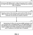
- FIG. 9 illustrates a process of obtaining CSI-RSs in accordance with an embodiment of the disclosure.
- the process of FIG. 9 may be implemented at an access terminal, such as the access terminal 120 in an example.
- the process of FIG. 9 may be performed at the access terminal in conjunction with any of the processes of FIGS. 6-8 being executed at the access point.
- the access terminal monitors a DMTC window of a Radio Frame that includes a first block of subframes (e.g., SF0-SF4) and a second block of subframes (e.g., SF5-SF9).
- the access terminal receives, based on the monitoring, a multi-subframe DRS within the DMTC window, the multi-subframe DRS including a plurality of DRS subframes that each include a plurality of symbols.
- the access terminal descrambles CSI-RSs in first and second DRS subframes of the multi-subframe DRS in accordance with a CSI-RS descrambling rule that determines how the second DRS subframe is to be descrambled based on whether the first DRS subframe is included among the first block or subframes or the second block of subframes.
- the CSI-RS descrambling rule is configured to as to be in alignment with the CSI-RS scrambling rule implemented at the access point (e.g., at block 610 of FIG. 6 , etc.) so as to avoid a scrambling mismatch.
- the access point e.g., at block 610 of FIG. 6 , etc.
- a relisting of the various scrambling/descrambling options described above with respect to FIGS. 6-9 is omitted here, as it is understood that any of the above-noted CSI-RS scrambling rules may be mapped to a corresponding CSI-RS descrambling rule at block 910 of FIG. 9 .
- FIG. 10 is a device-level diagram illustrating example components of the access point 110 and the access terminal 120 of the primary RAT system 100 in more detail.
- the access point 110 and the access terminal 120 may each generally include a wireless communication device (represented by the communication devices 1030 and 1050) for communicating with other wireless nodes via at least one designated 26 RAT.
- the communication devices 1030 and 1050 may be variously configured for transmitting and encoding signals, and, conversely, for receiving and decoding signals in accordance with the designated RAT (e.g., messages, indications, information, pilots, and so on).
- the communication devices 1030 and 1050 may include, for example, one or more transceivers, such as respective primary RAT transceivers 1032 and 1052, and, in some designs, (optional) co-located secondary RAT transceivers 1034 and 1054, respectively (corresponding, for example, to the RAT employed by the competing RAT system 150).
- a "transceiver” may include a transmitter circuit, a receiver circuit, or a combination thereof, but need not provide both transmit and receive functionalities in all designs.
- a low functionality receiver circuit may be employed in some designs to reduce costs when providing full communication is not necessary (e.g., a radio chip or similar circuitry providing low-level sniffing only).
- co-located e.g., radios, access points, transceivers, etc.
- components that are in the same housing may refer to one of various arrangements. For example, components that are in the same housing; components that are hosted by the same processor; components that are within a defined distance of one another; and/or components that are connected via an interface (e.g., an Ethernet switch) where the interface meets the latency requirements of any required inter-component communication (e.g., messaging).
- an interface e.g., an Ethernet switch
- the access point 110 and the access terminal 120 may also each generally include a communication controller (represented by the communication controllers 1040 and 1060) for controlling operation of their respective communication devices 1030 and 1050 (e.g., directing, modifying, enabling, disabling, etc.).
- the communication controllers 1040 and 1060 may include one or more processors 1042 and 1062, and one or more memories 1044 and 1064 coupled to the processors 1042 and 1062, respectively.
- the memories 1044 and 1064 may be configured to store data, instructions, or a combination thereof, either as on-board cache memory, as separate components, a combination, etc.
- the processors 1042 and 1062 and the memories 1044 and 1064 may be standalone communication components or may be part of the respective host system functionality of the access point 110 and the access terminal 120.
- the DRS scheduler 121 may be implemented in different ways. In some designs, some or all of the functionality associated therewith may be implemented by or otherwise at the direction of at least one processor (e.g., one 27 or more of the processors 1042), at least one memory (e.g., one or more of the memories 1044), at least one transceiver (e.g., one or more of the transceivers 1032 and 1034), or a combination thereof. In other designs, some or all of the functionality associated therewith may be implemented as a series of interrelated functional modules.
- processors 1042 e.g., one 27 or more of the processors 1042
- at least one memory e.g., one or more of the memories 1044
- at least one transceiver e.g., one or more of the transceivers 1032 and 1034
- some or all of the functionality associated therewith may be implemented as a series of interrelated functional modules.
- the DRS manager 122 may be implemented in different ways. In some designs, some or all of the functionality associated therewith may be implemented by or otherwise at the direction of at least one processor (e.g., one or more of the processors 1062), at least one memory (e.g., one or more of the memories 1064), at least one transceiver (e.g., one or more of the transceivers 1052 and 1054), or a combination thereof. In other designs, some or all of the functionality associated therewith may be implemented as a series of interrelated functional modules.
- processors 1062 e.g., one or more of the processors 1062
- at least one memory e.g., one or more of the memories 1064
- at least one transceiver e.g., one or more of the transceivers 1052 and 1054
- some or all of the functionality associated therewith may be implemented as a series of interrelated functional modules.
- the CSI-RS scheduler 123 may be implemented in different ways. In some designs, some or all of the functionality associated therewith may be implemented by or otherwise at the direction of at least one processor (e.g., one or more of the processors 1042), at least one memory (e.g., one or more of the memories 1044), at least one transceiver (e.g., one or more of the transceivers 1032 and 1034), or a combination thereof. In other designs, some or all of the functionality associated therewith may be implemented as a series of interrelated functional modules.
- processors 1042 e.g., one or more of the processors 1042
- at least one memory e.g., one or more of the memories 1044
- at least one transceiver e.g., one or more of the transceivers 1032 and 1034
- some or all of the functionality associated therewith may be implemented as a series of interrelated functional modules.
- FIG. 10 may be used to perform operations described above with respect to FIGS. 1 - 8 .
- any reference to an element herein using a designation such as “first,” “second,” and so forth does not generally limit the quantity or order of those elements. Rather, these designations may be used herein as a convenient method of distinguishing between two or more elements or instances of an element. Thus, a reference to first and second elements does not mean that only two elements may be employed there or that the first element must precede the second element in some manner. Also, unless stated otherwise a set of elements may comprise one or more elements.
- an apparatus or any component of an apparatus may be configured to (or made operable to or adapted to) provide functionality as taught herein. This may be achieved, for example: by manufacturing (e.g., fabricating) the apparatus or component so that it will provide the functionality; by programming the apparatus or component so that it will provide the functionality; or through the use of some other suitable implementation technique.
- an integrated circuit may be fabricated to provide the requisite functionality.
- an integrated circuit may be fabricated to support the requisite functionality and then configured (e.g., via programming) to provide the requisite functionality.
- a processor circuit may execute code to provide the requisite functionality.
- a software module may reside in Random-Access Memory (RAM), flash memory, Read-only Memory (ROM), Erasable Programmable Read-only Memory (EPROM), Electrically Erasable Programmable Read-only Memory (EEPROM), registers, hard disk, a removable disk, a CD-ROM, or any other form of storage medium known in the art, transitory or non-transitory.
- An exemplary storage medium is coupled to the processor such that the processor can read information from, and write information to, the storage medium.
- the storage medium may be integral to the processor (e.g., cache memory).
- certain aspects of the disclosure can include a transitory or non-transitory computer-readable medium embodying a method for communication.
Landscapes
- Engineering & Computer Science (AREA)
- Signal Processing (AREA)
- Computer Networks & Wireless Communication (AREA)
- Physics & Mathematics (AREA)
- Spectroscopy & Molecular Physics (AREA)
- Health & Medical Sciences (AREA)
- General Health & Medical Sciences (AREA)
- Power Engineering (AREA)
- Mobile Radio Communication Systems (AREA)
Claims (15)
- Un procédé de configuration de signaux de référence d'informations d'état de canal, CSI-RS, sur un support de communication partagé, comprenant :l'exécution (600, 700, 800) d'un protocole d'évaluation de canal libre, CCA, de façon à déterminer s'il convient de commencer une transmission à l'intérieur d'une fenêtre de configuration de synchronisation de mesure de signalisation de référence de découverte, DRS, DMTC, d'une trame radio qui comprend un premier bloc de sous-trames (SF0-SF4) et un deuxième bloc de sous-trames (SF5-SF9),la transmission (605, 705, 805), en fonction de l'exécution, d'une DRS à sous-trames multiples (300A, 300B) à l'intérieur de la fenêtre DMTC, la DRS à sous-trames multiples comprenant une pluralité de sous-trames DRS qui comprennent chacune une pluralité de symboles, etcaractérisé en ce qu'il comprend en outrel'embrouillage (610, 710, 810) de CSI-RS dans des première et deuxième sous-trames DRS de la DRS à sous-trames multiples conformément à une règle d'embrouillage de CSI-RS qui détermine comment la deuxième sous-trame DRS doit être embrouillée selon que la première sous-trame DRS est incluse dans le premier bloc de sous-trames ou le deuxième bloc de sous-trames.
- Le procédé selon la Revendication 1,où la première sous-trame DRS est incluse dans le premier bloc de sous-trames, et où, en fonction de la règle d'embrouillage de CSI-RS, l'opération d'embrouillage embrouille la deuxième sous-trame DRS conformément à l'embrouillage qui est défini pour un bloc initial du premier bloc de sous-trames, ouoù la première sous-trame DRS est incluse dans le deuxième bloc de sous-trames, et où, en fonction de la règle d'embrouillage de CSI-RS, l'opération d'embrouillage embrouille la deuxième sous-trame DRS conformément à l'embrouillage qui est défini pour un bloc initial du deuxième bloc de sous-trames.
- Le procédé selon la Revendication 1, où la règle d'embrouillage de CSI-RS est une règle d'embrouillage de CSI-RS fixe qui utilise le même embrouillage pour à la fois les première et deuxième sous-trames DRS.
- Le procédé selon la Revendication 3,où la première sous-trame DRS est incluse dans le premier bloc de sous-trames, et où, en fonction de la règle d'embrouillage de CSI-RS fixe, l'opération d'embrouillage embrouille à la fois les première et deuxième sous-trames DRS conformément à l'embrouillage qui est défini pour un bloc initial du premier bloc de sous-trames, ouoù la première sous-trame DRS est incluse dans le deuxième bloc de sous-trames, et où, en fonction de la règle d'embrouillage de CSI-RS fixe, l'opération d'embrouillage embrouille à la fois les première et deuxième sous-trames DRS conformément à l'embrouillage qui est défini pour un bloc initial du deuxième bloc de sous-trames.
- Le procédé selon la Revendication 1,où la première sous-trame DRS est transmise sur un bloc initial du premier bloc de sous-trames,où la deuxième sous-trame DRS est transmise sur un deuxième bloc du premier bloc de sous-trames, etoù, en fonction de la règle d'embrouillage de CSI-RS,l'opération d'embrouillage embrouille la deuxième sous-trame DRS conformément à l'embrouillage qui est défini pour le deuxième bloc du premier bloc de sous-trames, oul'opération d'embrouillage embrouille la deuxième sous-trame DRS conformément à l'embrouillage qui est défini pour un bloc initial du deuxième bloc de sous-trames.
- Le procédé selon la Revendication 1,où la première sous-trame DRS est transmise sur un bloc initial du deuxième bloc de sous-trames,où la deuxième sous-trame DRS est transmise sur un deuxième bloc du deuxième bloc de sous-trames, etoù, en fonction de la règle d'embrouillage de CSI-RS,l'opération d'embrouillage embrouille la deuxième sous-trame DRS conformément à l'embrouillage qui est défini pour le deuxième bloc du deuxième bloc de sous-trames, oul'opération d'embrouillage embrouille la deuxième sous-trame DRS conformément à l'embrouillage qui est défini pour un bloc initial du premier bloc de sous-trames.
- Un procédé d'obtention de signaux de référence d'informations d'état de canal, CSI-RS, sur un support de communication partagé, comprenant :la surveillance (900) d'une fenêtre de configuration de synchronisation de mesure de signalisation de référence de découverte, DRS, DMTC, d'une trame radio qui comprend un premier bloc de sous-trames (SF0-SF4) et un deuxième bloc de sous-trames (SF5-SF9),la réception (905), en fonction de la surveillance, d'une DRS à sous-trames multiples à l'intérieur de la fenêtre DMTC, la DRS à sous-trames multiples comprenant une pluralité de sous-trames DRS qui comprennent chacune une pluralité de symboles, etcaractérisé en ce qu'il comprend en outrele désembrouillage (910) de CSI-RS dans des première et deuxième sous-trames DRS de la DRS à sous-trames multiples conformément à une règle de désembrouillage de CSI-RS qui détermine comment la deuxième sous-trame DRS doit être désembrouillée selon que la première sous-trame DRS est incluse dans le premier bloc de sous-trames ou le deuxième bloc de sous-trames.
- Le procédé selon la Revendication 7,où la première sous-trame DRS est incluse dans le premier bloc de sous-trames, et où, en fonction de la règle de désembrouillage de CSI-RS, l'opération de désembrouillage désembrouille la deuxième sous-trame DRS conformément au désembrouillage qui est défini pour un bloc initial du premier bloc de sous-trames, ouoù la première sous-trame DRS est incluse dans le deuxième bloc de sous-trames, et où, en fonction de la règle de désembrouillage de CSI-RS, l'opération de désembrouillage désembrouille la deuxième sous-trame DRS conformément au désembrouillage qui est défini pour un bloc initial du deuxième bloc de sous-trames.
- Le procédé selon la Revendication 7, où la règle de désembrouillage de CSI-RS est une règle de désembrouillage de CSI-RS fixe qui utilise le même désembrouillage pour à la fois les première et deuxième sous-trames DRS, et où :la première sous-trame DRS est incluse dans le premier bloc de sous-trames, et où, en fonction de la règle de désembrouillage de CSI-RS fixe, l'opération de désembrouillage désembrouille à la fois les première et deuxième sous-trames DRS conformément au désembrouillage qui est défini pour un bloc initial du premier bloc de sous-trames, oula première sous-trame DRS est incluse dans le deuxième bloc de sous-trames, et où, en fonction de la règle de désembrouillage de CSI-RS fixe, l'opération de désembrouillage désembrouille à la fois les première et deuxième sous-trames DRS conformément au désembrouillage qui est défini pour un bloc initial du deuxième bloc de sous-trames.
- Le procédé selon la Revendication 7,où la première sous-trame DRS est reçue sur un bloc initial du premier bloc de sous-trames,où la deuxième sous-trame DRS est reçue sur un deuxième bloc du premier bloc de sous-trames, etoù, en fonction de la règle de désembrouillage de CSI-RS,l'opération de désembrouillage désembrouille la deuxième sous-trame DRS conformément au désembrouillage qui est défini pour le deuxième bloc du premier bloc de sous-trames, oul'opération de désembrouillage désembrouille la deuxième sous-trame DRS conformément au désembrouillage qui est défini pour un bloc initial du deuxième bloc de sous-trames.
- Le procédé selon la Revendication 7,où la première sous-trame DRS est transmise sur un bloc initial du deuxième bloc de sous-trames,où la deuxième sous-trame DRS est transmise sur un deuxième bloc du deuxième bloc de sous-trames, etoù, en fonction de la règle d'embrouillage de CSI-RS,l'opération d'embrouillage embrouille la deuxième sous-trame DRS conformément à l'embrouillage qui est défini pour le deuxième bloc du deuxième bloc de sous-trames, oul'opération de désembrouillage désembrouille la deuxième sous-trame DRS conformément au désembrouillage qui est défini pour un bloc initial du premier bloc de sous-trames.
- Un point d'accès destiné à la configuration de signaux de référence d'informations d'état de canal, CSI-RS, sur un support de communication partagé, comprenant :un moyen d'exécution d'un protocole d'évaluation de canal libre, CCA, de façon à déterminer s'il convient de commencer une transmission à l'intérieur d'une fenêtre de configuration de synchronisation de mesure de signalisation de référence de découverte, DRS, DMTC, d'une trame radio qui comprend un premier bloc de sous-trames (SF0-SF4) et un deuxième bloc de sous-trames (SF5-SF9),un moyen de transmission, en fonction de l'exécution, d'une DRS à sous-trames multiples à l'intérieur de la fenêtre DMTC, la DRS à sous-trames multiples comprenant une pluralité de sous-trames DRS qui comprennent chacune une pluralité de symboles, etcaractérisé en ce qu'il comprend en outreun moyen d'embrouillage de CSI-RS dans des première et deuxième sous-trames DRS de la DRS à sous-trames multiples conformément à une règle d'embrouillage de CSI-RS qui détermine comment la deuxième sous-trame DRS doit être embrouillée selon que la première sous-trame DRS est incluse dans le premier bloc de sous-trames ou le deuxième bloc de sous-trames.
- Un équipement d'utilisateur, UE, configuré de façon à obtenir des signaux de référence d'informations d'état de canal, CSI-RS, sur un support de communication partagé, comprenant :un moyen de surveillance d'une fenêtre de configuration de synchronisation de mesure de signalisation de référence de découverte, DRS, DMTC, d'une trame radio qui comprend un premier bloc de sous-trames (SF0-SF4) et un deuxième bloc de sous-trames (SF5-SF9),un moyen de réception, en fonction de la surveillance, d'une DRS à sous-trames multiples à l'intérieur de la fenêtre DMTC, la DRS à sous-trames multiples comprenant une pluralité de sous-trames DRS qui comprennent chacune une pluralité de symboles, etcaractérisé en ce qu'il comprend en outreun moyen de désembrouillage de CSI-RS dans des première et deuxième sous-trames DRS de la DRS à sous-trames multiples conformément à une règle de désembrouillage de CSI-RS qui détermine comment la deuxième sous-trame DRS doit être désembrouillée selon que la première sous-trame DRS est incluse dans le premier bloc de sous-trames ou le deuxième bloc de sous-trames.
- Un support lisible par ordinateur contenant des instructions conservées en mémoire sur celui-ci qui, lorsqu'elles sont exécutées par un point d'accès destiné à la configuration de signaux de référence d'informations d'état de canal, CSI-RS, sur un support de communication partagé, amènent le point d'accès à exécuter un procédé selon l'une quelconque des Revendications 1 à 6.
- Un support lisible par ordinateur contenant des instructions conservées en mémoire sur celui-ci qui, lorsqu'elles sont exécutées par un équipement d'utilisateur, UE, configuré de façon à obtenir des signaux de référence d'informations d'état de canal, CSI-RS, sur un support de communication partagé, amènent le point d'accès à exécuter un procédé selon l'une quelconque des Revendications 7 à 11.
Applications Claiming Priority (3)
| Application Number | Priority Date | Filing Date | Title |
|---|---|---|---|
| US201762561186P | 2017-09-20 | 2017-09-20 | |
| US16/134,534 US10652914B2 (en) | 2017-09-20 | 2018-09-18 | CSI-RS scrambling of subframes in a multi-subframe DRS |
| PCT/US2018/051893 WO2019060512A1 (fr) | 2017-09-20 | 2018-09-20 | Brouillage csi-rs de sous-trames dans une drs à sous-trames multiples |
Publications (2)
| Publication Number | Publication Date |
|---|---|
| EP3685541A1 EP3685541A1 (fr) | 2020-07-29 |
| EP3685541B1 true EP3685541B1 (fr) | 2022-08-24 |
Family
ID=65721655
Family Applications (1)
| Application Number | Title | Priority Date | Filing Date |
|---|---|---|---|
| EP18789288.0A Active EP3685541B1 (fr) | 2017-09-20 | 2018-09-20 | Brouillage csi-rs de sous-trames dans une drs à sous-trames multiples |
Country Status (9)
| Country | Link |
|---|---|
| US (2) | US10652914B2 (fr) |
| EP (1) | EP3685541B1 (fr) |
| JP (1) | JP2020534755A (fr) |
| KR (1) | KR20200052892A (fr) |
| CN (1) | CN111108713B (fr) |
| BR (1) | BR112020005365A2 (fr) |
| CA (1) | CA3072930A1 (fr) |
| TW (1) | TW201921984A (fr) |
| WO (1) | WO2019060512A1 (fr) |
Families Citing this family (10)
| Publication number | Priority date | Publication date | Assignee | Title |
|---|---|---|---|---|
| US10652914B2 (en) * | 2017-09-20 | 2020-05-12 | Qualcomm Incorporated | CSI-RS scrambling of subframes in a multi-subframe DRS |
| EP3726888A4 (fr) * | 2017-12-20 | 2020-11-25 | Beijing Xiaomi Mobile Software Co., Ltd. | Procédé et dispositif d'extension de pbch |
| US11290172B2 (en) | 2018-11-27 | 2022-03-29 | XCOM Labs, Inc. | Non-coherent cooperative multiple-input multiple-output communications |
| US10911079B2 (en) * | 2019-06-19 | 2021-02-02 | Realtek Semiconductor Corp. | Transmitter, communication system and transmission method |
| US11411778B2 (en) | 2019-07-12 | 2022-08-09 | XCOM Labs, Inc. | Time-division duplex multiple input multiple output calibration |
| US11411779B2 (en) | 2020-03-31 | 2022-08-09 | XCOM Labs, Inc. | Reference signal channel estimation |
| CA3175361A1 (fr) | 2020-04-15 | 2021-10-21 | Tamer Adel Kadous | Association et diversite multipoint de reseau sans fil |
| CA3178604A1 (fr) | 2020-05-26 | 2021-12-02 | XCOM Labs, Inc. | Formation de faisceaux tenant compte du brouillage |
| KR20230091910A (ko) | 2020-10-19 | 2023-06-23 | 엑스콤 랩스 인코퍼레이티드 | 무선 통신 시스템에서의 참조 신호 |
| WO2022093988A1 (fr) | 2020-10-30 | 2022-05-05 | XCOM Labs, Inc. | Groupement et/ou sélection de débit dans des systèmes de communication à entrées et sorties multiples |
Family Cites Families (24)
| Publication number | Priority date | Publication date | Assignee | Title |
|---|---|---|---|---|
| US8260356B2 (en) * | 2009-06-18 | 2012-09-04 | Samsung Electronics Co., Ltd. | Method and system for indicating method used to scramble dedicated reference signals |
| US8300587B2 (en) * | 2009-08-17 | 2012-10-30 | Nokia Corporation | Initialization of reference signal scrambling |
| CN102056309A (zh) * | 2009-11-02 | 2011-05-11 | 北京三星通信技术研究有限公司 | 一种传输专用参考信号的方法和装置 |
| KR101901927B1 (ko) * | 2010-09-28 | 2018-09-27 | 엘지전자 주식회사 | 무선 통신 시스템에서 셀간 간섭 조정 방법 및 장치 |
| CN106165323B (zh) * | 2014-03-04 | 2018-10-12 | Lg电子株式会社 | 接收用于接收发现参考信号的控制信息的方法及其装置 |
| WO2015160171A1 (fr) * | 2014-04-17 | 2015-10-22 | 엘지전자 주식회사 | Procédé et terminal de détection d'un signal de découverte |
| KR101857897B1 (ko) * | 2014-04-24 | 2018-06-19 | 엘지전자 주식회사 | 측정 수행 방법 및 단말 |
| WO2016018079A1 (fr) * | 2014-08-01 | 2016-02-04 | 엘지전자 주식회사 | Procédé de réception de signaux en liaison descendante et équipement d'utilisateur, et procédé d'émission de signaux en liaison descendante et station de base |
| CN105338566B (zh) * | 2014-08-07 | 2019-06-04 | 上海诺基亚贝尔股份有限公司 | 通信系统中用于测量增强的方法和装置 |
| WO2016020011A1 (fr) * | 2014-08-08 | 2016-02-11 | Nokia Solutions And Networks Oy | Détermination de modèles d'intervalle de mesure |
| WO2016036154A1 (fr) * | 2014-09-04 | 2016-03-10 | 엘지전자(주) | Procédé destiné à réaliser une localisation dans un système de communication sans fil, et dispositif s'y rapportant |
| US10959197B2 (en) * | 2014-09-08 | 2021-03-23 | Samsung Electronics Co., Ltd. | Cell detection, synchronization and measurement on unlicensed spectrum |
| US10735155B2 (en) * | 2014-11-03 | 2020-08-04 | Qualcomm Incorporated | Rate matching around reference signals in wireless communications |
| US10129782B2 (en) * | 2015-01-30 | 2018-11-13 | Samsung Electronics Co., Ltd. | Methods and apparatus for CSI measurement configuration and reporting on unlicensed spectrum |
| WO2017023056A1 (fr) * | 2015-07-31 | 2017-02-09 | 삼성전자 주식회사 | Procédé pour transmettre un signal sur la base d'une estimation de canal libre dans un canal à bande sans licence, et système de communication mobile |
| EP3335353B8 (fr) * | 2015-08-13 | 2021-01-20 | Apple Inc. | Transmission de signal de référence de découverte pour lte dans une bande sans licence |
| US10630432B2 (en) * | 2015-10-13 | 2020-04-21 | Lg Electronics Inc. | Method and apparatus for transmitting or receiving sub-frame length information in wireless access system supporting non-licensed band |
| US10958404B2 (en) * | 2015-11-06 | 2021-03-23 | Qualcomm Incorporated | Discovery reference signal configuration and scrambling in licensed-assisted access |
| US10548055B2 (en) * | 2015-12-08 | 2020-01-28 | Telefonaktiebolaget Lm Ericsson (Publ) | Network node, wireless device, methods and computer programs |
| WO2017110961A1 (fr) * | 2015-12-25 | 2017-06-29 | 株式会社Nttドコモ | Terminal utilisateur, station de base sans fil et procédé de communication sans fil |
| US10142980B2 (en) * | 2016-02-26 | 2018-11-27 | Qualcomm Incorporated | Discovery reference signal transmission window detection and discovery reference signal measurement configuration |
| CN107276714B (zh) * | 2016-04-08 | 2020-11-24 | 北京佰才邦技术有限公司 | 解调方法、装置、终端及系统 |
| TWI700958B (zh) * | 2017-06-16 | 2020-08-01 | 聯發科技股份有限公司 | 用於新無線電網絡的無線資源管理量測 |
| US10652914B2 (en) * | 2017-09-20 | 2020-05-12 | Qualcomm Incorporated | CSI-RS scrambling of subframes in a multi-subframe DRS |
-
2018
- 2018-09-18 US US16/134,534 patent/US10652914B2/en not_active Expired - Fee Related
- 2018-09-20 BR BR112020005365-1A patent/BR112020005365A2/pt unknown
- 2018-09-20 TW TW107133120A patent/TW201921984A/zh unknown
- 2018-09-20 EP EP18789288.0A patent/EP3685541B1/fr active Active
- 2018-09-20 KR KR1020207007866A patent/KR20200052892A/ko not_active Application Discontinuation
- 2018-09-20 JP JP2020516475A patent/JP2020534755A/ja active Pending
- 2018-09-20 CA CA3072930A patent/CA3072930A1/fr active Pending
- 2018-09-20 WO PCT/US2018/051893 patent/WO2019060512A1/fr unknown
- 2018-09-20 CN CN201880060079.3A patent/CN111108713B/zh active Active
-
2020
- 2020-05-08 US US16/870,782 patent/US11153892B2/en active Active
Also Published As
| Publication number | Publication date |
|---|---|
| TW201921984A (zh) | 2019-06-01 |
| EP3685541A1 (fr) | 2020-07-29 |
| KR20200052892A (ko) | 2020-05-15 |
| CN111108713A (zh) | 2020-05-05 |
| WO2019060512A1 (fr) | 2019-03-28 |
| US11153892B2 (en) | 2021-10-19 |
| BR112020005365A2 (pt) | 2020-09-24 |
| JP2020534755A (ja) | 2020-11-26 |
| CA3072930A1 (fr) | 2019-03-28 |
| US10652914B2 (en) | 2020-05-12 |
| CN111108713B (zh) | 2022-07-12 |
| US20190090256A1 (en) | 2019-03-21 |
| US20200344775A1 (en) | 2020-10-29 |
Similar Documents
| Publication | Publication Date | Title |
|---|---|---|
| EP3577843B1 (fr) | Fenêtre de configuration de synchronisation de mesure de signal de référence de découverte (drs) de sous-trames multiples | |
| EP3685541B1 (fr) | Brouillage csi-rs de sous-trames dans une drs à sous-trames multiples | |
| AU2017212617B2 (en) | Indicating additional PBCH symbols in unlicensed small cell environment | |
| US10178649B2 (en) | Paging user equipments on a shared communication medium | |
| US10674389B2 (en) | Access terminal radio link monitoring (RLM) on a shared communication medium | |
| US10827471B2 (en) | Uplink procedures on a wireless communication medium | |
| CN116405175A (zh) | 共享通信介质上的自主上行链路传输 |
Legal Events
| Date | Code | Title | Description |
|---|---|---|---|
| STAA | Information on the status of an ep patent application or granted ep patent |
Free format text: STATUS: UNKNOWN |
|
| STAA | Information on the status of an ep patent application or granted ep patent |
Free format text: STATUS: THE INTERNATIONAL PUBLICATION HAS BEEN MADE |
|
| PUAI | Public reference made under article 153(3) epc to a published international application that has entered the european phase |
Free format text: ORIGINAL CODE: 0009012 |
|
| STAA | Information on the status of an ep patent application or granted ep patent |
Free format text: STATUS: REQUEST FOR EXAMINATION WAS MADE |
|
| 17P | Request for examination filed |
Effective date: 20200213 |
|
| AK | Designated contracting states |
Kind code of ref document: A1 Designated state(s): AL AT BE BG CH CY CZ DE DK EE ES FI FR GB GR HR HU IE IS IT LI LT LU LV MC MK MT NL NO PL PT RO RS SE SI SK SM TR |
|
| AX | Request for extension of the european patent |
Extension state: BA ME |
|
| DAV | Request for validation of the european patent (deleted) | ||
| DAX | Request for extension of the european patent (deleted) | ||
| RIC1 | Information provided on ipc code assigned before grant |
Ipc: H04W 74/08 20090101ALI20220127BHEP Ipc: H04L 27/00 20060101ALI20220127BHEP Ipc: H04L 5/00 20060101AFI20220127BHEP |
|
| GRAP | Despatch of communication of intention to grant a patent |
Free format text: ORIGINAL CODE: EPIDOSNIGR1 |
|
| STAA | Information on the status of an ep patent application or granted ep patent |
Free format text: STATUS: GRANT OF PATENT IS INTENDED |
|
| INTG | Intention to grant announced |
Effective date: 20220318 |
|
| GRAS | Grant fee paid |
Free format text: ORIGINAL CODE: EPIDOSNIGR3 |
|
| GRAA | (expected) grant |
Free format text: ORIGINAL CODE: 0009210 |
|
| STAA | Information on the status of an ep patent application or granted ep patent |
Free format text: STATUS: THE PATENT HAS BEEN GRANTED |
|
| AK | Designated contracting states |
Kind code of ref document: B1 Designated state(s): AL AT BE BG CH CY CZ DE DK EE ES FI FR GB GR HR HU IE IS IT LI LT LU LV MC MK MT NL NO PL PT RO RS SE SI SK SM TR |
|
| REG | Reference to a national code |
Ref country code: CH Ref legal event code: EP |
|
| REG | Reference to a national code |
Ref country code: IE Ref legal event code: FG4D |
|
| REG | Reference to a national code |
Ref country code: AT Ref legal event code: REF Ref document number: 1514430 Country of ref document: AT Kind code of ref document: T Effective date: 20220915 Ref country code: DE Ref legal event code: R096 Ref document number: 602018039778 Country of ref document: DE |
|
| REG | Reference to a national code |
Ref country code: LT Ref legal event code: MG9D |
|
| REG | Reference to a national code |
Ref country code: NL Ref legal event code: MP Effective date: 20220824 |
|
| PG25 | Lapsed in a contracting state [announced via postgrant information from national office to epo] |
Ref country code: SE Free format text: LAPSE BECAUSE OF FAILURE TO SUBMIT A TRANSLATION OF THE DESCRIPTION OR TO PAY THE FEE WITHIN THE PRESCRIBED TIME-LIMIT Effective date: 20220824 Ref country code: RS Free format text: LAPSE BECAUSE OF FAILURE TO SUBMIT A TRANSLATION OF THE DESCRIPTION OR TO PAY THE FEE WITHIN THE PRESCRIBED TIME-LIMIT Effective date: 20220824 Ref country code: PT Free format text: LAPSE BECAUSE OF FAILURE TO SUBMIT A TRANSLATION OF THE DESCRIPTION OR TO PAY THE FEE WITHIN THE PRESCRIBED TIME-LIMIT Effective date: 20221226 Ref country code: NO Free format text: LAPSE BECAUSE OF FAILURE TO SUBMIT A TRANSLATION OF THE DESCRIPTION OR TO PAY THE FEE WITHIN THE PRESCRIBED TIME-LIMIT Effective date: 20221124 Ref country code: NL Free format text: LAPSE BECAUSE OF FAILURE TO SUBMIT A TRANSLATION OF THE DESCRIPTION OR TO PAY THE FEE WITHIN THE PRESCRIBED TIME-LIMIT Effective date: 20220824 Ref country code: LV Free format text: LAPSE BECAUSE OF FAILURE TO SUBMIT A TRANSLATION OF THE DESCRIPTION OR TO PAY THE FEE WITHIN THE PRESCRIBED TIME-LIMIT Effective date: 20220824 Ref country code: LT Free format text: LAPSE BECAUSE OF FAILURE TO SUBMIT A TRANSLATION OF THE DESCRIPTION OR TO PAY THE FEE WITHIN THE PRESCRIBED TIME-LIMIT Effective date: 20220824 Ref country code: FI Free format text: LAPSE BECAUSE OF FAILURE TO SUBMIT A TRANSLATION OF THE DESCRIPTION OR TO PAY THE FEE WITHIN THE PRESCRIBED TIME-LIMIT Effective date: 20220824 |
|
| REG | Reference to a national code |
Ref country code: AT Ref legal event code: MK05 Ref document number: 1514430 Country of ref document: AT Kind code of ref document: T Effective date: 20220824 |
|
| PG25 | Lapsed in a contracting state [announced via postgrant information from national office to epo] |
Ref country code: PL Free format text: LAPSE BECAUSE OF FAILURE TO SUBMIT A TRANSLATION OF THE DESCRIPTION OR TO PAY THE FEE WITHIN THE PRESCRIBED TIME-LIMIT Effective date: 20220824 Ref country code: IS Free format text: LAPSE BECAUSE OF FAILURE TO SUBMIT A TRANSLATION OF THE DESCRIPTION OR TO PAY THE FEE WITHIN THE PRESCRIBED TIME-LIMIT Effective date: 20221224 Ref country code: HR Free format text: LAPSE BECAUSE OF FAILURE TO SUBMIT A TRANSLATION OF THE DESCRIPTION OR TO PAY THE FEE WITHIN THE PRESCRIBED TIME-LIMIT Effective date: 20220824 Ref country code: GR Free format text: LAPSE BECAUSE OF FAILURE TO SUBMIT A TRANSLATION OF THE DESCRIPTION OR TO PAY THE FEE WITHIN THE PRESCRIBED TIME-LIMIT Effective date: 20221125 |
|
| PG25 | Lapsed in a contracting state [announced via postgrant information from national office to epo] |
Ref country code: SM Free format text: LAPSE BECAUSE OF FAILURE TO SUBMIT A TRANSLATION OF THE DESCRIPTION OR TO PAY THE FEE WITHIN THE PRESCRIBED TIME-LIMIT Effective date: 20220824 Ref country code: RO Free format text: LAPSE BECAUSE OF FAILURE TO SUBMIT A TRANSLATION OF THE DESCRIPTION OR TO PAY THE FEE WITHIN THE PRESCRIBED TIME-LIMIT Effective date: 20220824 Ref country code: ES Free format text: LAPSE BECAUSE OF FAILURE TO SUBMIT A TRANSLATION OF THE DESCRIPTION OR TO PAY THE FEE WITHIN THE PRESCRIBED TIME-LIMIT Effective date: 20220824 Ref country code: DK Free format text: LAPSE BECAUSE OF FAILURE TO SUBMIT A TRANSLATION OF THE DESCRIPTION OR TO PAY THE FEE WITHIN THE PRESCRIBED TIME-LIMIT Effective date: 20220824 Ref country code: CZ Free format text: LAPSE BECAUSE OF FAILURE TO SUBMIT A TRANSLATION OF THE DESCRIPTION OR TO PAY THE FEE WITHIN THE PRESCRIBED TIME-LIMIT Effective date: 20220824 Ref country code: AT Free format text: LAPSE BECAUSE OF FAILURE TO SUBMIT A TRANSLATION OF THE DESCRIPTION OR TO PAY THE FEE WITHIN THE PRESCRIBED TIME-LIMIT Effective date: 20220824 |
|
| REG | Reference to a national code |
Ref country code: CH Ref legal event code: PL |
|
| REG | Reference to a national code |
Ref country code: DE Ref legal event code: R097 Ref document number: 602018039778 Country of ref document: DE Ref country code: BE Ref legal event code: MM Effective date: 20220930 |
|
| PG25 | Lapsed in a contracting state [announced via postgrant information from national office to epo] |
Ref country code: SK Free format text: LAPSE BECAUSE OF FAILURE TO SUBMIT A TRANSLATION OF THE DESCRIPTION OR TO PAY THE FEE WITHIN THE PRESCRIBED TIME-LIMIT Effective date: 20220824 Ref country code: MC Free format text: LAPSE BECAUSE OF FAILURE TO SUBMIT A TRANSLATION OF THE DESCRIPTION OR TO PAY THE FEE WITHIN THE PRESCRIBED TIME-LIMIT Effective date: 20220824 Ref country code: EE Free format text: LAPSE BECAUSE OF FAILURE TO SUBMIT A TRANSLATION OF THE DESCRIPTION OR TO PAY THE FEE WITHIN THE PRESCRIBED TIME-LIMIT Effective date: 20220824 |
|
| PG25 | Lapsed in a contracting state [announced via postgrant information from national office to epo] |
Ref country code: LU Free format text: LAPSE BECAUSE OF NON-PAYMENT OF DUE FEES Effective date: 20220920 Ref country code: AL Free format text: LAPSE BECAUSE OF FAILURE TO SUBMIT A TRANSLATION OF THE DESCRIPTION OR TO PAY THE FEE WITHIN THE PRESCRIBED TIME-LIMIT Effective date: 20220824 |
|
| PLBE | No opposition filed within time limit |
Free format text: ORIGINAL CODE: 0009261 |
|
| STAA | Information on the status of an ep patent application or granted ep patent |
Free format text: STATUS: NO OPPOSITION FILED WITHIN TIME LIMIT |
|
| PG25 | Lapsed in a contracting state [announced via postgrant information from national office to epo] |
Ref country code: LI Free format text: LAPSE BECAUSE OF NON-PAYMENT OF DUE FEES Effective date: 20220930 Ref country code: IE Free format text: LAPSE BECAUSE OF NON-PAYMENT OF DUE FEES Effective date: 20220920 Ref country code: CH Free format text: LAPSE BECAUSE OF NON-PAYMENT OF DUE FEES Effective date: 20220930 |
|
| 26N | No opposition filed |
Effective date: 20230525 |
|
| PG25 | Lapsed in a contracting state [announced via postgrant information from national office to epo] |
Ref country code: SI Free format text: LAPSE BECAUSE OF FAILURE TO SUBMIT A TRANSLATION OF THE DESCRIPTION OR TO PAY THE FEE WITHIN THE PRESCRIBED TIME-LIMIT Effective date: 20220824 |
|
| PG25 | Lapsed in a contracting state [announced via postgrant information from national office to epo] |
Ref country code: BE Free format text: LAPSE BECAUSE OF NON-PAYMENT OF DUE FEES Effective date: 20220930 |
|
| PGFP | Annual fee paid to national office [announced via postgrant information from national office to epo] |
Ref country code: GB Payment date: 20230810 Year of fee payment: 6 |
|
| PGFP | Annual fee paid to national office [announced via postgrant information from national office to epo] |
Ref country code: FR Payment date: 20230807 Year of fee payment: 6 Ref country code: DE Payment date: 20230808 Year of fee payment: 6 |
|
| PG25 | Lapsed in a contracting state [announced via postgrant information from national office to epo] |
Ref country code: CY Free format text: LAPSE BECAUSE OF FAILURE TO SUBMIT A TRANSLATION OF THE DESCRIPTION OR TO PAY THE FEE WITHIN THE PRESCRIBED TIME-LIMIT Effective date: 20220824 |
|
| PG25 | Lapsed in a contracting state [announced via postgrant information from national office to epo] |
Ref country code: MK Free format text: LAPSE BECAUSE OF FAILURE TO SUBMIT A TRANSLATION OF THE DESCRIPTION OR TO PAY THE FEE WITHIN THE PRESCRIBED TIME-LIMIT Effective date: 20220824 Ref country code: IT Free format text: LAPSE BECAUSE OF FAILURE TO SUBMIT A TRANSLATION OF THE DESCRIPTION OR TO PAY THE FEE WITHIN THE PRESCRIBED TIME-LIMIT Effective date: 20220824 Ref country code: HU Free format text: LAPSE BECAUSE OF FAILURE TO SUBMIT A TRANSLATION OF THE DESCRIPTION OR TO PAY THE FEE WITHIN THE PRESCRIBED TIME-LIMIT; INVALID AB INITIO Effective date: 20180920 |
|
| PG25 | Lapsed in a contracting state [announced via postgrant information from national office to epo] |
Ref country code: BG Free format text: LAPSE BECAUSE OF FAILURE TO SUBMIT A TRANSLATION OF THE DESCRIPTION OR TO PAY THE FEE WITHIN THE PRESCRIBED TIME-LIMIT Effective date: 20220824 |
|
| PG25 | Lapsed in a contracting state [announced via postgrant information from national office to epo] |
Ref country code: MT Free format text: LAPSE BECAUSE OF FAILURE TO SUBMIT A TRANSLATION OF THE DESCRIPTION OR TO PAY THE FEE WITHIN THE PRESCRIBED TIME-LIMIT Effective date: 20220824 |