EP3684586B1 - Continuous blow moulding method - Google Patents
Continuous blow moulding method Download PDFInfo
- Publication number
- EP3684586B1 EP3684586B1 EP18859426.1A EP18859426A EP3684586B1 EP 3684586 B1 EP3684586 B1 EP 3684586B1 EP 18859426 A EP18859426 A EP 18859426A EP 3684586 B1 EP3684586 B1 EP 3684586B1
- Authority
- EP
- European Patent Office
- Prior art keywords
- preform
- preforms
- handle
- mandrel
- blow
- Prior art date
- Legal status (The legal status is an assumption and is not a legal conclusion. Google has not performed a legal analysis and makes no representation as to the accuracy of the status listed.)
- Active
Links
Images


Classifications
-
- B—PERFORMING OPERATIONS; TRANSPORTING
- B29—WORKING OF PLASTICS; WORKING OF SUBSTANCES IN A PLASTIC STATE IN GENERAL
- B29C—SHAPING OR JOINING OF PLASTICS; SHAPING OF MATERIAL IN A PLASTIC STATE, NOT OTHERWISE PROVIDED FOR; AFTER-TREATMENT OF THE SHAPED PRODUCTS, e.g. REPAIRING
- B29C49/00—Blow-moulding, i.e. blowing a preform or parison to a desired shape within a mould; Apparatus therefor
- B29C49/42—Component parts, details or accessories; Auxiliary operations
- B29C49/64—Heating or cooling preforms, parisons or blown articles
- B29C49/6409—Thermal conditioning of preforms
- B29C49/6418—Heating of preforms
-
- B—PERFORMING OPERATIONS; TRANSPORTING
- B29—WORKING OF PLASTICS; WORKING OF SUBSTANCES IN A PLASTIC STATE IN GENERAL
- B29C—SHAPING OR JOINING OF PLASTICS; SHAPING OF MATERIAL IN A PLASTIC STATE, NOT OTHERWISE PROVIDED FOR; AFTER-TREATMENT OF THE SHAPED PRODUCTS, e.g. REPAIRING
- B29C49/00—Blow-moulding, i.e. blowing a preform or parison to a desired shape within a mould; Apparatus therefor
- B29C49/02—Combined blow-moulding and manufacture of the preform or the parison
- B29C49/06—Injection blow-moulding
- B29C49/061—Injection blow-moulding with parison holding means displaceable between injection and blow stations
- B29C49/062—Injection blow-moulding with parison holding means displaceable between injection and blow stations following an arcuate path, e.g. rotary or oscillating-type
-
- B—PERFORMING OPERATIONS; TRANSPORTING
- B29—WORKING OF PLASTICS; WORKING OF SUBSTANCES IN A PLASTIC STATE IN GENERAL
- B29B—PREPARATION OR PRETREATMENT OF THE MATERIAL TO BE SHAPED; MAKING GRANULES OR PREFORMS; RECOVERY OF PLASTICS OR OTHER CONSTITUENTS OF WASTE MATERIAL CONTAINING PLASTICS
- B29B11/00—Making preforms
- B29B11/06—Making preforms by moulding the material
- B29B11/08—Injection moulding
-
- B—PERFORMING OPERATIONS; TRANSPORTING
- B29—WORKING OF PLASTICS; WORKING OF SUBSTANCES IN A PLASTIC STATE IN GENERAL
- B29B—PREPARATION OR PRETREATMENT OF THE MATERIAL TO BE SHAPED; MAKING GRANULES OR PREFORMS; RECOVERY OF PLASTICS OR OTHER CONSTITUENTS OF WASTE MATERIAL CONTAINING PLASTICS
- B29B13/00—Conditioning or physical treatment of the material to be shaped
- B29B13/02—Conditioning or physical treatment of the material to be shaped by heating
-
- B—PERFORMING OPERATIONS; TRANSPORTING
- B29—WORKING OF PLASTICS; WORKING OF SUBSTANCES IN A PLASTIC STATE IN GENERAL
- B29C—SHAPING OR JOINING OF PLASTICS; SHAPING OF MATERIAL IN A PLASTIC STATE, NOT OTHERWISE PROVIDED FOR; AFTER-TREATMENT OF THE SHAPED PRODUCTS, e.g. REPAIRING
- B29C31/00—Handling, e.g. feeding of the material to be shaped, storage of plastics material before moulding; Automation, i.e. automated handling lines in plastics processing plants, e.g. using manipulators or robots
- B29C31/002—Handling tubes, e.g. transferring between shaping stations, loading on mandrels
-
- B—PERFORMING OPERATIONS; TRANSPORTING
- B29—WORKING OF PLASTICS; WORKING OF SUBSTANCES IN A PLASTIC STATE IN GENERAL
- B29C—SHAPING OR JOINING OF PLASTICS; SHAPING OF MATERIAL IN A PLASTIC STATE, NOT OTHERWISE PROVIDED FOR; AFTER-TREATMENT OF THE SHAPED PRODUCTS, e.g. REPAIRING
- B29C31/00—Handling, e.g. feeding of the material to be shaped, storage of plastics material before moulding; Automation, i.e. automated handling lines in plastics processing plants, e.g. using manipulators or robots
- B29C31/008—Handling preformed parts, e.g. inserts
-
- B—PERFORMING OPERATIONS; TRANSPORTING
- B29—WORKING OF PLASTICS; WORKING OF SUBSTANCES IN A PLASTIC STATE IN GENERAL
- B29C—SHAPING OR JOINING OF PLASTICS; SHAPING OF MATERIAL IN A PLASTIC STATE, NOT OTHERWISE PROVIDED FOR; AFTER-TREATMENT OF THE SHAPED PRODUCTS, e.g. REPAIRING
- B29C31/00—Handling, e.g. feeding of the material to be shaped, storage of plastics material before moulding; Automation, i.e. automated handling lines in plastics processing plants, e.g. using manipulators or robots
- B29C31/04—Feeding of the material to be moulded, e.g. into a mould cavity
- B29C31/08—Feeding of the material to be moulded, e.g. into a mould cavity of preforms to be moulded, e.g. tablets, fibre reinforced preforms, extruded ribbons, tubes or profiles; Manipulating means specially adapted for feeding preforms, e.g. supports conveyors
- B29C31/085—Feeding of the material to be moulded, e.g. into a mould cavity of preforms to be moulded, e.g. tablets, fibre reinforced preforms, extruded ribbons, tubes or profiles; Manipulating means specially adapted for feeding preforms, e.g. supports conveyors combined with positioning the preforms according to predetermined patterns, e.g. positioning extruded preforms on conveyors
-
- B—PERFORMING OPERATIONS; TRANSPORTING
- B29—WORKING OF PLASTICS; WORKING OF SUBSTANCES IN A PLASTIC STATE IN GENERAL
- B29C—SHAPING OR JOINING OF PLASTICS; SHAPING OF MATERIAL IN A PLASTIC STATE, NOT OTHERWISE PROVIDED FOR; AFTER-TREATMENT OF THE SHAPED PRODUCTS, e.g. REPAIRING
- B29C33/00—Moulds or cores; Details thereof or accessories therefor
- B29C33/0033—Moulds or cores; Details thereof or accessories therefor constructed for making articles provided with holes
-
- B—PERFORMING OPERATIONS; TRANSPORTING
- B29—WORKING OF PLASTICS; WORKING OF SUBSTANCES IN A PLASTIC STATE IN GENERAL
- B29C—SHAPING OR JOINING OF PLASTICS; SHAPING OF MATERIAL IN A PLASTIC STATE, NOT OTHERWISE PROVIDED FOR; AFTER-TREATMENT OF THE SHAPED PRODUCTS, e.g. REPAIRING
- B29C33/00—Moulds or cores; Details thereof or accessories therefor
- B29C33/30—Mounting, exchanging or centering
-
- B—PERFORMING OPERATIONS; TRANSPORTING
- B29—WORKING OF PLASTICS; WORKING OF SUBSTANCES IN A PLASTIC STATE IN GENERAL
- B29C—SHAPING OR JOINING OF PLASTICS; SHAPING OF MATERIAL IN A PLASTIC STATE, NOT OTHERWISE PROVIDED FOR; AFTER-TREATMENT OF THE SHAPED PRODUCTS, e.g. REPAIRING
- B29C45/00—Injection moulding, i.e. forcing the required volume of moulding material through a nozzle into a closed mould; Apparatus therefor
- B29C45/03—Injection moulding apparatus
- B29C45/04—Injection moulding apparatus using movable moulds or mould halves
- B29C45/0408—Injection moulding apparatus using movable moulds or mould halves involving at least a linear movement
- B29C45/0416—Injection moulding apparatus using movable moulds or mould halves involving at least a linear movement co-operating with fixed mould halves
-
- B—PERFORMING OPERATIONS; TRANSPORTING
- B29—WORKING OF PLASTICS; WORKING OF SUBSTANCES IN A PLASTIC STATE IN GENERAL
- B29C—SHAPING OR JOINING OF PLASTICS; SHAPING OF MATERIAL IN A PLASTIC STATE, NOT OTHERWISE PROVIDED FOR; AFTER-TREATMENT OF THE SHAPED PRODUCTS, e.g. REPAIRING
- B29C49/00—Blow-moulding, i.e. blowing a preform or parison to a desired shape within a mould; Apparatus therefor
- B29C49/02—Combined blow-moulding and manufacture of the preform or the parison
- B29C49/06—Injection blow-moulding
-
- B—PERFORMING OPERATIONS; TRANSPORTING
- B29—WORKING OF PLASTICS; WORKING OF SUBSTANCES IN A PLASTIC STATE IN GENERAL
- B29C—SHAPING OR JOINING OF PLASTICS; SHAPING OF MATERIAL IN A PLASTIC STATE, NOT OTHERWISE PROVIDED FOR; AFTER-TREATMENT OF THE SHAPED PRODUCTS, e.g. REPAIRING
- B29C49/00—Blow-moulding, i.e. blowing a preform or parison to a desired shape within a mould; Apparatus therefor
- B29C49/08—Biaxial stretching during blow-moulding
- B29C49/10—Biaxial stretching during blow-moulding using mechanical means for prestretching
-
- B—PERFORMING OPERATIONS; TRANSPORTING
- B29—WORKING OF PLASTICS; WORKING OF SUBSTANCES IN A PLASTIC STATE IN GENERAL
- B29C—SHAPING OR JOINING OF PLASTICS; SHAPING OF MATERIAL IN A PLASTIC STATE, NOT OTHERWISE PROVIDED FOR; AFTER-TREATMENT OF THE SHAPED PRODUCTS, e.g. REPAIRING
- B29C49/00—Blow-moulding, i.e. blowing a preform or parison to a desired shape within a mould; Apparatus therefor
- B29C49/28—Blow-moulding apparatus
- B29C49/30—Blow-moulding apparatus having movable moulds or mould parts
- B29C49/36—Blow-moulding apparatus having movable moulds or mould parts rotatable about one axis
-
- B—PERFORMING OPERATIONS; TRANSPORTING
- B29—WORKING OF PLASTICS; WORKING OF SUBSTANCES IN A PLASTIC STATE IN GENERAL
- B29C—SHAPING OR JOINING OF PLASTICS; SHAPING OF MATERIAL IN A PLASTIC STATE, NOT OTHERWISE PROVIDED FOR; AFTER-TREATMENT OF THE SHAPED PRODUCTS, e.g. REPAIRING
- B29C49/00—Blow-moulding, i.e. blowing a preform or parison to a desired shape within a mould; Apparatus therefor
- B29C49/42—Component parts, details or accessories; Auxiliary operations
- B29C49/4205—Handling means, e.g. transfer, loading or discharging means
- B29C49/42051—Means for stripping, aligning or de-stacking
- B29C49/42061—Means for correcting, aligning or straighten preforms, e.g. gripper with correcting means
- B29C49/42063—Means for correcting, aligning or straighten preforms, e.g. gripper with correcting means in relation to the mould, e.g. preform centring means in the mould
-
- B—PERFORMING OPERATIONS; TRANSPORTING
- B29—WORKING OF PLASTICS; WORKING OF SUBSTANCES IN A PLASTIC STATE IN GENERAL
- B29C—SHAPING OR JOINING OF PLASTICS; SHAPING OF MATERIAL IN A PLASTIC STATE, NOT OTHERWISE PROVIDED FOR; AFTER-TREATMENT OF THE SHAPED PRODUCTS, e.g. REPAIRING
- B29C49/00—Blow-moulding, i.e. blowing a preform or parison to a desired shape within a mould; Apparatus therefor
- B29C49/42—Component parts, details or accessories; Auxiliary operations
- B29C49/4205—Handling means, e.g. transfer, loading or discharging means
- B29C49/42073—Grippers
-
- B—PERFORMING OPERATIONS; TRANSPORTING
- B29—WORKING OF PLASTICS; WORKING OF SUBSTANCES IN A PLASTIC STATE IN GENERAL
- B29C—SHAPING OR JOINING OF PLASTICS; SHAPING OF MATERIAL IN A PLASTIC STATE, NOT OTHERWISE PROVIDED FOR; AFTER-TREATMENT OF THE SHAPED PRODUCTS, e.g. REPAIRING
- B29C49/00—Blow-moulding, i.e. blowing a preform or parison to a desired shape within a mould; Apparatus therefor
- B29C49/42—Component parts, details or accessories; Auxiliary operations
- B29C49/4205—Handling means, e.g. transfer, loading or discharging means
- B29C49/42093—Transporting apparatus, e.g. slides, wheels or conveyors
- B29C49/42095—Rotating wheels or stars
-
- B—PERFORMING OPERATIONS; TRANSPORTING
- B29—WORKING OF PLASTICS; WORKING OF SUBSTANCES IN A PLASTIC STATE IN GENERAL
- B29C—SHAPING OR JOINING OF PLASTICS; SHAPING OF MATERIAL IN A PLASTIC STATE, NOT OTHERWISE PROVIDED FOR; AFTER-TREATMENT OF THE SHAPED PRODUCTS, e.g. REPAIRING
- B29C49/00—Blow-moulding, i.e. blowing a preform or parison to a desired shape within a mould; Apparatus therefor
- B29C49/42—Component parts, details or accessories; Auxiliary operations
- B29C49/46—Component parts, details or accessories; Auxiliary operations characterised by using particular environment or blow fluids other than air
-
- B—PERFORMING OPERATIONS; TRANSPORTING
- B29—WORKING OF PLASTICS; WORKING OF SUBSTANCES IN A PLASTIC STATE IN GENERAL
- B29C—SHAPING OR JOINING OF PLASTICS; SHAPING OF MATERIAL IN A PLASTIC STATE, NOT OTHERWISE PROVIDED FOR; AFTER-TREATMENT OF THE SHAPED PRODUCTS, e.g. REPAIRING
- B29C49/00—Blow-moulding, i.e. blowing a preform or parison to a desired shape within a mould; Apparatus therefor
- B29C49/42—Component parts, details or accessories; Auxiliary operations
- B29C49/64—Heating or cooling preforms, parisons or blown articles
- B29C49/6409—Thermal conditioning of preforms
- B29C49/6436—Thermal conditioning of preforms characterised by temperature differential
- B29C49/6462—Thermal conditioning of preforms characterised by temperature differential by masking
-
- B—PERFORMING OPERATIONS; TRANSPORTING
- B29—WORKING OF PLASTICS; WORKING OF SUBSTANCES IN A PLASTIC STATE IN GENERAL
- B29C—SHAPING OR JOINING OF PLASTICS; SHAPING OF MATERIAL IN A PLASTIC STATE, NOT OTHERWISE PROVIDED FOR; AFTER-TREATMENT OF THE SHAPED PRODUCTS, e.g. REPAIRING
- B29C49/00—Blow-moulding, i.e. blowing a preform or parison to a desired shape within a mould; Apparatus therefor
- B29C49/42—Component parts, details or accessories; Auxiliary operations
- B29C49/64—Heating or cooling preforms, parisons or blown articles
- B29C49/6472—Heating or cooling preforms, parisons or blown articles in several stages
-
- B—PERFORMING OPERATIONS; TRANSPORTING
- B29—WORKING OF PLASTICS; WORKING OF SUBSTANCES IN A PLASTIC STATE IN GENERAL
- B29C—SHAPING OR JOINING OF PLASTICS; SHAPING OF MATERIAL IN A PLASTIC STATE, NOT OTHERWISE PROVIDED FOR; AFTER-TREATMENT OF THE SHAPED PRODUCTS, e.g. REPAIRING
- B29C49/00—Blow-moulding, i.e. blowing a preform or parison to a desired shape within a mould; Apparatus therefor
- B29C49/42—Component parts, details or accessories; Auxiliary operations
- B29C49/64—Heating or cooling preforms, parisons or blown articles
- B29C49/68—Ovens specially adapted for heating preforms or parisons
- B29C49/685—Rotating the preform in relation to heating means
-
- B—PERFORMING OPERATIONS; TRANSPORTING
- B65—CONVEYING; PACKING; STORING; HANDLING THIN OR FILAMENTARY MATERIAL
- B65D—CONTAINERS FOR STORAGE OR TRANSPORT OF ARTICLES OR MATERIALS, e.g. BAGS, BARRELS, BOTTLES, BOXES, CANS, CARTONS, CRATES, DRUMS, JARS, TANKS, HOPPERS, FORWARDING CONTAINERS; ACCESSORIES, CLOSURES, OR FITTINGS THEREFOR; PACKAGING ELEMENTS; PACKAGES
- B65D1/00—Rigid or semi-rigid containers having bodies formed in one piece, e.g. by casting metallic material, by moulding plastics, by blowing vitreous material, by throwing ceramic material, by moulding pulped fibrous material or by deep-drawing operations performed on sheet material
- B65D1/02—Bottles or similar containers with necks or like restricted apertures, designed for pouring contents
- B65D1/0223—Bottles or similar containers with necks or like restricted apertures, designed for pouring contents characterised by shape
-
- B—PERFORMING OPERATIONS; TRANSPORTING
- B65—CONVEYING; PACKING; STORING; HANDLING THIN OR FILAMENTARY MATERIAL
- B65D—CONTAINERS FOR STORAGE OR TRANSPORT OF ARTICLES OR MATERIALS, e.g. BAGS, BARRELS, BOTTLES, BOXES, CANS, CARTONS, CRATES, DRUMS, JARS, TANKS, HOPPERS, FORWARDING CONTAINERS; ACCESSORIES, CLOSURES, OR FITTINGS THEREFOR; PACKAGING ELEMENTS; PACKAGES
- B65D23/00—Details of bottles or jars not otherwise provided for
- B65D23/10—Handles
-
- B—PERFORMING OPERATIONS; TRANSPORTING
- B65—CONVEYING; PACKING; STORING; HANDLING THIN OR FILAMENTARY MATERIAL
- B65G—TRANSPORT OR STORAGE DEVICES, e.g. CONVEYORS FOR LOADING OR TIPPING, SHOP CONVEYOR SYSTEMS OR PNEUMATIC TUBE CONVEYORS
- B65G19/00—Conveyors comprising an impeller or a series of impellers carried by an endless traction element and arranged to move articles or materials over a supporting surface or underlying material, e.g. endless scraper conveyors
- B65G19/18—Details
- B65G19/20—Traction chains, ropes, or cables
- B65G19/205—Traction chains, ropes, or cables for article conveyors, e.g. for container conveyors
-
- B—PERFORMING OPERATIONS; TRANSPORTING
- B65—CONVEYING; PACKING; STORING; HANDLING THIN OR FILAMENTARY MATERIAL
- B65G—TRANSPORT OR STORAGE DEVICES, e.g. CONVEYORS FOR LOADING OR TIPPING, SHOP CONVEYOR SYSTEMS OR PNEUMATIC TUBE CONVEYORS
- B65G47/00—Article or material-handling devices associated with conveyors; Methods employing such devices
- B65G47/02—Devices for feeding articles or materials to conveyors
- B65G47/04—Devices for feeding articles or materials to conveyors for feeding articles
- B65G47/12—Devices for feeding articles or materials to conveyors for feeding articles from disorderly-arranged article piles or from loose assemblages of articles
- B65G47/14—Devices for feeding articles or materials to conveyors for feeding articles from disorderly-arranged article piles or from loose assemblages of articles arranging or orientating the articles by mechanical or pneumatic means during feeding
- B65G47/1407—Devices for feeding articles or materials to conveyors for feeding articles from disorderly-arranged article piles or from loose assemblages of articles arranging or orientating the articles by mechanical or pneumatic means during feeding the articles being fed from a container, e.g. a bowl
- B65G47/1478—Devices for feeding articles or materials to conveyors for feeding articles from disorderly-arranged article piles or from loose assemblages of articles arranging or orientating the articles by mechanical or pneumatic means during feeding the articles being fed from a container, e.g. a bowl by means of pick-up devices, the container remaining immobile
-
- B—PERFORMING OPERATIONS; TRANSPORTING
- B65—CONVEYING; PACKING; STORING; HANDLING THIN OR FILAMENTARY MATERIAL
- B65G—TRANSPORT OR STORAGE DEVICES, e.g. CONVEYORS FOR LOADING OR TIPPING, SHOP CONVEYOR SYSTEMS OR PNEUMATIC TUBE CONVEYORS
- B65G47/00—Article or material-handling devices associated with conveyors; Methods employing such devices
- B65G47/22—Devices influencing the relative position or the attitude of articles during transit by conveyors
- B65G47/24—Devices influencing the relative position or the attitude of articles during transit by conveyors orientating the articles
- B65G47/244—Devices influencing the relative position or the attitude of articles during transit by conveyors orientating the articles by turning them about an axis substantially perpendicular to the conveying plane
- B65G47/2445—Devices influencing the relative position or the attitude of articles during transit by conveyors orientating the articles by turning them about an axis substantially perpendicular to the conveying plane by means of at least two co-operating endless conveying elements
-
- B—PERFORMING OPERATIONS; TRANSPORTING
- B65—CONVEYING; PACKING; STORING; HANDLING THIN OR FILAMENTARY MATERIAL
- B65G—TRANSPORT OR STORAGE DEVICES, e.g. CONVEYORS FOR LOADING OR TIPPING, SHOP CONVEYOR SYSTEMS OR PNEUMATIC TUBE CONVEYORS
- B65G47/00—Article or material-handling devices associated with conveyors; Methods employing such devices
- B65G47/74—Feeding, transfer, or discharging devices of particular kinds or types
- B65G47/84—Star-shaped wheels or devices having endless travelling belts or chains, the wheels or devices being equipped with article-engaging elements
- B65G47/841—Devices having endless travelling belts or chains equipped with article-engaging elements
- B65G47/842—Devices having endless travelling belts or chains equipped with article-engaging elements the article-engaging elements being grippers
-
- B—PERFORMING OPERATIONS; TRANSPORTING
- B65—CONVEYING; PACKING; STORING; HANDLING THIN OR FILAMENTARY MATERIAL
- B65G—TRANSPORT OR STORAGE DEVICES, e.g. CONVEYORS FOR LOADING OR TIPPING, SHOP CONVEYOR SYSTEMS OR PNEUMATIC TUBE CONVEYORS
- B65G47/00—Article or material-handling devices associated with conveyors; Methods employing such devices
- B65G47/74—Feeding, transfer, or discharging devices of particular kinds or types
- B65G47/84—Star-shaped wheels or devices having endless travelling belts or chains, the wheels or devices being equipped with article-engaging elements
- B65G47/846—Star-shaped wheels or wheels equipped with article-engaging elements
- B65G47/847—Star-shaped wheels or wheels equipped with article-engaging elements the article-engaging elements being grippers
-
- B—PERFORMING OPERATIONS; TRANSPORTING
- B29—WORKING OF PLASTICS; WORKING OF SUBSTANCES IN A PLASTIC STATE IN GENERAL
- B29C—SHAPING OR JOINING OF PLASTICS; SHAPING OF MATERIAL IN A PLASTIC STATE, NOT OTHERWISE PROVIDED FOR; AFTER-TREATMENT OF THE SHAPED PRODUCTS, e.g. REPAIRING
- B29C49/00—Blow-moulding, i.e. blowing a preform or parison to a desired shape within a mould; Apparatus therefor
- B29C49/02—Combined blow-moulding and manufacture of the preform or the parison
- B29C2049/023—Combined blow-moulding and manufacture of the preform or the parison using inherent heat of the preform, i.e. 1 step blow moulding
-
- B—PERFORMING OPERATIONS; TRANSPORTING
- B29—WORKING OF PLASTICS; WORKING OF SUBSTANCES IN A PLASTIC STATE IN GENERAL
- B29C—SHAPING OR JOINING OF PLASTICS; SHAPING OF MATERIAL IN A PLASTIC STATE, NOT OTHERWISE PROVIDED FOR; AFTER-TREATMENT OF THE SHAPED PRODUCTS, e.g. REPAIRING
- B29C49/00—Blow-moulding, i.e. blowing a preform or parison to a desired shape within a mould; Apparatus therefor
- B29C49/02—Combined blow-moulding and manufacture of the preform or the parison
- B29C2049/024—Combined blow-moulding and manufacture of the preform or the parison not using inherent heat of the preform, i.e. 2 step blow moulding
-
- B—PERFORMING OPERATIONS; TRANSPORTING
- B29—WORKING OF PLASTICS; WORKING OF SUBSTANCES IN A PLASTIC STATE IN GENERAL
- B29C—SHAPING OR JOINING OF PLASTICS; SHAPING OF MATERIAL IN A PLASTIC STATE, NOT OTHERWISE PROVIDED FOR; AFTER-TREATMENT OF THE SHAPED PRODUCTS, e.g. REPAIRING
- B29C49/00—Blow-moulding, i.e. blowing a preform or parison to a desired shape within a mould; Apparatus therefor
- B29C49/42—Component parts, details or accessories; Auxiliary operations
- B29C49/46—Component parts, details or accessories; Auxiliary operations characterised by using particular environment or blow fluids other than air
- B29C2049/4673—Environments
-
- B—PERFORMING OPERATIONS; TRANSPORTING
- B29—WORKING OF PLASTICS; WORKING OF SUBSTANCES IN A PLASTIC STATE IN GENERAL
- B29C—SHAPING OR JOINING OF PLASTICS; SHAPING OF MATERIAL IN A PLASTIC STATE, NOT OTHERWISE PROVIDED FOR; AFTER-TREATMENT OF THE SHAPED PRODUCTS, e.g. REPAIRING
- B29C49/00—Blow-moulding, i.e. blowing a preform or parison to a desired shape within a mould; Apparatus therefor
- B29C49/42—Component parts, details or accessories; Auxiliary operations
- B29C49/48—Moulds
- B29C2049/4856—Mounting, exchanging or centering moulds or parts thereof
- B29C2049/4858—Exchanging mould parts, e.g. for changing the mould size or geometry for making different products in the same mould
- B29C2049/4861—Neck portions of bottle producing moulds
-
- B—PERFORMING OPERATIONS; TRANSPORTING
- B29—WORKING OF PLASTICS; WORKING OF SUBSTANCES IN A PLASTIC STATE IN GENERAL
- B29C—SHAPING OR JOINING OF PLASTICS; SHAPING OF MATERIAL IN A PLASTIC STATE, NOT OTHERWISE PROVIDED FOR; AFTER-TREATMENT OF THE SHAPED PRODUCTS, e.g. REPAIRING
- B29C2949/00—Indexing scheme relating to blow-moulding
- B29C2949/07—Preforms or parisons characterised by their configuration
- B29C2949/0715—Preforms or parisons characterised by their configuration the preform having one end closed
-
- B—PERFORMING OPERATIONS; TRANSPORTING
- B29—WORKING OF PLASTICS; WORKING OF SUBSTANCES IN A PLASTIC STATE IN GENERAL
- B29C—SHAPING OR JOINING OF PLASTICS; SHAPING OF MATERIAL IN A PLASTIC STATE, NOT OTHERWISE PROVIDED FOR; AFTER-TREATMENT OF THE SHAPED PRODUCTS, e.g. REPAIRING
- B29C2949/00—Indexing scheme relating to blow-moulding
- B29C2949/07—Preforms or parisons characterised by their configuration
- B29C2949/072—Preforms or parisons characterised by their configuration having variable wall thickness
- B29C2949/0724—Preforms or parisons characterised by their configuration having variable wall thickness at body portion
-
- B—PERFORMING OPERATIONS; TRANSPORTING
- B29—WORKING OF PLASTICS; WORKING OF SUBSTANCES IN A PLASTIC STATE IN GENERAL
- B29C—SHAPING OR JOINING OF PLASTICS; SHAPING OF MATERIAL IN A PLASTIC STATE, NOT OTHERWISE PROVIDED FOR; AFTER-TREATMENT OF THE SHAPED PRODUCTS, e.g. REPAIRING
- B29C2949/00—Indexing scheme relating to blow-moulding
- B29C2949/07—Preforms or parisons characterised by their configuration
- B29C2949/076—Preforms or parisons characterised by their configuration characterised by the shape
- B29C2949/0761—Preforms or parisons characterised by their configuration characterised by the shape characterised by overall the shape
- B29C2949/0763—Axially asymmetrical
-
- B—PERFORMING OPERATIONS; TRANSPORTING
- B29—WORKING OF PLASTICS; WORKING OF SUBSTANCES IN A PLASTIC STATE IN GENERAL
- B29C—SHAPING OR JOINING OF PLASTICS; SHAPING OF MATERIAL IN A PLASTIC STATE, NOT OTHERWISE PROVIDED FOR; AFTER-TREATMENT OF THE SHAPED PRODUCTS, e.g. REPAIRING
- B29C2949/00—Indexing scheme relating to blow-moulding
- B29C2949/07—Preforms or parisons characterised by their configuration
- B29C2949/076—Preforms or parisons characterised by their configuration characterised by the shape
- B29C2949/0761—Preforms or parisons characterised by their configuration characterised by the shape characterised by overall the shape
- B29C2949/0764—Elliptic or oval cross-section shape
-
- B—PERFORMING OPERATIONS; TRANSPORTING
- B29—WORKING OF PLASTICS; WORKING OF SUBSTANCES IN A PLASTIC STATE IN GENERAL
- B29C—SHAPING OR JOINING OF PLASTICS; SHAPING OF MATERIAL IN A PLASTIC STATE, NOT OTHERWISE PROVIDED FOR; AFTER-TREATMENT OF THE SHAPED PRODUCTS, e.g. REPAIRING
- B29C2949/00—Indexing scheme relating to blow-moulding
- B29C2949/07—Preforms or parisons characterised by their configuration
- B29C2949/079—Auxiliary parts or inserts
- B29C2949/0791—Handle
-
- B—PERFORMING OPERATIONS; TRANSPORTING
- B29—WORKING OF PLASTICS; WORKING OF SUBSTANCES IN A PLASTIC STATE IN GENERAL
- B29C—SHAPING OR JOINING OF PLASTICS; SHAPING OF MATERIAL IN A PLASTIC STATE, NOT OTHERWISE PROVIDED FOR; AFTER-TREATMENT OF THE SHAPED PRODUCTS, e.g. REPAIRING
- B29C2949/00—Indexing scheme relating to blow-moulding
- B29C2949/07—Preforms or parisons characterised by their configuration
- B29C2949/079—Auxiliary parts or inserts
- B29C2949/0795—Parts to assist orientation of preform, e.g. in mould
-
- B—PERFORMING OPERATIONS; TRANSPORTING
- B29—WORKING OF PLASTICS; WORKING OF SUBSTANCES IN A PLASTIC STATE IN GENERAL
- B29C—SHAPING OR JOINING OF PLASTICS; SHAPING OF MATERIAL IN A PLASTIC STATE, NOT OTHERWISE PROVIDED FOR; AFTER-TREATMENT OF THE SHAPED PRODUCTS, e.g. REPAIRING
- B29C31/00—Handling, e.g. feeding of the material to be shaped, storage of plastics material before moulding; Automation, i.e. automated handling lines in plastics processing plants, e.g. using manipulators or robots
- B29C31/04—Feeding of the material to be moulded, e.g. into a mould cavity
- B29C31/08—Feeding of the material to be moulded, e.g. into a mould cavity of preforms to be moulded, e.g. tablets, fibre reinforced preforms, extruded ribbons, tubes or profiles; Manipulating means specially adapted for feeding preforms, e.g. supports conveyors
-
- B—PERFORMING OPERATIONS; TRANSPORTING
- B29—WORKING OF PLASTICS; WORKING OF SUBSTANCES IN A PLASTIC STATE IN GENERAL
- B29C—SHAPING OR JOINING OF PLASTICS; SHAPING OF MATERIAL IN A PLASTIC STATE, NOT OTHERWISE PROVIDED FOR; AFTER-TREATMENT OF THE SHAPED PRODUCTS, e.g. REPAIRING
- B29C45/00—Injection moulding, i.e. forcing the required volume of moulding material through a nozzle into a closed mould; Apparatus therefor
- B29C45/03—Injection moulding apparatus
- B29C45/04—Injection moulding apparatus using movable moulds or mould halves
- B29C45/0408—Injection moulding apparatus using movable moulds or mould halves involving at least a linear movement
-
- B—PERFORMING OPERATIONS; TRANSPORTING
- B29—WORKING OF PLASTICS; WORKING OF SUBSTANCES IN A PLASTIC STATE IN GENERAL
- B29C—SHAPING OR JOINING OF PLASTICS; SHAPING OF MATERIAL IN A PLASTIC STATE, NOT OTHERWISE PROVIDED FOR; AFTER-TREATMENT OF THE SHAPED PRODUCTS, e.g. REPAIRING
- B29C49/00—Blow-moulding, i.e. blowing a preform or parison to a desired shape within a mould; Apparatus therefor
- B29C49/08—Biaxial stretching during blow-moulding
- B29C49/085—Biaxial stretching during blow-moulding without pre-stretching, e.g. simple blowing step
-
- B—PERFORMING OPERATIONS; TRANSPORTING
- B29—WORKING OF PLASTICS; WORKING OF SUBSTANCES IN A PLASTIC STATE IN GENERAL
- B29C—SHAPING OR JOINING OF PLASTICS; SHAPING OF MATERIAL IN A PLASTIC STATE, NOT OTHERWISE PROVIDED FOR; AFTER-TREATMENT OF THE SHAPED PRODUCTS, e.g. REPAIRING
- B29C49/00—Blow-moulding, i.e. blowing a preform or parison to a desired shape within a mould; Apparatus therefor
- B29C49/28—Blow-moulding apparatus
-
- B—PERFORMING OPERATIONS; TRANSPORTING
- B29—WORKING OF PLASTICS; WORKING OF SUBSTANCES IN A PLASTIC STATE IN GENERAL
- B29C—SHAPING OR JOINING OF PLASTICS; SHAPING OF MATERIAL IN A PLASTIC STATE, NOT OTHERWISE PROVIDED FOR; AFTER-TREATMENT OF THE SHAPED PRODUCTS, e.g. REPAIRING
- B29C49/00—Blow-moulding, i.e. blowing a preform or parison to a desired shape within a mould; Apparatus therefor
- B29C49/42—Component parts, details or accessories; Auxiliary operations
- B29C49/4205—Handling means, e.g. transfer, loading or discharging means
- B29C49/42051—Means for stripping, aligning or de-stacking
- B29C49/42057—Aligning disorderly arranged preforms, e.g. delivered disorderly
-
- B—PERFORMING OPERATIONS; TRANSPORTING
- B29—WORKING OF PLASTICS; WORKING OF SUBSTANCES IN A PLASTIC STATE IN GENERAL
- B29C—SHAPING OR JOINING OF PLASTICS; SHAPING OF MATERIAL IN A PLASTIC STATE, NOT OTHERWISE PROVIDED FOR; AFTER-TREATMENT OF THE SHAPED PRODUCTS, e.g. REPAIRING
- B29C49/00—Blow-moulding, i.e. blowing a preform or parison to a desired shape within a mould; Apparatus therefor
- B29C49/42—Component parts, details or accessories; Auxiliary operations
- B29C49/4205—Handling means, e.g. transfer, loading or discharging means
- B29C49/42073—Grippers
- B29C49/42075—Grippers with pivoting clamps
-
- B—PERFORMING OPERATIONS; TRANSPORTING
- B29—WORKING OF PLASTICS; WORKING OF SUBSTANCES IN A PLASTIC STATE IN GENERAL
- B29C—SHAPING OR JOINING OF PLASTICS; SHAPING OF MATERIAL IN A PLASTIC STATE, NOT OTHERWISE PROVIDED FOR; AFTER-TREATMENT OF THE SHAPED PRODUCTS, e.g. REPAIRING
- B29C49/00—Blow-moulding, i.e. blowing a preform or parison to a desired shape within a mould; Apparatus therefor
- B29C49/42—Component parts, details or accessories; Auxiliary operations
- B29C49/4205—Handling means, e.g. transfer, loading or discharging means
- B29C49/42073—Grippers
- B29C49/42085—Grippers holding inside the neck
-
- B—PERFORMING OPERATIONS; TRANSPORTING
- B29—WORKING OF PLASTICS; WORKING OF SUBSTANCES IN A PLASTIC STATE IN GENERAL
- B29C—SHAPING OR JOINING OF PLASTICS; SHAPING OF MATERIAL IN A PLASTIC STATE, NOT OTHERWISE PROVIDED FOR; AFTER-TREATMENT OF THE SHAPED PRODUCTS, e.g. REPAIRING
- B29C49/00—Blow-moulding, i.e. blowing a preform or parison to a desired shape within a mould; Apparatus therefor
- B29C49/42—Component parts, details or accessories; Auxiliary operations
- B29C49/4205—Handling means, e.g. transfer, loading or discharging means
- B29C49/42093—Transporting apparatus, e.g. slides, wheels or conveyors
- B29C49/42101—Conveyors, e.g. flat conveyor or clamping between two bands
-
- B—PERFORMING OPERATIONS; TRANSPORTING
- B29—WORKING OF PLASTICS; WORKING OF SUBSTANCES IN A PLASTIC STATE IN GENERAL
- B29C—SHAPING OR JOINING OF PLASTICS; SHAPING OF MATERIAL IN A PLASTIC STATE, NOT OTHERWISE PROVIDED FOR; AFTER-TREATMENT OF THE SHAPED PRODUCTS, e.g. REPAIRING
- B29C49/00—Blow-moulding, i.e. blowing a preform or parison to a desired shape within a mould; Apparatus therefor
- B29C49/42—Component parts, details or accessories; Auxiliary operations
- B29C49/4205—Handling means, e.g. transfer, loading or discharging means
- B29C49/42113—Means for manipulating the objects' position or orientation
- B29C49/42115—Inversion, e.g. turning preform upside down
-
- B—PERFORMING OPERATIONS; TRANSPORTING
- B29—WORKING OF PLASTICS; WORKING OF SUBSTANCES IN A PLASTIC STATE IN GENERAL
- B29C—SHAPING OR JOINING OF PLASTICS; SHAPING OF MATERIAL IN A PLASTIC STATE, NOT OTHERWISE PROVIDED FOR; AFTER-TREATMENT OF THE SHAPED PRODUCTS, e.g. REPAIRING
- B29C49/00—Blow-moulding, i.e. blowing a preform or parison to a desired shape within a mould; Apparatus therefor
- B29C49/42—Component parts, details or accessories; Auxiliary operations
- B29C49/4205—Handling means, e.g. transfer, loading or discharging means
- B29C49/42113—Means for manipulating the objects' position or orientation
- B29C49/42119—Rotation, e.g. rotating a predetermined angle for asymmetric preform or with asymmetric heat profile
-
- B—PERFORMING OPERATIONS; TRANSPORTING
- B29—WORKING OF PLASTICS; WORKING OF SUBSTANCES IN A PLASTIC STATE IN GENERAL
- B29L—INDEXING SCHEME ASSOCIATED WITH SUBCLASS B29C, RELATING TO PARTICULAR ARTICLES
- B29L2031/00—Other particular articles
- B29L2031/712—Containers; Packaging elements or accessories, Packages
- B29L2031/7158—Bottles
-
- B—PERFORMING OPERATIONS; TRANSPORTING
- B65—CONVEYING; PACKING; STORING; HANDLING THIN OR FILAMENTARY MATERIAL
- B65D—CONTAINERS FOR STORAGE OR TRANSPORT OF ARTICLES OR MATERIALS, e.g. BAGS, BARRELS, BOTTLES, BOXES, CANS, CARTONS, CRATES, DRUMS, JARS, TANKS, HOPPERS, FORWARDING CONTAINERS; ACCESSORIES, CLOSURES, OR FITTINGS THEREFOR; PACKAGING ELEMENTS; PACKAGES
- B65D1/00—Rigid or semi-rigid containers having bodies formed in one piece, e.g. by casting metallic material, by moulding plastics, by blowing vitreous material, by throwing ceramic material, by moulding pulped fibrous material or by deep-drawing operations performed on sheet material
- B65D1/02—Bottles or similar containers with necks or like restricted apertures, designed for pouring contents
Definitions
- the present invention relates to the equipment and method for the production of stretch-blow-moulded polymer containers from injection-moulded preforms.
- preforms as injection moulded, comprise an elongate cylindrical body portion and a neck.
- the preform enters a die, held by the neck which retains its injection moulded shape, and the body is firstly mechanically stretched in at least one direction followed by the injection of air to force the polymer material into the desired shape as defined by the die cavity and also stretching the polymer material in at least one other direction - termed biaxial orientation.
- a preheating process is applied before preforms enter the blow mould die.
- the preform is rotationally non-symmetric and, as in the present case, is injection moulded with an integrally attached handle, and more particularly if the handle is in the form of a loop, integrally attached at two points on the body of the preform.
- the complication arises primarily from the need to control the orientation of the handle and to correctly preheat the body of the preform while protecting the handle from excessive heat absorption, as well as the correct insertion of the preform into the stretch-blow-moulding die.
- preforms enter a production machine such as schematically shown in Figures 55 and 72 of that document after orientation of the handle, which orientation is then maintained, through the preheating stage and into the stretch-blow-moulding die as preforms progress incrementally through the machine.
- the process of production is discontinuous or 'batch'; that is, the production machines progress preforms incrementally, pausing at each index to allow for pick and place loading of preforms, their insertion into a supporting mandrel and the entry into and exit from the stretch blow-moulding cavities, while the preforms are stopped for each moulding cycle.
- a disadvantage of this incremental processing is that it is clearly less efficient than a continuous process.
- the present invention relates to a method of operating a continuously rotating, non-symmetric preform feed, stretch-blow-moulding machine in which injection-moulded preforms with integral handles are transferred from a first transfer system to a preheating stage. Because of the several stages in the process, the requirements of establishing handle orientation, the preheating stage and the stretch-blow-moulding stage as well as the removal of finished containers, requires the transfer of preforms between rotating in-feed, preheating, moulding and transport elements of the system. A continuous process makes these processes and transfers for a preform with integral handle, considerably more complex.
- US 2012/0048683 also discloses a continuously rotating blow moulding system in which special precautions are taken against deformation of preforms due to centrifugal forces by specific orientation of the preforms passing through the system. Although it is noted that such orientation may be of benefit for non-symmetric preforms, for example those with a handle, there is no disclosure of orientation of a preform for entry into a heat shield.
- US 2005/163952 discloses a method of forming a container from bi-axially orientable plastics material and having an integral handle formed from a stem; said method comprising: (a) forming a preform having a neck portion and an expandable portion below the neck portion, said neck portion including a locating ring above the expandable portion and a solid stem of orientable thermoplastics material projecting from or near the neck portion or immediately below it and moulded integrally therewith, and (b) performing a blow moulding operation on said preform to expand the expandable portion to form the body of the container.
- a container manufactured from a two stage injection stretch blow moulding process, said container including a graspable handle affixed at at least a first point to said container so as to form an enclosed area between the handle and the container and through which the fingers of a human hand may be passed.
- EP 2 002 961 discloses a transfer chain for preforms with handles, the chain having an orientation unit for orienting a mobile gripping and guiding element of a perform near an outlet of a terminal station such that a protector of the element covers an integrated handle of the perform in movement of the protector.
- the orientation unit drives the element in a position until a heating station that is provided with a guiding and orienting unit.
- the guiding and orienting unit angularly orients the element in a desired position before releasing the preform in a receiving station of the preform in an oriented manner.
- US2015/044620 discloses a further example of a system for stretch blow-moulding containers with an integral handle from an injection moulded preform with integral handle. As for the two references above, it also is a batch production system in which preforms move incrementally through various stages of a stretch blow-moulding machine
- Continuous preform feed occurs where preforms are advanced at constant velocity from an entry location to an exit location along a path. This is to be distinguished from a batch mode operation where the preform feed advances and then stops whilst a blow mould operation takes place.
- Non-symmetric preform In this specification, a non-symmetric preform is a preform which is not symmetric about its longitudinal axis.
- the primary source of non-symmetry occurs where the preform incorporates an integral handle.
- the preform walls are also a source of non-symmetry.
- an integral handle preform is a non-symmetric preform which has a handle portion extending from a body of the preform and wherein the handle is integrally moulded with the body of the preform.
- a stretch blow moulding die comprises an openable cavity adapted to receive a preheated preform for subsequent stretch blow moulding of the preheated preform within the cavity of the die.
- the invention provides a method as defined in the independent claim, with preferred features being defined by the dependent claims.
- a method of operating a continuously rotating, non-symmetric preform feed, stretch-blow-moulding machine in which injection-moulded preforms with integral handles are transferred from a first transfer system to a preheating stage; wherein the transfer of a preform from a gripper of the first transfer system to a preform supporting mandrel is achieved in one fluid motion as a vertical axis of the non- preform is brought into alignment with a vertical axis of the preform supporting mandrel and the handle of the preform is protected from heat by a heat shield provided on the mandrel, the transfer being made while accommodating each of the rotations of a loop rail system of the preheating stage, the mandrel and the transfer system as well as movements of the gripper and wherein banks of heating elements are positioned along straight sections of the loop rail system and wherein graded hot air is drawn across the path of the preforms by extractor fans and wherein, to prevent excessive heat build up of a cylindrical collar of the mandrel
- mandrels supported in a chain of a preheating transport system travel along a first straight section, around a distal rotating guide wheel and back along a second straight section to arrive at a transfer-from-mandrel position, and while traversing the straight sections, each mandrel is rotated about its vertical axes by a gear of the mandrel engaging with a chain to evenly expose a body of the preform to heat from the banks of heating elements.
- the integral handles are integrally attached to the preforms at an upper connection region and a lower connection region.
- the non-symmetric injection-moulded preforms are preferably in continuous motion from an initial preform pick off position through stretch-blow-moulding into the containers and ejection as stretch-blow-moulded containers.
- the integral handle retains a shape of the handle as injection moulded through all stages of the stretch-blow-moulding process to forming a handle on the stretch-blow-moulded container.
- the stages of the stretch-blow-moulding process include a handle orientation stage; all non-symmetric injection-moulded preforms arriving at the initial pick off position having the integral handle oriented in a predetermined direction relative to motion of the non-symmetric injection-moulded preform approaching the initial pick off position.
- the stages of the stretch-blow-moulding process include a continuously rotating first transfer system transferring non-symmetric injection-moulded preforms from a continuously rotating preform feeder wheel at the initial pick off position to transfer to a preheating position at a continuously rotating preheating transport system.
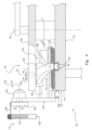
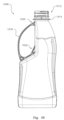
- a feature of the present machine 10, a preferred configuration of which is shown in Figure 3 is that motion through the machine of a non-symmetric injection moulded preform 12 as shown in Figure 1 , from its initial intake to its emergence as a stretch blow-moulded container 14 (as shown in Figure 2 ), is continuous.
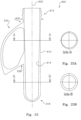
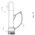
- the previously injection moulded polymer preform comprises a cylindrical elongate body 16 and neck 18.
- An integral handle 20 extends from a first junction point 22 just below the neck 18 to a second junction point 24 on the body 16 of the preform.
- the continuous, non-incrementing process of the machine 10 includes the transfer of preforms from a loading or pick off position 26 to a preheating stage 28, through the preheating stage and transfer to a stretch-blow moulding die 30 with subsequent removal of the blown container 14 from the die and removal from the machine.
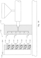
- the previously injection moulded preforms 12 are fed, for example from a hopper (not shown but as well understood in the industry) to slide under gravity down inclined rails 32 while supported by their necks 18.
- the inclined rails 32 comprise a pair of upper rails 32a between which the preforms are suspended by their necks 18, and a pair of lower rails 32b which constrain the handles 20 of the preforms approximately in line with the long axis of the rails.
- Preforms 12 with a handle roughly oriented pass one by one through an escapement 34 to be captured by a continuously rotating feeder wheel 36 which carries the preform between the feeder wheel and a short rail 40, in such a way that friction between the body 16 of the preform and the rail 40 induces rotation of the preform and its handle.
- the rotating handle collides with a stop 40a under the rail 40 forcing each handle into a rearward orientation with respect to the direction of travel, to arrive at a pick off position 26.
- a pair of opposing actuators located under the pick off position 26, simultaneously briefly close on, and then release, the preform handle 20 to fix its orientation relative the gripper 58 which, also at that instant engages with the neck 18 of the preform.
- the injection moulded preforms 12 are again fed onto inclined rails 32a, down which they slide under gravity supported by the flanges at the necks 18.
- the handles are loosely constrained between lower rails 32b, with the handles either in a "leading”, that is pointing in the direction of movement of the preforms as they progress down the incline, or "trailing", pointing rearwardly.
- an orientation mechanism 34A is located at a point along the rails 32 approaching the lower end of the rails.
- the mechanism includes two contra-rotating drive wheels 33 and 35, arranged at opposite sides of the rails 32, at a level coincident with the lowermost portion of the bodies of the preforms and below the lower rails 32b and the lowermost point of the handles.
- the axes of the wheels are normal to the slope of the inclined rails. Note only the lower rails 32b are shown in Figure 4A .
- the drive wheels 33 and 35 are separated by a gap 37 which is somewhat narrower than the diameter of the body 16 of the preforms.
- Each of the wheels 33 and 35 is provided with one or two tyres 39 of a sufficiently soft polymer material to allow a preform body 16 to pass through the gap but providing a degree of grip on the body.
- drive wheel 33 rotates in an anticlockwise direction while drive wheel 35 rotates in a clockwise direction.
- the combination of these two rotations has the effect of drawing a preform through the gap 37.
- the two drive wheels do not however rotate at the same rate, with, in the preferred arrangement shown in Figure 4A , drive wheel 35 rotating at a significantly lower rpm than that of guide wheel 33.
- a preferred ratio of rotation of drive wheel 33 to drive wheel 35 is of the order of 2:1.
- drive wheel 35 exerts a considerably greater grip on the body 16 of the preform so that it acts to rotate the preform in an anticlockwise direction as the preform passes through the gap 37 between the two drive wheels.
- a handle 20 of a preform which is in a leading position as the preform enters the gap 37, is rotated until it contacts the right hand lower rail 32b (as seen from above in Figure 4A ).
- a gap 40 is provide in the left hand lower rail.
- the escapement 34 controls the feeding of the handle oriented preforms to the feeder wheel 36 as described above, retaining the trailing orientation of the handles as induced by the mechanism 34A.
- a pair of opposing actuators located under the pick off position 26, simultaneously briefly close on, and then release, the preform handle 20 to fix its orientation relative the gripper 58 which, also at that instant engages with the neck 18 of the preform.
- Precise orientation of the handle throughout the stages of the machine is critical to the process of preheating where the orientation must align with the alignment of heat shields, and for correctly placing the preform and the handle into the stretch-blow-moulding die.
- injection moulded preforms 12 emerge one at a time from a bulk supply via, for example, a conveyor (not shown) to be deposited centrally onto a pair of contra-rotating, downward sloping rollers 11 and 13.
- the rollers 11 and 13 are so spaced as to allow the body 16 and handle 20 of each preform to drop through the gap between them but retain the wider diameter of the projecting collar below the neck 18 of the preform.
- the rollers 11 and 13 are mounted above a pair of spaced apart guide rails 15 and 17 (as best seen in Figure 4D ) similarly spaced as the gap between the rollers.
- the preforms drop to the level of main support rails 19 and 21, so that preforms are now retained between these main support rails by their collars.
- a combination of gravity and pressure from following preforms forces each preform against the upward outer ends of side by side, contra-rotating auger screws 23 and 25 located on either side of a median vertical plane between the support rails.
- the flutes 27 of the auger screws are sized so as to capture between them the necks 18 of the preforms.
- the pitch of the auger screws is such as to separate preforms while being driven in the downward direction by the screws' rotation.
- the main support rail 21 is provided at its underside with a friction strip 29 (as best seen in the enlargement inset of Figure 4D ).
- This friction strip 29 projects slightly into the gap between the main support rails 19 and 21 so that its inner edge engages with the body of a preform as it progresses between the augers. This friction contact urges rotation of the preform in an anticlockwise direction as seen from above.
- the rotation rate of the auger screws is such as to deliver a preform to the feeder wheel 36 in synchronization with the rotation of that wheel. Furthermore, the rotation of the auger screws provides pressure to ensure preforms proceed down the main support rails.
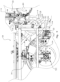
- a first rotating transfer system 42 is positioned adjacent the feeder wheel 36 with a continuously rotating carrier 44 of the first rotating transfer system 42 and the feeder wheel 36 contra-rotating one to the other.
- the rotating carrier 44 of the first rotating transfer system 42 includes, in this embodiment, four opposing support arms 46 extending radially from a fixed centre of rotation 48 to rotate about a vertical axis 50. Each end of the arms carries a first pick and place apparatus 52. Each first pick and place apparatus 52 includes a linear guide 54, a housing 56 which is rotatably mounted to the outer end of the support arm 46, enabling rotation of the housing 56 about a vertical axis 51.
- a two-fingered gripper 58 is mounted to a rotary actuator 60 supported by vertical plate 62 at an outer end of a free sliding element 64 of the linear guide 54.
- the gripper fingers 66 are centred on a gripper effective vertical axis 68, with the gripper able to be rotated about the horizontal axis 61 of the rotary actuator 60.
- a fixed horizontal cam plate 70 is mounted at a level below the rotating carrier 44 so that its centre is coincident with the vertical axis 50 of the rotating carrier.
- the perimeter edge 72 of the cam plate 70 forms an outer cam surface 74 and its upper surface 76 is provided with a cam channel 78 which is inboard of the perimeter edge 72 and the outer cam surface 74.
- the housing 56 of the linear guide 54 is provided with an outrigger arm 80 extending radially from the centre of rotation 82 of the linear guide 54.
- the outer end of the outrigger arm 80 supports a first cam follower 84 locating in the cam channel 78.
- the free sliding element 64 adapted to reciprocating linear motion in a horizontal plane, is provided with a second cam follower 86 with the free sliding element 64 biased by springs 88 to maintain contact between the second cam follower 86 and the outer cam surface 74.
- the cam channel 78 and outer cam surface 74 are arranged so that as a first pick and place apparatus 52 rotates past the preform pick off position 26, the rotation of the rotating carrier 44, combined with the loci of the first and second cam followers 84,86 causes the gripper 58 to be both reciprocatingly extended and retracted, and rotated relative the arm 46.
- the gripper motion is such that at the approach to the preform pick off position 26, the free sliding element 64 and thus the gripper 58 is extended followed by rotation of the linear guide 54 and gripper 58 in retrograde or negative direction relative to the direction of rotation of the rotating carrier 44.
- a preform 12 arrives at the pick off position 26 after its approximate orientation, so that the handle 20 of the preform is trailing but not yet fixed, the extending movement of the gripper 58 through the first cam follower 84 against the outer cam surface 74, brings the gripper effective axis 68 into coincidence with the central axis of the preform.
- a pair of opposing actuators located under the pick off position 26 simultaneously briefly close on, and then release, the preform handle 20 to fix its orientation relative the gripper 58 which, also at that instant engages with the neck 18 of the preform.
- the gripper 58 is then rotated positively to carry the preform 12 clear of the supporting short rail 40 and away from the pick off position 26.
- This combination of reciprocating rotation and extension and retraction of the gripper 58 compensates for the divergence of the loci of the supporting tooth formation 38 of the feeder wheel 36 and the rotating carrier 44 as they contra rotate one relative the other. It is by the means of the reciprocating rotation and retraction movements of the gripper through a combination of a rotating linear guide and the two cam loci that a smooth continuous transfer of preforms is possible between two rotating elements; that of the feeder wheel 36 and the rotating carrier 44.
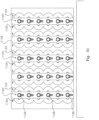
- the preheating transport system 90 is also in continuous movement and comprises a loop rail system 92 with proximate and distal rotating guide wheels 94 and 96 respectively at either end of the loop.
- a plurality of preform supporting mandrels 98 are adapted to move around the loop rail system 92, driven into motion around the straight sections of the loop by a drive chain (not shown) to which they are fixed and around the guide wheels 94,96 by nesting in niches 103 of the guide wheels.
- the mandrels 98 are continuously rotated about their vertical axes.
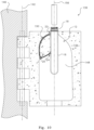
- a preform supporting mandrel 98 is provided with a heat shield 100 comprising a channel 102 rising from a cylindrical collar 104 in which the handle 20 is protected while the neck 18 is protected by its insertion into the cylindrical collar 104 of the mandrel.
- the patterns of the outer cam surface 74 and that of the cam channel 78 of the first rotating transfer system 42 as shown in Figure 5 differ from those at the approach to, and following the preform transfer to preheating position 106. This reflects the difference in movements required of a gripper 58 as it steers the preform into the position in which the vertical axis of the preform becomes aligned with that of the cylindrical collar 104 of the mandrel 98 and the handle 20 is aligned with the heat shield channel 102.
- the mandrels supported in the chain of the preheating transport system 90 travel along the first straight section 112, around the distal rotating guide wheel 96 and back along the second straight section 114 to arrive at a transfer-from-mandrel position 116. While traversing these straight sections, the mandrels are rotated about their vertical axes by a gear 105 of the mandrel engaging with chain 107 to evenly expose the bodies of the preforms to heat from the banks 110 of heating elements 109.
- the heating elements 109 are each arranged as a series of infra-red heating elements which are individually adjustable as to their proximity to the passing preforms.
- each mandrel 98 at both the transfer to preheating position 106 and at the transfer from mandrel position 116 is critical to allow the respective first and second transfer systems to insert and extract a preform handle from the channel of the mandrel's heat shield.
- These heat shield orientations with respect to the periphery of the proximate guide wheel 94 are not the same at these two positions so that the orientation of the mandrel and its heat shield need to be changed from that demanded at the handle extraction position to that required at the handle insertion position.
- each mandrel is provided with a guide carriage 98a fixed to the mandrel.
- cam followers 98b and 98c engage with guide channels to rotate the mandrel into the required orientation.
- the cam followers 98b and 98c follow cam channels of a cam plate above the proximate guide wheel to bring the orientation of the heat shield to that required at the transfer-to-preheating position 106.
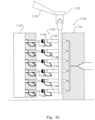
- a second rotating transfer system 118 operates to transfer preforms 12 from the preheating transport system 90 to a stretch blow moulding die assembly 120.
- the stretch blow moulding die assembly 120 comprises of four stretch blow moulding dies 30, two of which can be seen in the truncated view of the machine in Figure 9 .
- four radially disposed stretch blow moulding dies 30 rotate continuously about a common centre 122.
- the second rotating transfer system 118 is of similar configuration to that of the first rotating transfer system 42 described above. That is, it includes a cam plate 124, also provided with an inboard cam channel 126 and an outer cam surface 128 around its periphery.
- second rotating transfer system 118 includes two, rather than four, continuously rotating opposing radial arms 130, each of which carries a second pick and place apparatus 132.
- each includes a linear guide rotatably mounted to the respective outer end of the radial arm 130, with the free sliding element of the linear guide supporting a rotary actuator which, in turn supports a gripper.
- a first cam follower of an outrigger arm attached to the housing of the linear guide locates in the inboard cam channel 126, while a second cam follower of the free sliding element of the linear guide remains in contact with the outer cam surface 128 by means of a spring.
- Preforms still retained in preform supporting mandrels 98 arrive back at the rotating proximate guide wheel 94 of the preheating system and approach the transfer-from-mandrel position 116, and are rotated into the required orientation of the heat shield as explained above.
- the cylindrical plunger 108 of a mandrel 98 approaching the transfer-from-mandrel position 116 lifts the preform so that the neck is clear of the cylindrical collar 104 to allow the gripper of the second rotating transfer system 118 to engage the preform by the exposed neck 18.
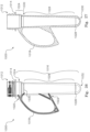
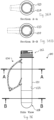
- Stretch blow moulding dies of the die assembly 120 are in the form of two die halves 136, one of which is shown in Figure 10 .
- Die halves 136 are hinged together about a vertical axis 142 in the manner of a bivalve, and with the hinge supported from a central structure 146 of the die assembly 130 in a typical arrangement for radial stretch-blow-moulding machines.
- the face surface 138 of the die half shown in Figure 10 has been shaded to highlight the die cavity 148 for the body 16 and integral handle 20 of the preform.
- the neck 18 which remains unaltered in the stretch-blow-moulding process, projects out of the die when closed.
- a radial arm 130 with a preform retained in the gripper of the second pick and place apparatus 132 also approaches the loading position.
- the movements of the second pick and place apparatus 132 has brought the gripper effective vertical axis and thus the vertical axis of the preform into coincidence with the axis 156 of the die (as defined by the centre of the preform body when held in the die) and with the handle oriented to lie in the vertical plane defined by the straight line 154.
- a third rotating transfer system 160 is located adjacent the stretch-blow-moulding die assembly 120, and is configured in similar manner to that of the first and second rotating transfer systems 42,132 described above.
- the third rotating transfer system 160 includes opposing radial arms 162 at the ends of each of which is a third pick and place assembly 164. It does not however include a rotary actuator since the container which emerges from the die remains in an upright position through the discharge process.
- movements of a gripper 166 is controlled by a combination of the rotation of the opposing radial arms 160, the linear movement of the free element of the linear guide and the two cam loci.
- the gripper of the pick and place is maneuvered into position to grasp the neck of the container.
- the die reaches the die unloading position, the die halves open and the gripper extracts the blown container 14 from the die 30.
- the third rotating transfer system 160 continuous to rotate, tanking the container 14 held by the gripper 166 into a discharge channel 172, with the base of the container passing over a guide rail 170.
- Guide rail 170 transitions from concentricity with the third rotating transfer system to concentricity with a rotating two-tiered outfeed wheel 172.
- the gripper 166 releases the neck and retracts.
- a scalloped indentation 172a of the rotating outfeed wheel captures the body of the container feeding it into a discharge channel 178.
- the base of the container receives cooling air from orifices 182 in guide rail 170, backpressure from accumulating containers in the discharge channel 172 force containers to drop into a container receiving bin 180.
- the operation of the machine 10 is under the control a programmable logic controller.
- the controller provides for fully adjustability of the parameters of the preheating elements and of the parameters of the stretch-blow-moulding dies. This includes setting differential temperature gradients allowing for a gradually increasing exposure to heat as preforms progress around the preheating transport system, and automatic adjustment of heating element temperatures for changing ambient temperatures.
- Control of the preheating is particularly critical in the present system because of the unique characteristics of the preform dictated by the integral handle of the preform.
- the preheating is thus designed to allow for lateral flow of material in the area between the two junction points of the handle while limiting longitudinal flow and extension during the stretching phase of the stretch-blow-moulding process. Instead, the manner in which heat is applied to the preform ensures that the bulk of polymer which forms the outer shell of the container of Figure 2 , is produced from that region of the preform below the lower junction point of the handle.
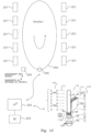
- Figure 12 is a schematic block diagram of control components associated with control of the heating and transport of the preforms usable with any of the above described embodiments.
- each bank 110 comprises a module 201.
- the modules 201 are arranged sequentially around the conveyer 202 as illustrated in figure 12 .
- a processor 203 in conjunction with memory 204 executes a program for control of the heating elements 109 of the modules 201.
- each element 109 of each module 201 is controlled individually by the processor 203.
- the elements 109 are controlled as a group based on height - so the top most elements 109 of the modules 201 are controlled to a predetermined temperature together whilst the next down in height elements 109B are also controlled together to a predetermined temperature - and so on down to elements 109G at the lowest level.
- processor 203 controls the speed of rotation of motor 205 in order to control the continuous speed of the preforms 16.
- a temperature sensor 206 in one form an infrared temperature sensor provides environment temperature sensing which is utilised by processor 203 to modulate the degree of heating of all elements 109 by a difference factor delta ( ⁇ ).
- the stretch-blow-moulding machine is especially developed for, and adapted to, the feeding and transportation of a non-symmetrical preform with integral handle and, ultimately the stretch-blow-moulding of that preform into a container with an integral handle.
- the preform according to the invention may take a number of different forms described below, although common to all are the neck portion 18 and the integral handle 20 as shown in Figure 1 .
- the preforms now to be described differ primarily in respect of the configuration of their internal surfaces, offering benefits of improved distribution of polymer material to the walls of the blown container as well as significant improvement in economy of manufacture due to reductions in the volume of polymer required.
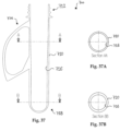
- a first configuration of a preform 310 as shown in Figure 13A includes a finished neck portion 312 and a tubular hollow body portion 314 extending from below the neck portion. Similar to preforms of the prior art, the outer surfaces of the body portion 314 are defined by diameters centred on a central vertical axis 316, so that the body portion 314 approximates a cylinder but with a decrease in diameters from the neck portion 312 to the closed end 318 of the preform.
- the internal surfaces of the preform 310 include surfaces of the hollow body portion 314 which are not concentric with the outer surfaces.
- cross sections of the internal surfaces of the preform 310 are circular and concentric in the neck portion 312 of the preform as indicated by the cross section A-A, but below the neck portion are of ovoid form as indicated by section B-B. All sections are however centred on the central longitudinal axis 316 of the body of the preform.
- the mandrel 322 around which the preform 310 is injection moulded comprises an upper region 324 of circular cross sections adapted to position and retain the mandrel in its correct position in an injection moulding cavity.
- a first preform-defining portion 326 of the mandrel extends from this upper region 324 to a depth equal to that of the neck portion 312 and is of circular cross section A-A as shown in Figure 4 to form the concentric walls of the neck portion.
- the ovoid portion 328 of the mandrel depends from the first portion 326, extending to the tip 330 of the mandrel.
- both the outer surfaces of the body portion 314 of the preform and the ovoid portion of the inside surfaces as defined by the mandrel 322, are tapering; that is, the diameters defining the external surface of the preform are decreasing from below the neck portion 312 to the bottom 318, while similarly, the major axis 344 and the minor axis 342 of the cross sections of the ovoid portion 328 also decrease accordingly.
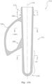
- the preform 310 further includes, as noted above, an integral handle 334 which forms a loop of material extending vertically from an upper junction 336 below the neck portion 312 to a lower junction 338 with the outer surface of the preform.
- the handle 334 is centred on and defines a central vertical plane 340 (lying in the plane of the paper) which contains the central longitudinal axis 316 of the preform.
- the mandrel 322, and thus the internal surfaces of the ovoid portion 328, are so oriented relative the handle 334, that major axis 344 of the ovoid cross section B-B lies in the central vertical plane 340.
- the wall thicknesses of the preform 310 in that portion 328 of the preform in which the inner surfaces are defined by the ovoid cross section varies from a maximum at opposite ends of the minor axes 342 of the ovoid cross section to minimum thicknesses at outer ends of the major axis 340.
- the ratio of maximum wall thickness to minimum wall thickness of the ovoid portion lies in the range of 2:1 and 2.2:1.
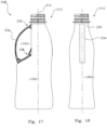
- the distribution of polymer in the preform according to the invention allows polymer walls of the preform in the region of maximum thickness to be biased predominantly towards the longer side walls 346 of a rectangular cross section blown container 348, while the polymer walls of the preform from the region of minimum thickness is predominantly distributed towards the shorter side walls 350 of the blown container such as shown in Figures 17 and 18 .
- the longer side walls 346 lie on either side of the central vertical plane 340 and thus the handle 334 so that the alignment of the major axis 344 with the vertical plane 340 ensures that the polymer from regions of maximum wall thickness are directed to those longer side walls.
- the preform of the first embodiment is produced by an injection moulding process as described earlier in this specification.
- the preform thus produced is reheated and blown on a continuously rotating, non-symmetric preform feed, stretch-blow-moulding machine as described earlier in this specification.
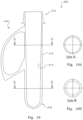
- the exterior surface 410 of the preform 400 is of substantially cylindrical form.
- it too includes an integrally injection moulded handle 434.
- the internal surfaces 414 of the preform are consistently circular in section as shown in the two sample cross sections Figure 17A and Figure 17B.
- there is a tapering of the internal surface 414 so that the wall sections, though concentric to the external surface, increase from a minimum thickness at the neck portion 412 of the preform to a maximum proximate its lower end 418.
- the preform of the second configuration is produced by an injection moulding process as described earlier in this specification.
- the preform thus produced is reheated and blown on a continuously rotating, non-symmetric preform feed, stretch-blow-moulding machine as described earlier in this specification.
- a preform 500 as shown in Figure 20 is formed to significantly reduce the volume of material required to produce the containers shown in Figures 17 and 18 .
- the preform 500 includes an injection moulded integral handle 534.
- the neck portion 512 is identical in its exterior and internal forms to that of the earlier configurations, there is a substantial reduction in the diameter of the substantially cylindrical portion of the body of the preform below the neck portion.
- the internal surfaces of the preform are consistently circular in section as shown in the two sample cross sections A and B of Figures 20A and 20B , but taper with the wall sections increasing from the minimum thickness obtaining in the neck portion and through the transition in diameters below the neck portion, to a maximum wall thickness proximate the lower end 518 of the preform.
- the outer surface 510 below the neck portion 512 also tapers towards the lower end 518.
- the preform of the third configuration is produced by an injection moulding process as described earlier in this specification.
- the preform thus produced is reheated and blown on a continuously rotating, non-symmetric preform feed, stretch-blow-moulding machine as described earlier in this specification.
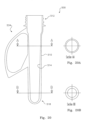
- this configuration of a preform 600 shares a number of characteristics with that of the first and second configurations above. It has, (as have all the preform configurations), an integral handle 634 as previously described, and, as in the first configuration above, the internal surfaces 614 of the preform are not consistently of circular section throughout the length of the preform. However, the external surfaces 610 of the perform are substantially cylindrical in form as in the second configuration.
- the external surfaces 610 are defined by circular cross sections
- the internal surface 614 varies from circular in cross section from the neck portion 612 down to section A-A in Figure 21A , to then transition to an ovoid section B-B as shown in Figure 21B , approaching the lower end 618.
- a feature of this particular configuration is that the wall thickness of the ovoid portion of the internal surface 614 of the perform at the ends of the major axes remains constant with the wall thicknesses of the concentric cross sections from section A-A and upwards, while there is a thickening of the walls increasing to maximum at the minor axis of the ovoid cross section.
- the preform of the fourth configuration is produced by an injection moulding process as described earlier in this specification. In preferred forms the preform thus produced is reheated and blown on a continuously rotating, non-symmetric preform feed, stretch-blow-moulding machine as described earlier in this specification.
- the preform of this configuration of a preform 700 shown in Figure 22 is similar to that of the fourth configuration above, but here, as shown in the cross section views A-A and B-B of Figures 22A and 22b , the wall thickness at the outer ends of the major axes of the ovoid cross section portion of the preform is not maintained equal with the wall thickness of at and below the neck portion 712. Rather the wall thickness gradually increases from below the neck portion towards the lower end 718 of the preform.
- preforms are typically injection moulded in multi-cavity dies 800 in which the cavities 820 in the die conform to the outer shape of the preform, including in the present cases, the shape of the integral handle.
- the mandrels 840 for forming the internal surfaces will also be of circular cross sections.
- the only requirement for positioning such a mandrel relative the injection-moulding cavity is its concentricity with the neck portion of the cavity.
- a mandrel for producing an internal surface of a perform which is wholly or partially non-circular in section may firstly require, a considerably more complex machining operation and, secondly it must be specifically oriented in the injection-moulding cavity.
- Mandrels for preforms with non-circular cross sections must be positioned within the cavities of an injection-moulding die 820, one half of which is shown in Figure 24 so that the major axes of the ovoid portion are aligned relative to a vertical central plane of the cavities.
- that vertical plane is the plane on which the handle of the preform is centred as set out above (in effect the face 842 of the die half).
- the orientation of the preform must be maintained in the cavity of the stretch-blow-moulding machine. That is, the vertical plane of the preform must coincide with a defined vertical plane of the container.
- the vertical plane of the preform is defined by the integral handle and is made coincident in the stretch-blow-moulding cavity with the central vertical plane of the blown container which again is central to the integral handle of the container.
- the die halves are brought together to close the die and the array of mandrels 840 driven into the cavities 820.
- the injection nozzle 848 is then advanced into the injection pocket 844 and molten polymer forced through the runner system 846 to fill the spaces between the external surfaces of the cavities 820 and the mandrels 840 to produce the preforms.
- the above description has focused on use of ovoid or offset cross sections to vary the wall thicknesses of at least a portion of a preform at any given cross section of that portion, it will be understood that such variation can be achieved with other non- concentric shaping of the mandrel.
- the ovoid cross sections are centred on the vertical axis of the preform, other material distribution effects may be achieved by an asymmetric positioning of these cross section.
- the preform of the fifth configuration is produced by an injection moulding process as described earlier in this specification.
- the preform thus produced is reheated and blown on a continuously rotating, non-symmetric preform feed, stretch-blow-moulding machine as described earlier in this specification.
- the preform 900 is provided with a wall thickness 911 in the region between the junction points 936 and 938 of the integrally injection-moulded handle 934 specifically to optimise control of the material in this region in the stretch-blow-moulding stage of producing a container from the preform.
- the external surface 910 of the preform is again substantially cylindrical.
- the internal surface of the preform is likewise formed of circular cross sections, but as can be seen in both the side sectioned view of Figure 13A and cross section AA of Figure 13A , the centres of a portion of the cross sections (typified by section A-A) do not lie on the central axis 930 of the body of the preform, but are offset towards the handle 934.
- the effect is to "thin" the wall thickness in the region between the junction points 936 and 938 of the handle. This is possible and desirable, because firstly there is a lesser volume of material required to form the container since there is no longitudinal stretching of this region and, secondly the thinning provides a significant cost saving in material.
- the preform of the sixth configuration is produced by an injection moulding process as described earlier in this specification.
- the preform thus produced is reheated and blown on a continuously rotating, non-symmetric preform feed, stretch-blow-moulding machine as described earlier in this specification.
- a preform 1000 for stretch-blow-moulding the container 1040 shown in Figure 28 is comprised of a neck portion 1012, a collar 1014 and a body 1016 extending from below the collar.
- the preform 1000 includes an integral handle 1018 joined to the body 1016 at first junction position 1020 just below the collar 1014 and a second junction position 1022 along the length of the body.
- the first cylindrical portion 1024 of the body extending below the collar 1014 is substantially of constant diameter, and in the region immediately below the collar, the diameter is substantially that of the finished container as can be seen in Figure 28 .
- this second portion 1026 of the body is not cylindrical but forms a portion of a narrow cone, with the base diameter 1030 of the cone, that is its largest diameter, significantly smaller than the diameter of the first cylindrical portion 1024.
- this large reduction in diameter and the tapering provide a first significant reduction in the volume of PET contained in the preform of the invention.
- the walls of the body 1016 of the preform 1000 vary considerably in thickness. While the wall thickness of the neck portion 1012 and the first portion 1024 below the collar 1014 are substantially of a constant thickness, that of the second portion 1026 varies from a relatively thin wall section at the base diameter 1030, to a maximum thickness proximate the tangent line 1028.
- the wall thickness of the bottom portion 1032 is further varied, being reduced from the maximum thickness at the tangent line 1028 to a minimum at the base of the bottom portion.
- these variation in wall thicknesses are designed to evenly distribute the volume of PET material to various areas of the walls of the stretch-blow-moulded container 1040 shown in Figure 28 , to an average thickness of approximately 0.5mm.
- the preform of the seventh configuration is produced by an injection moulding process as described earlier in this specification.
- the preform thus produced is reheated and blown on a continuously rotating, non-symmetric preform feed, stretch-blow-moulding machine as described earlier in this specification.
- preform having an integral handle with a flared portion thereby to impart an ergonomic aspect to the lifting of containers blown from the preform.
- a preform 2100 in a preferred form of the preform, includes a neck 2102, a body portion 2103 and a handle 2113.
- the neck 2102 has a threaded portion 2104 and a locating ring 2105.
- the preform is injection moulded from PET material in accordance with the teaching elsewhere in this specification.
- the handle in its configuration as injection moulded in its preform state, remains unaltered by the stretch blow-moulding process forming the resulting container from the continuous blow moulding process described elsewhere in this specification.
- the preform 2100 shown in Figures 33 to 35 is fed into a blow moulding machine such for example as the machine 10 shown schematically in Figure 3 , and blow moulded according to bi-axial orientation blow moulding techniques.
- a blow moulding machine such for example as the machine 10 shown schematically in Figure 3
- the neck 2102 is held in a mandrel 322, as shown in Figures 14 of a transport system of the machine 10 in such a way as to prevent its expansion in the stretch blow-moulding die 30.
- the loop of orientable material forming the handle 2113 has a generally uniform cross section from proximate the lower connection region 2116 to a gradually widening cross section 2124 approaching the upper connection region 2115 with the cross section reaching and maintaining a maximum width proximate the upper connection region 2115 as can be seen in Figures 34 and 35 .
- integrally moulded first, second and third strengthening elements 2135, 2136 and 2137 are provided respectively at each of the upper connection region 2115, the lower connection region 2116 and at the junction between the straight section 2118 and the arcuate section 2120 of the handle 2113.
- the first strengthening element 2135 at the upper connection region 2115 comprises a curved strengthening element conforming generally in width and in cross section to the width and cross section of the widened portion 2124 of the handle proximate the upper connection region.
- the curved strengthening element extends from a first separate connection region 2140 on the body portion 2103 of the preform (and on the blown container) below the upper connection region 2115 and merges with the loop of orientable material proximate a first end 2141 of the maximum width of the handle.
- the second strengthening element 2136 at the lower connection region 2116 of the handle comprises a straight strengthening element conforming generally in width and cross section with the width and cross section of the straight section 2118.
- the straight strengthening element extends from a second separate connection region 2142 above the lower connection region 2116 of the straight section of the handle, to merge with the straight section of the handle proximate the lower connection region.
- the third strengthening element 2137 at the junction of the straight section 2118 and the arcuate section 2120 of the handle comprises a further curved strengthening element conforming generally in width and cross section with the width and cross section of the handle of both the straight section 2118 and the arcuate section 2120 adjacent the junction. Respective outer ends of this further curved element merge with each of the straight 2118 and arcuate 2120 sections.
- the width of the first strengthening element 2135 is the same as that of the maximum width of the widened part 2124 of the handle proximate the upper connection region 2115. It is this increased width of the first strengthening element 2135 which provides for a larger area for distributing the load of a container over the index finger of a hand (not shown) lifting the container, while the curvature of the first strengthening element is selected to fit comfortably on the average index finger of a human hand.
- each strengthening element 2135, 2136 and 2137 includes a web of orientable material within boundaries formed respectively between the body portion 2112 of the preform and the first and second strengthening elements 2135 and 2136, and between the third strengthening element 2137 and the straight and arcuate sections 2118 and 2120.
- Each web of orientable material is aligned with and extends equally in both directions from the central line 2132 of handle.
- the preform of the eighth configuration is produced by an injection moulding process as described earlier in this specification.
- the preform thus produced is reheated and blown on a continuously rotating, non-symmetric preform feed, stretch-blow-moulding machine as described earlier in this specification.
- FIG 36 there is illustrated a ninth configuration of the preform showing alternative cross section arrangements for the purpose of reducing volume of the preform.
- like components are numbered as for the fourth configuration with reference to figure 21 .
- the cross section wall profile as shown in section AA and section BB is rotated 90 degrees as compared with the wall profile of figure 21 .
- the preform of the ninth configuration is produced by an injection moulding process as described earlier in this specification.
- the preform thus produced is reheated and blown on a continuously rotating, non-symmetric preform feed, stretch-blow-moulding machine as described earlier in this specification.
- FIG 37 there is illustrated a tenth configuration of the preform showing alternative cross section arrangements for the purpose of reducing volume of the preform.
- like components are numbered as for the fifth configuration with reference to figure 22 .
- the cross section wall profile as shown in section AA and section BB is rotated 90 degrees as compared with the wall profile of figure 22 .
- the preform of the tenth configuration is produced by an injection moulding process as described earlier in this specification.
- the preform thus produced is reheated and blown on a continuously rotating, non-symmetric preform feed, stretch-blow-moulding machine as described earlier in this specification.
- the integral handle of the preform is not substantially deformed or substantially changed in shape during the stretch-blow-moulding process but substantially retains its as-injection-moulded shape.
- the blow-moulding cavity shown in Figure 10 includes a recess specifically shaped to the form of the handle as injection moulded. This it will be understood is also a primary function of the heat shield to protect the handle from heat which could cause distortion of the handle while the preform is transported around the preheating stage of the machine.
- the bodies of the preforms below the neck are formed in cavities in the "hot", fixed section of the injection moulding die, with the threaded neck portions formed in opposing half cavities carried on the face of the moving die section.
- the bodies of the preforms are drawn out of their cavities by the necks which, at this first opening stage, are retained in the still closed opposing half cavities and move with the opening die section.
- the opposing half cavities now part to release the necks and a stripper plate is activated to force the preforms off the cores (which are fixed to the moving die section).
- preforms 1100 with handles 1112 only that section 1114 below the handle can be formed in cavities 1116 in the heated, fixed section 1118 of the die 1120, with the neck 1122 and handle 1112 formed in much longer and more complex opposing half cavities 1124 carried on the moving die section 1126.
- the cores 1128 to form the internal shape of the preforms 1100 are fixed to the moving die section 1126 and are located on the common axis of the cavities 1116 in the heated fixed side of the die and the opposing half cavities.
- a robot 1130 (only a portion of the arm of which is shown in Figure 32 ) is employed in the demoulding of the preforms 1100.
- the robot arm end effector 1132 is fitted with an array 1134 of vacuum cups 1136, equal in number and spaced according to the number and spacing of the cavities in the injection moulding die as shown in Figure 31 .
- this array 1134 of vacuum cups is poised above (or to the side of) the injection moulding die 1120 and as soon as the die opens sufficiently to allow insertion of the array, the robot brings the array into registered position between the parted sections 1118 and 1126 of the die, and advances the vacuum cups 1136 to fit over the lower ends of the preforms.
- the handles remain aligned in their as-moulded orientation to prevent rotation of the handles into positions at which they may be caught on edges of the opposing cavity halves.
- the vacuum cups are provided with a slot or channel 138 at their outer ends which slides around the lower end of the handle. By this means also a larger portion of the preform is covered by the vacuum cup. Vacuum is now applied to the cups 1136 and the robot retracts the array 1134, and the preforms 1100 now secured by vacuum pressure in the cups, to draw the preforms off the cores .
- the array of vacuum cups and retained preforms are withdrawn from between the heated fixed section 1118 and the moving side 1126 of the die, and rotated so that the axes of the preforms are in a substantially vertical orientation. Vacuum pressure is then cut allowing the preforms to fall from the vacuum cups into a receiving bin.
- the advantage of the use of vacuum in the demoulding process rather than a conventional stripper plate, is that the application of vacuum aids significantly to the cooling of the preforms, thus allowing their extraction at an earlier point in the mould cycle and shortening that cycle.
- This is particularly beneficial for the preforms of the present invention in which the end below the handle, being the last part of the preform to be formed (injection proceeding from the tip of the closed end of the preform), is at the highest temperature when the die opens.
- the slot or channel which accommodates the lower part of the handle provides for a greater portion of the preform to be subjected to the cooling provided by air flow into the suction cups when vacuum is applied just before suction cups fully envelop the lower and mid portions of the preforms.
- the cooling proceeds further as the robot draws the array of vacuum cups and preforms away from the die and over a receiving bin.
- the array is then rotated from the initial as-removed from the die position, that is with the axes of the preforms horizontal, to the vertical allowing the preforms to fall out of the cups when vacuum pressure is cut, and into the receiving bin.
- the preforms of the above described configurations provide for the stretch-blow-moulding of a container in the stretch-blow-moulding machine, which is equal in capacity to that of the container of the prior art shown in Figure 25 , but with a significant reduction in the volume of PET and conferring an optimum distribution of material from the preform to form the containers shown in Figures 17 and 18 .
- the preforms provide for a considerable reduction in raw material costs in the production of PET containers with integral handle.
Landscapes
- Engineering & Computer Science (AREA)
- Mechanical Engineering (AREA)
- Manufacturing & Machinery (AREA)
- Physics & Mathematics (AREA)
- Thermal Sciences (AREA)
- Robotics (AREA)
- Ceramic Engineering (AREA)
- Blow-Moulding Or Thermoforming Of Plastics Or The Like (AREA)
Priority Applications (1)
| Application Number | Priority Date | Filing Date | Title |
|---|---|---|---|
| EP25157099.0A EP4578630A1 (en) | 2017-09-21 | 2018-09-20 | Continuous blow moulding machine, preforms, system and process |
Applications Claiming Priority (6)
| Application Number | Priority Date | Filing Date | Title |
|---|---|---|---|
| AU2017903839A AU2017903839A0 (en) | 2017-09-21 | Blow Moulding Machine, System and Process | |
| AU2017904831A AU2017904831A0 (en) | 2017-11-30 | Reduced Volume PET Integral Handle Preform and Container Blown Therefrom | |
| AU2018900795A AU2018900795A0 (en) | 2018-03-09 | Blow Moulding Machine, System and Process | |
| AU2018900977A AU2018900977A0 (en) | 2018-03-23 | Asymmetric preform and container blown therefrom | |
| AU2018901184A AU2018901184A0 (en) | 2018-04-10 | Continuous blow moulding machine, preforms, system and process | |
| PCT/AU2018/051030 WO2019056063A1 (en) | 2017-09-21 | 2018-09-20 | MACHINE, PREFORMS, SYSTEM AND METHOD FOR CONTINUOUS BLOW MOLDING |
Related Child Applications (1)
| Application Number | Title | Priority Date | Filing Date |
|---|---|---|---|
| EP25157099.0A Division EP4578630A1 (en) | 2017-09-21 | 2018-09-20 | Continuous blow moulding machine, preforms, system and process |
Publications (4)
| Publication Number | Publication Date |
|---|---|
| EP3684586A1 EP3684586A1 (en) | 2020-07-29 |
| EP3684586A4 EP3684586A4 (en) | 2021-05-26 |
| EP3684586C0 EP3684586C0 (en) | 2025-02-12 |
| EP3684586B1 true EP3684586B1 (en) | 2025-02-12 |
Family
ID=65809544
Family Applications (2)
| Application Number | Title | Priority Date | Filing Date |
|---|---|---|---|
| EP18859426.1A Active EP3684586B1 (en) | 2017-09-21 | 2018-09-20 | Continuous blow moulding method |
| EP25157099.0A Pending EP4578630A1 (en) | 2017-09-21 | 2018-09-20 | Continuous blow moulding machine, preforms, system and process |
Family Applications After (1)
| Application Number | Title | Priority Date | Filing Date |
|---|---|---|---|
| EP25157099.0A Pending EP4578630A1 (en) | 2017-09-21 | 2018-09-20 | Continuous blow moulding machine, preforms, system and process |
Country Status (14)
| Country | Link |
|---|---|
| US (3) | US11104055B2 (enExample) |
| EP (2) | EP3684586B1 (enExample) |
| JP (1) | JP7426934B2 (enExample) |
| KR (2) | KR20240046601A (enExample) |
| CN (2) | CN115519771A (enExample) |
| AU (1) | AU2018337669B2 (enExample) |
| CA (1) | CA3076390A1 (enExample) |
| MA (1) | MA50193A (enExample) |
| MX (1) | MX2020003057A (enExample) |
| MY (1) | MY205042A (enExample) |
| SG (1) | SG11202002502WA (enExample) |
| TW (1) | TWI833707B (enExample) |
| WO (1) | WO2019056063A1 (enExample) |
| ZA (1) | ZA202104807B (enExample) |
Families Citing this family (13)
| Publication number | Priority date | Publication date | Assignee | Title |
|---|---|---|---|---|
| TWI833707B (zh) * | 2017-09-21 | 2024-03-01 | 澳大利亞商英特葛雷特塑膠公司 | 連續旋轉、非對稱預形成物進給之吹模成型機器及相關之方法 |
| EP3717201B1 (en) * | 2017-11-30 | 2025-04-02 | Integrated Plastics Pty Limited | Preforms for stretch-blow-moulding containers and continuous blow moulding machine producing the containers |
| AU201811807S (en) * | 2018-03-23 | 2018-04-23 | Integrated Plastics Pty Ltd | Tapered Integral Handle Pre-form |
| USD1036260S1 (en) * | 2018-12-13 | 2024-07-23 | Integrated Plastics Pty Limited | Pre-form |
| KR102260061B1 (ko) * | 2020-06-11 | 2021-06-04 | 형제프라콘(주) | 손잡이를 갖춘 페트병 제조방법과 이에 따른 제조장치 및 이에 의해 제조된 페트병 |
| JP7527467B2 (ja) * | 2020-09-17 | 2024-08-02 | 広州達意隆包装機械股▲フン▼有限公司 | 取手付きpetボトルプリフォーム熱処理設備 |
| KR102435305B1 (ko) | 2020-09-25 | 2022-08-23 | (주)진성종합테크 | 프리폼 정렬공급장치 |
| US12492041B2 (en) | 2021-03-26 | 2025-12-09 | Integrated Plastics Pty Limited | Continuous stretch blow moulding system applied to specified integral handle pet preform and container structures |
| US20240253293A1 (en) * | 2021-03-26 | 2024-08-01 | Integrated Plastics Pty Limited | Continuous stretch blow moulding system applied to specified integral handle pet preform and container structures |
| CN115743998A (zh) * | 2022-09-26 | 2023-03-07 | 江汉大学 | 大型换热器管芯导向安装及输送机构、控制方法及系统 |
| CN116119321B (zh) * | 2022-12-27 | 2023-08-01 | 上海裕隆生物科技有限公司 | 一种核酸荧光检测设备 |
| WO2025208188A1 (pt) * | 2024-03-30 | 2025-10-09 | Gripmaster Indústria, Comércio E Soluções Em Borracha | 3s dispositivo atuador para injeção de materiais em pneus e similares |
| CN119744221A (zh) * | 2024-05-26 | 2025-04-01 | 吴永鹏 | 一种双层真空的塑料瓶 |
Citations (1)
| Publication number | Priority date | Publication date | Assignee | Title |
|---|---|---|---|---|
| US20150044620A1 (en) * | 2006-03-09 | 2015-02-12 | B & R Industries, Pty. Ltd | Pet blow moulding machines |
Family Cites Families (26)
| Publication number | Priority date | Publication date | Assignee | Title |
|---|---|---|---|---|
| US4035463A (en) * | 1968-01-16 | 1977-07-12 | Heidenreich & Harbeck | Method of making hollow articles, especially bottles, of thermoplastics |
| AU7923382A (en) * | 1981-02-23 | 1982-09-02 | Continental Group Inc., The | Blow moulding pre-form |
| FR2709264B1 (fr) | 1993-08-26 | 1995-10-27 | Sidel Sa | Installation de fabrication de récipients par soufflage de préformes en matière plastique. |
| FR2713195B1 (fr) * | 1993-12-02 | 1996-01-12 | Serac Sa | Installation de conditionnement pour des récipients ayant une base présentant au moins un grand côté et un petit côté. |
| WO1999012715A1 (en) * | 1997-09-09 | 1999-03-18 | Bealetec Pty Ltd | Container with integral handle, preform and method of manufacture |
| JP3391238B2 (ja) * | 1997-10-17 | 2003-03-31 | 東洋製罐株式会社 | ブロー成形装置 |
| FR2802191B1 (fr) * | 1999-12-13 | 2002-03-01 | Sidel Sa | Dispositif de convoyage d'entites discretes comportant un bras de transfert perfectionne et installation de soufflage de recipients munie d'un tel dispositif |
| DE10040081A1 (de) | 2000-08-16 | 2002-03-07 | Bosch Gmbh Robert | Kettenglied, insbesondere einer kurvengängigen Förderkette |
| CN2517673Y (zh) * | 2001-09-28 | 2002-10-23 | 常州集成塑料有限公司 | 防静电导电集装袋 |
| JP4285727B2 (ja) * | 2002-11-08 | 2009-06-24 | 株式会社フロンティア | ブロー成形装置の移送機構 |
| FR2867171B1 (fr) * | 2004-03-05 | 2007-06-08 | Sidel Sa | Dispositif de convoyage comportant un bras de transfert ameliore |
| FR2917390B1 (fr) * | 2007-06-13 | 2010-01-15 | Ads | Chaine de transfert pour preformes a poignee |
| EP2002961B1 (fr) | 2007-06-13 | 2010-02-10 | ADS (Société anonyme) | Chaîne de transfert pour préformes à poignée |
| US8524143B2 (en) | 2009-09-16 | 2013-09-03 | Dt Inventions, Llc | Method for forming a container from bi-axially orientable plastics material and having an integral handle |
| DE102010027907A1 (de) | 2010-04-19 | 2011-10-20 | Krones Ag | Vorrichtung und Verfahren zum Handhaben eines Behälterproduktes |
| DE102010035496A1 (de) | 2010-08-25 | 2012-03-01 | Krones Aktiengesellschaft | Fördervorrichtung zum Fördern von Vorformlingen |
| CN101961914B (zh) * | 2010-10-21 | 2013-06-19 | 张士生 | 一种吹瓶机的瓶坯输送链 |
| ES2735096T3 (es) * | 2011-08-22 | 2019-12-16 | Nissei Asb Machine Co Ltd | Procedimiento de moldeo por soplado para recipiente con asa |
| EP2765325B1 (en) | 2013-02-08 | 2018-04-04 | ContiTech USA, Inc. | Air spring with stepper motor driven pneumatic valve |
| CN105451965B (zh) * | 2013-08-21 | 2018-04-24 | 日精Asb机械株式会社 | 制造带把手容器的方法、制造带把手容器的装置及带把手容器 |
| USD746142S1 (en) | 2013-10-04 | 2015-12-29 | Dt Inventions | Bottle preform |
| US9505163B2 (en) | 2014-01-21 | 2016-11-29 | Dt Inventions, Llc | Manufacturing method and device for a container with an integral handle |
| CN106414028B (zh) * | 2014-06-18 | 2019-04-09 | 萨克米伊莫拉有限公司 | 用于供给预成型件的系统 |
| CN204505798U (zh) * | 2014-12-15 | 2015-07-29 | 湖南鑫高自动化设备有限公司 | 一种塑料瓶注拉吹成型装置 |
| US10919207B2 (en) * | 2017-09-21 | 2021-02-16 | Integrated Plastics Pty Limited | Blow moulding machine, preforms, system and process |
| TWI833707B (zh) * | 2017-09-21 | 2024-03-01 | 澳大利亞商英特葛雷特塑膠公司 | 連續旋轉、非對稱預形成物進給之吹模成型機器及相關之方法 |
-
2018
- 2018-09-14 TW TW107132460A patent/TWI833707B/zh active
- 2018-09-20 CA CA3076390A patent/CA3076390A1/en active Pending
- 2018-09-20 MA MA050193A patent/MA50193A/fr unknown
- 2018-09-20 EP EP18859426.1A patent/EP3684586B1/en active Active
- 2018-09-20 KR KR1020247009633A patent/KR20240046601A/ko active Pending
- 2018-09-20 KR KR1020207010601A patent/KR20200055033A/ko not_active Ceased
- 2018-09-20 WO PCT/AU2018/051030 patent/WO2019056063A1/en not_active Ceased
- 2018-09-20 US US16/649,580 patent/US11104055B2/en active Active
- 2018-09-20 EP EP25157099.0A patent/EP4578630A1/en active Pending
- 2018-09-20 CN CN202210873861.5A patent/CN115519771A/zh active Pending
- 2018-09-20 SG SG11202002502WA patent/SG11202002502WA/en unknown
- 2018-09-20 JP JP2020537811A patent/JP7426934B2/ja active Active
- 2018-09-20 CN CN201880075586.4A patent/CN111372750B/zh active Active
- 2018-09-20 AU AU2018337669A patent/AU2018337669B2/en active Active
- 2018-09-20 MY MYPI2020001455A patent/MY205042A/en unknown
- 2018-09-20 MX MX2020003057A patent/MX2020003057A/es unknown
-
2021
- 2021-07-09 ZA ZA2021/04807A patent/ZA202104807B/en unknown
- 2021-08-27 US US17/458,698 patent/US11660802B2/en active Active
-
2023
- 2023-05-29 US US18/325,037 patent/US12434423B2/en active Active
Patent Citations (1)
| Publication number | Priority date | Publication date | Assignee | Title |
|---|---|---|---|---|
| US20150044620A1 (en) * | 2006-03-09 | 2015-02-12 | B & R Industries, Pty. Ltd | Pet blow moulding machines |
Also Published As
| Publication number | Publication date |
|---|---|
| TWI833707B (zh) | 2024-03-01 |
| CN115519771A (zh) | 2022-12-27 |
| JP2020535047A (ja) | 2020-12-03 |
| KR20200055033A (ko) | 2020-05-20 |
| US12434423B2 (en) | 2025-10-07 |
| US11660802B2 (en) | 2023-05-30 |
| EP4578630A1 (en) | 2025-07-02 |
| ZA202104807B (en) | 2025-11-26 |
| CA3076390A1 (en) | 2019-03-28 |
| AU2018337669B2 (en) | 2024-07-04 |
| WO2019056063A1 (en) | 2019-03-28 |
| KR20240046601A (ko) | 2024-04-09 |
| MY205042A (en) | 2024-09-29 |
| EP3684586C0 (en) | 2025-02-12 |
| EP3684586A4 (en) | 2021-05-26 |
| TW201919848A (zh) | 2019-06-01 |
| AU2018337669A1 (en) | 2020-04-16 |
| MA50193A (fr) | 2021-05-26 |
| SG11202002502WA (en) | 2020-04-29 |
| EP3684586A1 (en) | 2020-07-29 |
| MX2020003057A (es) | 2020-08-13 |
| JP7426934B2 (ja) | 2024-02-02 |
| US20230302710A1 (en) | 2023-09-28 |
| CN111372750A (zh) | 2020-07-03 |
| US20200254676A1 (en) | 2020-08-13 |
| US11104055B2 (en) | 2021-08-31 |
| US20210387398A1 (en) | 2021-12-16 |
| WO2019056063A4 (en) | 2019-04-25 |
| CN111372750B (zh) | 2022-07-22 |
Similar Documents
| Publication | Publication Date | Title |
|---|---|---|
| US12434423B2 (en) | Continuous blow moulding machine, preforms, system and process | |
| EP3717201B1 (en) | Preforms for stretch-blow-moulding containers and continuous blow moulding machine producing the containers | |
| AU2018204788B2 (en) | Blow moulding machine, preforms, system and process | |
| KR102360282B1 (ko) | 인체 공학적 일체형 손잡이 조립체 | |
| US12492041B2 (en) | Continuous stretch blow moulding system applied to specified integral handle pet preform and container structures | |
| US20240253293A1 (en) | Continuous stretch blow moulding system applied to specified integral handle pet preform and container structures | |
| EP4337440A1 (en) | Continuous stretch blow moulding system applied to specified integral handle pet preform and container structures | |
| JP5867562B1 (ja) | 押出ブロー成形機 | |
| EP3041658A1 (en) | Post-molding cooling apparatus for preforms made of thermoplastic material |
Legal Events
| Date | Code | Title | Description |
|---|---|---|---|
| STAA | Information on the status of an ep patent application or granted ep patent |
Free format text: STATUS: THE INTERNATIONAL PUBLICATION HAS BEEN MADE |
|
| PUAI | Public reference made under article 153(3) epc to a published international application that has entered the european phase |
Free format text: ORIGINAL CODE: 0009012 |
|
| STAA | Information on the status of an ep patent application or granted ep patent |
Free format text: STATUS: REQUEST FOR EXAMINATION WAS MADE |
|
| 17P | Request for examination filed |
Effective date: 20200406 |
|
| AK | Designated contracting states |
Kind code of ref document: A1 Designated state(s): AL AT BE BG CH CY CZ DE DK EE ES FI FR GB GR HR HU IE IS IT LI LT LU LV MC MK MT NL NO PL PT RO RS SE SI SK SM TR |
|
| AX | Request for extension of the european patent |
Extension state: BA ME |
|
| RIN1 | Information on inventor provided before grant (corrected) |
Inventor name: KIM, HO-SEON Inventor name: MELLEN, NICK |
|
| DAX | Request for extension of the european patent (deleted) | ||
| RAV | Requested validation state of the european patent: fee paid |
Extension state: MA Effective date: 20200406 Extension state: TN Effective date: 20200406 |
|
| A4 | Supplementary search report drawn up and despatched |
Effective date: 20210423 |
|
| RIC1 | Information provided on ipc code assigned before grant |
Ipc: B29C 49/64 20060101AFI20210419BHEP Ipc: B29C 49/42 20060101ALI20210419BHEP Ipc: B29L 31/00 20060101ALN20210419BHEP Ipc: B29C 49/10 20060101ALN20210419BHEP Ipc: B29C 49/28 20060101ALN20210419BHEP Ipc: B29C 49/36 20060101ALN20210419BHEP Ipc: B29C 31/08 20060101ALN20210419BHEP Ipc: B65G 47/24 20060101ALN20210419BHEP Ipc: B65G 47/84 20060101ALN20210419BHEP |
|
| STAA | Information on the status of an ep patent application or granted ep patent |
Free format text: STATUS: EXAMINATION IS IN PROGRESS |
|
| 17Q | First examination report despatched |
Effective date: 20220318 |
|
| REG | Reference to a national code |
Ref country code: DE Ref legal event code: R079 Free format text: PREVIOUS MAIN CLASS: B29C0049420000 Ipc: B29C0049640000 Ref country code: DE Ref legal event code: R079 Ref document number: 602018079162 Country of ref document: DE Free format text: PREVIOUS MAIN CLASS: B29C0049420000 Ipc: B29C0049640000 |
|
| GRAP | Despatch of communication of intention to grant a patent |
Free format text: ORIGINAL CODE: EPIDOSNIGR1 |
|
| STAA | Information on the status of an ep patent application or granted ep patent |
Free format text: STATUS: GRANT OF PATENT IS INTENDED |
|
| RIC1 | Information provided on ipc code assigned before grant |
Ipc: B65G 47/84 20060101ALN20240410BHEP Ipc: B65G 47/24 20060101ALN20240410BHEP Ipc: B29C 31/08 20060101ALN20240410BHEP Ipc: B29C 49/36 20060101ALN20240410BHEP Ipc: B29C 49/28 20060101ALN20240410BHEP Ipc: B29C 49/10 20060101ALN20240410BHEP Ipc: B29L 31/00 20060101ALN20240410BHEP Ipc: B29C 49/42 20060101ALI20240410BHEP Ipc: B29C 49/64 20060101AFI20240410BHEP |
|
| INTG | Intention to grant announced |
Effective date: 20240424 |
|
| GRAJ | Information related to disapproval of communication of intention to grant by the applicant or resumption of examination proceedings by the epo deleted |
Free format text: ORIGINAL CODE: EPIDOSDIGR1 |
|
| STAA | Information on the status of an ep patent application or granted ep patent |
Free format text: STATUS: EXAMINATION IS IN PROGRESS |
|
| GRAP | Despatch of communication of intention to grant a patent |
Free format text: ORIGINAL CODE: EPIDOSNIGR1 |
|
| STAA | Information on the status of an ep patent application or granted ep patent |
Free format text: STATUS: GRANT OF PATENT IS INTENDED |
|
| INTC | Intention to grant announced (deleted) | ||
| RIC1 | Information provided on ipc code assigned before grant |
Ipc: B65G 47/84 20060101ALN20240827BHEP Ipc: B65G 47/24 20060101ALN20240827BHEP Ipc: B29C 31/08 20060101ALN20240827BHEP Ipc: B29C 49/36 20060101ALN20240827BHEP Ipc: B29C 49/28 20060101ALN20240827BHEP Ipc: B29C 49/10 20060101ALN20240827BHEP Ipc: B29L 31/00 20060101ALN20240827BHEP Ipc: B29C 49/42 20060101ALI20240827BHEP Ipc: B29C 49/64 20060101AFI20240827BHEP |
|
| INTG | Intention to grant announced |
Effective date: 20240904 |
|
| GRAS | Grant fee paid |
Free format text: ORIGINAL CODE: EPIDOSNIGR3 |
|
| GRAA | (expected) grant |
Free format text: ORIGINAL CODE: 0009210 |
|
| STAA | Information on the status of an ep patent application or granted ep patent |
Free format text: STATUS: THE PATENT HAS BEEN GRANTED |
|
| AK | Designated contracting states |
Kind code of ref document: B1 Designated state(s): AL AT BE BG CH CY CZ DE DK EE ES FI FR GB GR HR HU IE IS IT LI LT LU LV MC MK MT NL NO PL PT RO RS SE SI SK SM TR |
|
| REG | Reference to a national code |
Ref country code: GB Ref legal event code: FG4D |
|
| REG | Reference to a national code |
Ref country code: CH Ref legal event code: EP |
|
| REG | Reference to a national code |
Ref country code: DE Ref legal event code: R096 Ref document number: 602018079162 Country of ref document: DE |
|
| REG | Reference to a national code |
Ref country code: IE Ref legal event code: FG4D |
|
| U01 | Request for unitary effect filed |
Effective date: 20250311 |
|
| U07 | Unitary effect registered |
Designated state(s): AT BE BG DE DK EE FI FR IT LT LU LV MT NL PT RO SE SI Effective date: 20250423 |
|
| PG25 | Lapsed in a contracting state [announced via postgrant information from national office to epo] |
Ref country code: RS Free format text: LAPSE BECAUSE OF FAILURE TO SUBMIT A TRANSLATION OF THE DESCRIPTION OR TO PAY THE FEE WITHIN THE PRESCRIBED TIME-LIMIT Effective date: 20250512 |
|
| PG25 | Lapsed in a contracting state [announced via postgrant information from national office to epo] |
Ref country code: PL Free format text: LAPSE BECAUSE OF FAILURE TO SUBMIT A TRANSLATION OF THE DESCRIPTION OR TO PAY THE FEE WITHIN THE PRESCRIBED TIME-LIMIT Effective date: 20250212 |
|
| PG25 | Lapsed in a contracting state [announced via postgrant information from national office to epo] |
Ref country code: ES Free format text: LAPSE BECAUSE OF FAILURE TO SUBMIT A TRANSLATION OF THE DESCRIPTION OR TO PAY THE FEE WITHIN THE PRESCRIBED TIME-LIMIT Effective date: 20250212 |
|
| PG25 | Lapsed in a contracting state [announced via postgrant information from national office to epo] |
Ref country code: IS Free format text: LAPSE BECAUSE OF FAILURE TO SUBMIT A TRANSLATION OF THE DESCRIPTION OR TO PAY THE FEE WITHIN THE PRESCRIBED TIME-LIMIT Effective date: 20250612 Ref country code: NO Free format text: LAPSE BECAUSE OF FAILURE TO SUBMIT A TRANSLATION OF THE DESCRIPTION OR TO PAY THE FEE WITHIN THE PRESCRIBED TIME-LIMIT Effective date: 20250512 |
|
| PG25 | Lapsed in a contracting state [announced via postgrant information from national office to epo] |
Ref country code: HR Free format text: LAPSE BECAUSE OF FAILURE TO SUBMIT A TRANSLATION OF THE DESCRIPTION OR TO PAY THE FEE WITHIN THE PRESCRIBED TIME-LIMIT Effective date: 20250212 |
|
| PG25 | Lapsed in a contracting state [announced via postgrant information from national office to epo] |
Ref country code: GR Free format text: LAPSE BECAUSE OF FAILURE TO SUBMIT A TRANSLATION OF THE DESCRIPTION OR TO PAY THE FEE WITHIN THE PRESCRIBED TIME-LIMIT Effective date: 20250513 |
|
| PG25 | Lapsed in a contracting state [announced via postgrant information from national office to epo] |
Ref country code: SM Free format text: LAPSE BECAUSE OF FAILURE TO SUBMIT A TRANSLATION OF THE DESCRIPTION OR TO PAY THE FEE WITHIN THE PRESCRIBED TIME-LIMIT Effective date: 20250212 |
|
| PG25 | Lapsed in a contracting state [announced via postgrant information from national office to epo] |
Ref country code: CZ Free format text: LAPSE BECAUSE OF FAILURE TO SUBMIT A TRANSLATION OF THE DESCRIPTION OR TO PAY THE FEE WITHIN THE PRESCRIBED TIME-LIMIT Effective date: 20250212 |
|
| PG25 | Lapsed in a contracting state [announced via postgrant information from national office to epo] |
Ref country code: SK Free format text: LAPSE BECAUSE OF FAILURE TO SUBMIT A TRANSLATION OF THE DESCRIPTION OR TO PAY THE FEE WITHIN THE PRESCRIBED TIME-LIMIT Effective date: 20250212 |
|
| U20 | Renewal fee for the european patent with unitary effect paid |
Year of fee payment: 8 Effective date: 20250929 |