EP3684498B1 - Verfahren zur erhöhung der auflösung von festen chemischen blöcken - Google Patents
Verfahren zur erhöhung der auflösung von festen chemischen blöcken Download PDFInfo
- Publication number
- EP3684498B1 EP3684498B1 EP18801175.3A EP18801175A EP3684498B1 EP 3684498 B1 EP3684498 B1 EP 3684498B1 EP 18801175 A EP18801175 A EP 18801175A EP 3684498 B1 EP3684498 B1 EP 3684498B1
- Authority
- EP
- European Patent Office
- Prior art keywords
- liquid
- dispenser
- solid product
- gas
- product
- Prior art date
- Legal status (The legal status is an assumption and is not a legal conclusion. Google has not performed a legal analysis and makes no representation as to the accuracy of the status listed.)
- Active
Links
Images


Classifications
-
- B—PERFORMING OPERATIONS; TRANSPORTING
- B01—PHYSICAL OR CHEMICAL PROCESSES OR APPARATUS IN GENERAL
- B01F—MIXING, e.g. DISSOLVING, EMULSIFYING OR DISPERSING
- B01F21/00—Dissolving
- B01F21/20—Dissolving using flow mixing
- B01F21/22—Dissolving using flow mixing using additional holders in conduits, containers or pools for keeping the solid material in place, e.g. supports or receptacles
-
- B—PERFORMING OPERATIONS; TRANSPORTING
- B01—PHYSICAL OR CHEMICAL PROCESSES OR APPARATUS IN GENERAL
- B01F—MIXING, e.g. DISSOLVING, EMULSIFYING OR DISPERSING
- B01F21/00—Dissolving
- B01F21/30—Workflow diagrams or layout of plants, e.g. flow charts; Details of workflow diagrams or layout of plants, e.g. controlling means
-
- B—PERFORMING OPERATIONS; TRANSPORTING
- B01—PHYSICAL OR CHEMICAL PROCESSES OR APPARATUS IN GENERAL
- B01F—MIXING, e.g. DISSOLVING, EMULSIFYING OR DISPERSING
- B01F33/00—Other mixers; Mixing plants; Combinations of mixers
- B01F33/40—Mixers using gas or liquid agitation, e.g. with air supply tubes
-
- B—PERFORMING OPERATIONS; TRANSPORTING
- B01—PHYSICAL OR CHEMICAL PROCESSES OR APPARATUS IN GENERAL
- B01F—MIXING, e.g. DISSOLVING, EMULSIFYING OR DISPERSING
- B01F35/00—Accessories for mixers; Auxiliary operations or auxiliary devices; Parts or details of general application
- B01F35/20—Measuring; Control or regulation
- B01F35/22—Control or regulation
- B01F35/2201—Control or regulation characterised by the type of control technique used
- B01F35/2202—Controlling the mixing process by feed-back, i.e. a measured parameter of the mixture is measured, compared with the set-value and the feed values are corrected
-
- B—PERFORMING OPERATIONS; TRANSPORTING
- B01—PHYSICAL OR CHEMICAL PROCESSES OR APPARATUS IN GENERAL
- B01F—MIXING, e.g. DISSOLVING, EMULSIFYING OR DISPERSING
- B01F35/00—Accessories for mixers; Auxiliary operations or auxiliary devices; Parts or details of general application
- B01F35/71—Feed mechanisms
- B01F35/717—Feed mechanisms characterised by the means for feeding the components to the mixer
- B01F35/7179—Feed mechanisms characterised by the means for feeding the components to the mixer using sprayers, nozzles or jets
-
- B—PERFORMING OPERATIONS; TRANSPORTING
- B05—SPRAYING OR ATOMISING IN GENERAL; APPLYING FLUENT MATERIALS TO SURFACES, IN GENERAL
- B05B—SPRAYING APPARATUS; ATOMISING APPARATUS; NOZZLES
- B05B7/00—Spraying apparatus for discharge of liquids or other fluent materials from two or more sources, e.g. of liquid and air, of powder and gas
- B05B7/24—Spraying apparatus for discharge of liquids or other fluent materials from two or more sources, e.g. of liquid and air, of powder and gas with means, e.g. a container, for supplying liquid or other fluent material to a discharge device
-
- B—PERFORMING OPERATIONS; TRANSPORTING
- B08—CLEANING
- B08B—CLEANING IN GENERAL; PREVENTION OF FOULING IN GENERAL
- B08B3/00—Cleaning by methods involving the use or presence of liquid or steam
- B08B3/04—Cleaning involving contact with liquid
- B08B3/08—Cleaning involving contact with liquid the liquid having chemical or dissolving effect
-
- B—PERFORMING OPERATIONS; TRANSPORTING
- B01—PHYSICAL OR CHEMICAL PROCESSES OR APPARATUS IN GENERAL
- B01F—MIXING, e.g. DISSOLVING, EMULSIFYING OR DISPERSING
- B01F2101/00—Mixing characterised by the nature of the mixed materials or by the application field
- B01F2101/4505—Mixing ingredients comprising detergents, soaps, for washing, e.g. washing machines
Definitions
- the present invention relates generally to a dispenser and method of operation for dispensing a solution from a solid chemistry product. More particularly but not exclusively, the invention relates to a method and apparatus to provide an enhanced control and adjustability in dissolving or eroding the solid product using a combination of an incompressible liquid and compressible gas.
- Dissolution parameters of a solid product into a liquid solution change based on the operating parameters of and inputs to the dissolution process.
- Spraying liquid onto a solid product to dissolve it into a liquid solution is one technique.
- operating parameters change in part based on characteristics within a dispenser apparatus, such as the distance between the solid product and spray nozzle of the dispenser and change in pressure and temperature of liquid being sprayed onto the solid product. Changes in a nozzle's flow rate, spray pattern, spray angle, and nozzle flow can also affect operating parameters of the dispenser, thereby affecting the chemistry, effectiveness, and efficiency of the concentration of the resulting liquid solution.
- dissolution of a solid product by spraying generally requires additional space within the dispenser for the nozzles spray pattern to develop and the basin to collect the dissolved product, which results in a larger dispenser.
- Dispensing systems using turbulent flow technology have recently begun utilizing harder solid chemical blocks, which result in low concentration capabilities inside the dispenser.
- turbulent flow technology there are various adjustment options to control the solution concentration that exits the dispenser, such as submersion depth, pluck-to-product height, the number and size of holes in the manifold diffuser, the hole layout, the water temperature, the water pressure, and the like. But there is a limit to these adjustment levels.
- the holes in the diffuser can only be made to a minimum diameter before fowling with dried chemistry over the life of the dispenser.
- the turbulent flow technology platform has been moving toward more challenging block erosions, such as for rinse aids, laundry detergents, and healthcare enzymes. As these blocks have become more and more difficult to dispense, the upper bounds of concentration adjustability become limiting factors.
- the document US 2002/0195404 A1 discloses a method for dissolving a solid chemical material with a solvating liquid, such as water, in a chemical feeder operating under positive pressure, wherein an inert gas, such as air, is injected into the solvating liquid, and the resultant mixture of inert gas and solvating liquid is forwarded to a chemical feeder comprising a solid chemical material.
- the chemical feeder is charged with sufficient air to limit the level of solvating liquid in the feeder and thereby limit the amount of solid chemical material contacted by the solvating liquid.
- the document WO 2014/130477 A1 discloses a backflow prevention assembly for global use with dispensers requiring a variety of backflow prevention devices based on regulatory standards is provided.
- a dispenser to dispense a solution produced from a solid product comprising a housing having a cavity to hold the solid product; a liquid/fluid source providing liquid to come into contact with the solid product and thereby erode the solid product to produce the solutions from the eroded solid product and the liquid, a fitment splitter creating at least two separate flow paths, each of the flow paths including a flow control causing turbulence in the liquid located between the solid product and the fluid source, and an outlet in the housing for dispensing the solution.
- the present invention provides the following:
- invention or “present invention” as used herein are not intended to refer to any single embodiment of the particular invention but encompass all possible embodiments as described in the specification and the claims.
- the term “configured” describes an apparatus, system, or other structure that is constructed to perform or capable of performing a particular task or to adopt a particular configuration.
- the term “configured” can be used interchangeably with other similar phrases such as constructed, arranged, adapted, manufactured, and the like.
- the apparatuses, systems, and methods of the present invention may comprise, consist essentially of, or consist of the components of the present invention described herein.
- the term "consisting essentially of” means that the apparatuses, systems, and methods may include additional components or steps, but only if the additional components or steps do not materially alter the basic and novel characteristics of the claimed apparatuses, systems, and methods.
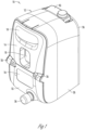
- FIG 1 shows an exemplary embodiment of a dispenser 10 for use with the present invention.
- the dispenser 10 is configured to hold a solid product chemistry that is combined with a liquid, such as water, to create a product chemistry solution.
- a liquid such as water
- the solid product chemistry may be mixed with the liquid to create a cleaning detergent solution.
- the dispenser 10 works by having the liquid and gas interact with the solid product to form a product chemistry having a desired concentration for its end use application.
- the liquid may be introduced to a bottom or other surface of the solid product, as will be disclosed.
- the dispenser 10 of the invention includes a turbulence or flow scheme control that is adjustable either manually or in real time (i.e., automatically) based on a characteristic of either the solid product or another uncontrolled condition, such as an environmental condition.
- the characteristic may be the density of the solid product, the temperature or pressure of the liquid, the climate (humidity, temperature, pressure, etc.) of the room in which the dispenser or solid product is placed, the type of liquid/fluid used, the number of solid products used, or some combination thereof.
- the dispenser 10 can be adjusted, such as adjusting a characteristic of the existing flow scheme or turbulence. The adjustments may be made based upon the use of known relationships between the characteristic and the erosion rate of the solid product, as well as the relationship between different types of turbulence and the erosion rate of the solid product.
- the turbulence or flow characteristics/scheme can be adjusted based upon known relationships between the characteristic(s) and the dispense rate of the solid chemistry. For example, by understanding the rate change of product dispense per change in degree of liquid temperature change, the turbulence can be adjusted to counteract a temperature change. The concentration is adjusted according to known relationships between the erosion or dispense rate and either the characteristic or the turbulence.
- the dispenser 10 of Figure 1 includes housing 12 comprising a front door 14 having a handle 16 thereon.
- the door 14 is mounted to the housing in any convenient manner.
- the front door 14 may be hingeably connected to a front fascia 22 via hinges 20 there between. This allows the front door 14 to be rotated about the hinge 20 to allow access into the housing 12 of the dispenser 10.
- the front door 14 also includes a window 18 therein to allow an operator to view the solid product housed within the housing 12. Once the housed product has been viewed to erode to a certain extent, the front door 14 can be opened via the handle to allow an operator to replace the solid product with a new un-eroded product.
- the front fascia 22 may include a product ID window 24 for placing a product ID label thereon.
- the product ID window 24 allows an operator to quickly determine the type of product housed within the housing 12 such that replacement thereof is quick and efficient.
- the ID label may also include other information, such as health risks, manufacturing information, date of last replacement, or the like.
- the dispenser may be activated in various ways, such as a push button, a switch, or a touch sensitive pad.
- a push button 26 is mounted to the front fascia 22 for activating the dispenser 10.
- the button 26 may be a spring-loaded button such that pressing or depressing of the button activates the dispenser 10 to discharge an amount of product chemistry solution created by the solid product and the liquid.
- the button 26 may be preprogrammed to dispense a desired amount per pressing of the button, or may continue to discharge an amount of product chemistry while the button is depressed.
- a mounting plate 30 is positioned at the rear of the dispenser 10 and includes means for mounting the dispenser to a wall or other structure.
- the dispenser 10 may be attached to a wall via screws, hooks, or other hanging means attached to the mounting plate 30.
- the components of the housing 12 of the dispenser 10 may be molded plastic or other materials, and the window 18 may be a transparent plastic such as clarified polypropylene or the like.
- the handle 16 can be connected and disconnected from the front door 14.
- a backflow prevention device 62 may be positioned at or within the rear enclosure 28 to prevent backflow of the product chemistry.
- a solid product is placed within a cavity 38, which is surrounded by walls 40.
- the solid product chemistry is placed on a support member 50.
- the support member 50 may be a grate, a screen, or otherwise include perforations to allow liquid to pass there through
- a liquid such as water
- the dispenser 10 is connected to the dispenser 10 via the liquid inlet 32 on the bottom side of the dispenser 10.
- Activating the dispenser, such as by pressing the button 26, will pass liquid into the dispenser 10 to come in contact with the product chemistry.
- the liquid is passed through a liquid source 34 via a fitment splitter 36.
- the liquid source is a split, two channel liquid source for different flow paths. Each of the paths contains a flow control (not shown) to properly distribute liquid in the intended amounts.
- This flow control can be changed to alter the turbulence of the liquid coming in contact with the solid product to adjust the turbulence based on the characteristics to maintain the formed product chemistry within an acceptable range of concentration.
- the liquid may pass through the liquid source 34 and out of the liquid source nozzle 44.
- the liquid source nozzle 44 is positioned adjacent a manifold diffuse member, which may also be known as a puck member, such that the liquid passing through the liquid nozzle 44 will be passed through manifold diffuse ports of the manifold diffuse member.
- the invention contemplates that, while positioned on the support member 50, the product chemistry may be fully submerged, partially submerged, or not submerged at all.
- the submersion level, or lack thereof can be dependent upon many factors, including, but not limited to, the chemistry of the product, the desired concentration, the fluid used to erode the chemistry, frequency of use of the dispenser, along with other factors. For example, for normal use with water as the eroding element, it has been shown that it is preferred to have the bottom portion of the product chemistry submerged to aid in controlling the erosion rate of the chemistry.
- the amount of submersion may depend on the chemistry of the block.
- submersion may be about 0.635 - 1.905 cm (0.25 - 0.75) inch, while a different block chemistry may have about 1.27 - 2.54 cm (0.5 to 1.0-inch) submersion. This will provide for a more even erosion of the product as it is used, so that there will be less of a chance of an odd amount of product left that must be discarded or otherwise wasted.
- the liquid will continue in a generally upwards orientation to come in contact with a portion or portions of the solid product supported by the product grate 50.
- the mixing of the liquid and the solid product will erode the solid product, which will dissolve portions of the solid product in the liquid to form a product chemistry.
- This product chemistry will be collected in the product chemistry collector 56, which is generally a cup-shaped member having upstanding walls and bottom floor comprising the manifold diffuse member.
- the product chemistry will continue to rise in the product chemistry collector 56 until it reaches the level of an overflow port, which is determined by the height of the wall comprising the product chemistry collector 56.
- a puck or pressurized water vessel sprays water generally upward onto the solid chemistry block. After spraying occurs, the solution cascades over the edges of this component and is collected via a funnel-shaped component for delivery out of the dispenser and into a customer's container.
- the liquid source 34 includes a second path, which ends with the diluent nozzle. Therefore, more liquid may be added to the product chemistry in the collection zone, to further dilute the product chemistry to obtain a product chemistry having a concentration within the acceptable range.
- a splash guard positioned generally around the top of the collection zone.
- the splash guard prevents product chemistry in the collection zone from spilling outside the collection zone.
- the dispenser 10 incorporates a pressurized air into the system to partially displace water used to dissolve the solid chemical block and produce a higher concentration level in the solution.
- air or other gas such as nitrogen if inert gas is needed, allows the system to maintain pressure, which is critical for impingement.
- the air also maintains the spray area for the solid block, while reducing the amount of water volume required to create a solution.
- the gas or air is also vented out of the system, and thus does not become part of the final chemistry solution.
- the use of air also eliminates, or at least minimizes, fowling or plugging of the manifold of holes.
- the use of air and water helps solve the limitations on solution concentration adjustability, without imposing drastic structural figuration changes in the dispenser 10.
- the present invention introduces air into the water line to displace liquid volume. Air aids in helping the system maintain spray pressure/volume, with the air leaving the system as soon as it erosion work is complete.
- the ratio of liquid to gas varies on a product-by-product basis, depending on the hardness of the solid product or block. Generally, a softer block requires less air than a harder block to obtain the same percentage concentration. Similarly, air pressure also varies, depending on system materials, block hardness, and water parameters.
- the block hardness can be determined based upon density, moisture content, erodibility, or other test used in industry and which may be known and/or used. Less than 68.9 kPa (10 psi) may be sufficient in some instances. However, it is considered that 0.689 to 689.5 kPa (0.1 to 100 psi) be included as part of the present disclosure for possible pressure ranges.
- the dispenser 10 is wired for electrical power inside the housing 12.
- the dispenser 10 includes an electrical air or gas pump 110.
- the air pump 110 includes a nipple 112 to which an airline (not shown for clarity) is attached.
- the airline can be single line, or split into multiple lines, for connection to plumbing points or couplers 114, so as to introduce air into the cavity 38.
- liquid, such as water, from the liquid source 34 is combined with gas, such as air, from the pump 110 to effectively dissolve solid chemistry block, and produce the concentrate solution.
- liquid such as water
- gas such as air
- the pump maybe be activated simultaneously upon pressing the button 26, or alternatively, a delay circuit for the pump 50 can be utilized to ensure the water path is established before introducing air into the system.
- the solution concentrate can be 2-3 times greater than a turbulent flow dispenser using water alone. Also, the volume of water can be reduced at least 25% due to the addition of air, thus providing costs saving to the operator.
- a pump controller with feedback sensors can provide adjustment to the amount of gas provided. This can allow for the adjustability of the pressure of the gas, the flow rate of the gas, the consistency (pulsing, constant stream, variable flow, random flow, combination, etc.) of the gas stream being input, as well as the on/off of the gas.
- the pump will provide a near real-time adjustment and operation setting of the gas towards the solid product to aid in controlling the amount of product being eroded with the combination of liquid and gas, and thereby provide a solution concentration within acceptable parameters.
- the adjustment allows for the control of concentration outputted by the system, and also gives control based upon environment changes (both ambient and based upon dispenser output), erosion rates, and/or other factors that can affect the erosion of the solid product, concentration level of the solution, or other input that may not be controllable in and around the dispensing unit.
- the following table shows test results comparing a dispenser according to the present invention run with the auxiliary air both off and on. As shown in the table, the net result is an average of approximately 2x concentration improvement with the use of gas verses no gas.
- the air pressure being used can correlate or correspond with a water pressure or temperature, such as increasing or decreasing to account for a predetermined threshold of temperature or pressure, or could be independent such that it is included based upon a concentration desired or tested.
- the dispenser 10 may also include components such as an intelligent control and communication components.
- intelligent control units may be tablets, telephones, handheld devices, laptops, user displays, or generally any other computing device capable of allowing input, providing options, and showing output of electronic functions.
- controller also can include other components and can be implemented partially or entirely on a semiconductor (e.g., a field-programmable gate array (“FPGA”)) chip, such as a chip developed through a register transfer level (“RTL”) design process.
- FPGA field-programmable gate array
- RTL register transfer level
- the memory includes, in some embodiments, a program storage area and a data storage area.
- the program storage area and the data storage area can include combinations of different types of memory, such as read-only memory ("ROM”, an example of non-volatile memory, meaning it does not lose data when it is not connected to a power source), random access memory (“RAM”, an example of volatile memory, meaning it will lose its data when not connected to a power source)
- ROM read-only memory
- RAM random access memory
- volatile memory include static RAM (“SRAM”), dynamic RAM (“DRAM”), synchronous DRAM (“SDRAM”), etc.
- SRAM static RAM
- DRAM dynamic RAM
- SDRAM synchronous DRAM
- Examples of non-volatile memory include electrically erasable programmable read only memory (“EEPROM”), flash memory, a hard disk, an SD card, etc.
- the processing unit such as a processor, a microprocessor, or a microcontroller, is connected to the memory and executes software instructions that are capable of being stored in a RAM of the memory (e.g., during execution), a ROM of the memory (e.g., on a generally permanent basis), or another non-transitory computer readable medium such as another memory or a disc.
- a RAM of the memory e.g., during execution
- ROM of the memory e.g., on a generally permanent basis
- another non-transitory computer readable medium such as another memory or a disc.
- a communications module can be included with the dispenser and can be configured to connect to and communicate with another controller, such as a computer, tablet, server, or other computing device.
- another controller such as a computer, tablet, server, or other computing device.
- This could allow the dispenser to provide data or other information (e.g., warnings, status, notices, etc.) associated with the dispenser to a remote location of the additional controller to allow the real-time information and stored information for the dispenser.
- the information could be used to determine issues, forecast, or otherwise track information related to the dispenser.
- the communication could also be in the form of inputs such that the communication could include a command to the dispenser from a remote location.
- the dispenser includes a first communications module for communicating with a secondary device (other dispenser or remote controller), and/or a second communications module for communicating with a central location (server, computer, or other master controller).
- a first communications module for communicating with a secondary device (other dispenser or remote controller), and/or a second communications module for communicating with a central location (server, computer, or other master controller).
- a central location server, computer, or other master controller.
- the term "communications module” herein applies to one or more communications modules individually or collectively operable to communicate with both the mobile reader and the central location.
- the communications module communicates with the central location through the network.
- the network is, by way of example only, a wide area network (“WAN”) (e.g., a global positioning system (“GPS”), a TCP/IP based network, a cellular network, such as, for example, a Global System for Mobile Communications (“GSM”) network, a General Packet Radio Service (“GPRS”) network, a Code Division Multiple Access (“CDMA”) network, an Evolution-Data Optimized (“EV-DO”) network, an Enhanced Data Rates for GSM Evolution (“EDGE”) network, a 3GSM network, a 4GSM network, a Digital Enhanced Cordless Telecommunications (“DECT”) network, a Digital AMPS (“IS-136/TDMA”) network, or an Integrated Digital Enhanced Network (“iDEN”) network, etc.), although other network types are possible and contemplated herein.
- the network is a GSM or other WAM which is operable to allow communication between the communications module and the central location during moments of low-
- the network is, by way of example only, a wide area network ("WAN”) such as a TCP/IP based network or a cellular network, a local area network (“LAN”), a neighborhood area network (“NAN”), a home area network (“HAN”), or a personal area network (“PAN”) employing any of a variety of communications protocols, such as Wi-Fi, Bluetooth, ZigBee, near field communication (“NFC”), etc., although other types of networks are possible and are contemplated herein.
- the network typically allows communication between the communications module and the central location during moments of low-quality connections.
- Communications through the network can be protected using one or more encryption techniques, such as those techniques provided in the IEEE 802.1 standard for port-based network security, pre-shared key, Extensible Authentication Protocol (“EAP”), Wired Equivalent Privacy (“WEP”), Temporal Key Integrity Protocol (“TKIP”), Wi-Fi Protected Access (“WPA”), and the like.
- EAP Extensible Authentication Protocol
- WEP Wired Equivalent Privacy
- TKIP Temporal Key Integrity Protocol
- WPA Wi-Fi Protected Access
- connections between the communications module and the network are wireless to enable freedom of movement and operation of the mobile cleaning machine without being physically tethered to a computer or other external processing device to facilitate such communications.
- the connections between the communications module and the network can instead be a wired connection (e.g., a docking station for the communications module, a communications cable releasably connecting the communications module and a computer or other external processing device, or other communications interface hardware), or a combination of wireless and wired connections.
- the connections between the controller and the network or the network communications module are wired connections, wireless connections, or a combination of wireless and wired connections in any of the forms just described.
- the controller or communications module includes one or more communications ports (e.g., Ethernet, serial advanced technology attachment (“SATA”), universal serial bus (“USB”), integrated drive electronics (“IDE”), etc.) for transferring, receiving, or storing data.
- SATA serial advanced technology attachment
- USB universal serial bus
- IDE integrated drive electronics
- the central location can include a centrally located computer, a network of computers, or one or more centrally located servers.
- the central location can be adapted to store, interpret, and communicate data from one or more dispensers 10, and can also interpret the data and communicate the interpreted data to a user.
Landscapes
- Chemical & Material Sciences (AREA)
- Chemical Kinetics & Catalysis (AREA)
- General Chemical & Material Sciences (AREA)
- Feeding, Discharge, Calcimining, Fusing, And Gas-Generation Devices (AREA)
- Accessories For Mixers (AREA)
Claims (11)
- Spender (10) zum Abgeben einer Lösung, die aus einem festen Produkt hergestellt ist, umfassend:ein Gehäuse (12), das einen Hohlraum (38) aufweist, um das feste Produkt aufzunehmen;eine Fluidquelle (34), die Flüssigkeit und Gas angrenzend an den festen Block kombiniert, um mit dem festen Produkt in Kontakt zu kommen und dadurch das feste Produkt zu erodieren, um die Lösungen aus dem erodierten festen Produkt und der Flüssigkeit herzustellen;einen Einrichtungsteiler (36), der mindestens zwei separate Strömungswege erzeugt, wobei jeder der Strömungswege eine Strömungssteuerung einschließt, die Turbulenzen in der Flüssigkeit verursacht, die sich zwischen dem festen Produkt und der Fluidquelle (34) befindet; undeinen Auslass in dem Gehäuse (12) zum Abgeben der Lösung;ferner umfassend eine Luftpumpe (110) innerhalb des Gehäuses (12) zum Versorgen des Hohlraums (38) mit Luft und eine Pumpensteuerung mit Rückkopplungssensoren, um eine Anpassung der Menge des bereitgestellten Gases bereitzustellen.
- Spender (10) nach Anspruch 1, ferner umfassend eine Vielzahl von Öffnungen angrenzend an den Hohlraum (38), wobei die Fluidquelle (34) stromaufwärts von den Öffnungen ist.
- Spender (10) nach Anspruch 1 oder 2, ferner umfassend mindestens eine Öffnung zum Einführen der Flüssigkeit und des Gases.
- Spender (10) nach einem der vorstehenden Ansprüche, ferner umfassend separate Flüssigkeits- und Gasleitungen, die mit dem Hohlraum (38) verbunden sind, um die Flüssigkeit und das Gas dem Hohlraum (38) zuzuführen.
- Spender (10) nach einem der vorstehenden Ansprüche, ferner umfassend ein Verteiler-Diffusorelement, das Verteiler-Diffusoröffnungen aufweist, und angrenzend an eine Fluidquellendüse der Fluidquelle (34) positioniert ist.
- Spender (10) nach Anspruch 5, ferner umfassend einen Produktchemiesammler (56) einschließlich aufrecht stehender Wände und eines unteren Bodens, umfassend das Verteiler-Diffusionselement.
- Verfahren, umfassend:Abgeben einer Lösung, die mit dem Spender (10) nach einem der vorstehenden Ansprüche hergestellt ist;ferner umfassend das Anpassen der bereitgestellten Gasmenge.
- Verfahren nach Anspruch 7, ferner umfassend das Anpassen der Eigenschaften der Flüssigkeit und/oder des Gases vor dem Einführen durch mindestens eine Öffnung.
- Verfahren nach Anspruch 7 oder 8, wobei die Eigenschaften in Echtzeit basierend auf einer Dichte des festen Produkts, einer Umgebungs- oder Klimabedingung, einem Typ der verwendeten Flüssigkeit, einer Anzahl der verwendeten festen Produkte oder einer Kombination davon angepasst werden.
- Verfahren nach einem der Ansprüche 7 bis 9, wobei die Eigenschaften Druck, Volumen, Temperatur, Geschwindigkeit, Turbulenz, Strömungsrate, Vektor und/oder Aufprall umfassen.
- Verfahren nach einem der Ansprüche 7 bis 10, ferner umfassend das Verteilen der Flüssigkeit mit der Strömungssteuerung.
Priority Applications (1)
| Application Number | Priority Date | Filing Date | Title |
|---|---|---|---|
| HRP20241391TT HRP20241391T1 (hr) | 2017-10-27 | 2018-10-26 | Postupak za povećanje otapanja krutih kemijskih blokova |
Applications Claiming Priority (2)
| Application Number | Priority Date | Filing Date | Title |
|---|---|---|---|
| US201762578279P | 2017-10-27 | 2017-10-27 | |
| PCT/US2018/057718 WO2019084409A1 (en) | 2017-10-27 | 2018-10-26 | METHOD FOR INCREASING DISSOLUTION OF SOLID CHEMICAL BLOCKS |
Publications (3)
| Publication Number | Publication Date |
|---|---|
| EP3684498A1 EP3684498A1 (de) | 2020-07-29 |
| EP3684498B1 true EP3684498B1 (de) | 2024-08-21 |
| EP3684498C0 EP3684498C0 (de) | 2024-08-21 |
Family
ID=64277862
Family Applications (1)
| Application Number | Title | Priority Date | Filing Date |
|---|---|---|---|
| EP18801175.3A Active EP3684498B1 (de) | 2017-10-27 | 2018-10-26 | Verfahren zur erhöhung der auflösung von festen chemischen blöcken |
Country Status (13)
| Country | Link |
|---|---|
| US (2) | US10773220B2 (de) |
| EP (1) | EP3684498B1 (de) |
| JP (1) | JP7128888B2 (de) |
| CN (2) | CN111263658A (de) |
| AU (1) | AU2018354382B2 (de) |
| CA (1) | CA3080613C (de) |
| ES (1) | ES2989332T3 (de) |
| HR (1) | HRP20241391T1 (de) |
| HU (1) | HUE068402T2 (de) |
| MX (1) | MX2020004361A (de) |
| NZ (1) | NZ763505A (de) |
| PL (1) | PL3684498T3 (de) |
| WO (1) | WO2019084409A1 (de) |
Families Citing this family (1)
| Publication number | Priority date | Publication date | Assignee | Title |
|---|---|---|---|---|
| EP3684498B1 (de) * | 2017-10-27 | 2024-08-21 | Ecolab Usa Inc. | Verfahren zur erhöhung der auflösung von festen chemischen blöcken |
Citations (2)
| Publication number | Priority date | Publication date | Assignee | Title |
|---|---|---|---|---|
| WO2014130477A1 (en) * | 2013-02-20 | 2014-08-28 | Ecolab Usa Inc. | Global backflow prevention assembly |
| WO2019032985A1 (en) * | 2017-08-11 | 2019-02-14 | Ecolab Usa Inc. | SOLID CHEMICAL ENCLOSURE WITH SECURITY LOCK FOR DISTRIBUTION APPLICATIONS |
Family Cites Families (44)
| Publication number | Priority date | Publication date | Assignee | Title |
|---|---|---|---|---|
| US3638833A (en) * | 1970-02-09 | 1972-02-01 | Purex Corp Ltd | Means for chlorinating swimming pools |
| US3864090A (en) | 1973-10-12 | 1975-02-04 | Kenneth Richards | Pressure-type tablet hypochlorinating device |
| US4398669A (en) | 1977-05-09 | 1983-08-16 | Teledyne Industries, Inc. | Fluid-spray discharge apparatus |
| JPS6314957Y2 (de) * | 1984-11-06 | 1988-04-26 | ||
| US4690305A (en) | 1985-11-06 | 1987-09-01 | Ecolab Inc. | Solid block chemical dispenser for cleaning systems |
| US4790981A (en) | 1985-11-25 | 1988-12-13 | James L. Mayer | Dispenser for solid and powdered detergent |
| US5089127A (en) | 1990-10-19 | 1992-02-18 | Ppg Industries, Inc. | Chemical feed apparatus |
| US5133381A (en) | 1990-10-29 | 1992-07-28 | Olin Corporation | Dual range periodic chemical dispenser for swimming pools |
| US5505915A (en) | 1993-10-05 | 1996-04-09 | Ecolab Inc. | Solid chemical dispenser with movable nozzle |
| US5389344A (en) | 1993-10-05 | 1995-02-14 | Ecolab Inc. | Variable concentration, solid chemical dispenser |
| DE4336339C2 (de) | 1993-10-25 | 1998-07-02 | Woellner Werke | Verpackungs- und Dosiersystem für pulver- und granulatförmige Detergentien und sonstige Wasserbehandlungs- und/oder Prozeßchemikalien und Verfahren zum Einspülen und Dosieren unter Verwendung des Systems |
| US5441073A (en) | 1994-03-07 | 1995-08-15 | Hoadley; Francis B. | Apparatus for controlled release of an erodible solid into a liquid |
| US5427748A (en) | 1994-04-21 | 1995-06-27 | Ppg Industries, Inc. | Chemical feeder |
| US5911242A (en) | 1994-09-16 | 1999-06-15 | Ranco Incorporated Of Delaware | Reversing valve and method |
| US5637230A (en) * | 1994-10-12 | 1997-06-10 | City Of Chandler | Water treatment method and apparatus for adding calcium hypochlorite to potable water |
| US5494644A (en) | 1994-12-06 | 1996-02-27 | Ecolab Inc. | Multiple product dispensing system including dispenser for forming use solution from solid chemical compositions |
| US5810043A (en) | 1997-04-14 | 1998-09-22 | Magi-Eau Inc. | Automatic chlorinator |
| US5897770A (en) | 1997-10-23 | 1999-04-27 | Plymouth Products, Inc. | Center core cartridge feeder insert |
| US5928608A (en) | 1998-01-08 | 1999-07-27 | Arch Chemicals Inc. | Intermittant spray system for water treatment |
| US6423280B1 (en) | 1998-10-29 | 2002-07-23 | Ecolab Inc. | Hydraulic control of detergent concentration in an automatic warewashing machine |
| SE515651C2 (sv) | 1999-01-14 | 2001-09-17 | Tour & Andersson Hydronics Ab | Termisk reglerventil |
| US6337024B1 (en) * | 1999-07-13 | 2002-01-08 | Hammonds Technical Services, Inc. | Chlorination apparatus and method |
| US6517727B2 (en) * | 2001-06-26 | 2003-02-11 | Ppg Industries Ohio, Inc. | Method of operating a chemical feeder |
| US7530466B2 (en) | 2002-01-08 | 2009-05-12 | Omnitek Partners Llc | Temperature sensitive valve having shape memory actuator |
| US7300196B2 (en) | 2004-03-10 | 2007-11-27 | John Fleig | Automatic dilution system with overflow protection |
| US20050244315A1 (en) | 2004-04-30 | 2005-11-03 | Greaves Michael D | Solid product dissolver and method of use thereof |
| US7325747B2 (en) | 2004-05-18 | 2008-02-05 | Masco Corporation Of Indiana | Flow compensated control valve |
| US7708023B2 (en) | 2004-10-18 | 2010-05-04 | Ecolab Inc. | Solid product dispenser |
| US7597861B2 (en) | 2004-10-18 | 2009-10-06 | Ecolab Inc. | Method and apparatus to control dispensing rate of a solid product with changing temperature |
| GB0500970D0 (en) | 2005-01-18 | 2005-02-23 | Kohler Mira Ltd | Improvements in or relating to ablutionary Installations |
| US20060231683A1 (en) | 2005-04-18 | 2006-10-19 | Orr James R | Aircraft & motor vehicle protection system that eliminates eleven safety and environmental hazards associated with aircraft and vehicles parked or tied down and exposed to the elements and animals |
| US7913926B2 (en) | 2006-02-17 | 2011-03-29 | Watts Water Technologies, Inc. | Thermostatic mixing valve |
| PL2014210T3 (pl) | 2006-04-27 | 2011-02-28 | Ecolab Inc | Obudowa produktu przeznaczona dla dozownika produktu w postaci stałej |
| US8617481B1 (en) | 2008-03-07 | 2013-12-31 | King Technology Inc. | Indexable dispenser cartridges |
| US8007664B2 (en) | 2008-09-05 | 2011-08-30 | Chemtura Corporation | Floating dispenser for dispensing a solid dissolvable chemical into ambient water |
| EP2169511B1 (de) | 2008-09-26 | 2012-08-08 | Toto Ltd. | Wasser- und Heißwassermischvorrichtung |
| JP6367519B2 (ja) * | 2010-12-15 | 2018-08-01 | 松本 高明 | 混合装置、混合流体製造装置、混合流体の製造方法とこれによって製造された混合流体、および酸素を含む水、氷 |
| US9022642B2 (en) | 2011-04-28 | 2015-05-05 | Hubert Ray Broome | Dissolution generator, method of dissolving powder, and mixing system |
| US9314747B2 (en) * | 2011-10-24 | 2016-04-19 | King Technology, Inc. | Cartridges for bulk feeders |
| CN104349845B (zh) | 2012-02-21 | 2018-06-29 | 艺康美国股份有限公司 | 受控溶解固体产品分配器 |
| CA3122678C (en) * | 2013-02-20 | 2023-09-26 | Ecolab Usa Inc. | Method and apparatus for variation of flow to erode solid chemistry |
| US10549245B2 (en) * | 2014-08-05 | 2020-02-04 | Ecolab Usa Inc. | Apparatus and method for dispensing solutions from solid products |
| US9850060B2 (en) * | 2014-08-05 | 2017-12-26 | Ecolab Usa Inc. | Multiple solid products liquid solution dispenser |
| EP3684498B1 (de) * | 2017-10-27 | 2024-08-21 | Ecolab Usa Inc. | Verfahren zur erhöhung der auflösung von festen chemischen blöcken |
-
2018
- 2018-10-26 EP EP18801175.3A patent/EP3684498B1/de active Active
- 2018-10-26 AU AU2018354382A patent/AU2018354382B2/en active Active
- 2018-10-26 PL PL18801175.3T patent/PL3684498T3/pl unknown
- 2018-10-26 ES ES18801175T patent/ES2989332T3/es active Active
- 2018-10-26 MX MX2020004361A patent/MX2020004361A/es unknown
- 2018-10-26 CN CN201880069011.1A patent/CN111263658A/zh active Pending
- 2018-10-26 HR HRP20241391TT patent/HRP20241391T1/hr unknown
- 2018-10-26 US US16/171,659 patent/US10773220B2/en active Active
- 2018-10-26 CA CA3080613A patent/CA3080613C/en active Active
- 2018-10-26 JP JP2020523444A patent/JP7128888B2/ja active Active
- 2018-10-26 CN CN202511512117.2A patent/CN121222291A/zh active Pending
- 2018-10-26 WO PCT/US2018/057718 patent/WO2019084409A1/en not_active Ceased
- 2018-10-26 HU HUE18801175A patent/HUE068402T2/hu unknown
- 2018-10-26 NZ NZ763505A patent/NZ763505A/en unknown
-
2020
- 2020-08-17 US US16/947,783 patent/US11826712B2/en active Active
Patent Citations (3)
| Publication number | Priority date | Publication date | Assignee | Title |
|---|---|---|---|---|
| WO2014130477A1 (en) * | 2013-02-20 | 2014-08-28 | Ecolab Usa Inc. | Global backflow prevention assembly |
| WO2019032985A1 (en) * | 2017-08-11 | 2019-02-14 | Ecolab Usa Inc. | SOLID CHEMICAL ENCLOSURE WITH SECURITY LOCK FOR DISTRIBUTION APPLICATIONS |
| EP3664922A1 (de) * | 2017-08-11 | 2020-06-17 | Ecolab USA Inc. | Festkörperchemiebehälter mit sicherheitsverschluss für ausgabeanwendungen |
Also Published As
| Publication number | Publication date |
|---|---|
| JP2021501045A (ja) | 2021-01-14 |
| PL3684498T3 (pl) | 2024-11-04 |
| ES2989332T3 (es) | 2024-11-26 |
| BR112020008047A2 (pt) | 2020-10-27 |
| EP3684498A1 (de) | 2020-07-29 |
| CA3080613C (en) | 2022-10-04 |
| CN111263658A (zh) | 2020-06-09 |
| US11826712B2 (en) | 2023-11-28 |
| US10773220B2 (en) | 2020-09-15 |
| CA3080613A1 (en) | 2019-05-02 |
| WO2019084409A1 (en) | 2019-05-02 |
| AU2018354382B2 (en) | 2021-05-27 |
| MX2020004361A (es) | 2020-08-03 |
| AU2018354382A1 (en) | 2020-04-30 |
| US20200376447A1 (en) | 2020-12-03 |
| HUE068402T2 (hu) | 2024-12-28 |
| NZ763505A (en) | 2021-12-24 |
| EP3684498C0 (de) | 2024-08-21 |
| HRP20241391T1 (hr) | 2024-12-20 |
| US20190126213A1 (en) | 2019-05-02 |
| JP7128888B2 (ja) | 2022-08-31 |
| CN121222291A (zh) | 2025-12-30 |
Similar Documents
| Publication | Publication Date | Title |
|---|---|---|
| ES2839875T3 (es) | Disolución controlada de un producto sólido | |
| US10549245B2 (en) | Apparatus and method for dispensing solutions from solid products | |
| US11826712B2 (en) | Method for increasing dissolution of solid chemistry blocks | |
| US10456756B2 (en) | Solid chemistry enclosure with safety lock for dispensing applications | |
| CN108000368B (zh) | 曲边玻璃盖板防眩表面处理设备与处理方法 | |
| KR101692525B1 (ko) | 슬릿 코터용 슬릿 노즐 및 이를 사용한 약액 공급 시스템 | |
| EP3781294B1 (de) | Dispensieren einer festen chemie unter verwendung eines regelbaren verteilers mit wirbelstromtechnik | |
| BR112020008047B1 (pt) | Dispensador para dispensar uma solução produzida de um produto sólido, e, método para obter uma química de produto de um produto sólido | |
| CN108023980B (zh) | 异形玻璃盖板防眩表面处理设备与处理方法 | |
| BR112020002691B1 (pt) | Cápsula para armazenar produto sólido cáustico, dispensador de fluxo turbulento para produzir uma solução de um produto sólido cáustico, e, método para obter um produto de química a partir de um produto sólido cáustico | |
| KR100846575B1 (ko) | 평판 디스플레이 글라스 세정용 이류체 분사 장치 |
Legal Events
| Date | Code | Title | Description |
|---|---|---|---|
| REG | Reference to a national code |
Ref country code: HR Ref legal event code: TUEP Ref document number: P20241391T Country of ref document: HR |
|
| STAA | Information on the status of an ep patent application or granted ep patent |
Free format text: STATUS: UNKNOWN |
|
| STAA | Information on the status of an ep patent application or granted ep patent |
Free format text: STATUS: THE INTERNATIONAL PUBLICATION HAS BEEN MADE |
|
| PUAI | Public reference made under article 153(3) epc to a published international application that has entered the european phase |
Free format text: ORIGINAL CODE: 0009012 |
|
| STAA | Information on the status of an ep patent application or granted ep patent |
Free format text: STATUS: REQUEST FOR EXAMINATION WAS MADE |
|
| 17P | Request for examination filed |
Effective date: 20200423 |
|
| AK | Designated contracting states |
Kind code of ref document: A1 Designated state(s): AL AT BE BG CH CY CZ DE DK EE ES FI FR GB GR HR HU IE IS IT LI LT LU LV MC MK MT NL NO PL PT RO RS SE SI SK SM TR |
|
| AX | Request for extension of the european patent |
Extension state: BA ME |
|
| DAV | Request for validation of the european patent (deleted) | ||
| DAX | Request for extension of the european patent (deleted) | ||
| STAA | Information on the status of an ep patent application or granted ep patent |
Free format text: STATUS: EXAMINATION IS IN PROGRESS |
|
| 17Q | First examination report despatched |
Effective date: 20220126 |
|
| REG | Reference to a national code |
Ipc: B01F0021200000 Ref country code: DE Ref legal event code: R079 Ref document number: 602018073394 Country of ref document: DE Free format text: PREVIOUS MAIN CLASS: B01F0001000000 Ipc: B01F0021200000 |
|
| GRAP | Despatch of communication of intention to grant a patent |
Free format text: ORIGINAL CODE: EPIDOSNIGR1 |
|
| STAA | Information on the status of an ep patent application or granted ep patent |
Free format text: STATUS: GRANT OF PATENT IS INTENDED |
|
| RIC1 | Information provided on ipc code assigned before grant |
Ipc: B01F 35/71 20220101ALI20240301BHEP Ipc: B01F 35/22 20220101ALI20240301BHEP Ipc: B01F 21/00 20220101ALI20240301BHEP Ipc: B01F 21/20 20220101AFI20240301BHEP |
|
| INTG | Intention to grant announced |
Effective date: 20240327 |
|
| GRAS | Grant fee paid |
Free format text: ORIGINAL CODE: EPIDOSNIGR3 |
|
| GRAA | (expected) grant |
Free format text: ORIGINAL CODE: 0009210 |
|
| STAA | Information on the status of an ep patent application or granted ep patent |
Free format text: STATUS: THE PATENT HAS BEEN GRANTED |
|
| AK | Designated contracting states |
Kind code of ref document: B1 Designated state(s): AL AT BE BG CH CY CZ DE DK EE ES FI FR GB GR HR HU IE IS IT LI LT LU LV MC MK MT NL NO PL PT RO RS SE SI SK SM TR |
|
| REG | Reference to a national code |
Ref country code: GB Ref legal event code: FG4D |
|
| REG | Reference to a national code |
Ref country code: CH Ref legal event code: EP |
|
| REG | Reference to a national code |
Ref country code: DE Ref legal event code: R096 Ref document number: 602018073394 Country of ref document: DE |
|
| REG | Reference to a national code |
Ref country code: IE Ref legal event code: FG4D |
|
| U01 | Request for unitary effect filed |
Effective date: 20240918 |
|
| U07 | Unitary effect registered |
Designated state(s): AT BE BG DE DK EE FI FR IT LT LU LV MT NL PT RO SE SI Effective date: 20241008 |
|
| U20 | Renewal fee for the european patent with unitary effect paid |
Year of fee payment: 7 Effective date: 20241007 |
|
| REG | Reference to a national code |
Ref country code: ES Ref legal event code: FG2A Ref document number: 2989332 Country of ref document: ES Kind code of ref document: T3 Effective date: 20241126 |
|
| REG | Reference to a national code |
Ref country code: HR Ref legal event code: T1PR Ref document number: P20241391 Country of ref document: HR |
|
| REG | Reference to a national code |
Ref country code: HU Ref legal event code: AG4A Ref document number: E068402 Country of ref document: HU |
|
| PG25 | Lapsed in a contracting state [announced via postgrant information from national office to epo] |
Ref country code: GR Free format text: LAPSE BECAUSE OF FAILURE TO SUBMIT A TRANSLATION OF THE DESCRIPTION OR TO PAY THE FEE WITHIN THE PRESCRIBED TIME-LIMIT Effective date: 20241122 |
|
| PG25 | Lapsed in a contracting state [announced via postgrant information from national office to epo] |
Ref country code: IS Free format text: LAPSE BECAUSE OF FAILURE TO SUBMIT A TRANSLATION OF THE DESCRIPTION OR TO PAY THE FEE WITHIN THE PRESCRIBED TIME-LIMIT Effective date: 20241221 |
|
| PG25 | Lapsed in a contracting state [announced via postgrant information from national office to epo] |
Ref country code: RS Free format text: LAPSE BECAUSE OF FAILURE TO SUBMIT A TRANSLATION OF THE DESCRIPTION OR TO PAY THE FEE WITHIN THE PRESCRIBED TIME-LIMIT Effective date: 20241121 |
|
| PG25 | Lapsed in a contracting state [announced via postgrant information from national office to epo] |
Ref country code: RS Free format text: LAPSE BECAUSE OF FAILURE TO SUBMIT A TRANSLATION OF THE DESCRIPTION OR TO PAY THE FEE WITHIN THE PRESCRIBED TIME-LIMIT Effective date: 20241121 Ref country code: IS Free format text: LAPSE BECAUSE OF FAILURE TO SUBMIT A TRANSLATION OF THE DESCRIPTION OR TO PAY THE FEE WITHIN THE PRESCRIBED TIME-LIMIT Effective date: 20241221 Ref country code: GR Free format text: LAPSE BECAUSE OF FAILURE TO SUBMIT A TRANSLATION OF THE DESCRIPTION OR TO PAY THE FEE WITHIN THE PRESCRIBED TIME-LIMIT Effective date: 20241122 |
|
| REG | Reference to a national code |
Ref country code: HR Ref legal event code: ODRP Ref document number: P20241391 Country of ref document: HR Payment date: 20250109 Year of fee payment: 7 |
|
| PG25 | Lapsed in a contracting state [announced via postgrant information from national office to epo] |
Ref country code: SM Free format text: LAPSE BECAUSE OF FAILURE TO SUBMIT A TRANSLATION OF THE DESCRIPTION OR TO PAY THE FEE WITHIN THE PRESCRIBED TIME-LIMIT Effective date: 20240821 |
|
| PG25 | Lapsed in a contracting state [announced via postgrant information from national office to epo] |
Ref country code: CZ Free format text: LAPSE BECAUSE OF FAILURE TO SUBMIT A TRANSLATION OF THE DESCRIPTION OR TO PAY THE FEE WITHIN THE PRESCRIBED TIME-LIMIT Effective date: 20240821 |
|
| PG25 | Lapsed in a contracting state [announced via postgrant information from national office to epo] |
Ref country code: SK Free format text: LAPSE BECAUSE OF FAILURE TO SUBMIT A TRANSLATION OF THE DESCRIPTION OR TO PAY THE FEE WITHIN THE PRESCRIBED TIME-LIMIT Effective date: 20240821 |
|
| PLBE | No opposition filed within time limit |
Free format text: ORIGINAL CODE: 0009261 |
|
| STAA | Information on the status of an ep patent application or granted ep patent |
Free format text: STATUS: NO OPPOSITION FILED WITHIN TIME LIMIT |
|
| PG25 | Lapsed in a contracting state [announced via postgrant information from national office to epo] |
Ref country code: MC Free format text: LAPSE BECAUSE OF FAILURE TO SUBMIT A TRANSLATION OF THE DESCRIPTION OR TO PAY THE FEE WITHIN THE PRESCRIBED TIME-LIMIT Effective date: 20240821 |
|
| 26N | No opposition filed |
Effective date: 20250522 |
|
| PGFP | Annual fee paid to national office [announced via postgrant information from national office to epo] |
Ref country code: PL Payment date: 20250815 Year of fee payment: 8 |
|
| U20 | Renewal fee for the european patent with unitary effect paid |
Year of fee payment: 8 Effective date: 20250909 |
|
| PGFP | Annual fee paid to national office [announced via postgrant information from national office to epo] |
Ref country code: GB Payment date: 20250904 Year of fee payment: 8 |
|
| PGFP | Annual fee paid to national office [announced via postgrant information from national office to epo] |
Ref country code: HR Payment date: 20250901 Year of fee payment: 8 |
|
| PGFP | Annual fee paid to national office [announced via postgrant information from national office to epo] |
Ref country code: IE Payment date: 20250812 Year of fee payment: 8 |
|
| REG | Reference to a national code |
Ref country code: CH Ref legal event code: U11 Free format text: ST27 STATUS EVENT CODE: U-0-0-U10-U11 (AS PROVIDED BY THE NATIONAL OFFICE) Effective date: 20251101 |
|
| REG | Reference to a national code |
Ref country code: HR Ref legal event code: ODRP Ref document number: P20241391 Country of ref document: HR Payment date: 20250901 Year of fee payment: 8 |
|
| PGFP | Annual fee paid to national office [announced via postgrant information from national office to epo] |
Ref country code: HU Payment date: 20250929 Year of fee payment: 8 |
|
| PGFP | Annual fee paid to national office [announced via postgrant information from national office to epo] |
Ref country code: NO Payment date: 20251009 Year of fee payment: 8 |
|
| PGFP | Annual fee paid to national office [announced via postgrant information from national office to epo] |
Ref country code: CH Payment date: 20251101 Year of fee payment: 8 |
|
| PG25 | Lapsed in a contracting state [announced via postgrant information from national office to epo] |
Ref country code: CY Free format text: LAPSE BECAUSE OF FAILURE TO SUBMIT A TRANSLATION OF THE DESCRIPTION OR TO PAY THE FEE WITHIN THE PRESCRIBED TIME-LIMIT; INVALID AB INITIO Effective date: 20181026 |
|
| PGFP | Annual fee paid to national office [announced via postgrant information from national office to epo] |
Ref country code: ES Payment date: 20251107 Year of fee payment: 8 |