EP3684458B1 - Retina-implantat - Google Patents
Retina-implantat Download PDFInfo
- Publication number
- EP3684458B1 EP3684458B1 EP18765132.8A EP18765132A EP3684458B1 EP 3684458 B1 EP3684458 B1 EP 3684458B1 EP 18765132 A EP18765132 A EP 18765132A EP 3684458 B1 EP3684458 B1 EP 3684458B1
- Authority
- EP
- European Patent Office
- Prior art keywords
- electrodes
- electrode
- carrier
- carrier surface
- implant according
- Prior art date
- Legal status (The legal status is an assumption and is not a legal conclusion. Google has not performed a legal analysis and makes no representation as to the accuracy of the status listed.)
- Active
Links
Images



Classifications
-
- A—HUMAN NECESSITIES
- A61—MEDICAL OR VETERINARY SCIENCE; HYGIENE
- A61N—ELECTROTHERAPY; MAGNETOTHERAPY; RADIATION THERAPY; ULTRASOUND THERAPY
- A61N1/00—Electrotherapy; Circuits therefor
- A61N1/02—Details
- A61N1/04—Electrodes
- A61N1/05—Electrodes for implantation or insertion into the body, e.g. heart electrode
- A61N1/0526—Head electrodes
- A61N1/0543—Retinal electrodes
-
- A—HUMAN NECESSITIES
- A61—MEDICAL OR VETERINARY SCIENCE; HYGIENE
- A61N—ELECTROTHERAPY; MAGNETOTHERAPY; RADIATION THERAPY; ULTRASOUND THERAPY
- A61N1/00—Electrotherapy; Circuits therefor
- A61N1/18—Applying electric currents by contact electrodes
- A61N1/32—Applying electric currents by contact electrodes alternating or intermittent currents
- A61N1/36—Applying electric currents by contact electrodes alternating or intermittent currents for stimulation
- A61N1/36046—Applying electric currents by contact electrodes alternating or intermittent currents for stimulation of the eye
Definitions
- the invention relates to a retina implant having an electrode carrier to which a plurality of electrodes are connected, and an electronic controller connected to the electrode carrier for providing stimulation signals to the electrodes.
- Retina implants of this type also referred to as visual prostheses, include a plurality of electrodes which are implanted within an eye of a patient, so that electrical stimulation signals applied to the electrodes activate nearby retinal nervous cells, in particular ganglion cells. Electrical stimulation of retinal ganglion cells was shown to create visual sensations named phosphenes. Apparently, this approach is suitable for patients suffering from various diseases affecting in particular photoreceptor mechanisms of the retina, while leaving the ganglionic cells intact, such as retinitis pigmentosa or other inherited retina degenerations.
- the electronic controller of a retina implant is combined with a camera or other technical means for converting incoming light into electrical signals.
- These technical means may include a CCD or other photodetectors.
- External cameras may be used, as well as photodetectors attached to or integrated within an electrode carrier implanted into the eye.
- the document US 2004/0082981 A1 shows an example of a micro photodetector retina implant having a two-dimensional carrier surface carrying a plurality of electrodes arranged in a rectangular grid.
- the photodetectors are integrated with the carrier surface, surrounding the electrodes.
- the document US 2008/0228242 A1 describes another retina implant having an electrode array implanted within an eye and connected to an electronic controller.
- the electronic controller is connected to an external camera including an image processor via a wireless interface.
- the document EP 1 762 269 A2 discloses a retinal implant whose electrodes are designed so that they conform to the retinal curvature.
- the retina implant comprises
- the electrode carrier may have a generally plate-like shape. It may comprise a rigid and/or stiff material, such as a semiconducor substrate, or a flexible material such as a polymeric film.
- the thickness of the electrode carrier may be small compared to its lateral dimensions.
- the overall shape of the electrode carrier may be circular or rectangular, for example.
- the two-dimensional carrier surface may be flat or curved in one or two dimensions.
- the electrode carrier including the plurality of electrodes attached to the carrier surface is implanted within a patient's eye such that the carrier surface faces a layer of a retina.
- This layer in particular is a ganglionic layer of the retina.
- the electronic controller is connected to the electrodes for providing stimulation signals to the electrodes.
- the electronic controller may be attached to or formed integral with the electrode carrier. In this case, the electronic controller will be implanted at the retina.
- the electronic controller may be connected to the electrode carrier via one or more cables. In this case, the electronic controller may still be implanted within a patient's eye, for example at the retina and in a certain distance from the electrode carrier, or at any other location within or external to the eye.
- the electrode controller can be adapted to control the characteristics of the stimulation signals, in particular a shape of a stimulating pulse, an amplitude of the electrical current of a stimulating pulse, and/or a selection of a first set of electrodes functioning as active electrodes and/or a selection of a second set of electrodes functioning as ground electrodes. This gives flexibility in defining effective and safe stimulation signals under different conditions.
- the electronic controller is adapted to provide stimulation signals to the electrodes.
- the electronic controller is adapted to address each one of the electrodes, one or more at a time, as well as in a consecutive manner.
- the stimulation signals will be controlled by the electronic controller in order to create phosphenes, in particular in accordance with a pattern of light incident onto a receiver interfaced with the electronic controller.
- the light receiver may include for example a camera with a CCD or any other type of photodetectors.
- the light receiver may form a part of the retina implant implanted within the eye as well or it may be placed externally and connected to the electronic controller wirelessly, for example.
- the electrodes are arranged in varying distances from the carrier surface. This means that the electrodes are positioned at least in part outside of the electrode carrier so that when implanted, they will be positioned within the layer of the retina at which the carrier surface is implanted. Arranged in varying distances from the carrier surface means the plurality of electrodes are distributed over a certain volume which may extend from the carrier surface into the retinal layer.
- the inventive three-dimensional arrangement of the electrodes it is possible to narrow the activation area so that a smaller number of ganglionic cells or even a single ganglionic cell can be activated selectively. Without wishing to be bound by theory, it is believed that this in part is due to the fact that potential differences and corresponding current paths between different electrodes can be limited to smaller volumes within the retinal tissue. In particular, one may find suitable combinations of electrodes being positioned at different sides of a certain ganglionic cell, so that the delivering electrical current between these electrodes runs more or less directly through the respective ganglionic cell.
- Another advantage of the three-dimensional arrangement of the electrodes is that by selecting suitable electrodes one may compensate for positioning tolerances occurring when implanting the electrode carrier.
- At least one of the electrodes is positioned in a minimum distance from the carrier surface, the minimum distance in particular being less than 10 ⁇ m.
- the minimum distance from the carrier surface may be zero or almost zero when the electrodes closest to the carrier surface are placed directly at the carrier surface.
- At least one of the electrodes is positioned in a maximum distance from the carrier surface, the maximum distance being more than 50 ⁇ m. This allows to cover a substantial part of the respective retinal layer by the volume arranged between the closest and most distal electrodes.
- the electrodes placed in the maximum distance from the carrier surface will penetrate sufficiently deeply into the retinal layer if the electrode carrier is implanted in the intended manner.
- the carrier surface comprises a plurality of electrode connecting points arranged in a pattern on the carrier surface, each of the electrode connecting points being connected to at least one of the electrodes.
- each of the electrode connecting points will be connected to more than one of the electrodes, for example to a number of electrodes ranging from 3 to 50.
- the electrode connecting point may include a corresponding number of contacts.
- the pattern in which the electrode connecting points are arranged on the carrier surface may be a regular pattern, in particular a rectangular grid of electrode connecting points.
- a plurality of linear carrier elements each of the linear carrier elements being connected to an electrode connecting point and carrying a plurality of the electrodes.
- the electrodes carried by a linear carrier element may be arranged along a substantially straight line, or along a curved trajectory.
- the linear carrier elements can facilitate the desired placement of the electrodes within the respective retinal layer.
- the linear carrier elements may penetrate into or through this layer.
- the linear carrier element may be made from a flexible material such as a polymeric film. It may be made from a semiconducting material, in particular silicon.
- the linear carrier element may be made of an electrically conducting or electrically isolating material.
- the dimensions and mechanical properties of the linear carrier element may be selected such that it can be placed within the retinal tissue without causing substantial damage of the nervous cells.
- the linear carrier element may include one or more conductive paths, such as electrically conductive filaments or other electrical conductors.
- the conductive paths may be electrically isolated from each other and/or from the surrounding environment. Each of the conductive paths may be electrically connected to a single one of the electrodes.
- the linear carrier elements each comprise a wire, wherein the plurality of the electrodes carried by the respective linear carrier element are affixed to the wire.
- the wire serves to provide sufficient mechanical stability to the linear carrier element, so that the same can be placed within the respective retinal tissue in a desired position.
- each linear carrier element comprises a plurality of decoding circuits, each of the decoding circuits being assigned to one of the electrodes of the corresponding linear carrier element, and a fixed number of conductive paths which are all connected to each of the decoding circuits.
- Each of the decoding circuits may be arranged close to an electrode.
- Each electrode of a linear carrier element can be addressed via the same fixed number of conductive paths.
- each of the electrodes may comprise a decoding circuit adapted to connect the corresponding electrode to a current source or to ground under the control of a logic signal sent via one or more of the conductive paths from the electronic controller and decoded in the decoding circuit.
- each linear carrier element there may be four conductive paths on each linear carrier element, one of them connected to a current source, one of them connected to ground, one of them for transferring a control signal to address a certain electrode and one of them for the power supply for the decoding circuit.
- additional conductive paths can be used for e.g. differential scheme implementation and for enabling the decoding circuit.
- the electrodes of at least one of the linear carrier elements are distributed over an electrode segment of the respective linear carrier element in regular intervals.
- the electrode segment may extend over the entire length of the linear carrier element so that the electrodes cover the entire length of the linear carrier element extending from the carrier surface.
- the electrode segment may form only a part of the linear carrier element so that the electrodes may cover a certain range of distances from the carrier surface only.
- the linear carrier element may include a holding segment extending from the carrier surface to the electrode segment.
- At least one of the electrode segments is arranged in a direction normal to the carrier surface. This means the electrodes of the electrode segment are arranged in varying distances from the carrier surface.
- At least one of the electrode segments is arranged in a constant distance from the carrier surface. This means each of the electrodes of this electrode segment are placed at the same distance from the carrier surface, while other electrodes possibly arranged in other electrode segments are placed in smaller or larger distances from the carrier surface.
- the carrier surface forms a portion of a sphere.
- the two-dimensional carrier surface may as well be flat or almost flat or it may be curved in one or two dimensions.
- the carrier surface forms a portion of a sphere, reflecting the shape of a corresponding portion of the retina, this may facilitate placing the carrier surface closely to the retinal layer.
- the electrode carrier comprises a flexible foil. This can facilitate placing the carrier surface closely to the respective layer of the retina as well.
- the electronic controller is adapted to provide a stimulation signal by applying a current pulse to at least one first electrode of the plurality of electrodes and by connecting at least one second electrode of the plurality of electrodes to ground.
- the plurality of electrodes covering a certain volume of retinal tissue includes electrodes serving as active electrodes as well as electrodes serving as ground electrodes.
- the electronic controller is connected to the plurality of electrodes in such a manner that selected electrodes can be used for this purpose.
- the electronic controller is adapted to use each of the electrodes as a first electrode and as a second electrode. This offers even greater flexibility when selecting certain combinations of electrodes for establishing a current path.
- the first electrode is connected to a first electrode connecting point of the plurality of electrode connecting points and the second electrode is connected to a second electrode connecting point of the plurality of electrode connecting points.
- a current path is formed between different electrode connecting points, that is for example between different linear carrier elements or electrode segments.
- the first and second electrodes are connected to the same electrode connecting point.
- a current path is provided between electrodes for example arranged on the same linear carrier element or electrode segment.
- the retina implant of figure 1 includes an electrode carrier 10 having a substantially rectangular, plate-like shape.
- a two-dimensional carrier surface 12 is directed towards the viewer and comprises a plurality of electrode connecting points 14 arranged in a rectangular matrix.
- each electrode connecting point 14 is connected to a linear carrier element 16 formed by a wire.
- Each of the linear carrier elements 16 carries a plurality of electrodes 18 placed in substantially regular intervals.
- the electrodes carrier 10 is connected to an electronic controller 20 via a microcable 22. This connection is carried out such that the electronic controller 20 can provide stimulation signals selectively to each of the electrodes 18.
- the electronic controller 20 which may be referred to as a stimulation chip as well, is combined with receiver electronics 40. Via the receiver electronics 40, wireless communication with an external camera can be accomplished.
- Figure 2 is a simplified cross-section showing the retina implant of figure 1 implanted into a human eye 24.
- the eye 24 includes a cornea 26, a lens 28 and an optic nerve 30.
- the retina 32 forms a part of a sphere surrounded by the choroid 34 and the sclera 36.
- the retina 32 includes several layers including a ganglionic layer in which the ganglionic cells 38 are disposed.
- the electrode carrier 10 is implanted such that its carrier surface 12 faces a layer of the retina 32 which includes the ganglionic cells 38. Away from the optical axis and in a distance from the electrode carrier 10, the electronic controller 20 and the receiver electronics 40 are implanted within the eye 24. Both the electrode carrier 10 and the electronic controller 20 with the receiver electronics 40 are attached to the retina by means of a suitable number of tacks 42 illustrated schematically in figure 1 .
- the microcable 22 connecting the electrode carrier 10 with the electronic controller 20 is placed within the eye 24, close to the retina 32.
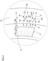
- the linear carrier elements 16 extend from the carrier surface 12 of the electrode carrier 10 in a direction normal to the carrier surface 12 into the retina 32, in particular into the ganglionic layer thereof. It can be seen that the electrodes 18 form a three-dimensional array distributed over a certain volume of the respective layer of the retina 32.
- a ganglionic cell 38a may be stimulated by using electrode 18a of one of the linear carrier elements 16 as a first, active electrode, and electrode 18b of another linear carrier element 16 as a ground electrode.
- a ganglionic cell 38b may be stimulated by using two or more first electrodes, for example 18c, 18d (possibly disposed on a certain linear carrier element 16 as shown, or disposed on different linear carrier elements 16) as first/active electrodes and two or more adjacent, second carrier electrodes for example 18e, 18f (possibly disposed on a certain linear carrier element 16 as shown, or disposed on different linear carrier elements 16) as ground electrodes.
- Current pulses indicated by small arrows may in each case lead to an activation of the targeted ganglionic cell 38a, 38b.
- this scheme gives the flexibility to select a desired stimulating pulse, for example charge-balanced biphasic rectangular pulse, and the require amplitude of electrical current for effective stimulation of retinal neurons.
- some of the electrodes 18 are positioned in a minimum distance 44 from the carrier surface 12, while other electrodes are positioned in a maximum distance 46 from the carrier surface 12.
- Figure 3 shows the elements of the enlarged section of Fig. 2 in a perspective view.
- the elements explained with regard to Fig. 2 are provided with the same reference numerals.
- the electronic carrier 10 and its carrier surface 12 have a generally rectangular shape, wherein the carrier surface 12 forms a part of a sphere to correspond to the shape of the retina 32.
- the various electrodes 18 are distributed over a three-dimensional volume.
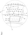
- FIG. 4 shows another electrode carrier 10 in a view similar to the view of Fig. 3 , that is in a perspective view when implanted into a human eye 24.
- each of the linear carrier elements 16 includes a holding segment 48 and an electrode segment 50, wherein only the electrode segment 50 carries the electrodes 18 which are again arranged in substantially regular intervals.
- the electrode segments 50 of Fig. 4 are oriented parallel to the carrier surface 12, so that the various electrodes 18 carried by one of the electrode segments 50 are all placed within approximately the same distance from the carrier surface 12.
- the embodiment of Fig. 4 exhibits a certain three-dimensional volume over which the electrodes 18 are distributed, again covering varying distances from the carrier surface 12. This gives the advantage of including different current paths along the ganglionic layer for the sake of activating single cells and improving visual perception.
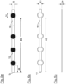
- Figs. 5a, 5b and 5c show views of top, bottom and side face of a linear carrier element 16 which carries a plurality of electrodes 18 intended to deliver current pulses to the underlying retinal ganglion cells for activation.
- the linear carrier elements 16 are connected to an electrode connecting point 14 of an electrode carrier 10, for example the electrode carrier 10 shown in figure 1 .
- the leftmost electrode 18 is disposed in minimum distance 44 from the carrier surface 12 or the electrode connecting point 14, respectively.
- the rightmost electrode 18 is disposed in a maximum distance 46 from the electrode carrier 10 or the carrier surface 12, respectively.
- Linear carrier element 16 may comprise a flexible material such as polymeric film with a small thickness 58 and/or a small width 52 compared to its length, in order to comply with bending requirements inside the ganglionic layer.
- State-of-the-art technology can realize a narrow width 52 of the linear carrier element 16 of around 1 ⁇ m with the proper conductive paths 62 and electrode connections 56.
- Extensive computer simulations analyzing activation areas at the surface of the retina suggested that an electrode diameter twice of the width, i.e. 2 ⁇ m, can deliver safe stimulus within a distance of 10 ⁇ m of the electrodes 18 from the relevant nervous cells.
- Figs. 5d, 5e and 5f show another linear carrier element 16 with similar features as discussed with regard to Figs. 5a, 5b and 5c .
- the electrodes 18 differ in their geometric shape which is not circular, but rectangular.
- the rectangular electrodes 18 have a width corresponding to the width 52 of the linear carrier element 16.
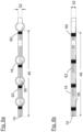
- Fig. 6a show the bottom perspective view of the linear carrier element 16 of Fig. 5a with a fixed number of conductive paths 62 connected to each of the decoding circuits 60 that select the corresponding electrode 18 which is connected via the electrode connection 56.
- This figure shows that each of the electrodes 18 is connected to the electrode connecting point 14 by means of a separate electrode connection 56 from a decoding circuit 60.
- the electrode connections 56 and conductive paths 62 are formed from small metallic conductive paths arranged at the bottom of the linear carrier element 16.
- Fig. 6b show another linear carrier element 16 with similar features as discussed with regard to Fig. 6a .
- the electrodes 18 differ in their geometrical shape which is not circular, but rectangular.
Landscapes
- Health & Medical Sciences (AREA)
- Ophthalmology & Optometry (AREA)
- Cardiology (AREA)
- Heart & Thoracic Surgery (AREA)
- Engineering & Computer Science (AREA)
- Biomedical Technology (AREA)
- Nuclear Medicine, Radiotherapy & Molecular Imaging (AREA)
- Radiology & Medical Imaging (AREA)
- Life Sciences & Earth Sciences (AREA)
- Animal Behavior & Ethology (AREA)
- General Health & Medical Sciences (AREA)
- Public Health (AREA)
- Veterinary Medicine (AREA)
- Prostheses (AREA)
- Electrotherapy Devices (AREA)
Claims (14)
- Retina-Implantat, umfassend:• einen Elektrodenträger (10), der eine zweidimensionale Trägeroberfläche (12) aufweist und zur chirurgischen Implantation innerhalb eines Auges angepasst ist, sodass die Trägeroberfläche (12) einer Schicht einer Retina (32) zugewandt ist,• eine Vielzahl von Elektroden (18), die an der Trägeroberfläche (12) angebracht sind, und• eine elektronische Steuereinrichtung (20), die mit den Elektroden (18) verbunden ist, zum Bereitstellen von Stimulationssignalen für die Elektroden (18), wobei• die Elektroden (18) in veränderlichen Abständen von der Trägeroberfläche (12) angeordnet sind, und wobei• die Trägeroberfläche (12) eine Vielzahl von Elektrodenverbindungspunkten (14) umfasst, die in einem Muster auf der Trägeroberfläche (12) angeordnet sind, wobei jeder der Elektrodenverbindungspunkte (14) mit mindestens einer der Elektroden (18) verbunden ist, gekennzeichnet durch• eine Vielzahl von linearen Trägerelementen (16), wobei jedes der linearen Trägerelemente (16) mit einem Elektrodenverbindungspunkt (14) verbunden ist und eine Vielzahl von den Elektroden (18) trägt.
- Retina-Implantat nach Anspruch 1, dadurch gekennzeichnet, dass mindestens eine der Elektroden (18) in einem Mindestabstand (44) von weniger als 10 µm von der Trägeroberfläche (12) positioniert ist.
- Retina-Implantat nach Anspruch 1 oder 2, dadurch gekennzeichnet, dass mindestens eine der Elektroden (18) in einem Höchstabstand (46) von größer als 50 µm von der Trägeroberfläche (12) positioniert ist.
- Retina-Implantat nach einem der Ansprüche 1 bis 3, dadurch gekennzeichnet, dass die linearen Trägerelemente (16) jeweils einen Draht umfassen, wobei die Vielzahl von den Elektroden (18), die von dem entsprechenden linearen Trägerelement (16) getragen werden, an dem Draht befestigt sind.
- Retina-Implantat nach einem der Ansprüche 1 bis 4, dadurch gekennzeichnet, dass jedes lineare Trägerelement (16) eine Vielzahl von Decodierungsschaltungen (60), wobei jede der Decodierungsschaltungen (60) einer der Elektroden (18) des entsprechenden linearen Trägerelements (16) zugewiesen ist, und eine feste Anzahl von Leiterbahnen (62) umfasst, die alle mit jeder der Decodierungsschaltungen (60) verbunden sind.
- Retina-Implantat nach einem der Ansprüche 1 bis 5, dadurch gekennzeichnet, dass die Elektroden (18) von mindestens einem von dem linearen Trägerelement (16) in gleichmäßigen Intervallen über ein Elektrodensegment (50) des entsprechenden linearen Trägerelements (16) verteilt sind.
- Retina-Implantat nach einem der Ansprüche 1 bis 6, dadurch gekennzeichnet, dass mindestens eines der Elektrodensegmente (50) in einer Richtung normal zur Trägeroberfläche (12) angeordnet ist.
- Retina-Implantat nach einem der Ansprüche 1 bis 7, dadurch gekennzeichnet, dass mindestens eines der Elektrodensegmente (50) in einem konstanten Abstand von der Trägeroberfläche (12) angeordnet ist.
- Retina-Implantat nach einem der Ansprüche 1 bis 8, dadurch gekennzeichnet, dass die Trägeroberfläche (12) einen Abschnitt einer Kugel bildet.
- Retina-Implantat nach einem der Ansprüche 1 bis 9, dadurch gekennzeichnet, dass der Elektrodenträger (10) eine biegsame Folie umfasst.
- Retina-Implantat nach einem der Ansprüche 1 bis 10, dadurch gekennzeichnet, dass die elektronische Steuereinrichtung (20) so angepasst ist, dass sie ein Stimulationssignal durch Anlegen eines Stromimpulses an mindestens eine erste Elektrode (18a, 18c, 18d) der Vielzahl von Elektroden (18) und durch Verbinden mindestens einer zweiten Elektrode (18b, 18e, 18f) der Vielzahl von Elektroden (18) mit der Masse bereitstellt.
- Retina-Implantat nach Anspruch 11, dadurch gekennzeichnet, dass die elektronische Steuereinrichtung (20) so angepasst ist, dass sie jede der Elektroden (18) als eine erste Elektrode (18a, 18c, 18d) und als eine zweite Elektrode (18b, 18e, 18f) verwendet.
- Retina-Implantat nach Anspruch 11 oder 12, dadurch gekennzeichnet, dass die erste Elektrode (18a, 18c, 18d) mit einem ersten Elektrodenverbindungspunkt (14) der Vielzahl von Elektrodenverbindungspunkten (14) verbunden ist und die zweite Elektrode (18b, 18e, 18f) mit einem zweiten Elektrodenverbindungspunkt (14) der Vielzahl von Elektrodenverbindungspunkten (14) verbunden ist.
- Retina-Implantat nach Anspruch 11 oder 12, dadurch gekennzeichnet, dass die erste und die zweite Elektrode mit demselben Elektrodenverbindungspunkt (14) verbunden sind.
Applications Claiming Priority (2)
| Application Number | Priority Date | Filing Date | Title |
|---|---|---|---|
| LU100467A LU100467B1 (en) | 2017-09-22 | 2017-09-22 | Retina implant |
| PCT/EP2018/074450 WO2019057551A1 (en) | 2017-09-22 | 2018-09-11 | RETINAL IMPLANT |
Publications (3)
| Publication Number | Publication Date |
|---|---|
| EP3684458A1 EP3684458A1 (de) | 2020-07-29 |
| EP3684458B1 true EP3684458B1 (de) | 2023-07-12 |
| EP3684458C0 EP3684458C0 (de) | 2023-07-12 |
Family
ID=60320956
Family Applications (1)
| Application Number | Title | Priority Date | Filing Date |
|---|---|---|---|
| EP18765132.8A Active EP3684458B1 (de) | 2017-09-22 | 2018-09-11 | Retina-implantat |
Country Status (4)
| Country | Link |
|---|---|
| EP (1) | EP3684458B1 (de) |
| ES (1) | ES2955288T3 (de) |
| LU (1) | LU100467B1 (de) |
| WO (1) | WO2019057551A1 (de) |
Family Cites Families (5)
| Publication number | Priority date | Publication date | Assignee | Title |
|---|---|---|---|---|
| EP1762269A3 (de) * | 1999-03-24 | 2007-05-23 | Second Sight Medical Products, Inc. | Sehprothese |
| US6389317B1 (en) | 2000-03-31 | 2002-05-14 | Optobionics Corporation | Multi-phasic microphotodetector retinal implant with variable voltage and current capability |
| US8260428B2 (en) | 2003-05-01 | 2012-09-04 | California Institute Of Technology | Method and system for training a visual prosthesis |
| US20080234791A1 (en) * | 2007-01-17 | 2008-09-25 | Jeffrey Edward Arle | Spinal cord implant systems and methods |
| US8442641B2 (en) * | 2010-08-06 | 2013-05-14 | Nano-Retina, Inc. | Retinal prosthesis techniques |
-
2017
- 2017-09-22 LU LU100467A patent/LU100467B1/en active IP Right Grant
-
2018
- 2018-09-11 WO PCT/EP2018/074450 patent/WO2019057551A1/en not_active Ceased
- 2018-09-11 EP EP18765132.8A patent/EP3684458B1/de active Active
- 2018-09-11 ES ES18765132T patent/ES2955288T3/es active Active
Also Published As
| Publication number | Publication date |
|---|---|
| EP3684458A1 (de) | 2020-07-29 |
| LU100467B1 (en) | 2019-03-29 |
| ES2955288T3 (es) | 2023-11-29 |
| WO2019057551A1 (en) | 2019-03-28 |
| EP3684458C0 (de) | 2023-07-12 |
Similar Documents
| Publication | Publication Date | Title |
|---|---|---|
| US6718209B2 (en) | Retinal prosthesis with remote return electrode | |
| US9302107B2 (en) | Cortical visual prosthesis | |
| US20060042830A1 (en) | Flexible multi-level cable | |
| Weiland et al. | Retinal prosthesis | |
| EP2192949B1 (de) | Neutralelektrode für elektrodenanordnung einer flexiblen schaltung | |
| CN109364368B (zh) | 人工视网膜的刺激电极结构及人工视网膜 | |
| JP4945046B2 (ja) | 神経網膜の両側に刺激電極および接地帰路電極が配置された人工網膜装置およびその装着方法 | |
| US8180453B2 (en) | Electrode array for neural stimulation | |
| EP2219728B1 (de) | Elektrodenanordnung für gleichmässigen neuralen druck mit mehreren befestigungspunkten | |
| US7894911B2 (en) | Electrode array for neural stimulation | |
| AU2003220590B2 (en) | Variable pitch electrode array | |
| JP4393029B2 (ja) | 可変電圧電流能を備えた多相式マイクロ光電検出装置による網膜移植法と挿入用装置 | |
| US7499754B2 (en) | Retinal prosthesis | |
| US7035692B1 (en) | High density polymer-based integrated electrode array | |
| US9037252B2 (en) | Visual prosthesis and retina stimulation device for same | |
| EP2523598A2 (de) | Eindringungselektroden zur retina-stimulation | |
| JP2005516705A (ja) | マイクロ電子刺激装置アレイ | |
| EP1983936A2 (de) | Weitsicht-retinaprothese | |
| CN106362279A (zh) | 刺激电极结构及人工视网膜的植入装置 | |
| Suaning et al. | Neuromodulation of the retina from the suprachoroidal space: the Phoenix 99 implant | |
| JP4310247B2 (ja) | 視覚再生補助装置 | |
| EP3684458B1 (de) | Retina-implantat | |
| US20060224212A1 (en) | Neural electrode array | |
| Noda et al. | Fabrication of fork-shaped retinal stimulator integrated with CMOS microchips for extension of viewing angle | |
| CN206198475U (zh) | 人工视网膜的刺激电极结构及人工视网膜 |
Legal Events
| Date | Code | Title | Description |
|---|---|---|---|
| STAA | Information on the status of an ep patent application or granted ep patent |
Free format text: STATUS: UNKNOWN |
|
| STAA | Information on the status of an ep patent application or granted ep patent |
Free format text: STATUS: THE INTERNATIONAL PUBLICATION HAS BEEN MADE |
|
| PUAI | Public reference made under article 153(3) epc to a published international application that has entered the european phase |
Free format text: ORIGINAL CODE: 0009012 |
|
| STAA | Information on the status of an ep patent application or granted ep patent |
Free format text: STATUS: REQUEST FOR EXAMINATION WAS MADE |
|
| 17P | Request for examination filed |
Effective date: 20200407 |
|
| AK | Designated contracting states |
Kind code of ref document: A1 Designated state(s): AL AT BE BG CH CY CZ DE DK EE ES FI FR GB GR HR HU IE IS IT LI LT LU LV MC MK MT NL NO PL PT RO RS SE SI SK SM TR |
|
| AX | Request for extension of the european patent |
Extension state: BA ME |
|
| RIN1 | Information on inventor provided before grant (corrected) |
Inventor name: LUJAN VILLARREAL, DIEGO Inventor name: KRAUTSCHNEIDER, WOLFGANG Inventor name: SCHROEDER, DIETMAR |
|
| DAV | Request for validation of the european patent (deleted) | ||
| DAX | Request for extension of the european patent (deleted) | ||
| GRAP | Despatch of communication of intention to grant a patent |
Free format text: ORIGINAL CODE: EPIDOSNIGR1 |
|
| STAA | Information on the status of an ep patent application or granted ep patent |
Free format text: STATUS: GRANT OF PATENT IS INTENDED |
|
| RIC1 | Information provided on ipc code assigned before grant |
Ipc: A61N 1/36 20060101ALN20230222BHEP Ipc: A61N 1/05 20060101AFI20230222BHEP |
|
| INTG | Intention to grant announced |
Effective date: 20230316 |
|
| GRAS | Grant fee paid |
Free format text: ORIGINAL CODE: EPIDOSNIGR3 |
|
| GRAA | (expected) grant |
Free format text: ORIGINAL CODE: 0009210 |
|
| STAA | Information on the status of an ep patent application or granted ep patent |
Free format text: STATUS: THE PATENT HAS BEEN GRANTED |
|
| AK | Designated contracting states |
Kind code of ref document: B1 Designated state(s): AL AT BE BG CH CY CZ DE DK EE ES FI FR GB GR HR HU IE IS IT LI LT LU LV MC MK MT NL NO PL PT RO RS SE SI SK SM TR |
|
| REG | Reference to a national code |
Ref country code: CH Ref legal event code: EP |
|
| REG | Reference to a national code |
Ref country code: IE Ref legal event code: FG4D |
|
| REG | Reference to a national code |
Ref country code: DE Ref legal event code: R096 Ref document number: 602018053232 Country of ref document: DE |
|
| U01 | Request for unitary effect filed |
Effective date: 20230724 |
|
| U07 | Unitary effect registered |
Designated state(s): AT BE BG DE DK EE FI FR IT LT LU LV MT NL PT SE SI Effective date: 20230727 |
|
| U20 | Renewal fee for the european patent with unitary effect paid |
Year of fee payment: 6 Effective date: 20230918 |
|
| REG | Reference to a national code |
Ref country code: LT Ref legal event code: MG9D |
|
| REG | Reference to a national code |
Ref country code: ES Ref legal event code: FG2A Ref document number: 2955288 Country of ref document: ES Kind code of ref document: T3 Effective date: 20231129 |
|
| PG25 | Lapsed in a contracting state [announced via postgrant information from national office to epo] |
Ref country code: GR Free format text: LAPSE BECAUSE OF FAILURE TO SUBMIT A TRANSLATION OF THE DESCRIPTION OR TO PAY THE FEE WITHIN THE PRESCRIBED TIME-LIMIT Effective date: 20231013 |
|
| PG25 | Lapsed in a contracting state [announced via postgrant information from national office to epo] |
Ref country code: IS Free format text: LAPSE BECAUSE OF FAILURE TO SUBMIT A TRANSLATION OF THE DESCRIPTION OR TO PAY THE FEE WITHIN THE PRESCRIBED TIME-LIMIT Effective date: 20231112 |
|
| PG25 | Lapsed in a contracting state [announced via postgrant information from national office to epo] |
Ref country code: RS Free format text: LAPSE BECAUSE OF FAILURE TO SUBMIT A TRANSLATION OF THE DESCRIPTION OR TO PAY THE FEE WITHIN THE PRESCRIBED TIME-LIMIT Effective date: 20230712 Ref country code: NO Free format text: LAPSE BECAUSE OF FAILURE TO SUBMIT A TRANSLATION OF THE DESCRIPTION OR TO PAY THE FEE WITHIN THE PRESCRIBED TIME-LIMIT Effective date: 20231012 Ref country code: IS Free format text: LAPSE BECAUSE OF FAILURE TO SUBMIT A TRANSLATION OF THE DESCRIPTION OR TO PAY THE FEE WITHIN THE PRESCRIBED TIME-LIMIT Effective date: 20231112 Ref country code: HR Free format text: LAPSE BECAUSE OF FAILURE TO SUBMIT A TRANSLATION OF THE DESCRIPTION OR TO PAY THE FEE WITHIN THE PRESCRIBED TIME-LIMIT Effective date: 20230712 Ref country code: GR Free format text: LAPSE BECAUSE OF FAILURE TO SUBMIT A TRANSLATION OF THE DESCRIPTION OR TO PAY THE FEE WITHIN THE PRESCRIBED TIME-LIMIT Effective date: 20231013 |
|
| PG25 | Lapsed in a contracting state [announced via postgrant information from national office to epo] |
Ref country code: PL Free format text: LAPSE BECAUSE OF FAILURE TO SUBMIT A TRANSLATION OF THE DESCRIPTION OR TO PAY THE FEE WITHIN THE PRESCRIBED TIME-LIMIT Effective date: 20230712 |
|
| REG | Reference to a national code |
Ref country code: DE Ref legal event code: R097 Ref document number: 602018053232 Country of ref document: DE |
|
| PG25 | Lapsed in a contracting state [announced via postgrant information from national office to epo] |
Ref country code: SM Free format text: LAPSE BECAUSE OF FAILURE TO SUBMIT A TRANSLATION OF THE DESCRIPTION OR TO PAY THE FEE WITHIN THE PRESCRIBED TIME-LIMIT Effective date: 20230712 Ref country code: RO Free format text: LAPSE BECAUSE OF FAILURE TO SUBMIT A TRANSLATION OF THE DESCRIPTION OR TO PAY THE FEE WITHIN THE PRESCRIBED TIME-LIMIT Effective date: 20230712 Ref country code: CZ Free format text: LAPSE BECAUSE OF FAILURE TO SUBMIT A TRANSLATION OF THE DESCRIPTION OR TO PAY THE FEE WITHIN THE PRESCRIBED TIME-LIMIT Effective date: 20230712 Ref country code: SK Free format text: LAPSE BECAUSE OF FAILURE TO SUBMIT A TRANSLATION OF THE DESCRIPTION OR TO PAY THE FEE WITHIN THE PRESCRIBED TIME-LIMIT Effective date: 20230712 |
|
| REG | Reference to a national code |
Ref country code: CH Ref legal event code: PL |
|
| PLBE | No opposition filed within time limit |
Free format text: ORIGINAL CODE: 0009261 |
|
| STAA | Information on the status of an ep patent application or granted ep patent |
Free format text: STATUS: NO OPPOSITION FILED WITHIN TIME LIMIT |
|
| PG25 | Lapsed in a contracting state [announced via postgrant information from national office to epo] |
Ref country code: MC Free format text: LAPSE BECAUSE OF FAILURE TO SUBMIT A TRANSLATION OF THE DESCRIPTION OR TO PAY THE FEE WITHIN THE PRESCRIBED TIME-LIMIT Effective date: 20230712 |
|
| 26N | No opposition filed |
Effective date: 20240415 |
|
| REG | Reference to a national code |
Ref country code: IE Ref legal event code: MM4A |
|
| PG25 | Lapsed in a contracting state [announced via postgrant information from national office to epo] |
Ref country code: IE Free format text: LAPSE BECAUSE OF NON-PAYMENT OF DUE FEES Effective date: 20230911 |
|
| PG25 | Lapsed in a contracting state [announced via postgrant information from national office to epo] |
Ref country code: CH Free format text: LAPSE BECAUSE OF NON-PAYMENT OF DUE FEES Effective date: 20230930 |
|
| PG25 | Lapsed in a contracting state [announced via postgrant information from national office to epo] |
Ref country code: IE Free format text: LAPSE BECAUSE OF NON-PAYMENT OF DUE FEES Effective date: 20230911 Ref country code: CH Free format text: LAPSE BECAUSE OF NON-PAYMENT OF DUE FEES Effective date: 20230930 |
|
| U20 | Renewal fee for the european patent with unitary effect paid |
Year of fee payment: 7 Effective date: 20240904 |
|
| PG25 | Lapsed in a contracting state [announced via postgrant information from national office to epo] |
Ref country code: CY Free format text: LAPSE BECAUSE OF FAILURE TO SUBMIT A TRANSLATION OF THE DESCRIPTION OR TO PAY THE FEE WITHIN THE PRESCRIBED TIME-LIMIT; INVALID AB INITIO Effective date: 20180911 |
|
| PG25 | Lapsed in a contracting state [announced via postgrant information from national office to epo] |
Ref country code: HU Free format text: LAPSE BECAUSE OF FAILURE TO SUBMIT A TRANSLATION OF THE DESCRIPTION OR TO PAY THE FEE WITHIN THE PRESCRIBED TIME-LIMIT; INVALID AB INITIO Effective date: 20180911 |
|
| U20 | Renewal fee for the european patent with unitary effect paid |
Year of fee payment: 8 Effective date: 20250903 |
|
| PGFP | Annual fee paid to national office [announced via postgrant information from national office to epo] |
Ref country code: GB Payment date: 20250717 Year of fee payment: 8 |
|
| PG25 | Lapsed in a contracting state [announced via postgrant information from national office to epo] |
Ref country code: TR Free format text: LAPSE BECAUSE OF FAILURE TO SUBMIT A TRANSLATION OF THE DESCRIPTION OR TO PAY THE FEE WITHIN THE PRESCRIBED TIME-LIMIT Effective date: 20230712 |
|
| PGFP | Annual fee paid to national office [announced via postgrant information from national office to epo] |
Ref country code: ES Payment date: 20251029 Year of fee payment: 8 |