EP3684429B1 - Vorrichtung und verfahren zur verhinderung von biofouling - Google Patents
Vorrichtung und verfahren zur verhinderung von biofouling Download PDFInfo
- Publication number
- EP3684429B1 EP3684429B1 EP18855319.2A EP18855319A EP3684429B1 EP 3684429 B1 EP3684429 B1 EP 3684429B1 EP 18855319 A EP18855319 A EP 18855319A EP 3684429 B1 EP3684429 B1 EP 3684429B1
- Authority
- EP
- European Patent Office
- Prior art keywords
- duration
- high power
- power value
- low power
- image
- Prior art date
- Legal status (The legal status is an assumption and is not a legal conclusion. Google has not performed a legal analysis and makes no representation as to the accuracy of the status listed.)
- Active
Links
Images

Classifications
-
- B—PERFORMING OPERATIONS; TRANSPORTING
- B08—CLEANING
- B08B—CLEANING IN GENERAL; PREVENTION OF FOULING IN GENERAL
- B08B7/00—Cleaning by methods not provided for in a single other subclass or a single group in this subclass
- B08B7/0035—Cleaning by methods not provided for in a single other subclass or a single group in this subclass by radiant energy, e.g. UV, laser, light beam or the like
- B08B7/0057—Cleaning by methods not provided for in a single other subclass or a single group in this subclass by radiant energy, e.g. UV, laser, light beam or the like by ultraviolet radiation
-
- B—PERFORMING OPERATIONS; TRANSPORTING
- B08—CLEANING
- B08B—CLEANING IN GENERAL; PREVENTION OF FOULING IN GENERAL
- B08B17/00—Methods preventing fouling
- B08B17/02—Preventing deposition of fouling or of dust
-
- G—PHYSICS
- G02—OPTICS
- G02B—OPTICAL ELEMENTS, SYSTEMS OR APPARATUS
- G02B19/00—Condensers, e.g. light collectors or similar non-imaging optics
- G02B19/0033—Condensers, e.g. light collectors or similar non-imaging optics characterised by the use
- G02B19/0095—Condensers, e.g. light collectors or similar non-imaging optics characterised by the use for use with ultraviolet radiation
-
- G—PHYSICS
- G02—OPTICS
- G02B—OPTICAL ELEMENTS, SYSTEMS OR APPARATUS
- G02B27/00—Optical systems or apparatus not provided for by any of the groups G02B1/00 - G02B26/00, G02B30/00
- G02B27/0006—Optical systems or apparatus not provided for by any of the groups G02B1/00 - G02B26/00, G02B30/00 with means to keep optical surfaces clean, e.g. by preventing or removing dirt, stains, contamination, condensation
-
- G—PHYSICS
- G03—PHOTOGRAPHY; CINEMATOGRAPHY; ANALOGOUS TECHNIQUES USING WAVES OTHER THAN OPTICAL WAVES; ELECTROGRAPHY; HOLOGRAPHY
- G03B—APPARATUS OR ARRANGEMENTS FOR TAKING PHOTOGRAPHS OR FOR PROJECTING OR VIEWING THEM; APPARATUS OR ARRANGEMENTS EMPLOYING ANALOGOUS TECHNIQUES USING WAVES OTHER THAN OPTICAL WAVES; ACCESSORIES THEREFOR
- G03B15/00—Special procedures for taking photographs; Apparatus therefor
- G03B15/02—Illuminating scene
- G03B15/03—Combinations of cameras with lighting apparatus; Flash units
-
- G—PHYSICS
- G03—PHOTOGRAPHY; CINEMATOGRAPHY; ANALOGOUS TECHNIQUES USING WAVES OTHER THAN OPTICAL WAVES; ELECTROGRAPHY; HOLOGRAPHY
- G03B—APPARATUS OR ARRANGEMENTS FOR TAKING PHOTOGRAPHS OR FOR PROJECTING OR VIEWING THEM; APPARATUS OR ARRANGEMENTS EMPLOYING ANALOGOUS TECHNIQUES USING WAVES OTHER THAN OPTICAL WAVES; ACCESSORIES THEREFOR
- G03B17/00—Details of cameras or camera bodies; Accessories therefor
- G03B17/02—Bodies
- G03B17/08—Waterproof bodies or housings
-
- G—PHYSICS
- G03—PHOTOGRAPHY; CINEMATOGRAPHY; ANALOGOUS TECHNIQUES USING WAVES OTHER THAN OPTICAL WAVES; ELECTROGRAPHY; HOLOGRAPHY
- G03B—APPARATUS OR ARRANGEMENTS FOR TAKING PHOTOGRAPHS OR FOR PROJECTING OR VIEWING THEM; APPARATUS OR ARRANGEMENTS EMPLOYING ANALOGOUS TECHNIQUES USING WAVES OTHER THAN OPTICAL WAVES; ACCESSORIES THEREFOR
- G03B2215/00—Special procedures for taking photographs; Apparatus therefor
- G03B2215/05—Combinations of cameras with electronic flash units
- G03B2215/0564—Combinations of cameras with electronic flash units characterised by the type of light source
- G03B2215/0567—Solid-state light source, e.g. LED, laser
Definitions
- biofouling refers to the accumulation of microorganisms, plants, algae, or animals on surfaces.
- methods to reduce or eliminate biofouling involved the use of biocidal compounds in paints or other coatings applied to exposed surfaces. Such coatings wear off over time and are subject to spallation, cracking and other imperfections, and are not suitable for many applications.
- UV LEDs ultra violet light emitting diodes
- UV LEDs such as those comprising aluminum nitride
- Another example of the use of UV light to prevent biofouling is described in U.S. Patent No. 9,235,048 and related US Publication No. 2016/0121009 .
- UV light sources used with these apparatuses are situated outside of their housings, such that the light source is positioned in front of the window such that water is within the space between the light source and the window.
- the light sources may at least partly obstruct the view.
- parts of the window may also be in the shade of mounting brackets used in these apparatuses, and biofouling may still occur in these shadowed areas.
- the UV intensity may be attenuated by travelling through the water.
- Document US2012/050520 provides another example of prior art method and system for reducing biofouling in a marine environment and discloses a method for reducing biofouling in a marine environment in accordance with the preamble of claim 1 and an apparatus suitable for reducing biofouling in a marine environment in accordance with the preamble of claim 11.
- An example of a method for reducing biofouling in a marine environment includes disposing an optical device in the marine environment, wherein the optical device is directed at an object in the marine environment, obtaining an image of the object with the optical device, determining a quality of the image, determining a high power value and a high power duration based on the quality of the image, determining a low power value and a low power duration based on the quality of the image, and activate at least one ultraviolet light source for a plurality of cycles based on the high power value, the high power duration, the low power value and the low power duration, wherein the at least one ultraviolet light source is disposed proximate to the optical device and directed at the object.
- UV power at the wavelength of the LED and the electrical power required to generate this UV power.
- an electrical-to-UV-C conversion efficiency of 1% is attained with current LED technologies.
- power specifications used herein are labeled with electrical or UV units.
- At least one ultraviolet light source may be characterized by emission wavelength of between 250 nanometers and 400 nanometers.
- the flash duration may be between 0.01 seconds and 1000 seconds.
- the flash power value may be between 1 milliwatt (UV) and 100 milliwatts (UV).
- the rest power value may be less than 1 milliwatt.
- the rest duration may be between 1 second and 100,000 seconds.
- the flash power value, the flash duration, the rest power value and the rest duration may be provided to a server.
- the flash power value, the flash duration, the rest power value and the rest duration may be received from a server.
- An example of an apparatus for reducing biofouling in a marine environment includes a housing including a cavity and an ultraviolet transparent window disposed over the cavity, an optical device disposed in the cavity and directed towards the ultraviolet transparent window, one or more ultraviolet light emitting diodes disposed in the cavity and directed toward the ultraviolet transparent window, and a controller operably coupled to the one or more ultraviolet light emitting diodes and configured to provide at least one lamp power function to the one or more ultraviolet light emitting diodes, obtain an image of an object in the marine environment, determine a quality of the image, and activate at least one ultraviolet light emitting diode for a plurality of cycles based on a high power value, a high power duration, a low power value and a low power duration.
- a lamp power function is the representation of the electrical power applied to the UV LED over time.
- the ultraviolet transparent window may be constructed at least in part with at least one material selected from a group consisting of sapphire, silicon carbide (SiC), diamond, zinc sulfide (ZnS), zinc selenide (ZnSe), Barium fluoride (BaF2), aluminum dioxide (Al203), quartz (SiO2), and magnesium fluoride (MgF2).
- At least one of the one or more ultraviolet light emitting diodes may be characterized by emission wavelengths between 250 nanometer and 400 nanometers.
- a power source may be operably coupled to the one or more ultraviolet light emitting diodes.
- the controller may be configured to receive the at least one lamp power function from a remote server.
- the controller may include at least one data structure configured to store the at least one lamp power function.
- the flash duration may be between 0.01 seconds and 1000 seconds and the flash power value may be between 1 milliwatt (UV) and 100 milliwatts (UV).
- the rest power value may be less than 10 milliwatts and the rest duration may be between 1 second and 100,000 seconds.
- the flash power value may be approximately 12.5 milliwatts (UV), the flash duration is approximately 0.1 seconds, the rest power value may be less than 0.001 milliwatts (UV), and the rest duration is approximately 19.9 seconds.
- An example of an apparatus includes a housing means including a cavity configured to enclose one or more optical device means and one or more ultraviolet light emitting means, an ultraviolet transparent window means disposed on the housing means over the cavity, such that the one or more optical device means and the one or more ultraviolet light emitting means are directed towards the ultraviolet transparent window means, and a controller means operably coupled to the one or more ultraviolet light emitting means and configured to provide at least one lamp power function to the one or more ultraviolet light emitting means, such that the at least one lamp power function is based on at least a flash power value, a flash duration, a rest power value and a rest duration.
- An optical sensing device may be placed behind a window in a marine environment.
- the window may be a transparent or semi-transparent component through which light is passed.
- An ultraviolet (UV) light source may be directed at the
- a programmable controller may be operably coupled to the UV light source and configured to cyclically activate the UV light source using two or more periods at varying power levels.
- a cycle may include a short high-power UV light flash, followed by a relatively longer period of relatively low power UV light or no UV light.
- the cyclical operation may reduce the power consumed by the controller.
- the reduced power consumption may extend the operational service life of the optical sensing device.
- Other capabilities may be provided and not every implementation according to the disclosure must provide any, let alone all, of the capabilities discussed. Further, it may be possible for an effect noted above to be achieved by means other than that noted, and a noted item/technique may not necessarily yield the noted effect.
- Claims 1 and 11 respectively define a method and an apparatus in accordance with the invention.
- an optical sensor may be disposed in an apparatus that includes a window used for underwater applications.
- the container and window may be operable under a pressure of up to 10,000m of water.
- a method to keep the window substantially clear and free from biofouling includes using two or more periods of UV radiation with varying power. The sequence of these periods as defined by duration and UV power comprises a cycle.
- a cycle repeats itself indefinitely.
- one cycle may comprise a short, high power UV light (i.e., a flash), followed by a relatively longer period of relatively lower power UV light or no UV light.
- window refers to any transparent or semi- transparent component through which light is passed.
- the optical sensor and window apparatus may be utilized in underwater environments, such as underwater optical sensors, underwater cameras and underwater lights. They may also be used to expose deep sea environments to UV light, where such light would otherwise never be found.
- the window apparatus may be suitable for other related applications, such as curing materials extruded into the deep-water environment and forming structures needed outside of a vessel.
- the apparatus may use less than 20mW electrical power (continuous), preferably less than 10mW (electrical, continuous) and even more preferably less than 5mW (electrical, continuous).
- continuous power refers to the energy consumed during all periods of one entire cycle divided by the duration of that entire cycle.
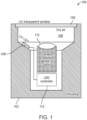
- the apparatus includes a housing 102, a UV transparent window 104, a device cavity 106, one or more UV light emitting diodes (LEDs) 108, an optical device 110, and a controller 112.
- the housing 102 may be a cylindrical housing that is open on one end. Other shapes and configurations may also be used. In general, the housing 102 may be constructed from suitable materials to withstand an underwater environment and corresponding mechanical forces to which it will be subjected.
- the housing 102 includes the device cavity 106 configured to accommodate one or more optical devices 110.
- the cavity 106 may optionally be filled with dry air, substantially pure nitrogen, argon and/or other inert gas.
- the opening on the housing 102 is fitted with a leak-tight window 104 comprising one or more UV-transparent materials.
- the housing 102 includes an internal arrangement of one or more UV LEDs 108 configured to project light onto the window 104.
- the UV LEDs 108 are characterized by emission wavelengths of between 250 - 400nm, preferably around 275nm.
- individual UV LEDs 108 may be configured to emit the same or different wavelengths in the same apparatus.
- the UV LEDs 108 are operably coupled to a power source (not shown in FIG. 1 ) and the controller 112.
- Power source may be an internal source (e.g., a battery) or an external source (e.g., via a water-tight connector in the housing 102).
- Inductive charging (e.g., wireless) techniques may also be used to charge the internal battery.
- the housing 102 further encloses one or more optical devices 110 and equipment as necessary for its application, such as a camera, an optical sensor, a lamp or simply the UV LEDs 108 only.
- the spatial arrangement of the UV LEDs 108 can be used to control the UV intensity distribution in the water-facing surface of the window.
- the intensity distribution can be designed depending on the intended use. For example, the UV intensity distribution is uniform across the window in some embodiments, while in other embodiments, the UV intensity is highest in the center of the window, while in still other embodiments, the UV intensity is highest around the window annulus.
- the UV LEDs 108 are configured to irradiate the UV transparent window 104 from the inside of the housing 102. That is, the UV LEDs 108 are orientated in the same general direction as the optical device 110 (e.g., both are directed toward an object). Additionally, in contrast to apparatuses of the prior art that project UV light from the outside of associated housings through water with attenuates UV light, the internal UV LED configurations of the present invention offer many advantages such as a reduction in energy consumption because UV light does not travel through water. The internal UV LEDs do not require external structures to support a light source, which may protrude from the outside surface of the housing and thus increase drag on an underwater apparatus.
- the window 104 may be made flush with the surface of the housing 102 and the UV LEDs 108 can be installed inside the same watertight device cavity 106 that protects the optical devices 110 (e.g., cameras and other components within the apparatus), thus reducing complexity.
- the optical devices 110 e.g., cameras and other components within the apparatus
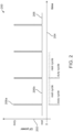
- the graph 200 includes a lamp power axis 202, a time axis 204 and a lamp power function 206.
- the UV LEDs 108 is/are driven by controller 112 that is configured to apply a timed sequence of power to the UV LEDs 108.
- the timed sequence may be a lamp power function 206 that includes a number of periods of varying power and duration, i.e., a complete cycle.
- the sequence is a period of relatively higher power 206a followed by a period of relatively lower power 206b, as schematically depicted in FIG. 2 .
- the duration of the higher power period may be in a range from 0.01 seconds to 1,000 seconds.
- the power applied during the duty period may be between 0.01x and 10.0x of the maximum rated continuous output of the UV LEDs 108, and the duration of the lower power period ("rest period") may range from 1 second to 100,000 seconds.
- the cycle profile - or the sequence of periods - may be tailored for specific marine biofouling environments.
- the power applied during the rest cycle is between 0.001x and 1.0x of the maximum rated continuous output of the LED.
- Commercially available UV LEDs e.g., Klaran LED by Crystal-IS
- the controller 112 may be configured to provide a power function to each of the UV LEDs 108 individually, as a group, or combinations therein.
- the controller 112 may be configured to supply different lamp power functions to different UV LEDs 108 or different groups of UV LEDs 108.
- UV LEDs 108 generate(s) a high intensity of UV light energy at the window 104 surface in contact with seawater, thus producing a high concentration of biocidal chemical agents on and near the window surface.
- the UV transparent window 104 may be comprised of specialty window materials, which work together with the UV light to lower the UV dosage required for biofouling reduction or elimination.
- window materials which work together with the UV light to lower the UV dosage required for biofouling reduction or elimination.
- Such embodiments make use of windows that are substantially optically clear but have outer surfaces that are modified to contain atoms or compounds of metals such as silver, copper, tin and/or lead.
- the UV LEDs 108 activates biocidal effects in these metals, which do not leach into surrounding water. Thus, there is no environmental damage and no deterioration of the effect over time.
- the water-facing surface of the window may be mechanically modified to provide additional anti-biofouling properties; such as, for example, being engraved with a micro pattern of a periodicity of 500 to 10,000 nm.
- the controller 112 may include one or more processors and associated memory devices configured to provide a voltage signal to the UV LEDs 108.
- the controller 112 may include a micro control unit (MCU) like an Attiny-85 by Microchip and suitable electronic components to control different temporal patterns and UV power settings to establish multiple irradiation modes for one or more UV LEDs 108.
- Example modes include continuous and pulsed UV irradiation. Under both such modes, the UV power can be selected.
- flash intensity and duration values may be determined based on the marine environment.
- rest intensity and duration values may be determined. The intensity and duration values may vary cycle to cycle and need not be constant (i.e., sinusoidal, sawtooth or other signal profiles may be used for the flash and rest periods).
- the controller 112 may be internal to the housing or external and coupled to the UV LEDs 108 via a waterproof coupler (not shown in FIG. 1 ).
- the controller 112 may be configured to provide control for both the power and timing of all UV LEDs 108 individually or collectively.
- the apparatus may comprise several UV LEDs 108 of different wavelengths.
- the controller 112 may be configured to provide each individual UV LED 108 with its own individual control signal to enable a temporal light pattern.
- the materials used to make the housing 102 may be electrically conductive, in which case the housing 102 can be used as an electrode for the UV LEDs 108.
- Example materials for the housing 102 include, but are not limited to, stainless-steel, copper, biocidally treated PVC, ABS and PE, ceramics such as SiN, A1203, BN, porcelain, glass and fiberglass. These materials may be treated to minimize biofouling, such as by coating or integration of anti-biofouling materials.
- a stainless-steel housing could be copper clad.
- Polymer materials may be infused with nanoparticles that are known to prevent biofouling. Other antifouling techniques may also be used on the exterior surface of the housing 102.
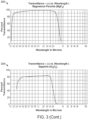
- the UV transparent window 104 may be constructed from materials such as, for example, sapphire, silicon carbide (SiC), diamond, zinc sulfide (ZnS), zinc selenide (ZnSe), Barium fluoride (BaF2), aluminum dioxide (Al2O3), quartz (SiO2), magnesium fluoride (MgF2), and other UV transparent materials.
- the UV transparent window 104 may be a composite of different materials such as the result of chemical or plasma vapor deposition process. The transmission properties of some of these materials are graphically illustrated in FIG. 3 .
- a first graph 302 illustrates the transmittance versus wavelength for Barium Fluoride.
- a second graph 304 illustrates the transmittance versus wavelength for Silicon Dioxide.
- a third graph 306 illustrates the transmittance versus wavelength for Magnesium Fluoride.
- a fourth graph 308 illustrates the transmittance versus wavelength for Sapphire.
- a combination of these materials and/or multiple windows may be required for requisite mechanical strength for deep sea applications.
- the embodiments of the UV transparent window 104 are characterized by mechanical strengths suitable for water pressures from 0 to 100 MPa (0 - 10,000m water column). Thick windows from water soluble material like MgF2 with high UV transparency and adequate mechanical strength may be combined with a thin sapphire or quartz protective window.
- a hydrophobic coating (e.g., Al2O3) may be applied to the exterior of the UV transparent window 104 to help reduce biofouling.
- the exterior coating on the UV transparent window 104 may be the result of an atomic layer deposition process to produce an atomically smooth surface in an effort to reduce biofouling on the exterior surface.
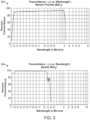
- a first test results graph 400 includes a fluorescence axis 402, a light wavelength axis 404, a first control curve 406, and a results curve 408.
- the fluorescence axis 402 is expressed in arbitrary units to show the fluorescence emission intensity of chlorophyll buildup on a control window in an underwater marine environment.
- the apparatus 100 may be used as a fouling resistant fluorometer. That is, the optical sensor 110 may be configured to measure the fluorescence of seawater and the control curve 406 and the results curve 408 represent measure of fluorescence at the indicated wavelengths.
- the control curve 406 shows the results of a window placed in a marine environment that was not irradiated by a UV source.
- the control curve 406 indicates the formation of chlorophyll (e.g., the appearance of the chlorophyll emission) on the control window material.
- the formation of chlorophyll is an early indicator for the onset of biofouling, because biofouling communities include algae and cyanobacteria that produce chlorophyll.
- the results curve 408 illustrates the results of illuminating an identical window in the same marine environment as the control window with the UV LEDs 108.
- the results curve 408 indicates the absence of chlorophyll formation on the window that was irradiated with 40mW (285UV) (400mA) for 0.1sec - the flash intensity and duration 206a - followed by darkness (or 10e-12mW for the low intensity cycle) for 19.9sec - the rest intensity and duration 206b.
- Summation of the energies used during the periods and division by the sum of durations of the periods provides the equivalent of 200 microwatt - of 285UV continuous or - considering an electrical to UV conversion efficiency of 1% of state-of-the-art UV LEDs - 20mW electrical continuous.
- a second test results graph 420 includes the fluorescence axis 402, the light wavelength axis 404, a second control curve 422, a 5-microwatt results curve 424, and a 12.5-microwatt results curve 426.
- the control curve 422 shows the results of a window placed in a marine environment that was not irradiated by a UV source.
- the control curve 422 indicates the formation of chlorophyllon the control window material.
- the 5-microwatt results curve 424 and the 12.5-microwatt results curve 426 illustrates the results of illuminating an identical window in the same marine environment as the control window with the UV LEDs 108.
- the 5-microwatt continuous (averaged) results curve 424 indicates a relatively less amount of chlorophyll formation on a window that was irradiated with 1mW (285UV) (10mA current) for 0.1sec (e.g., the flash intensity and duration 206a), followed by darkness (or 10e-12mW for the low intensity cycle) for 19.9sec (e.g., the rest intensity and duration 206b).
- the 12.5-microwatt continuous (averaged) results curve 426 indicates no amount of chlorophyll formation on a window that was irradiated with approximatley 2.5 mW (285UV) (25 mA current) for 0.1sec followed by darkness of 19.9 sec, or 12.5 ⁇ W integrated UVC.
- the 12.5-microwatt results curve 426 illustrates that a virtual elimination of biofouling may be achieved with much less power as required by other light-based biofouling solutions and as expected by those skilled in the art.
- the flash and rest intensity and duration values are examples only as other values may be used based on the marine environment and operational application of the apparatus 100.
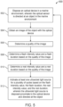
- a method 500 of determining a lamp duty cycle includes the stage shown.
- the method 500 is, however, an example only and not limiting.
- the method 500 may be altered, e.g., by having stages added, removed, rearranged, combined, performed concurrently, and/or having single stages split into multiple stages.
- stages 508 and 510 for determining the flash and rest intensity and duration values may be combined into a single stage. Still other alterations to the method 500 as shown and described are possible.
- the method includes disposing an optical device in a marine environment, such that the optical device is directed at an object in the marine environment.
- the optical device 110 may be located within the device cavity 106 in the housing 102 and behind the UV transparent window 104.
- the optical device 110 may be capable of movement within the cavity 106 thus optical device 110 may be directed along a different axis than the housing 102.
- the housing 102 may include multiple UV transparent windows 108 at different orientations (e.g., on different planes) and the optical device 110 may be configured to align with each of the different orientation to obtain an image through the windows.
- the object in the marine environment may be a visual test pattern, quick response code, bar code, or other object with known dimensions or visual features.
- the object may be a reflector or a constant light source.
- the object may be part of the environment such as a coral formation, or a man-made object such as an anchor chain or cable.
- the object is used as a reference to compare image quality over a period of time.
- the method includes obtaining an image of the object with the optical device.
- the optical device 110 may be a camera or other sensor configured to obtain and store an electronic representation of the object.
- the representation of the object may be stored in a memory within the optical device 110, the controller 112, or other device within or external to the housing 102.
- the image may persist in a computerized file formats such as raw formats (e.g., camera image file format (CIFF), digital negative (DNG), etc.), raster formats (e.g., joint photographic experts group (JPEG), tagged image file format (TIFF), graphics interchange format (GIF), bitmap (BMP), portable network graphics (PNG), etc.), stereo formats (e.g., portable network graphics (PNS), multi picture object (MPO), etc.), or other electronic formats that are suitable for use in objective image quality algorithms.
- raw formats e.g., camera image file format (CIFF), digital negative (DNG), etc.
- raster formats e.g., joint photographic experts group (JPEG), tagged image file format (TIFF), graphics interchange format (GIF), bitmap (BMP), portable network graphics (PNG), etc.
- stereo formats e.g., portable network graphics (PNS), multi picture object (MPO), etc.
- PPS portable network graphics
- MPO multi picture object
- the method includes determining a quality of the image.
- the controller 112, or other computer system may be configured to execute one or more objective methods to determine a quality of the image obtained at stage 504. For example, full-reference and reduced-reference methods may be used based on a previously obtained or stored image of the object. No-reference methods may also be used to determine the quality of image without reference to a prior image.
- the quality of the image may be based on a sharpness value associated with contrast boundaries in an image.
- Example of image sharpness quality measures include cumulative probability detection (CPBD) and just noticeable blur (JNB).
- the image quality measure may be based on a frequency domain image blur measure.
- Other objective image quality algorithms may be used to determine a quality of the image of the object.
- the quality of the image may be compared to a previously determined threshold value to determine whether or not the image quality is operationally acceptable. That is, a low-quality image may be an indication of a potential increase in biofouling on the exterior surface of the UV transparent window 104.
- the image quality may be used to modify the control signal provided to the UV LEDs 108.
- the method includes determining a flash intensity value and a flash duration based on the quality of the image.
- the controller 112, or other computer system may be configured to modify the power signal provided to the UV LEDs 108.
- a look-up table or other data structure may include one or more tables to correlate one or more image quality values with flash intensity and duration values (e.g., the period of relatively higher power 206a).
- the controller 112 may increase the intensity value of the flash (e.g., provide a high-power flash), increase the duration of flash (e.g., a longer active time), or a combination of both.
- the flash intensity value may be between 10 mW and 100mW
- the flash duration may be between 0.01 seconds and 1000 seconds.
- the method includes determining a rest intensity value and a rest duration based on the quality of the image.
- the controller 112, or other computer system may be configured to modify the power signal provided to the UV LEDs 108.
- a look-up table or other data structure may include one or more tables to correlate one or more image quality values with rest intensity and duration values (e.g., the period of relatively lower power 206b).
- the controller 112 may increase the intensity value of the rest power (e.g., provide a lower rest lamp intensity), decrease the duration of rest period (e.g., increase the rate of flashes), or a combination of both.
- a look-up table or other function may be used to determine a combination of flash intensity, flash duration, rest intensity and rest duration (e.g., the lamp power function 206) based on the image quality.
- the lamp power function 206 need not be limited to impulse signals (e.g., flashes) as other power profiles may be used (e.g., stepped functions, saw-tooth, quick pulses, etc.).
- the lamp power function 206 may be based on more than one image quality calculation. For example, multiple image quality calculations may be used to determine a rate of image quality degradation, and the lamp power function 206 may be based on the rate of image quality degradation.
- the objective of changing the lamp power function 206, including the flash and rest periods, is to retard the rate of biofouling and/or possibly reduce the amount of accumulated biofouling.
- the method includes activating at least one ultraviolet light source for a plurality of cycles based on the flash intensity value, the flash duration, the rest intensity value, and the rest duration, wherein the ultraviolet light source is disposed proximate to the optical device and directed at the window.
- the controller 112 is configured to provide one or more lamp power functions 206 to one or more of the UV LEDs 108 disposed within the cavity 106.
- the UV LEDs 108 are directed toward the UV transparent window 104 and thus in the direction of the object.
- the proximity of the UV LEDs 108 to the optical device 110 and the UV transparent window 104 enables a reduction of lamp power to achieve a reduction in biofouling as compared to externally mounted lamps because the emitted UV energy is not absorbed by intervening seawater.
- the number of cycles may be based on an expected results time period.
- the UV LEDs 108 may be activated based on the determined flash intensity value, the flash duration, the rest intensity value, and the rest duration for a period of minutes, hours, days, weeks.
- the method includes obtaining another image at stage 504 and iterating through the method 500 again.
- the optical device 110 may be configured to enter a dark mode (e.g., not active) or a shutter down mode (e.g., closing the optical path) when the UV LEDs 108 are activated.
- the apparatus 100 may be included in a network including a plurality of similar apparatuses.
- the network may include optical devices in a relatively small operational area (e.g., harbor, offshore oil rig) or a larger network (e.g., ocean region).
- Each of the apparatuses 100 may be configured to send and receive lamp power functions 206 to one or more network servers/data storage devices.
- the controller 112 may include a communication module configured to send and receive wired or wireless communication packets (e.g., ethernet, WiFi, BLUETOOTH, near-field communication technologies, infra-red, UV, and visible light communication, etc.).
- wired or wireless communication packets e.g., ethernet, WiFi, BLUETOOTH, near-field communication technologies, infra-red, UV, and visible light communication, etc.
- the lamp power functions 206 may be crowdsourced such that particularly effective lamp power functions 206 determined on one apparatus may be stored on one or more networked servers and then propagated to other devices on the network.
- An effective lamp power function 206 may be evaluated based on a steady or slowly decreasing image quality.
- the effectiveness of a particular lamp power function 206 may be evaluated based on the geographic location of the reporting apparatus (i.e., some lamp power functions may be more effective in certain areas).
- the design of the apparatus 100 enables the transfer of power lamp functions across a network of similar system because the UV LED 108 is located within the cavity 106 for each apparatus 100 in the network. That is, the present design reduces the possibility of non-linear effects caused by the seawater located between a window and UV source as may occur in the prior art.
- a statement that a function or operation is "based on" an item or condition means that the function or operation is based on the stated item or condition and may be based on one or more items and/or conditions in addition to the stated item or condition.
- an indication that information is sent or transmitted, or a statement of sending or transmitting information, "to" an entity does not require completion of the communication.
- Such indications or statements include situations where the information is conveyed from a sending entity but does not reach an intended recipient of the information.
- the intended recipient even if not actually receiving the information, may still be referred to as a receiving entity, e.g., a receiving execution environment.
- an entity that is configured to send or transmit information "to" an intended recipient is not required to be configured to complete the delivery of the information to the intended recipient.
- the entity may provide the information, with an indication of the intended recipient, to another entity that is capable of forwarding the information along with an indication of the intended recipient.
- machine-readable medium and “computer-readable medium,” as used herein, refer to any medium that participates in providing data that causes a machine to operate in a specific fashion.
- various computer-readable media might be involved in providing instructions/code to processor(s) for execution and/or might be used to store and/or carry such instructions/code (e.g., as signals).
- a computer-readable medium is a physical and/or tangible storage medium.
- Such a medium may take many forms, including but not limited to, non-volatile media and volatile media.
- Non-volatile media include, for example, optical and/or magnetic disks.
- Volatile media include, without limitation, dynamic memory.
- Common forms of physical and/or tangible computer-readable media include, for example, a floppy disk, a flexible disk, hard disk, magnetic tape, or any other magnetic medium, a CD-ROM, any other optical medium, any other physical medium with patterns of holes, a RAM, a PROM, EPROM, a FLASH-EPROM, any other memory chip or cartridge, a carrier wave as described hereinafter, or any other medium from which a computer can read instructions and/or code.
- Various forms of computer-readable media may be involved in carrying one or more sequences of one or more instructions to one or more processors for execution.
- the instructions may initially be carried on a magnetic disk and/or optical disc of a remote computer.
- a remote computer might load the instructions into its dynamic memory and send the instructions as signals over a transmission medium to be received and/or executed by a computer system.
- the apparatus 100 may be operably coupled to one or more processors via a wired and/or wireless connections.
- configurations may be described as a process which is depicted as a flow diagram or block diagram. Although each may describe the operations as a sequential process, some operations may be performed in parallel or concurrently. In addition, the order of the operations may be rearranged. A process may have additional stages or functions not included in the figure.
- examples of the methods may be implemented by hardware, software, firmware, middleware, microcode, hardware description languages, or any combination thereof. When implemented in software, firmware, middleware, or microcode, the program code or code segments to perform the tasks may be stored in a non-transitory computer-readable medium such as a storage medium. Processors may perform one or more of the described tasks.
- Components, functional or otherwise, shown in the figures and/or discussed herein as being connected, coupled (e.g., communicatively coupled), or communicating with each other are operably coupled. That is, they may be directly or indirectly, wired and/or wirelessly, connected to enable signal transmission between them.
- a statement that a value exceeds (or is more than or above) a first threshold value is equivalent to a statement that the value meets or exceeds a second threshold value that is slightly greater than the first threshold value, e.g., the second threshold value being one value higher than the first threshold value in the resolution of a computing system.
- a statement that a value is less than (or is within or below) a first threshold value is equivalent to a statement that the value is less than or equal to a second threshold value that is slightly lower than the first threshold value, e.g., the second threshold value being one value lower than the first threshold value in the resolution of a computing system.
Landscapes
- Physics & Mathematics (AREA)
- General Physics & Mathematics (AREA)
- Optics & Photonics (AREA)
- Physical Water Treatments (AREA)
Claims (15)
- Ein Verfahren zum Reduzieren von Biofouling in einer Meeresumwelt, beinhaltend:Anordnen einer optischen Vorrichtung (110) in der Meeresumwelt, wobei die optische Vorrichtung auf ein Objekt in der Meeresumwelt gerichtet ist;Aufnehmen eines Bilds des Objekts mit der optischen Vorrichtung;Bestimmen einer Qualität des Bilds;dadurch gekennzeichnet, dass das Verfahren ferner Folgendes beinhaltet:Bestimmen eines Hochleistungswerts und einer Hochleistungsdauer basierend auf der Qualität des Bilds;Bestimmen eines Niedrigleistungswerts und einer Niedrigleistungsdauer basierend auf der Qualität des Bilds; undAktivieren mindestens einer Ultraviolettlichtquelle (108) für eine Vielzahl von Zyklen basierend auf dem Hochleistungswert, der Hochleistungsdauer, dem Niedrigleistungswert und der Niedrigleistungsdauer, wobei die mindestens eine Ultraviolettlichtquelle nahe der optischen Vorrichtung angeordnet und auf das Objekt gerichtet ist.
- Verfahren gemäß Anspruch 1, wobei die mindestens eine Ultraviolettlichtquelle (108) durch eine Emissionswellenlänge von zwischen 250 Nanometer und 400 Nanometer gekennzeichnet ist.
- Verfahren gemäß Anspruch 1, wobei die Hochleistungsdauer zwischen 0,01 Sekunden und 1 000 Sekunden beträgt.
- Verfahren gemäß Anspruch 1, wobei der Hochleistungswert zwischen 1 Milliwatt und 100 Milliwatt beträgt.
- Verfahren gemäß Anspruch 1, wobei der Niedrigleistungswert weniger als 1 Milliwatt beträgt.
- Verfahren gemäß Anspruch 1, wobei die Niedrigleistungsdauer zwischen 1 Sekunde und 100 000 Sekunden beträgt.
- Verfahren gemäß Anspruch 1, wobei der Hochleistungswert 12,5 Milliwatt beträgt, die Hochleistungsdauer 0,1 Sekunden beträgt, der Niedrigleistungswert weniger als 0,001 Milliwatt beträgt und die Niedrigleistungsdauer 19,9 Sekunden beträgt.
- Verfahren gemäß Anspruch 1, wobei das Bestimmen der Qualität des Bilds auf einem mit einer Kontrastgrenze in dem Bild assoziierten Schärfewert basiert.
- Verfahren gemäß Anspruch 1, ferner beinhaltend das Bereitstellen des Hochleistungswerts, der Hochleistungsdauer, des Niedrigleistungswerts und der Niedrigleistungsdauer für einen Server.
- Verfahren gemäß Anspruch 1, ferner beinhaltend das Empfangen des Hochleistungswerts, der Hochleistungsdauer, des Niedrigleistungswerts und der Niedrigleistungsdauer von einem Server.
- Eine Einrichtung (100), die zum Reduzieren von Biofouling in einer Meeresumwelt geeignet ist, beinhaltend:ein Gehäuse (102), umfassend einen Hohlraum (106) und ein über dem Hohlraum angeordnetes ultraviolettdurchlässiges Fenster (104);eine optische Vorrichtung (110), die in dem Hohlraum angeordnet und in Richtung des ultraviolettdurchlässigen Fensters gerichtet ist;eine oder mehrere Ultraviolett-Leuchtdioden (108), die in dem Hohlraum angeordnet und in Richtung des ultraviolettdurchlässigen Fensters gerichtet sind; unddadurch gekennzeichnet, dass:
eine Steuerung (112) betriebsfähig mit der einen oder den mehreren Ultraviolett-Leuchtdioden gekoppelt ist und konfiguriert ist, um mindestens eine Lampenleistungsfunktion für die eine oder die mehreren Ultraviolett-Leuchtdioden bereitzustellen, ein Bild eines Objekts in der Meeresumwelt aufzunehmen, eine Qualität des Bilds zu bestimmen und mindestens eine Ultraviolett-Leuchtdiode für eine Vielzahl von Zyklen, basierend auf einem Hochleistungswert, einer Hochleistungsdauer, einem Niedrigleistungswert und einer Niedrigleistungsdauer, zu aktivieren. - Einrichtung (100) gemäß Anspruch 11, wobei das ultraviolettdurchlässige Fenster (104) mindestens teilweise aus mindestens einem Material hergestellt ist, das aus der Gruppe ausgewählt ist, die aus Saphir, Siliziumkarbid, Diamant, Zinksulfid, Zinkselenid, Bariumfluorid, Aluminiumdioxid, Quarz und Magnesiumfluorid besteht.
- Einrichtung (100) gemäß Anspruch 11, wobei mindestens eine von der einen oder den mehreren Ultraviolett-Leuchtdioden (108) durch Emissionswellenlängen zwischen 250 Nanometer und 400 Nanometer gekennzeichnet sind, die Hochleistungsdauer zwischen 0,01 Sekunden und 1 000 Sekunden beträgt und der Hochleistungswert zwischen 1 Milliwatt und 100 Milliwatt beträgt.
- Einrichtung (100) gemäß Anspruch 11, wobei die Steuerung (112) mindestens eine Datenstruktur umfasst, die konfiguriert ist, um mindestens eine Lampenleistungsfunktion zu speichern, und konfiguriert ist, um die mindestens eine Lampenleistungsfunktion von einem Remote-Server zu empfangen.
- Einrichtung (100) gemäß Anspruch 11, wobei der Hochleistungswert 12,5 Milliwatt beträgt, die Hochleistungsdauer 0,1 Sekunden beträgt, der Niedrigleistungswert weniger als 0,001 Milliwatt beträgt und die Niedrigleistungsdauer 19,9 Sekunden beträgt.
Applications Claiming Priority (2)
| Application Number | Priority Date | Filing Date | Title |
|---|---|---|---|
| US201762559971P | 2017-09-18 | 2017-09-18 | |
| PCT/US2018/051142 WO2019055823A1 (en) | 2017-09-18 | 2018-09-14 | APPARATUS AND METHODS FOR PREVENTING BIOLOGICAL ENCRYPTION |
Publications (3)
| Publication Number | Publication Date |
|---|---|
| EP3684429A1 EP3684429A1 (de) | 2020-07-29 |
| EP3684429A4 EP3684429A4 (de) | 2021-08-18 |
| EP3684429B1 true EP3684429B1 (de) | 2024-10-16 |
Family
ID=65719727
Family Applications (1)
| Application Number | Title | Priority Date | Filing Date |
|---|---|---|---|
| EP18855319.2A Active EP3684429B1 (de) | 2017-09-18 | 2018-09-14 | Vorrichtung und verfahren zur verhinderung von biofouling |
Country Status (7)
| Country | Link |
|---|---|
| US (1) | US10864559B2 (de) |
| EP (1) | EP3684429B1 (de) |
| CA (1) | CA3075272A1 (de) |
| DK (1) | DK3684429T3 (de) |
| ES (1) | ES2993478T3 (de) |
| PT (1) | PT3684429T (de) |
| WO (1) | WO2019055823A1 (de) |
Families Citing this family (5)
| Publication number | Priority date | Publication date | Assignee | Title |
|---|---|---|---|---|
| US11229931B2 (en) * | 2017-09-18 | 2022-01-25 | InnovaSea Systems, Inc. | Apparatus and methods to prevent biofouling |
| MX2021003061A (es) * | 2018-09-20 | 2021-05-27 | Koninklijke Philips Nv | Sistema antiincrustante con transferencia inductiva de energia para usarse en la proteccion de una superficie contra la bioincrustacion. |
| CN120814242A (zh) * | 2023-03-13 | 2025-10-17 | 索尼集团公司 | 光学元件和成像装置 |
| JPWO2024190372A1 (de) * | 2023-03-13 | 2024-09-19 | ||
| DE102023133005A1 (de) * | 2023-11-27 | 2025-05-28 | Endress+Hauser Conducta Gmbh+Co. Kg | Optische Messanordnung zur Bestimmung einer Messgröße in Wasser |
Family Cites Families (13)
| Publication number | Priority date | Publication date | Assignee | Title |
|---|---|---|---|---|
| US5929453A (en) | 1997-06-03 | 1999-07-27 | The United States Of America As Represented By The Secretary Of The Navy | Underwater spectroscopic detector |
| US9235048B2 (en) | 2012-07-13 | 2016-01-12 | Woods Hole Oceanographic Institution | Marine environment antifouling system and methods |
| US20160121009A1 (en) | 2006-02-06 | 2016-05-05 | Woods Hole Oceanographic Institution | Optical Communication Systems and Methods |
| US8872130B1 (en) * | 2012-03-19 | 2014-10-28 | Meridian Design, Inc. | UVC water purifier system and method |
| US20120050520A1 (en) * | 2010-08-24 | 2012-03-01 | Raytheon Company | Method and Apparatus for Anti-Biofouling of Optics in Liquid Environments |
| PT2909811T (pt) | 2012-10-17 | 2020-05-06 | Cathx Res Ltd | Melhoramentos em e relacionados com a recolha de informação de distância e dimensional em vistorias subaquáticas |
| WO2014158783A1 (en) * | 2013-03-14 | 2014-10-02 | Photomedex, Inc. | Apparatus and methods for targeted ultraviolet phototherapy |
| US20150340539A1 (en) * | 2014-05-21 | 2015-11-26 | Semiconductor Energy Laboratory Co., Ltd. | Ultraviolet sensor and electronic device using ultraviolet sensor |
| RU2692314C2 (ru) * | 2014-06-30 | 2019-06-24 | Конинклейке Филипс Н.В. | Система для борьбы с биологическим обрастанием |
| JP6241384B2 (ja) * | 2014-07-17 | 2017-12-06 | ウシオ電機株式会社 | 自己組織化単分子膜のパターニング装置、光照射装置及び自己組織化単分子膜のパターニング方法 |
| US9566357B2 (en) | 2014-09-25 | 2017-02-14 | Rayvio Corporation | Ultraviolet light source and methods |
| WO2017031358A1 (en) | 2015-08-19 | 2017-02-23 | Battelle Memorial Institute | Biological material fouling assessment systems and methods |
| US10067263B2 (en) | 2015-08-26 | 2018-09-04 | Pgs Geophysical As | Biofouling target removal |
-
2018
- 2018-09-14 EP EP18855319.2A patent/EP3684429B1/de active Active
- 2018-09-14 ES ES18855319T patent/ES2993478T3/es active Active
- 2018-09-14 PT PT188553192T patent/PT3684429T/pt unknown
- 2018-09-14 WO PCT/US2018/051142 patent/WO2019055823A1/en not_active Ceased
- 2018-09-14 DK DK18855319.2T patent/DK3684429T3/da active
- 2018-09-14 US US16/131,617 patent/US10864559B2/en active Active
- 2018-09-14 CA CA3075272A patent/CA3075272A1/en active Pending
Also Published As
| Publication number | Publication date |
|---|---|
| EP3684429A4 (de) | 2021-08-18 |
| WO2019055823A1 (en) | 2019-03-21 |
| CA3075272A1 (en) | 2019-03-21 |
| US10864559B2 (en) | 2020-12-15 |
| DK3684429T3 (da) | 2024-12-09 |
| PT3684429T (pt) | 2024-11-08 |
| US20190084015A1 (en) | 2019-03-21 |
| EP3684429A1 (de) | 2020-07-29 |
| ES2993478T3 (en) | 2024-12-30 |
Similar Documents
| Publication | Publication Date | Title |
|---|---|---|
| EP3684429B1 (de) | Vorrichtung und verfahren zur verhinderung von biofouling | |
| CN108430654B (zh) | 水相关应用中uv辐射的安全改进 | |
| KR102626943B1 (ko) | 수상 애플리케이션들에서 uv 방사를 위한 안전 개선들 | |
| RU2690364C2 (ru) | Система против обрастания, использующая энергию, собираемую из соленой воды | |
| AU2018272796B2 (en) | Safety improvement for UV applications by monitoring changes in UV outcoupling | |
| JP6951359B2 (ja) | リアルタイム防汚及び生物付着監視のための統合システム | |
| WO2014014779A1 (en) | Marine environment antifouling system and methods | |
| KR20170053639A (ko) | 따개비류의 부착 억제 방법 | |
| US11229931B2 (en) | Apparatus and methods to prevent biofouling | |
| US12115566B2 (en) | System for planar UV-C based biofouling prevention | |
| US20240224959A1 (en) | Luminaire for an aquaculture system | |
| KR102439804B1 (ko) | 기구 패널과 오손-방지 시스템의 조립체 |
Legal Events
| Date | Code | Title | Description |
|---|---|---|---|
| STAA | Information on the status of an ep patent application or granted ep patent |
Free format text: STATUS: THE INTERNATIONAL PUBLICATION HAS BEEN MADE |
|
| PUAI | Public reference made under article 153(3) epc to a published international application that has entered the european phase |
Free format text: ORIGINAL CODE: 0009012 |
|
| STAA | Information on the status of an ep patent application or granted ep patent |
Free format text: STATUS: REQUEST FOR EXAMINATION WAS MADE |
|
| 17P | Request for examination filed |
Effective date: 20200302 |
|
| AK | Designated contracting states |
Kind code of ref document: A1 Designated state(s): AL AT BE BG CH CY CZ DE DK EE ES FI FR GB GR HR HU IE IS IT LI LT LU LV MC MK MT NL NO PL PT RO RS SE SI SK SM TR |
|
| AX | Request for extension of the european patent |
Extension state: BA ME |
|
| DAV | Request for validation of the european patent (deleted) | ||
| DAX | Request for extension of the european patent (deleted) | ||
| REG | Reference to a national code |
Ref country code: DE Ref legal event code: R079 Free format text: PREVIOUS MAIN CLASS: A61L0002100000 Ipc: B08B0007000000 Ref country code: DE Ref legal event code: R079 Ref document number: 602018075600 Country of ref document: DE Free format text: PREVIOUS MAIN CLASS: A61L0002100000 Ipc: B08B0007000000 |
|
| A4 | Supplementary search report drawn up and despatched |
Effective date: 20210716 |
|
| RIC1 | Information provided on ipc code assigned before grant |
Ipc: B08B 7/00 20060101AFI20210712BHEP Ipc: B08B 17/02 20060101ALI20210712BHEP |
|
| RAP1 | Party data changed (applicant data changed or rights of an application transferred) |
Owner name: INNOVASEA SYSTEMS, INC. |
|
| STAA | Information on the status of an ep patent application or granted ep patent |
Free format text: STATUS: EXAMINATION IS IN PROGRESS |
|
| 17Q | First examination report despatched |
Effective date: 20230414 |
|
| GRAP | Despatch of communication of intention to grant a patent |
Free format text: ORIGINAL CODE: EPIDOSNIGR1 |
|
| STAA | Information on the status of an ep patent application or granted ep patent |
Free format text: STATUS: GRANT OF PATENT IS INTENDED |
|
| RIC1 | Information provided on ipc code assigned before grant |
Ipc: G03B 15/03 20060101ALI20240417BHEP Ipc: G03B 17/08 20060101ALI20240417BHEP Ipc: G02B 27/00 20060101ALI20240417BHEP Ipc: G02B 19/00 20060101ALI20240417BHEP Ipc: B08B 17/02 20060101ALI20240417BHEP Ipc: B08B 7/00 20060101AFI20240417BHEP |
|
| INTG | Intention to grant announced |
Effective date: 20240508 |
|
| P01 | Opt-out of the competence of the unified patent court (upc) registered |
Free format text: CASE NUMBER: APP_36224/2024 Effective date: 20240619 |
|
| GRAS | Grant fee paid |
Free format text: ORIGINAL CODE: EPIDOSNIGR3 |
|
| GRAA | (expected) grant |
Free format text: ORIGINAL CODE: 0009210 |
|
| STAA | Information on the status of an ep patent application or granted ep patent |
Free format text: STATUS: THE PATENT HAS BEEN GRANTED |
|
| AK | Designated contracting states |
Kind code of ref document: B1 Designated state(s): AL AT BE BG CH CY CZ DE DK EE ES FI FR GB GR HR HU IE IS IT LI LT LU LV MC MK MT NL NO PL PT RO RS SE SI SK SM TR |
|
| REG | Reference to a national code |
Ref country code: GB Ref legal event code: FG4D |
|
| REG | Reference to a national code |
Ref country code: CH Ref legal event code: EP Ref country code: DE Ref legal event code: R096 Ref document number: 602018075600 Country of ref document: DE |
|
| REG | Reference to a national code |
Ref country code: IE Ref legal event code: FG4D |
|
| REG | Reference to a national code |
Ref country code: PT Ref legal event code: SC4A Ref document number: 3684429 Country of ref document: PT Date of ref document: 20241108 Kind code of ref document: T Free format text: AVAILABILITY OF NATIONAL TRANSLATION Effective date: 20241031 |
|
| REG | Reference to a national code |
Ref country code: DK Ref legal event code: T3 Effective date: 20241205 |
|
| REG | Reference to a national code |
Ref country code: ES Ref legal event code: FG2A Ref document number: 2993478 Country of ref document: ES Kind code of ref document: T3 Effective date: 20241230 |
|
| REG | Reference to a national code |
Ref country code: SE Ref legal event code: TRGR |
|
| REG | Reference to a national code |
Ref country code: LT Ref legal event code: MG9D |
|
| REG | Reference to a national code |
Ref country code: NL Ref legal event code: MP Effective date: 20241016 |
|
| REG | Reference to a national code |
Ref country code: GR Ref legal event code: EP Ref document number: 20250400106 Country of ref document: GR Effective date: 20250211 |
|
| REG | Reference to a national code |
Ref country code: AT Ref legal event code: MK05 Ref document number: 1732533 Country of ref document: AT Kind code of ref document: T Effective date: 20241016 |
|
| PG25 | Lapsed in a contracting state [announced via postgrant information from national office to epo] |
Ref country code: NL Free format text: LAPSE BECAUSE OF FAILURE TO SUBMIT A TRANSLATION OF THE DESCRIPTION OR TO PAY THE FEE WITHIN THE PRESCRIBED TIME-LIMIT Effective date: 20241016 |
|
| PG25 | Lapsed in a contracting state [announced via postgrant information from national office to epo] |
Ref country code: NL Free format text: LAPSE BECAUSE OF FAILURE TO SUBMIT A TRANSLATION OF THE DESCRIPTION OR TO PAY THE FEE WITHIN THE PRESCRIBED TIME-LIMIT Effective date: 20241016 |
|
| PG25 | Lapsed in a contracting state [announced via postgrant information from national office to epo] |
Ref country code: HR Free format text: LAPSE BECAUSE OF FAILURE TO SUBMIT A TRANSLATION OF THE DESCRIPTION OR TO PAY THE FEE WITHIN THE PRESCRIBED TIME-LIMIT Effective date: 20241016 |
|
| PG25 | Lapsed in a contracting state [announced via postgrant information from national office to epo] |
Ref country code: FI Free format text: LAPSE BECAUSE OF FAILURE TO SUBMIT A TRANSLATION OF THE DESCRIPTION OR TO PAY THE FEE WITHIN THE PRESCRIBED TIME-LIMIT Effective date: 20241016 |
|
| PG25 | Lapsed in a contracting state [announced via postgrant information from national office to epo] |
Ref country code: BG Free format text: LAPSE BECAUSE OF FAILURE TO SUBMIT A TRANSLATION OF THE DESCRIPTION OR TO PAY THE FEE WITHIN THE PRESCRIBED TIME-LIMIT Effective date: 20241016 |
|
| PG25 | Lapsed in a contracting state [announced via postgrant information from national office to epo] |
Ref country code: AT Free format text: LAPSE BECAUSE OF FAILURE TO SUBMIT A TRANSLATION OF THE DESCRIPTION OR TO PAY THE FEE WITHIN THE PRESCRIBED TIME-LIMIT Effective date: 20241016 Ref country code: LV Free format text: LAPSE BECAUSE OF FAILURE TO SUBMIT A TRANSLATION OF THE DESCRIPTION OR TO PAY THE FEE WITHIN THE PRESCRIBED TIME-LIMIT Effective date: 20241016 |
|
| PG25 | Lapsed in a contracting state [announced via postgrant information from national office to epo] |
Ref country code: PL Free format text: LAPSE BECAUSE OF FAILURE TO SUBMIT A TRANSLATION OF THE DESCRIPTION OR TO PAY THE FEE WITHIN THE PRESCRIBED TIME-LIMIT Effective date: 20241016 |
|
| PG25 | Lapsed in a contracting state [announced via postgrant information from national office to epo] |
Ref country code: RS Free format text: LAPSE BECAUSE OF FAILURE TO SUBMIT A TRANSLATION OF THE DESCRIPTION OR TO PAY THE FEE WITHIN THE PRESCRIBED TIME-LIMIT Effective date: 20250116 |
|
| PG25 | Lapsed in a contracting state [announced via postgrant information from national office to epo] |
Ref country code: SM Free format text: LAPSE BECAUSE OF FAILURE TO SUBMIT A TRANSLATION OF THE DESCRIPTION OR TO PAY THE FEE WITHIN THE PRESCRIBED TIME-LIMIT Effective date: 20241016 |
|
| REG | Reference to a national code |
Ref country code: DE Ref legal event code: R097 Ref document number: 602018075600 Country of ref document: DE |
|
| PG25 | Lapsed in a contracting state [announced via postgrant information from national office to epo] |
Ref country code: EE Free format text: LAPSE BECAUSE OF FAILURE TO SUBMIT A TRANSLATION OF THE DESCRIPTION OR TO PAY THE FEE WITHIN THE PRESCRIBED TIME-LIMIT Effective date: 20241016 |
|
| PG25 | Lapsed in a contracting state [announced via postgrant information from national office to epo] |
Ref country code: RO Free format text: LAPSE BECAUSE OF FAILURE TO SUBMIT A TRANSLATION OF THE DESCRIPTION OR TO PAY THE FEE WITHIN THE PRESCRIBED TIME-LIMIT Effective date: 20241016 |
|
| PG25 | Lapsed in a contracting state [announced via postgrant information from national office to epo] |
Ref country code: SK Free format text: LAPSE BECAUSE OF FAILURE TO SUBMIT A TRANSLATION OF THE DESCRIPTION OR TO PAY THE FEE WITHIN THE PRESCRIBED TIME-LIMIT Effective date: 20241016 |
|
| PG25 | Lapsed in a contracting state [announced via postgrant information from national office to epo] |
Ref country code: CZ Free format text: LAPSE BECAUSE OF FAILURE TO SUBMIT A TRANSLATION OF THE DESCRIPTION OR TO PAY THE FEE WITHIN THE PRESCRIBED TIME-LIMIT Effective date: 20241016 |
|
| PLBE | No opposition filed within time limit |
Free format text: ORIGINAL CODE: 0009261 |
|
| STAA | Information on the status of an ep patent application or granted ep patent |
Free format text: STATUS: NO OPPOSITION FILED WITHIN TIME LIMIT |
|
| 26N | No opposition filed |
Effective date: 20250717 |
|
| PGFP | Annual fee paid to national office [announced via postgrant information from national office to epo] |
Ref country code: PT Payment date: 20250915 Year of fee payment: 8 |
|
| PGFP | Annual fee paid to national office [announced via postgrant information from national office to epo] |
Ref country code: DK Payment date: 20250929 Year of fee payment: 8 |
|
| PGFP | Annual fee paid to national office [announced via postgrant information from national office to epo] |
Ref country code: GR Payment date: 20250925 Year of fee payment: 8 |
|
| PGFP | Annual fee paid to national office [announced via postgrant information from national office to epo] |
Ref country code: IT Payment date: 20250923 Year of fee payment: 8 Ref country code: TR Payment date: 20250913 Year of fee payment: 8 |
|
| PGFP | Annual fee paid to national office [announced via postgrant information from national office to epo] |
Ref country code: GB Payment date: 20250929 Year of fee payment: 8 |
|
| PGFP | Annual fee paid to national office [announced via postgrant information from national office to epo] |
Ref country code: SE Payment date: 20250929 Year of fee payment: 8 Ref country code: MT Payment date: 20250922 Year of fee payment: 8 |
|
| PGFP | Annual fee paid to national office [announced via postgrant information from national office to epo] |
Ref country code: IS Payment date: 20250922 Year of fee payment: 8 |