EP3684117B1 - User terminal and radio communication method - Google Patents
User terminal and radio communication method Download PDFInfo
- Publication number
- EP3684117B1 EP3684117B1 EP17924978.4A EP17924978A EP3684117B1 EP 3684117 B1 EP3684117 B1 EP 3684117B1 EP 17924978 A EP17924978 A EP 17924978A EP 3684117 B1 EP3684117 B1 EP 3684117B1
- Authority
- EP
- European Patent Office
- Prior art keywords
- pusch
- uci
- frequency
- radio
- uplink
- Prior art date
- Legal status (The legal status is an assumption and is not a legal conclusion. Google has not performed a legal analysis and makes no representation as to the accuracy of the status listed.)
- Active
Links
- 238000004891 communication Methods 0.000 title claims description 80
- 238000000034 method Methods 0.000 title claims description 78
- 230000005540 biological transmission Effects 0.000 claims description 39
- 238000013507 mapping Methods 0.000 claims description 35
- 238000012384 transportation and delivery Methods 0.000 claims description 14
- 230000008569 process Effects 0.000 description 46
- 238000012545 processing Methods 0.000 description 38
- 238000010586 diagram Methods 0.000 description 23
- 238000005259 measurement Methods 0.000 description 20
- 230000011664 signaling Effects 0.000 description 15
- 230000007274 generation of a signal involved in cell-cell signaling Effects 0.000 description 14
- 238000005516 engineering process Methods 0.000 description 6
- 230000006870 function Effects 0.000 description 5
- 238000006243 chemical reaction Methods 0.000 description 4
- 238000013461 design Methods 0.000 description 4
- 230000000694 effects Effects 0.000 description 4
- 238000007726 management method Methods 0.000 description 4
- 238000010295 mobile communication Methods 0.000 description 4
- 230000004044 response Effects 0.000 description 4
- 102100036409 Activated CDC42 kinase 1 Human genes 0.000 description 3
- 230000009471 action Effects 0.000 description 3
- 238000012937 correction Methods 0.000 description 3
- 230000008878 coupling Effects 0.000 description 3
- 238000010168 coupling process Methods 0.000 description 3
- 238000005859 coupling reaction Methods 0.000 description 3
- 239000013307 optical fiber Substances 0.000 description 3
- 101000741965 Homo sapiens Inactive tyrosine-protein kinase PRAG1 Proteins 0.000 description 2
- 102100038659 Inactive tyrosine-protein kinase PRAG1 Human genes 0.000 description 2
- 230000003466 anti-cipated effect Effects 0.000 description 2
- 230000008859 change Effects 0.000 description 2
- 238000013506 data mapping Methods 0.000 description 2
- 230000007774 longterm Effects 0.000 description 2
- 230000003287 optical effect Effects 0.000 description 2
- 238000011160 research Methods 0.000 description 2
- 230000006978 adaptation Effects 0.000 description 1
- 230000002776 aggregation Effects 0.000 description 1
- 238000004220 aggregation Methods 0.000 description 1
- 238000004364 calculation method Methods 0.000 description 1
- 239000000969 carrier Substances 0.000 description 1
- 239000003795 chemical substances by application Substances 0.000 description 1
- 125000004122 cyclic group Chemical group 0.000 description 1
- 230000001934 delay Effects 0.000 description 1
- 230000001419 dependent effect Effects 0.000 description 1
- 238000001514 detection method Methods 0.000 description 1
- 230000006866 deterioration Effects 0.000 description 1
- 230000009977 dual effect Effects 0.000 description 1
- 238000012986 modification Methods 0.000 description 1
- 230000004048 modification Effects 0.000 description 1
- 239000002245 particle Substances 0.000 description 1
- 230000002093 peripheral effect Effects 0.000 description 1
- 230000005855 radiation Effects 0.000 description 1
- 238000013468 resource allocation Methods 0.000 description 1
- 230000011218 segmentation Effects 0.000 description 1
Images


Classifications
-
- H—ELECTRICITY
- H04—ELECTRIC COMMUNICATION TECHNIQUE
- H04L—TRANSMISSION OF DIGITAL INFORMATION, e.g. TELEGRAPHIC COMMUNICATION
- H04L5/00—Arrangements affording multiple use of the transmission path
- H04L5/0001—Arrangements for dividing the transmission path
- H04L5/0003—Two-dimensional division
- H04L5/0005—Time-frequency
- H04L5/0007—Time-frequency the frequencies being orthogonal, e.g. OFDM(A), DMT
- H04L5/0012—Hopping in multicarrier systems
-
- H—ELECTRICITY
- H04—ELECTRIC COMMUNICATION TECHNIQUE
- H04L—TRANSMISSION OF DIGITAL INFORMATION, e.g. TELEGRAPHIC COMMUNICATION
- H04L5/00—Arrangements affording multiple use of the transmission path
- H04L5/003—Arrangements for allocating sub-channels of the transmission path
- H04L5/0053—Allocation of signaling, i.e. of overhead other than pilot signals
-
- H—ELECTRICITY
- H04—ELECTRIC COMMUNICATION TECHNIQUE
- H04L—TRANSMISSION OF DIGITAL INFORMATION, e.g. TELEGRAPHIC COMMUNICATION
- H04L1/00—Arrangements for detecting or preventing errors in the information received
- H04L1/0001—Systems modifying transmission characteristics according to link quality, e.g. power backoff
- H04L1/0009—Systems modifying transmission characteristics according to link quality, e.g. power backoff by adapting the channel coding
- H04L1/0013—Rate matching, e.g. puncturing or repetition of code symbols
-
- H—ELECTRICITY
- H04—ELECTRIC COMMUNICATION TECHNIQUE
- H04L—TRANSMISSION OF DIGITAL INFORMATION, e.g. TELEGRAPHIC COMMUNICATION
- H04L5/00—Arrangements affording multiple use of the transmission path
- H04L5/003—Arrangements for allocating sub-channels of the transmission path
- H04L5/0042—Arrangements for allocating sub-channels of the transmission path intra-user or intra-terminal allocation
-
- H—ELECTRICITY
- H04—ELECTRIC COMMUNICATION TECHNIQUE
- H04L—TRANSMISSION OF DIGITAL INFORMATION, e.g. TELEGRAPHIC COMMUNICATION
- H04L5/00—Arrangements affording multiple use of the transmission path
- H04L5/02—Channels characterised by the type of signal
- H04L5/023—Multiplexing of multicarrier modulation signals
-
- H—ELECTRICITY
- H04—ELECTRIC COMMUNICATION TECHNIQUE
- H04W—WIRELESS COMMUNICATION NETWORKS
- H04W72/00—Local resource management
- H04W72/12—Wireless traffic scheduling
- H04W72/1263—Mapping of traffic onto schedule, e.g. scheduled allocation or multiplexing of flows
- H04W72/1268—Mapping of traffic onto schedule, e.g. scheduled allocation or multiplexing of flows of uplink data flows
-
- H—ELECTRICITY
- H04—ELECTRIC COMMUNICATION TECHNIQUE
- H04L—TRANSMISSION OF DIGITAL INFORMATION, e.g. TELEGRAPHIC COMMUNICATION
- H04L5/00—Arrangements affording multiple use of the transmission path
- H04L5/003—Arrangements for allocating sub-channels of the transmission path
- H04L5/0044—Arrangements for allocating sub-channels of the transmission path allocation of payload
-
- H—ELECTRICITY
- H04—ELECTRIC COMMUNICATION TECHNIQUE
- H04W—WIRELESS COMMUNICATION NETWORKS
- H04W72/00—Local resource management
- H04W72/20—Control channels or signalling for resource management
- H04W72/21—Control channels or signalling for resource management in the uplink direction of a wireless link, i.e. towards the network
Definitions
- the present invention relates to a terminal, a radio communication method for a terminal, and a system comprising a terminal and a base station.
- LTE Long-term evolution
- FFA Full Radio Access
- 5G Fifth Generation
- 5G+ plus
- NR New RAT
- the uplink (UL) in existing LTE systems supports the DFT-spread OFDM (DFT-s-OFDM (Discrete Fourier Transform-Spread-Orthogonal Frequency Division Multiplexing)) waveform.
- DFT-s-OFDM Discrete Fourier Transform-Spread-Orthogonal Frequency Division Multiplexing
- the DFT-spread OFDM waveform is a single-carrier waveform, so that it is possible to prevent the peak-to-average power ratio ((PARR) from increasing.
- PARR peak-to-average power ratio
- a user terminal transmits uplink control information (UCI) by using a UL data channel (for example, PUSCH (Physical Uplink Control CHannel)) and/or a UL control channel (for example, PUCCH (Physical Uplink Control CHannel)).
- a UL data channel for example, PUSCH (Physical Uplink Control CHannel)
- a UL control channel for example, PUCCH (Physical Uplink Control CHannel)
- This UCI's transmission is controlled based on whether or not simultaneous transmission of PUSCH and PUCCH ("simultaneous PUSCH and PUCCH transmission") is configured, and whether or not PUSCH is scheduled within the TTI where the UCI is transmitted. Transmitting UCI by using PUSCH is also referred to as "UCI on PUSCH.”
- WO 2017/019132 Al discloses methods and apparatus are described for transmitting uplink control information (UCI) over an OFDMA-based uplink.
- UCI symbols are mapped to resource elements (REs) in the time/frequency resource grid to maximize frequency diversity.
- UCI is mapped in a manner that takes into account channel estimation performance by mapping UCI symbols to those REs that are closest (in terms of OFDM subcarriers/symbols) to REs that carry reference signals.
- Non-Patent Literature 1 3GPP TS 36.300 V8.12.0 "Evolved Universal Terrestrial Radio Access (E-UTRA) and Evolved Universal Terrestrial Radio Access Network (E-UTRAN); Overall Description; Stage 2 (Release 8)," April, 2010
- E-UTRA Evolved Universal Terrestrial Radio Access
- E-UTRAN Evolved Universal Terrestrial Radio Access Network
- uplink data and the UCI are transmitted using an uplink shared channel (PUSCH) (UCI on PUSCH).
- PUSCH uplink shared channel
- uplink data and UCI may be transmitted using PUSCH, as in existing LTE systems.
- the present invention has been made in view of the above, and it is therefore an object of the present invention to provide a user terminal and a radio communication method that allow proper communication even when uplink data and uplink control information are transmitted using an uplink shared channel, in future radio communication systems.
- the present invention provides a terminal, in accordance with claim 1.
- the present invention also provides a radio communication method for a terminal, in accordance with claim 4.
- the present invention also provides a system, in accordance with claim 5.
- UCI piggyback on PUSCH also referred to as "UCI piggyback on PUSCH," “UCI on PUSCH” and/or the like
- UCI on PUSCH low PAPRs (Peak-to-Average Power Ratios) and/or low inter-modulation distortion (IMD) in UL communication can be achieved.
- PAPRs Peak-to-Average Power Ratios
- IMD inter-modulation distortion
- the demodulation reference signal (also referred to as "DMRS") for PUSCH is allocated in 2 symbols (for example, the fourth symbol and the eleventh symbol) in a subframe (see FIG. 1A ).
- DMRS demodulation reference signal
- FIG. 2 shows a case where UCI is multiplexed by applying a rate matching process or a puncturing process to uplink data that is transmitted in multiple code blocks (here, in CB #0 and CB #1).
- FIG. 2 shows the method for multiplexing UCI for use when uplink data is transmitted on PUSCH on a per code block (CB) basis.
- CBs are units that are formed by dividing a transport block (TB).
- TBS Transport Block Size
- CB code blocks
- code block segmentation encoded in segment units
- TBS is the size of a transport block, which is the unit of information bit sequences.
- One or more TBs are assigned to 1 subframe.
- the rate matching process refers to controlling the number of encoded bits by taking into account the radio resources that are actually available for use. That is, the coding rate of UL data is changed and controlled depending on the number of UCIs multiplexed (see FIG. 2 ). To be more specific, as shown in FIG. 2 , control is exerted so that CB sequences (1 to 5) are not allocated to positions where UCI is multiplexed. By this means, while code sequences of uplink data can be multiplexed without damage, it is still not possible to receive data properly unless radio base stations and user terminals share in common the positions where UCI is multiplexed.
- encoding is executed on the assumption that resources that are allocated for data are all available for use and encoded symbols are not mapped to resources (free resources) that are not actually available for use (for example, UCI resources). That is, UL data code sequences that are mapped are overwritten by UCI (see FIG. 2 ). To be more specific, CB sequences (1 to 5) are allocated even in positions where UCI is multiplexed, as shown in FIG. 2 , and UCI-multiplexed sequences (2 and 5) are overwritten by UCI. This does not alter the positions of other code sequences, so that, even when inconsistencies arise between radio base stations and UEs with regards to the multiplexing of UCI, data can be received properly, and more easily.
- the puncturing process will be used in UCI on PUSCH.
- the problem with applying the puncturing process is that, the error rate of uplink data is degraded as the number of resources (the number of symbols and/or the number of resource elements) to be punctured increases.
- PUSCH uplink shared channel
- PRB resource blocks
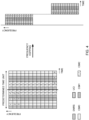
- FIG. 3 shows a configuration (frequency hopping), in which 1 slot is divided into 2 parts (first-half slot and second-half slot) and allocated to different frequency domains.
- FIG. 3 shows a case of dividing 1 slot into 2 parts, but it is equally possible to divide 1 slot into three or more parts, and allocate the divided parts (or PUSCH fields) in different time and/or frequency directions.
- FIG. 3 shows a case where DMRS is allocated in the top symbol in each divided part, the locations and the number of DMRSs are not limited to these.
- uplink data may be transmitted by configuring an uplink shared channel in different time and/or frequency domains
- studies are underway on controlling mapping of uplink data based on a predetermined order of allocation (order of mapping). For example, considering the quality and delay performance when frequency hopping is applied, data (CBs) may be mapped in the orders shown in FIG. 3 and FIG. 4 .
- FIG. 3 shows a configuration in which, in PUSCH fields of different times and/or frequencies (here, the first-half slot and the second-half slot), each CB is allocated in a same order (pattern) in the time direction (option A). Note that FIG. 3 shows a case where frequency-first mapping is applied to CBs mapped in each PUSCH field. To be more specific, in FIG. 3 , in the first-half slot and the second-half slot, CB #1, CB #2 and CB #3 are allocated in order in the time direction.
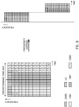
- FIG. 4 shows a configuration in which, in PUSCH fields of different times and/or frequencies (here, the first-half slot and the second-half slot), CBs are allocated in different orders in the time direction (option B). Note that FIG. 4 shows a case where frequency-first mapping is applied to CBs mapped in each PUSCH field. To be more specific, in FIG. 4 , in the first-half slot, CB #1, CB #2 and CB #3 are allocated in order in the time direction and, in the second-half slot, CB #3, CB #2 and CB #1 are allocated in order in the time direction.
- mapping patterns that can be applied to UL data are by no means limited to the configurations shown in option A and option B.
- future radio communication systems may be configured so that uplink data is transmitted by configuring PUSCH in varying time domains and/or frequency domains (for example, by applying frequency hopping to PUSCH).
- uplink data is transmitted by configuring PUSCH in varying time domains and/or frequency domains (for example, by applying frequency hopping to PUSCH).
- UCIs are multiplexed (or punctured) only in specific PUSCH fields, in a selective manner, the number of UCIs to be multiplexed (or the number of UCIs punctured) may vary between different PUSCH fields.
- Future radio communication systems are planned to be designed to control retransmission in units of TBs or in units of one or more CBs (code block groups (CBGs)). Therefore, when UL data is transmitted from UE, a base station performs error detection on a per CB basis, and transmits ACKs/NACKs in response to all CBs (TBs) or in response to every CBG (multiple CBs). Therefore, when a particular CB shows a deterioration in error rate, CBs which the base station has managed to receive properly are also retransmitted, and there is a danger that increased overhead and/or delay may pose problems.
- CBGs code block groups
- the present inventors have focused on the fact that the differences in error rates between CBs can be reduced, by making the number of UCIs multiplexed vary less among multiple PUSCH fields that differ in frequency and/or time, and come up with the idea of exerting control so that uplink control information is multiplexed in each of multiple PUSCH fields.
- the number of UCIs multiplexed the number of resources to be punctured (for example, the number of symbols and/or the number of resource elements)
- the number of UCIs multiplexed the number of resources to be punctured (for example, the number of symbols and/or the number of resource elements)
- UCI may be multiplexed in multiple PUSCH fields that differ in frequency and/or time
- the present inventors have come up with the idea of controlling UCI-multiplexing positions (puncturing positions) in each PUSCH field based on predetermined allocation patterns.
- predetermined allocation patterns are used regardless of how many CBs are used to transmit uplink data, so that the burden of transmission processes (for example, mapping process) in UE can be reduced.
- UCI may include at least one of a scheduling request (SR), delivery acknowledgment information (also referred to as “HARQ-ACK (Hybrid Automatic Repeat reQuest-ACKnowledgement),” “ACK or NACK (Negative ACK),” “A/N,” and so on) in response to a downlink data channel (for example, PDSCH (Physical Downlink Shared CHannel)), channel state information (CSI), beam index information (BI), and a buffer status report (BSR).
- SR scheduling request
- HARQ-ACK Hybrid Automatic Repeat reQuest-ACKnowledgement
- ACK or NACK Negative ACK
- A/N ACK
- UCI includes delivery acknowledgment information.
- the number of CBs to map to a predetermined time unit may be 2 or less, or 4 or more. Also, embodiments of the present invention may be applied to predetermined block units apart from CB units.
- 1 slot is comprised of 14 symbols
- the number of symbols that constitute 1 slot is not limited to 14, and 1 slot may be comprised of any other number of symbols (for example, 7 symbols).
- the following description will show cases of using intra-slot frequency hopping, the herein-contained embodiments can also be applied to inter-slot frequency hopping as well.
- the rate matching process may be applied instead of the puncturing process or together with the puncturing process.
- the burden of transmission processes for example, the mapping process
- FIG. 6 and FIG. 7 show examples of cases in which uplink control information is multiplexed on each of the PUSCHs configured in multiple domains of different times and/or frequencies.
- FIG. 6 and FIG. 7 show cases in which a PUSCH is divided into the first-half slot (the first field) and the second-half slot (the second field) and allocated to different frequencies (by applying frequency hopping).
- the number of PUSCH fields to use to transmit uplink data is not limited to 2, and may be 3 or more. Also, the number of symbols that constitute each PUSCH field may vary.
- FIG. 6 and FIG. 7 show cases where predetermined CBs are allocated in a distributed manner so that their code sequences are allocated across the first field and the second field where PUSCH is allocated, but this is by no means limiting. Also, although cases are illustrated in which a demodulation reference signal (DMRS) in allocated in every slot's top symbol, the number and/or the positions of DMRSs are by no means limited.
- DMRS demodulation reference signal
- FIG. 6 shows an example of multiplexing UCI, in a configuration in which CBs are allocated in different PUSCH fields, in a same order in the time direction (option A).
- FIG. 7 shows an example of multiplexing UCI, in a configuration in which CBs are allocated in different PUSCH fields, in different orders in the time direction (option B).
- the multiplexing (or the puncturing positions) of UCI is controlled by applying predetermined allocation patterns to every PUSCH field.
- different allocation patterns may be applied to a number of PUSCH fields (for example, the first and second fields). Applying different allocation patterns means controlling UCI to be multiplexed (or punctured) in different positions in each PUSCH field.
- UCI is multiplexed, first in the time direction, from the front in the time direction.
- UCI is multiplexed, first in the time direction, from the end in the time direction (allocation configuration #1).
- the front in the time direction refers to, for example, the top symbol in the PUSCH field
- the end in the time direction refers to, for example, the last symbol in the PUSCH field.
- UCI is multiplexed, first in the time direction, from the end in the time direction.
- UCI is multiplexed, first in the time direction, from the front in the time direction (allocation configuration #2).
- the UCI may be multiplexed either contiguously or non-contiguously along the time direction.
- a same allocation pattern may be applied to multiple PUSCH fields (for example, the first and second fields). Applying a same allocation pattern means controlling UCI to be multiplexed (or punctured) in a same location in each PUSCH field.
- UCI is multiplexed, first in the time direction, from the front in the time direction (allocation configuration #3).
- UCI is multiplexed, first in the time direction, from the end in the time direction (allocation configuration #4).
- the UCI may be multiplexed either contiguously or non-contiguously along the time direction.
- UCI may be allocated in the time direction from a symbol apart from the first or last symbol (a symbol in-between).
- UCI is first multiplexed in the frequency direction. For example, when each CB is first mapped in the time direction, the number of times to puncture each CB can be distributed by mapping UCI first in the frequency direction.
- FIG. 6 exemplifies the case of using allocation configuration #1.
- UCI is multiplexed first in the time direction, from the top symbol (the symbol to neighbor the DMRS) in the PUSCH field of the first-half slot. Furthermore, UCI is multiplexed first in the time direction, from the last symbol in the PUSCH field of the second-half slot. By this means, UCI can be distributed and multiplexed in each PUSCH field.
- FIG. 7 exemplifies the case of using allocation configuration #3.
- UCI is multiplexed first in the time direction, from the top symbol, in both the PUSCH field in the first half of a slot and the PUSCH field in the second half of the slot.
- UCI can be distributed and multiplexed in each PUSCH field.
- UCI when UCI is transmitted using PUSCH, UCI is controlled to be multiplexed in each of a number of PUSCH fields, so that the amount of puncturing can be distributed among the PUSCH fields (each CB).
- UCI is controlled to be multiplexed in each of a number of PUSCH fields, so that the amount of puncturing can be distributed among the PUSCH fields (each CB).
- predetermined allocation patterns may be applied to the UCI to be multiplexed on each PUSCH. This allows a common allocation pattern to be applied even when the number of CBs and/or the location to allocate CBs are likely to change every time UL data is transmitted (for example, per slot), so that the burden of transmission processing in UE can be reduced.
- FIG. 6 and FIG.7 have shown cases in which UCI is multiplexed in a same frequency domain, along the time direction, but the method of multiplexing UCI is not limited to this.
- the UCI to be multiplexed in individual PUSCH fields may be multiplexed on different frequency resources (see FIG. 8 ).
- FIG. 8 shows a case where UCI is multiplexed, in each PUSCH field (here, the first and second fields), in a number of resources that are different in frequency and time. Note that, in FIG. 8 , UCI is multiplexed non-contiguously in the frequency and time directions, but UCI may be multiplexed contiguously in at least one of the frequency and time directions.
- FIG. 8 shows a case in which a same allocation pattern (variation of allocation configuration #3) is applied to the first field and the second field, it is equally possible to apply varying allocation patterns. Also, although FIG. 8 shows a case in which the configuration of option A is applied to uplink data (CB) mapping, the configuration of option B is equally applicable.
- CB uplink data
- a frequency diversity effect for UCI can be gained by inserting UCI in different frequency domains in each PUSCH field (for example, by inserting UCI so as to shift along the frequency direction).
- UCI may be inserted in each of a number of PUSCH fields (for example, the first and second fields) one by one (for example, the first field ⁇ the second field ⁇ the first field ⁇ the second field, and on and on).
- a configuration may be employed here in which UCI is first inserted in a specific PUSCH field for a predetermined number of times and then inserted in the following CB (for example, the first field ⁇ the first field ⁇ the first field ⁇ the second field, and on and on).
- each PUSCH field may be defined in the specification in advance, or may be reported from a base station to a user terminal via higher layer signaling and/or downlink control information.
- FIG. 6 to FIG. 8 have shown cases in which the configurations of option A and option B are applied to the mapping of uplink data (each CB), the configurations to which the present embodiment can be applied are not limited to these.
- the methods for multiplexing UCI according to the present embodiment may be applied to configurations in which predetermined CBs (here, CBs #0 and #2) are not allocated across a number of PUSCH fields (here, the first and second fields).
- CBs to allocate to different PUSCH fields may be the same or different. Also, some CBs may be mapped so that their code sequences are distributed across multiple PUSCH fields, and the rest of the CBs may be mapped to only specific PUSCH fields.
- uplink data mapping method (the uplink data being, for example, CBs) applies to each PUSCH field (that is, which one of option A, option B and/or others is used) may be defined in the specification in advance, or may be reported from a base station to a user terminal via higher layer signaling and/or downlink control information.
- FIG. 6 to FIG. 9 have exemplified cases in which 3 CBs are transmitted, the number of CBs that can be used is not limited to 3.
- the number of CBs may be 1 or 2, or may be 4 or more. Note that, although the amount of puncturing does not vary between CBs when the number of CBs is 1, if UCI multiplexing is controlled as when the number of CBs is 2 or more, there is no need to change the method for multiplexing UCI depending on the number of CBs. In this case, the burden of transmission processes in UE can be reduced.
- FIG. 6 to FIG. 9 show cases where 2 PUSCH fields are configured by dividing 1 slot into 2 slots -- namely, the first-half slot and the second-half slotby applying frequency hopping, the number of PUSCH fields that can be used is not limited to 2.
- a PUSCH field may be divided into 3 or more parts and used.
- multiple PUSCH fields may be comprised of different numbers of symbols.
- FIG. 6 to FIG. 9 have shown cases in which frequency hopping is used (when allocating PUSCH fields in different frequency directions), the configurations of PUSCH fields that can be used are not limited to these.
- the herein-contained embodiments may be applied to configurations that do not use frequency hopping (for example, a configuration to provide multiple PUSCH fields in different time domains). Even when frequency hopping is not used, it is still possible to prevent the amount of puncturing from increasing in particular CBs by multiplexing UCI in every PUSCH field.
- different PUSCH fields may be provided only in frequency fields that are configured in a same time domain.
- radio communication system As a radio communication system according to the present embodiment, each radio communication method according to the above-described embodiments is employed. Note that the radio communication methods according to the herein-contained examples of the present invention may be applied individually, or may be combined and applied.
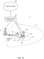
- FIG. 10 is a diagram to show an exemplary schematic structure of a radio communication system according to an embodiment of the present invention.
- a radio communication system 1 can adopt carrier aggregation (CA) and/or dual connectivity (DC) to group a plurality of fundamental frequency blocks (component carriers) into one, where the LTE system bandwidth (for example, 20 MHz) constitutes 1 unit.
- CA carrier aggregation
- DC dual connectivity
- the radio communication system 1 may be referred to as "SUPER 3G,” "LTE-A (LTE-Advanced),” “IMT-Advanced,” “4G,” “5G,” “FRA (Future Radio Access),” "NR (New RAT)” and so on.
- the radio communication system 1 shown in FIG. 10 includes a radio base station 11 that forms a macro cell C1, and radio base stations 12a to 12c that are allocated within the macro cell C1 and that form small cells C2, which are narrower than the macro cell C1. Also, user terminals 20 are allocated in the macro cell C1 and in each small cell C2. A configuration in which different numerologies are applied between cells may be adopted. Note that a "numerology" refers to a set of communication parameters that characterize the design of signals in a given RAT and/or the design of the RAT.
- the user terminals 20 can connect with both the radio base station 11 and the radio base stations 12.
- the user terminals 20 may use the macro cell C1 and the small cells C2, which use different frequencies, at the same time, by means of CA or DC.
- the user terminals 20 can execute CA or DC by using a plurality of cells (CCs) (for example, two or more CCs).
- CCs cells
- the user terminals can use license band CCs and unlicensed band CCs as a plurality of cells.
- the user terminal 20 can perform communication using time division duplexing (TDD) or frequency division duplexing (FDD) in each cell.
- TDD time division duplexing
- FDD frequency division duplexing
- a TDD cell and an FDD cell may be referred to as a "TDD carrier (frame configuration type 2)," and an “FDD carrier (frame configuration type 1),” respectively.
- each cell carrier
- either subframes having a relatively long time duration for example, 1 ms
- TTIs also referred to as "TTIs,” “normal TTIs,” “long TTIs,” “normal subframes,” “long subframes,” “slots,” and/or the like
- subframes having a relatively short time duration also referred to as “short TTIs,” “short subframes,” and/or the like
- subframes of two or more time durations may be applied.
- a carrier of a relatively low frequency band for example, 2 GHz
- a narrow bandwidth referred to as, for example, an "existing carrier," a “legacy carrier” and so on.
- a carrier of a relatively high frequency band for example, 3.5 GHz, 5 GHz, 30 to 70 GHz and so on
- a wide bandwidth may be used, or the same carrier as that used in the radio base station 11 may be used.
- the structure of the frequency band for use in each radio base station is by no means limited to these.
- a structure may be employed here in which wire connection (for example, means in compliance with the CPRI (Common Public Radio Interface) such as optical fiber, the X2 interface and so on) or wireless connection is established between the radio base station 11 and the radio base station 12 (or between 2 radio base stations 12).
- wire connection for example, means in compliance with the CPRI (Common Public Radio Interface) such as optical fiber, the X2 interface and so on
- wireless connection is established between the radio base station 11 and the radio base station 12 (or between 2 radio base stations 12).
- the radio base station 11 and the radio base stations 12 are each connected with higher station apparatus 30, and are connected with a core network 40 via the higher station apparatus 30.
- the higher station apparatus 30 may be, for example, access gateway apparatus, a radio network controller (RNC), a mobility management entity (MME) and so on, but is by no means limited to these.
- RNC radio network controller
- MME mobility management entity
- each radio base station 12 may be connected with the higher station apparatus 30 via the radio base station 11.
- the radio base station 11 is a radio base station having a relatively wide coverage, and may be referred to as a "macro base station,” a “central node,” an “eNB (eNodeB),” a “transmission/reception point” and so on.
- the radio base stations 12 are radio base stations having local coverages, and may be referred to as “small base stations,” “micro base stations,” “pico base stations,” “femto base stations,” “HeNBs (Home eNodeBs),” “RRHs (Remote Radio Heads),” “transmission/reception points” and so on.
- the radio base stations 11 and 12 will be collectively referred to as “radio base stations 10,” unless specified otherwise.
- the user terminals 20 are terminals to support various communication schemes such as LTE, LTE-A and so on, and may be either mobile communication terminals or stationary communication terminals. Furthermore, the user terminals 20 can perform inter-terminal (D2D) communication with other user terminals 20.
- D2D inter-terminal
- OFDMA orthogonal Frequency Division Multiple Access
- SC-FDMA Single-Carrier Frequency Division Multiple Access
- OFDMA is a multi-carrier communication scheme to perform communication by dividing a frequency bandwidth into a plurality of narrow frequency bandwidths (subcarriers) and mapping data to each subcarrier.
- SC-FDMA is a single-carrier communication scheme to mitigate interference between terminals by dividing the system bandwidth into bands formed with one or continuous resource blocks per terminal, and allowing a plurality of terminals to use mutually different bands.
- the uplink and downlink radio access schemes are not limited to the combinations of these, and OFDMA may be used in UL.
- SC-FDMA can also be applied a side link (SL) that is used in inter-terminal communication.
- SL side link
- DL channels that are used in radio communication system 1 include DL data channel that is shared by each user terminal 20 (also referred to as “PDSCH (Physical Downlink Shared CHannel),” “DL shared channel” and so forth), a broadcast channel (PBCH (Physical Broadcast CHannel)), L1/L2 control channels and so on. At least one of user data, higher layer control information and SIBs (System Information Blocks) is communicated in the PDSCH. Also, the MIB (Master Information Block) is communicated in the PBCH.
- PDSCH Physical Downlink Shared CHannel
- PBCH Physical Broadcast CHannel
- SIBs System Information Blocks
- MIB Master Information Block
- the L1/L2 control channels include DL control channels (PDCCH (Physical Downlink Control CHannel), EPDCCH (Enhanced Physical Downlink Control CHannel) and so on), PCFICH (Physical Control Format Indicator CHannel), PHICH (Physical Hybrid-ARQ Indicator CHannel) and so on.
- Downlink control information DCI
- DCI Downlink control information
- the number of OFDM symbols to use for the PDCCH is communicated by the PCFICH.
- the EPDCCH is frequency-division-multiplexed with the PDSCH and used to communicate DCI and so on, like the PDCCH.
- PUSCH delivery acknowledgment information (A/N, HARQ-ACK, etc.) can be communicated in at least one of the PHICH, the PDCCH and the EPDCCH.
- UL channels that are used in the radio communication system 1 include UL data channel that is shared by each user terminal 20 (also referred to as “PUSCH (Physical Uplink Shared CHannel),” “UL shared channel” and/or the like), a UL control channel (PUCCH (Physical Uplink Control CHannel)), a random access channel (PRACH (Physical Random Access CHannel)) and so on.
- PUSCH Physical Uplink Shared CHannel
- PUCCH Physical Uplink Control CHannel
- PRACH Physical Random Access CHannel
- User data, higher layer control information and so on are communicated by the PUSCH.
- PRACH random access preambles for establishing connections with cells are communicated.
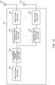
- FIG. 11 is a diagram to show an exemplary overall structure of a radio base station according to the present embodiment.
- a radio base station 10 has a plurality of transmitting/receiving antennas 101, amplifying sections 102, transmitting/receiving sections 103, a baseband signal processing section 104, a call processing section 105 and a communication path interface 106. Note that one or more transmitting/receiving antennas 101, amplifying sections 102 and transmitting/receiving sections 103 may be provided.
- User data to be transmitted from the radio base station 10 to a user terminal 20 on the downlink is input from the higher station apparatus 30 to the baseband signal processing section 104, via the communication path interface 106.
- the user data is subjected to transmission processes, including, for example, at least one of a PDCP (Packet Data Convergence Protocol) layer process, division and coupling of the user data, RLC (Radio Link Control) layer transmission processes such as RLC retransmission control, MAC (Medium Access Control) retransmission control (for example, an HARQ (Hybrid Automatic Repeat reQuest) process), scheduling, transport format selection, channel coding, rate matching, scrambling, an inverse fast Fourier transform (IFFT) process and a precoding process, and the result is forwarded to the transmitting/receiving sections 103.
- PDCP Packet Data Convergence Protocol
- RLC Radio Link Control
- MAC Medium Access Control
- HARQ Hybrid Automatic Repeat reQuest
- IFFT inverse fast Fourier transform
- precoding forwarded to each transmitting/receiving section 103.
- downlink control signals are also subjected to transmission processes such as channel coding and/or an
- Baseband signals that are precoded and output from the baseband signal processing section 104 on a per antenna basis are converted into a radio frequency band in the transmitting/receiving sections 103, and then transmitted.
- the radio frequency signals having been subjected to frequency conversion in the transmitting/receiving sections 103 are amplified in the amplifying sections 102, and transmitted from the transmitting/receiving antennas 101.
- the transmitting/receiving sections 103 can be constituted by transmitters/receivers, transmitting/receiving circuits or transmitting/receiving apparatus that can be described based on general understanding of the technical field to which the present invention pertains. Note that a transmitting/receiving section 103 may be structured as a transmitting/receiving section in one entity, or may be constituted by a transmitting section and a receiving section.
- radio frequency signals that are received in the transmitting/receiving antennas 101 are each amplified in the amplifying sections 102.
- the transmitting/receiving sections 103 receive the UL signals amplified in the amplifying sections 102.
- the received signals are converted into the baseband signal through frequency conversion in the transmitting/receiving sections 103 and output to the baseband signal processing section 104.
- UL data that is included in the UL signals that are input is subjected to a fast Fourier transform (FFT) process, an inverse discrete Fourier transform (IDFT) process, error correction decoding, a MAC retransmission control receiving process, and RLC layer and PDCP layer receiving processes, and forwarded to the higher station apparatus 30 via the communication path interface 106.
- the call processing section 105 performs, for example, at least one of call processing such as setting up and releasing of communication channels, management of the state of the radio base station 10 and management of radio resources.
- the communication path interface section 106 transmits and receives signals to and from the higher station apparatus 30 via a predetermined interface. Also, the communication path interface 106 may transmit and/or receive signals (backhaul signaling) with neighboring radio base stations 10 via an inter-base station interface (for example, an interface in compliance with the CPRI (Common Public Radio Interface), such as optical fiber, the X2 interface, etc.).
- an inter-base station interface for example, an interface in compliance with the CPRI (Common Public Radio Interface), such as optical fiber, the X2 interface, etc.).
- the transmitting/receiving sections 103 receive uplink data in units of predetermined blocks by using uplink shared channels configured in multiple domains that are different in frequency and/or time. Also, when uplink control information is transmitted from UE by using an uplink shared channel configured in multiple domains, the transmitting/receiving sections 103 receive the uplink control information that is multiplexed in each of the multiple domains. Also, the transmitting/receiving sections 103 may transmit information about the mapping configurations that UE applies to uplink data, and/or information about the allocation configurations that are applied to UCI multiplexing, by using higher layer signaling and/or downlink control information.
- FIG. 12 is a diagram to show an exemplary functional structure of a radio base station according to the present embodiment. Note that, although FIG. 12 primarily shows functional blocks that pertain to characteristic parts of the present embodiment, the radio base station 10 has other functional blocks that are necessary for radio communication as well. As shown in FIG. 12 , the baseband signal processing section 104 has a control section 301, a transmission signal generation section 302, a mapping section 303, a received signal processing section 304 and a measurement section 305.
- the control section 301 controls the whole of the radio base station 10.
- the control section 301 controls, for example, at least one of generation of downlink signals in the transmission signal generation section 302, mapping of downlink signals in the mapping section 303, the receiving process (for example, demodulation) of uplink signals in the received signal processing section 304, and measurements in the measurement section 305.
- control section 301 schedules user terminals 20. For example, the control section 301 controls the transmission timing and/or the transmission period of an uplink shared channel, and the transmission timing and/or the transmission period of uplink control information. In addition, the control section 301 controls receipt of the uplink shared channel on which uplink data and uplink control information are multiplexed.
- the control section 301 can be constituted by a controller, a control circuit or control apparatus that can be described based on general understanding of the technical field to which the present invention pertains.
- the transmission signal generation section 302 generates DL signals (including DL data signals, DL control signals, DL reference signals and so on) based on commands from the control section 301, and outputs these signals to the mapping section 303.
- a signal generator, a signal generation circuit or signal generation apparatus that can be described based on general understanding of the technical field to which the present invention pertains can be used.
- the mapping section 303 maps the DL signals generated in the transmission signal generation section 302 to predetermined radio resources based on commands from the control section 301, and outputs these to the transmitting/receiving sections 103.
- a mapper, a mapping circuit or mapping apparatus that can be described based on general understanding of the technical field to which the present invention pertains can be used.
- the received signal processing section 304 performs receiving processes (for example, demapping, demodulation, decoding, etc.) of UL signals transmitted from the user terminals 20 (including, for example, a UL data signal, a UL control signal, a UL reference signal, etc.). To be more specific, the received signal processing section 304 may output the received signals and/or the signals after receiving processes to the measurement section 305.
- receiving processes for example, demapping, demodulation, decoding, etc.
- the measurement section 305 conducts measurements with respect to the received signals.
- the measurement section 305 can be constituted by a measurer, a measurement circuit or measurement apparatus that can be described based on general understanding of the technical field to which the present invention pertains.
- the measurement section 305 may measure the channel quality in UL based on, for example, the received power (for example, RSRP (Reference Signal Received Power)) and/or the received quality (for example, RSRQ (Reference Signal Received Quality)) of UL reference signals.
- the measurement results may be output to the control section 301.
- FIG. 13 is a diagram to show an exemplary overall structure of a user terminal according to the present embodiment.
- a user terminal 20 has a plurality of transmitting/receiving antennas 201 for MIMO communication, amplifying sections 202, transmitting/receiving sections 203, a baseband signal processing section 204 and an application section 205.
- Radio frequency signals that are received in a plurality of transmitting/receiving antennas 201 are each amplified in the amplifying sections 202.
- the transmitting/receiving sections 203 receive the DL signals amplified in the amplifying sections 202.
- the received signals are subjected to frequency conversion and converted into the baseband signal in the transmitting/receiving sections 203, and output to the baseband signal processing section 204.
- the baseband signal processing section 204 performs receiving processes for the baseband signal that is input, including at least one of an FFT process, error correction decoding, a retransmission control receiving process and so on.
- the DL data is forwarded to the application section 205.
- the application section 205 performs processes related to higher layers above the physical layer and the MAC layer, and so on.
- UL data is input from the application section 205 to the baseband signal processing section 204.
- the baseband signal processing section 204 performs at least one of a retransmission control process (for example, an HARQ process), channel coding, rate matching, puncturing, a discrete Fourier transform (DFT) process, an IFFT process and so on, and the result is forwarded to each transmitting/receiving section 203.
- a retransmission control process for example, an HARQ process
- DFT discrete Fourier transform
- IFFT IFFT process
- UCI (including, for example, at least one of an A/N in response to a DL signal, channel state information (CSI) and a scheduling request (SR), and/or others) is also subjected to at least one of channel coding, rate matching, puncturing, a DFT process, an IFFT process and so on, and the result is forwarded to the transmitting/receiving sections 203.
- CSI channel state information
- SR scheduling request
- Baseband signals that are output from the baseband signal processing section 204 are converted into a radio frequency band in the transmitting/receiving sections 203 and transmitted.
- the radio frequency signals that are subjected to frequency conversion in the transmitting/receiving sections 203 are amplified in the amplifying sections 202, and transmitted from the transmitting/receiving antennas 201.
- the transmitting/receiving sections 203 transmit uplink data in units of predetermined blocks by using uplink shared channels configured in multiple domains that are different in frequency and/or time. Also, when transmitting uplink control information by using an uplink shared channel that is configured in multiple domains, the transmitting/receiving sections 203 multiplex and transmit uplink control information in a number of domains. Also, the transmitting/receiving sections 203 may receive information about the mapping configurations that UE applies to uplink data, and/or information about the allocation configurations that are applied to UCI multiplexing, by using higher layer signaling and/or downlink control information.
- a transmitting/receiving section 203 may be structured as 1 transmitting/receiving section, or may be formed with a transmitting section and a receiving section.
- FIG. 14 is a diagram to show an exemplary functional structure of a user terminal according to the present embodiment. Note that, although FIG. 14 primarily shows functional blocks that pertain to characteristic parts of the present embodiment, the user terminal 20 has other functional blocks that are necessary for radio communication as well. As shown in FIG. 14 , the baseband signal processing section 204 provided in the user terminal 20 has a control section 401, a transmission signal generation section 402, a mapping section 403, a received signal processing section 404 and a measurement section 405.
- the control section 401 controls the whole of the user terminal 20.
- the control section 401 controls, for example, at least one of generation of UL signals in the transmission signal generation section 402, mapping of UL signals in the mapping section 403, the receiving process of DL signals in the received signal processing section 404 and measurements in the measurement section 405.
- the control section 401 also controls the transmission of uplink data (for example, CBs) and uplink control information (UCI) using an uplink shared channel (PUSCH). For example, when uplink control information is transmitted using an uplink shared channel, the control section 401 controls so that uplink control information is multiplexed in each of a number of PUSCH fields.
- uplink data for example, CBs
- UCI uplink control information
- PUSCH uplink shared channel
- control section 401 may control the multiplexing of uplink control information in multiple PUSCH fields based on a same allocation pattern. Also, the control section 401 may control the multiplexing of uplink control information in multiple PUSCH fields based on different allocation patterns.
- control section 401 may control the multiplexing of uplink control information based on a common allocation pattern regardless of how many predetermined blocks of uplink data are allocated to multiple PUSCH fields. Also, the control section 401 may allocate uplink data that corresponds to a same predetermined block, in each of a number of domains.
- the control section 401 can be constituted by a controller, a control circuit or control apparatus that can be described based on general understanding of the technical field to which the present invention pertains.
- UL signals including UL data signals, UL control signals, UL reference signals, UCI, etc.
- UL reference signals including, for example, encoding, rate matching, puncturing, modulation, etc.
- a signal generator, a signal generation circuit or signal generation apparatus that can be described based on general understanding of the technical field to which the present invention pertains can be used.
- the mapping section 403 maps the uplink signals (uplink data, uplink control information, etc.) generated in the transmission signal generation section 402, to radio resources, based on commands from the control section 401, and output the result to the transmitting/receiving sections 203.
- a mapper a mapping circuit or mapping apparatus that can be described based on general understanding of the technical field to which the present invention pertains can be used.
- the received signal processing section 404 performs receiving processes (for example, demapping, demodulation, decoding, etc.) of DL signals (including DL data signals, scheduling information, DL control signals, DL reference signals, etc.).
- the received signal processing section 404 outputs the information received from the radio base station 10, to the control section 401.
- the received signal processing section 404 outputs, for example, broadcast information, system information, high layer control information related to higher layer signaling such as RRC signaling, physical layer control information (L1/L2 control information) and so on, to the control section 401.
- the received signal processing section 404 can be constituted by a signal processor, a signal processing circuit or signal processing apparatus that can be described based on general understanding of the technical field to which the present invention pertains. Also, the received signal processing section 404 can constitute the receiving section according to the present invention.
- the measurement section 405 measures channel states based on reference signals (for example, CSI-RS) from the radio base station 10, and outputs the measurement results to the control section 401. Note that the channel state measurements may be conducted per CC.
- reference signals for example, CSI-RS
- the measurement section 405 can be constituted by a signal processor, a signal processing circuit or signal processing apparatus, and a measurer, a measurement circuit or measurement apparatus that can be described based on general understanding of the technical field to which the present invention pertains.
- each functional block may be realized by one piece of apparatus that is physically and/or logically aggregated, or may be realized by directly and/or indirectly connecting two or more physically and/or logically separate pieces of apparatus (via wire or wireless, for example) and using these multiple pieces of apparatus.
- a radio base station, a user terminal and so on may function as a computer that executes the processes of the radio communication method of the present invention.
- FIG. 15 is a diagram to show an exemplary hardware structure of a radio base station and a user terminal according to the present embodiment.
- the above-described radio base stations 10 and user terminals 20 may be formed as a computer apparatus that includes a processor 1001, a memory 1002, a storage 1003, communication apparatus 1004, input apparatus 1005, output apparatus 1006 and a bus 1007.
- the word “apparatus” may be reallocated by “circuit,” “device,” “unit” and so on.
- the hardware structure of a radio base station 10 and a user terminal 20 may be designed to include one or more of each apparatus shown in the drawings, or may be designed not to include part of the apparatus.
- processor 1001 may be implemented with 1 processor, or processes may be implemented in sequence, or in different manners, on one or more processors.
- processor 1001 may be implemented with one or more chips.
- Each function of the radio base station 10 and the user terminal 20 is implemented by reading predetermined software (program) on hardware such as the processor 1001 and the memory 1002, and by controlling the calculations in the processor 1001, the communication in the communication apparatus 1004, and the reading and/or writing of data in the memory 1002 and the storage 1003.
- predetermined software program
- the processor 1001 may control the whole computer by, for example, running an operating system.
- the processor 1001 may be configured with a central processing unit (CPU), which includes interfaces with peripheral apparatus, control apparatus, computing apparatus, a register and so on.
- CPU central processing unit
- the above-described baseband signal processing section 104 (204), call processing section 105 and so on may be implemented by the processor 1001.
- the processor 1001 reads programs (program codes), software modules, data and so forth from the storage 1003 and/or the communication apparatus 1004, into the memory 1002, and executes various processes according to these.
- programs programs to allow computers to execute at least part of the operations of the above-described embodiments may be used.
- the control section 401 of the user terminals 20 may be implemented by control programs that are stored in the memory 1002 and that operate on the processor 1001, and other functional blocks may be implemented likewise.
- the memory 1002 is a computer-readable recording medium, and may be constituted by, for example, at least one of a ROM (Read Only Memory), an EPROM (Erasable Programmable ROM), an EEPROM (Electrically EPROM), a RAM (Random Access Memory) and/or other appropriate storage media.
- the memory 1002 may be referred to as a "register,” a "cache,” a “main memory (primary storage apparatus)” and so on.
- the memory 1002 can store executable programs (program codes), software modules and the like for implementing the radio communication methods according to the present embodiment.
- the storage 1003 is a computer-readable recording medium, and may be constituted by, for example, at least one of a flexible disk, a floppy (registered trademark) disk, a magneto-optical disk (for example, a compact disc (CD-ROM (Compact Disc ROM) and so on), a digital versatile disc, a Blu-ray (registered trademark) disk), a removable disk, a hard disk drive, a smart card, a flash memory device (for example, a card, a stick, a key drive, etc.), a magnetic stripe, a database, a server, and/or other appropriate storage media.
- the storage 1003 may be referred to as "secondary storage apparatus.”
- the communication apparatus 1004 is hardware (transmitting/receiving device) for allowing inter-computer communication by using wired and/or wireless networks, and may be referred to as, for example, a "network device,” a “network controller,” a “network card,” a “communication module” and so on.
- the communication apparatus 1004 may be configured to include a high frequency switch, a duplexer, a filter, a frequency synthesizer and so on in order to realize, for example, frequency division duplex (FDD) and/or time division duplex (TDD).
- FDD frequency division duplex
- TDD time division duplex
- the above-described transmitting/receiving antennas 101 (201), amplifying sections 102 (202), transmitting/receiving sections 103 (203), communication path interface 106 and so on may be implemented by the communication apparatus 1004.
- the input apparatus 1005 is an input device for receiving input from the outside (for example, a keyboard, a mouse, a microphone, a switch, a button, a sensor and so on).
- the output apparatus 1006 is an output device for allowing sending output to the outside (for example, a display, a speaker, an LED (Light Emitting Diode) lamp and so on). Note that the input apparatus 1005 and the output apparatus 1006 may be provided in an integrated structure (for example, a touch panel).
- bus 1007 so as to communicate information.
- the bus 1007 may be formed with a single bus, or may be formed with buses that vary between pieces of apparatus.
- the radio base station 10 and the user terminal 20 may be structured to include hardware such as a microprocessor, a digital signal processor (DSP), an ASIC (Application-Specific Integrated Circuit), a PLD (Programmable Logic Device), an FPGA (Field Programmable Gate Array) and so on, and part or all of the functional blocks may be implemented by the hardware.
- the processor 1001 may be implemented with at least one of these pieces of hardware.
- channels and/or “symbols” may be reallocated by “signals” (or “signaling”).
- signals may be “messages.”
- a reference signal may be abbreviated as an "RS,” and may be referred to as a “pilot,” a “pilot signal” and so on, depending on which standard applies.
- a “component carrier (CC)” may be referred to as a "cell,” a “frequency carrier,” a “carrier frequency” and so on.
- a radio frame may be comprised of one or more periods (frames) in the time domain.
- Each of one or more periods (frames) constituting a radio frame may be referred to as a "subframe.”
- a subframe may be comprised of one or multiple slots in the time domain.
- a subframe may be a fixed time duration (for example, 1 ms) not dependent on the numerology.
- a slot may be comprised of one or more symbols in the time domain (OFDM (Orthogonal Frequency Division Multiplexing) symbols, SC-FDMA (Single Carrier Frequency Division Multiple Access) symbols, and so on).
- a slot may be a time unit based on numerology.
- a slot may include a plurality of minislots. Each minislot may be comprised of one or more symbols in the time domain. Also, a minislot may be referred to as a "subslot.”
- a radio frame, a subframe, a slot, a minislot and a symbol all represent the time unit in signal communication.
- a radio frame, a subframe, a slot, a minislot and a symbol may be each called by other applicable names.
- 1 subframe may be referred to as a "transmission time interval (TTI)," or a plurality of consecutive subframes may be referred to as a "TTI,” or 1 slot or minislot may be referred to as a "TTI.”
- TTI transmission time interval
- a subframe and/or a TTI may be a subframe (1 ms) in existing LTE, may be a shorter period than 1 ms (for example, 1 to 13 symbols), or may be a longer period of time than 1 ms.
- the unit to represent the TTI may be referred to as a "slot,” a "mini slot” and so on, instead of a "subframe.”
- a TTI refers to the minimum time unit of scheduling in radio communication, for example.
- a radio base station schedules the radio resources (such as the frequency bandwidth and transmission power that can be used in each user terminal) to allocate to each user terminal in TTI units.
- the definition of TTIs is not limited to this.
- the TTI may be the transmission time unit of channel-encoded data packets (transport blocks), code blocks and/or codewords, or may be the unit of processing in scheduling, link adaptation and so on. Note that, when a TTI is given, the period of time (for example, the number of symbols) in which transport blocks, code blocks and/or codewords are actually mapped may be shorter than the TTI.
- TTI 1 slot or 1 minislot
- one or more TTIs may be the minimum time unit of scheduling.
- the number of slots (the number of minislots) to constitute this minimum time unit of scheduling may be controlled.
- a TTI having a time duration of 1 ms may be referred to as a "normal TTI (TTI in LTE Rel. 8 to 12),” a “long TTI,” a “normal subframe,” a “long subframe,” and so on.
- a TTI that is shorter than a normal TTI may be referred to as a "shortened TTI,” a “short TTI,” a “partial TTI (or a “fractional TTI”),” a "shortened subframe,” a “short subframe,” a “minislot,” “a sub-slot” and so on.
- a long TTI for example, a normal TTI, a subframe, etc.
- a short TTI for example, a shortened TTI
- a TTI duration less than the TTI duration of a long TTI and not less than 1 ms.
- a resource block is the unit of resource allocation in the time domain and the frequency domain, and may include one or a plurality of consecutive subcarriers in the frequency domain. Also, an RB may include one or more symbols in the time domain, and may be 1 slot, 1 minislot, 1 subframe or 1 TTI in length. 1 TTI and 1 subframe each may be comprised of one or more resource blocks. Note that one or more RBs may be referred to as a "physical resource block (PRB (Physical RB)),” a “subcarrier group (SCG),” a “resource element group (REG),” a "PRB pair,” an “RB pair” and so on.
- PRB Physical resource block
- SCG subcarrier group
- REG resource element group
- a resource block may be comprised of one or more resource elements (REs).
- REs resource elements
- 1 RE may be a radio resource field of 1 subcarrier and 1 symbol.
- radio frames, subframes, slots, minislots, symbols and so on described above are merely examples.
- configurations pertaining to the number of subframes included in a radio frame, the number of slots per subframe or radio frame, the number of minislots included in a slot, the number of symbols and RBs included in a slot or a minislot, the number of subcarriers included in an RB, the number of symbols in a TTI, the symbol duration, the length of cyclic prefixes (CPs) and so on can be variously changed.
- a radio resource may be specified by a predetermined index.
- information, signals and so on can be output from higher layers to lower layers and/or from lower layers to higher layers.
- Information, signals and so on may be input and/or output via a plurality of network nodes.
- the information, signals and so on that are input and/or output may be stored in a specific location (for example, in a memory), or may be managed in a control table.
- the information, signals and so on to be input and/or output can be overwritten, updated or appended.
- the information, signals and so on that are output may be deleted.
- the information, signals and so on that are input may be transmitted to other pieces of apparatus.
- reporting of information is by no means limited to the aspects/embodiments described in this specification, and other methods may be used as well.
- reporting of information may be implemented by using physical layer signaling (for example, downlink control information (DCI), uplink control information (UCI), higher layer signaling (for example, RRC (Radio Resource Control) signaling, broadcast information (the master information block (MIB), system information blocks (SIBs) and so on), MAC (Medium Access Control) signaling and so on), and other signals and/or combinations of these.
- DCI downlink control information
- UCI uplink control information
- higher layer signaling for example, RRC (Radio Resource Control) signaling
- broadcast information the master information block (MIB), system information blocks (SIBs) and so on
- MAC Medium Access Control
- L1/L2 Layer 1/Layer 2 control signals
- L1 control information L1 control signal
- RRC signaling may be referred to as “RRC messages,” and can be, for example, an RRC connection setup message, RRC connection reconfiguration message, and so on.
- MAC signaling may be reported using, for example, MAC control elements (MAC CEs (Control Elements)).
- reporting of predetermined information does not necessarily have to be sent explicitly, and can be sent implicitly (for example, by not reporting this piece of information, by reporting another piece of information, and so on).
- Decisions may be made in values represented by 1 bit (0 or 1), may be made in Boolean values that represent true or false, or may be made by comparing numerical values (for example, comparison against a predetermined value).
- Software whether referred to as “software,” “firmware,” “middleware,” “microcode” or “hardware description language,” or called by other names, should be interpreted broadly, to mean instructions, instruction sets, code, code segments, program codes, programs, subprograms, software modules, applications, software applications, software packages, routines, subroutines, objects, executable files, execution threads, procedures, functions and so on.
- software, commands, information and so on may be transmitted and received via communication media.
- communication media For example, when software is transmitted from a website, a server or other remote sources by using wired technologies (coaxial cables, optical fiber cables, twisted-pair cables, digital subscriber lines (DSL) and so on) and/or wireless technologies (infrared radiation, microwaves and so on), these wired technologies and/or wireless technologies are also included in the definition of communication media.
- wired technologies coaxial cables, optical fiber cables, twisted-pair cables, digital subscriber lines (DSL) and so on
- wireless technologies infrared radiation, microwaves and so on
- system and "network” as used herein are used interchangeably.
- base station As used herein, the terms “base station (BS),” “radio base station,” “eNB,” “gNB,” “cell,” “sector,” “cell group,” “carrier,” and “component carrier” may be used interchangeably.
- a base station may be referred to as a “fixed station,” “NodeB,” “eNodeB (eNB),” “access point,” “transmission point,” “receiving point,” “femto cell,” “small cell” and so on.
- a base station can accommodate one or more (for example, 3) cells (also referred to as "sectors"). When a base station accommodates a plurality of cells, the entire coverage area of the base station can be partitioned into multiple smaller areas, and each smaller area can provide communication services through base station subsystems (for example, indoor small base stations (RRHs (Remote Radio Heads))).
- RRHs Remote Radio Heads
- the term "cell” or “sector” refers to part or all of the coverage area of a base station and/or a base station subsystem that provides communication services within this coverage.
- MS mobile station
- UE user equipment
- terminal terminal
- a base station may be referred to as a "fixed station,” “NodeB,” “eNodeB (eNB),” "access point,” “transmission point,” “receiving point,” “femto cell,” “small cell” and so on.
- a mobile station may be referred to, by a person skilled in the art, as a "subscriber station,” “mobile unit,” “subscriber unit,” “wireless unit,” “remote unit,” “mobile device,” “wireless device,” “wireless communication device,” “remote device,” “mobile subscriber station,” “access terminal,” “mobile terminal,” “wireless terminal,” “remote terminal,” “handset,” “user agent,” “mobile client,” “client” or some other suitable terms.
- radio base stations in this specification may be interpreted as user terminals.
- each aspect/embodiment of the present invention may be applied to a configuration in which communication between a radio base station and a user terminal is reallocated with communication among a plurality of user terminals (D2D (Device-to-Device)).
- user terminals 20 may have the functions of the radio base stations 10 described above.
- terms such as "uplink” and “downlink” may be interpreted as "side.”
- an uplink channel may be interpreted as a side channel.
- the user terminals in this specification may be interpreted as radio base stations.
- the radio base stations 10 may have the functions of the user terminals 20 described above.
- base stations may, in some cases, be performed by their upper nodes.
- various operations that are performed so as to communicate with terminals can be performed by base stations, one or more network nodes (for example, MMEs (Mobility Management Entities), S-GWs (Serving-Gateways) and so on may be possible, but these are not limiting) other than base stations, or combinations of these.
- MMEs Mobility Management Entities
- S-GWs Serving-Gateways
- LTE Long Term Evolution
- LTE-A Long Term Evolution
- LTE-B Long Term Evolution-Beyond
- SUPER 3G IMT-Advanced
- 4G 4th generation mobile communication system
- 5G 5th generation mobile communication system
- FRA Fluture Radio Access
- New-RAT Radio Access Technology
- NR New Radio
- NX New radio access
- FX Fluture generation radio access
- GSM registered trademark
- CDMA 2000 UMB (Ultra Mobile Broadband)
- IEEE 802.11 Wi-Fi (registered trademark)
- IEEE 802.16 WiMAX (registered trademark)
- IEEE 802.20 UWB (Ultra-WideBand
- Bluetooth registered trademark
- references to elements with designations such as “first,” “second” and so on as used herein does not generally limit the number/quantity or order of these elements. These designations are used herein only for convenience, as a method for distinguishing between two or more elements. In this way, reference to the first and second elements does not imply that only 2 elements may be employed, or that the first element must precede the second element in some way.
- judge and “determine” as used herein may encompass a wide variety of actions. For example, to “judge” and “determine” as used herein may be interpreted to mean making judgements and determinations related to calculating, computing, processing, deriving, investigating, looking up (for example, searching a table, a database or some other data structure), ascertaining and so on. Furthermore, to “judge” and “determine” as used herein may be interpreted to mean making judgements and determinations related to receiving (for example, receiving information), transmitting (for example, transmitting information), inputting, outputting, accessing (for example, accessing data in a memory) and so on.
- connection means all direct or indirect connections or coupling between two or more elements, and may include the presence of one or more intermediate elements between 2 elements that are “connected” or “coupled” to each other.
- the coupling or connection between the elements may be physical, logical or a combination of these. For example, “connection” may be interpreted as "access.”
- these elements when 2 elements are connected, these elements may be considered “connected” or “coupled” to each other by using one or more electrical wires, cables and/or printed electrical connections, and, as a number of non-limiting and non-inclusive examples, by using electromagnetic energy, such as electromagnetic energy having wavelengths in the radio frequency, microwave and optical (both visible and invisible) regions.
- electromagnetic energy such as electromagnetic energy having wavelengths in the radio frequency, microwave and optical (both visible and invisible) regions.
Landscapes
- Engineering & Computer Science (AREA)
- Signal Processing (AREA)
- Computer Networks & Wireless Communication (AREA)
- Quality & Reliability (AREA)
- Mobile Radio Communication Systems (AREA)
Applications Claiming Priority (1)
| Application Number | Priority Date | Filing Date | Title |
|---|---|---|---|
| PCT/JP2017/033592 WO2019053902A1 (ja) | 2017-09-15 | 2017-09-15 | ユーザ端末及び無線通信方法 |
Publications (3)
| Publication Number | Publication Date |
|---|---|
| EP3684117A1 EP3684117A1 (en) | 2020-07-22 |
| EP3684117A4 EP3684117A4 (en) | 2021-04-07 |
| EP3684117B1 true EP3684117B1 (en) | 2023-09-06 |
Family
ID=65722524
Family Applications (1)
| Application Number | Title | Priority Date | Filing Date |
|---|---|---|---|
| EP17924978.4A Active EP3684117B1 (en) | 2017-09-15 | 2017-09-15 | User terminal and radio communication method |
Country Status (8)
| Country | Link |
|---|---|
| US (1) | US11552752B2 (pt) |
| EP (1) | EP3684117B1 (pt) |
| JP (1) | JP7116070B2 (pt) |
| CN (1) | CN111247848B (pt) |
| BR (1) | BR112020004987A2 (pt) |
| ES (1) | ES2959283T3 (pt) |
| PT (1) | PT3684117T (pt) |
| WO (1) | WO2019053902A1 (pt) |
Families Citing this family (1)
| Publication number | Priority date | Publication date | Assignee | Title |
|---|---|---|---|---|
| US11316616B2 (en) * | 2020-02-21 | 2022-04-26 | Qualcomm Incorporated | Constraint-based code block interleaver for data aided receivers |
Family Cites Families (18)
| Publication number | Priority date | Publication date | Assignee | Title |
|---|---|---|---|---|
| CN103024904A (zh) * | 2011-09-20 | 2013-04-03 | 北京三星通信技术研究有限公司 | 一种无线通信系统中的上行数据传输方法 |
| EP2761780A1 (en) * | 2011-09-30 | 2014-08-06 | Interdigital Patent Holdings, Inc. | Multipoint transmission in wireless communication |
| TWI695604B (zh) * | 2012-01-24 | 2020-06-01 | 美商內數位專利控股公司 | 無線傳輸/接收單元、在無線傳輸/接收單元中實施的方法以及網路節點 |
| US11057921B2 (en) * | 2014-10-01 | 2021-07-06 | Samsung Electronics Co., Ltd. | System and method for improving spectral efficiency and coverage for user equipments |
| WO2016072257A1 (ja) * | 2014-11-06 | 2016-05-12 | 株式会社Nttドコモ | ユーザ端末、無線基地局及び無線通信方法 |
| EP4236545A3 (en) | 2015-07-30 | 2023-09-13 | Apple Inc. | Ofdma-based multiplexing of uplink control information |
| WO2017023146A1 (en) * | 2015-08-06 | 2017-02-09 | Innovative Technology Lab Co., Ltd. | Apparatus and method for transmitting uplink control information through a physical uplink control channel |
| WO2017126940A1 (en) * | 2016-01-21 | 2017-07-27 | Samsung Electronics Co., Ltd. | Method and apparatus for transmitting uplink control information in carrier aggregation system |
| WO2017135345A1 (ja) * | 2016-02-04 | 2017-08-10 | 株式会社Nttドコモ | ユーザ端末、無線基地局及び無線通信方法 |
| US10673579B2 (en) * | 2016-03-03 | 2020-06-02 | Lg Electronics Inc. | Method and apparatus for transreceiving wireless signal in wireless communication system based on downlink scheduling information including different time unit types |
| EP4021120A1 (en) * | 2016-03-30 | 2022-06-29 | InterDigital Patent Holdings, Inc. | Reducing latency in physical channels in an lte network |
| US10243929B2 (en) * | 2016-03-30 | 2019-03-26 | Qualcomm Incorporated | Uplink control channel scheduling for jamming resilience |
| WO2018030856A1 (ko) * | 2016-08-11 | 2018-02-15 | 엘지전자 주식회사 | 무선 통신 시스템에서 단말에 의해 수행되는 상향링크 제어 정보 전송 방법 및 상기 방법을 이용하는 단말 |
| KR102462083B1 (ko) * | 2017-02-05 | 2022-11-02 | 엘지전자 주식회사 | 무선 통신 시스템에서 단말의 상향링크 제어 정보 전송 방법 및 이를 지원하는 장치 |
| WO2018204610A2 (en) * | 2017-05-04 | 2018-11-08 | Intel IP Corporation | New radio (nr) physical uplink structures and schemes |
| US10931484B2 (en) * | 2017-05-26 | 2021-02-23 | Qualcomm Incorporated | Transmit power and frequency hopping configurations for control information transmissions |
| US11057871B2 (en) * | 2017-07-28 | 2021-07-06 | Qualcomm Incorporated | Frequency hopping in an uplink control channel |
| US11476985B2 (en) * | 2017-09-11 | 2022-10-18 | Apple Inc. | Channel state information report on physical uplink shared channel in new radio |
-
2017
- 2017-09-15 WO PCT/JP2017/033592 patent/WO2019053902A1/ja unknown
- 2017-09-15 EP EP17924978.4A patent/EP3684117B1/en active Active
- 2017-09-15 BR BR112020004987-5A patent/BR112020004987A2/pt unknown
- 2017-09-15 ES ES17924978T patent/ES2959283T3/es active Active
- 2017-09-15 CN CN201780095625.2A patent/CN111247848B/zh active Active
- 2017-09-15 US US16/647,430 patent/US11552752B2/en active Active
- 2017-09-15 PT PT179249784T patent/PT3684117T/pt unknown
- 2017-09-15 JP JP2019541615A patent/JP7116070B2/ja active Active
Also Published As
| Publication number | Publication date |
|---|---|
| ES2959283T3 (es) | 2024-02-22 |
| JP7116070B2 (ja) | 2022-08-09 |
| CN111247848B (zh) | 2023-08-29 |
| WO2019053902A1 (ja) | 2019-03-21 |
| BR112020004987A2 (pt) | 2020-09-15 |
| JPWO2019053902A1 (ja) | 2020-10-15 |
| EP3684117A4 (en) | 2021-04-07 |
| US11552752B2 (en) | 2023-01-10 |
| PT3684117T (pt) | 2023-09-29 |
| CN111247848A (zh) | 2020-06-05 |
| EP3684117A1 (en) | 2020-07-22 |
| US20200274661A1 (en) | 2020-08-27 |
Similar Documents
| Publication | Publication Date | Title |
|---|---|---|
| EP3734922A1 (en) | User terminal and radio communication method | |
| US11012183B2 (en) | User terminal and radio communication method | |
| US20190190763A1 (en) | User terminal and radio communication method | |
| US11310778B2 (en) | User terminal and radio communication method | |
| US11178648B2 (en) | User terminal and radio communication method | |
| EP3661280A1 (en) | User terminal, wireless base station and wireless communication method | |
| EP3509346A1 (en) | User terminal and wireless communication method | |
| US20200015223A1 (en) | User terminal and radio communication method | |
| US11196519B2 (en) | User terminal and radio communication method | |
| US11291066B2 (en) | User terminal, radio base station and radio communication method | |
| EP3661281A1 (en) | User terminal and radio communication method | |
| EP3605979A1 (en) | User terminal and wireless communication method | |
| US11418308B2 (en) | Terminal, base station, and radio communication method | |
| US11425787B2 (en) | Receiving apparatus and transmitting apparatus | |
| EP3751928A1 (en) | User equipment and radio communication method | |
| US20200351863A1 (en) | User terminal and radio communication method | |
| EP3697050A1 (en) | User equipment and wireless communication method | |
| US11284378B2 (en) | User terminal and radio communication method | |
| EP3720215A1 (en) | User terminal and wireless communication method | |
| US20200220647A1 (en) | User terminal and radio communication method | |
| US20210160031A1 (en) | User terminal and radio communication method | |
| EP3684117B1 (en) | User terminal and radio communication method | |
| EP3713320A1 (en) | User terminal and wireless communication method | |
| EP3641466A1 (en) | User terminal and wireless communication method | |
| EP3720211A1 (en) | User terminal and wireless communication method |
Legal Events
| Date | Code | Title | Description |
|---|---|---|---|
| STAA | Information on the status of an ep patent application or granted ep patent |
Free format text: STATUS: THE INTERNATIONAL PUBLICATION HAS BEEN MADE |
|
| PUAI | Public reference made under article 153(3) epc to a published international application that has entered the european phase |
Free format text: ORIGINAL CODE: 0009012 |
|
| STAA | Information on the status of an ep patent application or granted ep patent |
Free format text: STATUS: REQUEST FOR EXAMINATION WAS MADE |
|
| 17P | Request for examination filed |
Effective date: 20200401 |
|
| AK | Designated contracting states |
Kind code of ref document: A1 Designated state(s): AL AT BE BG CH CY CZ DE DK EE ES FI FR GB GR HR HU IE IS IT LI LT LU LV MC MK MT NL NO PL PT RO RS SE SI SK SM TR |
|
| AX | Request for extension of the european patent |
Extension state: BA ME |
|
| DAV | Request for validation of the european patent (deleted) | ||
| DAX | Request for extension of the european patent (deleted) | ||
| A4 | Supplementary search report drawn up and despatched |
Effective date: 20210310 |
|
| RIC1 | Information provided on ipc code assigned before grant |
Ipc: H04W 72/04 20090101AFI20210303BHEP Ipc: H04W 72/12 20090101ALI20210303BHEP Ipc: H04L 5/00 20060101ALI20210303BHEP |
|
| GRAP | Despatch of communication of intention to grant a patent |
Free format text: ORIGINAL CODE: EPIDOSNIGR1 |
|
| STAA | Information on the status of an ep patent application or granted ep patent |
Free format text: STATUS: GRANT OF PATENT IS INTENDED |
|
| INTG | Intention to grant announced |
Effective date: 20230329 |
|
| P01 | Opt-out of the competence of the unified patent court (upc) registered |
Effective date: 20230509 |
|
| GRAS | Grant fee paid |
Free format text: ORIGINAL CODE: EPIDOSNIGR3 |
|
| GRAA | (expected) grant |
Free format text: ORIGINAL CODE: 0009210 |
|
| STAA | Information on the status of an ep patent application or granted ep patent |
Free format text: STATUS: THE PATENT HAS BEEN GRANTED |
|
| AK | Designated contracting states |
Kind code of ref document: B1 Designated state(s): AL AT BE BG CH CY CZ DE DK EE ES FI FR GB GR HR HU IE IS IT LI LT LU LV MC MK MT NL NO PL PT RO RS SE SI SK SM TR |
|
| REG | Reference to a national code |
Ref country code: GB Ref legal event code: FG4D |
|
| REG | Reference to a national code |
Ref country code: CH Ref legal event code: EP |
|
| REG | Reference to a national code |
Ref country code: IE Ref legal event code: FG4D |
|
| REG | Reference to a national code |
Ref country code: DE Ref legal event code: R096 Ref document number: 602017074014 Country of ref document: DE |
|
| REG | Reference to a national code |
Ref country code: PT Ref legal event code: SC4A Ref document number: 3684117 Country of ref document: PT Date of ref document: 20230929 Kind code of ref document: T Free format text: AVAILABILITY OF NATIONAL TRANSLATION Effective date: 20230926 |
|
| REG | Reference to a national code |
Ref country code: NL Ref legal event code: FP |
|
| PGFP | Annual fee paid to national office [announced via postgrant information from national office to epo] |
Ref country code: NL Payment date: 20230911 Year of fee payment: 7 Ref country code: IE Payment date: 20230914 Year of fee payment: 7 Ref country code: GB Payment date: 20230908 Year of fee payment: 7 |
|
| PGFP | Annual fee paid to national office [announced via postgrant information from national office to epo] |
Ref country code: DE Payment date: 20230925 Year of fee payment: 7 |
|
| REG | Reference to a national code |
Ref country code: LT Ref legal event code: MG9D |
|
| PG25 | Lapsed in a contracting state [announced via postgrant information from national office to epo] |
Ref country code: GR Free format text: LAPSE BECAUSE OF FAILURE TO SUBMIT A TRANSLATION OF THE DESCRIPTION OR TO PAY THE FEE WITHIN THE PRESCRIBED TIME-LIMIT Effective date: 20231207 |
|
| PGFP | Annual fee paid to national office [announced via postgrant information from national office to epo] |
Ref country code: ES Payment date: 20231004 Year of fee payment: 7 |
|
| PG25 | Lapsed in a contracting state [announced via postgrant information from national office to epo] |
Ref country code: SE Free format text: LAPSE BECAUSE OF FAILURE TO SUBMIT A TRANSLATION OF THE DESCRIPTION OR TO PAY THE FEE WITHIN THE PRESCRIBED TIME-LIMIT Effective date: 20230906 Ref country code: RS Free format text: LAPSE BECAUSE OF FAILURE TO SUBMIT A TRANSLATION OF THE DESCRIPTION OR TO PAY THE FEE WITHIN THE PRESCRIBED TIME-LIMIT Effective date: 20230906 Ref country code: NO Free format text: LAPSE BECAUSE OF FAILURE TO SUBMIT A TRANSLATION OF THE DESCRIPTION OR TO PAY THE FEE WITHIN THE PRESCRIBED TIME-LIMIT Effective date: 20231206 Ref country code: LV Free format text: LAPSE BECAUSE OF FAILURE TO SUBMIT A TRANSLATION OF THE DESCRIPTION OR TO PAY THE FEE WITHIN THE PRESCRIBED TIME-LIMIT Effective date: 20230906 Ref country code: LT Free format text: LAPSE BECAUSE OF FAILURE TO SUBMIT A TRANSLATION OF THE DESCRIPTION OR TO PAY THE FEE WITHIN THE PRESCRIBED TIME-LIMIT Effective date: 20230906 Ref country code: HR Free format text: LAPSE BECAUSE OF FAILURE TO SUBMIT A TRANSLATION OF THE DESCRIPTION OR TO PAY THE FEE WITHIN THE PRESCRIBED TIME-LIMIT Effective date: 20230906 Ref country code: GR Free format text: LAPSE BECAUSE OF FAILURE TO SUBMIT A TRANSLATION OF THE DESCRIPTION OR TO PAY THE FEE WITHIN THE PRESCRIBED TIME-LIMIT Effective date: 20231207 Ref country code: FI Free format text: LAPSE BECAUSE OF FAILURE TO SUBMIT A TRANSLATION OF THE DESCRIPTION OR TO PAY THE FEE WITHIN THE PRESCRIBED TIME-LIMIT Effective date: 20230906 |
|
| PGFP | Annual fee paid to national office [announced via postgrant information from national office to epo] |
Ref country code: PT Payment date: 20231005 Year of fee payment: 7 Ref country code: IT Payment date: 20231023 Year of fee payment: 7 Ref country code: CH Payment date: 20231001 Year of fee payment: 7 |
|
| REG | Reference to a national code |
Ref country code: AT Ref legal event code: MK05 Ref document number: 1610222 Country of ref document: AT Kind code of ref document: T Effective date: 20230906 |
|
| REG | Reference to a national code |
Ref country code: ES Ref legal event code: FG2A Ref document number: 2959283 Country of ref document: ES Kind code of ref document: T3 Effective date: 20240222 |
|
| PG25 | Lapsed in a contracting state [announced via postgrant information from national office to epo] |
Ref country code: IS Free format text: LAPSE BECAUSE OF FAILURE TO SUBMIT A TRANSLATION OF THE DESCRIPTION OR TO PAY THE FEE WITHIN THE PRESCRIBED TIME-LIMIT Effective date: 20240106 |
|
| PG25 | Lapsed in a contracting state [announced via postgrant information from national office to epo] |
Ref country code: AT Free format text: LAPSE BECAUSE OF FAILURE TO SUBMIT A TRANSLATION OF THE DESCRIPTION OR TO PAY THE FEE WITHIN THE PRESCRIBED TIME-LIMIT Effective date: 20230906 |
|
| PG25 | Lapsed in a contracting state [announced via postgrant information from national office to epo] |
Ref country code: SM Free format text: LAPSE BECAUSE OF FAILURE TO SUBMIT A TRANSLATION OF THE DESCRIPTION OR TO PAY THE FEE WITHIN THE PRESCRIBED TIME-LIMIT Effective date: 20230906 Ref country code: RO Free format text: LAPSE BECAUSE OF FAILURE TO SUBMIT A TRANSLATION OF THE DESCRIPTION OR TO PAY THE FEE WITHIN THE PRESCRIBED TIME-LIMIT Effective date: 20230906 Ref country code: IS Free format text: LAPSE BECAUSE OF FAILURE TO SUBMIT A TRANSLATION OF THE DESCRIPTION OR TO PAY THE FEE WITHIN THE PRESCRIBED TIME-LIMIT Effective date: 20240106 Ref country code: EE Free format text: LAPSE BECAUSE OF FAILURE TO SUBMIT A TRANSLATION OF THE DESCRIPTION OR TO PAY THE FEE WITHIN THE PRESCRIBED TIME-LIMIT Effective date: 20230906 Ref country code: CZ Free format text: LAPSE BECAUSE OF FAILURE TO SUBMIT A TRANSLATION OF THE DESCRIPTION OR TO PAY THE FEE WITHIN THE PRESCRIBED TIME-LIMIT Effective date: 20230906 Ref country code: AT Free format text: LAPSE BECAUSE OF FAILURE TO SUBMIT A TRANSLATION OF THE DESCRIPTION OR TO PAY THE FEE WITHIN THE PRESCRIBED TIME-LIMIT Effective date: 20230906 Ref country code: SK Free format text: LAPSE BECAUSE OF FAILURE TO SUBMIT A TRANSLATION OF THE DESCRIPTION OR TO PAY THE FEE WITHIN THE PRESCRIBED TIME-LIMIT Effective date: 20230906 |
|
| PG25 | Lapsed in a contracting state [announced via postgrant information from national office to epo] |
Ref country code: LU Free format text: LAPSE BECAUSE OF NON-PAYMENT OF DUE FEES Effective date: 20230915 |