EP3683989A1 - Method and device for interleaving data in wireless communication system, and computer readable storage medium - Google Patents
Method and device for interleaving data in wireless communication system, and computer readable storage medium Download PDFInfo
- Publication number
- EP3683989A1 EP3683989A1 EP18856447.0A EP18856447A EP3683989A1 EP 3683989 A1 EP3683989 A1 EP 3683989A1 EP 18856447 A EP18856447 A EP 18856447A EP 3683989 A1 EP3683989 A1 EP 3683989A1
- Authority
- EP
- European Patent Office
- Prior art keywords
- bits
- index
- subsequence
- writing
- location
- Prior art date
- Legal status (The legal status is an assumption and is not a legal conclusion. Google has not performed a legal analysis and makes no representation as to the accuracy of the status listed.)
- Withdrawn
Links
- 238000000034 method Methods 0.000 title claims abstract description 62
- 230000006854 communication Effects 0.000 title claims abstract description 49
- 238000004891 communication Methods 0.000 title claims abstract description 49
- 230000015654 memory Effects 0.000 claims description 14
- 230000004044 response Effects 0.000 claims description 6
- 239000011159 matrix material Substances 0.000 claims description 3
- 230000007480 spreading Effects 0.000 description 23
- 238000010586 diagram Methods 0.000 description 17
- 230000005540 biological transmission Effects 0.000 description 9
- 238000005516 engineering process Methods 0.000 description 7
- 230000006870 function Effects 0.000 description 5
- 230000003287 optical effect Effects 0.000 description 4
- 230000002441 reversible effect Effects 0.000 description 4
- 230000000694 effects Effects 0.000 description 3
- 230000015556 catabolic process Effects 0.000 description 2
- 238000006731 degradation reaction Methods 0.000 description 2
- 230000007774 longterm Effects 0.000 description 2
- 230000008569 process Effects 0.000 description 2
- 239000004065 semiconductor Substances 0.000 description 2
- 238000000926 separation method Methods 0.000 description 2
- 208000000044 Amnesia Diseases 0.000 description 1
- 208000026139 Memory disease Diseases 0.000 description 1
- 238000003491 array Methods 0.000 description 1
- 230000007175 bidirectional communication Effects 0.000 description 1
- 230000010267 cellular communication Effects 0.000 description 1
- 238000013500 data storage Methods 0.000 description 1
- 238000009472 formulation Methods 0.000 description 1
- 230000006984 memory degeneration Effects 0.000 description 1
- 208000023060 memory loss Diseases 0.000 description 1
- 239000000203 mixture Substances 0.000 description 1
- 239000013307 optical fiber Substances 0.000 description 1
- 230000001737 promoting effect Effects 0.000 description 1
- 230000011664 signaling Effects 0.000 description 1
- 230000001052 transient effect Effects 0.000 description 1
Images



Classifications
-
- H—ELECTRICITY
- H03—ELECTRONIC CIRCUITRY
- H03M—CODING; DECODING; CODE CONVERSION IN GENERAL
- H03M13/00—Coding, decoding or code conversion, for error detection or error correction; Coding theory basic assumptions; Coding bounds; Error probability evaluation methods; Channel models; Simulation or testing of codes
- H03M13/27—Coding, decoding or code conversion, for error detection or error correction; Coding theory basic assumptions; Coding bounds; Error probability evaluation methods; Channel models; Simulation or testing of codes using interleaving techniques
- H03M13/2703—Coding, decoding or code conversion, for error detection or error correction; Coding theory basic assumptions; Coding bounds; Error probability evaluation methods; Channel models; Simulation or testing of codes using interleaving techniques the interleaver involving at least two directions
- H03M13/2707—Simple row-column interleaver, i.e. pure block interleaving
-
- H—ELECTRICITY
- H03—ELECTRONIC CIRCUITRY
- H03M—CODING; DECODING; CODE CONVERSION IN GENERAL
- H03M13/00—Coding, decoding or code conversion, for error detection or error correction; Coding theory basic assumptions; Coding bounds; Error probability evaluation methods; Channel models; Simulation or testing of codes
- H03M13/27—Coding, decoding or code conversion, for error detection or error correction; Coding theory basic assumptions; Coding bounds; Error probability evaluation methods; Channel models; Simulation or testing of codes using interleaving techniques
-
- H—ELECTRICITY
- H03—ELECTRONIC CIRCUITRY
- H03M—CODING; DECODING; CODE CONVERSION IN GENERAL
- H03M13/00—Coding, decoding or code conversion, for error detection or error correction; Coding theory basic assumptions; Coding bounds; Error probability evaluation methods; Channel models; Simulation or testing of codes
- H03M13/27—Coding, decoding or code conversion, for error detection or error correction; Coding theory basic assumptions; Coding bounds; Error probability evaluation methods; Channel models; Simulation or testing of codes using interleaving techniques
- H03M13/2703—Coding, decoding or code conversion, for error detection or error correction; Coding theory basic assumptions; Coding bounds; Error probability evaluation methods; Channel models; Simulation or testing of codes using interleaving techniques the interleaver involving at least two directions
- H03M13/2721—Coding, decoding or code conversion, for error detection or error correction; Coding theory basic assumptions; Coding bounds; Error probability evaluation methods; Channel models; Simulation or testing of codes using interleaving techniques the interleaver involving at least two directions the interleaver involves a diagonal direction, e.g. by using an interleaving matrix with read-out in a diagonal direction
-
- H—ELECTRICITY
- H04—ELECTRIC COMMUNICATION TECHNIQUE
- H04L—TRANSMISSION OF DIGITAL INFORMATION, e.g. TELEGRAPHIC COMMUNICATION
- H04L1/00—Arrangements for detecting or preventing errors in the information received
- H04L1/004—Arrangements for detecting or preventing errors in the information received by using forward error control
- H04L1/0041—Arrangements at the transmitter end
-
- H—ELECTRICITY
- H04—ELECTRIC COMMUNICATION TECHNIQUE
- H04L—TRANSMISSION OF DIGITAL INFORMATION, e.g. TELEGRAPHIC COMMUNICATION
- H04L1/00—Arrangements for detecting or preventing errors in the information received
- H04L1/004—Arrangements for detecting or preventing errors in the information received by using forward error control
- H04L1/0056—Systems characterized by the type of code used
- H04L1/0071—Use of interleaving
-
- H—ELECTRICITY
- H04—ELECTRIC COMMUNICATION TECHNIQUE
- H04L—TRANSMISSION OF DIGITAL INFORMATION, e.g. TELEGRAPHIC COMMUNICATION
- H04L1/00—Arrangements for detecting or preventing errors in the information received
- H04L1/004—Arrangements for detecting or preventing errors in the information received by using forward error control
- H04L1/0041—Arrangements at the transmitter end
- H04L1/0042—Encoding specially adapted to other signal generation operation, e.g. in order to reduce transmit distortions, jitter, or to improve signal shape
-
- H—ELECTRICITY
- H04—ELECTRIC COMMUNICATION TECHNIQUE
- H04L—TRANSMISSION OF DIGITAL INFORMATION, e.g. TELEGRAPHIC COMMUNICATION
- H04L1/00—Arrangements for detecting or preventing errors in the information received
- H04L1/004—Arrangements for detecting or preventing errors in the information received by using forward error control
- H04L1/0045—Arrangements at the receiver end
- H04L1/0047—Decoding adapted to other signal detection operation
Definitions
- Embodiments of the present disclosure generally relate to wireless communication technologies, and more specifically, to a method, device and computer readable storage medium for interleaving data in a wireless communication system.
- Bit errors often occur in strings in a wireless communication channel.
- the existing error correction technology can only detect and correct short error strings.
- interleaving technology is often employed.
- the interleaving technology can rearrange encoded bits prior to transmission such that successive bits in data are transmitted in a non-successive manner.
- long error strings can be redistributed into a plurality of short error strings, such that the correction technology can correct them individually.
- a triangular interleaver (which is also referred to as "triangular buffer”) is used for an uplink control channel to perform a data interleaving operation. For example, a sequence of encoded bits at an output of rate matching is written to a triangular interleaver row by row. Once the triangular interleaver is filled, the written encoded bits can be read from the triangular interleaver column by column.
- the legacy triangular interleaver often has a constant minimum spreading distance, which is generally defined by the minimum separation at the output of the interleaver between any two symbols that were adjacent to each other at the input of the interleaver.
- the triangular interleaver having a consistent minimum spreading distance clearly limits the decoding performance significantly.
- the triangular interleaver having the constant minimum spreading distance could be incapable of spreading the erroneous bits evenly over a symbol period, resulting in a degradation of the decoding performance.
- a method of interleaving data in a wireless communication system comprises determining, based on a first number of bits in a bit sequence to be interleaved, a second number of rows in a triangular interleaver for interleaving the bits.
- the method also comprises dividing the bit subsequence into the second number of subsequences associated with the rows, a difference between numbers of bits in any two successive subsequences of the subsequences being a predetermined value.
- the method further comprises writing the second number of subsequences into the triangular interleaver in an order of the rows, the writing comprising, for a given row in the triangular interleaver, determining, based on an index of the given row, a writing order of bits having odd indexes and bits having even indexes in a subsequence associated with the given row.
- a method of interleaving data in a wireless communication system comprises determining, based on a first number of bits in a bit sequence to be interleaved, a second number of rows and the second number of columns in an interleaved array for interleaving the bits.
- the method also comprises dividing the bit sequence into the second number of subsequences, a difference between numbers of bits in any two successive subsequences of the subsequences being a predetermined value.
- the method also comprises writing the second number of subsequences concurrently into the interleaved array, comprising: writing a starting bit in a subsequence having an index of zero in the second number of subsequences at a predetermined location in a diagonal of the interleaved array, and for a subsequent subsequence to the subsequence having the index of zero in the second number of subsequences, writing the subsequent subsequence into the interleaved array based on a third number of bits in the subsequent subsequence.
- a device for interleaving data in a wireless communication system comprises a processor and a memory having instructions stored thereon.
- the instructions when executed by the processor, cause the device to perform the method of the first aspect.
- a device for interleaving data in a wireless communication system comprises a processor and a memory having instructions stored thereon. The instructions, when executed by the processor, cause the device to perform the method of the second aspect.
- a computer readable storage medium comprising machine executable instructions.
- the machine executable instructions when executed by a device, cause the device to perform the method of the first aspect.
- a computer readable storage medium comprising machine executable instructions.
- the machine executable instructions when executed by a device, cause the device to perform the method of the second aspect.
- first the terms “first,” “second,” and the like are only used to distinguishing one element from another. As a matter of fact, the first element can also be referred to as the second element, or vice versa.
- first element can also be referred to as the second element, or vice versa.
- second element the first element can also be referred to as the second element, or vice versa.
- include and “comprise” are only used to demonstrate the presence of the feature(s), element(s), function(s) or component(s) as described herein, rather than excluding one or more other features, elements, functions or components.
- embodiments of the present invention are introduced herein with wireless communications, such as cellular communications, as the background, and terms, for example in Long Term Evolution/Long Term Evolution-Advanced (LTE/LTE-A) formulated by 3GPP or 5G, are used.
- LTE/LTE-A Long Term Evolution/Long Term Evolution-Advanced
- embodiments of the present invention are, by no means, limited to wireless communication systems following the wireless communication protocol formulated by 3GPP, but can be applied to any communication system containing similar problems, such as WLAN, a wired communication system, other communication systems to be developed in the future, or the like.
- the terminal device in the present disclosure may be user equipment (UE) or any terminal having a wired or wireless communication function, including, but not limited to, a mobile telephone, a computer, a personal digital assistant, gaming device, a wearable device, an on-vehicle communication device, a machine-type communication (MTC) device, a device-to-device (D2D) communication device, a sensor and the like.
- UE user equipment
- MTC machine-type communication
- D2D device-to-device
- the network device may be a network node, such as a node B (Node B or NB), a basic transceiver station (BTS), a base station (BS) or a base station subsystem (BSS), a relay, a remote radio head (RRH), an access node (AN), an access point (AP) or the like.
- Node B or NB node B
- BTS basic transceiver station
- BS base station
- BSS base station subsystem
- RRH remote radio head
- AN access node
- AP access point
- Fig. 1A illustrates a diagram of an example wireless system 100 in which embodiments of the present disclosure can be implemented.
- the wireless communication system 100 may include one or more network devices 101.
- the network device 101 can be embodied as a base station, such as an evolved node B (eNodeB or eNB).
- eNodeB evolved node B
- the network 101 can be embodied in other forms, for example, a Node B, a basic transceiver station (BTS), a base station (BS) or a base station subsystem (BSS), a relay or the like.
- the network device 101 provides a wireless connection to a plurality of terminal devices 111 and 112 within its coverage.
- the terminal devices 111 and 112 can communicate with a network device via a wireless transmission channel 131 or 132 and/or communicate with each other via a transmission channel 133.
- Fig. 1B illustrates a simplified diagram of processes performed at a transmitting device 120 and a receiving device 130 of the wireless communication system 100.
- the network device 101 or terminal devices 111 and 112 in Fig. 1A can act as the transmitting device 120 and/or receiving device 130.
- the transmitting device performs channel coding (140) on data to be transmitted to introduce redundancy, so as to counteract distortion probably introduced in the transmission channels (for example, 131, 132 and 133 in Fig. 1A ).
- the encoded data may undergo channel interleaving (150) so as to rearrange encoded bits prior to transmission to disperse the successive bits in data. Then, the interleaved data can be modulated (160).
- the receiving device a procedure reverse to that of the transmitting device is performed. That is, the received signal is demodulated (170), deinterleaved (180) and decoded (190) to recover the data.
- Fig.2 exemplarily illustrates a schematic diagram of a legacy triangular interleaver.
- N encoded bits output at 140 in Fig. 1 can be written to a triangular interleaver 200 as shown in Fig. 2 row by row from top to bottom.
- the triangular interleaver 200 has a structure of an isosceles right triangle.
- the isosceles right triangle has a side length P, where P is the smallest integer satisfying P P + 1 2 ⁇ N .
- the triangular interleaver 200 can store at most Q bits. In case of Q>N, Q-N dummy bits are padded after N encoded bits. That is, there are Q bits in total that can be written at locations y 0 , y 1 ...
- the written encoded bits can be read from the triangular interleaver 200, for example, column by column from left to right and from top to bottom, thereby obtaining the interleaved encoded bits.
- the triangular interleaver 200 has a constant minimum spreading distance, which is generally defined by the minimum separation at the output of the interleaver between any two symbols that were adjacent to each other at the input of the interleaver.
- the triangular interleaver 200 having the consistent minimum spreading distance clearly limits the decoding performance significantly.
- d min 2
- the triangular interleaver 200 having the constant minimum spreading distance of 2 could be incapable of spreading the erroneous bits evenly over a symbol period, resulting in a degradation of the decoding performance.
- an information bit block for a control channel (excluding CRC bits) in 5G has a minimum length of 12 bits, which implies that the transmission block length would be 18 bits in the case of using 3-bit CRC and 5/6 code rate. In this case, the decoding performance will be further degraded.
- example embodiments of the present disclosure provide a solution for interleaving data in a wireless communication system.
- a triangular interleaver in the legacy solution is still employed, but the manner of writing and reading data for the triangular interleaver is improved.
- the solution can implement a greater minimum spreading distance, especially when a small transmission block length is used.
- the solution supports highly efficient parallel writing and/or reading operation for an interleaver, thereby significantly reducing the system delay.
- Fig. 3 illustrates a flowchart of a method 300 of interleaving data according to embodiments of the present disclosure.
- the method 300 is implemented at a communication device acting as a transmitting device in the communication network 100.
- the communication device is one of the terminal devices 111, 112 and the network device 101, as shown in Fig. 1 . It would be appreciated that the method may further include additional steps not shown and/or omitting the steps shown therein, and the scope of the present disclosure is not limited in the aspect.
- a second number H of rows in a triangular interleaver for interleaving the bit is determined, where N is an integer greater than 1.
- the bits in the bit sequence to be interleaved can be N encoded bits output at 140 in Fig. 1 .
- the bits in the bit sequence to be interleaved can also be bits output by a rate-matching unit.
- the sequence of N bits to be interleaved may be represented as ⁇ b 0 , b 1 , b 2 ,...b N-1 ⁇ .
- the second number H of rows in the triangular interleaver can be a minimum integer which satisfies H H + 1 2 ⁇ N .
- N 21
- the second number H of rows in the triangular interleaver is 6.
- the triangular interleaver forms an upper triangular matrix in an interleaved array, the interleaved array comprising the second number of rows and the second number of columns.
- the bit sequence is divided into the second number of subsequences associated with the rows, and a difference between numbers of bits in any two successive subsequences of the subsequences is a predetermined value.
- the predetermined value can be any appropriate value.
- the predetermined value may be 1.
- a sequence having N bits can be divided into a plurality of subsequences, where a subsequence having an index i can include at most i+1 of consecutive bits, and i is a non-negative integer that is less than H.
- the bit sequence ⁇ b 0 , b 1 ,...b 20 ⁇ to be interleaved can be divided into 6 subsequences, where the subsequence having the index 0 is ⁇ b 0 ⁇ , the subsequence having an index of 1 is ⁇ b 1 , b 2 ⁇ , the subsequence having an index of 2 is ⁇ b 3 , b 4 , b 5 ⁇ , the subsequence having an index of 3 is ⁇ b 6 , b 7 , b 8 , b 9 ⁇ , the subsequence having an index of 4 is ⁇ b 10 , b 11 , b 12 , b 13 , b 14 ⁇ , and the subsequence having an index of 5 is ⁇ b 15 , b 16 , b 17 , b 18 , b 19 , b 20 ⁇ .
- the second number of subsequences is written into the triangular interleaver in an order of the rows.
- the writing comprises for a given row in the triangular interleaver, determining, based on an index of the given row, a writing order of bits having odd indexes and bits having even indexes in a subsequence associated with the given row.
- determining the writing order based on the index of the given row includes determining whether the index of the given row satisfies a predetermined condition. If the index of the given row satisfies the predetermined condition, prior to writing the bits having the even indexes, the bits having the odd indexes in the subsequence associated with the given row are written into the given row. On the other hand, if the index of the given row does not satisfy the predetermined condition, prior to writing the bits having the odd indexes, the bits having the even indexes in the subsequence associated with the given row are written into the given row.
- the bits having odd indexes are written into a given row
- the bits are written into the given row in an order in an order from a least significant bit to a most significant bit (i.e., from left to right).
- the bits having even indexes are written into the given row
- the bits are written into the given row in an order from a most significant bit to a least significant bit (i.e., from right to left).
- the numbers in Fig. 4 represent serial numbers of the written bits to be interleaved, and "X" indicates an invalid location (NULL).
- the triangular interleaver having the structure of the isosceles right triangle forms an upper triangular matrix in an interleaved array that includes 6 rows and 6 columns.
- the triangular interleaver includes 6 rows, namely rows 400, 410, 420, 430, 440 and 450.
- the row index and the column index are numbered from 0, respectively.
- the bit sequence ⁇ b 0 , b 1 ,...b 20 ⁇ to be interleaved may be divided into 6 subsequences, where the subsequence having an index of 0 is ⁇ b 0 ⁇ , the subsequence having an index of 1 is ⁇ b 1 , b 2 ⁇ , the subsequence having an index of 2 is ⁇ b 3 , b 4 , b 5 ⁇ , the subsequence having an index of 3 is ⁇ b 6 , b 7 , b 8 , b 9 ⁇ , the subsequence having an index of 4 is ⁇ b 10 , b 11 , b 12 , b 13 , b 14 ⁇ , and the subsequence having an index of 5 is ⁇ b 15 , b 16 , b 17 , bis, b 19 , b 20 ⁇ . It can be seen from Fig. 4 that a difference between numbers of bits in
- the subsequence ⁇ b 6 , b 7 , b 8 , b 9 ⁇ having the index of 3 is taken as an example to describe how the subsequence is written into the interleaved array as shown in Fig. 4 .
- the index i i.e., 3
- the index i + 1 2 mod 2 1 .
- the bits having even indexes (i.e., b 6 and bs) in the subsequence ⁇ b 6 , b 7 , b 8 , b 9 ⁇ having the index of 3 associated with the row 430 having the index of 3 are written into the row 430 having the index of 3 prior to writing the bits having the odd indexes (i.e., b 7 and b 8 ) (as shown by the arrow).
- writing can be performed in an order from left to right, i.e., the bit b 6 is first written and then the bit b 8 are written.
- writing can be performed in an order from right to left, i.e., the bit b 7 is first written and then the bit b 9 are written.
- bits having odd indexes and the bits having even indexes into the row 430 having the index of 3 are not mandatory.
- bits having odd indexes can be written into the row 430 having the index of 3 prior to writing the bits having odd indexes.
- both the transmitting device and the receiving device should follow the order.
- the method 300 further comprises reading, from an ending row in the interleaved array, the written bits row by row in an order from left to right so as to obtain an interleaved sequence.
- N written bits can be read row by row from left to right and from bottom to top, with invalid bits at invalid locations being skipped, so as to obtain an interleaved sequence ⁇ 15, 10, 17, 6, 12, 19, 3, 8, 14, 20, 1, 5, 9, 13, 18, 0, 2, 4, 7, 11, 16 ⁇ .
- the embodiments of the present disclosure can eliminate the restriction of the constant minimum spreading distance of the legacy triangular interleaver.
- the system decoding performance is improved.
- the embodiments of the present disclosure can improve the system efficiency significantly and reduce the system delay, while reducing the system memory loss.
- the solution for interleaving data according to embodiments of the present disclosure can also be applied to an interleaver having an interleaved array structure.
- an interleaver having an interleaved array structure can also be applied to an interleaver having an interleaved array structure.
- Fig. 5 illustrates a flowchart of a method 500 of interleaving data according to embodiments of the present disclosure.
- the method 500 is implemented at a communication device acting as a transmitting device in a communication network 100.
- the communication device is one of the terminal devices 111, 112 and the network device 101 in Fig. 1 . It would be appreciated that the method 500 can include additional steps not shown and/or omit steps as shown, and the scope of the present disclosure is not limited in this aspect.
- a second number H of rows and the second number H of columns in an interleaved array for interleaving the bits are determined, where N is an integer greater than 1.
- the bits in the bit sequence to be interleaved can be N encoded bits output at 140 in Fig. 1 .
- the bits in the bit sequence to be interleaved can also be bits output by a rate-matching unit.
- the sequence of N bits to be interleaved may be represented as ⁇ b 0 , b 1 , b 2 ,...b N-1 ⁇ .
- the second number H of rows and columns in the triangular interleaver can be a minimum integer which satisfies H H + 1 2 ⁇ N .
- N 21
- the second number H of rows and columns in the triangular interleaver is 6.
- the bit sequence is divided into the second number of subsequences, a difference between numbers of bits in any two successive subsequences of the subsequences being a predetermined value.
- the predetermined value can be any appropriate value.
- the predetermined value may be 1.
- the sequence with N bits can be divided into a plurality of subsequences, where a subsequence having an index i can include at most i+1 of consecutive bits, and i is a non-negative integer less than H.
- a bit sequence ⁇ b 0 , b 1 ,...b 20 ⁇ to be interleaved may be divided into 6 subsequences, where the subsequence having an index of 0 is ⁇ b 0 ⁇ , the subsequence having an index of 1 is ⁇ b 1 , b 2 ⁇ , the subsequence having an index of 2 is ⁇ b 3 , b 4 , b 5 ⁇ , the subsequence having an index of 3 is ⁇ b 6 , b 7 , b 8 , b 9 ⁇ , the subsequence having an index of 4 is ⁇ b 10 , b 11 , b 12 , b 13 , b 14 ⁇ , and the subsequence having an index of 5 is ⁇ b 15 , b 16 , b 17 , b 18 , b 19 , b 20 ⁇ .
- the second number of subsequences is written concurrently into the triangular interleaver. Specifically, a starting bit in a subsequence having an index of zero in the second number of subsequences is written at a predetermined location in a diagonal of the interleaved array, and for a subsequent subsequence to the subsequence having the index of zero in the second number of subsequences, the subsequent subsequence is written into the interleaved array based on a third number of bits in the subsequent subsequence.
- writing the subsequent subsequence into the interleaved array comprises: iteratively performing the following for at least one time, until the third number is equal to zero: in response to the third number being equal to 1, writing a starting bit in the subsequent subsequence at a subsequent location in the diagonal, an offset of the subsequent location relative to the predetermined location being determined based on an index of the subsequent subsequence; and in response to the third number being greater than 1, writing the starting bit in the subsequent subsequence at a first location in the interleaved array, the first location and the predetermined location having a same column index, writing a bit that is subsequent to the starting bit in the subsequent subsequence at a second location in the interleaved array, the second location and the predetermined location having a same row index, and updating the third number by removing the written bits from the subsequent subsequence.
- a row offset of the first location relative to the predetermined location is determined based on an index of the subsequent subsequence.
- a column offset of the second location relative to the predetermined location is determined based on an index of the subsequent subsequence.
- the predetermined location has a row index of zero and a column index of zero.
- the numbers in Fig. 6 represent serial numbers of written bits to be interleaved, and "X" indicates an invalid location (NULL.
- the bit sequence ⁇ b 0 , b 1 ,...b 20 ⁇ to be interleaved may be divided into 6 subsequences, where the subsequence having an index of 0 is ⁇ bo ⁇ , the subsequence having an index of 1 is ⁇ b 1 , b 2 ⁇ , the subsequence having an index of 2 is ⁇ b 3 , b 4 , b 5 ⁇ , the subsequence having an index of 3 is ⁇ b 6 , b 7 , b 8 , b 9 ⁇ , the subsequence having an index of 4 is ⁇ b 10 , b 11 , b 12 , b 13 , b 14 ⁇ , and the subsequence having an index of 5 is ⁇ b 15 , b 16 , b 17 , b 18 , b 19 , b 20 ⁇ . It is seen from Fig.
- a starting bit b 0 in the subsequence having the index of 0, namely the subsequence ⁇ bo ⁇ having the index of 0, is written at a predetermined location in the diagonal in the interleaved array.
- the predetermined location has a row index of 0 and a column index of 0. It would be appreciated that this is only provided as an example, the starting bit b 0 in the subsequence ⁇ b 0 ⁇ having the index of 0 may be written at any location in the diagonal of the interleaved array, and the scope of the present disclosure is not limited in the aspect.
- the subsequence ⁇ b 3 , b 4 , b 5 ⁇ having the index of 2 will be taken as an example below to describe how the subsequent subsequence of the subsequence having the index of 2 is written into the interleaved array as shown in Fig. 6 .
- the starting bit b 3 in the subsequence having the index of 2 is written at the first location of the interleaved array.
- the first location and the writing location (i.e., the predetermined location) of the starting bit b 0 in the subsequence ⁇ b 0 ⁇ having the index of 0 have the same column index.
- the starting bit b 3 in the subsequence having the index of 2 and the starting bit b 0 in the subsequence ⁇ b 0 ⁇ having the index of 0 are written into the same column of the interleaved array.
- the starting bit b 3 in the subsequence having the index of 2 is also written into the column having the index of 0 of the interleaved array.
- bit b 4 following the starting bit b 3 in the subsequence having the index of 2 is written at a second location of the interleaved array.
- the second location and the writing location (i.e., the predetermined location) of the starting bit b 0 in the subsequence ⁇ b 0 ⁇ having the index of 0 have the same row index.
- the bit b 4 in the subsequence having the index of 2 and the starting bit b 0 in the subsequence ⁇ b 0 ⁇ having the index of 0 are written into the same row of the interleaved array.
- the bit b 4 is also written into the row having the index of 0 of the interleaved array.
- the following step is iteratively performed: determining whether the number of bits in the subsequence having the index of 2 is greater than 1 or equal to 1. In this case, the number of bits in the subsequence having the index of 2 is equal to 1. Hence, the starting bit b 5 in the subsequence having the index of 2 is written at the subsequent location in the diagonal. The offset of the subsequent location relative to the writing location of the starting bit b 0 in the subsequence ⁇ bo ⁇ having the index of 0 is determined based on the index of the subsequent subsequence.
- the above iterations is performed concurrently.
- the system efficiency is improved and the system delay is reduced significantly while the system memory consumption is reduced.
- the method 500 further includes reading, from an ending row in the interleaved array, the written bits row by row in an order from left to right, so as to obtain the interleaved sequence.
- N written bits may be read row by row from left to right and from top to left, with invalid bits at invalid locations being skipped, so as to obtain the interleaved sequence ⁇ 15, 10, 17, 6, 12, 19, 3, 8, 14, 20, 1, 5, 9, 13, 18, 0, 2, 4, 7, 11, 16 ⁇ .
- the solution for interleaving data in a wireless communication system is described above from the perspective of a transmitting device.
- the foregoing operation is reversible.
- the reverse operations corresponding to the foregoing interleaving operations can be performed to deinterleave data so as to restore the order of the bits.
- the reverse operations corresponding to the foregoing operations can be applied to the transmitting device to perform the interleaving operation, while the foregoing operations can be applied correspondingly at the receiving device to perform a deinterleaving operation, so as to accomplish similar effects.
- the solution for interleaving data is described above in the environment of a wireless communication system, it would be appreciated that the solution should not be limited to the wireless communication field only. Instead, the solution can also be applied to other fields, such as the field of optical storage or the like, in which scatter storage and/or transmission of successive bits are expected to improve the correction performance.
- the solution for interleaving data according to the embodiments of the present disclosure is compared with the legacy solution as shown in Fig. 2 in terms of the minimum spreading distance and the average spreading distance.
- the respective equations of the minimum spreading distance and the average spreading distance can be defined below:
- Fig. 7 illustrates a diagram of performance comparison between the legacy solution and embodiments of the present disclosure in terms of the minimum spreading distance.
- the curve related to the legacy solution as shown in Fig. 2 is flat because the minimum spreading distance is bounded by 2 regardless of the length of the sequence or the side length of the triangular interleaver.
- the minimum spreading distance is increased significantly, and thus the system performance can be improved.
- Fig. 8 illustrates a diagram of performance comparison between the legacy solution and embodiments of the present disclosure in terms of the average spreading distance. It can be seen again that the technical effect of the solution according to the embodiments of the present disclosure is obviously better than that of the legacy solution as shown in Fig. 2 .
- Fig. 9 illustrates a diagram of a communication device 900 adapted to implement embodiments of the present disclosure.
- the device 900 can be used to implement the transmitting device or receiving device in the embodiments of the present disclosure, for example, the network device 101, or the terminal device 111 or 112, as shown in Fig. 1 .
- the communication device can include one or more processors 910, one or more memories 920 coupled to the processor(s) 910, and one or more transmitters and/or receivers (TX/RX) 940 coupled to the processor(s) 910.
- processors 910 one or more memories 920 coupled to the processor(s) 910
- TX/RX transmitters and/or receivers
- the processor 910 can be of any appropriate type adapted to a local technical environment, and can include, but are not limited to, one or more of a general computer, a dedicated computer, a microcontroller, a digital signal controller (DSP), and a processor based on multi-core processor architecture.
- the communication device 900 can include a plurality of processors, such as dedicated integrated circuit chips temporally slave to a clock in synchronization with a main processor.
- the memory 920 can be of any appropriate type adapted to a local technical environment, and can be implemented using any appropriate data storage technique, for example, without limitation, a non-transient computer readable storage medium, a semiconductor-based storage device, a magnetic storage device and system, an optical storage device and system, a fixed memory and a removable memory.
- the memory 920 is at least one portion of a storage program 930.
- TX/RX 940 is provided for bi-directional communication.
- TX/RX 940 includes at least an antenna for promoting communication, but can have several antennas in practice.
- a communication interface can represent any interface required by communication with other network elements.
- the program 930 can include a program instruction which can cause, when executed by the associated processor 910, the device 900 to be operated according to embodiments of the present disclosure, as described with reference to Figs. 2 and 3 . That is, the embodiments of the present disclosure can be implemented by computer software executed by the processor 910 of the communication device 900, hardware or a combination of software and hardware.
- the embodiments of the present disclosure can be implemented in software, hardware, or a combination thereof. Some aspects can be implemented in hardware, while other aspects can be implemented by a controller, microcontroller or firmware or software executed by other computing devices.
- a controller microcontroller or firmware or software executed by other computing devices.
- the block, device system, technique or method can be implemented, as a non-limiting example, in hardware, software, firmware, dedicated circuit or logic, general hardware or controller or other computing device, or some combinations thereof.
- illustrative types of hardware devices that can be used to implement embodiments of the present disclosure include Field-Programmable Gate Arrays (FPGAs), Application-specific Integrated Circuits (ASICs), Application-specific Standard Products (ASSPs), System-on-a-chip systems (SOCs), Complex Programmable Logic Devices (CPLDs), and the like.
- FPGAs Field-Programmable Gate Arrays
- ASICs Application-specific Integrated Circuits
- ASSPs Application-specific Standard Products
- SOCs System-on-a-chip systems
- CPLDs Complex Programmable Logic Devices
- the embodiments of the present disclosure can be described in the context of the machine executable instruction which is included, for example, in a program module executed in a device on a target physical or virtual processor.
- the program module includes a routine, program, library, object, class, component, data structure and the like, which executes a particular task or implement a particular abstract data structure.
- the functions of the program modules can be merged or split among the program modules described herein.
- a machine executable instruction for a program module can be executed locally or within a distributed device. In a distributed device, a program module can be located in both of a local and a remote storage medium.
- Program code for carrying out methods of the present disclosure may be written in any combination of one or more programming languages.
- the program code may be provided to a processor of a general purpose computer, special purpose computer, or other programmable data processing apparatus, such that the program codes, when executed by the processor or controller, cause the functions/operations specified in the flowcharts and/or block diagrams to be implemented.
- the program code may execute entirely on a machine, partly on the machine, as a stand-alone software package, partly on the machine and partly on a remote machine or entirely on the remote machine or server.
- a machine readable medium may be any tangible medium that may contain, or store a program for use by or in connection with an instruction execution system, apparatus or device.
- the machine readable medium may be a machine readable signal medium or a machine readable storage medium.
- a machine readable medium may include but not limited to an electronic, magnetic, optical, electromagnetic, infrared, or semiconductor system, apparatus, or device, or any suitable combination of the foregoing.
- machine readable storage medium More specific examples of the machine readable storage medium would include an electrical connection having one or more wires, a portable computer diskette, a hard disk, a random access memory (RAM), a read-only memory (ROM), an erasable programmable read-only memory (EPROM or Flash memory), an optical fiber, a portable compact disc read-only memory (CD-ROM), an optical storage device, a magnetic storage device, or any suitable combination of the foregoing.
- RAM random access memory
- ROM read-only memory
- EPROM or Flash memory erasable programmable read-only memory
- CD-ROM portable compact disc read-only memory
- magnetic storage device or any suitable combination of the foregoing.
Landscapes
- Engineering & Computer Science (AREA)
- Physics & Mathematics (AREA)
- Probability & Statistics with Applications (AREA)
- Theoretical Computer Science (AREA)
- Computer Networks & Wireless Communication (AREA)
- Signal Processing (AREA)
- Mathematical Physics (AREA)
- Error Detection And Correction (AREA)
- Detection And Prevention Of Errors In Transmission (AREA)
Abstract
Description
- The present disclosure claims priority of the Chinese patent application No.
201710824271.2 filed on September 13, 2017 - Embodiments of the present disclosure generally relate to wireless communication technologies, and more specifically, to a method, device and computer readable storage medium for interleaving data in a wireless communication system.
- Bit errors often occur in strings in a wireless communication channel. Generally, the existing error correction technology can only detect and correct short error strings. In order to solve the problem on strings of bit errors, interleaving technology is often employed. The interleaving technology can rearrange encoded bits prior to transmission such that successive bits in data are transmitted in a non-successive manner. As such, by means of a deinterleaving operation at a receiving device, long error strings can be redistributed into a plurality of short error strings, such that the correction technology can correct them individually.
- In formulation of the latest fifth generation (5G) communication standard, it is proposed that a triangular interleaver (which is also referred to as "triangular buffer") is used for an uplink control channel to perform a data interleaving operation. For example, a sequence of encoded bits at an output of rate matching is written to a triangular interleaver row by row. Once the triangular interleaver is filled, the written encoded bits can be read from the triangular interleaver column by column. However, the legacy triangular interleaver often has a constant minimum spreading distance, which is generally defined by the minimum separation at the output of the interleaver between any two symbols that were adjacent to each other at the input of the interleaver. Given the fact that a pair of channel interleaver and deinterleaver attempts to spread or disperse burst errors as far as possible so that the errors can be corrected with the correction technology as many as possible, the triangular interleaver having a consistent minimum spreading distance clearly limits the decoding performance significantly. Moreover, when high order modulations are applied, a plurality of consecutive encoded bits are used to construct an individual symbol. Hence, the triangular interleaver having the constant minimum spreading distance could be incapable of spreading the erroneous bits evenly over a symbol period, resulting in a degradation of the decoding performance.
- A brief summary of various embodiments is given below to provide basic understanding on some aspects of various embodiments. It would be appreciated that the Summary is not intended to identify key points of essential elements or describe the scope of various embodiments. The sole objective thereof is to present some concepts in a simplified form as a preface of the more detailed description below.
- In a first aspect, there is provided a method of interleaving data in a wireless communication system. The method comprises determining, based on a first number of bits in a bit sequence to be interleaved, a second number of rows in a triangular interleaver for interleaving the bits. The method also comprises dividing the bit subsequence into the second number of subsequences associated with the rows, a difference between numbers of bits in any two successive subsequences of the subsequences being a predetermined value. The method further comprises writing the second number of subsequences into the triangular interleaver in an order of the rows, the writing comprising, for a given row in the triangular interleaver, determining, based on an index of the given row, a writing order of bits having odd indexes and bits having even indexes in a subsequence associated with the given row.
- In a second aspect, there is provided a method of interleaving data in a wireless communication system. The method comprises determining, based on a first number of bits in a bit sequence to be interleaved, a second number of rows and the second number of columns in an interleaved array for interleaving the bits. The method also comprises dividing the bit sequence into the second number of subsequences, a difference between numbers of bits in any two successive subsequences of the subsequences being a predetermined value. The method also comprises writing the second number of subsequences concurrently into the interleaved array, comprising: writing a starting bit in a subsequence having an index of zero in the second number of subsequences at a predetermined location in a diagonal of the interleaved array, and for a subsequent subsequence to the subsequence having the index of zero in the second number of subsequences, writing the subsequent subsequence into the interleaved array based on a third number of bits in the subsequent subsequence.
- In a third aspect, there is provided a device for interleaving data in a wireless communication system. The device comprises a processor and a memory having instructions stored thereon. The instructions, when executed by the processor, cause the device to perform the method of the first aspect.
- In a fourth aspect, there is provided a device for interleaving data in a wireless communication system. The device comprises a processor and a memory having instructions stored thereon. The instructions, when executed by the processor, cause the device to perform the method of the second aspect.
- In a fifth aspect, there is provided a computer readable storage medium comprising machine executable instructions. The machine executable instructions, when executed by a device, cause the device to perform the method of the first aspect.
- In a sixth aspect, there is provided a computer readable storage medium comprising machine executable instructions. The machine executable instructions, when executed by a device, cause the device to perform the method of the second aspect.
- It would be appreciated that the contents described in Summary are not indented to define the key or essential features of the embodiments of the present disclosure, nor is it intended to be used to limit the scope of the present disclosure. Other features of the present disclosure will become apparent through the description below.
- Through the following disclosed contents and claims, other objectives, advantages and features of the present disclosure will become more apparent. For the purpose of illustration, preferred embodiments are described in a non-limiting way, with reference to the accompanying drawings in which:
-
Fig. 1A illustrates a diagram of anwireless communication system 100 that can implement the method according to embodiments of the present disclosure; -
Fig. 1B illustrates a simplified diagram of processes performed at atransmitting device 120 and areceiving device 130 of thewireless communication system 100; -
Fig. 2 exemplarily illustrates a legacy triangular interleaver; -
Fig. 3 illustrates a flowchart of amethod 300 of interleaving data according to embodiments of the present disclosure; -
Fig. 4 exemplarily illustrates a diagram of writing a plurality of subsequences into an interleaved array according to embodiments of the present disclosure; -
Fig. 5 illustrates a flowchart of amethod 500 of interleaving data according to embodiments of the present disclosure; -
Fig. 6 exemplarily illustrates a diagram of writing a plurality of subsequences into an interleaved array according to embodiments of the present disclosure; -
Fig. 7 illustrates a diagram of performance comparison between the legacy solution and an embodiment of the present disclosure in terms of the minimum spreading distance; -
Fig. 8 illustrates a diagram of performance comparison between the legacy solution and an embodiment of the present disclosure in terms of the average spreading distance; and -
Fig. 9 illustrates a diagram of acommunication device 900 adapted to implement embodiments of the present disclosure. - Throughout the drawings, the same or similar reference symbols refer to the same or similar elements.
- For the purpose of illustration, details will be provided in the following description. However, those skilled in the art would appreciate that the present invention can be implemented without these details. Therefore, the present invention is intended to cover the broadest scope consistent with the principles and features described herein, but not confined within the illustrated embodiments.
- It would be appreciated that the terms "first," "second," and the like are only used to distinguishing one element from another. As a matter of fact, the first element can also be referred to as the second element, or vice versa. In addition, it is to be understood that "include" and "comprise" are only used to demonstrate the presence of the feature(s), element(s), function(s) or component(s) as described herein, rather than excluding one or more other features, elements, functions or components.
- For ease of illustration, some embodiments of the present invention are introduced herein with wireless communications, such as cellular communications, as the background, and terms, for example in Long Term Evolution/Long Term Evolution-Advanced (LTE/LTE-A) formulated by 3GPP or 5G, are used. However, as those skilled in the art would appreciate, embodiments of the present invention are, by no means, limited to wireless communication systems following the wireless communication protocol formulated by 3GPP, but can be applied to any communication system containing similar problems, such as WLAN, a wired communication system, other communication systems to be developed in the future, or the like.
- Similarly, the terminal device in the present disclosure may be user equipment (UE) or any terminal having a wired or wireless communication function, including, but not limited to, a mobile telephone, a computer, a personal digital assistant, gaming device, a wearable device, an on-vehicle communication device, a machine-type communication (MTC) device, a device-to-device (D2D) communication device, a sensor and the like. The term "terminal device" can be used interchangeably with UE, mobile station, subscriber station, mobile terminal, user terminal or wireless device. Moreover, the network device may be a network node, such as a node B (Node B or NB), a basic transceiver station (BTS), a base station (BS) or a base station subsystem (BSS), a relay, a remote radio head (RRH), an access node (AN), an access point (AP) or the like.
-
Fig. 1A illustrates a diagram of anexample wireless system 100 in which embodiments of the present disclosure can be implemented. Thewireless communication system 100 may include one ormore network devices 101. For example, in thewireless communication system 100, thenetwork device 101 can be embodied as a base station, such as an evolved node B (eNodeB or eNB). It would be appreciated that thenetwork 101 can be embodied in other forms, for example, a Node B, a basic transceiver station (BTS), a base station (BS) or a base station subsystem (BSS), a relay or the like. Thenetwork device 101 provides a wireless connection to a plurality ofterminal devices terminal devices wireless transmission channel transmission channel 133. -
Fig. 1B illustrates a simplified diagram of processes performed at atransmitting device 120 and areceiving device 130 of thewireless communication system 100. Thenetwork device 101 orterminal devices Fig. 1A can act as the transmittingdevice 120 and/or receivingdevice 130. - As shown in
Fig. 1B , in order to ensure reliable transmission of data (including control signaling), the transmitting device performs channel coding (140) on data to be transmitted to introduce redundancy, so as to counteract distortion probably introduced in the transmission channels (for example, 131, 132 and 133 inFig. 1A ). In addition, the encoded data may undergo channel interleaving (150) so as to rearrange encoded bits prior to transmission to disperse the successive bits in data. Then, the interleaved data can be modulated (160). At the receiving device, a procedure reverse to that of the transmitting device is performed. That is, the received signal is demodulated (170), deinterleaved (180) and decoded (190) to recover the data. - As described above, in the latest 5G communication standard, it is proposed to use a triangular interleaver to implement channel interleaving for an uplink control channel.
Fig.2 exemplarily illustrates a schematic diagram of a legacy triangular interleaver. - For example, N encoded bits output at 140 in
Fig. 1 can be written to atriangular interleaver 200 as shown inFig. 2 row by row from top to bottom. Thetriangular interleaver 200 has a structure of an isosceles right triangle. The isosceles right triangle has a side length P, where P is the smallest integer satisfying
Fig. 2 , thetriangular interleaver 200 can store at most Q bits. In case of Q>N, Q-N dummy bits are padded after N encoded bits. That is, there are Q bits in total that can be written at locations y0, y1 ... yQ-1 in thetriangular interleaver 200 row by row from top to bottom. Once thetriangular interleaver 200 is filled, the written encoded bits can be read from thetriangular interleaver 200, for example, column by column from left to right and from top to bottom, thereby obtaining the interleaved encoded bits. - However, the
triangular interleaver 200 has a constant minimum spreading distance, which is generally defined by the minimum separation at the output of the interleaver between any two symbols that were adjacent to each other at the input of the interleaver. For example, as shown inFig. 2 , regardless of the number N of the input encoded bits and the side length P of the isosceles right angle triangle, a bit at the location yP-2 and a bit at the closest adjacent location yP-1 in thetriangular interleaver 200 are separated by one and only one bit, i.e., the bit at the location y2P-2 after interleaving. That is, the minimum spreading distance of thetriangular interleaver 200 is dmin = 2. - Given the fact that a pair of channel interleaver and deinterleaver attempts to spread or disperse burst errors as far as possible so that the errors can be corrected with the correction technology as many as possible, the
triangular interleaver 200 having the consistent minimum spreading distance (i.e., dmin = 2) clearly limits the decoding performance significantly. Moreover, when high order modulations are applied, a plurality of consecutive encoded bits are used to construct an individual symbol. Hence, thetriangular interleaver 200 having the constant minimum spreading distance of 2 could be incapable of spreading the erroneous bits evenly over a symbol period, resulting in a degradation of the decoding performance. Further, given the fact that an information bit block for a control channel (excluding CRC bits) in 5G has a minimum length of 12 bits, which implies that the transmission block length would be 18 bits in the case of using 3-bit CRC and 5/6 code rate. In this case, the decoding performance will be further degraded. - In order to solve the above problem and one or more of other potential problems, example embodiments of the present disclosure provide a solution for interleaving data in a wireless communication system. In the solution, a triangular interleaver in the legacy solution is still employed, but the manner of writing and reading data for the triangular interleaver is improved. As compared with the legacy solution, the solution can implement a greater minimum spreading distance, especially when a small transmission block length is used. Additionally, the solution supports highly efficient parallel writing and/or reading operation for an interleaver, thereby significantly reducing the system delay.
- Now referring to the following drawings, the solution for interleaving data according to embodiments of the present disclosure will be described. For ease of discussion, the description on the following drawings will be provided with reference to the environment as shown in
Fig. 1 . -
Fig. 3 illustrates a flowchart of amethod 300 of interleaving data according to embodiments of the present disclosure. Themethod 300 is implemented at a communication device acting as a transmitting device in thecommunication network 100. For example, the communication device is one of theterminal devices network device 101, as shown inFig. 1 . It would be appreciated that the method may further include additional steps not shown and/or omitting the steps shown therein, and the scope of the present disclosure is not limited in the aspect. - As shown in
Fig. 3 , atblock 310, based on a first number N of bits in a bit sequence to be interleaved, a second number H of rows in a triangular interleaver for interleaving the bit is determined, where N is an integer greater than 1. - In some embodiments, the bits in the bit sequence to be interleaved can be N encoded bits output at 140 in
Fig. 1 . Particularly, the bits in the bit sequence to be interleaved can also be bits output by a rate-matching unit. For example, the sequence of N bits to be interleaved may be represented as {b0, b1, b2,...bN-1}. - In some embodiments, the second number H of rows in the triangular interleaver can be a minimum integer which satisfies

- In some embodiments, the triangular interleaver has a structure of an isosceles right triangle, where the isosceles right triangle has a side length of H (the number of rows or columns). Therefore, there are

- In some embodiments, the triangular interleaver forms an upper triangular matrix in an interleaved array, the interleaved array comprising the second number of rows and the second number of columns.
- At
block 320, the bit sequence is divided into the second number of subsequences associated with the rows, and a difference between numbers of bits in any two successive subsequences of the subsequences is a predetermined value. The predetermined value can be any appropriate value. As an example, the predetermined value may be 1. For example, a sequence having N bits can be divided into a plurality of subsequences, where a subsequence having an index i can include at most i+1 of consecutive bits, and i is a non-negative integer that is less than H. For example, when N = 21 and H = 6, the bit sequence {b0, b1,...b20} to be interleaved can be divided into 6 subsequences, where the subsequence having theindex 0 is {b0}, the subsequence having an index of 1 is {b1, b2}, the subsequence having an index of 2 is {b3, b4, b5}, the subsequence having an index of 3 is {b6, b7, b8, b9}, the subsequence having an index of 4 is {b10, b11, b12, b13, b14}, and the subsequence having an index of 5 is {b15, b16, b17, b18, b19, b20}. - At
block 330, the second number of subsequences is written into the triangular interleaver in an order of the rows. The writing comprises for a given row in the triangular interleaver, determining, based on an index of the given row, a writing order of bits having odd indexes and bits having even indexes in a subsequence associated with the given row. In some embodiments, determining the writing order based on the index of the given row includes determining whether the index of the given row satisfies a predetermined condition. If the index of the given row satisfies the predetermined condition, prior to writing the bits having the even indexes, the bits having the odd indexes in the subsequence associated with the given row are written into the given row. On the other hand, if the index of the given row does not satisfy the predetermined condition, prior to writing the bits having the odd indexes, the bits having the even indexes in the subsequence associated with the given row are written into the given row. - In some embodiments, the predetermined condition may include

- In embodiments where the bits having odd indexes are written into a given row, the bits are written into the given row in an order in an order from a least significant bit to a most significant bit (i.e., from left to right). In embodiments where the bits having even indexes are written into the given row, the bits are written into the given row in an order from a most significant bit to a least significant bit (i.e., from right to left).
-
Fig. 4 exemplarily illustrates a diagram of writing a plurality of subsequences into an interleaved array where N = 21 and H = 6. The numbers inFig. 4 represent serial numbers of the written bits to be interleaved, and "X" indicates an invalid location (NULL). InFig. 4 , the triangular interleaver having the structure of the isosceles right triangle forms an upper triangular matrix in an interleaved array that includes 6 rows and 6 columns. The triangular interleaver includes 6 rows, namely rows 400, 410, 420, 430, 440 and 450. Herein, the row index and the column index are numbered from 0, respectively. - Where N = 21 and H = 6, the bit sequence {b0, b1,...b20} to be interleaved may be divided into 6 subsequences, where the subsequence having an index of 0 is {b0}, the subsequence having an index of 1 is {b1, b2}, the subsequence having an index of 2 is {b3, b4, b5}, the subsequence having an index of 3 is {b6, b7, b8, b9}, the subsequence having an index of 4 is {b10, b11, b12, b13, b14}, and the subsequence having an index of 5 is {b15, b16, b17, bis, b19, b20}. It can be seen from
Fig. 4 that a difference between numbers of bits in any two successive subsequences is 1. - The subsequence {b6, b7, b8, b9} having the index of 3 is taken as an example to describe how the subsequence is written into the interleaved array as shown in
Fig. 4 . For the row 430 having the index of 3 in the triangular interleaver, it is determined whether the index i (i.e., 3) of the row 430 having the index of 3 satisfies

- Specifically, when the bits having odd indexes are written into the row 430 having the index of 3, writing can be performed in an order from left to right, i.e., the bit b6 is first written and then the bit b8 are written. When the bits having even indexes are written into the row 430 having the index of 3, writing can be performed in an order from right to left, i.e., the bit b7 is first written and then the bit b9 are written.
- It would be appreciated that the orders of writing the bits having odd indexes and the bits having even indexes into the row 430 having the index of 3 are not mandatory. Alternatively, in some embodiments, bits having odd indexes can be written into the row 430 having the index of 3 prior to writing the bits having odd indexes. However, it would be appreciated that once the order is determined, both the transmitting device and the receiving device should follow the order.
- In some embodiments, the
method 300 further comprises reading, from an ending row in the interleaved array, the written bits row by row in an order from left to right so as to obtain an interleaved sequence. For example, in the example as shown inFig. 4 , N written bits can be read row by row from left to right and from bottom to top, with invalid bits at invalid locations being skipped, so as to obtain an interleaved sequence {15, 10, 17, 6, 12, 19, 3, 8, 14, 20, 1, 5, 9, 13, 18, 0, 2, 4, 7, 11, 16}. - As seen from the above description, by improving the manner of writing and reading data for a triangular interleaver, the embodiments of the present disclosure can eliminate the restriction of the constant minimum spreading distance of the legacy triangular interleaver. Thus, the system decoding performance is improved. Through parallel performing of write operations and/or at least parallel performing of write and read operations, the embodiments of the present disclosure can improve the system efficiency significantly and reduce the system delay, while reducing the system memory loss.
- In some embodiments, the solution for interleaving data according to embodiments of the present disclosure can also be applied to an interleaver having an interleaved array structure. The further description will be provided below in detail with reference to
Fig. 5 . -
Fig. 5 illustrates a flowchart of amethod 500 of interleaving data according to embodiments of the present disclosure. Themethod 500 is implemented at a communication device acting as a transmitting device in acommunication network 100. For example, the communication device is one of theterminal devices network device 101 inFig. 1 . It would be appreciated that themethod 500 can include additional steps not shown and/or omit steps as shown, and the scope of the present disclosure is not limited in this aspect. - As shown in
Fig. 5 , atblock 510, based on a first number N of bits in a bit sequence to be interleaved, a second number H of rows and the second number H of columns in an interleaved array for interleaving the bits are determined, where N is an integer greater than 1. - In some embodiments, the bits in the bit sequence to be interleaved can be N encoded bits output at 140 in
Fig. 1 . Particularly, the bits in the bit sequence to be interleaved can also be bits output by a rate-matching unit. For example, the sequence of N bits to be interleaved may be represented as {b0, b1, b2,...bN-1}. - In some embodiments, the second number H of rows and columns in the triangular interleaver can be a minimum integer which satisfies

- At
block 520, the bit sequence is divided into the second number of subsequences, a difference between numbers of bits in any two successive subsequences of the subsequences being a predetermined value. The predetermined value can be any appropriate value. As an example, the predetermined value may be 1. For example, the sequence with N bits can be divided into a plurality of subsequences, where a subsequence having an index i can include at most i+1 of consecutive bits, and i is a non-negative integer less than H. For example, when N = 21 and H = 6, a bit sequence {b0, b1,...b20} to be interleaved may be divided into 6 subsequences, where the subsequence having an index of 0 is {b0}, the subsequence having an index of 1 is {b1, b2}, the subsequence having an index of 2 is {b3, b4, b5}, the subsequence having an index of 3 is {b6, b7, b8, b9}, the subsequence having an index of 4 is {b10, b11, b12, b13, b14}, and the subsequence having an index of 5 is {b15, b16, b17, b18, b19, b20}. - At
block 530, the second number of subsequences is written concurrently into the triangular interleaver. Specifically, a starting bit in a subsequence having an index of zero in the second number of subsequences is written at a predetermined location in a diagonal of the interleaved array, and for a subsequent subsequence to the subsequence having the index of zero in the second number of subsequences, the subsequent subsequence is written into the interleaved array based on a third number of bits in the subsequent subsequence. - In some embodiments, writing the subsequent subsequence into the interleaved array comprises: iteratively performing the following for at least one time, until the third number is equal to zero: in response to the third number being equal to 1, writing a starting bit in the subsequent subsequence at a subsequent location in the diagonal, an offset of the subsequent location relative to the predetermined location being determined based on an index of the subsequent subsequence; and in response to the third number being greater than 1, writing the starting bit in the subsequent subsequence at a first location in the interleaved array, the first location and the predetermined location having a same column index, writing a bit that is subsequent to the starting bit in the subsequent subsequence at a second location in the interleaved array, the second location and the predetermined location having a same row index, and updating the third number by removing the written bits from the subsequent subsequence.
- In some embodiments, a row offset of the first location relative to the predetermined location is determined based on an index of the subsequent subsequence.
- In some embodiments, a column offset of the second location relative to the predetermined location is determined based on an index of the subsequent subsequence.
- In some embodiments, the predetermined location has a row index of zero and a column index of zero.
-
Fig. 6 exemplarily illustrates a diagram of writing a plurality of subsequences into an interleaved array where N = 21 and H = 6. The numbers inFig. 6 represent serial numbers of written bits to be interleaved, and "X" indicates an invalid location (NULL. - In the example of
Fig. 6 , where N = 21 and H = 6, the bit sequence {b0, b1,...b20} to be interleaved may be divided into 6 subsequences, where the subsequence having an index of 0 is {bo}, the subsequence having an index of 1 is {b1, b2}, the subsequence having an index of 2 is {b3, b4, b5}, the subsequence having an index of 3 is {b6, b7, b8, b9}, the subsequence having an index of 4 is {b10, b11, b12, b13, b14}, and the subsequence having an index of 5 is {b15, b16, b17, b18, b19, b20}. It is seen fromFig. 6 that a difference between numbers of bits in any two successive subsequences is 1. - A starting bit b0 in the subsequence having the index of 0, namely the subsequence {bo} having the index of 0, is written at a predetermined location in the diagonal in the interleaved array. In the example as shown in
Fig. 6 , the predetermined location has a row index of 0 and a column index of 0. It would be appreciated that this is only provided as an example, the starting bit b0 in the subsequence {b0} having the index of 0 may be written at any location in the diagonal of the interleaved array, and the scope of the present disclosure is not limited in the aspect. - The subsequence {b3, b4, b5} having the index of 2 will be taken as an example below to describe how the subsequent subsequence of the subsequence having the index of 2 is written into the interleaved array as shown in
Fig. 6 . - First, it is determined whether the number of bits in the subsequence having the index of 2 is greater than or equal to 1. Since the number of bits in the subsequence having the index of 2 is 3 at an initial condition, the starting bit b3 in the subsequence having the index of 2 is written at the first location of the interleaved array. The first location and the writing location (i.e., the predetermined location) of the starting bit b0 in the subsequence {b0} having the index of 0 have the same column index. In other words, the starting bit b3 in the subsequence having the index of 2 and the starting bit b0 in the subsequence {b0} having the index of 0 are written into the same column of the interleaved array. In the example where the starting bit b0 in the subsequence {b0} having the index of 0 is written into the column having the index of 0 of the interleaved array, the starting bit b3 in the subsequence having the index of 2 is also written into the column having the index of 0 of the interleaved array. The row offset of the writing location of the starting bit b3 in the subsequence having the index of 2 relative to the writing location of the starting bit b0 in the subsequence {bo} having the index of 0 is determined based on the index (i.e., i=2) of the subsequence having the index of 2. For example, the writing location r1 of the bit b3 can be determined such that r1=r0+i is satisfied, where ro represents the row index of the writing location of the starting bit b0 in the subsequence {b0} having the
index 0, and i represents the index of the subsequence. When r0=0 and i=2, r1=2. - In addition, the bit b4 following the starting bit b3 in the subsequence having the index of 2 is written at a second location of the interleaved array. The second location and the writing location (i.e., the predetermined location) of the starting bit b0 in the subsequence {b0} having the index of 0 have the same row index. In other words, the bit b4 in the subsequence having the index of 2 and the starting bit b0 in the subsequence {b0} having the index of 0 are written into the same row of the interleaved array. In the example where the bit b0 is written into the row having the index of 0 of the interleaved array, the bit b4 is also written into the row having the index of 0 of the interleaved array. The column offset of the writing location of the bit b4 relative to the writing location of the starting bit b0 in the subsequence {b0} having an index of 0 is determined based on the index (i.e., i=2) of the subsequence having the index of 2. For example, the writing location l1 of the bit b4 can be determined such that l1=l0+i is satisfied, where l0 represents the column index of the writing location of the starting bit b0 in the subsequence {bo} having the index of 0, and i represents the index of the subsequence. When l0=0 and i=2, l1=2.
- Next, by removing the written bits b3 and b4 from the subsequence having the index of 2, the number of the bits in the subsequence having the index of 2 is updated to 1.
- Thereafter, the following step is iteratively performed: determining whether the number of bits in the subsequence having the index of 2 is greater than 1 or equal to 1. In this case, the number of bits in the subsequence having the index of 2 is equal to 1. Hence, the starting bit b5 in the subsequence having the index of 2 is written at the subsequent location in the diagonal. The offset of the subsequent location relative to the writing location of the starting bit b0 in the subsequence {bo} having the index of 0 is determined based on the index of the subsequent subsequence.
- For example, the writing location di of the bit b5 in the diagonal can be determined such that d1=d0+i-1 is satisfied, where do represents the index of the writing location of the starting bit b0 in the subsequence {b0} having the index of 0 in the diagonal, and i represents the index of the subsequence. When d0=0 and i=2, d1=1.
- As a consequence, three bits in the subsequence having the index of 2 are all written into the interleaved array. That is, the number of the bits in the subsequence having the index of 2 becomes 0, and the iteration is terminated.
- According to embodiments of the present disclosure, for subsequent subsequences of the subsequence {b0} having the index of 0, such as the subsequences having the indexes of 1 to 5, the above iterations is performed concurrently. Thus, the system efficiency is improved and the system delay is reduced significantly while the system memory consumption is reduced.
- In some embodiments, the
method 500 further includes reading, from an ending row in the interleaved array, the written bits row by row in an order from left to right, so as to obtain the interleaved sequence. For example, in the example as shown inFig. 6 , from the row having the index of 5 in the interleaved sequence, N written bits may be read row by row from left to right and from top to left, with invalid bits at invalid locations being skipped, so as to obtain the interleaved sequence {15, 10, 17, 6, 12, 19, 3, 8, 14, 20, 1, 5, 9, 13, 18, 0, 2, 4, 7, 11, 16}. - The solution for interleaving data in a wireless communication system is described above from the perspective of a transmitting device. However, it would be appreciated that the foregoing operation is reversible. For example, at the receiving device, the reverse operations corresponding to the foregoing interleaving operations can be performed to deinterleave data so as to restore the order of the bits. Meanwhile, it would be appreciated that in some embodiments, the reverse operations corresponding to the foregoing operations can be applied to the transmitting device to perform the interleaving operation, while the foregoing operations can be applied correspondingly at the receiving device to perform a deinterleaving operation, so as to accomplish similar effects. That is, although the solution for interleaving data in a wireless communication system is described above from the perspective of the transmitting device, the solution is not restricted to the application at the transmitting device. Instead, the solution can be applied at a receiving device. For the purpose of simplifying description, all the implementations as described above are not repeated herein. However, it would be appreciated that all of the implementations described above shall fall within the protection scope of the present disclosure.
- In addition, although the solution for interleaving data is described above in the environment of a wireless communication system, it would be appreciated that the solution should not be limited to the wireless communication field only. Instead, the solution can also be applied to other fields, such as the field of optical storage or the like, in which scatter storage and/or transmission of successive bits are expected to improve the correction performance.
- The technical effect of the embodiments of the present disclosure as compared with that of such a legacy solution as shown in
Fig. 2 will be described below in detail further with reference toFigs. 7 and8 . - First, the solution for interleaving data according to the embodiments of the present disclosure is compared with the legacy solution as shown in
Fig. 2 in terms of the minimum spreading distance and the average spreading distance. For example, the respective equations of the minimum spreading distance and the average spreading distance can be defined below:

-
Fig. 7 illustrates a diagram of performance comparison between the legacy solution and embodiments of the present disclosure in terms of the minimum spreading distance. As shown inFig. 7 , the curve related to the legacy solution as shown inFig. 2 is flat because the minimum spreading distance is bounded by 2 regardless of the length of the sequence or the side length of the triangular interleaver. In comparison, for the solution according to the embodiments of the present disclosure, the minimum spreading distance is increased significantly, and thus the system performance can be improved. -
Fig. 8 illustrates a diagram of performance comparison between the legacy solution and embodiments of the present disclosure in terms of the average spreading distance. It can be seen again that the technical effect of the solution according to the embodiments of the present disclosure is obviously better than that of the legacy solution as shown inFig. 2 . -
Fig. 9 illustrates a diagram of acommunication device 900 adapted to implement embodiments of the present disclosure. Thedevice 900 can be used to implement the transmitting device or receiving device in the embodiments of the present disclosure, for example, thenetwork device 101, or theterminal device Fig. 1 . - As shown in the example in
Fig. 9 , the communication device can include one ormore processors 910, one ormore memories 920 coupled to the processor(s) 910, and one or more transmitters and/or receivers (TX/RX) 940 coupled to the processor(s) 910. - The
processor 910 can be of any appropriate type adapted to a local technical environment, and can include, but are not limited to, one or more of a general computer, a dedicated computer, a microcontroller, a digital signal controller (DSP), and a processor based on multi-core processor architecture. Thecommunication device 900 can include a plurality of processors, such as dedicated integrated circuit chips temporally slave to a clock in synchronization with a main processor. - The
memory 920 can be of any appropriate type adapted to a local technical environment, and can be implemented using any appropriate data storage technique, for example, without limitation, a non-transient computer readable storage medium, a semiconductor-based storage device, a magnetic storage device and system, an optical storage device and system, a fixed memory and a removable memory. - The
memory 920 is at least one portion of astorage program 930. TX/RX 940 is provided for bi-directional communication. TX/RX 940 includes at least an antenna for promoting communication, but can have several antennas in practice. A communication interface can represent any interface required by communication with other network elements. - The
program 930 can include a program instruction which can cause, when executed by the associatedprocessor 910, thedevice 900 to be operated according to embodiments of the present disclosure, as described with reference toFigs. 2 and 3 . That is, the embodiments of the present disclosure can be implemented by computer software executed by theprocessor 910 of thecommunication device 900, hardware or a combination of software and hardware. - Generally, the embodiments of the present disclosure can be implemented in software, hardware, or a combination thereof. Some aspects can be implemented in hardware, while other aspects can be implemented by a controller, microcontroller or firmware or software executed by other computing devices. When each aspect of the embodiments of the present disclosure is illustrated or depicted as a block diagram, flowchart or using some other graphical representations, it would be appreciated that the block, device system, technique or method can be implemented, as a non-limiting example, in hardware, software, firmware, dedicated circuit or logic, general hardware or controller or other computing device, or some combinations thereof. For example, and without limitation, illustrative types of hardware devices that can be used to implement embodiments of the present disclosure include Field-Programmable Gate Arrays (FPGAs), Application-specific Integrated Circuits (ASICs), Application-specific Standard Products (ASSPs), System-on-a-chip systems (SOCs), Complex Programmable Logic Devices (CPLDs), and the like.
- As an example, the embodiments of the present disclosure can be described in the context of the machine executable instruction which is included, for example, in a program module executed in a device on a target physical or virtual processor. Generally, the program module includes a routine, program, library, object, class, component, data structure and the like, which executes a particular task or implement a particular abstract data structure. In various embodiments, the functions of the program modules can be merged or split among the program modules described herein. A machine executable instruction for a program module can be executed locally or within a distributed device. In a distributed device, a program module can be located in both of a local and a remote storage medium.
- Program code for carrying out methods of the present disclosure may be written in any combination of one or more programming languages. The program code may be provided to a processor of a general purpose computer, special purpose computer, or other programmable data processing apparatus, such that the program codes, when executed by the processor or controller, cause the functions/operations specified in the flowcharts and/or block diagrams to be implemented. The program code may execute entirely on a machine, partly on the machine, as a stand-alone software package, partly on the machine and partly on a remote machine or entirely on the remote machine or server.
- In the context of this disclosure, a machine readable medium may be any tangible medium that may contain, or store a program for use by or in connection with an instruction execution system, apparatus or device. The machine readable medium may be a machine readable signal medium or a machine readable storage medium. A machine readable medium may include but not limited to an electronic, magnetic, optical, electromagnetic, infrared, or semiconductor system, apparatus, or device, or any suitable combination of the foregoing. More specific examples of the machine readable storage medium would include an electrical connection having one or more wires, a portable computer diskette, a hard disk, a random access memory (RAM), a read-only memory (ROM), an erasable programmable read-only memory (EPROM or Flash memory), an optical fiber, a portable compact disc read-only memory (CD-ROM), an optical storage device, a magnetic storage device, or any suitable combination of the foregoing.
- Further, while operations are depicted in a particular order, this should not be understood as requiring that such operations be performed in the particular order shown or in sequential order, or that all illustrated operations be performed, to achieve desirable results. In certain circumstances, multitasking and parallel processing may be advantageous. Likewise, while several specific implementation details are contained in the above discussions, these should not be construed as limitations on the scope of any invention or claim, but rather as descriptions of features that may be specific to particular embodiments of a particular invention. Certain features that are described in the context of separate implementations may also be implemented in combination in a single implementation. Conversely, various features that are described in the context of a single implementation may also be implemented in multiple implementations separately or in any suitable sub-combination.
- Although the subject matter has been described in language specific to structural features and/or methodological acts, it is to be understood that the subject matter specified in the appended claims is not necessarily limited to the specific features or acts described above. Rather, the specific features and acts described above are disclosed as example forms of implementing the claims.
Claims (26)
- A method of interleaving data in a wireless communication system, comprising:determining, based on a first number of bits in a bit sequence to be interleaved, a second number of rows in a triangular interleaver for interleaving the bits;dividing the bit subsequence into the second number of subsequences associated with the rows, a difference between numbers of bits in any two successive subsequences of the subsequences being a predetermined value; andwriting the second number of subsequences into the triangular interleaver in an order of the rows, the writing comprising, for a given row in the triangular interleaver, determining, based on an index of the given row, a writing order of bits having odd indexes and bits having even indexes in a subsequence associated with the given row.
- The method of claim 1, wherein determining the writing order based on the index of the given row comprises:in response to the index of the given row satisfying a predetermined condition, prior to writing the bits having the even indexes, writing the bits having the odd indexes in the subsequence associated with the given row into the given row; andin response to the index of the given row failing to satisfy the predetermined condition, prior to writing the bits having the odd indexes, writing the bits having the even indexes in the subsequence associated with the given row into the given row.
- The method of claim 1, wherein the second number of subsequences each comprise consecutive bits of the plurality of bits.
- The method of claim 1, wherein the predetermined condition comprises
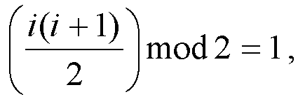
- The method of claim 1, wherein writing into the triangular interleaver comprises:
writing the bits having the odd indexes into the given row in an order from a least significant bit to a most significant bit. - The method of claim 1, wherein writing the bits having the even indexes into the given row comprises:
writing the bits into the given row in an order from a most significant bit to a least significant bit. - The method of claim 1, wherein determining the second number based on the first number comprises:determining the second number H to be a minimum integer which satisfies
 where N represents the first number.
 - The method of claim 1, wherein the predetermined value is 1.
- The method of claim 1, wherein the triangular interleaver forms an upper triangular matrix in an interleaved array, the interleaved array comprising the second number of rows and the second number of columns.
- The method of claim 9, further comprising:
reading, from an ending row in the interleaved array, the written bits row by row in an order from a least significant bit to a most significant bit. - A method of interleaving data in a wireless communication system, comprising:determining, based on a first number of bits in a bit sequence to be interleaved, a second number of rows and the second number of columns in an interleaved array for interleaving the bits;dividing the bit sequence into the second number of subsequences, a difference between numbers of bits in any two successive subsequences of the subsequences being a predetermined value; andwriting the second number of subsequences concurrently into the interleaved array, comprising:writing a starting bit in a subsequence having an index of zero in the second number of subsequences at a predetermined location in a diagonal of the interleaved array, andfor a subsequent subsequence to the subsequence having the index of zero in the second number of subsequences, writing the subsequent subsequence into the interleaved array based on a third number of bits in the subsequent subsequence.
- The method of claim 11, wherein writing the subsequent subsequence into the interleaved array comprises:iteratively performing the following for at least one time, until the third number is equal to zero:in response to the third number being equal to 1, writing a starting bit in the subsequent subsequence at a subsequent location in the diagonal, an offset of the subsequent location relative to the predetermined location being determined based on an index of the subsequent subsequence;andin response to the third number being greater than 1,writing the starting bit in the subsequent subsequence at a first location in the interleaved array, the first location and the predetermined location having a same column index,writing a bit that is subsequent to the starting bit in the subsequent subsequence at a second location in the interleaved array, the second location and the predetermined location having a same row index, andupdating the third number by removing the written bits from the subsequent subsequence.
- The method of claim 12, wherein the subsequent location is determined such that the subsequent location satisfies d1=d0+j-1, where do represents an index of the predetermined location in the diagonal, and j represents an index of the subsequent subsequence.
- The method of claim 12, wherein a row offset of the first location relative to the predetermined location is determined based on an index of the subsequent subsequence.
- The method of claim 14, wherein the first location is determined such that the first location satisfies r1=r0+k, where ro represents a row index of the predetermined location, and k represents an index of the subsequent subsequence.
- The method of claim 12, wherein a column offset of the second location relative to the predetermined location is determined based on an index of the subsequent subsequence.
- The method of claim 16, wherein the second location is determined such that the second location satisfies l1=l0+m, where l0 represents a column index of the predetermined location, and m represents an index of the subsequent subsequence.
- The method of claim 11, wherein the second number of subsequences each comprise consecutive bits of the plurality of bits.
- The method of claim 11, wherein determining the second number based on the first number comprises:determining the second number H to be a minimum integer which satisfies
 where N represents the first number.
 - The method of claim 11, wherein the predetermined location has a row index of zero and a column index of zero.
- The method of claim 11, wherein the predetermined value is 1.
- The method of claim 11, further comprising:
reading, from an ending row in the interleaved array, the written bits row by row in an order from a least significant bit to a most significant bit. - A device for interleaving data in a wireless communication system, comprising:a processor; anda memory having instructions stored thereon, the instructions, when executed by the processor, causing the device to perform the method of any of claims 1-10.
- A device for interleaving data in a wireless communication system, comprising:a processor; anda memory having instructions stored thereon, the instructions, when executed by the processor, causing the device to perform the method of any of claims 11-22.
- A computer readable storage medium comprising machine executable instructions, the machine executable instructions, when executed by a device, causing the device to perform the method of any one of claims 1-10.
- A computer readable storage medium comprising machine executable instructions, the machine executable instructions, when executed by a device, causing the device to perform the method of any one of claims 11-22.
Applications Claiming Priority (2)
| Application Number | Priority Date | Filing Date | Title |
|---|---|---|---|
| CN201710824271.2A CN109495210B (en) | 2017-09-13 | 2017-09-13 | Method, apparatus, and computer-readable storage medium for interleaving data in a wireless communication system |
| PCT/CN2018/105489 WO2019052504A1 (en) | 2017-09-13 | 2018-09-13 | Method and device for interleaving data in wireless communication system, and computer readable storage medium |
Publications (2)
| Publication Number | Publication Date |
|---|---|
| EP3683989A1 true EP3683989A1 (en) | 2020-07-22 |
| EP3683989A4 EP3683989A4 (en) | 2021-06-09 |
Family
ID=65689080
Family Applications (1)
| Application Number | Title | Priority Date | Filing Date |
|---|---|---|---|
| EP18856447.0A Withdrawn EP3683989A4 (en) | 2017-09-13 | 2018-09-13 | Method and device for interleaving data in wireless communication system, and computer readable storage medium |
Country Status (4)
| Country | Link |
|---|---|
| US (1) | US20210376861A1 (en) |
| EP (1) | EP3683989A4 (en) |
| CN (1) | CN109495210B (en) |
| WO (1) | WO2019052504A1 (en) |
Family Cites Families (10)
| Publication number | Priority date | Publication date | Assignee | Title |
|---|---|---|---|---|
| CN1288560C (en) * | 2001-11-05 | 2006-12-06 | 诺基亚有限公司 | Method and apparatus for avoiding aggregation in a communication system by partially filling a block interleaver |
| US7409626B1 (en) * | 2004-07-28 | 2008-08-05 | Ikanos Communications Inc | Method and apparatus for determining codeword interleaver parameters |
| US7657818B2 (en) * | 2005-06-22 | 2010-02-02 | Adaptive Spectrum And Signal Alignment, Inc. | Dynamic minimum-memory interleaving |
| TWI390856B (en) * | 2007-11-26 | 2013-03-21 | Sony Corp | Data processing device and data processing method |
| US9608851B2 (en) * | 2013-03-15 | 2017-03-28 | Jonathan Kanter | Turbo decoding techniques |
| CN106817195B (en) * | 2015-12-02 | 2020-04-21 | 华为技术有限公司 | Method and apparatus for rate matching of polar codes |
| CN106877973B (en) * | 2015-12-10 | 2020-04-14 | 华为技术有限公司 | Polar code processing method and communication device |
| CN106230489B (en) * | 2016-07-15 | 2019-07-16 | 西安电子科技大学 | Polarization code encoding modulation method suitable for any high order modulation |
| CN109495207B (en) * | 2017-09-11 | 2021-08-10 | 上海诺基亚贝尔股份有限公司 | Method and apparatus for interleaving data in wireless communication system |
| CN109600194B (en) * | 2017-09-30 | 2024-06-18 | 华为技术有限公司 | Polar encoding method and encoding device, decoding method and decoding device |
-
2017
- 2017-09-13 CN CN201710824271.2A patent/CN109495210B/en active Active
-
2018
- 2018-09-13 WO PCT/CN2018/105489 patent/WO2019052504A1/en not_active Ceased
- 2018-09-13 EP EP18856447.0A patent/EP3683989A4/en not_active Withdrawn
- 2018-09-13 US US16/647,161 patent/US20210376861A1/en not_active Abandoned
Also Published As
| Publication number | Publication date |
|---|---|
| CN109495210B (en) | 2020-07-31 |
| US20210376861A1 (en) | 2021-12-02 |
| WO2019052504A1 (en) | 2019-03-21 |
| CN109495210A (en) | 2019-03-19 |
| EP3683989A4 (en) | 2021-06-09 |
Similar Documents
| Publication | Publication Date | Title |
|---|---|---|
| US11171741B2 (en) | Polar code transmission method and apparatus | |
| KR102129802B1 (en) | Data transmission method and transmitter | |
| US20190053095A1 (en) | Method and device for transmitting data | |
| US20200186168A1 (en) | Method and device for determining check matrix, and computer storage medium | |
| US11258463B2 (en) | Polar code transmission method and apparatus | |
| US10784895B2 (en) | Inter-block modifications to generate sub-matrix of rate compatible parity check matrix | |
| US11050510B2 (en) | Polar code transmission method and apparatus | |
| WO2018146552A1 (en) | Crc aided decoding of polar codes | |
| EP3566349B1 (en) | Methods and apparatuses for spreading error detection bits in a polar code | |
| EP4040684A2 (en) | Method and apparatus for performing block interleaving for data transmission | |
| US8694871B2 (en) | Iterative decoding method for encoded signal and iterative decoding apparatus for encoded signal | |
| US11381342B2 (en) | Method and device for interleaving data in wireless communication system | |
| KR20190021652A (en) | Apparatus and method for determining polar code in wireless communication system | |
| EP3683989A1 (en) | Method and device for interleaving data in wireless communication system, and computer readable storage medium | |
| CN113574806B (en) | Polarization encoding | |
| CN108631913A (en) | A kind of deinterleaving method and relevant device based on Quasi-cyclic Low-density Parity-check Codes | |
| EP3657708A1 (en) | Coding method, decoding method, device and equipment | |
| US10756762B2 (en) | Method of channel coding for communication systems and apparatus using the same | |
| CN111786680B (en) | Method and device for determining generator matrix | |
| KR102350909B1 (en) | Method and apparatus for error-correcting based on error-correcting code | |
| KR100682243B1 (en) | Error Correction Method of 3D Reed-Solomon Code | |
| WO2024255404A1 (en) | Encoding method and apparatus, decoding method and apparatus, and storage medium | |
| WO2026040603A1 (en) | Communication method, communication apparatus, computer-readable storage medium, chip, and computer program product |
Legal Events
| Date | Code | Title | Description |
|---|---|---|---|
| STAA | Information on the status of an ep patent application or granted ep patent |
Free format text: STATUS: THE INTERNATIONAL PUBLICATION HAS BEEN MADE |
|
| PUAI | Public reference made under article 153(3) epc to a published international application that has entered the european phase |
Free format text: ORIGINAL CODE: 0009012 |
|
| STAA | Information on the status of an ep patent application or granted ep patent |
Free format text: STATUS: REQUEST FOR EXAMINATION WAS MADE |
|
| 17P | Request for examination filed |
Effective date: 20200403 |
|
| AK | Designated contracting states |
Kind code of ref document: A1 Designated state(s): AL AT BE BG CH CY CZ DE DK EE ES FI FR GB GR HR HU IE IS IT LI LT LU LV MC MK MT NL NO PL PT RO RS SE SI SK SM TR |
|
| AX | Request for extension of the european patent |
Extension state: BA ME |
|
| DAV | Request for validation of the european patent (deleted) | ||
| DAX | Request for extension of the european patent (deleted) | ||
| A4 | Supplementary search report drawn up and despatched |
Effective date: 20210507 |
|
| RIC1 | Information provided on ipc code assigned before grant |
Ipc: H04L 1/00 20060101AFI20210430BHEP |
|
| STAA | Information on the status of an ep patent application or granted ep patent |
Free format text: STATUS: THE APPLICATION IS DEEMED TO BE WITHDRAWN |
|
| 18D | Application deemed to be withdrawn |
Effective date: 20230401 |