EP3683984A1 - Array antenna calibration method and device - Google Patents
Array antenna calibration method and device Download PDFInfo
- Publication number
- EP3683984A1 EP3683984A1 EP18853726.0A EP18853726A EP3683984A1 EP 3683984 A1 EP3683984 A1 EP 3683984A1 EP 18853726 A EP18853726 A EP 18853726A EP 3683984 A1 EP3683984 A1 EP 3683984A1
- Authority
- EP
- European Patent Office
- Prior art keywords
- calibrated
- array antenna
- weight vector
- standard
- calibration
- Prior art date
- Legal status (The legal status is an assumption and is not a legal conclusion. Google has not performed a legal analysis and makes no representation as to the accuracy of the status listed.)
- Granted
Links
Images



Classifications
-
- H—ELECTRICITY
- H01—ELECTRIC ELEMENTS
- H01Q—ANTENNAS, i.e. RADIO AERIALS
- H01Q3/00—Arrangements for changing or varying the orientation or the shape of the directional pattern of the waves radiated from an antenna or antenna system
-
- H—ELECTRICITY
- H04—ELECTRIC COMMUNICATION TECHNIQUE
- H04B—TRANSMISSION
- H04B17/00—Monitoring; Testing
- H04B17/20—Monitoring; Testing of receivers
- H04B17/21—Monitoring; Testing of receivers for calibration; for correcting measurements
- H04B17/22—Monitoring; Testing of receivers for calibration; for correcting measurements for calibration of the receiver components
- H04B17/221—Monitoring; Testing of receivers for calibration; for correcting measurements for calibration of the receiver components of receiver antennas, e.g. as to amplitude or phase
-
- H—ELECTRICITY
- H01—ELECTRIC ELEMENTS
- H01Q—ANTENNAS, i.e. RADIO AERIALS
- H01Q3/00—Arrangements for changing or varying the orientation or the shape of the directional pattern of the waves radiated from an antenna or antenna system
- H01Q3/26—Arrangements for changing or varying the orientation or the shape of the directional pattern of the waves radiated from an antenna or antenna system varying the relative phase or relative amplitude of energisation between two or more active radiating elements; varying the distribution of energy across a radiating aperture
- H01Q3/267—Phased-array testing or checking devices
-
- H—ELECTRICITY
- H04—ELECTRIC COMMUNICATION TECHNIQUE
- H04B—TRANSMISSION
- H04B17/00—Monitoring; Testing
- H04B17/10—Monitoring; Testing of transmitters
- H04B17/11—Monitoring; Testing of transmitters for calibration
- H04B17/12—Monitoring; Testing of transmitters for calibration of transmit antennas, e.g. of the amplitude or phase
-
- H—ELECTRICITY
- H04—ELECTRIC COMMUNICATION TECHNIQUE
- H04B—TRANSMISSION
- H04B7/00—Radio transmission systems, i.e. using radiation field
- H04B7/02—Diversity systems; Multi-antenna system, i.e. transmission or reception using multiple antennas
- H04B7/04—Diversity systems; Multi-antenna system, i.e. transmission or reception using multiple antennas using two or more spaced independent antennas
- H04B7/06—Diversity systems; Multi-antenna system, i.e. transmission or reception using multiple antennas using two or more spaced independent antennas at the transmitting station
- H04B7/0613—Diversity systems; Multi-antenna system, i.e. transmission or reception using multiple antennas using two or more spaced independent antennas at the transmitting station using simultaneous transmission
- H04B7/0615—Diversity systems; Multi-antenna system, i.e. transmission or reception using multiple antennas using two or more spaced independent antennas at the transmitting station using simultaneous transmission of weighted versions of same signal
- H04B7/0617—Diversity systems; Multi-antenna system, i.e. transmission or reception using multiple antennas using two or more spaced independent antennas at the transmitting station using simultaneous transmission of weighted versions of same signal for beam forming
-
- H—ELECTRICITY
- H04—ELECTRIC COMMUNICATION TECHNIQUE
- H04B—TRANSMISSION
- H04B17/00—Monitoring; Testing
- H04B17/0082—Monitoring; Testing using service channels; using auxiliary channels
- H04B17/0085—Monitoring; Testing using service channels; using auxiliary channels using test signal generators
Definitions
- the present disclosure relates to the field of mobile communications, and particularly to a method and device for calibrating an array antenna.
- An active array antenna is a system that receives or transmits electromagnetic waves by directly connecting an active circuit to each element of the array antenna.
- the active array antenna enables beamforming, and calibrates channels corresponding to each element to ensure the consistence of the amplitudes and phases of the elements, thereby ensuring the effectiveness of the beamforming function.
- OTA over the air
- Embodiments of the disclosure provide a method and a device for calibrating an array antenna, which calibrate the array antenna in real time in an open calibration environment.
- an embodiment of the disclosure provides a method for calibrating an array antenna.
- the method includes: transmitting a first calibration signal to an array antenna to be calibrated by using a testing antenna oriented in a standard beam direction, and determining differences in both amplitude and phase between a first calibration signal received by a central channel of the array antenna to be calibrated and a first calibration signal received by each channel of the array antenna to be calibrated, according to the first calibration signal transmitted by the testing antenna oriented in the standard beam direction and received by the array antenna to be calibrated via each channel; where the central channel is a channel corresponding to a central element of the array antenna to be calibrated; and calibrating an initial beam weight vector matrix according to the differences in both the amplitude and the phase to obtain a compensation beam weight vector matrix, where the initial beam weight vector matrix is determined according to a preset directional angle of each beam direction and each group of initial beam weight vectors corresponds to one of beam directions.
- calibrating the initial beam weight vector matrix according to the differences in both the amplitude and the phase to obtain the compensation beam weight vector matrix includes: compensating for each group of initial beam weight vectors in the initial beam weight vector matrix, respectively, according to the differences in both the amplitude and the phase to obtain the compensation beam weight vector matrix.
- the method further includes: transmitting a second calibration signal at a specified power rating to the array antenna to be calibrated by using the testing antenna oriented in the standard beam direction, and determining a standard beam gain of the second calibration signal transmitted by the testing antenna oriented in the standard beam direction and received by the array antenna to be calibrated via each channel according to the compensation beam weight vector matrix; transmitting the second calibration signal at the specified power rating to the testing antenna oriented in the standard beam direction by using the array antenna to be calibrated, and determining a standard signal power of the second calibration signal transmitted by the array antenna to be calibrated and received by the testing antenna oriented in the standard beam direction; and for each testing antenna oriented in a beam direction different from the standard beam direction: calibrating each channel of the array antenna to be calibrated in a currently selected beam direction by using a currently selected testing antenna according to the standard beam gain and the standard signal power corresponding to the testing antenna oriented in the
- determining the standard beam gain of the second calibration signal transmitted by the testing antenna oriented in the standard beam direction and received by the array antenna to be calibrated via each channel according to the compensation beam weight vector matrix includes: determining a compensation beam weight vector corresponding to the testing antenna oriented in the standard beam direction according to the compensation beam weight vector matrix; and determining the standard beam gain of the second calibration signal transmitted by the testing antenna oriented in the standard beam direction and received by each channel of the array antenna to be calibrated according to the compensation beam weight vector.
- each channel of the array antenna to be calibrated includes a reception channel and a transmission channel; and after calibrating the initial beam weight vector matrix according to the differences in both the amplitude and the phase to obtain the compensation beam weight vector matrix, the method further includes: updating the initial beam weight vector matrix of each channel of the array antenna to be calibrated according to the compensation beam weight vector matrix, where each updated reception channel of the array antenna to be calibrated corresponds to a compensation reception beam weight vector matrix, and each updated transmission channel corresponds to a compensation transmission beam weight vector matrix, and the compensation reception beam weight vector matrix and the compensation transmission beam weight vector matrix are the compensation beam weight vector matrix, respectively.
- calibrating each channel of the array antenna to be calibrated in a currently selected beam direction by using a currently selected testing antenna according to the standard beam gain and the standard signal power corresponding to the testing antenna oriented in the standard beam direction includes: transmitting a second calibration signal at a specified power rating to the array antenna to be calibrated by using the testing antenna oriented in the currently selected beam direction, and determining a beam gain of the second calibration signal transmitted by the testing antenna and received by the array antenna to be calibrated according to the compensation beam weight vector corresponding to the testing antenna; determining if the difference between the beam gain and the standard beam gain is out of a first preset range; and when the difference between the beam gain and the standard beam gain is determined to be out of the first preset range, adjusting a directional angle of the currently selected beam direction, updating the compensation reception beam weight vector corresponding to an originally selected beam direction according to an adjusted beam direction, and re-calculating the beam gain of the second calibration signal according to an updated compensation reception beam weight vector until the difference between the beam gain and the standard beam gain falls within the
- the method further includes: determining that calibration, in the currently selected beam direction, of each reception channel of the array antenna to be calibrated is completed when the difference between the beam gain and the standard beam gain falls within the first preset range, transmitting the second calibration signal at the specified power rating to the testing antenna oriented in the currently selected beam direction by using the array antenna to be calibrated, determining a signal power of the second calibration signal received by the testing antenna and received by the array antenna to be calibrated and determining if a difference between the signal power and the standard signal power is out of a second preset range; and when the difference between the signal power and the standard signal power is determined to be out of the second preset range, re-calibrating each reception channel of the array antenna to be calibrated in the currently selected beam direction; or when the difference between the signal power and the standard signal power is determined to be fall within the second preset range, determining that calibration, in the currently selected beam direction, of each transmission channel of the array antenna to be calibrated is completed.
- the method before adjusting the directional angle of the currently selected beam direction when the difference between the beam gain and the standard beam gain is determined to be out of the first preset range, the method further includes: determining if a number of calibration, in the currently selected beam direction, of each reception channel of the array antenna to be calibrated is greater than a preset number; and after determining if the number of calibration, in the currently selected the beam direction, of each reception channel of the array antenna to be calibrated is greater than the preset number, the method further includes: adjusting the directional angle of the currently selected beam direction when the number of calibration is determined to be smaller than or equal to the preset number; or transmitting a warning signal for reception channel calibration when the number of calibration is determined to be greater than the preset number.
- the method before re-calibrating each reception channel of the array antenna to be calibrated in the currently selected beam direction, when the difference between the signal power and the standard signal power is determined to be out of the second preset range, the method further includes: determining if a number of calibration, in the currently selected beam direction, of each transmission channel of the array antenna to be calibrated is greater than a preset number; and after determining if the number of calibration, in the currently selected beam direction, of each transmission channel of the array antenna to be calibrated is greater than the preset number, the method further includes: when the number of calibration is determined to be smaller than or equal to the preset number, re-calibrating, in the currently selected beam direction, each reception channel of the array antenna to be calibrated; or, when the number of calibration is determined to be greater than the preset number, transmitting a warning signal for transmission channel calibration.
- an embodiment of the disclosure provides a device for calibrating an array antenna.
- the device includes: a first processing unit, configured to transmit a first calibration signal to an array antenna to be calibrated by using a testing antenna oriented in a standard beam direction, and determine differences in both amplitude and phase between a first calibration signal received by a central channel of the array antenna to be calibrated and a first calibration signal received by each channel of the array antenna to be calibrated, according to the first calibration signal transmitted by the testing antenna oriented in the standard beam direction and received by the array antenna to be calibrated via each channel; where the central channel is a channel corresponding to a central element of the array antenna to be calibrated; and a calibration unit, configured to calibrate an initial beam weight vector matrix according to the differences in both the amplitude and the phase to obtain a compensation beam weight vector matrix, where the initial beam weight vector matrix is determined according to a preset directional angle of each beam direction and each group of initial beam weight vectors corresponds to one of beam directions.
- the calibration unit when calibrating the initial beam weight vector matrix according to the differences in both the amplitude and the phase to obtain the compensation beam weight vector matrix, is configured to compensate for each group of initial beam weight vectors in the initial beam weight vector matrix, respectively, according to the differences in both the amplitude and the phase to obtain the compensation beam weight vector matrix.
- the device further includes a second processing unit.
- the second processing unit is configured to: transmit a second calibration signal at a specified power rating to the array antenna to be calibrated by using the testing antenna oriented in the standard beam direction, and determine a standard beam gain of the second calibration signal transmitted by the testing antenna oriented in the standard beam direction and received by the array antenna to be calibrated via each channel according to the compensation beam weight vector matrix; transmit the second calibration signal at the specified power rating to the testing antenna oriented in the standard beam direction by using the array antenna to be calibrated, and determine a standard signal power of the second calibration signal transmitted by the array antenna to be calibrated and received by the testing antenna oriented in the standard beam direction; and for each testing antenna oriented in a beam direction different from the standard beam direction, calibrate each channel of the array antenna to be calibrated in a currently selected beam direction by using a currently selected testing antenna according to the standard beam gain and the standard signal power
- the second processing unit when determining the standard beam gain of the second calibration signal transmitted by the testing antenna oriented in the standard beam direction and received by the array antenna to be calibrated via each channel according to the compensation beam weight vector matrix, is configured to: determine a compensation beam weight vector corresponding to the testing antenna oriented in the standard beam direction according to the compensation beam weight vector matrix; and determine the standard beam gain of the second calibration signal transmitted by the testing antenna oriented in the standard beam direction and received by each channel of the array antenna to be calibrated according to the compensation beam weight vector.
- each channel of the array antenna to be calibrated includes a reception channel and a transmission channel.
- the device further includes an updating unit.
- the updating unit is configured to: update the initial beam weight vector matrix of each channel of the array antenna to be calibrated according to the compensation beam weight vector matrix, where each updated reception channel of the array antenna to be calibrated corresponds to a compensation reception beam weight vector matrix, each updated transmission channel corresponds to a compensation transmission beam weight vector matrix, and the compensation reception beam weight vector matrix and the compensation transmission beam weight vector matrix are the compensation beam weight vector matrix, respectively.
- the second processing unit when calibrating each channel of the array antenna to be calibrated in a currently selected beam direction by using a currently selected testing antenna according to the standard beam gain and the standard signal power corresponding to the testing antenna oriented in the standard beam direction, is configured to: transmit a second calibration signal at a specified power rating to the array antenna to be calibrated by using the testing antenna oriented in the currently selected beam direction, and determine a beam gain of the second calibration signal transmitted by the testing antenna and received by the array antenna to be calibrated according to the compensation beam weight vector corresponding to the testing antenna; determine if the difference between the beam gain and the standard beam gain is out of a first preset range; and when the difference between the beam gain and the standard beam gain is determined to be out of the first preset range, adjust a directional angle of the currently selected beam direction, update the compensation reception beam weight vector corresponding to an originally selected beam direction according to an adjusted beam direction, and re-calculate the beam gain of the second calibration signal according to an updated compensation reception beam weight vector until the difference between the beam gain and the standard
- the second processing unit is further configured to: determine that calibration, in the currently selected beam direction, of each reception channel of the array antenna to be calibrated is completed when the difference between the beam gain and the standard beam gain falls within the first preset range, transmit the second calibration signal at the specified power rating to the testing antenna oriented in the currently selected beam direction by using the array antenna to be calibrated, determine a signal power of the second calibration signal received by the testing antenna and received by the array antenna to be calibrated, and determine if a difference between the signal power and the standard signal power is out of a second preset range; and when the difference between the signal power and the standard signal power is determined to be out of the second preset range, re-calibrate each reception channel of the array antenna to be calibrated in the currently selected beam direction; or when the difference between the signal power and the standard signal power is determined to be fall within the second preset range, determine that calibration, in the currently selected beam direction, of each transmission channel of the array antenna to be calibrated is completed.
- the device further includes a second determining unit.
- the second determining unit Before each reception channel of the array antenna to be calibrated is re-calibrated in the currently selected beam direction, when the difference between the signal power and the standard signal power is determined to be out of the second preset range, the second determining unit is configured to: determine if a number of calibration, in the currently selected beam direction, of each transmission channel of the array antenna to be calibrated is greater than a preset number; and after determining if the number of calibration, in the currently selected beam direction, of each transmission channel of the array antenna to be calibrated is greater than the preset number, the second determining unit is configured to: when the number of calibration is determined to be smaller than or equal to the preset number, re-calibrate, in the currently selected beam direction, each reception channel of the array antenna to be calibrated; or, when the number of calibration is determined to be greater than the preset number, transmit a warning signal for transmission channel calibration.
- an embodiment of the disclosure provides an electronic device.
- the electronic device includes one or more processers and one or more computer-readable mediums.
- the one or more computer-readable mediums store a program for calibrating an array antenna.
- the one or more processers are configured to execute the program to perform the method according to any one of the implementation modes of the embodiment in the first aspect.
- an embodiment of the disclosure provides one or more computer-readable mediums.
- the one or more computer-readable mediums store a program for calibrating an array antenna.
- a communication device performs the method according to any one of the implementation modes of the embodiment in the first aspect.
- a first calibration signal is transmitted to the array antenna to be calibrated via the testing antenna oriented in the standard beam direction, the differences in amplitude and phase between the first calibration signal received via the central channel and the first calibration signal received by each channel are determined according to the first calibration signal received by each channel of the array antenna to be calibrated, and the initial beam weight vector matrix is calibrated according to the differences in both the amplitude and the phase to obtain the compensation beam weight vector matrix.
- the initial beam weight vector matrix is determined by preset directional angles of various beam directions and each group of initial beam weight vectors corresponds to a beam direction.
- GSM global system of mobile communication
- CDMA code division multiple access
- WCDMA wideband code division multiple access
- GPRS general packet radio service
- LTE long term evolution
- LTE-A advanced long term evolution
- UMTS universal mobile telecommunication system
- NR new radio
- UE user equipment
- MS mobile station
- RAN radio access network
- the user equipment can be a mobile phone (or a cell phone) or a computer having a function of radio communication, or the user equipment can be a portable, pocket, handheld, built-in-computer, or on-vehicle mobile apparatus.
- a base station e.g., an access point
- the base station can be an apparatus in an access network that communicates with a radio terminal over one or more sectors via an air interface.
- the base station can be configured to convert a received air frame into an internet protocol (hereinafter "IP") packet and convert a received IP packet into an air frame, and operate as a router between the radio terminal and the remaining components of the access network, where the remaining components of the access network can include an IP network.
- IP internet protocol
- the base station can further coordinate attribute management of the air interface.
- the base station can be a base transceiver station (hereinafter "BTS") in a GSM or CDMA system, a Node B in a TD-SCDMA or a WCDMA system, an evolutional Node B (or referred to as eNodeB, eNB or e-Node B) in an LTE system, or a base station (hereinafter "gNB”) in a 5G NR system, although the disclosure is not limited thereto.
- BTS base transceiver station
- gNB base station
- embodiments of the disclosure redesign a method for calibrating the array antenna.
- the method includes: transmitting a first calibration signal to an array antenna to be calibrated by using a testing antenna oriented in a standard beam direction; determining differences in both amplitude and phase between a first calibration signal received by a central channel of the array antenna to be calibrated and a first calibration signal received by each channel of the array antenna to be calibrated, according to the first calibration signal transmitted by the testing antenna oriented in the standard beam direction and received by the array antenna to be calibrated via each channel; and calibrating an initial beam weight vector matrix based on the differences in both the amplitude and the phase to obtain a compensation beam weight vector matrix; where the initial beam weight vector matrix is determined according to a preset directional angle of each beam direction and each group of initial beam weight vectors corresponds to one of beam directions.
- the calibration environment where a plurality of testing antennas are placed corresponding to different beam directions of the array antenna to be calibrated is taken as an example herein.
- one of the testing antennas is placed corresponding to one of beam directions (hereinafter "a testing antenna oriented in a beam direction").
- Each of the beam directions has a directional angle, and the directional angle includes at least an azimuth on the horizontal plane and a tilt on the vertical plane.
- a testing antenna oriented in a beam direction corresponds to a group of the azimuth and the tilt. Azimuths and tilts corresponding to testing antennas oriented in different beam directions are different.
- the testing antennas connected by dotted lines represent the testing antennas placed on the horizontal plane (x-y). Angles between the testing antennas on the horizontal plane and the array antenna to be calibrated are azimuths, which are denoted by ⁇ .
- the testing antennas connected by dashed lines represent the testing antennas on the vertical plane (y-z). Angles between the testing antennas on the vertical plane and the array antenna to be calibrated are tilts, which are denoted by ⁇ .
- the calibration environment can be re-used, instead of re-building a calibration environment whenever a calibration of an array antenna is to be performed.
- a method for calibrating an array antenna includes steps 200 and 210.
- Step 200 transmitting a first calibration signal to an array antenna to be calibrated by using a testing antenna oriented in a standard beam direction, and determining differences in both amplitude and phase between a first calibration signal received by a central channel of the array antenna to be calibrated and a first calibration signal received by each channel of the array antenna to be calibrated, according to the first calibration signal transmitted by the testing antenna oriented in the standard beam direction and received by the array antenna to be calibrated via each channel; where the central channel is a channel corresponding to the central element of the array antenna to be calibrated.
- the testing antenna oriented in the standard beam direction is a testing antenna on the same horizontal line of the array antenna to be calibrated. That is, the azimuth and tilt of the directional angle corresponding to the standard beam direction are zero.
- the central channel refers to the channel corresponding to the central element of the array antenna to be calibrated and is one of the channels of the array antenna to be calibrated.
- Step 210 calibrating an initial beam weight vector matrix according to the differences in both the amplitude and the phase to obtain a compensation beam weight vector matrix, where the initial beam weight vector matrix is determined according to a preset directional angle of each beam direction and each group of initial beam weight vectors in the initial beam weight vector matrix corresponds to one of beam directions.
- the compensation beam weight vector matrix is obtained through the steps 200-201, so that each channel of the array antenna is preliminarily calibrated in the standard beam direction.
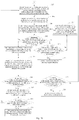
- a method for calibrating an array antenna according to another implementation mode of the embodiment of the disclosure includes steps 300-321.
- Step 300 determining an initial beam weight vector matrix of an array antenna to be calibrated according to a preset directional angle of each beam direction; where each group of the initial beam weight vectors in the initial beam weight vector matrix corresponds to one of the beam directions.
- the initial beam weight vector matrix of the array antenna to be calibrated is determined according to directional angle of each beam direction in the current calibration environment; where each group of the initial beam weight vectors in the initial beam weight vector matrix corresponds to one of the beam directions, and a direction of each group of the initial beam weight vectors is the corresponding directional angle respectively.
- the array antenna to be calibrated has the function of transmitting and reception signals. Therefore, the array antenna to be calibrated has reception channels and transmission channels.
- the initial reception beam weight vector matrix corresponding to the reception channels of the array antenna to be calibrated there is an initial reception beam weight vector matrix corresponding to the transmission channels.
- the initial transmission beam weight vector matrix and the initial transmission beam weight vector matrix are the same and equal to the initial beam weight vector matrix.
- Step 301 transmitting a first calibration signal to the array antenna to be calibrated by using a testing antenna oriented in a standard beam direction.
- the testing antenna oriented in the standard beam direction is used to transmit the first calibration signal to the array antenna to be calibrated.
- the directional angle of the standard beam direction is 0, i.e., the azimuth and tilt are zero respectively.
- the first calibration signal may be a single tone calibration signal.
- the array antenna to be calibrated receives the first calibration signal transmitted by the testing antenna oriented in the standard beam direction through a plurality of channels, and uses the first calibration signal received by the central channel as a reference to determine the differences in both amplitude and phase between the first calibration signal received by the central channel and those received by each of the plurality of channels, respectively.
- the central channel is one of the plurality of channels which corresponds to a central element of the array antenna to be calibrated.
- the first calibration signals received by the array antenna to be calibrated through N channels are x 0 ( t ), x 1 ( t ), ..., x N -1 ( t ), and the first calibration signal received by the central channel corresponding to the central element of the array antenna to be calibrated is x 0 ( t ), which is used as a reference.
- Step 303 calibrating the initial beam weight vector matrix according to the differences in the amplitude and the phase to obtain a compensation beam weight vector matrix.
- each group of initial beam weight vectors in the initial beam weight vector matrix are compensated for according to the differences to form the compensation beam weight vector matrix.
- obtained corresponding differences in amplitude and phase, e are used to compensate for the errors in amplitude and phase of the initial beam weight vector matrix W to obtain the compensation beam weight vector matrix W c .
- the compensation may be dot product operation.
- the testing antenna oriented in the standard beam direction is used to transmit the first calibration signal to the array antenna to be calibrated, then the differences in amplitude and phase among the first calibration signals received by the plurality of channels of the array antenna to be calibrated are determined and are used to compensate for the initial beam weight vector matrix to calibrate the amplitudes and phases of each channel of the array antenna to be calibrated in the standard beam direction.
- the compensation beam weight vector matrix is used to update the initial beam weight vector matrix of each of the channels of the array antenna to be calibrated. After the update, there is a compensation reception beam weight vector matrix corresponding to each of the reception channels of the array antenna to be calibrated, and a compensation transmission beam weight vector matrix corresponding to each of the transmission channels of the array antenna to be calibrated.
- the compensation reception beam weight vector matrix and the compensation transmission beam weight vector matrix are equal to the compensation beam weight vector matrix, respectively.
- Step 304 transmitting a second calibration signal at a specified power rating to the array antenna to be calibrated by using the testing antenna oriented in the standard beam direction.
- the testing antenna oriented in the standard beam direction is used to transmit the second calibration signal at the specified power rating to the array antenna to be calibrated.
- Step 305 receiving the second calibration signal transmitted by the testing antenna oriented in the standard beam direction via the plurality of channels, and determining a standard beam gain of the second calibration signals received by the array antenna to be calibrated via the plurality of channels according to the corresponding compensation beam weight vector.
- the array antenna to be calibrated receives the second calibration signal transmitted by the testing antenna oriented in the standard beam direction via the plurality of channels, and determines the compensation beam weight vector corresponding to the testing antenna oriented in the standard beam direction according to the obtained compensation beam weight vector matrix. Then the standard beam gain of the second calibration signals received by the array antenna to be calibrated via the plurality of channels is determined according to the corresponding compensation beam weight vectors.
- the obtained standard beam gain is the reception beamforming index of the array antenna to be calibrated in the standard beam direction.
- Step 306 transmitting the second calibration signal at the specified power rating to the testing antenna oriented in the standard beam direction by using the array antenna to be calibrated, and determining a standard signal power of the second calibration signal received by the testing antenna oriented in the standard beam direction.
- the array antenna to be calibrated transmits the second calibration signal at the specified power rating to the testing antenna oriented in the standard beam direction via the plurality of channels and the standard signal power corresponding to the second calibration signal received by the testing antenna oriented in the standard beam direction is determined.
- the method of determining the standard signal power of the second calibration signal received by the testing antenna oriented in the standard beam direction may be an existing method and is not introduced further herein.
- the array antenna to be calibrated transmits the second calibration signal at the power rating of P 0 , and the standard signal power corresponding to the second calibration signal received by the testing antenna oriented in the standard beam direction is P B .
- the obtained standard signal power is the transmitting beamforming index of the array antenna to be calibrated in the standard beam direction.
- Step 307 determining a plurality of testing antennas oriented in beam directions different from the standard beam direction, and selecting a testing antenna corresponding to one of beam directions with respect to which calibration has not been performed.
- the channels of the array antenna to be calibrated are to be calibrated in different beam directions to rectify the channel errors.
- the channels of the array antenna to be calibrated (including the reception channels and the transmission channels) are calibrated in the standard beam direction to obtain the compensation beam weight vector matrix corresponding to each channel, and then each channel of the array antenna to be calibrated is calibrated in the other beam directions according to the standard beam direction.
- a testing antenna corresponding to a beam direction with respect to which no calibration has been performed, among the plurality of testing antennas oriented in all the beam directions different from the standard beam direction, is selected to perform the operations below.
- Step 308 transmitting the second calibration signal at the specified power rating to the array antenna to be calibrated by using the selected testing antenna.
- the testing antenna oriented in the currently selected beam direction is used to transmit the second calibration signal to the array antenna to be calibrated.
- Step 309 determining a beam gain of the second calibration signals received by the array antenna to be calibrated and transmitted by the testing antenna according to the compensation beam weight vector corresponding to the currently selected testing antenna.
- the array antenna to be calibrated receives the transmitted second calibration signals via the plurality of channels.
- the compensation beam weight vector corresponding to the testing antenna oriented in the currently selected beam direction is determined according to the obtained compensation beam weight vector matrix.
- the beam gain of the second calibration signals received by array antenna to be calibrated via the plurality of channels is determined according to compensation beam weight vector.
- Step 310 determining whether a difference between the beam gain corresponding to the currently selected beam direction and the standard beam gain falls within a first preset range. If so, step 311 is performed, otherwise step 312 is performed.
- the step 311 is performed. Otherwise, the step 312 is performed.
- the second calibration signals are transmitted at the power rating to the array antenna to be calibrated by the testing antenna oriented in the currently selected beam direction and the testing antenna oriented in the standard beam direction, respectively, to determine the difference between the beams gains of the array antenna to be calibrated when calibration signals of the same power transmitted from different beam directions are received by the reception channels of the array antenna to be calibrated.
- Step 311 determining that the calibration, in the currently selected beam direction, of the plurality of reception channels of the array antenna to be calibrated is completed.
- the currently selected beam direction is ⁇ k , ⁇ k , then the compensation reception beam weight vector w 1 ( ⁇ k , ⁇ k ) in the compensation reception beam weight vector matrix W ' RX does not need to be calibrated any more.
- Step 312 determining if the number of calibration, in the currently selected beam direction, of the reception channels of the array antenna to be calibrated is greater than a preset number. If so, step 313 is performed, otherwise step 314 is performed.
- Step 313 transmitting a warning signal for reception channel calibration.
- the calibration has been performed too many times when the number of calibration, in the currently selected beam direction, of the reception channels of the array antenna to be calibrated is greater than the preset number, and a warning signal for reception channel calibration may be transmitted.
- Step 314 adjusting a directional angle of the currently selected beam direction and updating the compensation reception beam weight vector corresponding to the originally selected beam direction according to the adjusted directional angle.
- the number of calibration, in the currently selected beam direction, of the reception channels of the array antenna to be calibrated is not greater than the preset number
- the differences in amplitude and phase between the second calibration signal received by the central channel and the second calibration signals received by the plurality of channels are determined
- the directional angel of the currently selected beam direction is adjusted according to a preset angle
- the compensation reception beam weight vector corresponding to the currently selected beam direction is updated according to the differences in amplitude and phase and the adjusted directional angle.
- the differences in amplitude and phase, e k , between the second calibration signal received by the central channel and the second calibration signals received by the plurality of channels are calculated as follows.
- the second calibration signals received by the array antenna to be calibrated via N channels are y 0 ( t ), y 1 ( t ),..., y N-1 ( t ), and the second calibration signal received by the central channel corresponding to the central element of the array antenna to be calibrated is y 0 ( t ), which is used as a reference.
- e k [1, e 1, e 2 ,...,e N -1 ] T , where "1" represents the difference in amplitude and phase between the signals received by the central channel itself.
- the directional angle of the currently selected beam direction is then adjusted according to the preset angle.
- the preset angle is 2.5° and the directional angle corresponding to the currently selected beam direction is ( ⁇ k , ⁇ k ). Then the adjusted directional angle ( ⁇ , ⁇ ) satisfies ( ⁇ , ⁇ ) ⁇ [ ⁇ k - 2.5°, ⁇ k + 2.5°] ⁇ [ ⁇ k - 2.5°, ⁇ k + 2.5°].
- the compensation reception beam weight vector corresponding to the originally selected beam direction is updated according to the obtained differences in amplitude and phase and the adjusted directional angle.
- step 309 is performed again.
- Step 315 transmitting the second calibration signal at the specified power rating to the array antenna to be calibrated by using the currently selected testing antenna, and determining the signal power of the second calibration signals received by the array antenna to be calibrated.
- the transmission channels of the array antenna to be calibrated are calibrated in the currently selected beam direction.
- the testing antenna oriented in the currently selected beam direction is used to transmit the second calibration signal at the specified power rating to the array antenna to be calibrated and the signal power of the second calibration signals received by the array antenna to be calibrated is determined.
- the array antenna to be calibrated transmits the second calibration signal at the power rating of P 0
- the standard signal power corresponding to the second calibration signals received by the testing antenna oriented in the currently selected beam direction is P c .
- step 317 determining whether the difference between the signal power corresponding to the second calibration signal transmitted by the transmission channels of the array antenna to be calibrated and received by the currently selected testing antenna and the standard signal power corresponding to the second calibration signal transmitted by the transmission channels of the array antenna to be calibrated and received by the testing antenna oriented in the standard beam direction falls within the second preset range, and if so, step 317 is performed, otherwise step 318 is performed.
- the calibration, in the currently selected beam direction, of each transmission channel of the array antenna to be calibrated is determined to be completed. That is, there's no need to further calibrate the compensation transmission beam weight vector corresponding to the currently selected beam direction in the above compensation transmission beam weight vector matrix.
- Step 318 determining if the number of calibration, in the currently selected beam direction, of the transmission channels of the array antenna to be calibrated is greater than a preset number. If so, performing step 319, otherwise returning to the step 308.
- Step 319 transmitting a warning signal for transmission channel calibration.
- each transmission channel of the array antenna to be calibrated is greater than the preset number, it means that the transmission channels have been calibrated for too many times and the warning signal for transmission channel calibration may be transmitted.
- Step 320 determining if there's any beam direction with respect to which the array antenna to be calibrated has not been calibrated. If so, performing the step 307, otherwise performing step 321.
- an embodiment of the disclosure provides a device for calibrating an array antenna.
- the device at least includes a first processing unit 41 and a calibration unit 42.
- the first processing unit 41 is configured to transmit a first calibration signal to an array antenna to be calibrated by using a testing antenna oriented in a standard beam direction, and determine differences in both amplitude and phase between a first calibration signal received by a central channel of the array antenna to be calibrated and a first calibration signal received by each channel of the array antenna to be calibrated, according to the first calibration signal transmitted by the testing antenna oriented in the standard beam direction and received by the array antenna to be calibrated via each channel; wherein the central channel is a channel corresponding to a central element of the array antenna to be calibrated.
- the calibration unit 42 is configured to calibrate an initial beam weight vector matrix according to the differences in both the amplitude and the phase to obtain a compensation beam weight vector matrix, wherein the initial beam weight vector matrix is determined according to a preset directional angle of each beam direction and each group of initial beam weight vectors corresponds to one of beam directions.
- the second processing unit 43 when determining the standard beam gain of the second calibration signal transmitted by the testing antenna oriented in the standard beam direction and received by the array antenna to be calibrated via each channel according to the compensation beam weight vector matrix, is configured to: determine a compensation beam weight vector corresponding to the testing antenna oriented in the standard beam direction according to the compensation beam weight vector matrix; and determine the standard beam gain of the second calibration signal transmitted by the testing antenna oriented in the standard beam direction and received by each channel of the array antenna to be calibrated according to the compensation beam weight vector.
- each channel of the array antenna to be calibrated includes a reception channel and a transmission channel.
- the device further includes an updating unit 44.
- the updating unit 44 is configured to: update the initial beam weight vector matrix of each channel of the array antenna to be calibrated according to the compensation beam weight vector matrix, where each updated reception channel of the array antenna to be calibrated corresponds to a compensation reception beam weight vector matrix, each updated transmission channel corresponds to a compensation transmission beam weight vector matrix, and the compensation reception beam weight vector matrix and the compensation transmission beam weight vector matrix are the compensation beam weight vector matrix, respectively.
- the second processing unit 43 is configured to: transmit a second calibration signal at a specified power rating to the array antenna to be calibrated by using the testing antenna oriented in the currently selected beam direction, and determine a beam gain of the second calibration signal transmitted by the testing antenna and received by the array antenna to be calibrated according to the compensation beam weight vector corresponding to the testing antenna; determine if the difference between the beam gain and the standard beam gain is out of a first preset range; and when the difference between the beam gain and the standard beam gain is determined to be out of the first preset range, adjust a directional angle of the currently selected beam direction, update the compensation reception beam weight vector corresponding to an originally selected beam direction according to an adjusted beam direction, and re-calculate the beam gain of the second calibration signal according to an updated compensation reception beam weight vector until the difference between the beam gain and the
- the second processing unit 43 is further configured to: determine that calibration, in the currently selected beam direction, of each reception channel of the array antenna to be calibrated is completed when the difference between the beam gain and the standard beam gain falls within the first preset range, transmit the second calibration signal at the specified power rating to the testing antenna oriented in the currently selected beam direction by using the array antenna to be calibrated, determine a signal power of the second calibration signal received by the testing antenna and received by the array antenna to be calibrated, and determine if a difference between the signal power and the standard signal power is out of a second preset range; and when the difference between the signal power and the standard signal power is determined to be out of the second preset range, re-calibrate each reception channel of the array antenna to be calibrated in the currently selected beam direction; when the difference between the signal power and the standard signal power is determined to be fall within the second preset range, determine that calibration, in the currently selected beam direction, of each transmission channel of the array antenna to be calibrated is completed.
- the device further includes a first determining unit 45.
- the first determining unit 45 Before the directional angle of the currently selected beam direction when the difference between the beam gain and the standard beam gain is determined to be out of the first preset range, the first determining unit 45 is configured to: determine if a number of calibration, in the currently selected beam direction, of each reception channel of the array antenna to be calibrated is greater than a preset number; and after determining if the number of calibration, in the currently selected the beam direction, of each reception channel of the array antenna to be calibrated is greater than the preset number, the first determining unit 45 is configured to: adjust the directional angle of the currently selected beam direction when the number of calibration is determined to be smaller than or equal to the preset number; or, transmit a warning signal for reception channel calibration when the number of calibration is determined to be greater than the preset number.
- the initial beam weight vector matrix of the array antenna to be calibrated is determined according to the preset direction angles of various beam directions.
- the differences in amplitude and phase of the first calibration signal received through the central channel and the first calibration signal received by each channel are determined according to the first calibration signal transmitted to the array antenna to be calibrated by using the testing antenna oriented in the standard beam direction and the first calibration signal received by each channel of the array antenna to be calibrated.
- the compensation beam weight vector matrix is obtained by calibrating the initial beam weight vector matrix according to the differences in amplitude and phase.
- the second calibration signal is transmitted to the array antenna to be calibrated at the specified power rating by using the testing antenna oriented in the standard beam direction.
- the standard beam gain of the second calibration signal transmitted by the testing antenna oriented in the standard beam direction and received by the array antenna to be calibrated via each channel is determined according to the compensation beam weight vector matrix.
- the second calibration signal is transmitted at the specified power rating to the testing antenna oriented in the standard beam direction by using the array antenna to be calibrated.
- the standard signal power of the second calibration signal transmitted by the array antenna to be calibrated and received by the testing antenna oriented in the standard beam direction is determined.
- each testing antenna oriented in a beam direction different from the standard beam direction the following operations are performed: each channel of the array antenna to be calibrated is calibrated in the currently selected beam direction by using the testing antenna oriented in the currently selected beam direction according to the standard beam gain and standard signal power corresponding to the testing antenna oriented in the standard beam direction.
- the above-mentioned method for calibrating an array antenna based on OTA applies to an open calibration environment and does not require an anechoic chamber, which lowers the requirements for calibration environment and also detects the beamforming of the array antenna effectively simultaneously.
- By transmitting calibration signals to the array antenna via testing antennas oriented in different beam directions and by receiving calibration signals from the array antenna via the testing antennas oriented in different beam directions differences in amplitude and phase, with respect to different beam directions, of each channel of the array antenna are determined; and differences in amplitude and phase are compensated for to calibrate the channels, so as to ensure the integrity of the beamforming ability of the array antenna quickly when the array antenna is being detected in practical production stage.
- the embodiments of the disclosure can be embodied as a method, a system or a computer program product. Therefore, the disclosure can be embodied in the form of an all-hardware embodiment, an all-software embodiment or an embodiment of software and hardware in combination. Furthermore the disclosure can be embodied in the form of a computer program product embodied in one or more computer useable storage mediums (including but not limited to a disk memory, a CD-ROM, an optical memory, etc.) in which computer useable program codes are contained.
- a computer useable storage mediums including but not limited to a disk memory, a CD-ROM, an optical memory, etc.
- These computer program instructions can also be stored into a computer readable memory capable of directing the computer or the other programmable data processing apparatus to operate in a specific manner so that the instructions stored in the computer readable memory create an article of manufacture including instruction means which perform the functions specified in the flow(s) of the flow chart and/or the block(s) of the block diagram.
- These computer program instructions can also be loaded onto the computer or the other programmable data processing apparatus so that a series of operational operations are performed on the computer or the other programmable data processing apparatus to create a computer implemented process so that the instructions executed on the computer or the other programmable apparatus provide operations for performing the functions specified in the flow(s) of the flow chart and/or the block(s) of the block diagram.
Landscapes
- Engineering & Computer Science (AREA)
- Computer Networks & Wireless Communication (AREA)
- Signal Processing (AREA)
- Physics & Mathematics (AREA)
- Electromagnetism (AREA)
- Variable-Direction Aerials And Aerial Arrays (AREA)
- Radio Transmission System (AREA)
Abstract
Description
- This application claims the benefit and priority of Chinese Patent Application No.
CN201710813631.9 - The present disclosure relates to the field of mobile communications, and particularly to a method and device for calibrating an array antenna.
- In the age of the 5th generation (hereinafter "5G") communication, massive active array antenna technology is a key enabling technology. An active array antenna is a system that receives or transmits electromagnetic waves by directly connecting an active circuit to each element of the array antenna. The active array antenna enables beamforming, and calibrates channels corresponding to each element to ensure the consistence of the amplitudes and phases of the elements, thereby ensuring the effectiveness of the beamforming function.
- In the existing technology, over the air (hereinafter "OTA") testing in both the far-field and the near-field in an anechoic chamber is used to calibrate the massive active array antenna to measure the effectiveness of beamforming.
- However, anechoic chambers are expensive to build and its testing efficiency is low in spite of high accurateness of testing results. Therefore, the testing method mentioned above is only suitable for laboratory studies instead of large-scale mass production.
- Embodiments of the disclosure provide a method and a device for calibrating an array antenna, which calibrate the array antenna in real time in an open calibration environment.
- In a first aspect, an embodiment of the disclosure provides a method for calibrating an array antenna. The method includes: transmitting a first calibration signal to an array antenna to be calibrated by using a testing antenna oriented in a standard beam direction, and determining differences in both amplitude and phase between a first calibration signal received by a central channel of the array antenna to be calibrated and a first calibration signal received by each channel of the array antenna to be calibrated, according to the first calibration signal transmitted by the testing antenna oriented in the standard beam direction and received by the array antenna to be calibrated via each channel; where the central channel is a channel corresponding to a central element of the array antenna to be calibrated; and calibrating an initial beam weight vector matrix according to the differences in both the amplitude and the phase to obtain a compensation beam weight vector matrix, where the initial beam weight vector matrix is determined according to a preset directional angle of each beam direction and each group of initial beam weight vectors corresponds to one of beam directions.
- Optionally, calibrating the initial beam weight vector matrix according to the differences in both the amplitude and the phase to obtain the compensation beam weight vector matrix includes: compensating for each group of initial beam weight vectors in the initial beam weight vector matrix, respectively, according to the differences in both the amplitude and the phase to obtain the compensation beam weight vector matrix.
- Optionally, after calibrating the initial beam weight vector matrix according to the differences in both the amplitude and the phase to obtain the compensation beam weight vector matrix, the method further includes: transmitting a second calibration signal at a specified power rating to the array antenna to be calibrated by using the testing antenna oriented in the standard beam direction, and determining a standard beam gain of the second calibration signal transmitted by the testing antenna oriented in the standard beam direction and received by the array antenna to be calibrated via each channel according to the compensation beam weight vector matrix; transmitting the second calibration signal at the specified power rating to the testing antenna oriented in the standard beam direction by using the array antenna to be calibrated, and determining a standard signal power of the second calibration signal transmitted by the array antenna to be calibrated and received by the testing antenna oriented in the standard beam direction; and for each testing antenna oriented in a beam direction different from the standard beam direction: calibrating each channel of the array antenna to be calibrated in a currently selected beam direction by using a currently selected testing antenna according to the standard beam gain and the standard signal power corresponding to the testing antenna oriented in the standard beam direction.
- Optionally, determining the standard beam gain of the second calibration signal transmitted by the testing antenna oriented in the standard beam direction and received by the array antenna to be calibrated via each channel according to the compensation beam weight vector matrix includes: determining a compensation beam weight vector corresponding to the testing antenna oriented in the standard beam direction according to the compensation beam weight vector matrix; and determining the standard beam gain of the second calibration signal transmitted by the testing antenna oriented in the standard beam direction and received by each channel of the array antenna to be calibrated according to the compensation beam weight vector.
- Optionally, each channel of the array antenna to be calibrated includes a reception channel and a transmission channel; and after calibrating the initial beam weight vector matrix according to the differences in both the amplitude and the phase to obtain the compensation beam weight vector matrix, the method further includes: updating the initial beam weight vector matrix of each channel of the array antenna to be calibrated according to the compensation beam weight vector matrix, where each updated reception channel of the array antenna to be calibrated corresponds to a compensation reception beam weight vector matrix, and each updated transmission channel corresponds to a compensation transmission beam weight vector matrix, and the compensation reception beam weight vector matrix and the compensation transmission beam weight vector matrix are the compensation beam weight vector matrix, respectively.
- Optionally, calibrating each channel of the array antenna to be calibrated in a currently selected beam direction by using a currently selected testing antenna according to the standard beam gain and the standard signal power corresponding to the testing antenna oriented in the standard beam direction includes: transmitting a second calibration signal at a specified power rating to the array antenna to be calibrated by using the testing antenna oriented in the currently selected beam direction, and determining a beam gain of the second calibration signal transmitted by the testing antenna and received by the array antenna to be calibrated according to the compensation beam weight vector corresponding to the testing antenna; determining if the difference between the beam gain and the standard beam gain is out of a first preset range; and when the difference between the beam gain and the standard beam gain is determined to be out of the first preset range, adjusting a directional angle of the currently selected beam direction, updating the compensation reception beam weight vector corresponding to an originally selected beam direction according to an adjusted beam direction, and re-calculating the beam gain of the second calibration signal according to an updated compensation reception beam weight vector until the difference between the beam gain and the standard beam gain falls within the first preset range.
- Optionally, the method further includes: determining that calibration, in the currently selected beam direction, of each reception channel of the array antenna to be calibrated is completed when the difference between the beam gain and the standard beam gain falls within the first preset range, transmitting the second calibration signal at the specified power rating to the testing antenna oriented in the currently selected beam direction by using the array antenna to be calibrated, determining a signal power of the second calibration signal received by the testing antenna and received by the array antenna to be calibrated and determining if a difference between the signal power and the standard signal power is out of a second preset range; and when the difference between the signal power and the standard signal power is determined to be out of the second preset range, re-calibrating each reception channel of the array antenna to be calibrated in the currently selected beam direction; or when the difference between the signal power and the standard signal power is determined to be fall within the second preset range, determining that calibration, in the currently selected beam direction, of each transmission channel of the array antenna to be calibrated is completed.
- Optionally, before adjusting the directional angle of the currently selected beam direction when the difference between the beam gain and the standard beam gain is determined to be out of the first preset range, the method further includes: determining if a number of calibration, in the currently selected beam direction, of each reception channel of the array antenna to be calibrated is greater than a preset number; and after determining if the number of calibration, in the currently selected the beam direction, of each reception channel of the array antenna to be calibrated is greater than the preset number, the method further includes: adjusting the directional angle of the currently selected beam direction when the number of calibration is determined to be smaller than or equal to the preset number; or transmitting a warning signal for reception channel calibration when the number of calibration is determined to be greater than the preset number.
- Optionally, before re-calibrating each reception channel of the array antenna to be calibrated in the currently selected beam direction, when the difference between the signal power and the standard signal power is determined to be out of the second preset range, the method further includes: determining if a number of calibration, in the currently selected beam direction, of each transmission channel of the array antenna to be calibrated is greater than a preset number; and after determining if the number of calibration, in the currently selected beam direction, of each transmission channel of the array antenna to be calibrated is greater than the preset number, the method further includes: when the number of calibration is determined to be smaller than or equal to the preset number, re-calibrating, in the currently selected beam direction, each reception channel of the array antenna to be calibrated; or, when the number of calibration is determined to be greater than the preset number, transmitting a warning signal for transmission channel calibration.
- In a second aspect, an embodiment of the disclosure provides a device for calibrating an array antenna. The device includes: a first processing unit, configured to transmit a first calibration signal to an array antenna to be calibrated by using a testing antenna oriented in a standard beam direction, and determine differences in both amplitude and phase between a first calibration signal received by a central channel of the array antenna to be calibrated and a first calibration signal received by each channel of the array antenna to be calibrated, according to the first calibration signal transmitted by the testing antenna oriented in the standard beam direction and received by the array antenna to be calibrated via each channel; where the central channel is a channel corresponding to a central element of the array antenna to be calibrated; and a calibration unit, configured to calibrate an initial beam weight vector matrix according to the differences in both the amplitude and the phase to obtain a compensation beam weight vector matrix, where the initial beam weight vector matrix is determined according to a preset directional angle of each beam direction and each group of initial beam weight vectors corresponds to one of beam directions.
- Optionally, when calibrating the initial beam weight vector matrix according to the differences in both the amplitude and the phase to obtain the compensation beam weight vector matrix, the calibration unit is configured to compensate for each group of initial beam weight vectors in the initial beam weight vector matrix, respectively, according to the differences in both the amplitude and the phase to obtain the compensation beam weight vector matrix.
- Optionally, the device further includes a second processing unit. After the initial beam weight vector matrix is calibrated according to the differences in both the amplitude and the phase to obtain the compensation beam weight vector matrix, the second processing unit is configured to: transmit a second calibration signal at a specified power rating to the array antenna to be calibrated by using the testing antenna oriented in the standard beam direction, and determine a standard beam gain of the second calibration signal transmitted by the testing antenna oriented in the standard beam direction and received by the array antenna to be calibrated via each channel according to the compensation beam weight vector matrix; transmit the second calibration signal at the specified power rating to the testing antenna oriented in the standard beam direction by using the array antenna to be calibrated, and determine a standard signal power of the second calibration signal transmitted by the array antenna to be calibrated and received by the testing antenna oriented in the standard beam direction; and for each testing antenna oriented in a beam direction different from the standard beam direction, calibrate each channel of the array antenna to be calibrated in a currently selected beam direction by using a currently selected testing antenna according to the standard beam gain and the standard signal power corresponding to the testing antenna oriented in the standard beam direction.
- Optionally, when determining the standard beam gain of the second calibration signal transmitted by the testing antenna oriented in the standard beam direction and received by the array antenna to be calibrated via each channel according to the compensation beam weight vector matrix, the second processing unit is configured to: determine a compensation beam weight vector corresponding to the testing antenna oriented in the standard beam direction according to the compensation beam weight vector matrix; and determine the standard beam gain of the second calibration signal transmitted by the testing antenna oriented in the standard beam direction and received by each channel of the array antenna to be calibrated according to the compensation beam weight vector.
- Optionally, each channel of the array antenna to be calibrated includes a reception channel and a transmission channel.
- Optionally, the device further includes an updating unit. After the initial beam weight vector matrix is calibrated according to the differences in both the amplitude and the phase to obtain the compensation beam weight vector matrix, the updating unit is configured to: update the initial beam weight vector matrix of each channel of the array antenna to be calibrated according to the compensation beam weight vector matrix, where each updated reception channel of the array antenna to be calibrated corresponds to a compensation reception beam weight vector matrix, each updated transmission channel corresponds to a compensation transmission beam weight vector matrix, and the compensation reception beam weight vector matrix and the compensation transmission beam weight vector matrix are the compensation beam weight vector matrix, respectively.
- Optionally, when calibrating each channel of the array antenna to be calibrated in a currently selected beam direction by using a currently selected testing antenna according to the standard beam gain and the standard signal power corresponding to the testing antenna oriented in the standard beam direction, the second processing unit is configured to: transmit a second calibration signal at a specified power rating to the array antenna to be calibrated by using the testing antenna oriented in the currently selected beam direction, and determine a beam gain of the second calibration signal transmitted by the testing antenna and received by the array antenna to be calibrated according to the compensation beam weight vector corresponding to the testing antenna; determine if the difference between the beam gain and the standard beam gain is out of a first preset range; and when the difference between the beam gain and the standard beam gain is determined to be out of the first preset range, adjust a directional angle of the currently selected beam direction, update the compensation reception beam weight vector corresponding to an originally selected beam direction according to an adjusted beam direction, and re-calculate the beam gain of the second calibration signal according to an updated compensation reception beam weight vector until the difference between the beam gain and the standard beam gain falls within the first preset range.
- Optionally, the second processing unit is further configured to: determine that calibration, in the currently selected beam direction, of each reception channel of the array antenna to be calibrated is completed when the difference between the beam gain and the standard beam gain falls within the first preset range, transmit the second calibration signal at the specified power rating to the testing antenna oriented in the currently selected beam direction by using the array antenna to be calibrated, determine a signal power of the second calibration signal received by the testing antenna and received by the array antenna to be calibrated, and determine if a difference between the signal power and the standard signal power is out of a second preset range; and when the difference between the signal power and the standard signal power is determined to be out of the second preset range, re-calibrate each reception channel of the array antenna to be calibrated in the currently selected beam direction; or when the difference between the signal power and the standard signal power is determined to be fall within the second preset range, determine that calibration, in the currently selected beam direction, of each transmission channel of the array antenna to be calibrated is completed.
- Optionally, the device further includes a first determining unit. Before the directional angle of the currently selected beam direction is adjusted when the difference between the beam gain and the standard beam gain is determined to be out of the first preset range, the first determining unit is configured to: determine if a number of calibration, in the currently selected beam direction, of each reception channel of the array antenna to be calibrated is greater than a preset number; and after determining if the number of calibration, in the currently selected the beam direction, of each reception channel of the array antenna to be calibrated is greater than the preset number, the first determining unit is configured to: adjust the directional angle of the currently selected beam direction when the number of calibration is determined to be smaller than or equal to the preset number; or, transmit a warning signal for reception channel calibration when the number of calibration is determined to be greater than the preset number.
- Optionally, the device further includes a second determining unit. Before each reception channel of the array antenna to be calibrated is re-calibrated in the currently selected beam direction, when the difference between the signal power and the standard signal power is determined to be out of the second preset range, the second determining unit is configured to: determine if a number of calibration, in the currently selected beam direction, of each transmission channel of the array antenna to be calibrated is greater than a preset number; and after determining if the number of calibration, in the currently selected beam direction, of each transmission channel of the array antenna to be calibrated is greater than the preset number, the second determining unit is configured to: when the number of calibration is determined to be smaller than or equal to the preset number, re-calibrate, in the currently selected beam direction, each reception channel of the array antenna to be calibrated; or, when the number of calibration is determined to be greater than the preset number, transmit a warning signal for transmission channel calibration.
- In a third aspect, an embodiment of the disclosure provides an electronic device. The electronic device includes one or more processers and one or more computer-readable mediums. The one or more computer-readable mediums store a program for calibrating an array antenna. The one or more processers are configured to execute the program to perform the method according to any one of the implementation modes of the embodiment in the first aspect.
- In a fourth aspect, an embodiment of the disclosure provides one or more computer-readable mediums. The one or more computer-readable mediums store a program for calibrating an array antenna. When one or more processers execute the program, a communication device performs the method according to any one of the implementation modes of the embodiment in the first aspect.
- According to the embodiments of the disclosure, a first calibration signal is transmitted to the array antenna to be calibrated via the testing antenna oriented in the standard beam direction, the differences in amplitude and phase between the first calibration signal received via the central channel and the first calibration signal received by each channel are determined according to the first calibration signal received by each channel of the array antenna to be calibrated, and the initial beam weight vector matrix is calibrated according to the differences in both the amplitude and the phase to obtain the compensation beam weight vector matrix. The initial beam weight vector matrix is determined by preset directional angles of various beam directions and each group of initial beam weight vectors corresponds to a beam direction. As such, the beamforming of the array antenna could be detected effectively in an open environment to calibrate differences in amplitude and phase of each channel of the array antenna, so that the method and device according to the embodiments of the disclosure are applicable to massive production of array antennas.
-
-
Fig. 1 is a schematic diagram of a calibration environment according to an embodiment of the disclosure. -
Fig. 2 is a flow chart of a method for calibrating an array antenna according to an implementation mode of the embodiment of the disclosure. -
Figs. 3a and3b are flow charts of another method for calibrating an array antenna according to another implementation mode of the embodiment of the disclosure. -
Fig. 4 is a schematic diagram of a structure of a device for calibrating an array antenna according to an embodiment of the disclosure. - In order to make the objects, technical solutions, and advantages of the embodiments of the disclosure more apparent, the technical solutions according to the embodiments of the disclosure will be described below clearly and fully with reference to the accompanying drawings. Apparently the embodiments to be described below are only a part but not all of the embodiments of the disclosure. Based upon the embodiments of the disclosure described herein, all other embodiments which can occur to those ordinarily skilled in the art without making any inventive effort shall fall into the scope of the disclosure.
- It shall be appreciated that the technical solutions according to the embodiments of the disclosure can be applicable to various communication systems, e.g., a global system of mobile communication (hereinafter "GSM") system, a code division multiple access (hereinafter "CDMA") system, a wideband code division multiple access (hereinafter "WCDMA") system, a general packet radio service (hereinafter "GPRS") system, a long term evolution (hereinafter "LTE") system, an advanced long term evolution (hereinafter "LTE-A") system, a universal mobile telecommunication system (hereinafter "UMTS"), a new radio (hereinafter "NR") system, and etc.
- It shall be further appreciated that according to the embodiments of the disclosure, user equipment (hereinafter "UE") includes but is not be limited to a mobile station (hereinafter "MS"), a mobile terminal, a mobile telephone, a handset, portable equipment, and etc. The user equipment can communicate with one or more core networks via a radio access network (hereinafter "RAN"). For example, the user equipment can be a mobile phone (or a cell phone) or a computer having a function of radio communication, or the user equipment can be a portable, pocket, handheld, built-in-computer, or on-vehicle mobile apparatus.
- According to the embodiments of the disclosure, a base station (e.g., an access point) can be an apparatus in an access network that communicates with a radio terminal over one or more sectors via an air interface. The base station can be configured to convert a received air frame into an internet protocol (hereinafter "IP") packet and convert a received IP packet into an air frame, and operate as a router between the radio terminal and the remaining components of the access network, where the remaining components of the access network can include an IP network. The base station can further coordinate attribute management of the air interface. For example, the base station can be a base transceiver station (hereinafter "BTS") in a GSM or CDMA system, a Node B in a TD-SCDMA or a WCDMA system, an evolutional Node B (or referred to as eNodeB, eNB or e-Node B) in an LTE system, or a base station (hereinafter "gNB") in a 5G NR system, although the disclosure is not limited thereto.
- In order to calibrate an array antenna in real time in an open calibration environment, embodiments of the disclosure redesign a method for calibrating the array antenna. The method includes: transmitting a first calibration signal to an array antenna to be calibrated by using a testing antenna oriented in a standard beam direction; determining differences in both amplitude and phase between a first calibration signal received by a central channel of the array antenna to be calibrated and a first calibration signal received by each channel of the array antenna to be calibrated, according to the first calibration signal transmitted by the testing antenna oriented in the standard beam direction and received by the array antenna to be calibrated via each channel; and calibrating an initial beam weight vector matrix based on the differences in both the amplitude and the phase to obtain a compensation beam weight vector matrix; where the initial beam weight vector matrix is determined according to a preset directional angle of each beam direction and each group of initial beam weight vectors corresponds to one of beam directions.
- The technical solutions according to the embodiments of the disclosure will be described below clearly and fully with reference to the accompanying drawings. Apparently the embodiments to be described below are only a part but not all of the embodiments of the disclosure. Based upon the embodiments of the disclosure described herein, all the other embodiments which can occur to those ordinarily skilled in the art without making any inventive effort shall fall into the scope of the disclosure.
- The technical solutions according to the disclosure will be described below clearly, and of course, the disclosure is not limited to the following embodiments.
- According to an embodiment of the disclosure, a calibration environment must be set up before calibrating an array antenna to be calibrated, so as to provide a stable electromagnetic environment which satisfies far-field testing conditions. Specifically, a plurality of testing antennas are placed corresponding to different beam directions of the array antenna to be calibrated, respectively, or, at least one testing antenna is moved across the different beam directions. Whichever method is used, the essence is to calibrate channels corresponding to the different beam directions of the array antenna to be calibrated.
- For the convenience of description, the calibration environment where a plurality of testing antennas are placed corresponding to different beam directions of the array antenna to be calibrated is taken as an example herein. Specifically, one of the testing antennas is placed corresponding to one of beam directions (hereinafter "a testing antenna oriented in a beam direction"). Each of the beam directions has a directional angle, and the directional angle includes at least an azimuth on the horizontal plane and a tilt on the vertical plane. In other words, a testing antenna oriented in a beam direction corresponds to a group of the azimuth and the tilt. Azimuths and tilts corresponding to testing antennas oriented in different beam directions are different.
- As illustrated in
Fig. 1 , the testing antennas connected by dotted lines represent the testing antennas placed on the horizontal plane (x-y). Angles between the testing antennas on the horizontal plane and the array antenna to be calibrated are azimuths, which are denoted by ϕ. The testing antennas connected by dashed lines represent the testing antennas on the vertical plane (y-z). Angles between the testing antennas on the vertical plane and the array antenna to be calibrated are tilts, which are denoted by θ. - According to embodiments of the disclosure, the calibration environment can be re-used, instead of re-building a calibration environment whenever a calibration of an array antenna is to be performed.
- As illustrated in
Fig. 2 , a method for calibrating an array antenna according to an implementation mode of the embodiment of the disclosure includessteps - Step 200: transmitting a first calibration signal to an array antenna to be calibrated by using a testing antenna oriented in a standard beam direction, and determining differences in both amplitude and phase between a first calibration signal received by a central channel of the array antenna to be calibrated and a first calibration signal received by each channel of the array antenna to be calibrated, according to the first calibration signal transmitted by the testing antenna oriented in the standard beam direction and received by the array antenna to be calibrated via each channel; where the central channel is a channel corresponding to the central element of the array antenna to be calibrated.
- The testing antenna oriented in the standard beam direction is a testing antenna on the same horizontal line of the array antenna to be calibrated. That is, the azimuth and tilt of the directional angle corresponding to the standard beam direction are zero. The central channel refers to the channel corresponding to the central element of the array antenna to be calibrated and is one of the channels of the array antenna to be calibrated.
- Step 210: calibrating an initial beam weight vector matrix according to the differences in both the amplitude and the phase to obtain a compensation beam weight vector matrix, where the initial beam weight vector matrix is determined according to a preset directional angle of each beam direction and each group of initial beam weight vectors in the initial beam weight vector matrix corresponds to one of beam directions.
- The compensation beam weight vector matrix is obtained through the steps 200-201, so that each channel of the array antenna is preliminarily calibrated in the standard beam direction.
- As illustrated in
Fig. 3 , a method for calibrating an array antenna according to another implementation mode of the embodiment of the disclosure includes steps 300-321. - Step 300: determining an initial beam weight vector matrix of an array antenna to be calibrated according to a preset directional angle of each beam direction; where each group of the initial beam weight vectors in the initial beam weight vector matrix corresponds to one of the beam directions.
- Specifically, the initial beam weight vector matrix of the array antenna to be calibrated is determined according to directional angle of each beam direction in the current calibration environment; where each group of the initial beam weight vectors in the initial beam weight vector matrix corresponds to one of the beam directions, and a direction of each group of the initial beam weight vectors is the corresponding directional angle respectively.
- Optionally, the initial beam weight vector matrix W is represented as W = [w(θ 1,ϕ 1), w(θ 2,ϕ 2),..., w(θQ ,ϕQ )] T, where ϕ represents an azimuth of a corresponding testing antenna, θ represents a tilt of a corresponding testing antenna, Q represents the number of testing antennas oriented in different beam directions, w(θQ ,ϕQ ) represents a group of beam weight vectors and dimensions of w(θQ ,ϕQ ) are the number of channels corresponding to the array antenna to be calibrated, which is N.
- For example, for a testing antenna oriented in a beam direction whose azimuth and tilt are zero, the corresponding beam weight vector is: w(0°, 0°) = 1 N×1. That is, the magnitude of the beam weight vector is 1, the azimuth and tilt of the directional angle corresponding to the beam weight vector are 0.
- Moreover, the array antenna to be calibrated has the function of transmitting and reception signals. Therefore, the array antenna to be calibrated has reception channels and transmission channels. In the current calibration environment, there is an initial reception beam weight vector matrix corresponding to the reception channels of the array antenna to be calibrated, and an initial transmission beam weight vector matrix corresponding to the transmission channels. According to the implementation mode of the embodiment of the disclosure, the initial reception beam weight vector matrix and the initial transmission beam weight vector matrix are the same and equal to the initial beam weight vector matrix.
- Optionally, according to the implementation mode of the embodiment of the disclosure, the initial reception beam weight vector matrix W RX of the reception channels and the initial transmission beam weight vector matrix W TX of the transmission channels may be represented as: W RX = W , and W TX = W .
- Step 301: transmitting a first calibration signal to the array antenna to be calibrated by using a testing antenna oriented in a standard beam direction.
- Specifically, the testing antenna oriented in the standard beam direction is used to transmit the first calibration signal to the array antenna to be calibrated. Optionally, according to the embodiment of the disclosure, the directional angle of the standard beam direction is 0, i.e., the azimuth and tilt are zero respectively. The first calibration signal may be a single tone calibration signal.
- Step 302: receiving the first calibration signal transmitted by the testing antenna oriented in the standard beam direction through each channel of the array antenna to be calibrated, and determining differences in both amplitude and phase between a first calibration signal received by a central channel of the array antenna to be calibrated and a first calibration signal received by each channel of the array antenna to be calibrated.
- Specifically, the array antenna to be calibrated receives the first calibration signal transmitted by the testing antenna oriented in the standard beam direction through a plurality of channels, and uses the first calibration signal received by the central channel as a reference to determine the differences in both amplitude and phase between the first calibration signal received by the central channel and those received by each of the plurality of channels, respectively. Where the central channel is one of the plurality of channels which corresponds to a central element of the array antenna to be calibrated.
- For example, the first calibration signals received by the array antenna to be calibrated through N channels are x 0(t), x 1(t), ..., x N-1(t), and the first calibration signal received by the central channel corresponding to the central element of the array antenna to be calibrated is x 0(t), which is used as a reference.
- Optionally, according to the implementation mode of the embodiment of the disclosure, the difference in amplitude and phase between the first calibration signal received by the central channel and the first calibration signal received by any one of the plurality of channels, which is represented as en , is calculated by

- Furthermore, the differences in amplitude and phase between the first calibration signal received by the central channel and the first calibration signals received by the plurality of channels, which is represented as e , are calculated by e =[1, e 1 ,e 2 ,...,e N-1] T , where "1" represents the difference in amplitude and phase between the first calibration signal received by the central channel itself.
- Step 303: calibrating the initial beam weight vector matrix according to the differences in the amplitude and the phase to obtain a compensation beam weight vector matrix.
- Specifically, after the differences in the amplitude and the phase between the first calibration signals received by each channel and the first calibration signal received by the central channel are determined, respectively, each group of initial beam weight vectors in the initial beam weight vector matrix are compensated for according to the differences to form the compensation beam weight vector matrix.
- For example, obtained corresponding differences in amplitude and phase, e , are used to compensate for the errors in amplitude and phase of the initial beam weight vector matrix W to obtain the compensation beam weight vector matrix Wc .
- Optionally, the compensation may be dot product operation. Then the compensation result for any one of the groups of initial beam weight vectors, w(θq,ϕq ), is calculated according to the corresponding differences in amplitude and phase, e , by w 1(θq ,ϕq ) = e•w(θq ,ϕq ), where " • " represents dot product, w(θq,ϕq ) represents the initial beam weight vector corresponding to a qth beam direction, and w 1(θq ,ϕq ) represents a compensation beam weight vector corresponding to the qth beam direction.
- Furthermore, the compensation beam weight vector matrix Wc is calculated by Wc =[w 1(θ 1,ϕ 1), w 1(θ2,ϕ 2),...,w 1(θQ ,ϕQ )] T , where w 1(θQ ,ϕQ ) is the compensation beam weight vector of a testing antenna oriented in a Qth beam direction.
- Since there are differences in amplitude and phase among channels of the array antenna to be calibrated, even if each of the plurality of channels receives a same signal transmitted by a same transmitter, the signals received by the plurality of channels would be different in amplitude and phase due to the differences in amplitude and phase among the channels. Therefore, in the above-mentioned operations, at first, the testing antenna oriented in the standard beam direction is used to transmit the first calibration signal to the array antenna to be calibrated, then the differences in amplitude and phase among the first calibration signals received by the plurality of channels of the array antenna to be calibrated are determined and are used to compensate for the initial beam weight vector matrix to calibrate the amplitudes and phases of each channel of the array antenna to be calibrated in the standard beam direction.
- The compensation beam weight vector matrix is used to update the initial beam weight vector matrix of each of the channels of the array antenna to be calibrated. After the update, there is a compensation reception beam weight vector matrix corresponding to each of the reception channels of the array antenna to be calibrated, and a compensation transmission beam weight vector matrix corresponding to each of the transmission channels of the array antenna to be calibrated. The compensation reception beam weight vector matrix and the compensation transmission beam weight vector matrix are equal to the compensation beam weight vector matrix, respectively.
- Optionally, the compensation reception beam weight vector matrix W' RX of each of the reception channels of the array antenna to be calibrated and the compensation transmission beam weight vector matrix W' TX corresponding to each of the transmission channels are represented as: W' RX = W c and W'TX = W c.
- Step 304: transmitting a second calibration signal at a specified power rating to the array antenna to be calibrated by using the testing antenna oriented in the standard beam direction.
- Specifically, after the compensation beam weight vector matrix of the channels (including the reception channels and the transmission channels) of the array antenna to be calibrated is determined, the testing antenna oriented in the standard beam direction is used to transmit the second calibration signal at the specified power rating to the array antenna to be calibrated.
- For example, the testing antenna having θq = 0° and ϕq = 0° is used to transmit the second calibration signal to the array antenna to be calibrated at the power rating P0 .
- Step 305: receiving the second calibration signal transmitted by the testing antenna oriented in the standard beam direction via the plurality of channels, and determining a standard beam gain of the second calibration signals received by the array antenna to be calibrated via the plurality of channels according to the corresponding compensation beam weight vector.
- Specifically, after the testing antenna oriented in the standard beam direction transmits the second calibration signal to the array antenna to be calibrated at the preset power rating, the array antenna to be calibrated receives the second calibration signal transmitted by the testing antenna oriented in the standard beam direction via the plurality of channels, and determines the compensation beam weight vector corresponding to the testing antenna oriented in the standard beam direction according to the obtained compensation beam weight vector matrix. Then the standard beam gain of the second calibration signals received by the array antenna to be calibrated via the plurality of channels is determined according to the corresponding compensation beam weight vectors.
- Optionally, according to the embodiment of the disclosure, the standard beam gain GRX0 of the second calibration signal transmitted by the testing antenna oriented in the standard beam direction at the power rating of P0 and received by the array antenna to be calibrated is calculated by

- As such, the obtained standard beam gain is the reception beamforming index of the array antenna to be calibrated in the standard beam direction.
- Step 306: transmitting the second calibration signal at the specified power rating to the testing antenna oriented in the standard beam direction by using the array antenna to be calibrated, and determining a standard signal power of the second calibration signal received by the testing antenna oriented in the standard beam direction.
- Specifically, the array antenna to be calibrated transmits the second calibration signal at the specified power rating to the testing antenna oriented in the standard beam direction via the plurality of channels and the standard signal power corresponding to the second calibration signal received by the testing antenna oriented in the standard beam direction is determined.
- According to the embodiment of the disclosure, the method of determining the standard signal power of the second calibration signal received by the testing antenna oriented in the standard beam direction may be an existing method and is not introduced further herein.
- For example, the array antenna to be calibrated transmits the second calibration signal at the power rating of P0 , and the standard signal power corresponding to the second calibration signal received by the testing antenna oriented in the standard beam direction is PB.
- As such, the obtained standard signal power is the transmitting beamforming index of the array antenna to be calibrated in the standard beam direction.
- Step 307: determining a plurality of testing antennas oriented in beam directions different from the standard beam direction, and selecting a testing antenna corresponding to one of beam directions with respect to which calibration has not been performed.
- According to the implementation mode of the embodiment of the disclosure, the channels of the array antenna to be calibrated are to be calibrated in different beam directions to rectify the channel errors. In the steps above, the channels of the array antenna to be calibrated (including the reception channels and the transmission channels) are calibrated in the standard beam direction to obtain the compensation beam weight vector matrix corresponding to each channel, and then each channel of the array antenna to be calibrated is calibrated in the other beam directions according to the standard beam direction.
- Specifically, a testing antenna, corresponding to a beam direction with respect to which no calibration has been performed, among the plurality of testing antennas oriented in all the beam directions different from the standard beam direction, is selected to perform the operations below.
- Step 308: transmitting the second calibration signal at the specified power rating to the array antenna to be calibrated by using the selected testing antenna.
- Specifically, the testing antenna oriented in the currently selected beam direction is used to transmit the second calibration signal to the array antenna to be calibrated.
- For example, the testing antenna having θk = 15° and ϕk = 15° is used to transmit the second calibration signal at the power rating P0 to the array antenna to be calibrated.
- Step 309: determining a beam gain of the second calibration signals received by the array antenna to be calibrated and transmitted by the testing antenna according to the compensation beam weight vector corresponding to the currently selected testing antenna.
- Specifically, after the testing antenna oriented in the currently selected beam direction transmits the second calibration signal to the array antenna to be calibrated at the preset power rating, the array antenna to be calibrated receives the transmitted second calibration signals via the plurality of channels. The compensation beam weight vector corresponding to the testing antenna oriented in the currently selected beam direction is determined according to the obtained compensation beam weight vector matrix. Then the beam gain of the second calibration signals received by array antenna to be calibrated via the plurality of channels is determined according to compensation beam weight vector.
- Optionally, the standard beam gain GRXk of the second calibration signal transmitted at the power rating P0 by a testing antenna whose beam direction corresponds to θk , ϕk and received by the array antenna to be calibrated is calculated as

- Step 310: determining whether a difference between the beam gain corresponding to the currently selected beam direction and the standard beam gain falls within a first preset range. If so,
step 311 is performed, otherwise step 312 is performed. - Specifically, whether the difference between the beam gain corresponding to the second calibration signals received by the array antenna to be calibrated via each of the reception channels in the currently selected beam direction and the standard beam gain corresponding to the second calibration signals received by the array antenna to be calibrated via each of the reception channels in the standard beam direction falls into the first preset range. If so, the
step 311 is performed. Otherwise, thestep 312 is performed. - In the
step 310, the second calibration signals are transmitted at the power rating to the array antenna to be calibrated by the testing antenna oriented in the currently selected beam direction and the testing antenna oriented in the standard beam direction, respectively, to determine the difference between the beams gains of the array antenna to be calibrated when calibration signals of the same power transmitted from different beam directions are received by the reception channels of the array antenna to be calibrated. - Step 311: determining that the calibration, in the currently selected beam direction, of the plurality of reception channels of the array antenna to be calibrated is completed.
- Specifically, when the difference between the beam gain corresponding to the second calibration signals received by the plurality of reception channels of the array antenna to be calibrated in the currently selected beam direction and the standard beam gain corresponding to the second calibration signals received by the plurality of reception channels of the array antenna to be calibrated in the standard beam direction falls within the preset range, the calibration, in the beam direction of the currently selected testing antenna, of the reception channels of the array antenna to be calibrated is completed. That is, there is no need to further calibrate the compensation reception beam weight vector corresponding to the currently selected beam direction in the above compensation reception beam weight vector matrix.
- For example, the currently selected beam direction is θk ,ϕk , then the compensation reception beam weight vector w 1(θk ,ϕk ) in the compensation reception beam weight vector matrix W' RX does not need to be calibrated any more.
- Step 312: determining if the number of calibration, in the currently selected beam direction, of the reception channels of the array antenna to be calibrated is greater than a preset number. If so,
step 313 is performed, otherwise step 314 is performed. - Step 313: transmitting a warning signal for reception channel calibration.
- Specifically, it means that the calibration has been performed too many times when the number of calibration, in the currently selected beam direction, of the reception channels of the array antenna to be calibrated is greater than the preset number, and a warning signal for reception channel calibration may be transmitted.
- Step 314: adjusting a directional angle of the currently selected beam direction and updating the compensation reception beam weight vector corresponding to the originally selected beam direction according to the adjusted directional angle.
- Specifically, when the number of calibration, in the currently selected beam direction, of the reception channels of the array antenna to be calibrated is not greater than the preset number, the differences in amplitude and phase between the second calibration signal received by the central channel and the second calibration signals received by the plurality of channels are determined, the directional angel of the currently selected beam direction is adjusted according to a preset angle, and then the compensation reception beam weight vector corresponding to the currently selected beam direction is updated according to the differences in amplitude and phase and the adjusted directional angle.
- Optionally, according to the embodiment of the disclosure, the differences in amplitude and phase, e k , between the second calibration signal received by the central channel and the second calibration signals received by the plurality of channels are calculated as follows.
- For example, suppose the second calibration signals received by the array antenna to be calibrated via N channels are y 0(t), y 1(t),..., y N-1(t), and the second calibration signal received by the central channel corresponding to the central element of the array antenna to be calibrated is y 0(t), which is used as a reference.
- Optionally, the difference in amplitude and phase, e n , between the second calibration signals received by the central channel and by any channel is calculated as

- Further, the differences in amplitude and phase, e k , between the second calibration signal received by the central channel and the second calibration signals received by each channel are represented as ek = [1,e 1,e2 ,...,e N-1] T, where "1" represents the difference in amplitude and phase between the signals received by the central channel itself.
- Then, The directional angle of the currently selected beam direction is then adjusted according to the preset angle.
- For example, the preset angle is 2.5° and the directional angle corresponding to the currently selected beam direction is (θk,ϕk ). Then the adjusted directional angle (θ,ϕ) satisfies (θ,ϕ) ∈ [θk - 2.5°, θk + 2.5°] ∪ [ϕk - 2.5°, ϕk + 2.5°].
- Finally, the compensation reception beam weight vector corresponding to the originally selected beam direction is updated according to the obtained differences in amplitude and phase and the adjusted directional angle. Optionally, according to the embodiment of the disclosure, the updated compensation reception beam weight vector wrx (θ,ϕ) is determined by wrx (θ,ϕ) = w 1(θ,ϕ)•ek ÷w 1 ((θk ,ϕk ), where (θ,ϕ) is the adjusted directional angle, w 1(θk ,ϕk ) is the compensation receive beam weight vector corresponding to the originally selected beam direction, " • " represents dot product, and " ÷ " represents dot division.
- After the corresponding compensation reception beam weight vector is updated, the
step 309 is performed again. - Step 315: transmitting the second calibration signal at the specified power rating to the array antenna to be calibrated by using the currently selected testing antenna, and determining the signal power of the second calibration signals received by the array antenna to be calibrated.
- Specifically, after the calibration, in the currently selected beam direction, of the reception channels of the array antenna to be calibrated is completed, the transmission channels of the array antenna to be calibrated are calibrated in the currently selected beam direction. Firstly, the testing antenna oriented in the currently selected beam direction is used to transmit the second calibration signal at the specified power rating to the array antenna to be calibrated and the signal power of the second calibration signals received by the array antenna to be calibrated is determined.
- For example, suppose that the array antenna to be calibrated transmits the second calibration signal at the power rating of P 0, and the standard signal power corresponding to the second calibration signals received by the testing antenna oriented in the currently selected beam direction is Pc .
- Step 316: determining whether the difference between the current signal power determined at
step 315 and the standard signal power falls into a second preset range or not. If so,step 317 is performed, otherwise step 318 is performed. - Specifically, determining whether the difference between the signal power corresponding to the second calibration signal transmitted by the transmission channels of the array antenna to be calibrated and received by the currently selected testing antenna and the standard signal power corresponding to the second calibration signal transmitted by the transmission channels of the array antenna to be calibrated and received by the testing antenna oriented in the standard beam direction falls within the second preset range, and if so,
step 317 is performed, otherwise step 318 is performed. - Step 317: determining that the calibration, in the currently selected beam direction, of each transmission channel of the array antenna to be calibrated is completed.
- Specifically, when the difference between the signal power corresponding to the second calibration signal transmitted by each transmission channel of the array antenna to be calibrated and received by the currently selected testing antenna and the standard signal power corresponding to the second calibration signal transmitted by each transmission channel of the array antenna to be calibrated and received by the testing antenna oriented in the standard beam direction falls within the second preset range, the calibration, in the currently selected beam direction, of each transmission channel of the array antenna to be calibrated is determined to be completed. That is, there's no need to further calibrate the compensation transmission beam weight vector corresponding to the currently selected beam direction in the above compensation transmission beam weight vector matrix.
- Step 318: determining if the number of calibration, in the currently selected beam direction, of the transmission channels of the array antenna to be calibrated is greater than a preset number. If so, performing
step 319, otherwise returning to thestep 308. - Step 319: transmitting a warning signal for transmission channel calibration.
- Specifically, when the number of calibration, in the currently selected beam direction, of each transmission channel of the array antenna to be calibrated is greater than the preset number, it means that the transmission channels have been calibrated for too many times and the warning signal for transmission channel calibration may be transmitted.
- Step 320: determining if there's any beam direction with respect to which the array antenna to be calibrated has not been calibrated. If so, performing the
step 307, otherwise performingstep 321. - Specifically, each channel of the array antenna to be calibrated is to be calibrated in different beam directions. After the calibration, in the currently selected beam direction, of the array antenna to be calibrated is completed, it is determined whether there are still any beam directions with respect to which no calibration has been performed, and if so, the process goes back to the
step 307 to calibrate in the next beam direction, otherwise thestep 321 is performed. - Step 321: determining that the calibration of each channel of the array antenna to be calibrated is completed and saving the latest compensation beam weight vector matrix.
- Specifically, after the calibration, in each beam direction, of the reception channels and transmission channels of the array antenna to be calibrated is completed, the calibration of each channel of the array antenna to be calibrated is completed and the latest compensation beam weight vector matrix is saved.
- As illustrated in
Fig. 4 , an embodiment of the disclosure provides a device for calibrating an array antenna. The device at least includes afirst processing unit 41 and acalibration unit 42. - The
first processing unit 41 is configured to transmit a first calibration signal to an array antenna to be calibrated by using a testing antenna oriented in a standard beam direction, and determine differences in both amplitude and phase between a first calibration signal received by a central channel of the array antenna to be calibrated and a first calibration signal received by each channel of the array antenna to be calibrated, according to the first calibration signal transmitted by the testing antenna oriented in the standard beam direction and received by the array antenna to be calibrated via each channel; wherein the central channel is a channel corresponding to a central element of the array antenna to be calibrated. - The
calibration unit 42 is configured to calibrate an initial beam weight vector matrix according to the differences in both the amplitude and the phase to obtain a compensation beam weight vector matrix, wherein the initial beam weight vector matrix is determined according to a preset directional angle of each beam direction and each group of initial beam weight vectors corresponds to one of beam directions. - Optionally, when calibrating the initial beam weight vector matrix according to the differences in both the amplitude and the phase to obtain the compensation beam weight vector matrix, the
calibration unit 42 is configured to compensate for each group of initial beam weight vectors in the initial beam weight vector matrix, respectively, according to the differences in both the amplitude and the phase to obtain the compensation beam weight vector matrix. - Optionally, the device further includes a
second processing unit 43. After the initial beam weight vector matrix is calibrated according to the differences in both the amplitude and the phase to obtain the compensation beam weight vector matrix, thesecond processing unit 43 is configured to: transmit a second calibration signal at a specified power rating to the array antenna to be calibrated by using the testing antenna oriented in the standard beam direction, and determine a standard beam gain of the second calibration signal transmitted by the testing antenna oriented in the standard beam direction and received by the array antenna to be calibrated via each channel according to the compensation beam weight vector matrix; transmit the second calibration signal at the specified power rating to the testing antenna oriented in the standard beam direction by using the array antenna to be calibrated, and determine a standard signal power of the second calibration signal transmitted by the array antenna to be calibrated and received by the testing antenna oriented in the standard beam direction; and for each testing antenna oriented in a beam direction different from the standard beam direction, calibrate each channel of the array antenna to be calibrated in a currently selected beam direction by using a currently selected testing antenna according to the standard beam gain and the standard signal power corresponding to the testing antenna oriented in the standard beam direction. - Optionally, when determining the standard beam gain of the second calibration signal transmitted by the testing antenna oriented in the standard beam direction and received by the array antenna to be calibrated via each channel according to the compensation beam weight vector matrix, the
second processing unit 43 is configured to: determine a compensation beam weight vector corresponding to the testing antenna oriented in the standard beam direction according to the compensation beam weight vector matrix; and determine the standard beam gain of the second calibration signal transmitted by the testing antenna oriented in the standard beam direction and received by each channel of the array antenna to be calibrated according to the compensation beam weight vector. - Optionally, each channel of the array antenna to be calibrated includes a reception channel and a transmission channel. The device further includes an updating
unit 44. After the initial beam weight vector matrix is calibrated according to the differences in both the amplitude and the phase to obtain the compensation beam weight vector matrix, the updatingunit 44 is configured to: update the initial beam weight vector matrix of each channel of the array antenna to be calibrated according to the compensation beam weight vector matrix, where each updated reception channel of the array antenna to be calibrated corresponds to a compensation reception beam weight vector matrix, each updated transmission channel corresponds to a compensation transmission beam weight vector matrix, and the compensation reception beam weight vector matrix and the compensation transmission beam weight vector matrix are the compensation beam weight vector matrix, respectively. - Optionally, when calibrating each channel of the array antenna to be calibrated in a currently selected beam direction by using a currently selected testing antenna according to the standard beam gain and the standard signal power corresponding to the testing antenna oriented in the standard beam direction, the
second processing unit 43 is configured to: transmit a second calibration signal at a specified power rating to the array antenna to be calibrated by using the testing antenna oriented in the currently selected beam direction, and determine a beam gain of the second calibration signal transmitted by the testing antenna and received by the array antenna to be calibrated according to the compensation beam weight vector corresponding to the testing antenna; determine if the difference between the beam gain and the standard beam gain is out of a first preset range; and when the difference between the beam gain and the standard beam gain is determined to be out of the first preset range, adjust a directional angle of the currently selected beam direction, update the compensation reception beam weight vector corresponding to an originally selected beam direction according to an adjusted beam direction, and re-calculate the beam gain of the second calibration signal according to an updated compensation reception beam weight vector until the difference between the beam gain and the standard beam gain falls within the first preset range. - Optionally, the
second processing unit 43 is further configured to: determine that calibration, in the currently selected beam direction, of each reception channel of the array antenna to be calibrated is completed when the difference between the beam gain and the standard beam gain falls within the first preset range, transmit the second calibration signal at the specified power rating to the testing antenna oriented in the currently selected beam direction by using the array antenna to be calibrated, determine a signal power of the second calibration signal received by the testing antenna and received by the array antenna to be calibrated, and determine if a difference between the signal power and the standard signal power is out of a second preset range; and when the difference between the signal power and the standard signal power is determined to be out of the second preset range, re-calibrate each reception channel of the array antenna to be calibrated in the currently selected beam direction; when the difference between the signal power and the standard signal power is determined to be fall within the second preset range, determine that calibration, in the currently selected beam direction, of each transmission channel of the array antenna to be calibrated is completed. - Optionally, the device further includes a first determining
unit 45. Before the directional angle of the currently selected beam direction when the difference between the beam gain and the standard beam gain is determined to be out of the first preset range, the first determiningunit 45 is configured to: determine if a number of calibration, in the currently selected beam direction, of each reception channel of the array antenna to be calibrated is greater than a preset number; and after determining if the number of calibration, in the currently selected the beam direction, of each reception channel of the array antenna to be calibrated is greater than the preset number, the first determiningunit 45 is configured to: adjust the directional angle of the currently selected beam direction when the number of calibration is determined to be smaller than or equal to the preset number; or, transmit a warning signal for reception channel calibration when the number of calibration is determined to be greater than the preset number. - Optionally, the device further includes a second determining
unit 46. Before each reception channel of the array antenna to be calibrated is re-calibrated in the currently selected beam direction, when the difference between the signal power and the standard signal power is determined to be out of the second preset range, the second determiningunit 46 is configured to: determine if a number of calibration, in the currently selected beam direction, of each transmission channel of the array antenna to be calibrated is greater than a preset number; and after determining if the number of calibration, in the currently selected beam direction, of each transmission channel of the array antenna to be calibrated is greater than the preset number, the second determiningunit 46 is configured to: when the number of calibration is determined to be smaller than or equal to the preset number, re-calibrate, in the currently selected beam direction, each reception channel of the array antenna to be calibrated; or, when the number of calibration is determined to be greater than the preset number, transmit a warning signal for transmission channel calibration. - In summary, according to the embodiments of the disclosure, the initial beam weight vector matrix of the array antenna to be calibrated is determined according to the preset direction angles of various beam directions. The differences in amplitude and phase of the first calibration signal received through the central channel and the first calibration signal received by each channel are determined according to the first calibration signal transmitted to the array antenna to be calibrated by using the testing antenna oriented in the standard beam direction and the first calibration signal received by each channel of the array antenna to be calibrated. The compensation beam weight vector matrix is obtained by calibrating the initial beam weight vector matrix according to the differences in amplitude and phase. Then the second calibration signal is transmitted to the array antenna to be calibrated at the specified power rating by using the testing antenna oriented in the standard beam direction. The standard beam gain of the second calibration signal transmitted by the testing antenna oriented in the standard beam direction and received by the array antenna to be calibrated via each channel is determined according to the compensation beam weight vector matrix. The second calibration signal is transmitted at the specified power rating to the testing antenna oriented in the standard beam direction by using the array antenna to be calibrated. The standard signal power of the second calibration signal transmitted by the array antenna to be calibrated and received by the testing antenna oriented in the standard beam direction is determined. For each testing antenna oriented in a beam direction different from the standard beam direction, the following operations are performed: each channel of the array antenna to be calibrated is calibrated in the currently selected beam direction by using the testing antenna oriented in the currently selected beam direction according to the standard beam gain and standard signal power corresponding to the testing antenna oriented in the standard beam direction.
- The above-mentioned method for calibrating an array antenna based on OTA applies to an open calibration environment and does not require an anechoic chamber, which lowers the requirements for calibration environment and also detects the beamforming of the array antenna effectively simultaneously. By transmitting calibration signals to the array antenna via testing antennas oriented in different beam directions and by receiving calibration signals from the array antenna via the testing antennas oriented in different beam directions, differences in amplitude and phase, with respect to different beam directions, of each channel of the array antenna are determined; and differences in amplitude and phase are compensated for to calibrate the channels, so as to ensure the integrity of the beamforming ability of the array antenna quickly when the array antenna is being detected in practical production stage.
- Those skilled in the art shall appreciate that the embodiments of the disclosure can be embodied as a method, a system or a computer program product. Therefore, the disclosure can be embodied in the form of an all-hardware embodiment, an all-software embodiment or an embodiment of software and hardware in combination. Furthermore the disclosure can be embodied in the form of a computer program product embodied in one or more computer useable storage mediums (including but not limited to a disk memory, a CD-ROM, an optical memory, etc.) in which computer useable program codes are contained.
- The disclosure has been described in a flow chart and/or a block diagram of the method, the apparatus (system) and the computer program product according to the embodiments of the disclosure. It shall be appreciated that respective flows and/or blocks in the flow chart and/or the block diagram and combinations of the flows and/or the blocks in the flow chart and/or the block diagram can be embodied in computer program instructions. These computer program instructions can be loaded onto a general-purpose computer, a specific-purpose computer, an embedded processor or a processor of another programmable data processing apparatus to produce a machine so that the instructions executed on the computer or the processor of the other programmable data processing apparatus create means for performing the functions specified in the flow(s) of the flow chart and/or the block(s) of the block diagram.
- These computer program instructions can also be stored into a computer readable memory capable of directing the computer or the other programmable data processing apparatus to operate in a specific manner so that the instructions stored in the computer readable memory create an article of manufacture including instruction means which perform the functions specified in the flow(s) of the flow chart and/or the block(s) of the block diagram.
- These computer program instructions can also be loaded onto the computer or the other programmable data processing apparatus so that a series of operational operations are performed on the computer or the other programmable data processing apparatus to create a computer implemented process so that the instructions executed on the computer or the other programmable apparatus provide operations for performing the functions specified in the flow(s) of the flow chart and/or the block(s) of the block diagram.
- Although the preferred embodiments of the disclosure have been described, those skilled in the art benefiting from the underlying inventive concept can make additional modifications and variations to these embodiments. Therefore the appended claims are intended to be construed as encompassing the preferred embodiments and all the modifications and variations coming into the scope of the disclosure.
- Evidently those skilled in the art can make various modifications and variations to the disclosure without departing from the spirit and scope of the disclosure. Thus the disclosure is also intended to encompass these modifications and variations thereto so long as the modifications and variations come into the scope of the claims appended to the disclosure and their equivalents.
Claims (12)
- A method for calibrating an array antenna, comprising:transmitting a first calibration signal to an array antenna to be calibrated by using a testing antenna oriented in a standard beam direction, and determining differences in both amplitude and phase between a first calibration signal received by a central channel of the array antenna to be calibrated and a first calibration signal received by each channel of the array antenna to be calibrated, according to the first calibration signal transmitted by the testing antenna oriented in the standard beam direction and received by the array antenna to be calibrated via each channel; wherein the central channel is a channel corresponding to a central element of the array antenna to be calibrated; andcalibrating an initial beam weight vector matrix according to the differences in both the amplitude and the phase to obtain a compensation beam weight vector matrix, wherein the initial beam weight vector matrix is determined according to a preset directional angle of each beam direction and each group of initial beam weight vectors corresponds to one of beam directions.
- The method according to claim 1, wherein calibrating the initial beam weight vector matrix according to the differences in both the amplitude and the phase to obtain the compensation beam weight vector matrix comprises:
compensating for each group of initial beam weight vectors in the initial beam weight vector matrix, respectively, according to the differences in both the amplitude and the phase to obtain the compensation beam weight vector matrix. - The method according to claim 1 or 2, after calibrating the initial beam weight vector matrix according to the differences in both the amplitude and the phase to obtain the compensation beam weight vector matrix, further comprising:transmitting a second calibration signal at a specified power rating to the array antenna to be calibrated by using the testing antenna oriented in the standard beam direction, and determining a standard beam gain of the second calibration signal transmitted by the testing antenna oriented in the standard beam direction and received by the array antenna to be calibrated via each channel according to the compensation beam weight vector matrix;transmitting the second calibration signal at the specified power rating to the testing antenna oriented in the standard beam direction by using the array antenna to be calibrated, and determining a standard signal power of the second calibration signal transmitted by the array antenna to be calibrated and received by the testing antenna oriented in the standard beam direction; andfor each testing antenna oriented in a beam direction different from the standard beam direction, calibrating each channel of the array antenna to be calibrated in a currently selected beam direction by using a currently selected testing antenna according to the standard beam gain and the standard signal power corresponding to the testing antenna oriented in the standard beam direction.
- The method according to claim 3, wherein determining the standard beam gain of the second calibration signal transmitted by the testing antenna oriented in the standard beam direction and received by the array antenna to be calibrated via each channel according to the compensation beam weight vector matrix comprises:determining a compensation beam weight vector corresponding to the testing antenna oriented in the standard beam direction according to the compensation beam weight vector matrix; anddetermining the standard beam gain of the second calibration signal transmitted by the testing antenna oriented in the standard beam direction and received by each channel of the array antenna to be calibrated according to the compensation beam weight vector.
- The method according to claim 4, wherein each channel of the array antenna to be calibrated comprises a reception channel and a transmission channel; and
after calibrating the initial beam weight vector matrix according to the differences in both the amplitude and the phase to obtain the compensation beam weight vector matrix, the method further comprises:
updating the initial beam weight vector matrix of each channel of the array antenna to be calibrated according to the compensation beam weight vector matrix, wherein each updated reception channel of the array antenna to be calibrated corresponds to a compensation reception beam weight vector matrix, each updated transmission channel corresponds to a compensation transmission beam weight vector matrix, and the compensation reception beam weight vector matrix and the compensation transmission beam weight vector matrix are the compensation beam weight vector matrix, respectively. - The method according to claim 5, wherein calibrating each channel of the array antenna to be calibrated in a currently selected beam direction by using a currently selected testing antenna according to the standard beam gain and the standard signal power corresponding to the testing antenna oriented in the standard beam direction comprises:transmitting a second calibration signal at a specified power rating to the array antenna to be calibrated by using the testing antenna oriented in the currently selected beam direction, and determining a beam gain of the second calibration signal transmitted by the testing antenna and received by the array antenna to be calibrated according to the compensation beam weight vector corresponding to the testing antenna;determining if the difference between the beam gain and the standard beam gain is out of a first preset range; andwhen the difference between the beam gain and the standard beam gain is determined to be out of the first preset range, adjusting a directional angle of the currently selected beam direction updating the compensation reception beam weight vector corresponding to an originally selected beam direction according to an adjusted beam direction, and re-calculating the beam gain of the second calibration signal according to an updated compensation reception beam weight vector until the difference between the beam gain and the standard beam gain falls within the first preset range.
- The method according to claim 6, further comprising:determining that calibration, in the currently selected beam direction, of each reception channel of the array antenna to be calibrated is completed when the difference between the beam gain and the standard beam gain falls within the first preset range, transmitting the second calibration signal at the specified power rating to the testing antenna oriented in the currently selected beam direction by using the array antenna to be calibrated, determining a signal power of the second calibration signal received by the testing antenna and received by the array antenna to be calibrated, and determining if a difference between the signal power and the standard signal power is out of a second preset range; andwhen the difference between the signal power and the standard signal power is determined to be out of the second preset range, re-calibrating each reception channel of the array antenna to be calibrated in the currently selected beam direction; orwhen the difference between the signal power and the standard signal power is determined to be fall within the second preset range, determining that calibration, in the currently selected beam direction, of each transmission channel of the array antenna to be calibrated is completed.
- The method according to claim 6, before adjusting the directional angle of the currently selected beam direction when the difference between the beam gain and the standard beam gain is determined to be out of the first preset range, further comprising:determining if a number of calibration, in the currently selected beam direction, of each reception channel of the array antenna to be calibrated is greater than a preset number; andafter determining if the number of calibration, in the currently selected the beam direction, of each reception channel of the array antenna to be calibrated is greater than the preset number, further comprising:adjusting the directional angle of the currently selected beam direction when the number of calibration is determined to be smaller than or equal to the preset number; ortransmitting a warning signal for reception channel calibration when the number of calibration is determined to be greater than the preset number.
- The method according to claim 7, before re-calibrating each reception channel of the array antenna to be calibrated in the currently selected beam direction, when the difference between the signal power and the standard signal power is determined to be out of the second preset range, further comprising:determining if a number of calibration, in the currently selected beam direction, of each transmission channel of the array antenna to be calibrated is greater than a preset number; andafter determining if the number of calibration, in the currently selected beam direction, of each transmission channel of the array antenna to be calibrated is greater than the preset number, further comprising:when the number of calibration is determined to be smaller than or equal to the preset number, re-calibrating, in the currently selected beam direction, each reception channel of the array antenna to be calibrated; orwhen the number of calibration is determined to be greater than the preset number, transmitting a warning signal for transmission channel calibration.
- A device for calibrating an array antenna, comprising:a first processing unit, configured to transmit a first calibration signal to an array antenna to be calibrated by using a testing antenna oriented in a standard beam direction, and determine differences in both amplitude and phase between a first calibration signal received by a central channel of the array antenna to be calibrated and a first calibration signal received by each channel of the array antenna to be calibrated, according to the first calibration signal transmitted by the testing antenna oriented in the standard beam direction and received by the array antenna to be calibrated via each channel; wherein the central channel is a channel corresponding to a central element of the array antenna to be calibrated; anda calibration unit, configured to calibrate an initial beam weight vector matrix according to the differences in both the amplitude and the phase to obtain a compensation beam weight vector matrix, wherein the initial beam weight vector matrix is determined according to a preset directional angle of each beam direction and each group of initial beam weight vectors corresponds to one of beam directions.
- An electronic device, comprising one or more processers, and
one or more computer-readable mediums storing a program for calibrating an array antenna, wherein the one or more processers are configured to execute the program to perform the method according to any one of the claims 1-9. - One or more computer-readable mediums, wherein the one or more computer-readable mediums store a program for calibrating an array antenna, and when one or more processers execute the program, a communication device performs the method according to any one of the claims 1-9.
Applications Claiming Priority (2)
| Application Number | Priority Date | Filing Date | Title |
|---|---|---|---|
| CN201710813631.9A CN109495189B (en) | 2017-09-11 | 2017-09-11 | Array antenna calibration method and device |
| PCT/CN2018/104029 WO2019047831A1 (en) | 2017-09-11 | 2018-09-04 | Array antenna calibration method and device |
Publications (3)
| Publication Number | Publication Date |
|---|---|
| EP3683984A1 true EP3683984A1 (en) | 2020-07-22 |
| EP3683984A4 EP3683984A4 (en) | 2020-10-21 |
| EP3683984B1 EP3683984B1 (en) | 2021-10-27 |
Family
ID=65634659
Family Applications (1)
| Application Number | Title | Priority Date | Filing Date |
|---|---|---|---|
| EP18853726.0A Active EP3683984B1 (en) | 2017-09-11 | 2018-09-04 | Array antenna calibration method and device |
Country Status (6)
| Country | Link |
|---|---|
| US (1) | US11005580B2 (en) |
| EP (1) | EP3683984B1 (en) |
| JP (1) | JP7022201B2 (en) |
| KR (1) | KR102325509B1 (en) |
| CN (1) | CN109495189B (en) |
| WO (1) | WO2019047831A1 (en) |
Cited By (3)
| Publication number | Priority date | Publication date | Assignee | Title |
|---|---|---|---|---|
| EP3832912A4 (en) * | 2018-08-02 | 2021-08-25 | Datang Mobile Communications Equipment Co., Ltd. | ANTENNA CALIBRATION DEVICE AND METHOD |
| WO2022008105A1 (en) * | 2020-07-08 | 2022-01-13 | Nokia Technologies Oy | Calibrating beam orientation errors for improved positioning |
| CN114578144A (en) * | 2022-05-06 | 2022-06-03 | 成都瑞迪威科技有限公司 | Efficient alignment-free antenna channel distribution detection method |
Families Citing this family (34)
| Publication number | Priority date | Publication date | Assignee | Title |
|---|---|---|---|---|
| CN111698007B (en) * | 2019-03-15 | 2021-04-16 | 大唐移动通信设备有限公司 | A calibration compensation method and device based on hybrid beamforming architecture |
| CN110518990B (en) * | 2019-08-19 | 2021-10-22 | 深圳创维数字技术有限公司 | Calibration method, system and computer-readable storage medium for multi-antenna WiFi products |
| CN112448746B (en) * | 2019-09-03 | 2025-04-01 | 中兴通讯股份有限公司 | Calibration device, method and device for digital-analog hybrid beamforming multi-channel |
| CN110988786B (en) * | 2019-11-20 | 2023-09-22 | 成都大公博创信息技术有限公司 | Array direction-finding calibration method |
| CN114079517B (en) * | 2020-08-20 | 2024-01-26 | 北京佰才邦技术股份有限公司 | An antenna calibration method, device and control equipment |
| CN112162251B (en) * | 2020-09-15 | 2024-05-17 | 北京子兆信息技术有限公司 | Dual-calibration antenna radio frequency channel calibration method for millimeter wave security imaging |
| CN114252707B (en) * | 2020-09-23 | 2024-03-15 | 上海华为技术有限公司 | Array antenna calibration device, method and system |
| CN112311478B (en) * | 2020-10-19 | 2023-06-16 | 上海毫微太科技有限公司 | Array antenna calibration method, device, equipment and storage medium |
| CN114531182B (en) * | 2020-11-03 | 2025-02-07 | 南京中兴新软件有限责任公司 | Array antenna calibration method, device and storage medium |
| CN114624742B (en) * | 2020-12-14 | 2025-03-07 | 清华大学 | Amplitude and phase error calibration positioning method and device for polarization sensitive array |
| CN114765852A (en) * | 2021-01-15 | 2022-07-19 | 大唐移动通信设备有限公司 | Positioning angle calibration method and device |
| CN113114389B (en) * | 2021-04-01 | 2022-02-01 | 北京邮电大学 | Transceiver phase ambiguity detection and correction method based on comprehensive perception |
| CN113114390B (en) * | 2021-04-30 | 2023-04-07 | 网络通信与安全紫金山实验室 | Array OTA (over the air) array form calibration method and calibration system based on broadband signals |
| CN113381187B (en) * | 2021-05-31 | 2022-04-12 | 西南电子技术研究所(中国电子科技集团公司第十研究所) | Spherical phased array antenna coordinate far and near field comparison and correction method |
| CN113514793B (en) * | 2021-06-09 | 2024-09-17 | 上海铂联通信技术有限公司 | Direction-finding link calibration method and system |
| CN113447730B (en) * | 2021-06-10 | 2023-12-15 | 成都华芯天微科技有限公司 | A spherical antenna near-field calibration and scanning method, system and terminal |
| CN113452456B (en) * | 2021-06-10 | 2022-08-05 | 成都华芯天微科技有限公司 | A portable plane near-field test system, method and terminal |
| KR102906415B1 (en) | 2021-06-30 | 2026-01-02 | 삼성전자주식회사 | Misalignment compensation method and apparatus |
| JP7565601B2 (en) * | 2021-11-04 | 2024-10-11 | ザインエレクトロニクス株式会社 | Wireless Transmitting and Receiving System |
| CN114361797B (en) * | 2022-01-21 | 2023-05-12 | 北京华镁钛科技有限公司 | Method, device and system for rapidly and automatically calibrating phased array antenna |
| CN114720781B (en) * | 2022-04-06 | 2023-03-28 | 深圳市利和兴股份有限公司 | Antenna consistency testing platform system convenient to maintain |
| CN114994420B (en) * | 2022-05-27 | 2025-07-18 | 中国电子科技集团公司第十研究所 | Phased array antenna element channel phase deflection characteristics test method |
| CN115360518B (en) * | 2022-07-05 | 2024-08-09 | 中国电子科技集团公司第三十九研究所 | Channel amplitude-phase calibration method of phased array antenna |
| CN115207629B (en) * | 2022-07-21 | 2024-04-12 | 中国信息通信研究院 | Amplitude and phase calibration method of 5G large-scale array antenna |
| CN116232489A (en) * | 2022-12-16 | 2023-06-06 | 浙江大华技术股份有限公司 | Antenna array calibration method, antenna array calibration system and related equipment |
| CN115833972B (en) * | 2023-02-17 | 2023-04-28 | 华清瑞达(天津)科技有限公司 | System and method for calibrating target angular position output by array feed system |
| CN116436538B (en) * | 2023-06-12 | 2023-11-21 | 西安弘捷电子技术有限公司 | Automatic calibration method and system for multi-channel TR (transmitter-receiver) component test |
| EP4517368A1 (en) | 2023-08-28 | 2025-03-05 | Volkswagen Ag | A method for estimating current positions of sensor elements in an array sensor, a computer program product, a computer-readable storage medium, as well as an array sensor |
| CN117169808A (en) * | 2023-08-28 | 2023-12-05 | 浙江天泓波控电子科技有限公司 | A direction finding algorithm based on digital phased array system |
| CN117890690B (en) * | 2024-03-18 | 2024-05-10 | 成都华兴大地科技有限公司 | A Phased Array Calibration Method without Amplitude Control Using Differential Beam |
| CN119247399B (en) * | 2024-09-29 | 2025-12-30 | 重庆大学 | A method for adaptive measurement of energy beam center using a microwave energy receiving antenna |
| CN119511177B (en) * | 2025-01-20 | 2025-04-08 | 广州力赛计量检测有限公司 | High-precision multichannel phased array radio metering calibration method and system |
| CN120369103A (en) * | 2025-04-28 | 2025-07-25 | 哈尔滨工程大学 | Array amplitude-phase consistency calibration method, program, equipment and storage medium of parametric array |
| CN120710603B (en) * | 2025-06-27 | 2026-04-21 | 广东盛路通信科技股份有限公司 | Phased array antenna channel calibration method, calibration system, device and medium |
Family Cites Families (17)
| Publication number | Priority date | Publication date | Assignee | Title |
|---|---|---|---|---|
| MX9605934A (en) * | 1994-06-03 | 1997-12-31 | Ericsson Telefon Ab L M | CALIBRATION OF AN ANTENNA ARRANGEMENT. |
| JP2003264418A (en) | 1998-07-13 | 2003-09-19 | Ntt Docomo Inc | Adaptive array antenna |
| CN1258896C (en) * | 2001-06-20 | 2006-06-07 | 中兴通讯股份有限公司 | Full adaptive weight renewing method and device for array antenna |
| KR100444822B1 (en) * | 2001-08-07 | 2004-08-18 | 한국전자통신연구원 | Apparatus for Calibration in Adaptive Array Antenna and Method Thereof |
| CN100463375C (en) * | 2001-10-20 | 2009-02-18 | 中兴通讯股份有限公司 | A smart antenna receiving method and device |
| KR100675489B1 (en) * | 2004-11-23 | 2007-01-29 | 삼성전자주식회사 | Multi Antenna Communication System Implementing Signal Correction Apparatus and Method |
| GB0520332D0 (en) * | 2005-10-06 | 2005-11-16 | Roke Manor Research | Calibration of phased array antennas |
| WO2008139630A1 (en) | 2007-05-16 | 2008-11-20 | Fujitsu Limited | Radio communication apparatus and radio communication method |
| IL188507A (en) | 2007-12-31 | 2012-06-28 | Elta Systems Ltd | Phased array antenna having integral calibration network and method for measuring calibration ratio thereof |
| CN101887129B (en) * | 2010-04-23 | 2013-11-06 | 西安航空电子科技有限公司 | Beidou satellite user equipment receiving anti-jamming method |
| CN101964449A (en) * | 2010-08-27 | 2011-02-02 | 中国科学院上海微系统与信息技术研究所 | On-track correcting device of space-borne phased array transmitting antenna |
| CN102738551B (en) * | 2012-06-18 | 2014-10-08 | 西安空间无线电技术研究所 | Self-adaptive amplitude and phase calibration method of spatial power combining |
| CN103856272B (en) * | 2012-12-03 | 2017-09-05 | 深圳市通用测试系统有限公司 | The wireless performance method of testing of MIMO wireless terminals |
| GB2519946A (en) * | 2013-10-29 | 2015-05-13 | Socowave Technologies Ltd | Active antenna system and methods of testing |
| US9967081B2 (en) * | 2015-12-04 | 2018-05-08 | Hon Hai Precision Industry Co., Ltd. | System and method for beamforming wth automatic amplitude and phase error calibration |
| JP2017152872A (en) * | 2016-02-23 | 2017-08-31 | 富士通株式会社 | Wireless communication apparatus and calibration method |
| CN107765104B (en) * | 2017-09-04 | 2020-02-14 | 华为技术有限公司 | Phased array calibration method and calibration device |
-
2017
- 2017-09-11 CN CN201710813631.9A patent/CN109495189B/en active Active
-
2018
- 2018-09-04 US US16/646,561 patent/US11005580B2/en active Active
- 2018-09-04 EP EP18853726.0A patent/EP3683984B1/en active Active
- 2018-09-04 KR KR1020207010506A patent/KR102325509B1/en active Active
- 2018-09-04 WO PCT/CN2018/104029 patent/WO2019047831A1/en not_active Ceased
- 2018-09-04 JP JP2020514279A patent/JP7022201B2/en active Active
Cited By (4)
| Publication number | Priority date | Publication date | Assignee | Title |
|---|---|---|---|---|
| EP3832912A4 (en) * | 2018-08-02 | 2021-08-25 | Datang Mobile Communications Equipment Co., Ltd. | ANTENNA CALIBRATION DEVICE AND METHOD |
| WO2022008105A1 (en) * | 2020-07-08 | 2022-01-13 | Nokia Technologies Oy | Calibrating beam orientation errors for improved positioning |
| US11882466B2 (en) | 2020-07-08 | 2024-01-23 | Nokia Technologies Oy | Calibrating beam orientation errors for improved positioning |
| CN114578144A (en) * | 2022-05-06 | 2022-06-03 | 成都瑞迪威科技有限公司 | Efficient alignment-free antenna channel distribution detection method |
Also Published As
| Publication number | Publication date |
|---|---|
| WO2019047831A1 (en) | 2019-03-14 |
| EP3683984B1 (en) | 2021-10-27 |
| KR102325509B1 (en) | 2021-11-12 |
| CN109495189A (en) | 2019-03-19 |
| US20200374015A1 (en) | 2020-11-26 |
| EP3683984A4 (en) | 2020-10-21 |
| KR20200047707A (en) | 2020-05-07 |
| CN109495189B (en) | 2020-08-28 |
| US11005580B2 (en) | 2021-05-11 |
| JP2020533889A (en) | 2020-11-19 |
| JP7022201B2 (en) | 2022-02-17 |
Similar Documents
| Publication | Publication Date | Title |
|---|---|---|
| US11005580B2 (en) | Array antenna calibration method and device | |
| US11658726B2 (en) | Beam tracking using downlink data reception and motion sensing information | |
| US11405930B2 (en) | Measurement method, network device, and terminal device | |
| US11451361B2 (en) | System and method for reporting signal quality information | |
| US12155439B2 (en) | Systems and methods for user equipment (UE) selection from among asymmetric uplink (UL) antenna panels | |
| US11038570B2 (en) | Methods and systems for beam tracking process management and indices | |
| EP3606137B1 (en) | Method and device for reporting channel quality information | |
| US10673508B2 (en) | Channel state information feedback method, user equipment, and base station | |
| US12185300B2 (en) | Channel state information reporting for multi-transmission-reception-point operation | |
| US10461832B2 (en) | Channel status information feedback and control method and device | |
| US12593306B2 (en) | Method and device for positioning terminal | |
| CN114071500B (en) | Measurement method, device and storage medium for positioning | |
| EP3614583B1 (en) | Channel correction method and network device | |
| EP3668166A1 (en) | Beam training method and device, communication system | |
| US20230036683A1 (en) | Multi-Beam Channel State Information (CSI) Evaluation | |
| US12143186B2 (en) | Systems and methods for providing network indications for selecting asymmetric uplink (UL) antenna panels at user equipment (UE) | |
| US11777691B2 (en) | System and method for reporting signal quality information | |
| US20240057007A1 (en) | Information processing method, device, terminal and network device | |
| CN115175302B (en) | Information transmission method, positioning processing method, device, terminal and network equipment | |
| WO2021203288A1 (en) | Latency reduction in a multi-beam wireless communication system | |
| US12633983B2 (en) | Latency reduction in a multi-beam wireless communication system | |
| CN115134197B (en) | Channel compensation method and system, user equipment, base station and storage medium | |
| CN115333589B (en) | Downlink departure angle determination method, network side, positioning terminal, device and storage medium | |
| CN116131886B (en) | Data processing method, device and storage medium | |
| EP4280719A1 (en) | Positioning method and apparatus, device, and storage medium |
Legal Events
| Date | Code | Title | Description |
|---|---|---|---|
| STAA | Information on the status of an ep patent application or granted ep patent |
Free format text: STATUS: THE INTERNATIONAL PUBLICATION HAS BEEN MADE |
|
| PUAI | Public reference made under article 153(3) epc to a published international application that has entered the european phase |
Free format text: ORIGINAL CODE: 0009012 |
|
| STAA | Information on the status of an ep patent application or granted ep patent |
Free format text: STATUS: REQUEST FOR EXAMINATION WAS MADE |
|
| 17P | Request for examination filed |
Effective date: 20200320 |
|
| AK | Designated contracting states |
Kind code of ref document: A1 Designated state(s): AL AT BE BG CH CY CZ DE DK EE ES FI FR GB GR HR HU IE IS IT LI LT LU LV MC MK MT NL NO PL PT RO RS SE SI SK SM TR |
|
| AX | Request for extension of the european patent |
Extension state: BA ME |
|
| A4 | Supplementary search report drawn up and despatched |
Effective date: 20200922 |
|
| RIC1 | Information provided on ipc code assigned before grant |
Ipc: H04B 17/21 20150101ALI20200916BHEP Ipc: H04B 17/12 20150101AFI20200916BHEP Ipc: H01Q 3/00 20060101ALI20200916BHEP |
|
| DAV | Request for validation of the european patent (deleted) | ||
| DAX | Request for extension of the european patent (deleted) | ||
| GRAP | Despatch of communication of intention to grant a patent |
Free format text: ORIGINAL CODE: EPIDOSNIGR1 |
|
| STAA | Information on the status of an ep patent application or granted ep patent |
Free format text: STATUS: GRANT OF PATENT IS INTENDED |
|
| RIC1 | Information provided on ipc code assigned before grant |
Ipc: H04B 17/21 20150101ALI20210622BHEP Ipc: H01Q 3/00 20060101ALI20210622BHEP Ipc: H04B 17/12 20150101AFI20210622BHEP |
|
| INTG | Intention to grant announced |
Effective date: 20210715 |
|
| GRAS | Grant fee paid |
Free format text: ORIGINAL CODE: EPIDOSNIGR3 |
|
| GRAA | (expected) grant |
Free format text: ORIGINAL CODE: 0009210 |
|
| STAA | Information on the status of an ep patent application or granted ep patent |
Free format text: STATUS: THE PATENT HAS BEEN GRANTED |
|
| AK | Designated contracting states |
Kind code of ref document: B1 Designated state(s): AL AT BE BG CH CY CZ DE DK EE ES FI FR GB GR HR HU IE IS IT LI LT LU LV MC MK MT NL NO PL PT RO RS SE SI SK SM TR |
|
| REG | Reference to a national code |
Ref country code: GB Ref legal event code: FG4D |
|
| REG | Reference to a national code |
Ref country code: CH Ref legal event code: EP |
|
| REG | Reference to a national code |
Ref country code: AT Ref legal event code: REF Ref document number: 1442803 Country of ref document: AT Kind code of ref document: T Effective date: 20211115 |
|
| REG | Reference to a national code |
Ref country code: DE Ref legal event code: R096 Ref document number: 602018025891 Country of ref document: DE |
|
| REG | Reference to a national code |
Ref country code: IE Ref legal event code: FG4D |
|
| REG | Reference to a national code |
Ref country code: LT Ref legal event code: MG9D |
|
| REG | Reference to a national code |
Ref country code: NL Ref legal event code: MP Effective date: 20211027 |
|
| REG | Reference to a national code |
Ref country code: AT Ref legal event code: MK05 Ref document number: 1442803 Country of ref document: AT Kind code of ref document: T Effective date: 20211027 |
|
| PG25 | Lapsed in a contracting state [announced via postgrant information from national office to epo] |
Ref country code: RS Free format text: LAPSE BECAUSE OF FAILURE TO SUBMIT A TRANSLATION OF THE DESCRIPTION OR TO PAY THE FEE WITHIN THE PRESCRIBED TIME-LIMIT Effective date: 20211027 Ref country code: LT Free format text: LAPSE BECAUSE OF FAILURE TO SUBMIT A TRANSLATION OF THE DESCRIPTION OR TO PAY THE FEE WITHIN THE PRESCRIBED TIME-LIMIT Effective date: 20211027 Ref country code: FI Free format text: LAPSE BECAUSE OF FAILURE TO SUBMIT A TRANSLATION OF THE DESCRIPTION OR TO PAY THE FEE WITHIN THE PRESCRIBED TIME-LIMIT Effective date: 20211027 Ref country code: BG Free format text: LAPSE BECAUSE OF FAILURE TO SUBMIT A TRANSLATION OF THE DESCRIPTION OR TO PAY THE FEE WITHIN THE PRESCRIBED TIME-LIMIT Effective date: 20220127 Ref country code: AT Free format text: LAPSE BECAUSE OF FAILURE TO SUBMIT A TRANSLATION OF THE DESCRIPTION OR TO PAY THE FEE WITHIN THE PRESCRIBED TIME-LIMIT Effective date: 20211027 |
|
| PG25 | Lapsed in a contracting state [announced via postgrant information from national office to epo] |
Ref country code: IS Free format text: LAPSE BECAUSE OF FAILURE TO SUBMIT A TRANSLATION OF THE DESCRIPTION OR TO PAY THE FEE WITHIN THE PRESCRIBED TIME-LIMIT Effective date: 20220227 Ref country code: SE Free format text: LAPSE BECAUSE OF FAILURE TO SUBMIT A TRANSLATION OF THE DESCRIPTION OR TO PAY THE FEE WITHIN THE PRESCRIBED TIME-LIMIT Effective date: 20211027 Ref country code: PT Free format text: LAPSE BECAUSE OF FAILURE TO SUBMIT A TRANSLATION OF THE DESCRIPTION OR TO PAY THE FEE WITHIN THE PRESCRIBED TIME-LIMIT Effective date: 20220228 Ref country code: PL Free format text: LAPSE BECAUSE OF FAILURE TO SUBMIT A TRANSLATION OF THE DESCRIPTION OR TO PAY THE FEE WITHIN THE PRESCRIBED TIME-LIMIT Effective date: 20211027 Ref country code: NO Free format text: LAPSE BECAUSE OF FAILURE TO SUBMIT A TRANSLATION OF THE DESCRIPTION OR TO PAY THE FEE WITHIN THE PRESCRIBED TIME-LIMIT Effective date: 20220127 Ref country code: NL Free format text: LAPSE BECAUSE OF FAILURE TO SUBMIT A TRANSLATION OF THE DESCRIPTION OR TO PAY THE FEE WITHIN THE PRESCRIBED TIME-LIMIT Effective date: 20211027 Ref country code: LV Free format text: LAPSE BECAUSE OF FAILURE TO SUBMIT A TRANSLATION OF THE DESCRIPTION OR TO PAY THE FEE WITHIN THE PRESCRIBED TIME-LIMIT Effective date: 20211027 Ref country code: HR Free format text: LAPSE BECAUSE OF FAILURE TO SUBMIT A TRANSLATION OF THE DESCRIPTION OR TO PAY THE FEE WITHIN THE PRESCRIBED TIME-LIMIT Effective date: 20211027 Ref country code: GR Free format text: LAPSE BECAUSE OF FAILURE TO SUBMIT A TRANSLATION OF THE DESCRIPTION OR TO PAY THE FEE WITHIN THE PRESCRIBED TIME-LIMIT Effective date: 20220128 Ref country code: ES Free format text: LAPSE BECAUSE OF FAILURE TO SUBMIT A TRANSLATION OF THE DESCRIPTION OR TO PAY THE FEE WITHIN THE PRESCRIBED TIME-LIMIT Effective date: 20211027 |
|
| REG | Reference to a national code |
Ref country code: DE Ref legal event code: R097 Ref document number: 602018025891 Country of ref document: DE |
|
| PG25 | Lapsed in a contracting state [announced via postgrant information from national office to epo] |
Ref country code: SM Free format text: LAPSE BECAUSE OF FAILURE TO SUBMIT A TRANSLATION OF THE DESCRIPTION OR TO PAY THE FEE WITHIN THE PRESCRIBED TIME-LIMIT Effective date: 20211027 Ref country code: SK Free format text: LAPSE BECAUSE OF FAILURE TO SUBMIT A TRANSLATION OF THE DESCRIPTION OR TO PAY THE FEE WITHIN THE PRESCRIBED TIME-LIMIT Effective date: 20211027 Ref country code: RO Free format text: LAPSE BECAUSE OF FAILURE TO SUBMIT A TRANSLATION OF THE DESCRIPTION OR TO PAY THE FEE WITHIN THE PRESCRIBED TIME-LIMIT Effective date: 20211027 Ref country code: EE Free format text: LAPSE BECAUSE OF FAILURE TO SUBMIT A TRANSLATION OF THE DESCRIPTION OR TO PAY THE FEE WITHIN THE PRESCRIBED TIME-LIMIT Effective date: 20211027 Ref country code: DK Free format text: LAPSE BECAUSE OF FAILURE TO SUBMIT A TRANSLATION OF THE DESCRIPTION OR TO PAY THE FEE WITHIN THE PRESCRIBED TIME-LIMIT Effective date: 20211027 Ref country code: CZ Free format text: LAPSE BECAUSE OF FAILURE TO SUBMIT A TRANSLATION OF THE DESCRIPTION OR TO PAY THE FEE WITHIN THE PRESCRIBED TIME-LIMIT Effective date: 20211027 |
|
| PLBE | No opposition filed within time limit |
Free format text: ORIGINAL CODE: 0009261 |
|
| STAA | Information on the status of an ep patent application or granted ep patent |
Free format text: STATUS: NO OPPOSITION FILED WITHIN TIME LIMIT |
|
| 26N | No opposition filed |
Effective date: 20220728 |
|
| PG25 | Lapsed in a contracting state [announced via postgrant information from national office to epo] |
Ref country code: AL Free format text: LAPSE BECAUSE OF FAILURE TO SUBMIT A TRANSLATION OF THE DESCRIPTION OR TO PAY THE FEE WITHIN THE PRESCRIBED TIME-LIMIT Effective date: 20211027 |
|
| PG25 | Lapsed in a contracting state [announced via postgrant information from national office to epo] |
Ref country code: SI Free format text: LAPSE BECAUSE OF FAILURE TO SUBMIT A TRANSLATION OF THE DESCRIPTION OR TO PAY THE FEE WITHIN THE PRESCRIBED TIME-LIMIT Effective date: 20211027 |
|
| PG25 | Lapsed in a contracting state [announced via postgrant information from national office to epo] |
Ref country code: MC Free format text: LAPSE BECAUSE OF FAILURE TO SUBMIT A TRANSLATION OF THE DESCRIPTION OR TO PAY THE FEE WITHIN THE PRESCRIBED TIME-LIMIT Effective date: 20211027 |
|
| REG | Reference to a national code |
Ref country code: CH Ref legal event code: PL |
|
| REG | Reference to a national code |
Ref country code: BE Ref legal event code: MM Effective date: 20220930 |
|
| PG25 | Lapsed in a contracting state [announced via postgrant information from national office to epo] |
Ref country code: IT Free format text: LAPSE BECAUSE OF FAILURE TO SUBMIT A TRANSLATION OF THE DESCRIPTION OR TO PAY THE FEE WITHIN THE PRESCRIBED TIME-LIMIT Effective date: 20211027 |
|
| PG25 | Lapsed in a contracting state [announced via postgrant information from national office to epo] |
Ref country code: LU Free format text: LAPSE BECAUSE OF NON-PAYMENT OF DUE FEES Effective date: 20220904 |
|
| REG | Reference to a national code |
Ref country code: DE Ref legal event code: R081 Ref document number: 602018025891 Country of ref document: DE Owner name: DATANG MOBILE COMMUNICATIONS EQUIPMENT CO., LT, CN Free format text: FORMER OWNER: DATANG MOBILE COMMUNICATIONS EQUIPMENT CO., LTD., BEIJING, CN Ref country code: DE Ref legal event code: R081 Ref document number: 602018025891 Country of ref document: DE Owner name: CICT MOBILE COMMUNICATION TECHNOLOGY CO., LTD., CN Free format text: FORMER OWNER: DATANG MOBILE COMMUNICATIONS EQUIPMENT CO., LTD., BEIJING, CN |
|
| PG25 | Lapsed in a contracting state [announced via postgrant information from national office to epo] |
Ref country code: LI Free format text: LAPSE BECAUSE OF NON-PAYMENT OF DUE FEES Effective date: 20220930 Ref country code: IE Free format text: LAPSE BECAUSE OF NON-PAYMENT OF DUE FEES Effective date: 20220904 Ref country code: CH Free format text: LAPSE BECAUSE OF NON-PAYMENT OF DUE FEES Effective date: 20220930 |
|
| REG | Reference to a national code |
Ref country code: GB Ref legal event code: 732E Free format text: REGISTERED BETWEEN 20230713 AND 20230719 |
|
| PG25 | Lapsed in a contracting state [announced via postgrant information from national office to epo] |
Ref country code: BE Free format text: LAPSE BECAUSE OF NON-PAYMENT OF DUE FEES Effective date: 20220930 |
|
| PG25 | Lapsed in a contracting state [announced via postgrant information from national office to epo] |
Ref country code: CY Free format text: LAPSE BECAUSE OF FAILURE TO SUBMIT A TRANSLATION OF THE DESCRIPTION OR TO PAY THE FEE WITHIN THE PRESCRIBED TIME-LIMIT Effective date: 20211027 |
|
| PG25 | Lapsed in a contracting state [announced via postgrant information from national office to epo] |
Ref country code: MK Free format text: LAPSE BECAUSE OF FAILURE TO SUBMIT A TRANSLATION OF THE DESCRIPTION OR TO PAY THE FEE WITHIN THE PRESCRIBED TIME-LIMIT Effective date: 20211027 Ref country code: HU Free format text: LAPSE BECAUSE OF FAILURE TO SUBMIT A TRANSLATION OF THE DESCRIPTION OR TO PAY THE FEE WITHIN THE PRESCRIBED TIME-LIMIT; INVALID AB INITIO Effective date: 20180904 |
|
| PG25 | Lapsed in a contracting state [announced via postgrant information from national office to epo] |
Ref country code: MT Free format text: LAPSE BECAUSE OF FAILURE TO SUBMIT A TRANSLATION OF THE DESCRIPTION OR TO PAY THE FEE WITHIN THE PRESCRIBED TIME-LIMIT Effective date: 20211027 |
|
| REG | Reference to a national code |
Ref country code: DE Ref legal event code: R082 Ref document number: 602018025891 Country of ref document: DE Representative=s name: DENNEMEYER & ASSOCIATES RECHTSANWALTSGESELLSCH, DE |
|
| PGFP | Annual fee paid to national office [announced via postgrant information from national office to epo] |
Ref country code: DE Payment date: 20250919 Year of fee payment: 8 |
|
| PGFP | Annual fee paid to national office [announced via postgrant information from national office to epo] |
Ref country code: GB Payment date: 20250919 Year of fee payment: 8 |
|
| PGFP | Annual fee paid to national office [announced via postgrant information from national office to epo] |
Ref country code: FR Payment date: 20250922 Year of fee payment: 8 |
|
| PG25 | Lapsed in a contracting state [announced via postgrant information from national office to epo] |
Ref country code: TR Free format text: LAPSE BECAUSE OF FAILURE TO SUBMIT A TRANSLATION OF THE DESCRIPTION OR TO PAY THE FEE WITHIN THE PRESCRIBED TIME-LIMIT Effective date: 20211027 |