EP3683817B1 - Switch device - Google Patents
Switch device Download PDFInfo
- Publication number
- EP3683817B1 EP3683817B1 EP18856378.7A EP18856378A EP3683817B1 EP 3683817 B1 EP3683817 B1 EP 3683817B1 EP 18856378 A EP18856378 A EP 18856378A EP 3683817 B1 EP3683817 B1 EP 3683817B1
- Authority
- EP
- European Patent Office
- Prior art keywords
- main shaft
- locking
- interface
- locking member
- switching
- Prior art date
- Legal status (The legal status is an assumption and is not a legal conclusion. Google has not performed a legal analysis and makes no representation as to the accuracy of the status listed.)
- Active
Links
Images


Classifications
-
- H—ELECTRICITY
- H01—ELECTRIC ELEMENTS
- H01H—ELECTRIC SWITCHES; RELAYS; SELECTORS; EMERGENCY PROTECTIVE DEVICES
- H01H9/00—Details of switching devices, not covered by groups H01H1/00 - H01H7/00
- H01H9/0005—Tap change devices
- H01H9/0027—Operating mechanisms
-
- H—ELECTRICITY
- H01—ELECTRIC ELEMENTS
- H01H—ELECTRIC SWITCHES; RELAYS; SELECTORS; EMERGENCY PROTECTIVE DEVICES
- H01H9/00—Details of switching devices, not covered by groups H01H1/00 - H01H7/00
- H01H9/20—Interlocking, locking, or latching mechanisms
- H01H9/26—Interlocking, locking, or latching mechanisms for interlocking two or more switches
-
- H—ELECTRICITY
- H01—ELECTRIC ELEMENTS
- H01H—ELECTRIC SWITCHES; RELAYS; SELECTORS; EMERGENCY PROTECTIVE DEVICES
- H01H9/00—Details of switching devices, not covered by groups H01H1/00 - H01H7/00
- H01H9/16—Indicators for switching condition, e.g. "on" or "off"
-
- H—ELECTRICITY
- H02—GENERATION; CONVERSION OR DISTRIBUTION OF ELECTRIC POWER
- H02J—ELECTRIC POWER NETWORKS; CIRCUIT ARRANGEMENTS OR SYSTEMS FOR SUPPLYING OR DISTRIBUTING ELECTRIC POWER; SYSTEMS FOR STORING ELECTRIC ENERGY
- H02J9/00—Circuit arrangements for emergency or stand-by power supply, e.g. for emergency lighting
- H02J9/04—Circuit arrangements for emergency or stand-by power supply, e.g. for emergency lighting in which the distribution system is disconnected from the normal source and connected to a standby source
- H02J9/06—Circuit arrangements for emergency or stand-by power supply, e.g. for emergency lighting in which the distribution system is disconnected from the normal source and connected to a standby source with automatic change-over, e.g. UPS systems
- H02J9/068—Electronic means for switching from one power supply to another power supply, e.g. to avoid parallel connection
-
- H—ELECTRICITY
- H01—ELECTRIC ELEMENTS
- H01H—ELECTRIC SWITCHES; RELAYS; SELECTORS; EMERGENCY PROTECTIVE DEVICES
- H01H19/00—Switches operated by an operating part which is rotatable about a longitudinal axis thereof and which is acted upon directly by a solid body external to the switch, e.g. by a hand
- H01H19/64—Encased switches adapted for ganged operation when assembled in a line with identical switches, e.g. stacked switches
-
- H—ELECTRICITY
- H01—ELECTRIC ELEMENTS
- H01H—ELECTRIC SWITCHES; RELAYS; SELECTORS; EMERGENCY PROTECTIVE DEVICES
- H01H9/00—Details of switching devices, not covered by groups H01H1/00 - H01H7/00
- H01H2009/0094—Details of rotatable shafts which are subdivided; details of the coupling means thereof
-
- H—ELECTRICITY
- H01—ELECTRIC ELEMENTS
- H01H—ELECTRIC SWITCHES; RELAYS; SELECTORS; EMERGENCY PROTECTIVE DEVICES
- H01H9/00—Details of switching devices, not covered by groups H01H1/00 - H01H7/00
- H01H9/20—Interlocking, locking, or latching mechanisms
- H01H9/26—Interlocking, locking, or latching mechanisms for interlocking two or more switches
- H01H2009/265—Interlocking, locking, or latching mechanisms for interlocking two or more switches with interlocking of more than two switches
-
- H—ELECTRICITY
- H01—ELECTRIC ELEMENTS
- H01H—ELECTRIC SWITCHES; RELAYS; SELECTORS; EMERGENCY PROTECTIVE DEVICES
- H01H2300/00—Orthogonal indexing scheme relating to electric switches, relays, selectors or emergency protective devices covered by H01H
- H01H2300/018—Application transfer; between utility and emergency power supply
-
- H—ELECTRICITY
- H01—ELECTRIC ELEMENTS
- H01H—ELECTRIC SWITCHES; RELAYS; SELECTORS; EMERGENCY PROTECTIVE DEVICES
- H01H71/00—Details of the protective switches or relays covered by groups H01H73/00 - H01H83/00
- H01H71/10—Operating or release mechanisms
- H01H71/1009—Interconnected mechanisms
-
- H—ELECTRICITY
- H01—ELECTRIC ELEMENTS
- H01H—ELECTRIC SWITCHES; RELAYS; SELECTORS; EMERGENCY PROTECTIVE DEVICES
- H01H9/00—Details of switching devices, not covered by groups H01H1/00 - H01H7/00
- H01H9/20—Interlocking, locking, or latching mechanisms
- H01H9/24—Interlocking, locking, or latching mechanisms for interlocking two or more parts of the mechanism for operating contacts
Definitions
- Electrical automatic transfer switch is a kind of switching apparatus, which is commonly used in power distribution system for detecting and monitoring the power quality and transferring supply between main power supply and standby power supply.
- the automatic transfer switch typically includes an operating mechanism, an indicator and a plurality of poles.
- the plurality of poles are coupled to the main power supply and the standby power supply, and the operating mechanism is used to selectively connect and disconnect one of the power supplies to the load circuit, which is indicated by the indicator.
- the type of the automatic transfer switch at least includes two-position automatic transfer switch and three-position automatic transfer switch.
- an integrated main shaft extends from the operating mechanism to the poles through the indicator.
- the conventional operating mechanism of the automatic transfer switch cannot be disassembled alone, not to mention disassembly in the case of holding the switching state of the plurality of poles with the normal power supply or standby power supply.
- Examples of known switching apparatuses are described in publications DE 20 2009 001387 U1 , US 7 863 530 B2 , CN 102 810 417 B , CN 100 413 005 C and CN 105 336 519 A .
- the switching apparatus as disclosed in the publication DE 20 2009 001387 U1 corresponds to the preamble of claim 1.
- Implementations of the subject matter described herein provide a solution for providing an operating mechanism being detached from a switching component without change the switching state of the switching component.
- the switching apparatus includes a switching component comprising a first main shaft and adapted to selectively connect or disconnect at least one circuit in response to a rotation of the first main shaft; and an operating mechanism comprising a second main shaft for actuating the rotation of the first main shaft; wherein the switching component further includes a first interface, the operating mechanism further includes a second interface, and the second main shaft can be detachably coupled to the first main shaft in response to an engagement of the first interface and the second interface.
- the switching apparatus having the above-described structure allows the operating mechanism can be detached from the switch module individually while keeping the switching state of the switching component unchanged. This makes the switching apparatus more easy to be maintained, and thus reduces the maintenance cost. Furthermore, the above-described structure results in the maintenance may be performed without switching off the power supplies, which does not affect people's daily lives.
- a locking member is arranged inside the first interface for locking the first main shaft in a rotation position corresponding to a switching state of the switching component.
- the first main shaft includes at least one locking slot arranged on its circumference, and the locking member includes a locking pin operable to be inserted into one of the at least one locking slot to limit the rotation of the first main shaft.
- the first main shaft may be locked in a certain position during the maintenance. This ensures that the operating mechanism may be detached from the switching component without changing the switching state of the switching component.
- the locking member includes an operating member and operable to move from a release position to a locking position, in the release position, the locking pin is located outside one of the at least one locking slot, and in the locking position, the locking pin is located inside one of the at least one locking slot.
- an elastic element is coupled to the locking member for driving the locking member to move from the locking position to the release position in response to a release of the operating member.
- the switching apparatus further includes fastening lugs arranged on the first interface and having a through-hole; receiving slots arranged on the second interface for receiving the fastening lugs; and at least one fastening stud adapted to be inserted in the through-hole on the fastening lugs and screwed into the switching component from an operating hole on the switching component.
- the operating mechanism may be coupled to the switching component in a compact and safe way.
- a slider is arranged inside the first interface and coupled to the locking member, the slider can be driven by the locking member to cover or open the operating hole.
- a first direction of movement of the locking member is perpendicular to a second direction of the slider, and an oblique slot is arranged on one of the slider and the locking member, the oblique slot being oblique relative to both the first and second directions, and a guiding pin is arranged on the other one of the of the slider and the locking member, the guiding pin engaging with the oblique slot to allow the locking member to drive the slider.
- the slider in response to the movement of the locking member from the release position to the locking position, the slider may slide from a covering position to an opening position. That is, the fastening stud can be operated merely when the locking member is in the locking position. As a result, the maintenance of the switching apparatus is more secure.
- the operating member includes a locking hole for allowing a locker to pass through to hold the locking member in the locking position.
- the operating member includes a slot for engaging with a tool to pass through to move the locking member from the release position to the locking position.
- the second main shaft includes a plurality of protrusions arranged on an outer circumference; and the first main shaft includes a plurality of notches arranged on an inner circumference for receiving the plurality of protrusions to transmit a rotation of the second main shaft to the first main shaft.
- the first main shaft further includes an alignment shaft arranged parallel to and eccentrically inside the first main shaft
- the second main shaft further includes convex hulls extending radially and inwardly from inner circumference of the second main shaft; wherein an height of one of the convex hulls from the inner circumference of the second main shaft exceeds a minimum distance between the alignment shaft and the inner circumference of the second main shaft, such that the second main shaft is adapted to be inserted into the first main shaft only at a same rotation position as being detached from the first main shaft.
- the fastening lugs include at least one upper fastening lug and at least one lower fastening lug, and the through-hole in at least one of the upper fastening lug and the lower fastening lug is a threaded hole to be engaged with a threaded section on the fastening stud.
- the first interface includes a first positioning means
- the second interface includes a second positioning means coupled with the first positioning means to position the second interface relative to the first interface
- the first interface includes a first electrical connection interface
- the second interface includes a second electrical connection interface coupled with the first electrical connection interface to provide electrical connection between the operating mechanism and the switching component.
- the switching component includes an indicator for indicating a switching state of the switching component, and wherein the first interface is arranged on the indicator, and the first main shaft passes through the indicator.
- the switching apparatus is a power supply transfer switch, and the switching component is operable to selectively couple one of at least two power supplies to a load circuit.
- the term “includes” and its variants are to be read as open terms that mean “includes, but is not limited to.”
- the term “based on” is to be read as “based at least in part on.”
- the term “one implementation” and “an implementation” are to be read as “at least one implementation.”
- the term “another implementation” is to be read as “at least one other implementation.”
- the terms “first,” “second,” and the like may refer to different or same objects. Other definitions, explicit and implicit, may be included below. A definition of a term is consistent throughout the description unless the context clearly indicates otherwise.
- the switching apparatus includes an integrated shaft extending from the operating mechanism to the poles. This structure determines that the operating mechanism cannot be disassembled alone. Accordingly, this brings a lot of inconvenience to the maintenance. For example, if only a small problem occurs in the operating mechanism, a cutting off of the power supply is required and the entire switching apparatus should be completely removed, which also results in increased maintenance costs.
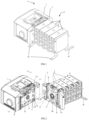
- FIG. 1 is a perspective view of a switching apparatus 9 according to implementations of the present disclosure
- FIG. 2 is an exploded view of a switching apparatus 9 according to implementations of the present disclosure.
- the switching apparatus 9 includes an operating mechanism 1 and a switching component 8.
- the operating mechanism 1 is used to control the switching state of the switching component 8 with any one of the power supplies.
- the switching state means the connection state of the power supplies with the load circuit.
- the two position transfer switch there are two switching state, one of which is the connection of the main power supplies with the load circuit and another is the connection of the standby power supplies with the load circuit.
- the three position transfer switch in addition to the above two switching state, there is an off state which means no power supply is connected to the load circuit and the load circuit is in a power-off state.
- the operating mechanism 1 and the switching component 8 include a separate main shaft respectively.
- the main shaft of the switching component 8 is called the first main shaft 5 and the main shaft of the operating mechanism 1 is called the second main shaft 4.
- the second main shaft 4 is used to actuate the first main shaft 5 to rotate.
- the switching component 8 can selectively connect and disconnect one of the power supplies to at least one circuit.
- the switching component 8 and the operating mechanism 1 further include cooperating interfaces.
- the interface of the switching component 8 is called a first interface
- the interface of the operating mechanism 1 is called a second interface.
- the second main shaft 4 can be detached from the first main shaft.
- the engagement of the first and second interface includes positioning, locking, fastening and electrical connection between the first and second interfaces.
- the above mentioned structure of the operating mechanism 1 and the switching component 8 allows the operating mechanism 1 to be individually detachably coupled to the switching component 8 to form the switching apparatus 9. This facilitates maintenance and therefore reduces the cost of maintenance.
- the switching component 8 may be fixed to a plate or wall via fastening brackets 81 during normal use.
- the fastening brackets 81 may be fixed on the housing of the switching component 8 via a bolt or the like.
- the fastening brackets 81 may be integrated with the housing of the switching component 8.
- the switching component 8 may be fixed to the plate or the wall in various ways. For example, a bolt may be passed through a hole of each of fastening brackets 81 and screwed into the plate or the wall to fix the switching component 8 thereon. In some implementations, the switching component 8 may be suspended on the plate or the wall by a protrusion on the wall, such as a nail, through the hole of the fastening bracket 81.
- the operating mechanism 1 may be detachably coupled to the switching component 8 and thus the combination of the operating mechanism 1 and the switching component 8, i.e., the switching apparatus 9, may be fixed on the plate or the wall.
- there are at least 4 fastening brackets 81 which are respectively located at the lower corners or at any other suitable positions of the switching component 8.
- the operating mechanism 1 itself further has fastening brackets (not shown).
- the operating mechanism 1 may be further fixed to the plate or the wall via its fastening brackets while being detachably coupled to the switching component 8.
- the fastening brackets of the operating mechanism 1 may be located at all the lower corners of the operating mechanism 1 or only at the lower corners away from the switching component 8.
- the switching apparatus 9 may be a power supply transfer switch and include an indicator 2 and a plurality of poles 3 adapted to selectively connect and disconnect one of at least two power supplies to a load circuit.
- the indicator 2 may be located on one side of the plurality of the poles 3 and can indicate the switching state.
- the first interface may be provided on the indicator 2 and the first main shaft 5 may pass through the indicator 2 to another side of the plurality of poles 3.
- the first main shaft 5 itself may use separate structures comprising separate main shafts like the first and the second main shafts. That is, there are separate main shafts in the indicator 2 and the plurality of poles 3 or between any one of the plurality of poles 3. Accordingly, the indicators 2 and any one of the plurality of poles 3 can be individually maintained or replaced in the event of a fault. This further makes it easy to maintain any one part of the switching apparatus 9.
- the above structure allows the operating mechanism 1 to be detached from the switching component 8 while keeping the switching state of the switching component 8 unchanged. That is, the operating mechanism 1 can be removed in any switching state of the switching component 8, even in the state of one of at least two power supplies and the load circuit being connected.
- a locking member 6 is provided in the first interface, as shown in FIGs. 3A to 4B .
- the locking member 6 includes a locking pin 61 which can be inserted in one of the at least one locking slot 51 to limit the rotation of the first main shaft 5.
- the locking member 6 may be located in a cavity of the indicator 2 and can slide between two positions, which refer to a release position and a locking position for ease of description.
- the locking pin 61 is located outside one of the at least one locking slot 51. As shown in FIGs. 3A and 4B , in the locking position, the locking pin 61 is located inside one of the locking slots 51.
- the locking member 6 includes an operating member 62 having a slot 66. A tool (not shown) can be inserted into the slot 66 to drive the operating member 62 to move from the inside of the housing of the indicator 2 to the outside, such that the locking member 6 is driven to move from the release position to the locking position.
- the locking slot 51 and the locking pin 61 may use other forms of mutual cooperation, such as the gears, or the like.
- a locking hole 65 is provided on the operating member 62, which is used for a locker (not shown) to pass through to hold the locking member 6 in the locking position. It should be understood that the locking member 62 may be held in the locking position in other ways, for example, by friction, snap connection, or the like.
- the outer end of the operating member 62 is substantially flush with the outer surface of the indicator 2 in the release position, as shown in FIG. 3B .
- a recess may be provided at the position of the outer surface of the indicator 2 adjacent to the operating member 62 to facilitate the insertion of the tool into the locking hole 65.
- an elastic element 63 such as a spring, is provided to be connected to the locking member 6.
- an end of the elastic element 63 may be fixed on the housing of the indicator 2, and another end may be connected to a hook 67 of the locking member 6 for driving the locking member 6 to move from the locking position to the release positions in response to the release of the operating member 62, i.e., the release of the engagement between the slot 66 and the tool.
- FIG. 5 is an exploded view of a switching apparatus 9 according to implementations of the present disclosure
- FIG. 6 shows partially cross-sectional views of the switching apparatus 9 according to an implementation of the present disclosure.
- at least a fastening stud 7 is provided to fix the operating mechanism 1 to the switching component 8 in position.
- fastening lugs 11 each having a through-hole and corresponding receiving slots 21 for receiving the fastening lugs 11 may be arranged on the first and second interfaces respectively.
- the fastening studs 7 may be inserted into the through-hole and screwed into the switching component 8 from an operating hole 24.
- the operating mechanism 1 may be connected to the switching component 8 compactly.
- the fastening studs 7 may be screwed in or out only from the operating hole 24 only when the first main shaft 5 is locked, which will be discussed in detail below.
- the operating mechanism 1 may be connected to the switching component 8 in a more safe way.
- the fastening lugs 11 may include at least an upper fastening lug 111 and at least a lower fastening lug 113.
- the through-hole in the upper fastening lug 111 or in the lower fastening lug 113 may be a threaded hole 112 which may be engaged with a threaded section on the fastening stud 7.
- the through-holes in the upper and lower fastening lugs 111, 113 may both be threaded holes.
- a slider 22 which may cover the operating hole 24 is provided in the first interface, preferably, in the indicator 2, as shown in FIGs. 7A to 9B .
- the slider 22 may be coupled to the locking member 6.
- the slider 22 may be driven by the locking member 6 from a covering position in which the operating hole 24 is covered and to an opening position in which the operating hole 24 is opened.
- the slider 22 may be driven from the covering position to the opening position, as shown in FIG. 8B .
- the operating hole 24 is open, which allows a tool to insert in the operating hole 24 to screw the fastening stud 7 out.
- the operating mechanism 1 may be detached from the switching component 8. It should be understood that the operating hole 24 keeps open during the maintenance. After the maintenance, the fastening lug 11 may be inserted back into the receiving slot 21 again, and then the fastening stud 7 may be inserted into the through-hole of the fastening lug 11 from the operating hole 24.
- the slider 22 Before the fastening stud 7 being screwed into the switching component 8, at least a part of the fastening stud 7 protrudes from the switching component 8. As a result, the slider 22 cannot move from the opening position back to the covering position even the locker is not used in the locking hole 65. This is because the slider 22 is obstructed by the at least part of the fastening stud 7. After the fastening stud 7 being screwed into the switching component 8 completely and in the case of the tool being released from the slot 66 and the locker being removed from the locking hole 65, the slider 22 may be driven by the locking member 6 from the opening position to the covering position, as shown in FIG. 9A .
- the slider 22 may be driven by the locking member 6 by the following means. Specifically, as shown in FIGs. 7A and 7B , an oblique slot 64 may be provided on the locking member 6 and a guiding pin 23 which may be inserted in the oblique slot 64 is arranged on the slider 22. As a result, the movement of the locking member 6 may drive the slider 22 to slide via the guiding pin 23.
- the moving direction of the locking member 6 between the locking position and the release position which is referred to as the first direction for ease of description, is perpendicular to the sliding direction of the slider 22 between the opening position and the covering position, which is referred to as the second direction for ease of description.
- the oblique slot 64 may be oblique relative to the first and second directions.
- the position of the oblique slot 64 and the guiding pin 23 may be interchanged. That is, the oblique slot 64 may be provided on the slider 22 and the guiding pin 23 may be arranged on the locking member alternatively. Furthermore, in some implementations, the oblique slot 64 and the guiding pin 23 may use other forms of mutual cooperation, such as the link mechanism, or the like.
- the locking member 6 may be preferably used both as a locking means to lock the first main shaft 5 in position and as a driving means to drive the slider 22. It should be understood that in some implementations, the locking member 6 may be used as any one of the locking means and the driving means. For example, the locking member 6 may be used as locking means to lock the first main shaft 5, whereas the slider 22 may be driven by other means, and vice versa.
- a plurality of protrusions 41 may be provided on the outer circumference of the second main shaft 4.
- a plurality of notches 53 may be arranged on the inner circumference of the first main shaft 5.
- each of the plurality of protrusions 41 may be inserted into one of the plurality of the notches 53 to transmit the rotation of the second main shaft 4 to the first main shaft 5. It should be understood that the protrusions 41 and notches 53 may be distributed on the circumference evenly or unevenly.
- a mis-displaced structure in order to prevent mistake insertion that the second main shaft 4 is not inserted into the first main shaft at the same rotation position as being detached from the first main shaft 5, a mis-displaced structure may be used.
- an alignment shaft 52 may be provide eccentrically inside the first main shaft 5 and parallel to the first main shaft 5.
- two convex hulls 42 may extend radially and inwardly from the inner circumference of the second main shaft 4 and face to each other.
- each of the two convex hulls 42 from the inner circumference of the second main shaft 4 may be larger than the minimum distance between the alignment shaft 52 and the inner circumference of the second main shaft 4.
- the convex hull 42 may have a substantially semicircular cross section, and its span in the inner circumferential direction is preferably no less than 45 degree. It should be understood that the convex hull 42 may have other shape, such as the wedge shape, or the like. Furthermore, the convex hull 42 and the alignment shaft 52 may be hollow or solid.
- the second main shaft 4 cannot be inserted back into the first main shaft 5 due to the interference and the second main shaft 4 only be inserted into the first main shaft 5 at the same rotation position as being detached from the first main shaft 5. Accordingly, the mistake insertion may be prevented.
- position means are provided on the first and second interfaces to ensure the positioning of the first and second interfaces.
- a first positioning means 26 may be arranged on the first interface and a corresponding second positioning means 12 may be arranged on the second interface. Accordingly, the first positioning means 26 may be coupled with the second positioning means 12 to position the second interface relative to the first interface.
- the first positioning means 26 may be a protrusion protruding from the first interface and the second positioning means 12 is a hole to receive the protrusion, as shown in FIGs. 2 and 5 . It should be understood that the protrusion and the hole may be interchanged.
- first and second interfaces there are electrical connection interfaces provided on the first and second interfaces to electrically connect the operating mechanism 1 with the switching component 8.
- a first electrical connection interface 27 such as a female connector
- a second electrical connection interface 13 such as a male connecter which may be inserted into the female connector
- the electrical connection may be established easily. It should be understood that the male and female connecters may be interchanged.
Landscapes
- Physics & Mathematics (AREA)
- Electromagnetism (AREA)
- Business, Economics & Management (AREA)
- Emergency Management (AREA)
- Engineering & Computer Science (AREA)
- Power Engineering (AREA)
- Switch Cases, Indication, And Locking (AREA)
Description
- Switching apparatus being widely used in industrial and home applications is well-known. Electrical automatic transfer switch is a kind of switching apparatus, which is commonly used in power distribution system for detecting and monitoring the power quality and transferring supply between main power supply and standby power supply. The automatic transfer switch typically includes an operating mechanism, an indicator and a plurality of poles. Generally, the plurality of poles are coupled to the main power supply and the standby power supply, and the operating mechanism is used to selectively connect and disconnect one of the power supplies to the load circuit, which is indicated by the indicator. Furthermore, the type of the automatic transfer switch at least includes two-position automatic transfer switch and three-position automatic transfer switch.
- Typically, an integrated main shaft extends from the operating mechanism to the poles through the indicator. As a result, the conventional operating mechanism of the automatic transfer switch cannot be disassembled alone, not to mention disassembly in the case of holding the switching state of the plurality of poles with the normal power supply or standby power supply. Examples of known switching apparatuses are described in publications
DE 20 2009 001387 U1 ,US 7 863 530 B2 ,CN 102 810 417 B ,CN 100 413 005 C andCN 105 336 519 A . The switching apparatus as disclosed in the publicationDE 20 2009 001387 U1 corresponds to the preamble of claim 1. - Implementations of the subject matter described herein provide a solution for providing an operating mechanism being detached from a switching component without change the switching state of the switching component.
- In accordance with the invention, a switching apparatus as set forth in claim 1 is provided. Further embodiments are inter alia disclosed in the dependent claims. In particular the switching apparatus includes a switching component comprising a first main shaft and adapted to selectively connect or disconnect at least one circuit in response to a rotation of the first main shaft; and an operating mechanism comprising a second main shaft for actuating the rotation of the first main shaft; wherein the switching component further includes a first interface, the operating mechanism further includes a second interface, and the second main shaft can be detachably coupled to the first main shaft in response to an engagement of the first interface and the second interface.
- Different from the conventional apparatus, the switching apparatus having the above-described structure allows the operating mechanism can be detached from the switch module individually while keeping the switching state of the switching component unchanged. This makes the switching apparatus more easy to be maintained, and thus reduces the maintenance cost. Furthermore, the above-described structure results in the maintenance may be performed without switching off the power supplies, which does not affect people's daily lives.
- According to the invention, a locking member is arranged inside the first interface for locking the first main shaft in a rotation position corresponding to a switching state of the switching component.
- The first main shaft includes at least one locking slot arranged on its circumference, and the locking member includes a locking pin operable to be inserted into one of the at least one locking slot to limit the rotation of the first main shaft.
- With the above arrangement of the first main shaft and the locking member, the first main shaft may be locked in a certain position during the maintenance. This ensures that the operating mechanism may be detached from the switching component without changing the switching state of the switching component.
- According to the invention, the locking member includes an operating member and operable to move from a release position to a locking position, in the release position, the locking pin is located outside one of the at least one locking slot, and in the locking position, the locking pin is located inside one of the at least one locking slot.
- According to the invention, an elastic element is coupled to the locking member for driving the locking member to move from the locking position to the release position in response to a release of the operating member.
- In some implementations, the switching apparatus further includes fastening lugs arranged on the first interface and having a through-hole; receiving slots arranged on the second interface for receiving the fastening lugs; and at least one fastening stud adapted to be inserted in the through-hole on the fastening lugs and screwed into the switching component from an operating hole on the switching component.
- With the above structure, the operating mechanism may be coupled to the switching component in a compact and safe way.
- In some implementations, a slider is arranged inside the first interface and coupled to the locking member, the slider can be driven by the locking member to cover or open the operating hole.
- In some implementations, a first direction of movement of the locking member is perpendicular to a second direction of the slider, and an oblique slot is arranged on one of the slider and the locking member, the oblique slot being oblique relative to both the first and second directions, and a guiding pin is arranged on the other one of the of the slider and the locking member, the guiding pin engaging with the oblique slot to allow the locking member to drive the slider.
- With the above arrangement of the slider and the locking member, in response to the movement of the locking member from the release position to the locking position, the slider may slide from a covering position to an opening position. That is, the fastening stud can be operated merely when the locking member is in the locking position. As a result, the maintenance of the switching apparatus is more secure.
- In some implementations, the operating member includes a locking hole for allowing a locker to pass through to hold the locking member in the locking position.
- According to the invention, the operating member includes a slot for engaging with a tool to pass through to move the locking member from the release position to the locking position.
- In some implementations, the second main shaft includes a plurality of protrusions arranged on an outer circumference; and the first main shaft includes a plurality of notches arranged on an inner circumference for receiving the plurality of protrusions to transmit a rotation of the second main shaft to the first main shaft.
- In some implementations, the first main shaft further includes an alignment shaft arranged parallel to and eccentrically inside the first main shaft, and the second main shaft further includes convex hulls extending radially and inwardly from inner circumference of the second main shaft; wherein an height of one of the convex hulls from the inner circumference of the second main shaft exceeds a minimum distance between the alignment shaft and the inner circumference of the second main shaft, such that the second main shaft is adapted to be inserted into the first main shaft only at a same rotation position as being detached from the first main shaft.
- In some implementations, the fastening lugs include at least one upper fastening lug and at least one lower fastening lug, and the through-hole in at least one of the upper fastening lug and the lower fastening lug is a threaded hole to be engaged with a threaded section on the fastening stud.
- With the above arrangement of the first and second main shafts, the mistake insertion of the second main shaft that the rotating position is not same as being detached from the first main shaft is prevented. This improves the security of the switching apparatus effectively.
- In some implementations, the first interface includes a first positioning means, and the second interface includes a second positioning means coupled with the first positioning means to position the second interface relative to the first interface.
- In some implementations, the first interface includes a first electrical connection interface, and the second interface includes a second electrical connection interface coupled with the first electrical connection interface to provide electrical connection between the operating mechanism and the switching component.
- In some implementations, the switching component includes an indicator for indicating a switching state of the switching component, and wherein the first interface is arranged on the indicator, and the first main shaft passes through the indicator.
- In some implementations, the switching apparatus is a power supply transfer switch, and the switching component is operable to selectively couple one of at least two power supplies to a load circuit.
- It is to be understood that the Summary is not intended to identify key or essential features of implementations of the subject matter described herein, nor is it intended to be used to limit the scope of the subject matter described herein. Other features of the subject matter described herein will become easily comprehensible through the description below.
- The above and other objectives, features and advantages of the subject matter described herein will become more apparent through more detailed depiction of example implementations of the subject matter described herein in conjunction with the accompanying drawings, wherein in the example implementations of the subject matter described herein, same reference numerals usually represent same components.
-
FIG. 1 is a perspective view of a switching apparatus according to implementations of the present disclosure; -
FIG. 2 is an exploded view of a switching apparatus according to implementations of the present disclosure; -
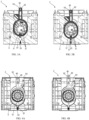
FIGs. 3A-3B show cross-sectional views of the indicator according to implementations of the present disclosure, whereFIG. 3A shows the locking member being in the locking position andFIG. 3B shows the locking member being in the release position; -
FIGs. 4A-4B show side views of the indicator according to implementations of the present disclosure, whereFIG. 4A shows the locking member being in the release position andFIG. 4B shows the locking member being in the locking position; -
FIG. 5 is an exploded view of a switching apparatus according to implementations of the present disclosure, where the fastening studs are removed from the indicator; -
FIG. 6 shows partially cross-sectional views of the switching apparatus according to an implementation of the present disclosure; -
FIGs. 7A-8B show side views of the indicator according to implementations of the present disclosure, whereFIGs. 7A and 8A show the locking member being in the release position andFIGs. 7B and 8B show the locking member being in the locking position; -
FIGs. 9A-9B show perspective view of the indicator according to an implementation of the present disclosure; whereFIG. 9A shows the locking member being in the release position andFIG. 9B shows the locking member being in the locking position; and -
FIGs. 10A-10B show cross-sectional views of the switching apparatus according to an implementation of the present disclosure; whereFIG. 10B is a partially enlarged view of the first and second main shafts showing inFIG. 10A ; - Throughout the drawings, the same or similar reference symbols are used to indicate the same or similar elements.
- The subject matter described herein will now be discussed with reference to several example implementations. It should be understood these implementations are discussed only for the purpose of enabling those skilled persons in the art to better understand and thus implement the subject matter described herein, rather than suggesting any limitations on the scope of the subject matter.
- As used herein, the term "includes" and its variants are to be read as open terms that mean "includes, but is not limited to." The term "based on" is to be read as "based at least in part on." The term "one implementation" and "an implementation" are to be read as "at least one implementation." The term "another implementation" is to be read as "at least one other implementation." The terms "first," "second," and the like may refer to different or same objects. Other definitions, explicit and implicit, may be included below. A definition of a term is consistent throughout the description unless the context clearly indicates otherwise.
- In some conventional designs, the switching apparatus includes an integrated shaft extending from the operating mechanism to the poles. This structure determines that the operating mechanism cannot be disassembled alone. Accordingly, this brings a lot of inconvenience to the maintenance. For example, if only a small problem occurs in the operating mechanism, a cutting off of the power supply is required and the entire switching apparatus should be completely removed, which also results in increased maintenance costs.
-
FIG. 1 is a perspective view of aswitching apparatus 9 according to implementations of the present disclosure andFIG. 2 is an exploded view of aswitching apparatus 9 according to implementations of the present disclosure. Generally, theswitching apparatus 9 according to implementations of the present disclosure includes an operating mechanism 1 and a switching component 8. The operating mechanism 1 is used to control the switching state of the switching component 8 with any one of the power supplies. Specifically, the switching state means the connection state of the power supplies with the load circuit. For example, for the two position transfer switch, there are two switching state, one of which is the connection of the main power supplies with the load circuit and another is the connection of the standby power supplies with the load circuit. Furthermore, for the three position transfer switch, in addition to the above two switching state, there is an off state which means no power supply is connected to the load circuit and the load circuit is in a power-off state. - Different from the conventional switching apparatus, the operating mechanism 1 and the switching component 8 include a separate main shaft respectively. For ease of description, the main shaft of the switching component 8 is called the first
main shaft 5 and the main shaft of the operating mechanism 1 is called the secondmain shaft 4. The secondmain shaft 4 is used to actuate the firstmain shaft 5 to rotate. In response to the rotation of the firstmain shaft 5, the switching component 8 can selectively connect and disconnect one of the power supplies to at least one circuit. - Furthermore, the switching component 8 and the operating mechanism 1 further include cooperating interfaces. For ease of description, the interface of the switching component 8 is called a first interface, and the interface of the operating mechanism 1 is called a second interface. In response to the engagement of the first and second interface, the second
main shaft 4 can be detached from the first main shaft. The engagement of the first and second interface includes positioning, locking, fastening and electrical connection between the first and second interfaces. - Accordingly, the above mentioned structure of the operating mechanism 1 and the switching component 8 allows the operating mechanism 1 to be individually detachably coupled to the switching component 8 to form the
switching apparatus 9. This facilitates maintenance and therefore reduces the cost of maintenance. - In some implementations, the switching component 8 may be fixed to a plate or wall via
fastening brackets 81 during normal use. Thefastening brackets 81 may be fixed on the housing of the switching component 8 via a bolt or the like. In some implementations, thefastening brackets 81 may be integrated with the housing of the switching component 8. - The switching component 8 may be fixed to the plate or the wall in various ways. For example, a bolt may be passed through a hole of each of
fastening brackets 81 and screwed into the plate or the wall to fix the switching component 8 thereon. In some implementations, the switching component 8 may be suspended on the plate or the wall by a protrusion on the wall, such as a nail, through the hole of thefastening bracket 81. - After that, the operating mechanism 1 may be detachably coupled to the switching component 8 and thus the combination of the operating mechanism 1 and the switching component 8, i.e., the
switching apparatus 9, may be fixed on the plate or the wall. In some implementations, there are at least 4fastening brackets 81 which are respectively located at the lower corners or at any other suitable positions of the switching component 8. - In some implementations, the operating mechanism 1 itself further has fastening brackets (not shown). For example, in a case that the operating mechanism 1 is too heavy to be fixed by the fastening means between the operating mechanism 1 and the switching component 8, the operating mechanism 1 may be further fixed to the plate or the wall via its fastening brackets while being detachably coupled to the switching component 8. In some implementations, the fastening brackets of the operating mechanism 1 may be located at all the lower corners of the operating mechanism 1 or only at the lower corners away from the switching component 8.
- As shown in
FIG. 1 , in some implementations, theswitching apparatus 9 according to the present disclosure may be a power supply transfer switch and include anindicator 2 and a plurality ofpoles 3 adapted to selectively connect and disconnect one of at least two power supplies to a load circuit. Theindicator 2 may be located on one side of the plurality of thepoles 3 and can indicate the switching state. In some implementations, the first interface may be provided on theindicator 2 and the firstmain shaft 5 may pass through theindicator 2 to another side of the plurality ofpoles 3. - In some implementations, the first
main shaft 5 itself may use separate structures comprising separate main shafts like the first and the second main shafts. That is, there are separate main shafts in theindicator 2 and the plurality ofpoles 3 or between any one of the plurality ofpoles 3. Accordingly, theindicators 2 and any one of the plurality ofpoles 3 can be individually maintained or replaced in the event of a fault. This further makes it easy to maintain any one part of theswitching apparatus 9. - Furthermore, the above structure allows the operating mechanism 1 to be detached from the switching component 8 while keeping the switching state of the switching component 8 unchanged. That is, the operating mechanism 1 can be removed in any switching state of the switching component 8, even in the state of one of at least two power supplies and the load circuit being connected.
- In order to prevent an undesired rotation of the first
main shaft 5 in the case of thesecond shaft 4 being detached from the firstmain shaft 5, a lockingmember 6 is provided in the first interface, as shown inFIGs. 3A to 4B . This ensures that the firstmain shaft 5 may keep in a rotation position corresponding to the switching sate of the switching component 8. Therefore, when the operating mechanism 1 is assembled to the switching component 8 again, the lockingmember 6 ensures the rotation position of the secondmain shaft 4 being same as being detached from the firstmain shaft 5. Thus, the occurrence of misplaced assembly of the first andsecond shafts - As shown in
FIGs. 3A and 3B , at least onelocking slot 51 is provided on the circumference of the firstmain shaft 5. Correspondingly, the lockingmember 6 includes a lockingpin 61 which can be inserted in one of the at least onelocking slot 51 to limit the rotation of the firstmain shaft 5. In some implementations, the lockingmember 6 may be located in a cavity of theindicator 2 and can slide between two positions, which refer to a release position and a locking position for ease of description. - Specifically, in the release position, as shown in
FIGs. 3B and 4A , the lockingpin 61 is located outside one of the at least onelocking slot 51. As shown inFIGs. 3A and 4B , in the locking position, the lockingpin 61 is located inside one of the lockingslots 51. The lockingmember 6 includes an operatingmember 62 having aslot 66. A tool (not shown) can be inserted into theslot 66 to drive the operatingmember 62 to move from the inside of the housing of theindicator 2 to the outside, such that the lockingmember 6 is driven to move from the release position to the locking position. Furthermore, in some implementations, the lockingslot 51 and the lockingpin 61 may use other forms of mutual cooperation, such as the gears, or the like. - As shown in
FIG. 3A , in some implementations, a lockinghole 65 is provided on the operatingmember 62, which is used for a locker (not shown) to pass through to hold the lockingmember 6 in the locking position. It should be understood that the lockingmember 62 may be held in the locking position in other ways, for example, by friction, snap connection, or the like. - In some implementations, the outer end of the operating
member 62 is substantially flush with the outer surface of theindicator 2 in the release position, as shown inFIG. 3B . A recess may be provided at the position of the outer surface of theindicator 2 adjacent to the operatingmember 62 to facilitate the insertion of the tool into the lockinghole 65. - As shown in
FIGs. 3A and 3B , anelastic element 63, such as a spring, is provided to be connected to the lockingmember 6. In some implementations, an end of theelastic element 63 may be fixed on the housing of theindicator 2, and another end may be connected to ahook 67 of the lockingmember 6 for driving the lockingmember 6 to move from the locking position to the release positions in response to the release of the operatingmember 62, i.e., the release of the engagement between theslot 66 and the tool. -
FIG. 5 is an exploded view of aswitching apparatus 9 according to implementations of the present disclosure; andFIG. 6 shows partially cross-sectional views of theswitching apparatus 9 according to an implementation of the present disclosure. As shown inFIGs. 2 ,5 and 6 , in some implementations, at least afastening stud 7 is provided to fix the operating mechanism 1 to the switching component 8 in position. To this end, in some implementations, fastening lugs 11 each having a through-hole and corresponding receivingslots 21 for receiving the fastening lugs 11 may be arranged on the first and second interfaces respectively. - As shown in
FIG. 6 , thefastening studs 7 may be inserted into the through-hole and screwed into the switching component 8 from anoperating hole 24. In this way, the operating mechanism 1 may be connected to the switching component 8 compactly. Furthermore, thefastening studs 7 may be screwed in or out only from the operatinghole 24 only when the firstmain shaft 5 is locked, which will be discussed in detail below. Thus, the operating mechanism 1 may be connected to the switching component 8 in a more safe way. - In some implementations, the fastening lugs 11 may include at least an
upper fastening lug 111 and at least alower fastening lug 113. The through-hole in theupper fastening lug 111 or in thelower fastening lug 113 may be a threadedhole 112 which may be engaged with a threaded section on thefastening stud 7. In some implementations, the through-holes in the upper and lower fastening lugs 111, 113 may both be threaded holes. - In order to prevent the
fastening studs 7 from being erroneously removed during the normal use of theswitching apparatus 9, aslider 22 which may cover theoperating hole 24 is provided in the first interface, preferably, in theindicator 2, as shown inFIGs. 7A to 9B . In some implementations, theslider 22 may be coupled to the lockingmember 6. As a result, theslider 22 may be driven by the lockingmember 6 from a covering position in which theoperating hole 24 is covered and to an opening position in which theoperating hole 24 is opened. - Specifically, in the case of the locking
member 6 moving from the release position to the locking position, theslider 22 may be driven from the covering position to the opening position, as shown inFIG. 8B . Accordingly, the operatinghole 24 is open, which allows a tool to insert in theoperating hole 24 to screw thefastening stud 7 out. Thereby the operating mechanism 1 may be detached from the switching component 8. It should be understood that the operatinghole 24 keeps open during the maintenance. After the maintenance, thefastening lug 11 may be inserted back into the receivingslot 21 again, and then thefastening stud 7 may be inserted into the through-hole of thefastening lug 11 from the operatinghole 24. - Before the
fastening stud 7 being screwed into the switching component 8, at least a part of thefastening stud 7 protrudes from the switching component 8. As a result, theslider 22 cannot move from the opening position back to the covering position even the locker is not used in the lockinghole 65. This is because theslider 22 is obstructed by the at least part of thefastening stud 7. After thefastening stud 7 being screwed into the switching component 8 completely and in the case of the tool being released from theslot 66 and the locker being removed from the lockinghole 65, theslider 22 may be driven by the lockingmember 6 from the opening position to the covering position, as shown inFIG. 9A . - In some implementations, the
slider 22 may be driven by the lockingmember 6 by the following means. Specifically, as shown inFIGs. 7A and 7B , anoblique slot 64 may be provided on the lockingmember 6 and a guidingpin 23 which may be inserted in theoblique slot 64 is arranged on theslider 22. As a result, the movement of the lockingmember 6 may drive theslider 22 to slide via the guidingpin 23. In some implementations, the moving direction of the lockingmember 6 between the locking position and the release position, which is referred to as the first direction for ease of description, is perpendicular to the sliding direction of theslider 22 between the opening position and the covering position, which is referred to as the second direction for ease of description. Correspondingly, theoblique slot 64 may be oblique relative to the first and second directions. - It should be understood that the position of the
oblique slot 64 and the guidingpin 23 may be interchanged. That is, theoblique slot 64 may be provided on theslider 22 and the guidingpin 23 may be arranged on the locking member alternatively. Furthermore, in some implementations, theoblique slot 64 and the guidingpin 23 may use other forms of mutual cooperation, such as the link mechanism, or the like. - It can be seen from the above that in some implementations, the locking
member 6 may be preferably used both as a locking means to lock the firstmain shaft 5 in position and as a driving means to drive theslider 22. It should be understood that in some implementations, the lockingmember 6 may be used as any one of the locking means and the driving means. For example, the lockingmember 6 may be used as locking means to lock the firstmain shaft 5, whereas theslider 22 may be driven by other means, and vice versa. - After the operating mechanism 1 is fitted on the switching component 8, there are many ways in which the first and second main shafts couple with each other. In some implementations, as shown in
FIGs. 10A and 10B , a plurality ofprotrusions 41 may be provided on the outer circumference of the secondmain shaft 4. Correspondingly, a plurality of notches 53 may be arranged on the inner circumference of the firstmain shaft 5. As a result, each of the plurality ofprotrusions 41 may be inserted into one of the plurality of the notches 53 to transmit the rotation of the secondmain shaft 4 to the firstmain shaft 5. It should be understood that theprotrusions 41 and notches 53 may be distributed on the circumference evenly or unevenly. - It should be understood that the above implementations are the exemplary implementations, and other appropriate means may be used to transmit the rotation of the second
main shaft 4. For example, the key and groove fit, the gears, or the like can be used alternatively. - In some implementations, in order to prevent mistake insertion that the second
main shaft 4 is not inserted into the first main shaft at the same rotation position as being detached from the firstmain shaft 5, a mis-displaced structure may be used. Preferably, as shown inFIG. 10B , analignment shaft 52 may be provide eccentrically inside the firstmain shaft 5 and parallel to the firstmain shaft 5. Correspondingly, twoconvex hulls 42 may extend radially and inwardly from the inner circumference of the secondmain shaft 4 and face to each other. - The height of each of the two
convex hulls 42 from the inner circumference of the secondmain shaft 4 may be larger than the minimum distance between thealignment shaft 52 and the inner circumference of the secondmain shaft 4. In some implementations, theconvex hull 42 may have a substantially semicircular cross section, and its span in the inner circumferential direction is preferably no less than 45 degree. It should be understood that theconvex hull 42 may have other shape, such as the wedge shape, or the like. Furthermore, theconvex hull 42 and thealignment shaft 52 may be hollow or solid. - In this situation, it is assumed that the positions of the first and second
main shafts FIG. 10A are in a state of the load circuit being connected to the main power supply, and the operating mechanism 1 is detached from the switching component 8 in this state. If the accidental rotation of the secondmain shaft 4 occurs during the maintenance, for example, the secondmain shaft 4 rotates accidentally from the position corresponding to the main power supply to another position corresponding to the standby power supply or to the off position, the twoconvex hull 42 rotates to the position interfering with the alignment shaft correspondingly. - As a result, the second
main shaft 4 cannot be inserted back into the firstmain shaft 5 due to the interference and the secondmain shaft 4 only be inserted into the firstmain shaft 5 at the same rotation position as being detached from the firstmain shaft 5. Accordingly, the mistake insertion may be prevented. - Referring back to
FIGs. 2 and5 , in some implementations, position means are provided on the first and second interfaces to ensure the positioning of the first and second interfaces. Preferably, a first positioning means 26 may be arranged on the first interface and a corresponding second positioning means 12 may be arranged on the second interface. Accordingly, the first positioning means 26 may be coupled with the second positioning means 12 to position the second interface relative to the first interface. In some implementations, the first positioning means 26 may be a protrusion protruding from the first interface and the second positioning means 12 is a hole to receive the protrusion, as shown inFIGs. 2 and5 . It should be understood that the protrusion and the hole may be interchanged. - In some implementations, there are electrical connection interfaces provided on the first and second interfaces to electrically connect the operating mechanism 1 with the switching component 8. Preferably, a first
electrical connection interface 27, such as a female connector, may be arranged on the first interface, and a secondelectrical connection interface 13, such as a male connecter which may be inserted into the female connector, may be arranged on the second interface. As a result, the electrical connection may be established easily. It should be understood that the male and female connecters may be interchanged.
Claims (10)
- A switching apparatus (9) comprising:a switching component (8) comprising a first main shaft (5) and adapted to selectively connect or disconnect at least one circuit in response to a rotation of the first main shaft (5); andan operating mechanism (1) comprising a second main shaft (4) for actuating the rotation of the first main shaft (5);wherein the switching component (8) further comprises a first interface, the operating mechanism (1) further comprises a second interface, and the second main shaft (4) can be detachably coupled to the first main shaft (5) in response to an engagement of the first interface and the second interface,characterized in that a locking member (6) is arranged inside the first interface for locking the first main shaft (5) in a rotation position corresponding to a switching state of the switching component (8),wherein the first main shaft (5) comprises at least one locking slot (51) arranged on its circumference, andthe locking member (6) comprises a locking pin (61) operable to be inserted into one of the at least one locking slot (51) to limit the rotation of the first main shaft (5),wherein the locking member (6) comprises an operating member (62) and operable to move from a release position to a locking position,in the release position, the locking pin (61) is located outside one of the at least one locking slot (51), andin the locking position, the locking pin (61) is located inside one of the at least one locking slot (51),wherein an elastic element (63) is coupled to the locking member (6) for driving the locking member (6) to move from the locking position to the release position in response to a release of the operating member (62),wherein the operating member (62) comprises a slot (66) for engaging with a tool to pass through to move the locking member (6) from the release position to the locking position.
- The switching apparatus (9) of claim 1, further comprising:fastening lugs (11) arranged on the second interface and having a through-hole;receiving slots (21) arranged on the first interface for receiving the fastening lugs (11); andat least one fastening stud (7) adapted to be inserted in the through-hole on the fastening lugs (11) and screwed into the switching component (8) from an operating hole (24) on the switching component (8).
- The switching apparatus (9) of claim 2, wherein
a slider (22) is arranged inside the first interface and coupled to the locking member (6), the slider (22) can be driven by the locking member (6) to cover or open the operating hole (24). - The switching apparatus (9) of claim 3, whereina first direction of movement of the locking member (6) is perpendicular to a second direction of the slider (22), andan oblique slot (64) is arranged on one of the slider (22) and the locking member (6), the oblique slot (64) being oblique relative to both the first and second directions, anda guiding pin (23) is arranged on the other one of the of the slider (22) and the locking member (6), the guiding pin (23) engaging with the oblique slot (64) to allow the locking member (6) to drive the slider (22).
- The switching apparatus (9) of claim 1, wherein the operating member (62) comprises a locking hole (65) for allowing a locker to pass through to hold the locking member (6) in the locking position.
- The switching apparatus (9) of claim 1, whereinthe second main shaft (4) comprises a plurality of protrusions (41) arranged on an outer circumference; andthe first main shaft (5) comprises a plurality of notches (53) arranged on an inner circumference for receiving the plurality of protrusions (41) to transmit a rotation of the second main shaft (4) to the first main shaft (5).
- The switching apparatus (9) of claim 6, wherein the first main shaft (5) further comprises an alignment shaft (52) arranged parallel to and eccentrically inside the first main shaft (5), andthe second main shaft (4) further comprises convex hulls (42) extending radially and inwardly from inner circumference of the second main shaft (4);wherein an height of one of the convex hulls (42) from the inner circumference of the second main shaft (4) exceeds a minimum distance between the alignment shaft (52) and the inner circumference of the second main shaft (4), such that the second main shaft (4) is adapted to be inserted into the first main shaft (5) only at a same rotation position as being detached from the first main shaft (5).
- The switching apparatus (9) of claim 2, wherein the fastening lugs (11) comprise at least one upper fastening lug (111) and at least one lower fastening lug (113), and the through-hole in at least one of the upper fastening lug (111) and the lower fastening lug (113) is a threaded hole (112) to be engaged with a threaded section (72) on the fastening stud (7).
- The switching apparatus (9) of claim 1, wherein the first interface comprises a first positioning means (26), and
the second interface comprises a second positioning means (12) coupled with the first positioning means (26) to position the second interface relative to the first interface. - The switching apparatus (9) of claim 1, wherein the first interface comprises a first electrical connection interface (27), and
the second interface comprises a second electrical connection interface (13) coupled with the first electrical connection interface (27) to provide electrical connection between the operating mechanism (1) and the switching component (8).
Applications Claiming Priority (2)
| Application Number | Priority Date | Filing Date | Title |
|---|---|---|---|
| CN201710833670.5A CN109509649B (en) | 2017-09-15 | 2017-09-15 | switchgear |
| PCT/CN2018/105827 WO2019052550A1 (en) | 2017-09-15 | 2018-09-14 | SWITCH DEVICE |
Publications (3)
| Publication Number | Publication Date |
|---|---|
| EP3683817A1 EP3683817A1 (en) | 2020-07-22 |
| EP3683817A4 EP3683817A4 (en) | 2021-06-09 |
| EP3683817B1 true EP3683817B1 (en) | 2023-06-28 |
Family
ID=65723492
Family Applications (1)
| Application Number | Title | Priority Date | Filing Date |
|---|---|---|---|
| EP18856378.7A Active EP3683817B1 (en) | 2017-09-15 | 2018-09-14 | Switch device |
Country Status (4)
| Country | Link |
|---|---|
| US (1) | US11322318B2 (en) |
| EP (1) | EP3683817B1 (en) |
| CN (1) | CN109509649B (en) |
| WO (1) | WO2019052550A1 (en) |
Family Cites Families (16)
| Publication number | Priority date | Publication date | Assignee | Title |
|---|---|---|---|---|
| JPH06203690A (en) * | 1992-12-25 | 1994-07-22 | Casio Comput Co Ltd | Release push button |
| US5686709A (en) * | 1995-05-26 | 1997-11-11 | General Electric Company | Modular trip bar assembly for multipole circuit breaker |
| US6084489A (en) * | 1998-09-08 | 2000-07-04 | General Electric Company | Circuit breaker rotary contact assembly locking system |
| FI116864B (en) * | 2004-01-19 | 2006-03-15 | Abb Oy | Modular switchgear |
| FI116866B (en) * | 2004-01-19 | 2006-03-15 | Abb Oy | Brytaranordningsmodul |
| ITBG20050024A1 (en) * | 2005-05-13 | 2006-11-14 | Abb Service Srl | SWITCH INSTALLABLE ACCORDING TO DIFFERENT OPERATIONAL CONFIGURATIONS |
| CN100413005C (en) * | 2006-07-20 | 2008-08-20 | 常熟开关制造有限公司(原常熟开关厂) | Locking device for breaker electric operation mechanism |
| US7889476B2 (en) * | 2006-09-22 | 2011-02-15 | Siemens Industry, Inc. | Electronics for multipole remote operated relay |
| JP2010040325A (en) * | 2008-08-05 | 2010-02-18 | Fuji Electric Fa Components & Systems Co Ltd | Circuit breaker handle lock device |
| DE202009001387U1 (en) * | 2009-02-05 | 2009-06-04 | Fernsteuergeräte Kurt Oelsch GmbH | switching device |
| CN102810417B (en) * | 2011-05-30 | 2014-07-30 | 西门子公司 | Interlocking device for switching mechanism and switching mechanism thereof |
| CN203179728U (en) * | 2013-04-19 | 2013-09-04 | 上海亿盟电气自动化技术有限公司 | Controller display apparatus of automatic transfer switch |
| ITMO20130026U1 (en) * | 2013-08-01 | 2015-02-02 | Abb Technology Ag | INTERLOCK MECHANISM FOR AN ELECTRIC PANEL |
| CN105336519B (en) * | 2014-06-30 | 2018-12-14 | 西门子公司 | The operating unit and switching device group of switching device |
| FR3054925B1 (en) * | 2016-08-02 | 2020-05-15 | Socomec | CONTROL MODULE FOR MODULAR ELECTRICAL SWITCHING APPARATUS AND OBTAINED MODULAR ELECTRICAL SWITCHING APPARATUS |
| CN107068447B (en) * | 2017-04-28 | 2019-11-26 | 爱启(厦门)电气技术有限公司 | A kind of manual and electric module three position mechanism and interlocking |
-
2017
- 2017-09-15 CN CN201710833670.5A patent/CN109509649B/en active Active
-
2018
- 2018-09-14 EP EP18856378.7A patent/EP3683817B1/en active Active
- 2018-09-14 WO PCT/CN2018/105827 patent/WO2019052550A1/en not_active Ceased
-
2020
- 2020-03-16 US US16/820,141 patent/US11322318B2/en active Active
Also Published As
| Publication number | Publication date |
|---|---|
| CN109509649A (en) | 2019-03-22 |
| US11322318B2 (en) | 2022-05-03 |
| US20200279700A1 (en) | 2020-09-03 |
| WO2019052550A1 (en) | 2019-03-21 |
| CN109509649B (en) | 2022-07-05 |
| EP3683817A4 (en) | 2021-06-09 |
| EP3683817A1 (en) | 2020-07-22 |
Similar Documents
| Publication | Publication Date | Title |
|---|---|---|
| JP7688675B2 (en) | Safety switch | |
| EP1531484B1 (en) | Fuse block with integral door sensing rotary disconnect | |
| EP2933812B1 (en) | Shift assembly structure of switch device | |
| US7168968B1 (en) | Plug adapter | |
| EP1641007B1 (en) | Fuse block with integral door sensing rotary disconnect | |
| CN108933338B (en) | Terminal handling device | |
| EP2710684B1 (en) | Electrical connector assembly, and connector for such assembly | |
| RU2485649C2 (en) | Drive system | |
| GB2433547A (en) | Clamping mechanism for securing a surveillance camera housing to a ceiling structure | |
| CN214254887U (en) | Plugs with locking function and connectors including the same | |
| BRPI0609918A2 (en) | electromechanical locking device | |
| US11322318B2 (en) | Switching apparatus | |
| CN110289189A (en) | Lock inserts for cylinder locks | |
| CN211556307U (en) | Pressing plate locking device | |
| CN115483047A (en) | Method for mounting an interlocking module between two contactors and interlocking module | |
| JP2019183542A (en) | Safety switch | |
| CN101183773B (en) | Safety device for embedding installed motor mechanism | |
| KR200442127Y1 (en) | Electric control unit for disconnector with key interlock function | |
| WO1990008396A1 (en) | Safety switch assemblies | |
| CN120183942B (en) | Padlock structure and switch device | |
| CN220065574U (en) | Terminal covers and AC contactors | |
| CN223206141U (en) | Operating handle and motor protector | |
| CN217507752U (en) | Can dismantle connector and supporting unblock spanner safely | |
| CN221127349U (en) | Shell assembly and electronic equipment | |
| JP5001641B2 (en) | Pin tumbler lock and pin tumbler lock device |
Legal Events
| Date | Code | Title | Description |
|---|---|---|---|
| STAA | Information on the status of an ep patent application or granted ep patent |
Free format text: STATUS: THE INTERNATIONAL PUBLICATION HAS BEEN MADE |
|
| PUAI | Public reference made under article 153(3) epc to a published international application that has entered the european phase |
Free format text: ORIGINAL CODE: 0009012 |
|
| STAA | Information on the status of an ep patent application or granted ep patent |
Free format text: STATUS: REQUEST FOR EXAMINATION WAS MADE |
|
| 17P | Request for examination filed |
Effective date: 20200313 |
|
| AK | Designated contracting states |
Kind code of ref document: A1 Designated state(s): AL AT BE BG CH CY CZ DE DK EE ES FI FR GB GR HR HU IE IS IT LI LT LU LV MC MK MT NL NO PL PT RO RS SE SI SK SM TR |
|
| AX | Request for extension of the european patent |
Extension state: BA ME |
|
| DAV | Request for validation of the european patent (deleted) | ||
| DAX | Request for extension of the european patent (deleted) | ||
| A4 | Supplementary search report drawn up and despatched |
Effective date: 20210507 |
|
| RIC1 | Information provided on ipc code assigned before grant |
Ipc: H01H 9/26 20060101AFI20210430BHEP Ipc: H01H 9/24 20060101ALI20210430BHEP Ipc: H01H 9/00 20060101ALN20210430BHEP Ipc: H01H 19/64 20060101ALN20210430BHEP Ipc: H01H 71/10 20060101ALN20210430BHEP |
|
| RIC1 | Information provided on ipc code assigned before grant |
Ipc: H01H 71/10 20060101ALN20221209BHEP Ipc: H01H 19/64 20060101ALN20221209BHEP Ipc: H01H 9/00 20060101ALN20221209BHEP Ipc: H01H 9/24 20060101ALI20221209BHEP Ipc: H01H 9/26 20060101AFI20221209BHEP |
|
| GRAP | Despatch of communication of intention to grant a patent |
Free format text: ORIGINAL CODE: EPIDOSNIGR1 |
|
| STAA | Information on the status of an ep patent application or granted ep patent |
Free format text: STATUS: GRANT OF PATENT IS INTENDED |
|
| RIC1 | Information provided on ipc code assigned before grant |
Ipc: H01H 71/10 19680901ALN20230102BHEP Ipc: H01H 19/64 19680901ALN20230102BHEP Ipc: H01H 9/00 19680901ALN20230102BHEP Ipc: H01H 9/24 19680901ALI20230102BHEP Ipc: H01H 9/26 19680901AFI20230102BHEP |
|
| INTG | Intention to grant announced |
Effective date: 20230203 |
|
| GRAS | Grant fee paid |
Free format text: ORIGINAL CODE: EPIDOSNIGR3 |
|
| GRAA | (expected) grant |
Free format text: ORIGINAL CODE: 0009210 |
|
| STAA | Information on the status of an ep patent application or granted ep patent |
Free format text: STATUS: THE PATENT HAS BEEN GRANTED |
|
| AK | Designated contracting states |
Kind code of ref document: B1 Designated state(s): AL AT BE BG CH CY CZ DE DK EE ES FI FR GB GR HR HU IE IS IT LI LT LU LV MC MK MT NL NO PL PT RO RS SE SI SK SM TR |
|
| REG | Reference to a national code |
Ref country code: CH Ref legal event code: EP |
|
| REG | Reference to a national code |
Ref country code: AT Ref legal event code: REF Ref document number: 1583474 Country of ref document: AT Kind code of ref document: T Effective date: 20230715 |
|
| REG | Reference to a national code |
Ref country code: IE Ref legal event code: FG4D |
|
| REG | Reference to a national code |
Ref country code: DE Ref legal event code: R096 Ref document number: 602018052594 Country of ref document: DE |
|
| REG | Reference to a national code |
Ref country code: LT Ref legal event code: MG9D |
|
| PG25 | Lapsed in a contracting state [announced via postgrant information from national office to epo] |
Ref country code: SE Free format text: LAPSE BECAUSE OF FAILURE TO SUBMIT A TRANSLATION OF THE DESCRIPTION OR TO PAY THE FEE WITHIN THE PRESCRIBED TIME-LIMIT Effective date: 20230628 Ref country code: NO Free format text: LAPSE BECAUSE OF FAILURE TO SUBMIT A TRANSLATION OF THE DESCRIPTION OR TO PAY THE FEE WITHIN THE PRESCRIBED TIME-LIMIT Effective date: 20230928 |
|
| REG | Reference to a national code |
Ref country code: NL Ref legal event code: MP Effective date: 20230628 |
|
| REG | Reference to a national code |
Ref country code: AT Ref legal event code: MK05 Ref document number: 1583474 Country of ref document: AT Kind code of ref document: T Effective date: 20230628 |
|
| PG25 | Lapsed in a contracting state [announced via postgrant information from national office to epo] |
Ref country code: RS Free format text: LAPSE BECAUSE OF FAILURE TO SUBMIT A TRANSLATION OF THE DESCRIPTION OR TO PAY THE FEE WITHIN THE PRESCRIBED TIME-LIMIT Effective date: 20230628 Ref country code: NL Free format text: LAPSE BECAUSE OF FAILURE TO SUBMIT A TRANSLATION OF THE DESCRIPTION OR TO PAY THE FEE WITHIN THE PRESCRIBED TIME-LIMIT Effective date: 20230628 Ref country code: LV Free format text: LAPSE BECAUSE OF FAILURE TO SUBMIT A TRANSLATION OF THE DESCRIPTION OR TO PAY THE FEE WITHIN THE PRESCRIBED TIME-LIMIT Effective date: 20230628 Ref country code: LT Free format text: LAPSE BECAUSE OF FAILURE TO SUBMIT A TRANSLATION OF THE DESCRIPTION OR TO PAY THE FEE WITHIN THE PRESCRIBED TIME-LIMIT Effective date: 20230628 Ref country code: HR Free format text: LAPSE BECAUSE OF FAILURE TO SUBMIT A TRANSLATION OF THE DESCRIPTION OR TO PAY THE FEE WITHIN THE PRESCRIBED TIME-LIMIT Effective date: 20230628 Ref country code: GR Free format text: LAPSE BECAUSE OF FAILURE TO SUBMIT A TRANSLATION OF THE DESCRIPTION OR TO PAY THE FEE WITHIN THE PRESCRIBED TIME-LIMIT Effective date: 20230929 |
|
| PG25 | Lapsed in a contracting state [announced via postgrant information from national office to epo] |
Ref country code: FI Free format text: LAPSE BECAUSE OF FAILURE TO SUBMIT A TRANSLATION OF THE DESCRIPTION OR TO PAY THE FEE WITHIN THE PRESCRIBED TIME-LIMIT Effective date: 20230628 |
|
| PG25 | Lapsed in a contracting state [announced via postgrant information from national office to epo] |
Ref country code: SK Free format text: LAPSE BECAUSE OF FAILURE TO SUBMIT A TRANSLATION OF THE DESCRIPTION OR TO PAY THE FEE WITHIN THE PRESCRIBED TIME-LIMIT Effective date: 20230628 |
|
| PG25 | Lapsed in a contracting state [announced via postgrant information from national office to epo] |
Ref country code: ES Free format text: LAPSE BECAUSE OF FAILURE TO SUBMIT A TRANSLATION OF THE DESCRIPTION OR TO PAY THE FEE WITHIN THE PRESCRIBED TIME-LIMIT Effective date: 20230628 |
|
| PG25 | Lapsed in a contracting state [announced via postgrant information from national office to epo] |
Ref country code: IS Free format text: LAPSE BECAUSE OF FAILURE TO SUBMIT A TRANSLATION OF THE DESCRIPTION OR TO PAY THE FEE WITHIN THE PRESCRIBED TIME-LIMIT Effective date: 20231028 |
|
| PG25 | Lapsed in a contracting state [announced via postgrant information from national office to epo] |
Ref country code: SM Free format text: LAPSE BECAUSE OF FAILURE TO SUBMIT A TRANSLATION OF THE DESCRIPTION OR TO PAY THE FEE WITHIN THE PRESCRIBED TIME-LIMIT Effective date: 20230628 Ref country code: SK Free format text: LAPSE BECAUSE OF FAILURE TO SUBMIT A TRANSLATION OF THE DESCRIPTION OR TO PAY THE FEE WITHIN THE PRESCRIBED TIME-LIMIT Effective date: 20230628 Ref country code: RO Free format text: LAPSE BECAUSE OF FAILURE TO SUBMIT A TRANSLATION OF THE DESCRIPTION OR TO PAY THE FEE WITHIN THE PRESCRIBED TIME-LIMIT Effective date: 20230628 Ref country code: PT Free format text: LAPSE BECAUSE OF FAILURE TO SUBMIT A TRANSLATION OF THE DESCRIPTION OR TO PAY THE FEE WITHIN THE PRESCRIBED TIME-LIMIT Effective date: 20231030 Ref country code: IS Free format text: LAPSE BECAUSE OF FAILURE TO SUBMIT A TRANSLATION OF THE DESCRIPTION OR TO PAY THE FEE WITHIN THE PRESCRIBED TIME-LIMIT Effective date: 20231028 Ref country code: ES Free format text: LAPSE BECAUSE OF FAILURE TO SUBMIT A TRANSLATION OF THE DESCRIPTION OR TO PAY THE FEE WITHIN THE PRESCRIBED TIME-LIMIT Effective date: 20230628 Ref country code: EE Free format text: LAPSE BECAUSE OF FAILURE TO SUBMIT A TRANSLATION OF THE DESCRIPTION OR TO PAY THE FEE WITHIN THE PRESCRIBED TIME-LIMIT Effective date: 20230628 Ref country code: CZ Free format text: LAPSE BECAUSE OF FAILURE TO SUBMIT A TRANSLATION OF THE DESCRIPTION OR TO PAY THE FEE WITHIN THE PRESCRIBED TIME-LIMIT Effective date: 20230628 Ref country code: AT Free format text: LAPSE BECAUSE OF FAILURE TO SUBMIT A TRANSLATION OF THE DESCRIPTION OR TO PAY THE FEE WITHIN THE PRESCRIBED TIME-LIMIT Effective date: 20230628 |
|
| PG25 | Lapsed in a contracting state [announced via postgrant information from national office to epo] |
Ref country code: PL Free format text: LAPSE BECAUSE OF FAILURE TO SUBMIT A TRANSLATION OF THE DESCRIPTION OR TO PAY THE FEE WITHIN THE PRESCRIBED TIME-LIMIT Effective date: 20230628 |
|
| REG | Reference to a national code |
Ref country code: DE Ref legal event code: R097 Ref document number: 602018052594 Country of ref document: DE |
|
| PG25 | Lapsed in a contracting state [announced via postgrant information from national office to epo] |
Ref country code: DK Free format text: LAPSE BECAUSE OF FAILURE TO SUBMIT A TRANSLATION OF THE DESCRIPTION OR TO PAY THE FEE WITHIN THE PRESCRIBED TIME-LIMIT Effective date: 20230628 |
|
| REG | Reference to a national code |
Ref country code: CH Ref legal event code: PL |
|
| PLBE | No opposition filed within time limit |
Free format text: ORIGINAL CODE: 0009261 |
|
| STAA | Information on the status of an ep patent application or granted ep patent |
Free format text: STATUS: NO OPPOSITION FILED WITHIN TIME LIMIT |
|
| PG25 | Lapsed in a contracting state [announced via postgrant information from national office to epo] |
Ref country code: LU Free format text: LAPSE BECAUSE OF NON-PAYMENT OF DUE FEES Effective date: 20230914 |
|
| REG | Reference to a national code |
Ref country code: BE Ref legal event code: MM Effective date: 20230930 |
|
| PG25 | Lapsed in a contracting state [announced via postgrant information from national office to epo] |
Ref country code: MC Free format text: LAPSE BECAUSE OF FAILURE TO SUBMIT A TRANSLATION OF THE DESCRIPTION OR TO PAY THE FEE WITHIN THE PRESCRIBED TIME-LIMIT Effective date: 20230628 Ref country code: LU Free format text: LAPSE BECAUSE OF NON-PAYMENT OF DUE FEES Effective date: 20230914 |
|
| 26N | No opposition filed |
Effective date: 20240402 |
|
| REG | Reference to a national code |
Ref country code: IE Ref legal event code: MM4A |
|
| PG25 | Lapsed in a contracting state [announced via postgrant information from national office to epo] |
Ref country code: IE Free format text: LAPSE BECAUSE OF NON-PAYMENT OF DUE FEES Effective date: 20230914 |
|
| PG25 | Lapsed in a contracting state [announced via postgrant information from national office to epo] |
Ref country code: CH Free format text: LAPSE BECAUSE OF NON-PAYMENT OF DUE FEES Effective date: 20230930 |
|
| PG25 | Lapsed in a contracting state [announced via postgrant information from national office to epo] |
Ref country code: IE Free format text: LAPSE BECAUSE OF NON-PAYMENT OF DUE FEES Effective date: 20230914 Ref country code: CH Free format text: LAPSE BECAUSE OF NON-PAYMENT OF DUE FEES Effective date: 20230930 Ref country code: SI Free format text: LAPSE BECAUSE OF FAILURE TO SUBMIT A TRANSLATION OF THE DESCRIPTION OR TO PAY THE FEE WITHIN THE PRESCRIBED TIME-LIMIT Effective date: 20230628 |
|
| PG25 | Lapsed in a contracting state [announced via postgrant information from national office to epo] |
Ref country code: BE Free format text: LAPSE BECAUSE OF NON-PAYMENT OF DUE FEES Effective date: 20230930 |
|
| PG25 | Lapsed in a contracting state [announced via postgrant information from national office to epo] |
Ref country code: BG Free format text: LAPSE BECAUSE OF FAILURE TO SUBMIT A TRANSLATION OF THE DESCRIPTION OR TO PAY THE FEE WITHIN THE PRESCRIBED TIME-LIMIT Effective date: 20230628 |
|
| PG25 | Lapsed in a contracting state [announced via postgrant information from national office to epo] |
Ref country code: BG Free format text: LAPSE BECAUSE OF FAILURE TO SUBMIT A TRANSLATION OF THE DESCRIPTION OR TO PAY THE FEE WITHIN THE PRESCRIBED TIME-LIMIT Effective date: 20230628 |
|
| PG25 | Lapsed in a contracting state [announced via postgrant information from national office to epo] |
Ref country code: CY Free format text: LAPSE BECAUSE OF FAILURE TO SUBMIT A TRANSLATION OF THE DESCRIPTION OR TO PAY THE FEE WITHIN THE PRESCRIBED TIME-LIMIT; INVALID AB INITIO Effective date: 20180914 |
|
| PG25 | Lapsed in a contracting state [announced via postgrant information from national office to epo] |
Ref country code: HU Free format text: LAPSE BECAUSE OF FAILURE TO SUBMIT A TRANSLATION OF THE DESCRIPTION OR TO PAY THE FEE WITHIN THE PRESCRIBED TIME-LIMIT; INVALID AB INITIO Effective date: 20180914 |
|
| PGFP | Annual fee paid to national office [announced via postgrant information from national office to epo] |
Ref country code: DE Payment date: 20250919 Year of fee payment: 8 |
|
| PGFP | Annual fee paid to national office [announced via postgrant information from national office to epo] |
Ref country code: IT Payment date: 20250923 Year of fee payment: 8 |
|
| PGFP | Annual fee paid to national office [announced via postgrant information from national office to epo] |
Ref country code: GB Payment date: 20250919 Year of fee payment: 8 |
|
| PGFP | Annual fee paid to national office [announced via postgrant information from national office to epo] |
Ref country code: FR Payment date: 20250922 Year of fee payment: 8 |
|
| PG25 | Lapsed in a contracting state [announced via postgrant information from national office to epo] |
Ref country code: TR Free format text: LAPSE BECAUSE OF FAILURE TO SUBMIT A TRANSLATION OF THE DESCRIPTION OR TO PAY THE FEE WITHIN THE PRESCRIBED TIME-LIMIT Effective date: 20230628 |