EP3683714B1 - Communication method and communication device thereof - Google Patents
Communication method and communication device thereof Download PDFInfo
- Publication number
- EP3683714B1 EP3683714B1 EP18863523.9A EP18863523A EP3683714B1 EP 3683714 B1 EP3683714 B1 EP 3683714B1 EP 18863523 A EP18863523 A EP 18863523A EP 3683714 B1 EP3683714 B1 EP 3683714B1
- Authority
- EP
- European Patent Office
- Prior art keywords
- network element
- data
- service
- information
- session
- Prior art date
- Legal status (The legal status is an assumption and is not a legal conclusion. Google has not performed a legal analysis and makes no representation as to the accuracy of the status listed.)
- Active
Links
- 238000004891 communication Methods 0.000 title claims description 109
- 238000000034 method Methods 0.000 title claims description 106
- 230000005540 biological transmission Effects 0.000 claims description 117
- 238000012517 data analytics Methods 0.000 claims description 83
- 238000012549 training Methods 0.000 claims description 70
- 238000007726 management method Methods 0.000 claims description 11
- WXBXVVIUZANZAU-CMDGGOBGSA-N trans-2-decenoic acid Chemical compound CCCCCCC\C=C\C(O)=O WXBXVVIUZANZAU-CMDGGOBGSA-N 0.000 claims description 7
- 238000013500 data storage Methods 0.000 claims description 4
- 230000006870 function Effects 0.000 description 42
- 238000010586 diagram Methods 0.000 description 27
- 238000012545 processing Methods 0.000 description 16
- 238000013461 design Methods 0.000 description 11
- 230000003993 interaction Effects 0.000 description 11
- 238000007405 data analysis Methods 0.000 description 9
- 230000003252 repetitive effect Effects 0.000 description 7
- 238000012216 screening Methods 0.000 description 7
- 238000004590 computer program Methods 0.000 description 5
- 238000013499 data model Methods 0.000 description 4
- 238000005516 engineering process Methods 0.000 description 4
- 238000013523 data management Methods 0.000 description 3
- 230000000977 initiatory effect Effects 0.000 description 3
- 230000002452 interceptive effect Effects 0.000 description 2
- 230000001413 cellular effect Effects 0.000 description 1
- 239000003795 chemical substances by application Substances 0.000 description 1
- 238000004140 cleaning Methods 0.000 description 1
- 230000007423 decrease Effects 0.000 description 1
- 230000001934 delay Effects 0.000 description 1
- 230000001419 dependent effect Effects 0.000 description 1
- 238000001514 detection method Methods 0.000 description 1
- 238000011161 development Methods 0.000 description 1
- 238000005538 encapsulation Methods 0.000 description 1
- 239000002360 explosive Substances 0.000 description 1
- 238000000605 extraction Methods 0.000 description 1
- 238000012986 modification Methods 0.000 description 1
- 230000004048 modification Effects 0.000 description 1
- 238000012544 monitoring process Methods 0.000 description 1
- 230000003287 optical effect Effects 0.000 description 1
- 239000013307 optical fiber Substances 0.000 description 1
- 238000007781 pre-processing Methods 0.000 description 1
- 238000005070 sampling Methods 0.000 description 1
- 239000004065 semiconductor Substances 0.000 description 1
- 239000007787 solid Substances 0.000 description 1
Images


Classifications
-
- H—ELECTRICITY
- H04—ELECTRIC COMMUNICATION TECHNIQUE
- H04B—TRANSMISSION
- H04B7/00—Radio transmission systems, i.e. using radiation field
- H04B7/02—Diversity systems; Multi-antenna system, i.e. transmission or reception using multiple antennas
- H04B7/04—Diversity systems; Multi-antenna system, i.e. transmission or reception using multiple antennas using two or more spaced independent antennas
- H04B7/06—Diversity systems; Multi-antenna system, i.e. transmission or reception using multiple antennas using two or more spaced independent antennas at the transmitting station
- H04B7/0613—Diversity systems; Multi-antenna system, i.e. transmission or reception using multiple antennas using two or more spaced independent antennas at the transmitting station using simultaneous transmission
- H04B7/0684—Diversity systems; Multi-antenna system, i.e. transmission or reception using multiple antennas using two or more spaced independent antennas at the transmitting station using simultaneous transmission using different training sequences per antenna
-
- H—ELECTRICITY
- H04—ELECTRIC COMMUNICATION TECHNIQUE
- H04L—TRANSMISSION OF DIGITAL INFORMATION, e.g. TELEGRAPHIC COMMUNICATION
- H04L41/00—Arrangements for maintenance, administration or management of data switching networks, e.g. of packet switching networks
- H04L41/02—Standardisation; Integration
- H04L41/024—Standardisation; Integration using relational databases for representation of network management data, e.g. managing via structured query language [SQL]
-
- G—PHYSICS
- G06—COMPUTING; CALCULATING OR COUNTING
- G06F—ELECTRIC DIGITAL DATA PROCESSING
- G06F16/00—Information retrieval; Database structures therefor; File system structures therefor
- G06F16/20—Information retrieval; Database structures therefor; File system structures therefor of structured data, e.g. relational data
- G06F16/22—Indexing; Data structures therefor; Storage structures
- G06F16/2228—Indexing structures
-
- G—PHYSICS
- G06—COMPUTING; CALCULATING OR COUNTING
- G06F—ELECTRIC DIGITAL DATA PROCESSING
- G06F16/00—Information retrieval; Database structures therefor; File system structures therefor
- G06F16/20—Information retrieval; Database structures therefor; File system structures therefor of structured data, e.g. relational data
- G06F16/25—Integrating or interfacing systems involving database management systems
-
- G—PHYSICS
- G06—COMPUTING; CALCULATING OR COUNTING
- G06F—ELECTRIC DIGITAL DATA PROCESSING
- G06F16/00—Information retrieval; Database structures therefor; File system structures therefor
- G06F16/20—Information retrieval; Database structures therefor; File system structures therefor of structured data, e.g. relational data
- G06F16/27—Replication, distribution or synchronisation of data between databases or within a distributed database system; Distributed database system architectures therefor
-
- H—ELECTRICITY
- H04—ELECTRIC COMMUNICATION TECHNIQUE
- H04B—TRANSMISSION
- H04B7/00—Radio transmission systems, i.e. using radiation field
- H04B7/02—Diversity systems; Multi-antenna system, i.e. transmission or reception using multiple antennas
- H04B7/04—Diversity systems; Multi-antenna system, i.e. transmission or reception using multiple antennas using two or more spaced independent antennas
- H04B7/0413—MIMO systems
- H04B7/0426—Power distribution
- H04B7/043—Power distribution using best eigenmode, e.g. beam forming or beam steering
-
- H—ELECTRICITY
- H04—ELECTRIC COMMUNICATION TECHNIQUE
- H04L—TRANSMISSION OF DIGITAL INFORMATION, e.g. TELEGRAPHIC COMMUNICATION
- H04L67/00—Network arrangements or protocols for supporting network services or applications
- H04L67/01—Protocols
- H04L67/10—Protocols in which an application is distributed across nodes in the network
- H04L67/1095—Replication or mirroring of data, e.g. scheduling or transport for data synchronisation between network nodes
-
- H—ELECTRICITY
- H04—ELECTRIC COMMUNICATION TECHNIQUE
- H04L—TRANSMISSION OF DIGITAL INFORMATION, e.g. TELEGRAPHIC COMMUNICATION
- H04L67/00—Network arrangements or protocols for supporting network services or applications
- H04L67/14—Session management
-
- H—ELECTRICITY
- H04—ELECTRIC COMMUNICATION TECHNIQUE
- H04W—WIRELESS COMMUNICATION NETWORKS
- H04W24/00—Supervisory, monitoring or testing arrangements
- H04W24/10—Scheduling measurement reports ; Arrangements for measurement reports
-
- H—ELECTRICITY
- H04—ELECTRIC COMMUNICATION TECHNIQUE
- H04W—WIRELESS COMMUNICATION NETWORKS
- H04W48/00—Access restriction; Network selection; Access point selection
- H04W48/18—Selecting a network or a communication service
-
- H—ELECTRICITY
- H04—ELECTRIC COMMUNICATION TECHNIQUE
- H04W—WIRELESS COMMUNICATION NETWORKS
- H04W76/00—Connection management
- H04W76/10—Connection setup
- H04W76/11—Allocation or use of connection identifiers
-
- H—ELECTRICITY
- H04—ELECTRIC COMMUNICATION TECHNIQUE
- H04W—WIRELESS COMMUNICATION NETWORKS
- H04W80/00—Wireless network protocols or protocol adaptations to wireless operation
- H04W80/08—Upper layer protocols
- H04W80/10—Upper layer protocols adapted for application session management, e.g. SIP [Session Initiation Protocol]
-
- H—ELECTRICITY
- H04—ELECTRIC COMMUNICATION TECHNIQUE
- H04L—TRANSMISSION OF DIGITAL INFORMATION, e.g. TELEGRAPHIC COMMUNICATION
- H04L41/00—Arrangements for maintenance, administration or management of data switching networks, e.g. of packet switching networks
- H04L41/50—Network service management, e.g. ensuring proper service fulfilment according to agreements
- H04L41/5041—Network service management, e.g. ensuring proper service fulfilment according to agreements characterised by the time relationship between creation and deployment of a service
Description
- This application relates to the communications field, and more specifically, to a communication method
- In a communications network, intrusion detection, a differentiated service, traffic monitoring, a quality of service (Quality Of Service, QoS) guarantee, charging management, and the like may be implemented by identifying a service type. With explosive development of multi-user and multi-service scenarios and the like, how to identify the service type in the communications network supporting big data, for example, in a 5th generation (the 5th generation, 5G) communications network, is a problem that needs to be urgently resolved.
- Further, prior art document S2-173102, 3GPP Draft, May 9, 2017 refers to a discussion about big data driven network architecture.
- Further, the prior art document 3GPP TS 23.501 V1.2.0, July 1, 2017 refers to a technical specification group service and system aspects.
- This application provides a communication method, and a database network element, to identify a service type by using a big data analysis technology in a communications network supporting big data.
- This problem is solved by the subject matter of the independent claims. Further implementation forms are provided in the dependent claims. In the following, parts of the description and drawings referring to embodiments which are not covered by the claims are not presented as embodiments of the invention, but as examples useful for understanding the invention. In particular the embodiments shown in
Figures 15 to 19 and21 to 25 and the corresponding parts of the description are not covered by the claims, but contribute to a better understanding of the invention. - According to a first aspect, this application provides a communication method. The communication method includes: obtaining, by a database network element, training data, where the training data includes service transmission data and network data; sending, by the database network element, the training data to a data analytics network element; and receiving, by the database network element, first information from the data analytics network element, where the first information includes a first feature index list set, a service identifier corresponding to each feature index list in the first feature index list set, and a data network name (Data Network Name, DNN) corresponding to the service identifier.
- In the first aspect, the database network element obtains the training data, and sends the training data to the data analytics network element, so that the data analytics network element can perform a subsequent step based on the training data during service type identification.
- In addition, during deployment implementation, the database network element may be deployed close to a service server in a distributed manner. Therefore, when the database network element uses a data synchronization technology, a delay caused during obtaining the training data is reduced.
- Similarly, during deployment implementation, the distributed database network element may be alternatively deployed close to a control plane network element. Therefore, when the database network element receives the first information from the data analytics network element, a delay caused when the database network element subsequently sends a feature index list set to the control plane network element is reduced.
- In a possible design, the database network element may collect the service transmission data in the following manner: The database network element may collect the service transmission data from an operator platform, a third-party service server, or a vertical industry management and control center.
- In a possible design, the service transmission data collected by the database network element may include an IP 5-tuple, a size of a data packet, a time for the data packet, a service type, service experience, and an extended field. The IP 5-tuple may include an IP address of a terminal, a port on the terminal, an IP address of a service server, a port on the service server, and a transmission protocol.
- In a possible design, the database network element may collect the network data in the following manner: The database network element may obtain the network data from a device such as the terminal, an access network, or a core network network element.
- In a possible design, the core network network element that obtains the network data may include at least one of an access and mobility management function (Access and Mobility Management Function, AMF) network element, a session management function (Session Management Function, SMF) network element, a user plane function (User Plane Function, UPF) network element, a unified data management (Unified Data Management, UDM) network element, an application function (Application Function, AF) network element, and a packet flow description function (Packet and Flow Description Function, PFDF) network element.
- In a possible design, the network data may include at least one of the IP address of the terminal, a port number of the terminal, a terminal type, terminal location information, a time, a DNN, and a network congestion condition.
- The training data includes the network data and the service transmission data, so that the data analytics network element obtains more accurate first information based on the training data, and service type identification accuracy is improved.
- In a possible design, after collecting the service data and the network data, the database network element may associate the service data with the network data, to obtain the training data.
- A possible implementation in which the database network element obtains the training data includes: After collecting the service data and the network data, the database network element determines, based on the IP 5-tuple and time information in the service data, network data that includes the same IP 5-tuple and time information, and associates the service data with the network data. After the association, the service data and the network data may be stored as the complete training data in the database network element.
- In a possible design, after the database network element receives the first information, the database network element may store the first information in the following manner: The database network element may store, by using a service identifier as data index information, a feature index list corresponding to each service identifier and a DNN corresponding to each service identifier.
- In another possible design, after the database network element receives the first information, the database network element may store the first information in the following manner: The database network element may store, by using a DNN as data index information, a service identifier corresponding to each DNN and a feature index list corresponding to each service identifier.
- With reference to the first aspect, in a first possible implementation, the communication method further includes: sending, by the database network element, the first information to the control plane network element, so that the control plane network element can perform a subsequent step based on the first information during the service type identification.
- With reference to the first possible implementation, in a second possible implementation, the first information further includes at least one of the following information corresponding to each feature index list in the first feature index list set: a network slice type, a session and service continuity (Session and Service Continuity, SSC) mode, and a packet data unit (Packet Data Unit, PDU) session type.
- To be specific, the first information may include the service identifier corresponding to each feature index list, the DNN corresponding to a service type corresponding to each feature index list, and the at least one of the network slice type, the SSC mode, and the PDU session type that correspond to each feature index list.
- For the at least one of the network slice type, the SSC mode, and the PDU session type, after the database network element sends the first information to the control plane network element, the control plane network element can determine a more accurate second feature index list set for a user plane network element based on the first information and the network slice type, the SSC mode, and the PDU session type that are supported by the user plane network element, thereby improving accuracy of subsequent service type identification.
- With reference to the first aspect, in a third possible implementation, and according to the invention, the communication method further includes: receiving, by the database network element from the control plane network element, a DNN corresponding to a first session; querying, by the database network element, the first information based on the DNN corresponding to the first session, to obtain second information, where the second information includes a second feature index list set corresponding to the DNN corresponding to the first session and a service identifier corresponding to each feature index list in the second feature index list set; and sending, by the database network element, the second information to the control plane network element.
- The database network element obtains the second information from the first information based on a request from the control plane network element, and sends the second information to the control plane network element, so that the control plane network element can perform a subsequent step during the service type identification.
- With reference to the third possible implementation, in a fourth possible implementation, the first information further includes at least one of the following information corresponding to each feature index list in the first feature index list set: a network slice type, an SSC mode, and a PDU session type.
- With reference to the fourth possible implementation, in a fifth possible implementation, the communication method further includes: receiving, by the database network element from the control plane network element, at least one of the following information corresponding to the first session: a network slice type, an SSC mode, and a PDU session type; and the querying, by the database network element, the first information based on the DNN corresponding to the first session, to obtain second information includes: querying, by the database network element, the first information based on the DNN corresponding to the first session and the at least one of the information corresponding to the first session, to obtain the second information.
- The database network element queries for the second information from the first information based on both the DNN corresponding to the first session and the at least one of the information corresponding to the first session, to improve accuracy of the second information, and improve service identification efficiency.
- With reference to any one of the first aspect or the foregoing possible implementations, in a sixth possible implementation, after the sending, by the database network element, the first information to the control plane network element, the communication method further includes: receiving, by the database network element, third information from the user plane network element, where the third information includes a first service identifier set; querying, by the database network element, the first information based on each service identifier in the first service identifier set, to obtain a feature index list corresponding to each service identifier in the first service identifier set; querying, by the database network element, the network data based on the feature index list corresponding to each service identifier in the first service identifier set, to obtain a network data eigenvalue list corresponding to each service identifier in the first service identifier set; and sending, by the database network element, the network data eigenvalue list corresponding to each service identifier in the first service identifier set to the user plane network element.
- During deployment implementation, the database network element may be deployed close to the user plane network element in a distributed manner. Therefore, when the database network element provides, based on a request from the user plane network element, the user plane network element with a network data value used for identifying a service type, a delay caused during transmission of the network data value is reduced.
- With reference to any one of the first aspect or the foregoing possible implementations, in a seventh possible implementation, the communication method further includes: receiving, by the database network element, the third information from the user plane network element, where the third information includes a network data feature index list; obtaining, by the database network element, a network data value corresponding to a feature index in the network data feature index list, to obtain the network data eigenvalue list; and sending, by the database network element, the network data eigenvalue list to the user plane network element.
- During deployment implementation, the database network element may be deployed close to the user plane network element in a distributed manner. Therefore, when the database network element sends a network data eigenvalue to the user plane network element based on a request from the user plane network element, a delay caused during transmission of the network data value can be reduced.
- Optionally, the network data feature index list includes no repetitive feature index.
- With reference to the sixth or the seventh possible implementation, in an eighth possible implementation, the third information further includes at least one of the following information: a time at which the user plane network element receives service transmission data corresponding to the first session, a session identifier of the first session, an identifier of a terminal corresponding to the first session, an IP address of the terminal corresponding to the first session, a port on the terminal corresponding to the first session, an IP address of a service server corresponding to the first session, a port that is on the service server and that corresponds to the first session, and a service transmission protocol for the service data corresponding to the first session.
- The network data value sent by the database network element to the user plane network element is determined by the database network element based on the at least one of the information, so that accuracy of the network data value can be improved, and the service type identification accuracy is improved.
- According to a second aspect, this application provides a communication method. The communication method includes: receiving, by a data analytics network element, training data sent by the database network element, where the training data includes service transmission data and network data; determining, by the data analytics network element, first information based on the training data, where the first information includes a first feature index list set, a service identifier corresponding to each feature index list in the first feature index list set, and a DNN corresponding to the service identifier; and sending, by the data analytics network element, the first information to the database network element.
- In the second aspect, the data analytics network element obtains, based on the training data, a feature index list used for identifying a service type, so that the service type can be identified based on the feature index list in a subsequent step.
- In addition, the training data based on which the data analytics network element obtains the feature index list is received from the database network element, and during deployment implementation, the database network element may be deployed close to a source of the training data in a distributed manner. Therefore, the communication method in the second aspect helps reduce a delay caused when the database network element obtains the training data.
- The data analysis network element determines the first information based on both the service transmission data and the network data, to improve service identification accuracy.
- With reference to the second aspect, in a first possible implementation, the first information further includes at least one of the following information corresponding to each feature index list in the first feature index list set: a network slice type, an SSC mode, and a PDU session type.
- The first information further includes the at least one of the information, so that the database network element or a control plane network element can determine, based on the information, a feature index list supported by a user plane network element, to improve accuracy of the feature index list determined for the user plane network element, and improve service type identification accuracy.
- According to a third aspect, this application provides a communication method. The communication method includes: receiving, by a control plane network element, first information from a database network element, where the first information includes a first feature index list set, a service identifier corresponding to each feature index list in the first feature index list set, and a DNN corresponding to the service identifier; querying, by the control plane network element, the first information based on a DNN corresponding to a first session, to obtain second information, where the second information includes a second feature index list set and a service identifier corresponding to each feature index list in the second feature index list set; and sending, by the control plane network element, the second information to a user plane network element.
- In this communication method, the control plane network element receives the first information from the database network element, and determines a feature index list corresponding to the user plane network element, so that the user plane network element can proceed with a related step during service type identification.
- In addition, during deployment implementation, the database network element may be deployed close to the control plane network element in a distributed manner. Therefore, when the control plane network element receives the first information from the database network element, a delay caused during transmission of the first information is reduced.
- Optionally, the control plane network element that receives the first information from the database network element may be an SMF network element or a policy control function (Policy Control Function, PCF) network element.
- With reference to the third aspect, in a first possible implementation, the first information further includes at least one of the following information corresponding to each feature index list in the first feature index list set: a network slice type, an SSC mode, and a PDU session type; and the querying, by the control plane network element, the first information based on a DNN corresponding to a first session, to obtain second information includes: querying, by the control plane network element, the first information based on the DNN corresponding to the first session and at least one of a network slice type, an SSC mode, and a PDU session type that correspond to the first session, to obtain the second information.
- The control plane network element determines the second information based on both the DNN corresponding to the first session and the at least one of the information corresponding to the first session, to improve accuracy of the second information, and improve service type identification accuracy.
- According to a fourth aspect, this application provides a communication method. The communication method includes: sending, by a control plane network element, a DNN corresponding to a first session to a database network element; receiving, by the control plane network element, second information from the database network element, where the second information includes a second feature index list set and a service identifier corresponding to each feature index list in the second feature index list set, and each feature index list in the second feature index list set corresponds to the DNN corresponding to the first session; and sending, by the control plane network element, the second information to a user plane network element.
- In the fourth aspect, the control plane network element requests to obtain the second information from the database network element, and sends the second information to the user plane network element, so that the user plane network element can perform a subsequent step based on the second information during service type identification.
- In addition, during deployment implementation, the database network element may be deployed close to the control plane network element in a distributed manner. Therefore, when the control plane network element receives the first information from the database network element, a delay caused during transmission of the first information is reduced.
- Optionally, the control plane network element that receives the first information from the database network element may be an SMF network element or a PCF network element.
- With reference to the fourth aspect, in a first possible implementation, before the receiving, by the control plane network element, second information from the database network element, the communication method further includes: sending, by the control plane network element to the database network element, at least one of the following information corresponding to the first session: a network slice type, an SSC mode, and a PDU session type.
- The control plane network element sends both the DNN corresponding to the first session and the at least one of the information corresponding to the first session to the database network element, so that the database network element determines more accurate second information, to improve service type identification accuracy.
- According to a fifth aspect, this application provides a communication method. The communication method includes: receiving, by a user plane network element, second information from a control plane network element, where the second information includes a second feature index list set and a service identifier corresponding to each feature index list in the second feature index list set; receiving, by the user plane network element, service transmission data corresponding to a first session; determining, by the user plane network element, a service identifier corresponding to a feature index list that is in the second feature index list set and for which an eigenvalue cannot be obtained based on the service transmission data, to obtain a first service identifier set; sending, by the user plane network element, third information to a database network element, where the third information includes the first service identifier set; and receiving, by the user plane network element from the database network element, a network data eigenvalue list corresponding to each service identifier in the first service identifier set.
- In the fifth aspect, the user plane network element requests, from the database network element, a network data value corresponding to a feature index in the feature index list, so that the user plane network element can perform a subsequent step to identify a service type.
- In addition, the database network element may be deployed relatively close to the user plane network element. Therefore, when the user plane network element requests the network data value from the database network element, a delay is reduced.
- With reference to the fifth aspect, in a first possible implementation, the third information includes at least one of the following information: a time at which a user plane processes and receives the service transmission data corresponding to the first session, a session identifier of the first session, an identifier of a terminal corresponding to the first session, an IP address of the terminal corresponding to the first session, a port on the terminal corresponding to the first session, an IP address of a service server corresponding to the first session, a port that is on the service server and that corresponds to the first session, and a service transmission protocol for the service data corresponding to the first session.
- The user plane network element sends both the first service identifier set and the at least one of the information to the database network element, so that the database network element can determine the network data value based on the at least one of the information, to improve accuracy of the determined network data value, and improve service type identification accuracy.
- According to a sixth aspect, this application provides a communication method. The communication method includes: receiving, by a user plane network element, second information from a control plane network element, where the second information includes a second feature index list set and a service identifier corresponding to each feature index list in the second feature index list set; receiving, by the user plane network element, service transmission data corresponding to a first session; determining, by the user plane network element, a feature index that is in the second feature index list set and for which an eigenvalue cannot be obtained based on the service transmission data, to obtain a network data feature index list; sending, by the user plane network element, the network data feature index list to a database network element; and receiving, by the user plane network element from the database network element, a network data eigenvalue list corresponding to the network data feature index list.
- In the sixth aspect, the user plane network element sends the feature index list to the database network element, and receives the network data eigenvalue list that corresponds to the feature index list and that is obtained by the database network element, so that the user plane network element can proceed with a subsequent step during service type identification.
- Optionally, after determining the feature index that is in the second feature index list set and for which the eigenvalue cannot be obtained based on the service transmission data, the user plane network element may remove a repetitive feature index, to obtain the network data feature index list.
- With reference to the sixth aspect, in a first possible implementation, third information includes at least one of the following information: a time at which the user plane network element receives the service transmission data corresponding to the first session, a session identifier of the first session, an identifier of a terminal corresponding to the first session, an IP address of the terminal corresponding to the first session, a port on the terminal corresponding to the first session, an IP address of a service server corresponding to the first session, a port that is on the service server and that corresponds to the first session, and a service transmission protocol for the service data corresponding to the first session.
- The user plane network element sends both the first service identifier set and the at least one of the information to the database network element, so that the database network element can determine a network data value based on the at least one of the information, to improve accuracy of the determined network data value, and improve service type identification accuracy.
- In conclusion, according to the communication method provided in this application, the database network element obtains the training data, the data analytics network element obtains feature index lists corresponding to service types based on the training data, the database network element records the feature index lists and sends the feature index lists to the control plane network element, the control plane network element sends a feature index list supported by the user plane network element to the user plane network element, the user plane network element obtains, based on the feature index list, an eigenvalue corresponding to the service transmission data and sends the eigenvalue to the data analytics network element, and the data analytics network element determines a service type based on the eigenvalue and notifies the user plane network element of the service type.
- The communication method implements a communication method in which a service type is identified by applying a big data analysis-based technology in a communications system.
- In addition, the database network element may be deployed relatively close to the service server, the control plane network element, and the user plane network element. Therefore, when the database network element obtains the training data and delivers the feature index to the control plane network element, the delay is reduced.
- When the training data includes the network data, the user plane network element may further request the network data value from the database network element. Therefore, the delay can also be reduced.
- According to a seventh aspect, this application provides a database network element. The database network element includes modules configured to perform the communication method in any one of the first aspect or the possible implementations of the first aspect. The modules included in the database network element may be implemented by using software and/or hardware.
- According to an eighth aspect, this application provides a database network element. The database network element includes a processor, a transmitter, and a receiver. The processor is configured to execute a program. When the processor executes code, the processor, the transmitter, and the receiver implement the communication method in any one of the first aspect or the possible implementations of the first aspect.
- Optionally, the database network element may further include a memory, and the memory is configured to store the code executed by the processor.
- According to a ninth aspect, this application provides a computer-readable storage medium. The computer-readable storage medium stores program code executed by a database network element. The program code includes an instruction used to perform the communication method in any one of the first aspect or the possible implementations of the first aspect.
- According to a tenth aspect, this application provides a computer program product including an instruction. When the computer program product is run on a database network element, the database network element is enabled to perform the communication method in any one of the first aspect or the possible implementations of the first aspect.
- According to an eleventh aspect, this application provides a chip system. The chip system includes a processor, configured to support a database network element in implementing functions described in the foregoing corresponding aspects, for example, generating or processing information related to the communication method.
- In a possible design, the chip system further includes a memory. The memory is configured to store a program instruction and data necessary for the database network element. The chip system may include a chip, or may include a chip and another discrete device.
-
-
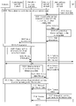
FIG. 1 is an architectural diagram of a system that can apply an application scenario of a communication method in embodiments of this application; -
FIG. 2 is a schematic interaction flowchart of a communication method according to an embodiment of this application; -
FIG. 3 is a schematic interaction flowchart of a communication method according to another embodiment of this application; -
FIG. 4 is a schematic interaction flowchart of a communication method according to another embodiment of this application; -
FIG. 5 is a schematic interaction flowchart of a communication method according to another embodiment of this application; -
FIG. 6 is a schematic interaction flowchart of a communication method according to another embodiment of this application; -
FIG. 7 is a schematic interaction flowchart of a communication method according to another embodiment of this application; -
FIG. 8 is a schematic flowchart of a communication method according to an embodiment of this application; -
FIG. 9 is a schematic flowchart of a communication method according to another embodiment of this application; -
FIG. 10 is a schematic flowchart of a communication method according to another embodiment of this application; -
FIG. 11 is a schematic flowchart of a communication method according to another embodiment of this application; -
FIG. 12 is a schematic flowchart of a communication method according to another embodiment of this application; -
FIG. 13 is a schematic flowchart of a communication method according to another embodiment of this application; -
FIG. 14 is a schematic structural diagram of a database network element according to an embodiment of this application; -
FIG. 15 is a schematic structural diagram of a data analytics network element according to an embodiment of this application; -
FIG. 16 is a schematic structural diagram of a control plane network element according to an embodiment of this application; -
FIG. 17 is a schematic structural diagram of a control plane network element according to another embodiment of this application; -
FIG. 18 is a schematic structural diagram of a user plane network element according to an embodiment of this application; -
FIG. 19 is a schematic structural diagram of a user plane network element according to another embodiment of this application; -
FIG. 20 is a schematic structural diagram of a database network element according to another embodiment of this application; -
FIG. 21 is a schematic structural diagram of a data analytics network element according to another embodiment of this application; -
FIG. 22 is a schematic structural diagram of a control plane network element according to another embodiment of this application; -
FIG. 23 is a schematic structural diagram of a control plane network element according to another embodiment of this application; -
FIG. 24 is a schematic structural diagram of a user plane network element according to another embodiment of this application; -
FIG. 25 is a schematic structural diagram of a user plane network element according to another embodiment of this application; and -
FIG. 26 is a schematic structural diagram of a chip system according to an embodiment of this application. - The following describes the technical solutions in this application with reference to the accompanying drawings.
- As shown in
FIG. 1 , a communications system that can apply a communication method in the embodiments of this application may include a terminal 110, an access network (Access Network, AN)device 120, aUPF network element 130, anAMF network element 140, anSMF network element 150, aPCF network element 160, a network data analytics (Network data Analytics, NWDA)network element 170, and a structured data storage function (Structured Data Storage Function, SDSF)network element 180. - It should be understood that the embodiments of this application are not limited to including a system architecture shown in
FIG. 1 . In addition, an apparatus inFIG. 1 may be hardware, or software obtained based on functional division, or a combination thereof. - The terminal 110 may be user equipment (User Equipment, UE). The terminal 110 may communicate with one or more core networks (Core Network, CN) by using the
AN device 120. The terminal may be referred to as an access terminal, a terminal device, a subscriber unit, a subscriber station, a mobile station, a mobile console, a remote station, a remote terminal, a mobile device, a user terminal, a wireless network device, a user agent, or a user apparatus. The terminal may be a cellular phone, a cordless phone, a session initiation protocol (Session Initiation Protocol, SIP) phone, a wireless local loop (Wireless Local Loop, WLL) station, a personal digital assistant (Personal Digital Assistant, PDA), a handheld device having a wireless communication function, a computing device, another device connected to a wireless modem, a vehicle-mounted device, a wearable device, a terminal device in the internet of things or the internet of vehicles, or a terminal device in any form in a future network. - The AN
device 120 may be specifically a radio access network (Radio Access Network, RAN) device. - In an example, the AN
device 120 is a base station (Base Station, BS). The base station, also referred to as a base station device, is a device connecting the terminal to a wireless network, and includes but is not limited to: a transmission reception point (Transmission Reception Point, TRP), a 5G NodeB (gNB), an evolved NodeB (evolved Node B, eNB), a radio network controller (Radio Network Controller, RNC), a NodeB (Node B, NB), a base station controller (Base Station Controller, BSC), abase transceiver station (Base Transceiver Station, BTS), a home NodeB (for example, a Home evolved nodeB, or a Home Node B, HNB), a baseband unit (Base Band Unit, BBU), a Wifi access point (Access Point, AP), a small cell device (a pico), or the like. - It should be understood that a specific type of the base station is not limited in this embodiment of this application. In systems using different radio access technologies, a device having a base station function may have different names. For ease of description, in all the embodiments of this application, the foregoing apparatus providing a wireless communication function for the terminal is collectively referred to as a base station.
- The
UPF network element 130 has functions such as forwarding, encapsulation, and statistics collection of packets of the terminal. - The
AMF network element 140 is responsible for performing access and mobility management on the terminal. For example, access and mobility management includes managing a mobility status, allocating a temporary identifier to the terminal, authenticating and authorizing the terminal, and the like. - The
SMF network element 150 is responsible for selecting or reselecting a UPF network element, allocating an IP address, and the like, and may further be responsible for session establishment, modification, and releasing, QoS control, and the like. - The
PCF network element 160 may include functions such as policy control, flow-based charging control, terminal subscription data management, QoS control, and the like. - The
NWDA network element 170 may analyze network-level data, and notify another network element of a data analysis result by using theSDSF network element 180. The network-level data includes data generated, stored, and managed by a core network. - The
SDSF network element 180 may store structured data. For example, the structured data includes at least one of application policy data, network topology data, and big-data analysis data in a network. TheSDSF network element 180 may be configured to implement capability exposure inside or outside a network. -
FIG. 2 is a schematic interaction flowchart of a communication method according to an embodiment of this application. It should be understood that, although steps or operations of the communication method are shown inFIG. 2 , the steps or operations are merely an example, and other operations or variations of the operations inFIG. 2 may also be performed in this embodiment of this application. In addition, the steps inFIG. 2 may be performed in a sequence different from that presented inFIG. 2 , and not all the operations inFIG. 2 may be performed. - S201. A database network element collects network data. Optionally, the database network element may collect historical network data from one or more of a terminal, an access network, a control plane network element, and a user plane network element, that is, network data that is generated before the collection.
- The database network element includes but is not limited to an SDSF network element, for example, the
SDSF 180 inFIG. 1 . - The control plane network element includes but is not limited to a control plane function (Control Plane Function, CPF) network element. The CPF network element may include the
AMF network element 140, theSMF network element 150, or thePCF network element 160 shown inFIG. 1 . - The user plane network element may include a user plane function (User Plane Function, UPF) network element. For example, the UPF network element may be the
UPF network element 130 shown inFIG. 1 . - The network data may include a DNN corresponding to a service type to which service transmission data associated with the network data belongs.
- Optionally, step S201 may include: subscribing, by the database network element, to the network data from the control plane network element, and receiving the network data reported by the control plane network element in real-time or periodically.
- The network data includes but is not limited to at least one of an IP address of the terminal, a terminal type (Terminal Type), a cell identifier (Cell ID), a network congestion condition, and a start time for collecting the network data.
- S202. The database network element collects the service transmission data. The service transmission data is specific service data, and may also be referred to as application data.
- For example, the database network element may collect different service types of service transmission data. For example, a voice service, a WeChat service, and an in-vehicle navigation map service belong to different service types. It should be understood that the voice service, the WeChat service, and the in-vehicle navigation map service are merely examples, but should not constitute a limitation on the service type in this embodiment of this application.
- The service transmission data may include at least one of the following information: an IP 5-tuple, a data packet, a size of the data packet, a start time for the service transmission data, a service type, service experience, and an extended field.
- The service transmission data collected by the database network element may include uplink service transmission data and/or downlink service transmission data.
- For example, the database network element may collect the service transmission data from an application platform (Application Platform, AP). The application platform may include an OTT (Over The Top) service center, a vertical management and control center, an operator platform, a third-party service server, or the like.
- The service transmission data collected by the database network element is historical service transmission data, that is, service transmission data previously transmitted in a network.
- It should be understood that a sequence of performing step S201 and step S202 is not limited in this embodiment of this application. For example, step S202 may be performed before step S201, or step S201 may be performed before step S202, or step S201 and step S202 may be performed in an interleaved manner or simultaneously.
- S203. The database network element associates the service transmission data collected in step S202 with the network data collected in step S201, to obtain training data.
- For example, the database network element associates the service transmission data with the network data by using information such as an IP 5-tuple or time, to obtain the training data.
- For example, the service transmission data collected by the database network element includes information such as the IP of the terminal and time, and the time may be the start time for the service transmission data. The network data collected by the database network element also includes information such as the IP of the terminal and time, and the time may be a start time for generating the network data. In this case, the database network element may associate the service transmission data with the network data, to obtain the training data, where the service transmission data and the network data include same information such as the IP of the terminal or the time.
- S204. The database network element sends the training data to a data analytics network element, where the training data includes the service transmission data and the network data that are associated with each other, and correspondingly, the data analytics network element receives the training data.
- The data analytics network element includes but is not limited to an NWDA network element, for example, the
NWDA network element 170 inFIG. 1 . - Optionally, the database network element may proactively send the training data to the data analytics network element; or the data analytics network element may send, to the database network element, a request message for requesting the training data, and the database network element may send the training data to the data analytics network element after receiving the request message sent by the data analytics network element.
- Optionally, if there is a relatively large amount of training data, the database network element may send the training data to the data analytics network element in batches. For example, when the database network element sends the training data to the data analytics network element, if congestion occurs on the network, the database network element may continue to send the training data to the data analytics network element when the network becomes idle.
- S205. The data analytics network element generates first information based on the training data, where the first information includes a first feature index list set, a service identifier corresponding to each feature index list in the first feature index list set, and a DNN corresponding to the service identifier.
- For example, the data analytics network element deployed with feature engineering (Feature Engineering) generates a big data model based on the training data. In the feature engineering, original data is converted into a feature, so that an actual problem processed by a prediction model can be better presented by using the feature, and accuracy of unknown data is improved. In the feature engineering, the feature is obtained through generation, extraction, delete, or combination and variation by using an automated method or based on knowledge in a specific field to which a target problem belongs.
- A process in which the data analytics network element converts the training data into a feature includes the following steps: integrating data, to be specific, integrating the data into one data set; pre-processing the data, to be specific, cleaning, formatting, and sampling the data; converting the data, to be specific, converting the data into key information by using the feature engineering; and modeling the data, to be specific, establishing a model, evaluating the model, and adjusting the model, where the model may also be referred to as the big data model used for identifying a service type.
- The data analytics network element may separate the key information from the training data by using the feature engineering. The key information includes service feature lists corresponding to different service types. The service feature list may be referred to as a feature list for short.
- One service feature list corresponds to one unique service type, so that the unique service type can be identified based on the service feature list.
- Because each service type may have a unique service identifier, after analyzing the training data and obtaining a feature list corresponding to the service type, the data analytics network element may obtain a correspondence between the feature list and the service identifier based on a correspondence between the service type and the service identifier and a correspondence between the service type and the feature list. Each feature list corresponds to one service identifier.
- For example, training data includes service transmission data corresponding to a video service and a payment service, and network data. The data analytics network element performs big data analysis on the training data, to obtain example feature lists corresponding to the video service and the payment service.
- The example feature list corresponding to the video service may include the following features: a size of the first packet in a video service flow (flow), an average value of sizes of all packets in the video service flow, entropy of the sizes of all packets in the video service flow, a use time of the video service, a terminal location, and a cell identifier. The size of the first packet in the video service flow, the average value of the sizes of all packets in the video service flow, the entropy of the sizes of all packets in the video service flow, and the use time of the video service may be obtained by the data analytics network element based on the service transmission data corresponding to the video service, and the terminal location and the cell identifier may be obtained by the data analytics network element based on the network data associated with the service transmission data corresponding to the video service.
- The example feature list corresponding to the payment service may include the following features: an average value of uplink and downlink intervals of all packets in a payment service flow, entropy of the uplink and downlink intervals of all packets in the payment service flow, a use time of the payment service, and a terminal type. The average value of the uplink and downlink intervals of all packets in the payment service flow, the entropy of the uplink and downlink intervals of all packets in the payment service flow, and the use time of the payment service may be obtained by the data analytics network element based on the service transmission data corresponding to the payment service, and the terminal type may be obtained by the data analytics network element based on the network data associated with the service transmission data corresponding to the payment service.
- After obtaining a plurality of feature lists, the data analytics network element may mix these feature lists, or integrate a newly obtained feature list into an existing feature list set and calculate a union set, to obtain a general feature list in which there is no repetitive feature.
- For example, after features in the feature lists corresponding to the video service and the payment service are mixed, a general feature list shown in Table 1 is obtained.
Table 1 General feature list Feature Use time Size of the first packet in a flow Average value of sizes of all packets in a flow Entropy of sizes of all packets in a flow Average value of uplink and downlink intervals of all packets in a flow Entropy of uplink and downlink intervals of all packets in a flow Terminal type Terminal location Cell identifier - The data analytics network element may allocate an index to each feature based on the general feature list. A correspondence between a feature in the general feature list shown in Table 1 and an index is shown in Table 2.
Table 2 Correspondence between a feature and an index Feature Index Use time 1 Size of the first packet in a flow 2 Average value of sizes of all packets in a flow 3 Entropy of sizes of all packets in a flow 4 Average value of uplink and downlink intervals of all packets in a flow 5 Entropy of uplink and downlink intervals of all packets in a flow 6 Terminal type 7 Terminal location 8 Cell (Cell) identifier 9 - After obtaining a general feature index list corresponding to a plurality of service types, the data analytics network element may obtain, based on the general feature index list and feature lists corresponding to different service types, feature index lists corresponding to the different service types.
- For example, a feature index list corresponding to the payment service and a feature index list corresponding to the video service are obtained based on a general feature index list shown in Table 2, and are shown in Table 3.
Table 3 Feature index lists corresponding to the payment service and the video service Service type Feature index list Payment service {1, 5, 6, 7} Video service {1, 2, 3, 4, 8, 9} - Optionally, the feature index list may be extended to binary space. Assuming that the total feature index list includes n features, each feature index list may be represented as an n-dimensional binary character string.
- For example, the general feature list shown in Table 2 includes nine features. In this case, the feature index list may be represented as a binary character string with a length of 9. For example, a binary feature index list corresponding to the payment service may be represented as 100011100, and a binary feature index list corresponding to the video service may be represented as 111100011.
- A plurality of feature index lists obtained by the data analytics network element form one feature index list set, and the feature index list set is referred to as a first feature index list set.
- One service type corresponds to a plurality of feature lists. Correspondingly, one service type corresponds to a plurality of feature index lists.
- For example, network congestion conditions may be different in different geographic locations. Therefore, users may use the payment service at different time, and the data analytics network element may generate, based on the training data, a plurality of feature lists corresponding to the payment service.
- For example, in a working period from 7:00 AM to 17:00 PM, there are about 100,000 users using the payment service in a city A. After the data analytics network element performs big data analysis on training data from the city, a feature index list corresponding to the payment service is shown in Table 4.
Table 4 Feature list corresponding to the payment service (city A, from 7:00 AM to 17:00 PM) Service type Feature list Payment service { use time, average value of uplink and downlink intervals of all packets in a flow, entropy of uplink and downlink intervals of all packets in a flow, terminal type } - For example, in an off-duty period from 17:00 PM to 21:00 PM, a quantity of users using the payment service in the city A greatly increases to 500,000. After the data analytics network element performs big data analysis on training data from the city, a feature index list corresponding to the payment service is shown in Table 5.
Table 5 Feature index list corresponding to the payment service (city A, from 17:00 PM to 21:00 PM) Service type Feature list Payment service { use time, average value of uplink and downlink intervals of all packets in a flow, entropy of uplink and downlink intervals of all packets in a flow, terminal type, terminal location, cell identifier } - For example, in a period from 21:00 PM to 7:00 AM, a quantity of users using the payment service in the city A greatly decreases to 20,000. After the data analytics network element performs big data analysis on training data from the city, a feature index list corresponding to the payment service is shown in Table 6.
Table 6 Feature index list corresponding to the payment service (city A, from 21:00 PM to 7:00 AM) Service type Feature index list Payment service { use time, average value of uplink and downlink intervals of all packets in a flow, entropy of uplink and downlink intervals of all packets in a flow } - It can be learned from Table 4 to Table 6 that feature lists corresponding to the payment service in a busy network and an idle network are different on the same geographic location.
- Based on the correspondence between a feature and an index shown in Table 2, a feature index list corresponding to the feature lists corresponding to the payment service in
FIG. 4 to FIG. 6 is shown in Table 7.Table 7 Feature index lists corresponding to the payment service in the city A Service type Feature list Payment service Feature index list-1: {1, 5, 6, 7} Feature index list-2: {1, 5, 6, 7, 8, 9} Feature index list-3: {1, 5, 6} - In this embodiment of this application, each service type may have a unique service identifier, and in terms of a feature index list, this means that one feature index list corresponds to one service identifier. A plurality of feature lists correspond to one service type, and in terms of a feature index list, this means that a plurality of feature index lists correspond to one service identifier.
- A correspondence between the three feature index lists that are shown in Table 7 and that correspond to the payment service and a service identifier is shown in Table 8. To be specific, a service identifier of the payment service corresponds to the feature index list-1, the feature index list-2, and the feature index list-3. In other words, the feature index list-1, the feature index list-2, and the feature index list-3 all correspond to the service identifier of the payment service.
Table 8 Correspondence between the service identifier of the payment service and the plurality of feature index lists Service identifier Feature index list Service identifier of the payment service Feature index list-1 Feature index list-2 Feature index list-3 - It should be understood that Table 8 is merely an example in which the plurality of feature index lists correspond to the same service identifier, but should not constitute a limitation on an expression form or a storage form of the correspondence between the feature index lists and the service identifier. For example, the correspondence between the service identifier of the payment service and the plurality of feature index lists may be shown in Table 9.
Table 9 Correspondence between the service identifier of the payment service and the plurality of feature index lists Service identifier Feature index list Service identifier of the payment service Feature index list-1 Service identifier of the payment service Feature index list-2 Service identifier of the payment service Feature index list-3 - Because the network data may include a DNN corresponding to a service type, after obtaining a feature index list corresponding to the service type and a correspondence between the feature index list and a service identifier, the data analytics network element may further obtain a correspondence between the DNN corresponding to the service type and the service identifier corresponding to the service type.
- An example of a correspondence between a DNN, a service identifier, and a feature index list is shown in Table 10.
Table 10 Correspondence between a DNN, a service identifier, and a feature index list DNN Service identifier Feature index list DNN-1 Service identifier 1 {1, 5, 6, 7} Service identifier 2 {1, 2, 3, 4, 8, 9} DNN-2 Service identifier 3 {1, 4, 7, ..., 19} {1, 2, 3, ..., 1000} DNN-3 Service identifier 4 {1, 2, 3, ..., 200} - It should be understood that an expression form of the correspondence between a DNN, a service identifier, and a feature index list in Table 10 is merely an example, but should not constitute a limitation on this embodiment of this application. The correspondence between a DNN, a service identifier, and a feature index list may have another expression form, for example, an expression form shown in Table 11.
Table 11 Correspondence between a DNN, a service identifier, and a feature index list DNN Service identifier Feature index list DNN-1 Service identifier 1 {1, 5, 6, 7} DNN-1 Service identifier 2 {1, 2, 3, 4, 8, 9} DNN-2 Service identifier 3 {1, 4, 7, ..., 19} DNN-2 Service identifier 3 {1, 2, 3, ..., 1000} DNN-3 Service identifier 4 {1, 2, 3, ..., 200} - Table 10 or Table 11 includes five feature index lists, each of the five feature index lists corresponds to a unique service identifier, and four service types corresponding to the five feature index lists correspond to three different DNNs.
- It should be understood that the quantity 5 of the feature index lists, the maximum quantity 1000 of feature indexes, the quantity 3 of the DNNs, and a quantity of service identifiers corresponding to each DNN network that are shown in Table 10 or Table 11 are merely an example, but should not constitute a limitation on this embodiment of this application.
- S206. The data analytics network element sends first information to the database network element, and correspondingly, the database network element receives the first information.
- Optionally, the first information may further include a correspondence between a feature and an index. For example, the first information may include the correspondence shown in Table 2. In this way, the database network element can learn of a feature corresponding to a feature index in each feature index list in the first feature index set.
- Optionally, after receiving the first information, the database network element may store the first information.
- In a possible design, after receiving the first information, the database network element may store the first information in the following manner: The database network element may store, by using a service identifier as data index information, a feature index list corresponding to each service identifier and a DNN corresponding to each service identifier.
- In another possible design, after receiving the first information, the database network element may store the first information in the following manner: The database network element may store, by using a DNN as data index information, a service identifier corresponding to each DNN and a feature index list corresponding to each service identifier.
- S207. The database network element sends the first information to the control plane network element, and correspondingly, the control plane network element receives the first information.
- When the first information sent by the data analytics network element to the database network element includes the correspondence between a feature and an index, the first information sent by the database network element to the control plane network element may also include the correspondence between a feature and an index.
- The control plane network element may be an AMF network element, an SMF network element, a PCF network element, or another control plane function network element. For example, the control plane network element may be the
AMF network element 140, theSMF network element 150, or thePCF network element 160 shown inFIG. 1 . - Optionally, after receiving the first information, the control plane network element may store the first information.
- When the control plane network element is the SMF network element or the PCF network element, the database network element may directly deliver the first information to the SMF network element or the PCF network element or deliver the first information to the SMF network element or the PCF network element by using a network exposure function (Network Exposure Function, NEF) network element.
- S208. The terminal initiates a process for modifying an existing session or a process for establishing a new session. For ease of subsequent description, the session is referred to as a first session.
- Optionally, the first session may be a service data flow (Service Data Flow), and the first session may be identified by using an IP 5-tuple.
- When UE initiates the first session, a DNN associated with the first session is added. For ease of subsequent description, the DNN associated with the first session may be referred to as a first DNN.
- S209. The control plane network element queries the first information based on the first DNN to obtain second information, where the second information includes a second feature index list set corresponding to the first DNN and a service identifier corresponding to each feature index list in the second feature index list set.
- Specifically, the control plane network element may screen the locally stored first information based on the first DNN, and find a feature index list and a service identifier that correspond to the first DNN. The feature index list that corresponds to the first DNN and that is obtained by screening the first information forms the second feature index list set.
- The control plane network element generates the second information based on the second feature index list set and the service identifier obtained through the screening, where the second information includes the second feature index list set and the service identifier obtained through the screening.
- For example, when the first information received by the control plane network element from the database network element includes content shown in Table 11, if the first DNN is the DNN-1, the control plane network element may generate the second information based on Table 11, where the second information may include content shown in Table 12.
Table 12 Service identifier and feature index list included in the second information Service identifier Feature index list Service identifier 1 {1, 5, 6, 7} Service identifier 2 {1, 2, 3, 4, 8, 9} - Optionally, when the first information received by the control plane network element from the database network element includes the correspondence between a feature and an index, the second information sent by the control plane network element to the user plane network element may also include the correspondence.
- In this case, the user plane network element may locally store the correspondence between a feature and an index. When the control plane network element subsequently sends the second information corresponding to a service type to the user plane network element again, the second information can include only a feature index list corresponding to the service type, and the user plane network element may obtain, based on the stored correspondence between a feature and an index, a feature list corresponding to the feature index list.
- S210. The control plane network element sends the second information to the user plane network element, and correspondingly, the user plane network element receives the second information.
- The user plane network element includes but is not limited to a UPF network element. For example, the user plane network element may be the
UPF network element 130 shown inFIG. 1 . - Further, the control plane network element sending the second information to the user plane network element may be the SMF network element.
- Further, after the SMF network element receives the first information from the database network element, when the terminal initiates the first session, the SMF network element determines the second information based on the first information, and sends the second information to the user plane network element.
- Alternatively, after the PCF network element receives the first information from the database network element, when the terminal initiates the first session, the SMF network element obtains, from the PCF network element, the second information determined by the PCF network element based on the first information, and the SMF network element sends the second information to the UPF network element.
- The foregoing implementation in which the control plane network element sends the second information to the user plane network element is merely an example, but should not constitute a limitation on this embodiment of this application.
- S211. The user plane network element receives service transmission data corresponding to the terminal.
- It should be understood that the service transmission data may be uplink service transmission data or downlink service transmission data.
- It should be understood that step S211 may be alternatively performed before step S209 or step S210.
- S212. The user plane network element obtains an eigenvalue from the service transmission data.
- For example, the user plane network element obtains, from the service transmission data, an eigenvalue list corresponding to each feature index list in the second feature index list set.
- For example, when the second feature index list set includes the feature index lists in Table 12, and the feature indexes in Table 12 include the indexes in Table 2, the user plane network element may obtain eigenvalues corresponding to the features "use time", "size of the first packet in a flow", "average value of sizes of all packets in a flow", "entropy of sizes of all packets in a flow", "average value of uplink and downlink intervals of all packets in a flow", and "entropy of uplink and downlink intervals of all packets in a flow" that correspond to the
feature indexes 1, 2, 3, 4, 5, and 6. - For example, the user plane network element may obtain, from the service transmission data, eigenvalues shown in Table 13.
Table 13 Eigenvalue obtained based on the service transmission data Feature Feature index Eigenvalue Use time 1 9:00 AM Size of the first packet in a flow 2 20 bits Average value of sizes of all packets in a flow 3 30 bits Entropy of sizes of all packets in a flow 4 2 Average value of uplink and downlink intervals of all packets in a flow 5 10 milliseconds Entropy of uplink and downlink intervals of all packets in a flow 6 1.5 Terminal type 7 Terminal location 8 Cell identifier 9 - It can be learned from Table 13 that because the terminal type, the terminal location, and the cell identifier all belong to the network data, the user plane network element cannot obtain, based on the service transmission data, eigenvalues corresponding to the terminal type, the terminal location, and the cell identifier that respectively correspond to the feature indexes 7, 8, and 9. Next, the user plane network element performs step S213.
- S213. The user plane network element sends third information to the database network element, where the third information includes a first service identifier set, and correspondingly, the database network element receives the third information sent by the user plane network element.
- For example, after obtaining the eigenvalue from the service transmission data, the user plane network element determines all feature indexes that are in the second feature index list set and for which eigenvalues cannot be obtained based on the service transmission data. For ease of subsequent description, a feature index list including the feature indexes that are in the second feature index list set and for which the eigenvalues cannot be obtained based on the service transmission data is referred to as a first network data feature index list.
- Because the training data includes the network data, when a feature index list is generated based on the training data, the feature index list may include a feature index corresponding to the network data. An eigenvalue corresponding to the feature index corresponding to the network data cannot be obtained from the service transmission data. The user plane network element may screen out the feature index for which the eigenvalue cannot be obtained from the service transmission data, to obtain the first network data feature index list.
- For example, the user plane network element cannot obtain, from the service transmission data, the eigenvalues corresponding to the features "terminal type", "terminal location", and "cell identifier" that correspond to the feature indexes 7, 8, and 9 in Table 12. In other words, the feature indexes 7, 8, and 9 form the first network data feature index list shown in Table 14.
Table 14 First network data feature index list Feature index 7 8 9 - After obtaining the first network data feature index list, the user plane network element may remove a repetitive feature index in the first network data index list, to obtain a first network data feature index list in which there is no repetitive feature index.
- After determining the first network data feature index list, the user plane network element may determine a service identifier corresponding to a feature index list to which each feature index in the first network data feature index list belongs. Service identifiers corresponding to all the feature indexes in the first network data feature index list form the first service identifier set.
- For example, a service identifier corresponding to the feature index 7 that is in Table 12 and for which an eigenvalue cannot be obtained based on the service transmission data is the
service identifier 1, and a service identifier corresponding to the indexes 8 and 9 that are in Table 12 and for which eigenvalues cannot be obtained based on the service transmission data is the service identifier 2. Therefore, a correspondence between a first network data feature index list and a service identifier shown in Table 15 can be obtained.Table 15 Correspondence between a first network data feature index list and a service identifier Index Service identifier 7 Service identifier 18 Service identifier 2 9 Service identifier 2 - The user plane network element may obtain, based on Table 15, the first service identifier set including the
service identifier 1 and the service identifier 2, where the first service identifier set is shown in Table 16.Table 16 First service identifier set Service identifier Service identifier 1 Service identifier 2 - S214. The database network element collects network data corresponding to the first session.
- The network data corresponding to the first session may include a type of the terminal initiating the first session, a time at which the terminal initiates the first session, an identifier of a cell in which the terminal is located, and the like.
- It should be understood that an execution sequence of step S214 is not limited in this embodiment of this application. Optionally, step S214 may be performed at any time between step S208 and step S213.
- S215. The database network element sends a network data eigenvalue list to the user plane network element, and correspondingly, the user plane network element receives the network data eigenvalue list.
- Specifically, the database network element collects the network data corresponding to the first session, and after receiving the third information sent by the user plane network element, the database network element may determine a feature index that is in a feature index list corresponding to each service identifier in the first service identifier set and that corresponds to the network data. A feature list including feature indexes that are in feature index lists corresponding to all service identifiers in the first service identifier set and that correspond to the network data may be referred to as a second network data feature index list.
- After determining the second network data feature index list, the database network element obtains, from the collected network data corresponding to the first session, an eigenvalue of a feature corresponding to each feature index in the second network data feature index list. An eigenvalue list including the eigenvalue that is of the feature corresponding to each feature index in the second network data feature index list and that is obtained from the network data corresponding to the first session may be referred to as the network data eigenvalue list.
- For example, when the first service identifier set includes the
service identifier 1 and the service identifier 2 in Table 16, the database network element may obtain, from the network data corresponding to the first session, data eigenvalues corresponding to the features "terminal type", "terminal location", and "cell identifier". - An example in which the database network element obtains the network data eigenvalue list is as follows: The database network element obtains the
service identifier 1 and the service identifier 2 in the first service identifier set based on the first service identifier set in Table 16; and the database network element further finds, based on the first information obtained in step S206, that the "terminal type" corresponding to the feature index 7 corresponding to theservice identifier 1 belongs to the network data, and determines, based on the network data obtained in step S214, an eigenvalue corresponding to the "terminal type". Similarly, the database network element determines eigenvalues based on the network data obtained in step S214, the "terminal location" corresponding to the feature index 8 corresponding to the service identifier 2, and the "cell identifier" corresponding to the feature index 9 corresponding to the service identifier 2, where the eigenvalues correspond to the "terminal location" and the "cell identifier". - An example of the network data eigenvalue list obtained by the database network element is shown in Table 17.
Table 17 Network data eigenvalue list corresponding to the first service identifier set Service identifier Feature index Eigenvalue Service identifier 1 7 Huawei P10 Service identifier 2 8 Haidian District Service identifier 2 9 Cell ID-1 - The database network element may send the network data eigenvalue list shown in Table 17 to the user plane network element.
- S216. The user plane network element sends the second feature index list set and the eigenvalue list corresponding to each feature index list in the second feature index list set to the data analytics network element, where the second feature index list set and the eigenvalue list corresponding to each feature index list in the second feature index list set correspond to the first session.
- The eigenvalue sent by the user plane network element to the data analytics network element includes not only the eigenvalue corresponding to the service transmission data, but also includes the network data eigenvalue. Correspondingly, the data analytics network element receives the foregoing eigenvalue from the user plane network element.
- For example, the user plane network element may send, based on Table 13 and Table 17, an eigenvalue list shown in Table 18 to the data analytics network element. The eigenvalue list corresponds to the first session.
Table 18 Eigenvalue list corresponding to the first session Feature index list Eigenvalue list {1,5,6,7} {9:00 AM, 10 milliseconds, 1.5, Huawei P10} {1, 2, 3, 4, 8, 9} {9:00 AM, 20 bits, 30 bits, 2, Haidian, Cell ID-1} - S217. The data analytics network element determines, based on the second feature index list set and the eigenvalue list corresponding to each feature index list in the second feature index list set, a service type corresponding to a data packet corresponding to the first session, where the second feature index list set and the eigenvalue list are received from the user plane network element.
- Specifically, the data analytics network element may use the second feature index list set and the eigenvalue list corresponding to each feature index list in the second feature index list set that are sent by the user plane network element, as input parameters of the big data model generated in step S205. An output result of the big data model is the service type corresponding to the data packet corresponding to the first session.
- Although the eigenvalue list sent by the user plane network element to the data analytics network element in step S216 includes both feature index list sets corresponding to the
service identifier 1 and the service identifier 2 and an eigenvalue list corresponding to each feature index list in the feature index list sets, the service type determined by the data analytics network element can be only one of the two service types. In other words, the feature index list set and the eigenvalue list corresponding to each feature index list in the feature index list set that are sent by the user plane network element correspond to a unique service type. - S218. The data analytics network element sends, to the user plane network element, the service type determined in step S217, and correspondingly, the user plane network element receives the service type.
- In this embodiment of this application, all the network elements operate jointly to identifying the service type. In addition, the database network element may be deployed close to an application server and a core network network element in a distributed manner. Therefore, delays caused during obtaining the training data and delivering the first information can be reduced.
- In the communication method in this embodiment of this application, the data analytics network element can determine, based on the network data and the service transmission data that correspond to the terminal, the service type corresponding to the terminal, thereby improving identification accuracy.
- In this embodiment of this application, optionally, the first information may further include at least one of the following information corresponding to each feature index list in the first feature index list set: a network slice type, an SSC mode, and a PDU session type.
- If the first information further includes the at least one of the network slice type, the SSC mode, and the PDU session type, in step S209, when the control plane network element queries the first information to obtain the second information, the control plane network element may screen out the second information based on both the DNN corresponding to the first session and the at least one of the network slice type, the SSC mode, and the PDU session type that correspond to the first session.
- In other words, the second information is obtained by screening the first information, and each feature index list in the second feature index list set in the second information corresponds to the DNN corresponding to the first session and corresponds to the at least one of the network slice type, the SSC mode, and the PDU session type that correspond to the first session.
- In this way, more accurate second information can be obtained, accuracy of an eigenvalue obtained by the user plane network element based on the second information can be improved, and finally service type identification accuracy is improved.
- In this embodiment of this application, optionally, if the first service identifier set determined by the database network element is empty, step S213 and step S215 or even step S214 may be skipped in this embodiment of this application.
- In this embodiment of this application, optionally, in step S213, the third information may further carry at least one of the following information: a time at which the user plane network element receives the service transmission data corresponding to the first session, a session identifier of the first session, an identifier of the terminal corresponding to the first session, an IP address of the terminal corresponding to the first session, a port on the terminal corresponding to the first session, an IP address of a service server corresponding to the first session, a port that is on the service server and that corresponds to the first session, and a service transmission protocol for the service transmission data corresponding to the first session.
- In this way, the database network element may further obtain, based on the at least one of the information carried in the third information, an eigenvalue corresponding to the network data that satisfies the at least one of the information. For example, the third information sent by the user plane network element to the database network element may carry the IP address of the terminal, the IP address of the terminal is used to identify the terminal, and the database network element determines, based on the IP address of the terminal, the network data corresponding to the terminal. Therefore, the service type identification accuracy can be further improved.
- In step S214 in this embodiment of this application, when collecting the network data corresponding to the first session, the database network element may further collect the network data based on one or more of information corresponding to the first session, such as the DNN, the IP of the terminal, the ID of the terminal, and a PDU session ID, where the network data corresponding to the first session.
- In step S213 and step S215 in this embodiment of this application, the user plane network element may directly communicate with the database network element or communicate with the database network element by using the SMF network element.
-
FIG. 3 is a schematic interaction flowchart of a communication method according to an embodiment of this application. It should be understood that, although steps or operations of the communication method are shown inFIG. 3 , the steps or operations are merely an example, and other operations or variations of the operations inFIG. 3 may also be performed in this embodiment of this application. In addition, the steps inFIG. 3 may be performed in a sequence different from that presented inFIG. 3 , and not all the operations inFIG. 3 may be performed. - For steps S301 to S312, refer to steps S201 to S212 in
FIG. 2 . For brevity, details are not described herein again. - S313. The user plane network element sends third information to the database network element, where the third information carries a network data feature index list, and correspondingly, the database network element receives the third information sent by the user plane network element.
- For example, after obtaining the eigenvalue from the service transmission data, the user plane network element determines all feature indexes that are in the second feature index list set and for which eigenvalues cannot be obtained based on the service transmission data. The feature indexes that are in the second feature index list set and for which the eigenvalues cannot be obtained based on the service transmission data form the network data feature index list.
- In other words, because the training data includes the network data, when the feature index list is generated based on the training data, the feature index list may include a feature index corresponding to the network data. An eigenvalue corresponding to the feature index corresponding to the network data cannot be obtained from the service transmission data. The user plane network element may screen out the feature index for which the eigenvalue cannot be obtained from the service transmission data, to obtain the network data feature index list.
- For example, the user plane network element cannot obtain, from the service transmission data, the eigenvalues corresponding to the features "terminal type", "terminal location", and "cell identifier" that correspond to the feature indexes 7, 8, and 9 in Table 12. In other words, the feature indexes 7, 8, and 9 form the network data feature index list.
- After obtaining the network data feature index list, the user plane network element may remove a repetitive feature index in the network data feature index list, to obtain a network data feature index list in which there is no repetitive feature index.
- For step S314, refer to step S214 in
FIG. 2 . Details are not described herein again. - S315. The database network element sends the network data eigenvalue list to the user plane network element, and correspondingly, the user plane network element receives the network data eigenvalue list from the database network element.
- For example, the database network element obtains, from the collected network data corresponding to the first session, an eigenvalue of a feature corresponding to each feature index in the network data feature index list. An eigenvalue list including the eigenvalue that corresponds to each feature index in the network data feature index list and that is obtained from the network data corresponding to the first session may be referred to as the network data eigenvalue list.
- For example, when the network data feature index list includes the feature indexes 7, 8, and 9, the database network element may obtain, from the network data corresponding to the first session, network data eigenvalues corresponding to the features "terminal type", "terminal location", and "cell identifier".
- For steps S316 to S318, refer to steps S216 to S218 in
FIG. 2 . Details are not described herein again. -
FIG. 4 is a schematic interaction flowchart of a communication method according to an embodiment of this application. It should be understood that, although steps or operations of the communication method are shown inFIG. 4 , the steps or operations are merely an example, and other operations or variations of the operations inFIG. 4 may also be performed in this embodiment of this application. In addition, the steps inFIG. 4 may be performed in a sequence different from that presented inFIG. 4 , and not all the operations inFIG. 4 may be performed. - For steps S401 to S412, refer to steps S201 to S212 in
FIG. 2 . For brevity, details are not described herein again. - S413. The user plane network element sends third information to the database network element, where the third information is used to request network data corresponding to the first session, and correspondingly, the database network element receives the third information sent by the user plane network element.
- For example, after obtaining the eigenvalue from the service transmission data, the user plane network element determines whether the second feature index list set includes a feature index for which an eigenvalue cannot be obtained based on the service transmission data.
- If the second feature index list set includes the feature index for which the eigenvalue cannot be obtained based on the service transmission data, the user plane network element sends the third information to the database network element, to request the network data corresponding to the first session. For ease of subsequent description, an index list including the feature index that is in the second feature index list set and for which the eigenvalue cannot be obtained based on the service transmission data is referred to as a network data feature index list.
- Because the training data includes the network data, when the feature index list is generated based on the training data, the feature index list may include a feature index corresponding to the network data. In other words, the eigenvalue that cannot be obtained based on the service transmission data may be obtained from the network data. Therefore, the user plane network element may send, to the database network element, the third information for requesting the network data.
- For example, the user plane network element cannot obtain, from the service transmission data, the eigenvalues corresponding to the features "terminal type", "terminal location", and "cell identifier" that correspond to the feature indexes 7, 8, and 9 in Table 12. In this case, the user plane network element sends the third information to the database network element, to request the network data corresponding to the first session.
- For example, the third information may include a time at which the user plane network element receives the service transmission data corresponding to the first session, a session identifier of the first session, an identifier of the terminal corresponding to the first session, an IP address of the terminal corresponding to the first session, a port on the terminal corresponding to the first session, an IP address of a service server corresponding to the first session, a port that is on the service server and that corresponds to the first session, and a service transmission protocol for the service transmission data corresponding to the first session.
- S414. The database network element may collect, based on the third information, the network data corresponding to the first session.
- For example, the database network element may collect network data that satisfies at least one of the following conditions: the time at which the user plane network element receives the service transmission data corresponding to the first session, the session identifier of the first session, the identifier of the terminal corresponding to the first session, the IP address of the terminal corresponding to the first session, the port on the terminal corresponding to the first session, the IP address of the service server corresponding to the first session, the port that is on the service server and that corresponds to the first session, and the service transmission protocol for the service transmission data corresponding to the first session.
- S415. The database network element sends the network data to the user plane network element, and correspondingly, the user plane network element receives the network data from the database network element.
- After receiving, from the database network element, the network data corresponding to the first session, the user plane network element obtains, from the network data corresponding to the first session, an eigenvalue of a feature corresponding to a feature index in the network data feature index list. A list including the eigenvalue of the feature corresponding to the feature index in the network data feature index list may be referred to as a network data eigenvalue list.
- For steps S416 to S418, refer to steps S216 to S218 in
FIG. 2 . Details are not described herein again. -
FIG. 5 is a schematic interaction flowchart of a communication method according to an embodiment of this application. It should be understood that, although steps or operations of the communication method are shown inFIG. 5 , the steps or operations are merely an example, and other operations or variations of the operations inFIG. 5 may also be performed in this embodiment of this application. In addition, the steps inFIG. 5 may be performed in a sequence different from that presented inFIG. 5 , and not all the operations inFIG. 5 may be performed. - For steps S501 to S506, respectively refer to corresponding steps S201 to S206. For brevity, details are not described herein again.
- For step S507, refer to step S208. For brevity, details are not described herein again.
- S508. The control plane network element sends a DNN corresponding to a first session to the database network element, and correspondingly, the database network element receives, from the control plane network element, the DNN corresponding to the first session.
- S509. The database network element queries the first information based on the DNN corresponding to the first session, to obtain second information, where the second information includes a second feature index list set and a service identifier corresponding to a service type corresponding to each feature index list in the second feature list set.
- The database network element queries the first information based on the first DNN associated with the first session, to obtain the second information, where the second information includes the second feature index list set corresponding to the first DNN and the service identifier corresponding to each feature index list in the second feature index list set.
- In other words, the database network element may screen the locally stored first information based on the first DNN, and find a feature index list and a service identifier that correspond to the first DNN. The feature index list that corresponds to the first DNN and that is obtained by screening the first information forms the second feature index list set.
- The database network element generates the second information based on the second feature index list set and the service identifier obtained through the screening, where the second information includes the second feature index list set and the service identifier obtained through the screening.
- For example, when the first information received by the database network element from the data analytics network element includes content shown in Table 11, if the first DNN is the DNN-1, the database network element may generate the second information based on Table 11, where the second information may include content shown in Table 12.
- Optionally, when the first information received by the database network element from the data analytics network element includes the correspondence between a feature and an index, the second information sent by the database network element to the control plane network element may also include the correspondence.
- In this case, the control plane network element may locally store the general feature list. When the database network element subsequently sends the second information corresponding to a service type to the control plane network element again, the second information can include only a feature index list corresponding to the service type. The control plane network element may send the correspondence between a feature and an index to the user plane network element, so that the user plane network element can obtain, based on the correspondence, a feature list corresponding to the feature index list in the second information.
- S510. The database network element sends the second information to the control plane network element, and correspondingly, the control plane network element receives the second information sent by the database network element.
- For steps S511 to S519, refer to corresponding steps S210 to S218. For brevity, details are not described herein again.
- In this embodiment of this application, optionally, in step S508, the control plane network element may further send, to the database network element, at least one of the following information: a network slice type, an SSC mode, and a PDU session type. Correspondingly, the database network element further receives, from the CPF network element, the at least one of the information corresponding to the first session.
- Correspondingly, in step S509, when querying for the second information from the first information, the database network element may further obtain the second information based on both the DNN corresponding to the first session and the at least one of the information corresponding to the first session. Therefore, more accurate second information is obtained, and service type identification accuracy is improved.
- In this embodiment of this application, optionally, the second information may further include at least one of the following information corresponding to each feature index list in the second feature index list set: a DNN, a network slice type, a service and an SSC mode, and a PDU session type.
- When the second information further includes the at least one of the information corresponding to each feature index list in the second feature index list set, if the terminal initiates a second session or another terminal initiates a second session, the control plane network element may determine, based on the at least one of the information corresponding to each feature index list in the second feature index list set, whether the second feature index list set includes a feature index list corresponding to the second session.
- If the control plane network element determines, based on the at least one of the information corresponding to each feature index list in the second feature index list set, that the second feature index list set includes the feature index list corresponding to the second session, the control plane network element may skip requesting the second information from the database network element, thereby improving service type identification efficiency.
-
FIG. 6 is a schematic interactive flowchart of a communication method according to an embodiment of this application. It should be understood that, although steps or operations of the communication method are shown inFIG. 6 , the steps or operations are merely an example, and other operations or variations of the operations inFIG. 6 may also be performed in this embodiment of this application. In addition, the steps inFIG. 6 may be performed in a sequence different from that presented inFIG. 6 , and not all the operations inFIG. 6 may be performed. - For steps S601 to S613, refer to steps S501 to S513 in
FIG. 5 . For brevity, details are not described herein again. - For steps S614 to S616, refer to steps S313 to S315 in
FIG. 3 . For brevity, details are not described herein again. - For steps S617 to S619, refer to steps S517 to S519 in
FIG. 5 . For brevity, details are not described herein again. -
FIG. 7 is a schematic interactive flowchart of a communication method according to an embodiment of this application. It should be understood that, although steps or operations of the communication method are shown inFIG. 7 , the steps or operations are merely an example, and other operations or variations of the operations inFIG. 7 may also be performed in this embodiment of this application. In addition, the steps inFIG. 7 may be performed in a sequence different from that presented inFIG. 7 , and not all the operations inFIG. 7 may be performed. - For steps S701 to S713, refer to steps S501 to S513 in
FIG. 5 . For brevity, details are not described herein again. - For steps S714 to S716, refer to steps S413 to S415 in
FIG. 4 . For brevity, details are not described herein again. - For steps S717 to S719, refer to steps S517 to S519 in
FIG. 5 . For brevity, details are not described herein again. - In the communication method shown in
FIG. 2 , optionally, when application data on an application platform changes, for example, when a version of an application is upgraded, the database network element may re-perform steps S201 to S207. - In the communication method shown in
FIG. 3 , optionally, when application data on an application platform changes, for example, when a version of an application is upgraded, the database network element may re-perform steps S301 to S307. - In the communication method shown in
FIG. 4 , optionally, when application data on an application platform changes, for example, when a version of an application is upgraded, the database network element may re-perform steps S401 to S407. - In the communication method shown in
FIG. 5 , optionally, when application data on an application platform changes, for example, when a version of an application is upgraded, the database network element may re-perform steps S501 to S506. - In the communication method shown in
FIG. 6 , optionally, when application data on an application platform changes, for example, when a version of an application is upgraded, the database network element may re-perform steps S601 to S606. - In the communication method shown in
FIG. 7 , optionally, when application data on an application platform changes, for example, when a version of an application is upgraded, the database network element may re-perform steps S701 to S706. - The foregoing describes the schematic interaction flowcharts of the communication method in the embodiments of this application with reference to
FIG. 2 to FIG. 7 . The following describes a communication method on a single side in the embodiments of this application with reference toFIG. 8 to FIG. 13 . -
FIG. 8 is a schematic flowchart of a communication method according to an embodiment of this application. It should be understood that, although steps or operations of the communication method are shown inFIG. 8 , the steps or operations are merely an example, and other operations or variations of the operations inFIG. 8 may also be performed in this embodiment of this application. In addition, the steps inFIG. 8 may be performed in a sequence different from that presented inFIG. 8 , and not all the operations inFIG. 8 may be performed. - S801. A database network element obtains training data, where the training data includes service transmission data and network data.
- For details, for example, refer to step S201 to step S203 in
FIG. 2 , step S301 to step S303 inFIG. 3 , step S401 to step S403 inFIG. 4 , step S501 to S503 inFIG. 5 , step 601 to step 603 inFIG. 6 , or step S701 to step S703 inFIG. 7 . - S802. The database network element sends the training data to a data analytics network element.
- For details, for example, refer to step S204 in
FIG. 2 , step S304 inFIG. 3 , step S404 inFIG. 4 , step S504 inFIG. 5 , step S604 inFIG. 6 , or step S704 inFIG. 7 . - S803. The database network element receives first information from the data analytics network element, where the first information includes a first feature index list set, a service identifier corresponding to each feature index list in the first feature index list set, and a DNN corresponding to the service identifier.
- For details, for example, refer to step S206 in
FIG. 2 , step S306 inFIG. 3 , step S406 inFIG. 4 , step S506 inFIG. 5 , step S606 inFIG. 6 , or step S706 inFIG. 7 . - Optionally, the communication method shown in
FIG. 8 may further include: sending, by the database network element, the first information to a control plane network element. - For details, for example, refer to step S207 in
FIG. 2 , step S307 inFIG. 3 or step S407 inFIG. 4 . - Optionally, the communication method shown in
FIG. 8 may further include: receiving, by the database network element from the control plane network element, a DNN corresponding to a first session; querying, by the database network element, the first information based on the DNN corresponding to the first session, to obtain second information, where the second information includes a second feature index list set corresponding to the DNN corresponding to the first session and a service identifier corresponding to each feature index list in the second feature index list set; and sending, by the database network element, the second information to the control plane network element. - For details, for example, refer to step S509 in
FIG. 5 , step S609 inFIG. 6 or step S709 inFIG. 7 . - Optionally, the communication method shown in
FIG. 8 may further include: receiving, by the database network element, third information from a user plane network element, where the third information includes a first service identifier set; querying, by the database network element, the first information to obtain a feature index list corresponding to each service identifier in the first service identifier set; querying, by the database network element, the network data based on the feature index list corresponding to each service identifier in the first service identifier set, to obtain a network data eigenvalue list corresponding to each service identifier in the first service identifier set; and sending, by the database network element, the network data eigenvalue list corresponding to each service identifier in the first service identifier set to the user plane network element. - For details, for example, refer to steps S213 to S215 in
FIG. 2 or steps S514 to S516 inFIG. 5 . -
FIG. 9 is a schematic flowchart of a communication method according to an embodiment of this application. It should be understood that, although steps or operations of the communication method are shown inFIG. 9 , the steps or operations are merely an example, and other operations or variations of the operations inFIG. 9 may also be performed in this embodiment of this application. In addition, the steps inFIG. 9 may be performed in a sequence different from that presented inFIG. 9 , and not all the operations inFIG. 9 may be performed. - S901. A data analytics network element receives training data from a database network element, where the training data includes service transmission data and network data.
- For details, for example, refer to step S204 in
FIG. 2 , step S304 inFIG. 3 , step S404 inFIG. 4 , step S504 inFIG. 5 , step S604 inFIG. 6 , or step S704 inFIG. 7 . - S902. The data analytics network element determines first information based on the training data, where the first information includes a first feature index list set, a service identifier corresponding to each feature index list in the first feature index list set, and a DNN corresponding to the service identifier.
- For details, for example, refer to step S205 in
FIG. 2 , step S305 inFIG. 3 , step S405 inFIG. 4 , step S505 inFIG. 5 , step S605 inFIG. 6 , or step S705 inFIG. 7 . - S903. The data analytics network element sends the first information to the database network element.
- For details, for example, refer to step S206 in
FIG. 2 , step S306 inFIG. 3 , step S406 inFIG. 4 , step S506 inFIG. 5 , step S606 inFIG. 6 , or step S706 inFIG. 7 . -
FIG. 10 is a schematic flowchart of a communication method according to an embodiment of this application. It should be understood that, although steps or operations of the communication method are shown inFIG. 10 , the steps or operations are merely an example, and other operations or variations of the operations inFIG. 10 may also be performed in this embodiment of this application. In addition, the steps inFIG. 10 may be performed in a sequence different from that presented inFIG. 10 , and not all the operations inFIG. 10 may be performed. - S1001. A control plane network element receives first information from a database network element, where the first information includes a first feature index list set, a service identifier corresponding to each feature index list in the first feature index list set, and a DNN corresponding to the service identifier.
- For details, for example, refer to step S207 in
FIG. 2 , step S307 inFIG. 3 , or step S407 inFIG. 4 . - S1002. The control plane network element queries the first information based on a DNN corresponding to a first session, to obtain second information, where the second information includes a second feature index list set corresponding to the DNN corresponding to the first session and a service identifier corresponding to each feature index list in the second feature index list set.
- For details, for example, refer to step S209 in
FIG. 2 , step S309 inFIG. 3 , or step S409 inFIG. 4 . - S1003. The control plane network element sends the second information to a user plane network element.
- For details, for example, refer to step S210 in
FIG. 2 , step S310 inFIG. 3 , or step S410 inFIG. 4 . -
FIG. 11 is a schematic flowchart of a communication method according to an embodiment of this application. It should be understood that, although steps or operations of the communication method are shown inFIG. 11 , the steps or operations are merely an example, and other operations or variations of the operations inFIG. 11 may also be performed in this embodiment of this application. In addition, the steps inFIG. 11 may be performed in a sequence different from that presented inFIG. 11 , and not all the operations inFIG. 11 may be performed. - S1101. A control plane network element sends a DNN corresponding to a first session to a database network element.
- For details, for example, refer to step S508 in
FIG. 5 , step S608 inFIG. 6 , or step S708 inFIG. 7 . - S1102. The control plane network element receives second information from the database network element, where the second information includes a second feature index list set and a service identifier corresponding to each feature index list in the second feature index list set, and the service identifier corresponds to the DNN.
- For details, for example, refer to step S510 in
FIG. 5 , step S610 inFIG. 6 , or step S710 inFIG. 7 . - S1103. The control plane network element sends the second information to a user plane network element.
- For details, for example, refer to step S511 in
FIG. 5 , step S611 inFIG. 6 , or step S711 inFIG. 7 . - Optionally, before the control plane network element receives the second information from the database network element, the communication method may further include: sending, by the control plane network element to the database network element, at least one of the following information corresponding to the first session: a network slice type, an SSC mode, and a PDU session type.
-
FIG. 12 is a schematic flowchart of a communication method according to an embodiment of this application. It should be understood that, although steps or operations of the communication method are shown inFIG. 12 , the steps or operations are merely an example, and other operations or variations of the operations inFIG. 12 may also be performed in this embodiment of this application. In addition, the steps inFIG. 12 may be performed in a sequence different from that presented inFIG. 12 , and not all the operations inFIG. 12 may be performed. - S1201. A user plane network element receives second information from a control plane network element, where the second information includes a second feature index list set and a service identifier corresponding to each feature index list in the second feature index list set.
- For details, for example, refer to step S210 in
FIG. 2 or step S511 inFIG. 5 . - S1202. The user plane network element receives service transmission data corresponding to a first session.
- For details, for example, refer to step S211 in
FIG. 2 or step S512 inFIG. 5 . - S1203. The user plane network element determines a service identifier corresponding to a feature index list that is in the second feature index list set and for which an eigenvalue cannot be obtained based on the service transmission data, to obtain a first service identifier set, and sends third information to a database network element, where the third information includes the first service identifier set.
- For details, for example, refer to step S213 in
FIG. 2 or step S514 inFIG. 5 . - S1204. The user plane network element receives, from the database network element, a network data eigenvalue list corresponding to each service identifier in the first service identifier set.
- For details, for example, refer to step S215 in
FIG. 2 or step S516 inFIG. 5 . -
FIG. 13 is a schematic flowchart of a communication method according to an embodiment of this application. It should be understood that, although steps or operations of the communication method are shown inFIG. 13 , the steps or operations are merely an example, and other operations or variations of the operations inFIG. 13 may also be performed in this embodiment of this application. In addition, the steps inFIG. 13 may be performed in a sequence different from that presented inFIG. 13 , and not all the operations inFIG. 13 may be performed. - S1301. A user plane network element receives second information from a control plane network element, where the second information includes a second feature index list set and a service identifier corresponding to each feature index list in the second feature index list set.
- For details, for example, refer to step S310 in
FIG. 3 or step S611 inFIG. 6 . - S1302. The user plane network element receives service transmission data corresponding to a first session.
- For details, for example, refer to step S311 in
FIG. 3 or step S612 inFIG. 6 . - S1303. The user plane network element determines a feature index that is in the second feature index list set and for which an eigenvalue cannot be obtained based on the service transmission data, to obtain a network data feature index list, and sends the network data feature index list to a database network element.
- For details, for example, refer to step S313 in
FIG. 3 or step S614 inFIG. 6 . - S1304. The user plane network element receives, from the database network element, a network data eigenvalue list corresponding to the network data feature index list.
- For details, for example, refer to step S315 in
FIG. 3 or step S616 inFIG. 6 . -
FIG. 14 is a schematic structural diagram of a database network element according to an embodiment of this application. It should be understood that thedatabase network element 1400 shown inFIG. 14 is merely an example. The database network element in this embodiment of this application may further include other modules or units, or include modules having functions similar to those of modules inFIG. 14 , or not include all modules inFIG. 14 . - A
processing module 1401 is configured to obtain training data, where the training data includes service transmission data and network data. - A sending
module 1402 is configured to send the training data to a data analytics network element. - A
receiving module 1403 is configured to receive first information from the data analytics network element, where the first information includes a first feature index list set, a service identifier corresponding to each feature index list in the first feature index list set, and a data network name DNN corresponding to the service identifier. - Optionally, the first information may further include at least one of the following information corresponding to each feature index list in the first feature index list set: a network slice type, an SSC mode, and a PDU session type.
- Optionally, the sending
module 1402 may be further configured to send the first information to a control plane network element. - Optionally, the receiving module may be further configured to receive, from the control plane network element, a DNN corresponding to a first session.
- Correspondingly, the
processing module 1401 is further configured to query the first information based on the DNN corresponding to the first session, to obtain second information, where the second information includes a second feature index list set corresponding to the DNN corresponding to the first session and a service identifier corresponding to each feature index list in the second feature index list set. - The sending module is further configured to send the second information to the control plane network element.
- Optionally, the
receiving module 1403 may be further configured to receive, from the control plane network element, at least one of the following information corresponding to the first session: a network slice type, an SSC mode, and a PDU session type. - Correspondingly, the
processing module 1401 is specifically configured to query the first information based on the DNN corresponding to the first session and the at least one of the information corresponding to the first session, to obtain the second information. - Optionally, the
receiving module 1403 may be further configured to receive third information from a user plane network element, where the third information includes a first service identifier set. - Correspondingly, the
processing module 1401 is further configured to: - query the first information to obtain a feature index list corresponding to each service identifier in the first service identifier set; and
- query the network data based on the feature index list corresponding to each service identifier in the first service identifier set, to obtain a network data eigenvalue list corresponding to each service identifier in the first service identifier set.
- The sending
module 1402 is further configured to send the network data eigenvalue list corresponding to each service identifier in the first service identifier set to the user plane network element. - Optionally, the third information may further include at least one of the following information: a time at which the user plane network element receives service transmission data corresponding to the first session, a session identifier of the first session, an identifier of a terminal corresponding to the first session, an internet protocol IP address of the terminal corresponding to the first session, a port on the terminal corresponding to the first session, an IP address of a service server corresponding to the first session, a port that is on the service server and that corresponds to the first session, and a service transmission protocol for the service transmission data corresponding to the first session.
- It should be understood that the modules included in the
database network element 1400 inFIG. 14 may be configured to implement corresponding steps performed by the database network element in any of the communication methods shown inFIG. 2 to FIG. 7 . For brevity, details are not described herein again. -
FIG. 15 is a schematic structural diagram of a data analytics network element, which is not part of the scope of the invention. It should be understood that the dataanalytics network element 1500 shown inFIG. 15 is merely an example. The data analytics network element may further include other modules or units, or include modules having functions similar to those of modules inFIG. 15 , or not include all modules inFIG. 15 . - A
receiving module 1501 is configured to receive training data from a database network element, where the training data includes service transmission data and network data. - A
processing module 1502 is configured to determine first information based on the training data, where the first information includes a first feature index list set, a service identifier corresponding to each feature index list in the first feature index list set, and a DNN corresponding to the service identifier. - A sending
module 1503 is configured to send the first information to the database network element. - Optionally, the first information may further include at least one of the following information corresponding to each feature index list in the first feature index list set: a network slice type, an SSC mode, and a PDU session type.
- It should be understood that the modules included in the data
analytics network element 1500 inFIG. 15 may be configured to implement corresponding steps performed by the data analytics network element in any of the communication methods shown inFIG. 2 to FIG. 7 . For brevity, details are not described herein again. -
FIG. 16 is a schematic structural diagram of a control plane network element, which is not part of the scope of the invention. It should be understood that the controlplane network element 1600 shown inFIG. 16 is merely an example. The control plane network element may further include other modules or units, or include modules having functions similar to those of modules inFIG. 16 , or not include all modules inFIG. 16 . - A
receiving module 1601 is configured to receive first information from a database network element, where the first information includes a first feature index list set, a service identifier corresponding to each feature index list in the first feature index list set, and a DNN corresponding to the service identifier. - A
processing module 1602 is configured to query the first information based on a DNN corresponding to a first session, to obtain second information, where the second information includes a second feature index list set corresponding to the DNN corresponding to the first session and a service identifier corresponding to each feature index list in the second feature index list. - A sending
module 1603 is configured to send the second information to a user plane network element. - Optionally, the first information may further include at least one of the following information corresponding to each feature index list in the first feature index list set: a network slice type, an SSC mode, and a PDU session type.
- Correspondingly, the
processing module 1602 is specifically configured to query the first information based on the DNN corresponding to the first session and at least one of a network slice type, an SSC mode, and a PDU session type that correspond to the first session, to obtain the second information. - It should be understood that the modules included in the control
plane network element 1600 inFIG. 16 may be configured to implement corresponding steps performed by the control plane network element in the communication method shown inFIG. 2 ,FIG. 3 , orFIG. 4 . For brevity, details are not described herein again. -
FIG. 17 is a schematic structural diagram of a control plane network element, which is not part of the scope of the invention. It should be understood that the controlplane network element 1700 shown inFIG. 17 is merely an example. The control plane network element may further include other modules or units, or include modules having functions similar to those of modules inFIG. 17 , or not include all modules inFIG. 17 . - A sending
module 1701 is configured to send a DNN corresponding to a first session to a database network element. - A
receiving module 1702 is configured to receive second information from the database network element, where the second information includes a second feature index list set and a service identifier corresponding to each feature index list in the second feature index list set, and the service identifier corresponds to the DNN corresponding to the first session. - The sending
module 1701 is further configured to send the second information to a user plane network element. - Optionally, the sending
module 1701 is further configured to send, to the database network element, at least one of the following information corresponding to the first session: a network slice type, an SSC mode, and a PDU session type. - It should be understood that the modules included in the control
plane network element 1700 inFIG. 17 may be configured to implement corresponding steps performed by the control plane network element in the communication method shown inFIG. 5 ,FIG. 6 , orFIG. 7 . For brevity, details are not described herein again. -
FIG. 18 is a schematic structural diagram of a user plane network element, which is not part of the scope of the invention. It should be understood that the user plane network element 1800 shown inFIG. 18 is merely an example. The user plane network element may further include other modules or units, or include modules having functions similar to those of modules inFIG. 18 , or not include all modules inFIG. 18 . - A
receiving module 1801 is configured to receive second information from a control plane network element, where the second information includes a second feature index list set and a service identifier corresponding to each feature index list in the second feature index list set. - The
receiving module 1801 is further configured to receive service transmission data corresponding to a first session. - A
processing module 1802 is configured to determine a service identifier corresponding to a feature index list that is in the second feature index list set and for which an eigenvalue cannot be obtained based on the service transmission data, to obtain a first service identifier set. - A sending
module 1803 is configured to send third information to a database network element, where the third information includes the first service identifier set. - The
receiving module 1801 is further configured to receive, from the database network element, a network data eigenvalue list corresponding to each service identifier in the first service identifier set. - Optionally, the third information further includes at least one of the following information: a time at which the user plane network element receives the service transmission data corresponding to the first session, a session identifier of the first session, an identifier of a terminal corresponding to the first session, an IP address of the terminal corresponding to the first session, a port on the terminal corresponding to the first session, an IP address of a service server corresponding to the first session, a port that is on the service server and that corresponds to the first session, and a service transmission protocol for the service transmission data corresponding to the first session.
- It should be understood that the modules included in the user plane network element 1800 in
FIG. 18 may be configured to implement corresponding steps performed by the user plane network element in the communication method shown inFIG. 2 orFIG. 5 . For brevity, details are not described herein again. -
FIG. 19 is a schematic structural diagram of a user plane network element, which is not part of the scope of the invention. It should be understood that the user plane network element 1900 shown inFIG. 19 is merely an example. The user plane network element may further include other modules or units, or include modules having functions similar to those of modules inFIG. 19 , or not include all modules inFIG. 19 . - A
receiving module 1901 is configured to receive second information from a control plane network element, where the second information includes a second feature index list set and a service identifier corresponding to each feature index list in the second feature index list set. - The
receiving module 1901 is further configured to receive service transmission data corresponding to a first session. - A
processing module 1902 is configured to determine a feature index that is in the second feature index list set and for which an eigenvalue cannot be obtained based on the service transmission data, to obtain a network data feature index list. - A sending
module 1903 is configured to send the network data feature index list to a database network element. - The
receiving module 1901 is further configured to receive, from the database network element, a network data eigenvalue list corresponding to the network data feature index list. - Optionally, third information may include at least one of the following information: a time at which the user plane network element receives the service transmission data corresponding to the first session, a session identifier of the first session, an identifier of a terminal corresponding to the first session, an IP address of the terminal corresponding to the first session, a port on the terminal corresponding to the first session, an IP address of a service server corresponding to the first session, a port that is on the service server and that corresponds to the first session, and a service transmission protocol for the service data corresponding to the first session.
- It should be understood that the modules included in the user plane network element 1900 in
FIG. 19 may be configured to implement corresponding steps performed by the user plane network element in the communication method shown inFIG. 3 orFIG. 6 . For brevity, details are not described herein again. -
FIG. 20 is a schematic structural diagram of a database network element according to an embodiment of this application. It should be understood that thedatabase network element 2000 shown inFIG. 20 is merely an example. The database network element in this embodiment of this application may further include other modules or units, or include modules having functions similar to those of modules inFIG. 20 , or not include all modules inFIG. 20 . - A
processor 2020 may be configured to implement an operation or a step performed by theprocessing module 1401 inFIG. 14 . Atransmitter 2040 may be configured to implement an operation or a step performed by the sendingmodule 1402 inFIG. 14 . Areceiver 2030 may be configured to implement an operation or a step performed by thereceiving module 1403 inFIG. 14 . - The
receiver 2030 and thetransmitter 2040 may be integrated together and collectively referred to as a transceiver. - Optionally, the
database network element 2000 may further include amemory 2010, configured to store program code executed by theprocessor 2020. The memory may be integrated into theprocessor 2020. -
FIG. 21 is a schematic structural diagram of a data analytics network element, which is not part of the scope of the invention. It should be understood that the dataanalytics network element 2100 shown inFIG. 21 is merely an example. The data analytics network element may further include other modules or units, or include modules having functions similar to those of modules inFIG. 21 , or not include all modules inFIG. 21 . - A
processor 2120 may be configured to implement an operation or a step performed by theprocessing module 1502 inFIG. 15 . Atransmitter 2140 may be configured to implement an operation or a step performed by the sendingmodule 1503 inFIG. 15 . Areceiver 2130 may be configured to implement an operation or a step performed by thereceiving module 1501 inFIG. 15 . - The
receiver 2130 and thetransmitter 2140 may be integrated together and collectively referred to as a transceiver. - Optionally, the data
analytics network element 2100 may further include amemory 2110, configured to store program code executed by theprocessor 2120. The memory may be integrated into theprocessor 2120. -
FIG. 22 is a schematic structural diagram of a control plane network element, which is not part of the scope of the invention. It should be understood that the controlplane network element 2200 shown inFIG. 22 is merely an example. The control plane network element may further include other modules or units, or include modules having functions similar to those of modules inFIG. 22 , or not include all modules inFIG. 22 . - A processor 2220 may be configured to implement an operation or a step performed by the
processing module 1602 inFIG. 16 . Atransmitter 2240 may be configured to implement an operation or a step performed by the sendingmodule 1603 inFIG. 16 . Areceiver 2230 may be configured to implement an operation or a step performed by thereceiving module 1601 inFIG. 16 . - The
receiver 2230 and thetransmitter 2240 may be integrated together and collectively referred to as a transceiver. - Optionally, the control
plane network element 2200 may further include amemory 2210, configured to store program code executed by the processor 2220. The memory may be integrated into the processor 2220. -
FIG. 23 is a schematic structural diagram of a control plane network element, which is not part of the scope of the invention. It should be understood that the controlplane network element 2300 shown inFIG. 23 is merely an example. The control plane network element may further include other modules or units, or include modules having functions similar to those of modules inFIG. 23 , or not include all modules inFIG. 23 . - A
transmitter 2340 may be configured to implement an operation or a step performed by the sendingmodule 1701 inFIG. 17 . Areceiver 2330 may be configured to implement an operation or a step performed by thereceiving module 1702 inFIG. 17 . - The
receiver 2330 and thetransmitter 2340 may be integrated together and collectively referred to as a transceiver. - Optionally, the control
plane network element 2300 may further include amemory 2310 and aprocessor 2320. Thememory 2310 is configured to store program code, and theprocessor 2320 is configured to execute the program code stored in thememory 2310. - The
memory 2310 may be integrated into theprocessor 2320. -
FIG. 24 is a schematic structural diagram of a user plane network element, which is not part of the scope of the invention. It should be understood that the user plane network element 2400 shown inFIG. 24 is merely an example. The user plane network element may further include other modules or units, or include modules having functions similar to those of modules inFIG. 24 , or not include all modules inFIG. 24 . - A
processor 2420 may be configured to implement an operation or a step performed by theprocessing module 1802 inFIG. 18 . Atransmitter 2440 may be configured to implement an operation or a step performed by the sendingmodule 1803 inFIG. 18 . Areceiver 2430 may be configured to implement an operation or a step performed by thereceiving module 1801 inFIG. 18 . - The
receiver 2430 and thetransmitter 2440 may be integrated together and collectively referred to as a transceiver. - Optionally, the user plane network element 2400 may further include a memory 2410, configured to store program code executed by the
processor 2420. The memory may be integrated into theprocessor 2420. -
FIG. 25 is a schematic structural diagram of a user plane network element, which is not part of the scope of the invention. It should be understood that the user plane network element 2500 shown inFIG. 25 is merely an example. The user plane network element may further include other modules or units, or include modules having functions similar to those of modules inFIG. 25 , or not include all modules inFIG. 25 . - A
processor 2520 may be configured to implement an operation or a step performed by theprocessing module 1902 inFIG. 19 . Atransmitter 2540 may be configured to implement an operation or a step performed by the sendingmodule 1903 inFIG. 19 . Areceiver 2530 may be configured to implement an operation or a step performed by thereceiving module 1901 inFIG. 19 . - The
receiver 2530 and thetransmitter 2540 may be integrated together and collectively referred to as a transceiver. - Optionally, the user plane network element 2500 may further include a
memory 2510, configured to store program code executed by theprocessor 2520. The memory may be integrated into theprocessor 2520. -
FIG. 26 is a schematic structural diagram of a chip system according to an embodiment of this application. It should be understood that thechip system 2600 shown inFIG. 26 is merely an example. The chip system in this embodiment of this application may further include other modules or units, or include modules having functions similar to those of modules inFIG. 26 , or not include all modules inFIG. 26 . - The
chip system 2600 includes aprocessor 2620, configured to support the database network element, the data analytics network element, the control plane network element, or the user plane network element in implementing functions described in the corresponding communication method, for example, generating or processing information related to the communication method. - The
chip system 2600 may include one ormore processors 2620. This is not limited in this application. - Optionally, the
chip system 2600 further includes amemory 2610. Thememory 2610 is configured to store a program instruction and data necessary for the database network element, the data analytics network element, the control plane network element, or the user plane network element. The chip system may include a chip, or may include a chip and another discrete device. - All or some of the foregoing embodiments may be implemented by using software, hardware, firmware, or any combination thereof. When software is used to implement the embodiments, all or some of the embodiments may be implemented in a form of a computer program product. The computer program product includes one or more computer instructions. When the computer program instructions are loaded and executed on a computer, all or some of the procedures or functions described in the embodiments of this application are generated. The computer may be a general-purpose computer, a special-purpose computer, a computer network, or another programmable apparatus. The computer instructions may be stored in a computer-readable storage medium or may be transmitted from a computer-readable storage medium to another computer-readable storage medium. For example, the computer instructions may be transmitted from a website, computer, server, or data center to another website, computer, server, or data center in a wired (for example, a coaxial cable, an optical fiber, or a digital subscriber line (DSL)) or wireless (for example, infrared, radio, or microwave) manner. The computer-readable storage medium may be any usable medium accessible to the computer, or a data storage device, such as a server or a data center, integrating one or more usable media. The usable medium may be a magnetic medium (for example, a floppy disk, a hard disk, or a magnetic tape), an optical medium (for example, a DVD), a semiconductor medium (for example, a solid-state drive Solid State Disk (SSD)), or the like.
Claims (7)
- A communication method, comprising:• obtaining, by a database network element that includes a structured data storage function, SDSF, network element (180), training data, wherein the training data comprises service transmission data and network data (S 501, S 601, S 701),whereby the service transmission data includes at least one of: an IP 5-tuple; a size of a data packet; a time for the data packet; a service type; service experience; an extended field,and whereby the network data includes at least one of: an IP address of a terminal; a port number of the terminal; a terminal type; terminal location information; a time; a DNN; a network congestion condition;• sending, by the database network element, the training data to a data analytics network element that includes a network data analytics, NWDA, network element (170) (S 504, S 604, S 704), whereby the data analytics network element generates first information based on the training data, based on both the service transmission data and the network data (S 505, S 605, S 705);• receiving, by the database network element, first information from the data analytics network element, wherein the first information comprises a first feature index list set, a service identifier corresponding to each feature index list in the first feature index list set, and a data network name, DNN, corresponding to the service identifier, wherein each feature index list corresponds to a service type indicated by the service identifier, and each feature index list contains for each feature among a plurality of features of the service type a different index among a plurality of indices (S 506, S 606, S 706);• receiving, by the database network element from a control plane network element that includes a control plane function, CPF, network element, which includes an access and mobility management function, AMF, network element (140); a session management function, SMF, network element (150); or a policy control function, PCF, network element (160), a DNN corresponding to a first session (S 508, S 608, S 708);• querying, by the database network element, the first information based on the DNN corresponding to the first session, to obtain second information, wherein the second information comprises a second feature index list set corresponding to the DNN corresponding to the first session and a service identifier corresponding to each feature index list in the second feature index list set (S 509, S 609, S 709);• sending, by the database network element, the second information to the control plane network element (S 510, S 610, S 710).
- The communication method according to claim 1, wherein the first information further comprises at least one of the following information corresponding to each feature index list in the first feature index list set: a network slice type, a session and service continuity, SSC, mode, and a packet data unit, PDU, session type.
- The communication method according to claim 1 or 2, wherein the communication method further comprises:
sending, by the database network element, the first information to the control plane network element. - The communication method according to claim 1 or 2, wherein the communication method further comprises:receiving, by the database network element from the control plane network element, at least one of the following information corresponding to the first session: a network slice type, an SSC mode, and a PDU session type; andthe querying, by the database network element, the first information based on the DNN corresponding to the first session, to obtain the second information comprises: querying, by the database network element, the first information based on the DNN corresponding to the first session and the at least one of the information corresponding to the first session, to obtain the second information.
- The communication method according to any one of claims 1 to 4, wherein the communication method further comprises:receiving, by the database network element, third information from a user plane network element, wherein the third information comprises a first service identifier set;querying, by the database network element, the first information to obtain a feature index list corresponding to each service identifier in the first service identifier set;querying, by the database network element, the network data based on the feature index list corresponding to each service identifier in the first service identifier set, to obtain a network data eigenvalue list corresponding to each service identifier in the first service identifier set; andsending, by the database network element, the network data eigenvalue list corresponding to each service identifier in the first service identifier set to the user plane network element.
- The communication method according to claim 5, wherein the third information further comprises at least one of the following information: a time at which the user plane network element receives service transmission data corresponding to the first session, a session identifier of the first session, an identifier of a terminal corresponding to the first session, an internet protocol, IP, address of the terminal corresponding to the first session, a port on the terminal corresponding to the first session, an IP address of a service server corresponding to the first session, a port that is on the service server and that corresponds to the first session, and a service transmission protocol for the service transmission data corresponding to the first session.
- A database network element, comprising means configured to perform the method according to any one of claims 1 - 6.
Applications Claiming Priority (2)
| Application Number | Priority Date | Filing Date | Title |
|---|---|---|---|
| CN201710916010.3A CN110019511B (en) | 2017-09-30 | 2017-09-30 | Communication method and communication device thereof |
| PCT/CN2018/107337 WO2019062710A1 (en) | 2017-09-30 | 2018-09-25 | Communication method and communication device thereof |
Publications (3)
| Publication Number | Publication Date |
|---|---|
| EP3683714A1 EP3683714A1 (en) | 2020-07-22 |
| EP3683714A4 EP3683714A4 (en) | 2020-10-14 |
| EP3683714B1 true EP3683714B1 (en) | 2022-11-30 |
Family
ID=65900648
Family Applications (1)
| Application Number | Title | Priority Date | Filing Date |
|---|---|---|---|
| EP18863523.9A Active EP3683714B1 (en) | 2017-09-30 | 2018-09-25 | Communication method and communication device thereof |
Country Status (4)
| Country | Link |
|---|---|
| US (1) | US11451286B2 (en) |
| EP (1) | EP3683714B1 (en) |
| CN (1) | CN110019511B (en) |
| WO (1) | WO2019062710A1 (en) |
Families Citing this family (4)
| Publication number | Priority date | Publication date | Assignee | Title |
|---|---|---|---|---|
| CN109600790B (en) * | 2017-09-30 | 2021-09-14 | 华为技术有限公司 | Method and device for acquiring characteristic parameters |
| CN113597021B (en) * | 2020-04-30 | 2023-11-17 | 华为技术有限公司 | Communication method, device and system |
| CN114826867B (en) * | 2021-01-28 | 2023-11-17 | 华为技术有限公司 | Method, device, system and storage medium for processing data |
| CN115188114B (en) * | 2022-07-01 | 2023-09-01 | 日立楼宇技术(广州)有限公司 | Access control information synchronization method, device, equipment and storage medium |
Family Cites Families (13)
| Publication number | Priority date | Publication date | Assignee | Title |
|---|---|---|---|---|
| CN101072116B (en) * | 2007-04-28 | 2011-07-20 | 华为技术有限公司 | Service selecting method, device, system and client end application server |
| CN101605348B (en) * | 2008-11-24 | 2012-07-18 | 中国移动通信集团广东有限公司 | Data service simulation method and application system |
| CN102158345B (en) * | 2010-06-23 | 2013-06-05 | 青岛海信传媒网络技术有限公司 | Method, device and system for data management |
| CN105357739B (en) | 2011-12-13 | 2019-05-10 | 华为技术有限公司 | A kind of communication means and equipment |
| CN104349380B (en) * | 2013-08-08 | 2018-12-04 | 中兴通讯股份有限公司 | Information exchange, diversion processing method, device, base station, RNC and terminal |
| BR112016017555A2 (en) | 2014-01-29 | 2017-08-08 | Huawei Tech Co Ltd | WIRELESS NETWORK DATA PROCESSING APPLIANCE, AND WIRELESS NETWORK SYSTEM |
| CN105307058B (en) * | 2014-06-09 | 2019-06-18 | 中兴通讯股份有限公司 | The processing method and processing device of business configuration data |
| US10880180B2 (en) * | 2015-09-16 | 2020-12-29 | Huawei Technologies Co., Ltd. | Method and apparatus for data analytics management |
| CN106792563A (en) * | 2015-11-23 | 2017-05-31 | 中兴通讯股份有限公司 | A kind of multimedia broadcast multi-broadcasting business processing method and system |
| CN106921507B (en) * | 2015-12-25 | 2020-10-09 | 株式会社日立制作所 | Method and apparatus for predicting user complaints in a wireless communication network |
| CN107027134A (en) * | 2016-02-01 | 2017-08-08 | 上海无线通信研究中心 | A kind of user-defined radio communication network side method and system |
| CN110663284B (en) * | 2017-06-21 | 2023-08-04 | Lg电子株式会社 | Method and apparatus for performing service request procedure in wireless communication system |
| US10779254B2 (en) * | 2017-08-16 | 2020-09-15 | Electronics And Telecommunications Research Institute | Service request method for 5G local service |
-
2017
- 2017-09-30 CN CN201710916010.3A patent/CN110019511B/en active Active
-
2018
- 2018-09-25 WO PCT/CN2018/107337 patent/WO2019062710A1/en unknown
- 2018-09-25 EP EP18863523.9A patent/EP3683714B1/en active Active
-
2020
- 2020-03-20 US US16/824,859 patent/US11451286B2/en active Active
Also Published As
| Publication number | Publication date |
|---|---|
| CN110019511B (en) | 2021-10-22 |
| WO2019062710A1 (en) | 2019-04-04 |
| EP3683714A4 (en) | 2020-10-14 |
| US11451286B2 (en) | 2022-09-20 |
| CN110019511A (en) | 2019-07-16 |
| US20200220602A1 (en) | 2020-07-09 |
| EP3683714A1 (en) | 2020-07-22 |
Similar Documents
| Publication | Publication Date | Title |
|---|---|---|
| EP3683714B1 (en) | Communication method and communication device thereof | |
| US11552856B2 (en) | Data analytics method and apparatus | |
| EP3681196B1 (en) | Method and device for acquiring feature parameters | |
| WO2019091228A1 (en) | Communication method and network device | |
| US11503496B2 (en) | Data processing method and apparatus | |
| CN108781361B (en) | Method and apparatus for processing data packets | |
| EP3678331B1 (en) | Data analysis method and data analysis device | |
| US11855864B2 (en) | Method and apparatus for collecting network traffic in wireless communication system | |
| CN109417729B (en) | Service data transmission method and equipment | |
| CN110235474A (en) | On-demand system information | |
| WO2023060409A1 (en) | Sensing control method and apparatus, device, system, and storage medium | |
| US11606303B1 (en) | Device initiated quality of service | |
| CN114785626B (en) | Method and device for data management | |
| KR20210144535A (en) | Method and apparatus to support mobility for network data collection and analysis function in radio communication networks | |
| US20200177512A1 (en) | Network architecture with control plane node | |
| WO2024000166A1 (en) | Sensing data providing methods and apparatuses, device, storage medium and program product | |
| EP4207850A1 (en) | Data analysis method and apparatus | |
| Said Ally et al. | Enhancing Communication Efficiency in Mobile Networks Using Smartphone-Enabled Edge Computing | |
| CN117641375A (en) | Policy determination method, device, equipment and storage medium | |
| CN118056417A (en) | Method, device, equipment, system and storage medium for collecting perception data | |
| KR20150087599A (en) | Method and Apparatus for allocating tracking area in mobile communication system | |
| CN116208964A (en) | Service transmission and control method and device thereof | |
| CN116889034A (en) | Access control method, system and device, communication equipment and storage medium | |
| CN117424710A (en) | Method for managing unauthorized traffic and communication device | |
| CN115842851A (en) | Method and device for processing federated learning group and functional entity |
Legal Events
| Date | Code | Title | Description |
|---|---|---|---|
| STAA | Information on the status of an ep patent application or granted ep patent |
Free format text: STATUS: THE INTERNATIONAL PUBLICATION HAS BEEN MADE |
|
| PUAI | Public reference made under article 153(3) epc to a published international application that has entered the european phase |
Free format text: ORIGINAL CODE: 0009012 |
|
| STAA | Information on the status of an ep patent application or granted ep patent |
Free format text: STATUS: REQUEST FOR EXAMINATION WAS MADE |
|
| 17P | Request for examination filed |
Effective date: 20200319 |
|
| AK | Designated contracting states |
Kind code of ref document: A1 Designated state(s): AL AT BE BG CH CY CZ DE DK EE ES FI FR GB GR HR HU IE IS IT LI LT LU LV MC MK MT NL NO PL PT RO RS SE SI SK SM TR |
|
| AX | Request for extension of the european patent |
Extension state: BA ME |
|
| A4 | Supplementary search report drawn up and despatched |
Effective date: 20200914 |
|
| RIC1 | Information provided on ipc code assigned before grant |
Ipc: H04W 4/70 20180101ALI20200908BHEP Ipc: H04W 24/10 20090101ALI20200908BHEP Ipc: H04L 12/24 20060101AFI20200908BHEP Ipc: H04W 48/18 20090101ALI20200908BHEP Ipc: H04W 24/00 20090101ALI20200908BHEP |
|
| DAV | Request for validation of the european patent (deleted) | ||
| DAX | Request for extension of the european patent (deleted) | ||
| STAA | Information on the status of an ep patent application or granted ep patent |
Free format text: STATUS: EXAMINATION IS IN PROGRESS |
|
| 17Q | First examination report despatched |
Effective date: 20210825 |
|
| REG | Reference to a national code |
Ref country code: DE Ref legal event code: R079 Ref document number: 602018043794 Country of ref document: DE Free format text: PREVIOUS MAIN CLASS: G06F0040000000 Ipc: H04L0041020000 |
|
| GRAP | Despatch of communication of intention to grant a patent |
Free format text: ORIGINAL CODE: EPIDOSNIGR1 |
|
| STAA | Information on the status of an ep patent application or granted ep patent |
Free format text: STATUS: GRANT OF PATENT IS INTENDED |
|
| RIC1 | Information provided on ipc code assigned before grant |
Ipc: H04L 41/5041 20220101ALN20220610BHEP Ipc: H04L 67/14 20220101ALI20220610BHEP Ipc: H04W 48/18 20090101ALI20220610BHEP Ipc: H04W 24/10 20090101ALI20220610BHEP Ipc: H04L 41/14 20220101ALI20220610BHEP Ipc: H04L 41/02 20220101AFI20220610BHEP |
|
| INTG | Intention to grant announced |
Effective date: 20220704 |
|
| GRAS | Grant fee paid |
Free format text: ORIGINAL CODE: EPIDOSNIGR3 |
|
| GRAA | (expected) grant |
Free format text: ORIGINAL CODE: 0009210 |
|
| STAA | Information on the status of an ep patent application or granted ep patent |
Free format text: STATUS: THE PATENT HAS BEEN GRANTED |
|
| AK | Designated contracting states |
Kind code of ref document: B1 Designated state(s): AL AT BE BG CH CY CZ DE DK EE ES FI FR GB GR HR HU IE IS IT LI LT LU LV MC MK MT NL NO PL PT RO RS SE SI SK SM TR |
|
| REG | Reference to a national code |
Ref country code: CH Ref legal event code: EP Ref country code: GB Ref legal event code: FG4D |
|
| REG | Reference to a national code |
Ref country code: AT Ref legal event code: REF Ref document number: 1535561 Country of ref document: AT Kind code of ref document: T Effective date: 20221215 |
|
| REG | Reference to a national code |
Ref country code: IE Ref legal event code: FG4D |
|
| REG | Reference to a national code |
Ref country code: DE Ref legal event code: R096 Ref document number: 602018043794 Country of ref document: DE |
|
| REG | Reference to a national code |
Ref country code: LT Ref legal event code: MG9D |
|
| REG | Reference to a national code |
Ref country code: NL Ref legal event code: MP Effective date: 20221130 |
|
| PG25 | Lapsed in a contracting state [announced via postgrant information from national office to epo] |
Ref country code: SE Free format text: LAPSE BECAUSE OF FAILURE TO SUBMIT A TRANSLATION OF THE DESCRIPTION OR TO PAY THE FEE WITHIN THE PRESCRIBED TIME-LIMIT Effective date: 20221130 Ref country code: PT Free format text: LAPSE BECAUSE OF FAILURE TO SUBMIT A TRANSLATION OF THE DESCRIPTION OR TO PAY THE FEE WITHIN THE PRESCRIBED TIME-LIMIT Effective date: 20230331 Ref country code: NO Free format text: LAPSE BECAUSE OF FAILURE TO SUBMIT A TRANSLATION OF THE DESCRIPTION OR TO PAY THE FEE WITHIN THE PRESCRIBED TIME-LIMIT Effective date: 20230228 Ref country code: LT Free format text: LAPSE BECAUSE OF FAILURE TO SUBMIT A TRANSLATION OF THE DESCRIPTION OR TO PAY THE FEE WITHIN THE PRESCRIBED TIME-LIMIT Effective date: 20221130 Ref country code: FI Free format text: LAPSE BECAUSE OF FAILURE TO SUBMIT A TRANSLATION OF THE DESCRIPTION OR TO PAY THE FEE WITHIN THE PRESCRIBED TIME-LIMIT Effective date: 20221130 Ref country code: ES Free format text: LAPSE BECAUSE OF FAILURE TO SUBMIT A TRANSLATION OF THE DESCRIPTION OR TO PAY THE FEE WITHIN THE PRESCRIBED TIME-LIMIT Effective date: 20221130 |
|
| REG | Reference to a national code |
Ref country code: AT Ref legal event code: MK05 Ref document number: 1535561 Country of ref document: AT Kind code of ref document: T Effective date: 20221130 |
|
| PG25 | Lapsed in a contracting state [announced via postgrant information from national office to epo] |
Ref country code: RS Free format text: LAPSE BECAUSE OF FAILURE TO SUBMIT A TRANSLATION OF THE DESCRIPTION OR TO PAY THE FEE WITHIN THE PRESCRIBED TIME-LIMIT Effective date: 20221130 Ref country code: PL Free format text: LAPSE BECAUSE OF FAILURE TO SUBMIT A TRANSLATION OF THE DESCRIPTION OR TO PAY THE FEE WITHIN THE PRESCRIBED TIME-LIMIT Effective date: 20221130 Ref country code: LV Free format text: LAPSE BECAUSE OF FAILURE TO SUBMIT A TRANSLATION OF THE DESCRIPTION OR TO PAY THE FEE WITHIN THE PRESCRIBED TIME-LIMIT Effective date: 20221130 Ref country code: IS Free format text: LAPSE BECAUSE OF FAILURE TO SUBMIT A TRANSLATION OF THE DESCRIPTION OR TO PAY THE FEE WITHIN THE PRESCRIBED TIME-LIMIT Effective date: 20230330 Ref country code: HR Free format text: LAPSE BECAUSE OF FAILURE TO SUBMIT A TRANSLATION OF THE DESCRIPTION OR TO PAY THE FEE WITHIN THE PRESCRIBED TIME-LIMIT Effective date: 20221130 Ref country code: GR Free format text: LAPSE BECAUSE OF FAILURE TO SUBMIT A TRANSLATION OF THE DESCRIPTION OR TO PAY THE FEE WITHIN THE PRESCRIBED TIME-LIMIT Effective date: 20230301 |
|
| PG25 | Lapsed in a contracting state [announced via postgrant information from national office to epo] |
Ref country code: NL Free format text: LAPSE BECAUSE OF FAILURE TO SUBMIT A TRANSLATION OF THE DESCRIPTION OR TO PAY THE FEE WITHIN THE PRESCRIBED TIME-LIMIT Effective date: 20221130 |
|
| PG25 | Lapsed in a contracting state [announced via postgrant information from national office to epo] |
Ref country code: SM Free format text: LAPSE BECAUSE OF FAILURE TO SUBMIT A TRANSLATION OF THE DESCRIPTION OR TO PAY THE FEE WITHIN THE PRESCRIBED TIME-LIMIT Effective date: 20221130 Ref country code: RO Free format text: LAPSE BECAUSE OF FAILURE TO SUBMIT A TRANSLATION OF THE DESCRIPTION OR TO PAY THE FEE WITHIN THE PRESCRIBED TIME-LIMIT Effective date: 20221130 Ref country code: EE Free format text: LAPSE BECAUSE OF FAILURE TO SUBMIT A TRANSLATION OF THE DESCRIPTION OR TO PAY THE FEE WITHIN THE PRESCRIBED TIME-LIMIT Effective date: 20221130 Ref country code: DK Free format text: LAPSE BECAUSE OF FAILURE TO SUBMIT A TRANSLATION OF THE DESCRIPTION OR TO PAY THE FEE WITHIN THE PRESCRIBED TIME-LIMIT Effective date: 20221130 Ref country code: CZ Free format text: LAPSE BECAUSE OF FAILURE TO SUBMIT A TRANSLATION OF THE DESCRIPTION OR TO PAY THE FEE WITHIN THE PRESCRIBED TIME-LIMIT Effective date: 20221130 Ref country code: AT Free format text: LAPSE BECAUSE OF FAILURE TO SUBMIT A TRANSLATION OF THE DESCRIPTION OR TO PAY THE FEE WITHIN THE PRESCRIBED TIME-LIMIT Effective date: 20221130 |
|
| PG25 | Lapsed in a contracting state [announced via postgrant information from national office to epo] |
Ref country code: SK Free format text: LAPSE BECAUSE OF FAILURE TO SUBMIT A TRANSLATION OF THE DESCRIPTION OR TO PAY THE FEE WITHIN THE PRESCRIBED TIME-LIMIT Effective date: 20221130 Ref country code: AL Free format text: LAPSE BECAUSE OF FAILURE TO SUBMIT A TRANSLATION OF THE DESCRIPTION OR TO PAY THE FEE WITHIN THE PRESCRIBED TIME-LIMIT Effective date: 20221130 |
|
| REG | Reference to a national code |
Ref country code: DE Ref legal event code: R097 Ref document number: 602018043794 Country of ref document: DE |
|
| PLBE | No opposition filed within time limit |
Free format text: ORIGINAL CODE: 0009261 |
|
| STAA | Information on the status of an ep patent application or granted ep patent |
Free format text: STATUS: NO OPPOSITION FILED WITHIN TIME LIMIT |
|
| PGFP | Annual fee paid to national office [announced via postgrant information from national office to epo] |
Ref country code: GB Payment date: 20230803 Year of fee payment: 6 |
|
| 26N | No opposition filed |
Effective date: 20230831 |
|
| PG25 | Lapsed in a contracting state [announced via postgrant information from national office to epo] |
Ref country code: SI Free format text: LAPSE BECAUSE OF FAILURE TO SUBMIT A TRANSLATION OF THE DESCRIPTION OR TO PAY THE FEE WITHIN THE PRESCRIBED TIME-LIMIT Effective date: 20221130 |
|
| PGFP | Annual fee paid to national office [announced via postgrant information from national office to epo] |
Ref country code: DE Payment date: 20230802 Year of fee payment: 6 |
|
| REG | Reference to a national code |
Ref country code: CH Ref legal event code: PL |