EP3683608A1 - Optical cable - Google Patents
Optical cable Download PDFInfo
- Publication number
- EP3683608A1 EP3683608A1 EP19152655.7A EP19152655A EP3683608A1 EP 3683608 A1 EP3683608 A1 EP 3683608A1 EP 19152655 A EP19152655 A EP 19152655A EP 3683608 A1 EP3683608 A1 EP 3683608A1
- Authority
- EP
- European Patent Office
- Prior art keywords
- optical fiber
- channel
- optical
- cable
- optical cable
- Prior art date
- Legal status (The legal status is an assumption and is not a legal conclusion. Google has not performed a legal analysis and makes no representation as to the accuracy of the status listed.)
- Granted
Links
Images
Classifications
-
- G—PHYSICS
- G02—OPTICS
- G02B—OPTICAL ELEMENTS, SYSTEMS OR APPARATUS
- G02B6/00—Light guides; Structural details of arrangements comprising light guides and other optical elements, e.g. couplings
- G02B6/02—Optical fibres with cladding with or without a coating
- G02B6/02042—Multicore optical fibres
-
- G—PHYSICS
- G02—OPTICS
- G02B—OPTICAL ELEMENTS, SYSTEMS OR APPARATUS
- G02B6/00—Light guides; Structural details of arrangements comprising light guides and other optical elements, e.g. couplings
- G02B6/44—Mechanical structures for providing tensile strength and external protection for fibres, e.g. optical transmission cables
- G02B6/4401—Optical cables
- G02B6/4402—Optical cables with one single optical waveguide
-
- G—PHYSICS
- G02—OPTICS
- G02B—OPTICAL ELEMENTS, SYSTEMS OR APPARATUS
- G02B6/00—Light guides; Structural details of arrangements comprising light guides and other optical elements, e.g. couplings
- G02B6/44—Mechanical structures for providing tensile strength and external protection for fibres, e.g. optical transmission cables
- G02B6/4401—Optical cables
- G02B6/4415—Cables for special applications
Definitions
- the invention relates to an optical cable comprising a core section, with at least one optical fiber extending in a cable direction for forming a first channel. Furthermore, the invention relates to a process for manufacturing an optical cable.
- Optical cables have the advantage over conventional copper cables that a higher signal and/or data transmission rate can be achieved.
- a cable may be provided with more optical fibers arranged parallel to one another in the core section.
- a connection port for each optical fiber needs to be provided, increasing the space requirements of the cable system.
- the problem is solved by the aforementioned optical cable in that the core section is surrounded by at least one optical core fiber layer for forming a second channel.
- an optical cable comprising the step of surrounding a core section comprising at least one optical fiber forming a first channel for transmitting signal and/or data with at least one optical fiber layer forming a second channel for transmitting signal and/or data.
- an optical cable is provided that comprises two channels, wherein the second channel surrounds the first channel. Therefore, reducing the space requirements of the optical cable and consequently the cable system.
- a single connection port may be provided for the connection of the inventive optical cable instead of having a separate connection port for each channel. Furthermore, each channel can be optimized for their respective tasks and thus over-engineering of the optical cable can be prevented. Hence, the inventive optical cable provides a compact and cost efficient design.
- the invention can be improved further by the following features, which are independent from one another, with respect to their respective technical effects and which can be combined arbitrarily.
- the first channel may form a forward channel having a first forward signal and/or data bandwidth moving in the cable direction.
- the second channel may form a backward channel, having a second backward signal and/or data bandwidth moving opposite to the forward channel.
- a bidirectional optical cable is provided for transmitting signal and/or data input and output between two units, such as a processing unit and an output unit.
- the core section may preferably be radially surrounded by the at least one optical fiber layer, so that a symmetrical coaxially arranged optical cable can be provided, facilitating the connection to complementary connection parts of the units.
- the core section may comprise at least one glass optical fiber. With a glass optical fiber a high-speed signal and/or data transmission can be achieved.
- the core section may preferably comprise a bundle of glass optical fibers.
- a cladding is arranged between a fiber core of the at least one optical fiber in the core section and the at least one optical fiber layer.
- the cladding may comprise at least one layer of a lower refractive index in comparison to the fiber core material in the core section and/or the optical fiber layer.
- the cladding may improve transmission of the fiber and prevent any interference between the core section and the optical fiber layer.
- the optical fiber layer may comprise a polymer optical fiber material, such as acrylic glass and/or Polystyrene.
- the polymer optical fiber is characterized by its low price and high robustness under bending and stretching.
- the diameter of the optical fiber layer may be about 1 mm.
- the outer diameter is not too large, so that the damage of the optical fiber layer due to bending and/or stretching of the cable may be reduced.
- the optical fiber layer may preferably be surrounded by an outer cladding for further improving the signal and/or data transmission of the optical fiber layer.
- the optical fiber layer is sandwiched between the cladding and the outer cladding.
- the optical fiber layer, cladding and outer cladding can then form an optical waveguide with a pipe cross section.
- the signal and/or data bandwidth of the first channel may be different to the signal and/or data bandwidth of the second channel.
- an optical cable with an asymmetric signal and/or data bandwidth can be provided.
- the signal and/or data bandwidth of the second channel may be smaller than the bandwidth of the first channel.
- the first channel may be capable of transmitting high-speed data and/or signals, such as image output data of an ultra high definition imaging system and the second channel may be adapted to transmit low speed data and/or signals. Therefore, the channels may be optimized for their respective tasks and over-engineering may be further prevented.
- the at least one optical fiber may be a single-mode optical fiber, wherein the fiber core diameter is much smaller than the thickness of the cladding.
- the fiber core diameter may be about 9 ⁇ m and the outer diameter of the cladding may be about 125 ⁇ m.
- Single-mode optical fibers have the advantage that even at long distances, i.e. longer than about 100 m, a low signal and/or data loss can be achieved. Furthermore, a high bandwidth can be achieved even at a longer distance.
- the at least one optical fiber may be a multi-mode optical fiber, wherein the fiber core diameter is larger than the fiber core diameter of a single-mode optical fiber.
- the fiber core diameter of the multi-mode optical fiber can be around 50 ⁇ m and the outer diameter of the cladding may be about 125 ⁇ m.
- multi-mode optical fibers may have its advantages in a simpler and low cost production.
- the termination of the optical fiber may be easier since the fiber core diameter is larger. In particular, at short distances multi-mode optical fibers can achieve a high bandwidth.
- the at least one multi-mode optical fiber can be in a step index configuration.
- the step index optical fiber may have a refractive index profile characterized by a uniform refractive index within the fiber core and a sharp decrease in refractive index at the fiber core-cladding interface and can be for example made by doping high-purity fused silica glass with different concentrations of materials like titanium, germanium or boron.
- the manufacturing of a step index multi-mode optical fiber may be easier and may involve fewer costs than a graded index multi-mode optical fiber.
- the at least one multi-mode optical fiber can be in a graded index configuration, such as an "OM5" optical fiber.
- the graded index optical fiber may have a fiber core with a refractive index that decreases with increasing radial distance from the optical axis of the fiber.
- the light rays follow a sinusoidal, particularly a parabolic profile. This profile results in continual refocusing of the rays in the fiber core and consequently minimizing modal dispersion.
- the information carrying capacity may be increased, compared to the step index multi-mode optical fiber.
- the optical fiber layer and the at least one optical fiber may be rigidly attached to one another, for example the core section may be coated by the optical fiber layer. With the rigid attachment, loose parts may be prevented and the optical fiber layer may serve as a robust shell for the core section.
- the optical fiber layer may be removably attached to the core section.
- the optical fiber layer may be formed as a pipe capable of receiving the core section.
- the core section may be movable essentially parallel to the cable direction relative to the optical fiber layer.
- the core section and/or the optical fiber layer may be removed and replaced independently from the other. Thus, if a part gets damaged, the damaged part can be replaced while the other parts may still be intact.
- the optical fiber layer may preferably be formed by extrusion.
- the inventive optical cable can be used to transmit at least one of a video, image and audio data and/or signal through the first channel.
- the first channel may preferably have a high-speed signal and/or data transmission, so that in particular an ultra high definition image or video can easily be displayed.
- the inventive optical cable can be used to transmit a user input signal and/or data through the second channel.
- the user input may be at least one of an audio, video and touch event.
- an interface may be controlled by voice, gestures and/or touch, wherein this information is sent through the second channel.
- the second channel may preferably have a lower speed signal and/or data transmission than the first channel since the user input signals and/or data do not require such a high bandwidth, further reducing the costs of the optical cable, by preventing over-engineering.
- FIG. 1 An optical cable 1 according to the invention is shown in Fig. 1 , wherein the optical cable 1 connects two units 2, 4.
- the units 2, 4 and the optical cable 1 form a cable system 6.
- the unit 2 may be a processing unit 8 for generating data and the unit 4 may be an output unit 10, such as a display and/or speaker system for outputting the data generated by the processing unit 8. Therefore, the optical cable 1 transmits data in a cable direction 12 from the processing unit to the output unit 10 through a first channel 14.
- the first channel 14 is formed by at least one optical fiber 16 at a core section 18 of the optical cable 1.
- the core section 18 is formed by a single optical fiber 16.
- the core section 18 may be formed by a bundle of optical fibers 16.
- the optical fiber 16 is a glass optical fiber 20, which is capable of a high-speed transmission of signals and/or data.
- the information can be transmitted from the processing unit 8 to the output unit 10 at a high speed of up to about 40 Gbps.
- the output unit 10 may be an interactive unit working as an interface 22, for a user 24 to send commands to the processing unit 8.
- the interface 22 may be controlled by at least one of a video, audio and touch event.
- the interface 22 may be a touch sensitive display transmitting information of at least one of position, pressure and motion to the processing unit 8.
- the interface 22 may be voice controlled, wherein the user's audio commands are transmitted to the processing unit 8.
- the bandwidth required to transmit said information to the processing unit 8 is lower than the requirements for transmitting the signals and/or data from the processing unit 8 to the output unit 10.
- a second channel For transmitting user input 25 to the processing unit 8, a second channel needs to be provided.
- a separate optical cable 1 may be provided, each forming a single channel.
- this requires a lot of space since a separate connection port has to be provided at the units 2, 4 for each channel, further increasing the size and costs of the cable system 6.
- inventive optical cable 1 The function and structure of the inventive optical cable 1 is now explained in greater detail with reference to Fig. 2 showing a cross section 27 perpendicular to the cable direction 12 of the inventive optical cable 1.
- a second channel 26 is formed by at least one optical fiber layer 28, surrounding the core section 18.
- an optical cable 1 with coaxially arranged channels is provided.
- the connection ports for each channel may also be consequently coaxially arranged, taking up less space than having two separate connection ports.
- the first channel 14 forms a forward channel 30 and the second channel 26 forms a backward channel 32 transmitting signals and/or data in opposite directions. Therefore, a bidirectional optical cable 1 is produced.
- the second channel 26 can be designed according to its requirements, independently from the first channel 14, preventing over-engineering of the optical cable 1 and further decreasing the costs of the optical cable 1.
- the core section 18 preferably comprises a glass optical fiber 20 with a fiber core 34 and a cladding 36 radially surrounding the fiber core 34.
- the cladding 36 can further improve the transmission through the fiber core 34.
- the cladding 36 may comprise multiple layers of different cladding materials and have a lower refractive index as the fiber core 34.
- the cladding 36 causes light to be confined to the fiber core 34 by total internal reflection at the boundary between the cladding 36 and the fiber core 34. Hence, the light in the first channel 14 is prevented to pass through the cladding 36 and possibly cause an interference in the second channel.
- the optical fiber 16 may be a single mode or multi-mode optical fiber.
- Single-mode optical fibers have the advantage that even at long distances, i.e. longer than about 100 m, a low signal and/or data loss can be achieved. Furthermore, a high bandwidth can be achieved even at a longer distance. Compared to single-mode optical fibers, a lower maximal bandwidth is possible with multi-mode optical fibers.
- multi-mode optical fibers may have its advantages in a simpler and low cost production.
- the termination of the optical fiber may be easier, since the fiber core diameter is larger. In particular, at short distances, multi-mode optical fibers can achieve a high bandwidth.
- the second channel 26 is formed by the at least one optical fiber layer 28 that surrounds the core section 18.
- the optical fiber layer 28 is in intimate contact with the cladding 36. Therefore, the cladding 36 also serves as an inner cladding 38 for the second channel 26.
- the optical fiber layer 28 and the optical fiber 16 may be attached rigidly to one another, preventing any relative movement between these two components.
- the optical fiber layer 28 and the optical fiber 16 may be bonded adhesively to one another.
- the optical fiber layer 28 may be a separate part with a pipe shaped cross section, adapted to receive the optical fiber 16.
- the optical fiber 16 may be movable relatively to the pipe shaped optical fiber layer 28, so that a damaged part can be removed and replaced, without affecting the other part.
- the optical fiber layer 28 may preferably comprise a polymer optical fiber 40 such as PMMA. This may be of particular advantage since polymer optical fibers 40 have proven to have a higher straining and bending tolerance than glass optical fibers and are cheaper. Since the transmission speed requirements of the second channel 26 are relatively low compared to the first channel 14 in this exemplary embodiment, the requirements can be satisfied by the polymer optical fiber 40.
- An outer cladding 42 may be provided surrounding the optical fiber layer 28, working as an outer boundary for containing the light waves and causing refraction. This further improves the transmission through the optical fiber layer 28.
- Further components can be provided which are not shown in the figures.
- a coating may be provided that surrounds the outer cladding, in order to reinforce the optical fiber layer 28 and the fiber core 34.
- the coating may be a layer of plastic and may adsorb shocks as well as provide extra protection against excessive cable bends.
- a bundle of strengthening fibers may be provided, helping to protect the optical fiber layer 28 and/or the fiber core 34 against crushing forces and excessive tension during installation.
- a cable jacket may be provided, sheathing the other components of the optical cable 1.
- optical cable 1 With the inventive optical cable 1, a compact and cost efficient design of an optical cable 1 having multiple channels is provided.
- the bandwidth of each channel can be different, so that each channel can be optimized according to their respective application requirements. Thus, over-engineering of a channel is prevented.
- a single optical cable With the coaxial arrangement, a single optical cable can be used for different data and/or signal transmissions.
Landscapes
- Physics & Mathematics (AREA)
- General Physics & Mathematics (AREA)
- Optics & Photonics (AREA)
- Optical Fibers, Optical Fiber Cores, And Optical Fiber Bundles (AREA)
- Optical Communication System (AREA)
Abstract
Description
- The invention relates to an optical cable comprising a core section, with at least one optical fiber extending in a cable direction for forming a first channel. Furthermore, the invention relates to a process for manufacturing an optical cable.
- Optical cables have the advantage over conventional copper cables that a higher signal and/or data transmission rate can be achieved. Hence, in particular with the emergence of ultra high definition visual systems, optical cables are heavily relied upon. For transmitting different data, for example input and output data of an interactive display, a cable may be provided with more optical fibers arranged parallel to one another in the core section. Thus, a connection port for each optical fiber needs to be provided, increasing the space requirements of the cable system.
- Therefore, it is the objective of the invention to provide an optical cable with low space requirements.
- In accordance with the present invention, the problem is solved by the aforementioned optical cable in that the core section is surrounded by at least one optical core fiber layer for forming a second channel.
- Furthermore, the problem is solved by a process for manufacturing an optical cable comprising the step of surrounding a core section comprising at least one optical fiber forming a first channel for transmitting signal and/or data with at least one optical fiber layer forming a second channel for transmitting signal and/or data.
- By the inventive solution an optical cable is provided that comprises two channels, wherein the second channel surrounds the first channel. Therefore, reducing the space requirements of the optical cable and consequently the cable system. A single connection port may be provided for the connection of the inventive optical cable instead of having a separate connection port for each channel. Furthermore, each channel can be optimized for their respective tasks and thus over-engineering of the optical cable can be prevented. Hence, the inventive optical cable provides a compact and cost efficient design.
- The invention can be improved further by the following features, which are independent from one another, with respect to their respective technical effects and which can be combined arbitrarily.
- For example according to a first advantageous embodiment, the first channel may form a forward channel having a first forward signal and/or data bandwidth moving in the cable direction. The second channel may form a backward channel, having a second backward signal and/or data bandwidth moving opposite to the forward channel. Hence, a bidirectional optical cable is provided for transmitting signal and/or data input and output between two units, such as a processing unit and an output unit.
- The core section may preferably be radially surrounded by the at least one optical fiber layer, so that a symmetrical coaxially arranged optical cable can be provided, facilitating the connection to complementary connection parts of the units.
- The core section may comprise at least one glass optical fiber. With a glass optical fiber a high-speed signal and/or data transmission can be achieved. The core section may preferably comprise a bundle of glass optical fibers.
- Preferably, a cladding is arranged between a fiber core of the at least one optical fiber in the core section and the at least one optical fiber layer. The cladding may comprise at least one layer of a lower refractive index in comparison to the fiber core material in the core section and/or the optical fiber layer. The cladding may improve transmission of the fiber and prevent any interference between the core section and the optical fiber layer.
- The optical fiber layer may comprise a polymer optical fiber material, such as acrylic glass and/or Polystyrene. The polymer optical fiber is characterized by its low price and high robustness under bending and stretching.
- The diameter of the optical fiber layer, particularly the outer diameter, may be about 1 mm. Thus, the outer diameter is not too large, so that the damage of the optical fiber layer due to bending and/or stretching of the cable may be reduced.
- The optical fiber layer may preferably be surrounded by an outer cladding for further improving the signal and/or data transmission of the optical fiber layer. Preferably, the optical fiber layer is sandwiched between the cladding and the outer cladding. The optical fiber layer, cladding and outer cladding can then form an optical waveguide with a pipe cross section.
- Advantageously, the signal and/or data bandwidth of the first channel may be different to the signal and/or data bandwidth of the second channel. Hence, an optical cable with an asymmetric signal and/or data bandwidth can be provided. Preferably, the signal and/or data bandwidth of the second channel may be smaller than the bandwidth of the first channel. Hence, the first channel may be capable of transmitting high-speed data and/or signals, such as image output data of an ultra high definition imaging system and the second channel may be adapted to transmit low speed data and/or signals. Therefore, the channels may be optimized for their respective tasks and over-engineering may be further prevented.
- The at least one optical fiber may be a single-mode optical fiber, wherein the fiber core diameter is much smaller than the thickness of the cladding. The fiber core diameter may be about 9 µm and the outer diameter of the cladding may be about 125 µm. Single-mode optical fibers have the advantage that even at long distances, i.e. longer than about 100 m, a low signal and/or data loss can be achieved. Furthermore, a high bandwidth can be achieved even at a longer distance.
- Alternatively, the at least one optical fiber may be a multi-mode optical fiber, wherein the fiber core diameter is larger than the fiber core diameter of a single-mode optical fiber. The fiber core diameter of the multi-mode optical fiber can be around 50 µm and the outer diameter of the cladding may be about 125 µm. Compared to single-mode optical fibers a lower maximal bandwidth is possible with multi-mode optical fibers. However, multi-mode optical fibers may have its advantages in a simpler and low cost production. Furthermore, the termination of the optical fiber may be easier since the fiber core diameter is larger. In particular, at short distances multi-mode optical fibers can achieve a high bandwidth.
- The at least one multi-mode optical fiber can be in a step index configuration. The step index optical fiber may have a refractive index profile characterized by a uniform refractive index within the fiber core and a sharp decrease in refractive index at the fiber core-cladding interface and can be for example made by doping high-purity fused silica glass with different concentrations of materials like titanium, germanium or boron. The manufacturing of a step index multi-mode optical fiber may be easier and may involve fewer costs than a graded index multi-mode optical fiber.
- Alternatively, the at least one multi-mode optical fiber can be in a graded index configuration, such as an "OM5" optical fiber. The graded index optical fiber may have a fiber core with a refractive index that decreases with increasing radial distance from the optical axis of the fiber. Hence, the light rays follow a sinusoidal, particularly a parabolic profile. This profile results in continual refocusing of the rays in the fiber core and consequently minimizing modal dispersion. Furthermore, the information carrying capacity may be increased, compared to the step index multi-mode optical fiber.
- According to a further aspect of the invention, the optical fiber layer and the at least one optical fiber may be rigidly attached to one another, for example the core section may be coated by the optical fiber layer. With the rigid attachment, loose parts may be prevented and the optical fiber layer may serve as a robust shell for the core section.
- Alternatively, the optical fiber layer may be removably attached to the core section. The optical fiber layer may be formed as a pipe capable of receiving the core section. The core section may be movable essentially parallel to the cable direction relative to the optical fiber layer. In this embodiment, the core section and/or the optical fiber layer may be removed and replaced independently from the other. Thus, if a part gets damaged, the damaged part can be replaced while the other parts may still be intact.
- The optical fiber layer may preferably be formed by extrusion.
- According to a further aspect of the invention, the inventive optical cable can be used to transmit at least one of a video, image and audio data and/or signal through the first channel. The first channel may preferably have a high-speed signal and/or data transmission, so that in particular an ultra high definition image or video can easily be displayed.
- According to another aspect of the invention, the inventive optical cable can be used to transmit a user input signal and/or data through the second channel. The user input may be at least one of an audio, video and touch event. For example, an interface may be controlled by voice, gestures and/or touch, wherein this information is sent through the second channel. The second channel may preferably have a lower speed signal and/or data transmission than the first channel since the user input signals and/or data do not require such a high bandwidth, further reducing the costs of the optical cable, by preventing over-engineering.
- In the following, the optical cable according to the invention is explained in greater detail with reference to the accompanying drawings, in which exemplary embodiments are shown.
- In the figures, the same reference numerals are used for elements which correspond to one another in terms of their function and/or structure.
- According to the description of the various aspects and embodiments, elements shown in the drawings can be omitted if the technical effects of these elements are not needed for a particular application, and vice versa, i.e. elements that are not shown or described with reference to the figures but are described above can be added if the technical effect of those particular elements is advantageous in a specific application.
- In the figures:
-
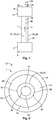
Fig. 1 shows a schematic drawing of a cable system with an exemplary embodiment of an inventive optical cable; and -
Fig. 2 shows a cross section of the exemplary embodiment of the inventive optical cable. - An
optical cable 1 according to the invention is shown inFig. 1 , wherein theoptical cable 1 connects twounits units optical cable 1 form a cable system 6. Theunit 2 may be aprocessing unit 8 for generating data and theunit 4 may be anoutput unit 10, such as a display and/or speaker system for outputting the data generated by theprocessing unit 8. Therefore, theoptical cable 1 transmits data in acable direction 12 from the processing unit to theoutput unit 10 through afirst channel 14. - The
first channel 14 is formed by at least one optical fiber 16 at acore section 18 of theoptical cable 1. In this exemplary embodiment, thecore section 18 is formed by a single optical fiber 16. However, in an alternative not shown embodiment, thecore section 18 may be formed by a bundle of optical fibers 16. Preferably, the optical fiber 16 is a glass optical fiber 20, which is capable of a high-speed transmission of signals and/or data. Thus, the information can be transmitted from theprocessing unit 8 to theoutput unit 10 at a high speed of up to about 40 Gbps. - The
output unit 10 may be an interactive unit working as aninterface 22, for auser 24 to send commands to theprocessing unit 8. Theinterface 22 may be controlled by at least one of a video, audio and touch event. For example, theinterface 22 may be a touch sensitive display transmitting information of at least one of position, pressure and motion to theprocessing unit 8. Additionally or alternatively, theinterface 22 may be voice controlled, wherein the user's audio commands are transmitted to theprocessing unit 8. The bandwidth required to transmit said information to theprocessing unit 8 is lower than the requirements for transmitting the signals and/or data from theprocessing unit 8 to theoutput unit 10. - For transmitting
user input 25 to theprocessing unit 8, a second channel needs to be provided. In known cable systems 6, a separateoptical cable 1 may be provided, each forming a single channel. However, this requires a lot of space since a separate connection port has to be provided at theunits - The function and structure of the inventive
optical cable 1 is now explained in greater detail with reference toFig. 2 showing across section 27 perpendicular to thecable direction 12 of the inventiveoptical cable 1. - In order to have an
optical cable 1 with a compact and cost efficient design, asecond channel 26 is formed by at least oneoptical fiber layer 28, surrounding thecore section 18. Thus, anoptical cable 1 with coaxially arranged channels is provided. The connection ports for each channel may also be consequently coaxially arranged, taking up less space than having two separate connection ports. - In this exemplary embodiment, the
first channel 14 forms aforward channel 30 and thesecond channel 26 forms abackward channel 32 transmitting signals and/or data in opposite directions. Therefore, a bidirectionaloptical cable 1 is produced. Thesecond channel 26 can be designed according to its requirements, independently from thefirst channel 14, preventing over-engineering of theoptical cable 1 and further decreasing the costs of theoptical cable 1. - The
core section 18 preferably comprises a glass optical fiber 20 with afiber core 34 and acladding 36 radially surrounding thefiber core 34. Thecladding 36 can further improve the transmission through thefiber core 34. Thecladding 36 may comprise multiple layers of different cladding materials and have a lower refractive index as thefiber core 34. Thecladding 36 causes light to be confined to thefiber core 34 by total internal reflection at the boundary between thecladding 36 and thefiber core 34. Hence, the light in thefirst channel 14 is prevented to pass through thecladding 36 and possibly cause an interference in the second channel. - Depending on the application requirements, the optical fiber 16 may be a single mode or multi-mode optical fiber. Single-mode optical fibers have the advantage that even at long distances, i.e. longer than about 100 m, a low signal and/or data loss can be achieved. Furthermore, a high bandwidth can be achieved even at a longer distance. Compared to single-mode optical fibers, a lower maximal bandwidth is possible with multi-mode optical fibers. However, multi-mode optical fibers may have its advantages in a simpler and low cost production. Furthermore, the termination of the optical fiber may be easier, since the fiber core diameter is larger. In particular, at short distances, multi-mode optical fibers can achieve a high bandwidth.
- The
second channel 26 is formed by the at least oneoptical fiber layer 28 that surrounds thecore section 18. In this exemplary embodiment, theoptical fiber layer 28 is in intimate contact with thecladding 36. Therefore, thecladding 36 also serves as aninner cladding 38 for thesecond channel 26. Theoptical fiber layer 28 and the optical fiber 16 may be attached rigidly to one another, preventing any relative movement between these two components. Theoptical fiber layer 28 and the optical fiber 16 may be bonded adhesively to one another. Alternatively, theoptical fiber layer 28 may be a separate part with a pipe shaped cross section, adapted to receive the optical fiber 16. The optical fiber 16 may be movable relatively to the pipe shapedoptical fiber layer 28, so that a damaged part can be removed and replaced, without affecting the other part. - The
optical fiber layer 28 may preferably comprise a polymeroptical fiber 40 such as PMMA. This may be of particular advantage since polymeroptical fibers 40 have proven to have a higher straining and bending tolerance than glass optical fibers and are cheaper. Since the transmission speed requirements of thesecond channel 26 are relatively low compared to thefirst channel 14 in this exemplary embodiment, the requirements can be satisfied by the polymeroptical fiber 40. - An
outer cladding 42 may be provided surrounding theoptical fiber layer 28, working as an outer boundary for containing the light waves and causing refraction. This further improves the transmission through theoptical fiber layer 28. Further components can be provided which are not shown in the figures. For example, a coating may be provided that surrounds the outer cladding, in order to reinforce theoptical fiber layer 28 and thefiber core 34. The coating may be a layer of plastic and may adsorb shocks as well as provide extra protection against excessive cable bends. Furthermore, a bundle of strengthening fibers may be provided, helping to protect theoptical fiber layer 28 and/or thefiber core 34 against crushing forces and excessive tension during installation. In addition, a cable jacket may be provided, sheathing the other components of theoptical cable 1. - With the inventive
optical cable 1, a compact and cost efficient design of anoptical cable 1 having multiple channels is provided. The bandwidth of each channel can be different, so that each channel can be optimized according to their respective application requirements. Thus, over-engineering of a channel is prevented. With the coaxial arrangement, a single optical cable can be used for different data and/or signal transmissions. -
- 1
- optical cable
- 2
- unit
- 4
- unit
- 6
- cable system
- 8
- processing unit
- 10
- output unit
- 12
- cable direction
- 14
- first channel
- 16
- optical fiber
- 18
- core section
- 20
- glass optical fiber
- 22
- interface
- 24
- user
- 25
- user input
- 26
- second channel
- 27
- cross section
- 28
- optical fiber layer
- 30
- forward channel
- 32
- backward channel
- 34
- fiber core
- 36
- cladding
- 38
- inner cladding
- 40
- polymer optical fiber
- 42
- outer cladding
Claims (15)
- Optical cable (1) comprising a core section (18) with at least one optical fiber (16) extending in a cable direction (12) forming a first channel (14) for transmitting signal and/or data, characterized in that the core section (18) is surrounded by at least one optical fiber layer (28) forming a second channel (26) for transmitting signal and/or data.
- Optical cable (1) according to claim 1, characterized in that a cladding (36) is provided between a fiber core (34) of the at least one optical fiber (16) and the at least one optical fiber layer (28).
- Optical cable (1) according to claim 1 or 2, characterized in that the first channel (14) has a different signal and/or data bandwidth than the second channel (26).
- Optical cable (1) according to claim 3, characterized in that the signal and/or data bandwidth of the second channel (26) is lower than the signal and/or data bandwidth of the first channel (14).
- Optical cable (1) according to any one of claims 1 to 4, characterized in that the first channel (14) and the second channel (26) transmit signal and/or data in opposite directions.
- Optical cable (1) according to any one of claims 1 to 5, characterized in that the at least one optical fiber (16) is a glass optical fiber (20).
- Optical cable (1) according to any one of claims 1 to 6, characterized in that the at least one optical fiber comprises a polymer optical fiber (40).
- Optical cable (1) according to any one of claims 1 to 7, characterized in that the at least one optical fiber layer (28) is arranged between an inner cladding (38) and an outer cladding (42).
- Optical cable (1) according to any one of claims 1 to 8, characterized in that the at least one optical fiber (16) and the at least one optical fiber layer (28) are rigidly attached to one another.
- Optical cable (1) according to any one of claims 1 to 9, characterized in that the at least one optical fiber (16) and the at least one optical fiber layer (28) are attached removably to one another.
- Optical cable (1) according to any one of claims 1 to 10, characterized in that the at least one optical fiber (16) is a single mode optical fiber (16).
- Optical cable (1) according to any one of claims 1 to 10, characterized in that the at least one optical fiber (16) is a multi mode optical fiber (16).
- Use of an optical cable (1) according to any one of claims 1 to 12 for transmitting at least one of a video, image and sound signal and/or data through the first channel (14).
- Use of an optical cable (1) according to any one of claims 1 to 12 for transmitting a user input signal and/or data through the second channel (26).
- Method for manufacturing an optical cable (1) comprising the step of surrounding a core section (18) comprising at least one optical fiber (16) extending in a cable direction (12) and forming a first channel (14) for transmitting signal and/or data with at least one optical fiber layer (28) forming a second channel (26) for transmitting signal and/or data.
Priority Applications (2)
| Application Number | Priority Date | Filing Date | Title |
|---|---|---|---|
| EP19152655.7A EP3683608B1 (en) | 2019-01-18 | 2019-01-18 | Optical cable |
| JP2020004120A JP7446819B2 (en) | 2019-01-18 | 2020-01-15 | optical cable |
Applications Claiming Priority (1)
| Application Number | Priority Date | Filing Date | Title |
|---|---|---|---|
| EP19152655.7A EP3683608B1 (en) | 2019-01-18 | 2019-01-18 | Optical cable |
Publications (2)
| Publication Number | Publication Date |
|---|---|
| EP3683608A1 true EP3683608A1 (en) | 2020-07-22 |
| EP3683608B1 EP3683608B1 (en) | 2025-03-26 |
Family
ID=65138827
Family Applications (1)
| Application Number | Title | Priority Date | Filing Date |
|---|---|---|---|
| EP19152655.7A Active EP3683608B1 (en) | 2019-01-18 | 2019-01-18 | Optical cable |
Country Status (2)
| Country | Link |
|---|---|
| EP (1) | EP3683608B1 (en) |
| JP (1) | JP7446819B2 (en) |
Families Citing this family (1)
| Publication number | Priority date | Publication date | Assignee | Title |
|---|---|---|---|---|
| CN117062652A (en) * | 2021-03-30 | 2023-11-14 | 古河电气工业株式会社 | Optical transmitting and receiving probe system and optical transmitting and receiving probe |
Citations (4)
| Publication number | Priority date | Publication date | Assignee | Title |
|---|---|---|---|---|
| GB2136239A (en) * | 1983-03-03 | 1984-09-12 | British Telecomm | Optical fibre transmission systems |
| US5627934A (en) * | 1994-08-03 | 1997-05-06 | Martin Marietta Energy Systems, Inc. | Concentric core optical fiber with multiple-mode signal transmission |
| US6553166B1 (en) * | 2000-09-20 | 2003-04-22 | Lsi Logic Corporation | Concentric optical cable with full duplex connectors |
| US20090238233A1 (en) * | 2008-03-20 | 2009-09-24 | Omar Bchir | Optical die structures and associated package substrates |
Family Cites Families (3)
| Publication number | Priority date | Publication date | Assignee | Title |
|---|---|---|---|---|
| JPS60221706A (en) * | 1985-03-29 | 1985-11-06 | Hitachi Ltd | optical fiber |
| JP3521326B2 (en) * | 1999-12-07 | 2004-04-19 | 株式会社日立製作所 | Optical fiber, optical receiving device and optical transmitting device |
| JP7128213B2 (en) | 2017-06-02 | 2022-08-30 | コムスコープ テクノロジーズ リミティド ライアビリティ カンパニー | Concentric circular fiber for space division multiplexing optical communication and method of using the same |
-
2019
- 2019-01-18 EP EP19152655.7A patent/EP3683608B1/en active Active
-
2020
- 2020-01-15 JP JP2020004120A patent/JP7446819B2/en active Active
Patent Citations (4)
| Publication number | Priority date | Publication date | Assignee | Title |
|---|---|---|---|---|
| GB2136239A (en) * | 1983-03-03 | 1984-09-12 | British Telecomm | Optical fibre transmission systems |
| US5627934A (en) * | 1994-08-03 | 1997-05-06 | Martin Marietta Energy Systems, Inc. | Concentric core optical fiber with multiple-mode signal transmission |
| US6553166B1 (en) * | 2000-09-20 | 2003-04-22 | Lsi Logic Corporation | Concentric optical cable with full duplex connectors |
| US20090238233A1 (en) * | 2008-03-20 | 2009-09-24 | Omar Bchir | Optical die structures and associated package substrates |
Also Published As
| Publication number | Publication date |
|---|---|
| EP3683608B1 (en) | 2025-03-26 |
| JP7446819B2 (en) | 2024-03-11 |
| JP2020118966A (en) | 2020-08-06 |
Similar Documents
| Publication | Publication Date | Title |
|---|---|---|
| US10139559B2 (en) | Multi-core optical fiber, optical cable, and optical connector | |
| JP6183357B2 (en) | Multi-core optical fiber, multi-core optical fiber cable, and multi-core optical fiber transmission system | |
| EP2946238B1 (en) | Fiber optic ribbon cable | |
| US20150309274A1 (en) | Fiber optic ribbon cable | |
| US12130469B2 (en) | Hollow-core fiber cable and method of manufacturing the same | |
| JP7660655B2 (en) | Optical input/output device | |
| Hayashi et al. | Multi-core fibers for data center applications | |
| WO2017217539A1 (en) | Method for axial alignment of coupled multicore optical fiber | |
| EP3812815B1 (en) | Optical fiber cable | |
| CN111007590A (en) | Weakly coupled few-mode optical fiber for mode division multiplexing and corresponding optical transmission system | |
| EP3683608B1 (en) | Optical cable | |
| Sasaki et al. | Variations in the Optical Characteristics of 200 μm and 250 μm Coated Multicore Fibres Owing to Cabling | |
| TW535014B (en) | Optical-fiber cable and method for transmitting optical signals | |
| GB2565128A (en) | Fan-in/Fan-out device | |
| CN219997338U (en) | Optical fiber and optical fiber communication system | |
| EP4579304A1 (en) | Optical fiber cable with multifibre tight-buffered unit | |
| WO2026100077A1 (en) | Optical fiber cable | |
| JP6925894B2 (en) | Optical equipment, communication system and combine / demultiplexing method | |
| JP2025163997A (en) | Few-mode multi-core optical fiber and optical transmission system | |
| CN106125228A (en) | A kind of easily branched optical cable | |
| CN121299864A (en) | A space-division multiplexing multi-core optical fiber cable for backbone networks | |
| WO2026040340A1 (en) | Multicore fiber, optical cable, and communication system | |
| EP2717077B1 (en) | Coaxial optical fiber with subwavelength core | |
| JP2014216964A (en) | Optical cable unit, optical transmission system and connection method | |
| JP2022109739A (en) | Asymmetric bidirectional optical transmission module |
Legal Events
| Date | Code | Title | Description |
|---|---|---|---|
| PUAI | Public reference made under article 153(3) epc to a published international application that has entered the european phase |
Free format text: ORIGINAL CODE: 0009012 |
|
| STAA | Information on the status of an ep patent application or granted ep patent |
Free format text: STATUS: THE APPLICATION HAS BEEN PUBLISHED |
|
| AK | Designated contracting states |
Kind code of ref document: A1 Designated state(s): AL AT BE BG CH CY CZ DE DK EE ES FI FR GB GR HR HU IE IS IT LI LT LU LV MC MK MT NL NO PL PT RO RS SE SI SK SM TR |
|
| AX | Request for extension of the european patent |
Extension state: BA ME |
|
| STAA | Information on the status of an ep patent application or granted ep patent |
Free format text: STATUS: REQUEST FOR EXAMINATION WAS MADE |
|
| 17P | Request for examination filed |
Effective date: 20210119 |
|
| RBV | Designated contracting states (corrected) |
Designated state(s): AL AT BE BG CH CY CZ DE DK EE ES FI FR GB GR HR HU IE IS IT LI LT LU LV MC MK MT NL NO PL PT RO RS SE SI SK SM TR |
|
| STAA | Information on the status of an ep patent application or granted ep patent |
Free format text: STATUS: EXAMINATION IS IN PROGRESS |
|
| 17Q | First examination report despatched |
Effective date: 20221221 |
|
| REG | Reference to a national code |
Ref country code: DE Ref legal event code: R079 Free format text: PREVIOUS MAIN CLASS: G02B0006020000 Ipc: G02B0006440000 Ref document number: 602019067672 Country of ref document: DE |
|
| GRAP | Despatch of communication of intention to grant a patent |
Free format text: ORIGINAL CODE: EPIDOSNIGR1 |
|
| STAA | Information on the status of an ep patent application or granted ep patent |
Free format text: STATUS: GRANT OF PATENT IS INTENDED |
|
| RIC1 | Information provided on ipc code assigned before grant |
Ipc: G02B 6/02 20060101ALI20241107BHEP Ipc: G02B 6/44 20060101AFI20241107BHEP |
|
| INTG | Intention to grant announced |
Effective date: 20241125 |
|
| GRAS | Grant fee paid |
Free format text: ORIGINAL CODE: EPIDOSNIGR3 |
|
| GRAA | (expected) grant |
Free format text: ORIGINAL CODE: 0009210 |
|
| STAA | Information on the status of an ep patent application or granted ep patent |
Free format text: STATUS: THE PATENT HAS BEEN GRANTED |
|
| AK | Designated contracting states |
Kind code of ref document: B1 Designated state(s): AL AT BE BG CH CY CZ DE DK EE ES FI FR GB GR HR HU IE IS IT LI LT LU LV MC MK MT NL NO PL PT RO RS SE SI SK SM TR |
|
| REG | Reference to a national code |
Ref country code: GB Ref legal event code: FG4D |
|
| REG | Reference to a national code |
Ref country code: CH Ref legal event code: EP |
|
| REG | Reference to a national code |
Ref country code: DE Ref legal event code: R096 Ref document number: 602019067672 Country of ref document: DE |
|
| REG | Reference to a national code |
Ref country code: IE Ref legal event code: FG4D |
|
| PG25 | Lapsed in a contracting state [announced via postgrant information from national office to epo] |
Ref country code: RS Free format text: LAPSE BECAUSE OF FAILURE TO SUBMIT A TRANSLATION OF THE DESCRIPTION OR TO PAY THE FEE WITHIN THE PRESCRIBED TIME-LIMIT Effective date: 20250626 |
|
| PG25 | Lapsed in a contracting state [announced via postgrant information from national office to epo] |
Ref country code: FI Free format text: LAPSE BECAUSE OF FAILURE TO SUBMIT A TRANSLATION OF THE DESCRIPTION OR TO PAY THE FEE WITHIN THE PRESCRIBED TIME-LIMIT Effective date: 20250326 |
|
| REG | Reference to a national code |
Ref country code: LT Ref legal event code: MG9D |
|
| PG25 | Lapsed in a contracting state [announced via postgrant information from national office to epo] |
Ref country code: NO Free format text: LAPSE BECAUSE OF FAILURE TO SUBMIT A TRANSLATION OF THE DESCRIPTION OR TO PAY THE FEE WITHIN THE PRESCRIBED TIME-LIMIT Effective date: 20250626 |
|
| PG25 | Lapsed in a contracting state [announced via postgrant information from national office to epo] |
Ref country code: HR Free format text: LAPSE BECAUSE OF FAILURE TO SUBMIT A TRANSLATION OF THE DESCRIPTION OR TO PAY THE FEE WITHIN THE PRESCRIBED TIME-LIMIT Effective date: 20250326 |
|
| PG25 | Lapsed in a contracting state [announced via postgrant information from national office to epo] |
Ref country code: LV Free format text: LAPSE BECAUSE OF FAILURE TO SUBMIT A TRANSLATION OF THE DESCRIPTION OR TO PAY THE FEE WITHIN THE PRESCRIBED TIME-LIMIT Effective date: 20250326 |
|
| PG25 | Lapsed in a contracting state [announced via postgrant information from national office to epo] |
Ref country code: GR Free format text: LAPSE BECAUSE OF FAILURE TO SUBMIT A TRANSLATION OF THE DESCRIPTION OR TO PAY THE FEE WITHIN THE PRESCRIBED TIME-LIMIT Effective date: 20250627 Ref country code: BG Free format text: LAPSE BECAUSE OF FAILURE TO SUBMIT A TRANSLATION OF THE DESCRIPTION OR TO PAY THE FEE WITHIN THE PRESCRIBED TIME-LIMIT Effective date: 20250326 |
|
| REG | Reference to a national code |
Ref country code: NL Ref legal event code: MP Effective date: 20250326 |
|
| PG25 | Lapsed in a contracting state [announced via postgrant information from national office to epo] |
Ref country code: NL Free format text: LAPSE BECAUSE OF FAILURE TO SUBMIT A TRANSLATION OF THE DESCRIPTION OR TO PAY THE FEE WITHIN THE PRESCRIBED TIME-LIMIT Effective date: 20250326 |
|
| PG25 | Lapsed in a contracting state [announced via postgrant information from national office to epo] |
Ref country code: SE Free format text: LAPSE BECAUSE OF FAILURE TO SUBMIT A TRANSLATION OF THE DESCRIPTION OR TO PAY THE FEE WITHIN THE PRESCRIBED TIME-LIMIT Effective date: 20250326 |
|
| REG | Reference to a national code |
Ref country code: AT Ref legal event code: MK05 Ref document number: 1779490 Country of ref document: AT Kind code of ref document: T Effective date: 20250326 |
|
| PG25 | Lapsed in a contracting state [announced via postgrant information from national office to epo] |
Ref country code: SM Free format text: LAPSE BECAUSE OF FAILURE TO SUBMIT A TRANSLATION OF THE DESCRIPTION OR TO PAY THE FEE WITHIN THE PRESCRIBED TIME-LIMIT Effective date: 20250326 |
|
| PG25 | Lapsed in a contracting state [announced via postgrant information from national office to epo] |
Ref country code: PT Free format text: LAPSE BECAUSE OF FAILURE TO SUBMIT A TRANSLATION OF THE DESCRIPTION OR TO PAY THE FEE WITHIN THE PRESCRIBED TIME-LIMIT Effective date: 20250728 Ref country code: ES Free format text: LAPSE BECAUSE OF FAILURE TO SUBMIT A TRANSLATION OF THE DESCRIPTION OR TO PAY THE FEE WITHIN THE PRESCRIBED TIME-LIMIT Effective date: 20250326 |
|
| PG25 | Lapsed in a contracting state [announced via postgrant information from national office to epo] |
Ref country code: PL Free format text: LAPSE BECAUSE OF FAILURE TO SUBMIT A TRANSLATION OF THE DESCRIPTION OR TO PAY THE FEE WITHIN THE PRESCRIBED TIME-LIMIT Effective date: 20250326 Ref country code: IT Free format text: LAPSE BECAUSE OF FAILURE TO SUBMIT A TRANSLATION OF THE DESCRIPTION OR TO PAY THE FEE WITHIN THE PRESCRIBED TIME-LIMIT Effective date: 20250326 |
|
| PG25 | Lapsed in a contracting state [announced via postgrant information from national office to epo] |
Ref country code: AT Free format text: LAPSE BECAUSE OF FAILURE TO SUBMIT A TRANSLATION OF THE DESCRIPTION OR TO PAY THE FEE WITHIN THE PRESCRIBED TIME-LIMIT Effective date: 20250326 |
|
| PG25 | Lapsed in a contracting state [announced via postgrant information from national office to epo] |
Ref country code: EE Free format text: LAPSE BECAUSE OF FAILURE TO SUBMIT A TRANSLATION OF THE DESCRIPTION OR TO PAY THE FEE WITHIN THE PRESCRIBED TIME-LIMIT Effective date: 20250326 |
|
| PG25 | Lapsed in a contracting state [announced via postgrant information from national office to epo] |
Ref country code: RO Free format text: LAPSE BECAUSE OF FAILURE TO SUBMIT A TRANSLATION OF THE DESCRIPTION OR TO PAY THE FEE WITHIN THE PRESCRIBED TIME-LIMIT Effective date: 20250326 |
|
| PG25 | Lapsed in a contracting state [announced via postgrant information from national office to epo] |
Ref country code: SK Free format text: LAPSE BECAUSE OF FAILURE TO SUBMIT A TRANSLATION OF THE DESCRIPTION OR TO PAY THE FEE WITHIN THE PRESCRIBED TIME-LIMIT Effective date: 20250326 |
|
| PG25 | Lapsed in a contracting state [announced via postgrant information from national office to epo] |
Ref country code: IS Free format text: LAPSE BECAUSE OF FAILURE TO SUBMIT A TRANSLATION OF THE DESCRIPTION OR TO PAY THE FEE WITHIN THE PRESCRIBED TIME-LIMIT Effective date: 20250726 |
|
| REG | Reference to a national code |
Ref country code: DE Ref legal event code: R097 Ref document number: 602019067672 Country of ref document: DE |
|
| PG25 | Lapsed in a contracting state [announced via postgrant information from national office to epo] |
Ref country code: DK Free format text: LAPSE BECAUSE OF FAILURE TO SUBMIT A TRANSLATION OF THE DESCRIPTION OR TO PAY THE FEE WITHIN THE PRESCRIBED TIME-LIMIT Effective date: 20250326 |
|
| PG25 | Lapsed in a contracting state [announced via postgrant information from national office to epo] |
Ref country code: CZ Free format text: LAPSE BECAUSE OF FAILURE TO SUBMIT A TRANSLATION OF THE DESCRIPTION OR TO PAY THE FEE WITHIN THE PRESCRIBED TIME-LIMIT Effective date: 20250326 |
|
| PLBE | No opposition filed within time limit |
Free format text: ORIGINAL CODE: 0009261 |
|
| STAA | Information on the status of an ep patent application or granted ep patent |
Free format text: STATUS: NO OPPOSITION FILED WITHIN TIME LIMIT |
|
| REG | Reference to a national code |
Ref country code: CH Ref legal event code: L10 Free format text: ST27 STATUS EVENT CODE: U-0-0-L10-L00 (AS PROVIDED BY THE NATIONAL OFFICE) Effective date: 20260211 |
|
| 26N | No opposition filed |
Effective date: 20260105 |
|
| PGFP | Annual fee paid to national office [announced via postgrant information from national office to epo] |
Ref country code: DE Payment date: 20251203 Year of fee payment: 8 |