EP3683467A1 - Zuspanneinrichtung für eine scheibenbremse von nutzfahrzeugen und eine scheibenbremse für nutzfahrzeuge - Google Patents
Zuspanneinrichtung für eine scheibenbremse von nutzfahrzeugen und eine scheibenbremse für nutzfahrzeuge Download PDFInfo
- Publication number
- EP3683467A1 EP3683467A1 EP19152037.8A EP19152037A EP3683467A1 EP 3683467 A1 EP3683467 A1 EP 3683467A1 EP 19152037 A EP19152037 A EP 19152037A EP 3683467 A1 EP3683467 A1 EP 3683467A1
- Authority
- EP
- European Patent Office
- Prior art keywords
- pressure plate
- heat protection
- protection shield
- plate head
- brake
- Prior art date
- Legal status (The legal status is an assumption and is not a legal conclusion. Google has not performed a legal analysis and makes no representation as to the accuracy of the status listed.)
- Granted
Links
Images




Classifications
-
- F—MECHANICAL ENGINEERING; LIGHTING; HEATING; WEAPONS; BLASTING
- F16—ENGINEERING ELEMENTS AND UNITS; GENERAL MEASURES FOR PRODUCING AND MAINTAINING EFFECTIVE FUNCTIONING OF MACHINES OR INSTALLATIONS; THERMAL INSULATION IN GENERAL
- F16D—COUPLINGS FOR TRANSMITTING ROTATION; CLUTCHES; BRAKES
- F16D65/00—Parts or details
- F16D65/14—Actuating mechanisms for brakes; Means for initiating operation at a predetermined position
- F16D65/16—Actuating mechanisms for brakes; Means for initiating operation at a predetermined position arranged in or on the brake
- F16D65/18—Actuating mechanisms for brakes; Means for initiating operation at a predetermined position arranged in or on the brake adapted for drawing members together, e.g. for disc brakes
- F16D65/183—Actuating mechanisms for brakes; Means for initiating operation at a predetermined position arranged in or on the brake adapted for drawing members together, e.g. for disc brakes with force-transmitting members arranged side by side acting on a spot type force-applying member
-
- F—MECHANICAL ENGINEERING; LIGHTING; HEATING; WEAPONS; BLASTING
- F16—ENGINEERING ELEMENTS AND UNITS; GENERAL MEASURES FOR PRODUCING AND MAINTAINING EFFECTIVE FUNCTIONING OF MACHINES OR INSTALLATIONS; THERMAL INSULATION IN GENERAL
- F16D—COUPLINGS FOR TRANSMITTING ROTATION; CLUTCHES; BRAKES
- F16D65/00—Parts or details
- F16D65/78—Features relating to cooling
- F16D65/84—Features relating to cooling for disc brakes
-
- B—PERFORMING OPERATIONS; TRANSPORTING
- B60—VEHICLES IN GENERAL
- B60T—VEHICLE BRAKE CONTROL SYSTEMS OR PARTS THEREOF; BRAKE CONTROL SYSTEMS OR PARTS THEREOF, IN GENERAL; ARRANGEMENT OF BRAKING ELEMENTS ON VEHICLES IN GENERAL; PORTABLE DEVICES FOR PREVENTING UNWANTED MOVEMENT OF VEHICLES; VEHICLE MODIFICATIONS TO FACILITATE COOLING OF BRAKES
- B60T1/00—Arrangements of braking elements, i.e. of those parts where braking effect occurs specially for vehicles
- B60T1/02—Arrangements of braking elements, i.e. of those parts where braking effect occurs specially for vehicles acting by retarding wheels
- B60T1/06—Arrangements of braking elements, i.e. of those parts where braking effect occurs specially for vehicles acting by retarding wheels acting otherwise than on tread, e.g. employing rim, drum, disc, or transmission or on double wheels
- B60T1/065—Arrangements of braking elements, i.e. of those parts where braking effect occurs specially for vehicles acting by retarding wheels acting otherwise than on tread, e.g. employing rim, drum, disc, or transmission or on double wheels employing disc
-
- F—MECHANICAL ENGINEERING; LIGHTING; HEATING; WEAPONS; BLASTING
- F16—ENGINEERING ELEMENTS AND UNITS; GENERAL MEASURES FOR PRODUCING AND MAINTAINING EFFECTIVE FUNCTIONING OF MACHINES OR INSTALLATIONS; THERMAL INSULATION IN GENERAL
- F16D—COUPLINGS FOR TRANSMITTING ROTATION; CLUTCHES; BRAKES
- F16D55/00—Brakes with substantially-radial braking surfaces pressed together in axial direction, e.g. disc brakes
- F16D55/02—Brakes with substantially-radial braking surfaces pressed together in axial direction, e.g. disc brakes with axially-movable discs or pads pressed against axially-located rotating members
- F16D55/22—Brakes with substantially-radial braking surfaces pressed together in axial direction, e.g. disc brakes with axially-movable discs or pads pressed against axially-located rotating members by clamping an axially-located rotating disc between movable braking members, e.g. movable brake discs or brake pads
- F16D55/224—Brakes with substantially-radial braking surfaces pressed together in axial direction, e.g. disc brakes with axially-movable discs or pads pressed against axially-located rotating members by clamping an axially-located rotating disc between movable braking members, e.g. movable brake discs or brake pads with a common actuating member for the braking members
- F16D55/225—Brakes with substantially-radial braking surfaces pressed together in axial direction, e.g. disc brakes with axially-movable discs or pads pressed against axially-located rotating members by clamping an axially-located rotating disc between movable braking members, e.g. movable brake discs or brake pads with a common actuating member for the braking members the braking members being brake pads
-
- F—MECHANICAL ENGINEERING; LIGHTING; HEATING; WEAPONS; BLASTING
- F16—ENGINEERING ELEMENTS AND UNITS; GENERAL MEASURES FOR PRODUCING AND MAINTAINING EFFECTIVE FUNCTIONING OF MACHINES OR INSTALLATIONS; THERMAL INSULATION IN GENERAL
- F16D—COUPLINGS FOR TRANSMITTING ROTATION; CLUTCHES; BRAKES
- F16D55/00—Brakes with substantially-radial braking surfaces pressed together in axial direction, e.g. disc brakes
- F16D55/02—Brakes with substantially-radial braking surfaces pressed together in axial direction, e.g. disc brakes with axially-movable discs or pads pressed against axially-located rotating members
- F16D55/22—Brakes with substantially-radial braking surfaces pressed together in axial direction, e.g. disc brakes with axially-movable discs or pads pressed against axially-located rotating members by clamping an axially-located rotating disc between movable braking members, e.g. movable brake discs or brake pads
- F16D55/224—Brakes with substantially-radial braking surfaces pressed together in axial direction, e.g. disc brakes with axially-movable discs or pads pressed against axially-located rotating members by clamping an axially-located rotating disc between movable braking members, e.g. movable brake discs or brake pads with a common actuating member for the braking members
- F16D55/225—Brakes with substantially-radial braking surfaces pressed together in axial direction, e.g. disc brakes with axially-movable discs or pads pressed against axially-located rotating members by clamping an axially-located rotating disc between movable braking members, e.g. movable brake discs or brake pads with a common actuating member for the braking members the braking members being brake pads
- F16D55/226—Brakes with substantially-radial braking surfaces pressed together in axial direction, e.g. disc brakes with axially-movable discs or pads pressed against axially-located rotating members by clamping an axially-located rotating disc between movable braking members, e.g. movable brake discs or brake pads with a common actuating member for the braking members the braking members being brake pads in which the common actuating member is moved axially, e.g. floating caliper disc brakes
-
- F—MECHANICAL ENGINEERING; LIGHTING; HEATING; WEAPONS; BLASTING
- F16—ENGINEERING ELEMENTS AND UNITS; GENERAL MEASURES FOR PRODUCING AND MAINTAINING EFFECTIVE FUNCTIONING OF MACHINES OR INSTALLATIONS; THERMAL INSULATION IN GENERAL
- F16D—COUPLINGS FOR TRANSMITTING ROTATION; CLUTCHES; BRAKES
- F16D65/00—Parts or details
- F16D65/14—Actuating mechanisms for brakes; Means for initiating operation at a predetermined position
- F16D65/16—Actuating mechanisms for brakes; Means for initiating operation at a predetermined position arranged in or on the brake
- F16D65/18—Actuating mechanisms for brakes; Means for initiating operation at a predetermined position arranged in or on the brake adapted for drawing members together, e.g. for disc brakes
-
- F—MECHANICAL ENGINEERING; LIGHTING; HEATING; WEAPONS; BLASTING
- F16—ENGINEERING ELEMENTS AND UNITS; GENERAL MEASURES FOR PRODUCING AND MAINTAINING EFFECTIVE FUNCTIONING OF MACHINES OR INSTALLATIONS; THERMAL INSULATION IN GENERAL
- F16D—COUPLINGS FOR TRANSMITTING ROTATION; CLUTCHES; BRAKES
- F16D65/00—Parts or details
- F16D65/78—Features relating to cooling
- F16D2065/785—Heat insulation or reflection
-
- F—MECHANICAL ENGINEERING; LIGHTING; HEATING; WEAPONS; BLASTING
- F16—ENGINEERING ELEMENTS AND UNITS; GENERAL MEASURES FOR PRODUCING AND MAINTAINING EFFECTIVE FUNCTIONING OF MACHINES OR INSTALLATIONS; THERMAL INSULATION IN GENERAL
- F16D—COUPLINGS FOR TRANSMITTING ROTATION; CLUTCHES; BRAKES
- F16D2125/00—Components of actuators
- F16D2125/18—Mechanical mechanisms
- F16D2125/20—Mechanical mechanisms converting rotation to linear movement or vice versa
- F16D2125/34—Mechanical mechanisms converting rotation to linear movement or vice versa acting in the direction of the axis of rotation
- F16D2125/40—Screw-and-nut
Definitions
- the invention relates to an application device for disc brakes of commercial vehicles and a disc brake for commercial vehicles.
- Disc brakes and their construction are well known in the commercial vehicle sector. Sliding caliper disc brakes are preferred today.
- a brake disc of the disc brake is applied via an application device.
- a force provided via a brake cylinder is transmitted to the application device via a rotary lever arranged in the disc brake.
- An adjusting spindle arranged axially in the direction of the brake disk transmits the application force via a pressure piece to an application-side brake pad, the application-side brake pad and the rim-side brake pad tightening the brake disk.
- the disc brake is divided into a rim side and an application side. The side of the disc brake is defined under an application side, on which the brake disc is applied via an application device.
- the side of the disc brake directed in the direction of the rim of a vehicle is defined as the rim side.
- a bellows is arranged between a pressure plate of the adjusting spindle and the opening for the adjusting spindle.
- the bellows connects the pressure plate of the adjusting spindle with the brake caliper.
- the bellows with the adjusting spindle moves axially in the direction of the brake disc or, after a braking process, axially opposite the brake disc.
- the brake pads are in contact with the brake disc and generate heat in the area of the bellows through friction.
- the actuation of the brake cylinder and the heat generated during the braking process creates overpressure in the brake caliper and in an application box, as a result of which the bellows inflates, attaches itself to the back of the pressure plate, which is opposite the brake disc, and sticks due to the high temperatures.
- the application box includes an application device, an adjustment device and a pressure piece. After cooling, the bellows often develop cracks.
- the DE102007059777B4 solves the problem of inflation and sticking of the bellows on the pressure plate by making the bellows from a high temperature material.
- the high-temperature material has a low crack resistance and a short service life.
- high-temperature material is very costly to purchase.
- the DE102008054162A1 discloses, for example, a heat protection shield defined as an insulating shield, which bears completely or at least largely over the full area on the pressure plate of the adjusting spindle.
- the disadvantage is that the heat, starting from the brake disc, is transferred directly to the heat protection shield.
- These heat protection shields are also made of a high-temperature resistant material, which means that the heat protection shield forms cracks prematurely and the heat protection shield has to be replaced above average for safety reasons.
- the object of the invention is to provide a heat shield for an application device and a disc brake for commercial vehicles, which overcomes the disadvantages of the aforementioned prior art.
- a heat protection shield is arranged in an application device of a disc brake between a pressure plate head, an adjusting spindle and a bellows, the heat protection shield being arranged at a distance X between the pressure plate head and the heat protection shield.
- the heat protection shield is not fully arranged on the back of the pressure plate. In other words, the heat protection shield is not arranged over the full area on the side of a pressure plate facing away from the brake disc.
- the distance to the heat shield prevents the heat shield from sticking to the pressure plate head. This means that the distance between the heat transfer of the brake disc between the pressure plate and the heat shield is interrupted.
- Another advantage of the distance between the heat shield and the pressure plate is that high-temperature material for the heat shield can be dispensed with.
- the application device between the pressure plate and the heat shield has an insulating layer.
- the insulating layer interrupts the heat transfer, starting from the brake disc in the direction of the bellows, which is why the side of the heat shield facing away from the brake disc cools and the surface temperature on the heat shield is lower than the surface temperature on the heat shield without an insulation layer.
- the heat protection shield is a metal ring coated with an elastomer or a metal ring coated with an elastomer Metal ring.
- the base of the heat shield is a ring made of metal.
- the metal ring stabilizes the heat shield and holds the heat shield in place on the adjusting spindle.
- an elastomer encases the metal ring. Polymers that coat the metal ring are also conceivable.
- the elastomer absorbs the radiant heat from the brake disc and protects the bellows from sticking or, in other words, from welding the metal ring to the pressure plate by the radiant heat from the brake disc. It is also conceivable to spray the elastomer onto the metal ring.
- the heat protection shield has the task of protecting the bellows against sticking to the pressure plate of the adjusting spindle.
- the metal ring is only coated on one side with the elastomer in order to reduce costs. If the metal ring is coated on one side, the side of the metal ring facing the bellows must be coated so that the bellows does not stick to the metal ring and forms cracks after the metal ring has cooled.
- the metal ring is coated on one side, with the side of the metal ring facing away from the bellows, with the elastomer, so that the temperature of the heat protection shield is kept lower.
- the heat protection shield is formed from plastic or silicone in a further embodiment. Both the ring for the shape and stability of the heat shield, as well as the sheathing or the coating are completely made of plastic or silicone. It is conceivable to produce the heat protection shield from a single plastic or from several plastics.
- the heat protection shield is advantageously arranged on the pressure plate or the pressure plate head with an arrangement comprising a press fit or a free position.
- the connection of the heat protection shield to the pressure plate is defined as a press fit, in which, after the heat protection shield has been arranged on the pressure plate, a press fit is created and longitudinal and transverse forces are transmitted in a force-locking manner.
- the heat protection shield can no longer move axially along the adjusting spindle.
- the heat shield can move almost freely axially along the pressure plate or the heat shield preferably has an axial play of 0.1 mm to 3 mm, more preferably of 0.1 mm to 1 mm.
- the heat shield is only restricted by the end collar of the bellows.
- the insulating layer is an air layer.
- Air has a very low coefficient of thermal conductivity of 0.024 [W / (m * K)] compared to other substances, substance mixtures or solids. Due to the low thermal conductivity of the air, the high temperature in the disc brake, formed by the radiated heat of the brake disc, is significantly reduced before the heat protection shield is reached.
- the heat protection shield is designed as an O-ring. Both the pressure plate and the bellows have a circular geometry, so that the heat shield covers the bellows over the entire surface or at least partially against sticking to the pressure plate head. Furthermore, the heat shield designed as an O-ring can be centered or positioned on the pressure plate head. In particular, the distance between the pressure plate head and the heat shield in a further embodiment is greater than or equal to 1 mm. The distance is necessary for the arrangement or filling of an additional insulation layer. The temperature also decreases with increasing distance from the brake disc. In addition, the tolerance range can be adhered to in assembly from a distance greater than or equal to 1 mm between the pressure plate head and the heat protection shield.
- the heat shield based on the pressure plate head, is arranged parallel or obliquely between the pressure plate head and the bellows in a further embodiment.
- the heat protection plate can be arranged obliquely or parallel to the pressure plate head, as a result of which a uniform distance, and therefore a uniform insulating layer, is achieved between the heat protection plate and the pressure plate head.
- the uniform insulating layer has the advantage that the heat transfer on the entire surface or at least predominantly on the entire surface of the heat protection shield is the same.
- the heat shield also has pins or grooves in the direction of the pressure plate head.
- the pins of the heat protection shield are designed to engage in grooves in the pressure plate head. Furthermore, the pins of the pressure plate head can engage in the grooves of the heat protection shield.
- the heat protection shield is also connected to the pressure plate, in particular to the pressure plate head, in a rotationally secure manner with the pins. In addition, with the pin arrangement on the heat shield, the bellows is evenly protected from the effects of heat, starting from the brake disc and the brake pads.
- the heat protection shield has at least 3 pins and the pressure plate head has at least 3 grooves.
- the pins of the heat shield and the grooves of the pressure plate head are advantageously arranged geometrically as a triangular shape and secure the heat shield against an axial rotation.
- the free space between the pins of the heat shield enables air movement and / or convection, as a result of which heat build-up between the pressure plate head and the heat shield is avoided.
- the axial rotation of the heat shield does not have to be completely prevented.
- the heat protection shield can have an axial play, the grooves of the pressure plate head being larger in size than the pins of the heat protection shield.
- the grooves of the pressure plate head and the pins of the heat shield are designed as a press fit for positioning the heat shield on the pressure plate head.
- the heat protection shield particularly advantageously has 6 pins and the pressure plate head has 6 grooves.
- the heat protection shield can be supported particularly securely on the pressure plate head.
- a circumferential pin is arranged on the heat protection shield and engages in a circumferential groove of the pressure plate head. Advantages of the circumferential shoulder of the heat protection shield arise in the assembly, since the circumferential shoulder of the pressure plate head can be installed in the circumferential groove of the pressure plate head without further rotation of the pressure plate head.
- the pins of the heat shield are arranged radially on the outside of the heat shield with respect to a pressure plate axis.
- the heat shield is easy by machine processes such as stamping and forming processes or by turning processes. An additional attachment of the pins to the heat protection shield is not necessary.
- the heat shield has knobs in the direction of the pressure plate head.
- the knobs of the pressure plate head serve to support the heat protection shield on the pressure plate head.
- the pressure plate head can have nubs in the direction of the heat protection plate in order to support the heat protection shield on the pressure plate head.
- the geometry of the knobs can be different and, for example, they can have the shape of a rectangle, square, triangle or circle.
- the pressure plate head or the heat protection plate has an even number of knobs so that the pressure plate head lies evenly on the heat protection plate or the heat protection plate lies evenly on the pressure plate head.
- the knobs are components of the elastomer of the heat protection shield.
- the knobs are molded from the elastomer.
- the knobs can also be molded onto the elastomer.
- the pressure plate head in a further embodiment has support elements in the direction of the application side of the disc brake.
- the support elements are geometric elevations on which the heat protection shield is supported, wherein a full-surface support of the heat protection shield on the pressure plate head is avoided.
- the support elements can vary in shape. Additional costs do not arise because the support elements are formed simultaneously with the pressure plate or the pressure plate head, during the manufacturing process, comprising stamping or casting, the pressure plate or only the pressure plate head.
- the object is achieved in a last advantageous embodiment by a disc brake for motor vehicles, the disc brake having an application device according to one of the preceding embodiments.
- Fig. 1 shows a side sectional view of a disc brake 2 with an application device 1.
- the disc brake 2 has an application side ZS and a rim side FS.
- a brake carrier 11 has on the rim side FS a lining carrier shaft 12 for receiving a brake lining 14 and on the application side ZS a lining carrier shaft 13 for receiving a brake lining 15.
- Hold-down springs 17, 18 and a pad retainer 19 secure the brake pads 14, 15 against radial falling out of the brake pad carrier shafts 12, 13.
- the application device 1 has a rotary lever 20 which, during an application process, axially displaces an adjusting spindle 3 having a pressure plate 4 along an axial axis A in the direction of the brake linings 14, 15, as a result of which the brake linings 14, 15 against one Brake disc, not shown, can be pressed.
- the pressure plate 4 has a circumferential groove 6, in which a bellows 5 is arranged.
- the bellows 5 is additionally connected to a brake caliper 16 by a cover and protects the application device 1 against environmental influences such as dust, sand, stones or snow.
- a heat shield 7 is arranged between the bellows 5 and a pressure plate head 4a of the pressure plate 4.
- the heat shield 7 protects the bellows 5 during the resetting process from sticking to the pressure plate head 4a and during a delivery process against tearing off the pressure plate head 4a, that is to say damage to the bellows 5.
- the heat shield 7 consists of a metal ring 10 and an elastomer 9 Fig. 1 the heat shield 7 is firmly arranged on the pressure plate 4 by means of a pressing process.
- the application device 1 has an air-insulating layer 8 between the pressure plate head 4a and the heat shield 7 (see FIG. Fig. 2 and 2a ) on. That is, the heat shield 7 is not arranged directly on the pressure plate head 4a, but at a distance X of approximately 1 mm on the pressure plate head 4a.
- the disc brake 2 in the brake caliper 16 has an adjusting device 21 and a pressure piece 22 for adjusting the clearance between the brake disc and the brake pads 14, 15. The distance between a brake pad 14, 15 and the brake disc is defined as the air gap.
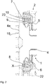
- Fig. 2 illustrates the positioning of the heat shield 7 between the pressure plate head 4a and the bellows 5 in a detailed view of the application device 1 of the disc brake 2 Fig. 1 .
- the heat shield 7 is free on the pressure plate 4 arranged and coated with an elastomer 9.
- the heat protection shield 7 rests against the pressure plate head 4a with a play without a pressing method.
- the distance X of approximately 1 mm between the pressure plate head 4a and the heat protection shield 7 can be clearly seen.
- the additional distance X between the pressure plate head 4a and the heat protection shield 7 lowers the temperature of the radiating heat which is generated during application of the brake pads 14, 15 the brake disc is created.
- the bellows 5 is protected against excessive temperatures by the insulating layer 8 of air.
- the elastomer 9 of the heat shield 7 is an additional protection and prevents the metal ring 10 of the heat shield 7 from sticking to the bellows 5.
- the elastomer 9 of the heat shield 7 also has openings 23. The openings 23 serve as tool supports in the casing of the metal ring 10.
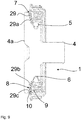
- FIG. 2a Another version of the heat shield 7 after 1 to 2 shows Fig. 2a .
- the heat shield 7 has an elastomer 9a only on a side S of the metal ring 10 facing the bellows 5. That is, the elastomer 9a of the heat shield 7 does not coat the metal ring 10 of the heat shield 7, but the metal ring 10 of the heat shield 7 is coated on the side S facing the bellows 5 with the elastomer 9a of the heat shield 7.
- Fig. 3 is the heat shield 7 after the 1 to 2 shown in detail.
- the design of the heat shield 7 as an O-ring is clearly visible.
- the openings 23 of the elastomer 9 are visible.
- the openings 23 are only one-sided in the embodiment Elastomer 9 introduced.
- Fig. 3a shows the heat shield 7 Fig. 1 , Fig. 2 and Fig. 3 in cross section.
- the full encasing of the metal ring 10 of the heat shield 7 with the elastomer 9 of the heat shield 7 can be seen.
- Fig. 3b shows a last detailed view of the heat shield 7 after Fig. 1 , Fig. 2 , Fig. 3 and Fig. 3a in cross section.
- Fig. 4 shows a second embodiment of the heat shield 7 on the pressure plate 4, the bellows 5 is not shown for a better plan view of the heat shield 7.
- the heat protection shield 7 has axially a pressure plate axis DA, in the direction of the pressure plate head 4a, pins 24, 24a, 24b.
- the pins 24, 24a, 24b engage in grooves 25, 25a, 25b of the pressure plate head 4a.
- the heat protection shield 7 is arranged parallel to the pressure plate head 4a with respect to the pressure plate head 4a.
- Fig. 5 shows an application device 1 1 to 2 with a heat shield 7 after Fig. 4 .
- the parallel arrangement of the heat protection shield 7 with respect to the pressure plate head 4a can be seen particularly well.
- the heat protection shield 7 is arranged between the bellows 5 and the pressure plate head 4a.
- the engagement of the pin 24 of the heat shield 7 in the groove 25 of the pressure plate head 4a is shown in detail.
- the heat protection shield 7 is in the execution Fig. 5 a metal ring 10 encased with the elastomer 9.
- Fig. 6 is the heat shield 7 after Fig. 4 and 5 shown in detail.
- the heat protection shield 7 has 6 pins 24, 24a, 24b, 24c, 24d, 24e, which are arranged axially of an axis HA of the heat protection shield 7 on the outer edge of the heat protection shield 7.
- the heat shield 7 has a coating with an elastomer 9a on the side on which the pins 24, 24a, 24b, 24c, 24d, 24e are arranged.
- Fig. 6a shows the heat shield 7 4 to 6 from the back.
- the rear side that is to say the opposite side on which the pins 24, 24a, 24b, 24c, 24d, 24e are arranged, has a coating with an elastomer 9a.
- Fig. 7 shows a third embodiment of the heat shield 7 after Fig. 1 and Fig. 2 .
- the heat shield 7 has knobs 28, 28a, 28b, 28c, 28d, 28e, 28f, 28g, 28h, 28i, 28j, 28k for supporting the heat shield 7 on the pressure plate head 4a.
- the knobs 28, 28a, 28b, 28c, 28d, 28e, 28f, 28g, 28h, 28i, 28j, 28k have a rectangular shape and are formed from the elastomer 9.
- the knobs 28, 28a, 28b, 28c, 28d, 28e, 28f, 28g, 28h, 28i, 28j, 28k are arranged in a circle on the elastomer 9.
- Two knobs 28, 28a, 28b, 28c, 28d, 28e, 28f, 28g, 28h, 28i, 28j, 28k. are arranged radially above the axis HA of the heat shield 7.
- Fig. 7a shows an application device 1 Fig. 1 and Fig. 2 with a heat shield Fig. 7 .
- the heat shield 7 is partially supported by the knobs 28, 28a, 28g, 28f on the pressure plate head 4a.
- An insulating layer 8 of air is arranged between the knobs 28, 28a, 28g, 28f of the heat protection shield 7 and the pressure plate head 4a.
- Fig. 8 shows a further embodiment of the arrangement of the heat shield 7 on the pressure plate head 4a of the application device 1 according to Fig. 1 and Fig. 2 .
- the heat protection shield 7 has a circumferential shoulder 31 radially at the outer end of the heat protection shield 7.
- the circumferential shoulder 31 of the heat shield 7 is created by a mechanical deformation of the heat shield 7.
- the heat shield 7 with the circumferential shoulder 31 corresponds to an L-shape.
- a circumferential groove 30 is embedded radially on the outer edge of the pressure plate head 4a by means of the pressing process.
- the heat shield 7 is supported with the circumferential shoulder 31 in the circumferential groove 30 of the pressure plate head 4a.
- the side of the heat shield 7 opposite the circumferential shoulder 31 of the heat shield 7 is supported on the bellows 5 (see FIG. Fig. 5 ).
- Fig. 8a shows again the circumferential groove 30 of the pressure plate head 4a of the pressure plate 4 Fig. 1 and Fig. 2 in detail.
- FIG. 9 is a further embodiment of the application device 1 with a heat shield 7 after Fig. 1 and Fig. 2 shown.
- Support elements 29, 29a, 29b, 29c are arranged on the pressure plate head 4a in the direction of the heat protection shield.
- the support elements 29, 29a, 29b, 29c have the same effect as the knobs 28, 28a, 28b, 28c, 28d, 28e, 28f, 28g, 28h, 28i, 28j, 28k according to the heat protection shield Fig. 7 and Fig. 7a .
- Air is contained between the support elements 29, 29a, 29b, 29c as an insulating layer 8 to prevent the heat shield 7 from sticking to the pressure plate head 4a.
- Fig. 9a shows again the pressure plate head 4a with the support elements 29, 29a, 29b, 29c according to Fig. 9 in detail.
Landscapes
- Engineering & Computer Science (AREA)
- General Engineering & Computer Science (AREA)
- Mechanical Engineering (AREA)
- Transportation (AREA)
- Braking Arrangements (AREA)
Abstract
Description
- Die Erfindung betrifft eine Zuspanneinrichtung für Scheibenbremsen von Nutzfahrzeugen und eine Scheibenbremse für Nutzfahrzeuge.
- Im Nutzfahrzeugbereich sind Scheibenbremsen und deren Aufbau hinlänglich bekannt. Bevorzugt werden in der heutigen Zeit Gleitsattelscheibenbremsen eingesetzt. Während eines Bremsvorgangs wird eine Bremsscheibe der Scheibenbremse über eine Zuspannvorrichtung zugespannt. Eine über einen Bremszylinder bereitgestellte Kraft wird über einen in der Scheibenbremse angeordneten Drehhebel an die Zuspanneinrichtung übertragen. Eine in der Zuspanneinrichtung, axial in Richtung der Bremsscheibe, angeordnete Stellspindel überträgt die Zuspannkraft über ein Druckstück auf einen zuspannseitigen Bremsbelag, wobei der zuspannseitige Bremsbelag und der felgenseitige Bremsbelag die Bremsscheibe zuspannen. Die Scheibenbremse ist unterteilt in eine Felgenseite und in eine Zuspannseite. Unter einer Zuspannseite ist die Seite der Scheibenbremse definiert, an der die Bremsscheibe über eine Zuspanneinrichtung zugespannt wird. Als Felgenseite ist die in Richtung der Felge eines Fahrzeugs gerichtete Seite der Scheibenbremse definiert. Um zu vermeiden das Schmutz oder andere Umwelteinflüsse über einen Bremsscheibenschacht und eine an dem Bremssattel vorhandenen Öffnung für die Stellspindel in den Innenraum der Scheibenbremse gelangt, ist zwischen einem Druckteller der Stellspindel und der Öffnung für die Stellspindel ein Faltenbalg angeordnet. Der Faltenbalg verbindet den Druckteller der Stellspindel mit dem Bremssattel. Während eines Bremsvorgangs bewegt sich der Faltenbalg mit der Stellspindel axial in Richtung der Bremsscheibe oder nach einem Bremsvorgang axial entgegengesetzt der Bremsscheibe. Während eines Bremsvorgangs sind die Bremsbeläge mit der Bremsscheibe in Kontakt und erzeugen durch Reibung Wärme im Bereich des Faltenbalgs. Durch die Betätigung des Bremszylinders und der beim Bremsvorgang erzeugten Wärme, entsteht ein Überdruck im Bremssattel und in einer Zuspannbox, infolgedessen sich der Faltenbalg aufbläht, sich an der entgegengesetzt der Bremsscheibe aufweisenden Rückseite des Drucktellers anlegt und durch die hohen Temperaturen kleben bleibt. Die Zuspannbox umfasst eine Zuspanneinrichtung, eine Nachstelleinrichtung und ein Druckstück. Nach Abkühlung kommt es in dem Faltenbalg häufig zu Rissbildungen.
- Die
DE102007059777B4 löst das Problem des Aufblähens und des Ankleben des Faltenbalgs an dem Druckteller, indem der Faltenbalg aus einem Hochtemperatur-Material hergestellt ist. Allerdings hat sich gezeigt, dass das Hochtemperaturmaterial eine geringe Rissfestigkeit und eine geringe Lebensdauer aufweist. Zudem ist Hochtemperaturmaterial in der Anschaffung sehr kostenintensiv. - Die
DE102008054162A1 offenbart beispielsweise ein als Isolierschild definiertes Hitzeschutzschild, das an dem Druckteller der Stellspindel vollständig oder zumindest weitgehend vollflächig anliegt. Nachteilig ist, dass die Wärme, ausgehend von der Bremsscheibe, direkt auf dem Hitzeschutzschild übertragen wird. Diese Hitzeschutzschilder bestehen auch aus einem Hochtemperatur-resistenten Material was zur Folge hat, dass der Hitzeschutzschild vorzeitig Risse bildet und der Hitzeschutzschild aus Sicherheitsgründen überdurchschnittlich oft ausgetauscht werden muss. - Aufgabe der Erfindung ist es, ein Hitzeschutzschild für eine Zuspanneinrichtung und eine Scheibenbremse für Nutzfahrzeuge bereit zu stellen, welche die Nachteile aus dem zuvor genannten Stand der Technik überwindet.
- Die Aufgabe wird dadurch gelöst, dass in einer Zuspanneinrichtung einer Scheibenbremse zwischen einem Drucktellerkopf, einer Stellspindel und einem Faltenbalg ein Hitzeschutzschild angeordnet ist, wobei der Hitzeschutzschild mit einem Abstand X zwischen dem Drucktellerkopf und dem Hitzeschutzschild angeordnet ist. Der Hitzeschutzschild ist nicht vollflächig an der Rückseite des Drucktellers angeordnet. Mit anderen Worten ist der Hitzeschutzschild nicht vollflächig an der der Bremsscheibe abgewandten Seite eines Drucktellers, angeordnet. Der Abstand zu dem Hitzeschutzschild verhindert ein Ankleben des Hitzeschutzschildes an dem Drucktellerkopf. Das heißt, dass mit dem Abstand der Wärmeübergang der Bremsscheibe zwischen dem Druckteller und dem Hitzeschutzschild unterbrochen wird. Ein weiterer Vorteil des Abstandes zwischen dem Hitzeschutzschild und dem Druckteller ist, dass auf Hochtemperatur-Material für das Hitzeschutzschild verzichtet werden kann.
- Es hat sich weiterhin als Vorteil erwiesen, dass die Zuspanneinrichtung zwischen dem Druckteller und dem Hitzeschutzschild eine isolierende Schicht aufweist. Die isolierende Schicht unterbricht den Wärmeübergang, ausgehend von der Bremsscheibe in Richtung des Faltenbalgs, weshalb sich die von der Bremsscheibe abgewandte Seite des Hitzeschutzschilds abkühlt und die Oberflächentemperatur an dem Hitzeschutzschild niedriger ist, als die Oberflächentemperatur an dem Hitzeschutzschild ohne einer Isolationsschicht.
- In einer weiteren Ausführung ist der Hitzeschutzschild ein mit einem Elastomer ummantelter Metallring oder ein mit einem Elastomer beschichteter Metallring. Die Basis des Hitzeschutzschildes bildet ein aus Metall geformter Ring. Es sind aber auch andere Materialien, wie Kunststoffe oder Verbundwerkstoffe denkbar. Der Metallring stabilisiert den Hitzeschutzschild und hält den Hitzeschutzschild an der Stellspindel in Position. Zusätzlich ummantelt ein Elastomer den Metallring. Denkbar sind auch Polymere, die den Metallring ummanteln. Das Elastomer absorbiert die abstrahlende Wärme von der Bremsscheibe und schützt den Faltenbalg vor einem Verkleben oder anders ausgedrückt, vor einem Verschweißen des Metallrings mit dem Druckteller durch die abstrahlende Wärme der Bremsscheibe. Es ist auch denkbar das Elastomer auf den Metallring aufzusprühen. Der Hitzeschutzschild hat die Aufgabe den Faltenbalg gegen ein Ankleben an dem Druckteller der Stellspindel zu schützen.
- Der Metallring ist in einer weiteren Ausgestaltung nur einseitig mit dem Elastomer beschichtet um Kosten zu reduzieren. Bei einer einseitigen Beschichtung des Metallrings ist die dem Faltenbalg zugewandte Seite des Metallrings zu beschichten, damit der Faltenbalg nicht an dem Metallring anklebt und nach einer Abkühlung des Metallrings Risse bildet.
- In einer weiteren Ausgestaltung ist der Metallring einseitig, mit der dem Faltenbalg abgewandten Seite des Metallrings, mit dem Elastomer beschichtet, damit die Temperatur des Hitzeschutzschildes niedriger gehalten wird.
- Darüber hinaus ist in einer weiteren Ausgestaltung der Hitzeschutzschild aus Kunststoff oder Silikon gebildet. Sowohl der Ring zur Formgebung und Stabilität des Hitzeschutzschildes, als auch die Ummantelung oder die Beschichtung sind vollständig aus Kunststoff oder aus Silikon. Es ist denkbar, den Hitzeschutzschild aus einem einzigen Kunststoff oder aus mehreren Kunststoffen herzustellen.
- Weiterhin hat sich gezeigt, dass der Hitzeschutzschild vorteilhaft an dem Druckteller oder dem Drucktellerkopf mit einer Anordnung, umfassend Presssitz oder frei Position, angeordnet ist. Als Presssitz ist die Verbindung des Hitzeschutzschildes mit dem Druckteller definiert, bei der nach der Anordnung des Hitzeschutzschildes an dem Druckteller eine Presspassung entsteht und Längs-sowie Querkräfte kraftschlüssig übertragen werden. Der Hitzeschutzschild kann sich nicht mehr axial entlang der Stellspindel bewegen. In der zweiten denkbaren Anordnung "frei Position" kann sich der Hitzeschild axial entlang des Drucktellers nahezu frei bewegen bzw. der Hitzeschild hat vorzugsweise ein axiales Spiel von 0,1 mm bis 3 mm, weiter bevorzugt von 0,1 mm bis 1 mm. Der Hitzeschild ist lediglich durch den Abschlussbund des Faltenbalgs eingeschränkt.
- Es hat sich in einer weiteren Ausführung als Vorteil erwiesen, dass die isolierende Schicht eine Luftschicht ist. Luft weist gegenüber anderen Stoffen, Stoffgemischen oder Festkörper einen sehr niedrigen Wärmeleitkoeffizient von 0,024 [W / (m * K)] auf. Durch den niedrigen Wärmeleitkoeffizient der Luft wird die hohe Temperatur in der Scheibenbremse, gebildet durch die abgestrahlte Wärme der Bremsscheibe, bereits vor Erreichen des Hitzeschutzschildes deutlich gesenkt.
- Der Hitzeschutzschild ist in einer weiteren Ausführung als O-Ring ausgebildet. Sowohl der Druckteller, als auch der Faltenbalg weisen eine kreisförmige Geometrie auf, sodass der Hitzeschutzschild den Faltenbalg vollflächig oder zumindest teilweise gegen ein Ankleben an dem Drucktellerkopf überdeckt. Weiterhin kann der als O-Ring ausgebildete Hitzeschutzschild am Drucktellerkopf zentriert, bzw. positioniert werden. Insbesondere ist der Abstand zwischen dem Drucktellerkopf und dem Hitzeschutzschild in einer weiteren Ausführung größer gleich 1 mm. Der Abstand ist zur Anordnung oder zum Befüllen einer zusätzlichen Isolationsschicht erforderlich. Zudem verringert sich die Temperatur mit zunehmendem Abstand von der Bremsscheibe. Darüber hinaus kann in der Montage ab einem Abstand größer gleich 1 mm zwischen dem Drucktellerkopf und dem Hitzeschutzschild der Toleranzbereich eingehalten werden.
- Es hat sich weiterhin gezeigt, dass der Hitzeschild, bezogen auf den Drucktellerkopf, in einer weiteren Ausgestaltung parallel oder schräg zwischen dem Drucktellerkopf und dem Faltenbalg angeordnet ist. Je nach Ausgestaltung des Drucktellers kann der Hitzeschutzschild schräg oder parallel zu dem Drucktellerkopf angeordnet werden, wodurch ein gleichmäßiger Abstand, daher eine gleichmäßige Isolierschicht, zwischen dem Hitzeschutzschild und dem Drucktellerkopf erzielt wird. Die gleichmäßige Isolierschicht weist den Vorteil auf, dass der Wärmeübergang an der gesamten Fläche oder zumindest überwiegend an der gesamten Fläche des Hitzeschutzschildes gleich hoch ist.
- Zudem weist in einer weiteren Ausbildung der Hitzeschutzschild in Richtung des Drucktellerkopfes Zapfen oder Nuten auf.
- Die Zapfen des Hitzeschutzschildes sind nach einer weiteren Ausgestaltung dazu ausgebildet in Nuten des Drucktellerkopfes zu greifen. Weiterhin können die Zapfen des Drucktellerkopfes in die Nuten des Hitzeschutzschildes greifen. Mit den Zapfen ist der Hitzeschutzschild zudem verdrehsicher mit dem Druckteller, insbesondere mit dem Drucktellerkopf, verbunden. Außerdem ist mit der Zapfenanordnung an dem Hitzeschutzschild ein gleichmäßiger Schutz des Faltenbalgs vor Hitzeeinwirkungen, ausgehend von der Bremsscheibe und den Bremsbelägen, vorhanden.
- Es hat in einer weiteren Ausgestaltung vorgesehen, dass der Hitzeschutzschild mindestens 3 Zapfen und der Drucktellerkopf mindestens 3 Nuten aufweist. Die Zapfen des Hitzeschutzschildes und die Nuten des Drucktellerkopfes sind vorteilhaft geometrisch als Dreiecksform angeordnet und sichern den Hitzeschutzschild vor einer axialen Drehbewegung. Der Freiraum zwischen den Zapfen des Hitzeschutzschildes ermöglicht Luftbewegungen und / oder Konvektion, wodurch ein Wärmestau zwischen dem Drucktellerkopf und dem Hitzeschutzschild vermieden wird. Die axiale Drehbewegung des Hitzeschutzschildes muss nicht vollständig unterbunden werden. Das heißt, dass der Hitzeschutzschild ein axiales Spiel aufweisen kann, wobei die Nuten des Drucktellerkopfes in ihrer Abmessung größer sind als die Zapfen des Hitzeschutzschildes. Zudem sind die Nuten des Drucktellerkopfes und die Zapfen des Hitzeschutzschildes als Presssitz zur Positionierung des Hitzeschutzschildes an dem Drucktellerkopf ausgelegt.
- Besonders vorteilhaft weist der Hitzeschutzschild in einer zweiten Ausführungsform 6 Zapfen und der Drucktellerkopf 6 Nuten auf. Mit der zweiten Ausführungsform ist ein besonders sicheres Abstützen des Hitzeschutzschildes an dem Drucktellerkopf möglich.
- Zudem ist in einer weiteren Ausführungsform vorgesehen, dass ein umlaufender Zapfen an dem Hitzeschutzschild angeordnet ist und in eine umlaufende Nut des Drucktellerkopfes greift. Vorteile des umlaufenden Absatzes des Hitzeschutzschildes ergeben sich in der Montage, da der umlaufende Absatz des Drucktellerkopfes ohne weiteres verdrehen des Drucktellerkopfes in die umlaufende Nut des Drucktellerkopfes montiert werden kann.
- Die Zapfen des Hitzeschutzschildes sind in einer weiteren Ausführung, bezogen auf eine Drucktellerachse, radial außen an dem Hitzeschutzschild angeordnet. Mit der Anordnung der Zapfen an dem äußeren Bereich des Hitzeschutzschildes lässt sich der Hitzeschutzschild einfach durch maschinelle Prozesse wie Stanz- und Umformprozesse oder durch Drehprozesse bearbeiten. Ein zusätzliches Anbringen der Zapfen an dem Hitzeschutzschild ist nicht erforderlich.
- Darüber hinaus weist in einer weiteren Ausgestaltung der Hitzeschild in Richtung des Drucktellerkopfes Noppen auf. Die Noppen des Drucktellerkopfes dienen der Abstützung des Hitzeschutzschildes an dem Drucktellerkopf. Es ist auch denkbar, dass zur Abstützung des Hitzeschutzschildes an dem Drucktellerkopf, der Drucktellerkopf in Richtung des Hitzeschutzschildes Noppen aufweist. Die Noppen können in ihrer Geometrie unterschiedlich ausgestaltet sein und beispielsweise die Form eines Rechtecks, Quadrats, Dreiecks, Kreises aufweisen. Besonders vorteilhaft weist der Drucktellerkopf oder der Hitzeschutzschild eine gerade Anzahl an Noppen auf, damit der Drucktellerkopf gleichmäßig an dem Hitzeschutzschild oder der Hitzeschutzschild gleichmäßig an dem Drucktellerkopf anliegt.
- In einer weiteren Ausführung sind die Noppen Bestandteile des Elastomers des Hitzeschutzschildes. Mit anderen Worten ausgedrückt, die Noppen sind aus dem Elastomer geformt. Die Noppen können aber auch an dem Elastomer angeformt sein.
- Es hat sich weiterhin gezeigt, dass der Drucktellerkopf in einer weiteren Ausführung Abstützelemente in Richtung der Zuspannseite der Scheibenbremse aufweist. Die Abstützelemente sind geometrische Erhebungen, an denen sich der Hitzeschutzschild abstützt, wobei eine vollflächige Abstützung des Hitzeschutzschildes an dem Drucktellerkopf vermieden wird. Die Abstützelemente können in der Form variieren. Zusätzliche Kosten entstehen nicht, da die Abstützelemente gleichzeitig mit dem Druckteller oder dem Drucktellerkopf, während des Herstellungsprozesses, umfassend Stanzen oder Gießen, des Drucktellers oder nur des Drucktellerkopfes ausgebildet werden.
- Darüber hinaus wird die Aufgabe in einer letzten vorteilhaften Ausführung durch eine Scheibenbremse für Kraftfahrzeuge gelöst, wobei die Scheibenbremse eine Zuspanneinrichtung nach einem der vorangegangenen Ausführungen aufweist.
- Nachfolgend werden ausgewählte Ausführungsbeispiele der Erfindung anhand der beigefügten Figuren erläutert.
- Es zeigt:
-
Fig. 1 eine Scheibenbremse in einer seitlich geschnittenen Ansicht mit einer erfindungsgemäßen Zuspanneinrichtung, -
Fig. 2 einen Teilausschnitt der Zuspanneinrichtung mit einem Hitzeschutzschild, -
Fig.2a eine Detailansicht des Hitzeschutzschildes im eingebauten Zustand mit einem einseitig beschichteten Hitzeschild, -
Fig. 3 ein Hitzeschutzschild in einer seitlich gedrehten Ansicht, -
Fig. 3a eine geschnittene Ansicht des Hitzeschutzschildes im Querschnitt, -
Fig.3b eine Detailansicht des geschnittenen Hitzeschutzschildes nachFig. 3a , -
Fig. 4 eine seitlich gedrehte Ansicht des Druckstücks und einem Hitzeschutzschild mit Zapfen, -
Fig. 5 eine geschnittene Teilansicht einer Zuspanneinrichtung mit einem Hitzeschutzschild mit Zapfen, -
Fig. 6 ein Zapfen aufweisendes Hitzeschutzschild in einer seitlich gedrehten Frontalansicht, -
Fig. 6a ein Zapfen aufweisendes Hitzeschutzschild in einer seitlich gedrehten Rückansicht. -
Fig. 7 ein Hitzeschutzschild mit Noppen, -
Fig. 7a einen Druckteller mit einem Hitzeschutzschild nachFig. 7 im eingebauten Zustand, -
Fig. 8 einen Druckteller mit einer umlaufenden Nut im Drucktellerkopf und ein Hitzeschutzschild mit einem umlaufenden Absatz, -
Fig. 8a einen Druckteller mit einem Drucktellerkopf nachFig. 8 im Detail, -
Fig. 9 einen Druckteller mit Abstützelementen am Drucktellerkopf, -
Fig. 9a einen Druckteller mit Abstützelementen nachFig. 9 im Detail. -
Fig.1 zeigt eine seitlich geschnittene Ansicht einer Scheibenbremse 2 mit einer Zuspanneinrichtung 1. Die Scheibenbremse 2 weist eine Zuspannseite ZS und eine Felgenseite FS auf. Ein Bremsträger 11 weist an der Felgenseite FS einen Belagträgerschacht 12 zur Aufnahme eines Bremsbelags 14 und an der Zuspannseite ZS einen Belagträgerschacht 13 zur Aufnahme eines Bremsbelags 15 auf. Niederhaltefedern 17, 18 und ein Belaghaltebügel 19 sichern die Bremsbeläge 14, 15 gegen ein radiales Herausfallen aus den Bremsbelagträgerschächten 12, 13. Die Zuspanneinrichtung 1 weist einen Drehhebel 20 auf, der während eines Zuspannvorgangs eine mit einem Druckteller 4 aufweisende Stellspindel 3 axial, entlang einer axialen Achse A, in Richtung der Bremsbeläge 14, 15 verschiebt, wodurch die Bremsbeläge 14, 15 gegen eine nicht gezeigte Bremsscheibe gedrückt werden. Der Druckteller 4 weist eine umlaufende Nut 6 auf, in der ein Faltenbalg 5 angeordnet ist. Der Faltenbalg 5 ist durch einen Deckel zusätzlich mit einem Bremssattel 16 verbunden und schützt die Zuspanneinrichtung 1 gegen Umwelteinflüsse wie Staub, Sand, Steine oder Schnee. Zwischen dem Faltenbalg 5 und einem Drucktellerkopf 4a des Drucktellers 4 ist ein Hitzeschutzschild 7 angeordnet. Der Hitzeschutzschild 7 schützt den Faltenbalg 5 während des Rückstellvorgangs vor einem Ankleben an dem Drucktellerkopf 4a und während eines Zustellvorgangs gegen ein Abreißen von dem Drucktellerkopf 4a, also einer Beschädigung des Faltenbalgs 5. Der Hitzeschutzschild 7 besteht aus einem Metallring 10 und einem Elastomer 9. InFig. 1 ist der Hitzeschutzschild 7 mittels eines Pressverfahrens fest an dem Druckteller 4 angeordnet. Als zusätzliche Isolierung weist die Zuspanneinrichtung 1 zwischen dem Drucktellerkopf 4a und dem Hitzeschutzschild 7 eine aus Luft bestehende isolierende Schicht 8 (s.Fig. 2 und2a ) auf. Das heißt, der Hitzeschutzschild 7 ist nicht direkt an dem Drucktellerkopf 4a, sondern mit einem Abstand X von etwa 1 mm an dem Drucktellerkopf 4a angeordnet. Abschließend weist die Scheibenbremse 2 in dem Bremssattel 16 eine Nachstelleinrichtung 21 und ein Druckstück 22 zur Einstellung des Lüftspiels zwischen der Bremsscheibe und den Bremsbelägen 14, 15 auf. Als Lüftspiel ist der Abstand zwischen einem Bremsbelag 14, 15 und der Bremsscheibe definiert. -
Fig. 2 verdeutlicht die Positionierung des Hitzeschutzschildes 7 zwischen dem Drucktellerkopf 4a und dem Faltenbalg 5 in einer Detailansicht der Zuspanneinrichtung 1 der Scheibenbremse 2 nachFig. 1 . EntgegenFig. 1 ist der Hitzeschutzschild 7 frei an dem Druckteller 4 angeordnet und mit einem Elastomer 9 beschichtet. Mit anderen Worten ausgedrückt, der Hitzeschutzschild 7 liegt ohne ein Pressverfahren mit einem Spiel an dem Drucktellerkopf 4a an. Deutlich erkennbar ist der Abstand X von etwa 1 mm zwischen dem Drucktellerkopf 4a und dem Hitzeschutzschild 7. Der zusätzliche Abstand X zwischen dem Drucktellerkopf 4a und dem Hitzeschutzschild 7 senkt die Temperatur der abstrahlenden Wärme, welche bei einem Bremsvorgang durch Anlegen der Bremsbeläge 14, 15 an die Bremsscheibe entsteht. Der Faltenbalg 5 ist, zusätzlich zu dem Hitzeschild 7, durch die isolierende Schicht 8 aus Luft gegen zu hohen Temperaturen geschützt. Zu hohe Temperaturen führen zum Beispiel zu einem Ankleben des Faltenbalgs 5 an dem Druckteller 4, Drucktellerkopf 4a oder an dem Hitzeschutzschild 7. Das Elastomer 9 des Hitzeschutzschildes 7 ist ein zusätzlicher Schutz und vermeidet ein Ankleben des Metallrings 10 des Hitzeschutzschildes 7 an dem Faltenbalg 5. Das Elastomer 9 des Hitzeschutzschildes 7 weist darüber hinaus Öffnungen 23 auf. Die Öffnungen 23 dienen als Werkzeugauflagen bei der Ummantelung des Metallrings 10. - Eine weitere Ausführung des Hitzeschutzschildes 7 nach
Fig. 1 bis 2 zeigtFig. 2a . Der Hitzeschutzschild 7 weist allerdings nur an einer dem Faltenbalg 5 zugewandten Seite S des Metallrings 10 ein Elastomer 9a auf. Das heißt, das Elastomer 9a des Hitzeschutzschildes 7 ummantelt nicht den Metallring10 des Hitzeschutzschildes 7, sondern der Metallring 10 des Hitzeschutzschildes 7 ist an der dem Faltenbalg 5 zugewandten Seite S mit dem Elastomer 9a des Hitzeschutzschildes 7 beschichtet. - In
Fig. 3 ist der Hitzeschutzschild 7 nach denFig. 1 bis 2 im Detail gezeigt. Gut erkennbar ist die Ausgestaltung des Hitzeschutzschildes 7 als O-Ring. Zudem sind die Öffnungen 23 des Elastomers 9 sichtbar. Die Öffnungen 23 sind in dem Ausführungsbeispiel nur einseitig in das Elastomer 9 eingebracht. Wenn das Hitzeschutzschild 7 in die Scheibenbremse 2 nachFig. 1 bis 2a verbaut ist, zeigen die Öffnungen 23 in Richtung der Felgenseite FS. -
Fig. 3a zeigt den Hitzeschutzschild 7 nachFig. 1 ,Fig. 2 undFig. 3 im Querschnitt. Insbesondere ist im Detail die Vollummantelung des Metallrings 10 des Hitzeschutzschildes 7 mit dem Elastomer 9 des Hitzeschutzschildes 7 erkennbar. -
Fig. 3b zeigt eine letzte Detailansicht des Hitzeschutzschildes 7 nachFig. 1 ,Fig. 2 ,Fig. 3 undFig. 3a im Querschnitt. -
Fig. 4 zeigt eine zweite Ausführungsform des Hitzeschutzschildes 7 an dem Druckteller 4, wobei der Faltenbalg 5 für eine bessere Draufsicht auf dem Hitzeschutzschild 7 nicht gezeigt ist. Der Hitzeschutzschild 7 weist axial einer Drucktellerachse DA, in Richtung des Drucktellerkopfes 4a, Zapfen 24, 24a, 24b auf. Die Zapfen 24, 24a, 24b greifen in Nuten 25, 25a, 25b des Drucktellerkopfes 4a. Zwischen dem Hitzeschutzschild 7 und dem Drucktellerkopf 4a befindet sich Luft als isolierende Schicht 8. Der Hitzeschutzschild 7 ist, bezogen auf den Drucktellerkopf 4a, parallel zu dem Drucktellerkopf 4a angeordnet. -
Fig. 5 zeigt eine Zuspanneinrichtung 1 nachFig. 1 bis 2 mit einem Hitzeschutzschild 7 nachFig. 4 . Besonders gut zu erkennen ist die, bezogen auf den Drucktellerkopf 4a, parallele Anordnung des Hitzeschutzschildes 7. Der Hitzeschutzschild 7 ist zwischen dem Faltenbalg 5 und dem Drucktellerkopf 4a angeordnet. Insbesondere ist im Detail der Eingriff des Zapfens 24 des Hitzeschutzschildes 7 in die Nut 25 des Drucktellerkopfes 4a gezeigt. Der Hitzeschutzschild 7 ist in der Ausführung nachFig. 5 ein mit dem Elastomer 9 ummantelter Metallring 10. - In
Fig. 6 ist der Hitzeschutzschild 7 nachFig. 4 und5 im Detail gezeigt. Der Hitzeschutzschild 7 weist 6 Zapfen 24, 24a, 24b, 24c, 24d, 24e auf, die axial einer Achse HA des Hitzeschutzschildes 7 an dem äußeren Rand des Hitzeschutzschildes 7 angeordnet sind. Zudem weist das Hitzeschutzschild 7 an der Seite, an der die Zapfen 24, 24a, 24b, 24c, 24d, 24e angeordnet sind, eine Beschichtung mit einem Elastomer 9a auf. -
Fig. 6a zeigt den Hitzeschutzschild 7 nachFig. 4 bis 6 von der Rückseite. In dem Ausführungsbeispiel weist die Rückseite, also der gegenüberliegenden Seite an der die Zapfen 24, 24a, 24b, 24c, 24d, 24e angeordnet sind, eine Beschichtung mit einem Elastomer 9a auf. -
Fig. 7 zeigt eine dritte Ausführungsform des Hitzeschutzschildes 7 nachFig.1 undFig. 2 . In der dritten Ausführungsform weist der Hitzeschutzschild 7 Noppen 28, 28a, 28b, 28c, 28d, 28e, 28f, 28g, 28h, 28i, 28j, 28k zum Abstützen des Hitzeschutzschildes 7 an dem Drucktellerkopf 4a auf. Die Noppen 28, 28a, 28b, 28c, 28d, 28e, 28f, 28g, 28h, 28i, 28j, 28k weisen eine Rechteckform auf und sind aus dem Elastomer 9 geformt. Zudem sind die Noppen 28, 28a, 28b, 28c, 28d, 28e, 28f, 28g, 28h, 28i, 28j, 28k kreisförmig auf dem Elastomer 9 angeordnet. Je zwei Noppen 28, 28a, 28b, 28c, 28d, 28e, 28f, 28g, 28h, 28i, 28j, 28k. sind radial der Achse HA des Hitzeschutzschildes 7 übereinander angeordnet. -
Fig. 7a zeigt eine Zuspanneinrichtung 1 nachFig. 1 undFig. 2 mit einem Hitzeschutzschild nachFig. 7 . Das Hitzeschutzschild 7 stützt sich teilweise mit den Noppen 28, 28a, 28g, 28f an dem Drucktellerkopf 4a ab. Zwischen den Noppen 28, 28a, 28g, 28f des Hitzeschutzschildes 7 und dem Drucktellerkopf 4a ist eine isolierende Schicht 8 aus Luft angeordnet. -
Fig. 8 zeigt ein weiteres Ausführungsbeispiel zur Anordnung des Hitzeschutzschildes 7 am Drucktellerkopf 4a der Zuspanneinrichtung 1 gemäßFig. 1 undFig. 2 . Der Hitzeschutzschild 7 weist radial am äußeren Ende des Hitzeschutzschildes 7 einen umlaufenden Absatz 31 auf. Der umlaufende Absatz 31 des Hitzeschutzschildes 7 entsteht durch eine maschinelle Verformung des Hitzeschutzschildes 7. Im Querschnitt entspricht der Hitzeschutzschild 7 mit dem umlaufenden Absatz 31 einer L-Form. Radial am äußeren Rand des Drucktellerkopfes 4a ist eine umlaufende Nut 30 mittels Pressverfahren eingelassen. Der Hitzeschutzschild 7 stützt sich mit dem umlaufenden Absatz 31 in der umlaufenden Nut 30 des Drucktellerkopfes 4a ab. Die dem umlaufenden Absatz 31 des Hitzeschutzschildes 7 gegenüberliegende Seite des Hitzeschutzschildes 7 stützt sich an dem Faltenbalg 5 (s.Fig. 5 ) ab. -
Fig. 8a zeigt noch einmal die umlaufende Nut 30 des Drucktellerkopfes 4a des Drucktellers 4 nachFig. 1 undFig. 2 im Detail. - In
Fig. 9 ist eine weitere Ausgestaltung der Zuspanneinrichtung 1 mit einem Hitzeschutzschild 7 nachFig. 1 undFig. 2 gezeigt. An dem Drucktellerkopf 4a sind in Richtung des Hitzeschutzschildes 7 Abstützelemente 29, 29a, 29b, 29c angeordnet. Die Abstützelemente 29, 29a, 29b, 29c weisen die gleiche Wirkung auf, wie die Noppen 28, 28a, 28b, 28c, 28d, 28e, 28f, 28g, 28h, 28i, 28j, 28k des Hitzeschutzschildes gemäßFig. 7 undFig. 7a . Zwischen den Abstützelementen 29, 29a, 29b, 29c ist Luft als isolierende Schicht 8 gegen ein Ankleben des Hitzeschutzschildes 7 an dem Drucktellerkopf 4a enthalten. -
Fig. 9a zeigt noch einmal den Drucktellerkopf 4a mit den Abstützelementen 29, 29a, 29b, 29c gemäßFig. 9 im Detail. -
- 1
- Zuspanneinrichtung
- 2
- Scheibenbremse
- 3
- Stellspindel
- 4
- Druckteller
- 4a
- Drucktellerkopf
- 5
- Faltenbalg
- 6
- umlaufende Nut des Drucktellers 4
- 7
- Hitzeschutzschild
- 8
- isolierende Schicht
- 9, 9a
- Elastomer des Hitzeschutzschildes 7
- 10
- Metallring des Hitzeschutzschildes 7
- 11
- Bremsträger
- 12-13
- Belagträgerschacht
- 14-15
- Bremsbelag
- 16
- Bremssattel
- 17, 18
- Niederhaltefeder
- 19
- Belaghaltebügel
- 20
- Drehhebel
- 21
- Nachstelleinrichtung
- 22
- Druckstück
- 23
- Öffnungen des Elastomers 9 des Hitzeschutzschildes 7
- 24-24e
- Zapfen des Hitzeschutzschildes 7
- 25-25b
- Nuten des Drucktellerkopfes 4a
- 28-28k
- Noppen des Hitzeschutzschildes (7)
- 29-29c
- Abstützelemente des Drucktellerkopfes (4a)
- 30
- umlaufende Nut des Drucktellerkopfes (4a)
- 31
- umlaufender Absatz des Hitzeschutzschildes (7)
- A
- Axiale Achse der Zuspanneinrichtung 1
- DA
- Drucktellerachse
- HA
- Achse des Hitzeschutzschildes 7
- S
- dem Faltenbalg zugewandte Seite des Metallrings 10
- X
- Abstand zwischen Druckteller 4 und Hitzeschutzschild 7
- FS
- Felgenseite
- ZS
- Zuspannseite
Claims (20)
- Zuspanneinrichtung (1) für eine Scheibenbremse (2) von Nutzfahrzeugen umfassend eine Stellspindel (3) mit einem axial an der Stellspindel (3) angeordneten Druckteller (4) mit einem Drucktellerkopf 4a und wobei der Druckteller (4) zur Aufnahme eines Faltenbalgs (5) radial eine umlaufende Nut (6) aufweist, dadurch gekennzeichnet, dass zwischen dem Drucktellerkopf (4a) und dem Faltenbalg (5) ein Hitzeschutzschild (7) zumindest teilweise mit einem Abstand (X) angeordnet ist.
- Zuspanneinrichtung (1) nach Anspruch 1, dadurch gekennzeichnet, dass die Zuspanneinrichtung (1) zwischen dem Drucktellerkopf (4a) und dem Hitzeschutzschild (7) eine isolierende Schicht (8) aufweist.
- Zuspanneinrichtung (1) nach Anspruch 1 oder 2, dadurch gekennzeichnet, dass der Hitzeschutzschild (7) ein mit einem Elastomer (9) ummantelter Metallring (10) oder ein mit einem Elastomer (9a) beschichteter Metallring (10) ist.
- Zuspanneinrichtung (1) nach Anspruch 3, dadurch gekennzeichnet, dass der Metallring (10) einseitig, mit der dem Faltenbalg (6) zugewandten Seite (S), mit einem Elastomer (9a) beschichtet ist.
- Zuspanneinrichtung (1) nach Anspruch 3, dadurch gekennzeichnet, dass der Metallring (10) einseitig, mit der dem Faltenbalg (6) abgewandten Seite (S), mit einem Elastomer (9a) beschichtet ist.
- Zuspanneinrichtung (1) nach Anspruch 1 oder 2, dadurch gekennzeichnet, dass der Hitzeschutzschild (7) ein Kunststoffteil oder oder ein Silikonteil ist.
- Zuspanneinrichtung (1) nach einem der vorangegangenen Ansprüche, dadurch gekennzeichnet, dass der Hitzeschutzschild (7) an dem Druckteller (4) oder dem Drucktellerkopf (4a) mit einer Anordnung, umfassend Presssitz oder frei Position, angeordnet ist.
- Zuspanneinrichtung (1) nach Anspruch 2, dadurch gekennzeichnet, dass die isolierende Schicht (8) eine Luftschicht ist.
- Zuspanneinrichtung (1) nach einem der vorangegangenen Ansprüche, dadurch gekennzeichnet, dass der Hitzeschutzschild (7) die Form eines O-Rings aufweist.
- Zuspanneinrichtung (1) nach einem der vorangegangenen Ansprüche, dadurch gekennzeichnet, dass der Hitzeschutzschild (7) zumindest teilweise mit einem Abstand (X) größer gleich 1 mm zwischen dem Drucktellerkopf (4a) und dem Hitzeschutzschild (7) angeordnet ist.
- Zuspanneinrichtung (1) für eine Scheibenbremse (2) nach einem der vorangegangenen Ansprüche, dadurch gekennzeichnet, dass der Hitzeschutzschild (7), bezogen auf dem Drucktellerkopf (4a), parallel oder schräg zwischen dem Drucktellerkopf (4a) und dem Faltenbalg (5) angeordnet ist.
- Zuspanneinrichtung (1) nach einem der vorangegangenen Ansprüche, dadurch gekennzeichnet, dass der Hitzeschutzschild (7) in Richtung des Drucktellerkopfes (4a) Zapfen (24, 24a, 24b, 24c, 24d, 24e) aufweist.
- Zuspanneinrichtung (1) für eine Scheibenbremse (2) nach Anspruch 12, dadurch gekennzeichnet, dass der Drucktellerkopf (4a) Nuten (25, 25a, 25b) aufweist und die Nuten (25, 25a, 25b) dazu ausgebildet sind die Zapfen (24, 24a, 24b, 24c, 24d, 24e) des Hitzeschutzschildes (7) aufzunehmen.
- Zuspanneinrichtung (1) für eine Scheibenbremse (2) nach Anspruch 13, dadurch gekennzeichnet, dass der Hitzeschutzschild (7) mindestens 3 Zapfen (24, 24a, 24b, 24c, 24d, 24e) und der Drucktellerkopf (4a) mindestens 3 Nuten (25, 25a, 25b) aufweist.
- Zuspanneinrichtung (1) für eine Scheibenbremse (2) nach einem der vorangegangenen Ansprüche, dadurch gekennzeichnet, dass der Hitzeschutzschild (7) einen umlaufenden Absatz (31) aufweist und der Drucktellerkopf 4a eine umlaufende Nut (30) zur Aufnahme des umlaufenden Absatzes (31) aufweist.
- Zuspanneinrichtung (1) für eine Scheibenbremse (2) nach einem der Ansprüche 12 bis 14, dadurch gekennzeichnet, dass die Zapfen (24, 24a, 24b, 24c, 24d, 24e) des Hitzeschutzschildes (7), bezogen auf eine Drucktellerachse (DA), radial außen an dem Hitzeschutzschild (7) angeordnet sind.
- Zuspanneinrichtung (1) nach einem der vorangegangenen Ansprüche, dadurch gekennzeichnet, dass der Hitzeschutzschild (7), in Richtung des Drucktellerkopfes (4a), Noppen (28, 28a, 28b, 28c, 28d, 28e, 28f, 28g, 28h, 28i, 28j, 28k) zur Abstützung des Hitzechutzschildes (7) an dem Drucktellerkopf (4a) aufweist.
- Zuspanneinrichtung (1) für eine Scheibenbremse (2) nach Anspruch 16, dadurch gekennzeichnet, dass die Noppen (28, 28a, 28b, 28c, 28d, 28e, 28f, 28g, 28h, 28i, 28j, 28k) des Hitzeschutzschildes Bestandteile des Elastomers (9) sind.
- Zuspanneinrichtung (1) nach einem der vorangegangenen Ansprüche, dadurch gekennzeichnet, dass der Drucktellerkopf (4a), in Richtung der Zuspannseite (ZS), Abstützelemente (29, 29a, 29b, 29c) zum Abstützen des Hitzeschutzschilds (7) aufweist.
- Scheibenbremse (2) für Kraftfahrzeuge umfassend einen Bremsträger (11) mit zumindest einem, in einem Belagträgerschacht (12, 13) angeordneten Bremsbelag (14, 15), einen dem Bremsträger (11) umgreifenden Bremssattel (16) zum axialen Zuspannen zumindest eines Bremsbelags (13, 14) an eine Bremsscheibe, wobei eine an einer Zuspannseite (ZS) des Bremsensattels (16) angeordnete Zuspanneinrichtung (1) eine Bremsscheibe über den Bremsbelag (15) während eines Bremsvorgangs zuspannt, dadurch gekennzeichnet, dass die Zuspanneinrichtung (1) nach einem der Ansprüche 1 bis 19 ausgebildet ist.
Priority Applications (3)
| Application Number | Priority Date | Filing Date | Title |
|---|---|---|---|
| EP19152037.8A EP3683467B1 (de) | 2019-01-16 | 2019-01-16 | Zuspanneinrichtung für eine scheibenbremse von nutzfahrzeugen und eine scheibenbremse für nutzfahrzeuge |
| US16/740,991 US11441627B2 (en) | 2019-01-16 | 2020-01-13 | Disc brake and brake application device for commercial vehicles |
| CN202010046410.5A CN111442043B (zh) | 2019-01-16 | 2020-01-16 | 用于商用车辆的盘式制动器的夹紧装置及盘式制动器 |
Applications Claiming Priority (1)
| Application Number | Priority Date | Filing Date | Title |
|---|---|---|---|
| EP19152037.8A EP3683467B1 (de) | 2019-01-16 | 2019-01-16 | Zuspanneinrichtung für eine scheibenbremse von nutzfahrzeugen und eine scheibenbremse für nutzfahrzeuge |
Publications (2)
| Publication Number | Publication Date |
|---|---|
| EP3683467A1 true EP3683467A1 (de) | 2020-07-22 |
| EP3683467B1 EP3683467B1 (de) | 2021-07-14 |
Family
ID=65033477
Family Applications (1)
| Application Number | Title | Priority Date | Filing Date |
|---|---|---|---|
| EP19152037.8A Active EP3683467B1 (de) | 2019-01-16 | 2019-01-16 | Zuspanneinrichtung für eine scheibenbremse von nutzfahrzeugen und eine scheibenbremse für nutzfahrzeuge |
Country Status (3)
| Country | Link |
|---|---|
| US (1) | US11441627B2 (de) |
| EP (1) | EP3683467B1 (de) |
| CN (1) | CN111442043B (de) |
Families Citing this family (3)
| Publication number | Priority date | Publication date | Assignee | Title |
|---|---|---|---|---|
| DE102018122726A1 (de) * | 2018-09-17 | 2020-03-19 | Bpw Bergische Achsen Kg | Blechanordnung für eine Scheibenbremse sowie Scheibenbremse mit einer Blechanordnung für ein Fahrzeug |
| US12535136B2 (en) * | 2023-07-17 | 2026-01-27 | Hl Mando Corporation | Brake assembly with boot assembly |
| DE102024116336A1 (de) * | 2024-06-11 | 2025-12-11 | Bpw Bergische Achsen Kommanditgesellschaft | Abstandshalter für eine Scheibenbremse eines Nutzfahrzeugs, Dichtungsbaugruppe und Scheibenbremse |
Citations (6)
| Publication number | Priority date | Publication date | Assignee | Title |
|---|---|---|---|---|
| DE9410455U1 (de) * | 1994-06-28 | 1995-10-26 | Lucas Industries P.L.C., Solihull, West Midlands | Abdichtung eines Stellkörpers gegen einen Führungskörper an einer Bremse |
| US5538109A (en) * | 1990-12-04 | 1996-07-23 | The B. F. Goodrich Company | Piston head for an aircraft brake and insulator |
| US20010047913A1 (en) * | 2000-05-24 | 2001-12-06 | Roberto Conti | Disk brake actuator |
| DE102008054162A1 (de) | 2008-10-31 | 2010-05-20 | Knorr-Bremse Systeme für Nutzfahrzeuge GmbH | Scheibenbremse für ein Nutzfahrzeug |
| US20110233013A1 (en) * | 2010-03-25 | 2011-09-29 | Bendix Spicer Foundation Brake Llc | Thermal Protection for Disc Brake Components |
| DE102007059777B4 (de) | 2007-12-12 | 2012-12-27 | Wabco Radbremsen Gmbh | Pneumatisch und/oder elektromechanisch betätigbare Nutzfahrzeugscheibenbremse |
Family Cites Families (15)
| Publication number | Priority date | Publication date | Assignee | Title |
|---|---|---|---|---|
| BR7804660A (pt) * | 1977-07-20 | 1979-03-06 | Girling Ltd | Montagem de bota e freio de disco incorporando a mesma |
| JPS6135790Y2 (de) * | 1980-09-08 | 1986-10-17 | ||
| US4537289A (en) * | 1982-06-18 | 1985-08-27 | International Telephone And Telegraph Corporation | Dust boot for a disc-brake actuating cylinder-and-piston unit |
| US4527672A (en) * | 1982-10-04 | 1985-07-09 | Allied Corporation | Heat shield for a brake |
| FR2689949A1 (fr) * | 1992-04-09 | 1993-10-15 | Bendix Europ Services Tech | Dispositif de protection thermique. |
| AUPR739501A0 (en) * | 2001-08-31 | 2001-09-20 | Safe Effect Pty Ltd | Heat shield for a brake piston and brake actuator incorporating same |
| DE10218056B4 (de) * | 2002-04-23 | 2009-09-10 | Knorr-Bremse Systeme für Nutzfahrzeuge GmbH | Scheibenbremse für Fahrzeuge, insbesondere Straßenfahrzeuge |
| JP4014156B2 (ja) * | 2003-04-16 | 2007-11-28 | 日信工業株式会社 | ピストンシール部材及び該ピストンシール部材を用いたディスクブレーキ |
| DE102006040754B3 (de) * | 2006-08-31 | 2008-03-27 | Knorr-Bremse Systeme für Nutzfahrzeuge GmbH | Scheibenbremse, insbesondere für ein Nutzfahrzeug |
| FR2914033B1 (fr) * | 2007-03-22 | 2009-05-01 | Bosch Gmbh Robert | Frein a disque comportant un etrier muni d'un joint cache-poussiere ameliore. |
| CN201083244Y (zh) * | 2007-09-25 | 2008-07-09 | 常州市铁马科技实业有限公司 | 闸调器 |
| DE102008063890A1 (de) * | 2008-12-19 | 2010-07-01 | Knorr-Bremse Systeme für Nutzfahrzeuge GmbH | Scheibenbremse für ein Nutzfahrzeug |
| US8763766B2 (en) * | 2010-02-02 | 2014-07-01 | Knorr-Bremese Systeme Fur Schienenfahrzeuge Gmbh | Plunger rod adjuster for compact brake caliper units, having a screw connection element supported directly on the adjuster housing |
| CN103192722B (zh) * | 2013-04-01 | 2016-01-06 | 重庆大学 | 电子机械制动器 |
| DE102013015002A1 (de) * | 2013-09-10 | 2015-03-12 | Wabco Europe Bvba | Scheibenbremse, insbesondere für Nutzfahrzeuge |
-
2019
- 2019-01-16 EP EP19152037.8A patent/EP3683467B1/de active Active
-
2020
- 2020-01-13 US US16/740,991 patent/US11441627B2/en active Active
- 2020-01-16 CN CN202010046410.5A patent/CN111442043B/zh active Active
Patent Citations (6)
| Publication number | Priority date | Publication date | Assignee | Title |
|---|---|---|---|---|
| US5538109A (en) * | 1990-12-04 | 1996-07-23 | The B. F. Goodrich Company | Piston head for an aircraft brake and insulator |
| DE9410455U1 (de) * | 1994-06-28 | 1995-10-26 | Lucas Industries P.L.C., Solihull, West Midlands | Abdichtung eines Stellkörpers gegen einen Führungskörper an einer Bremse |
| US20010047913A1 (en) * | 2000-05-24 | 2001-12-06 | Roberto Conti | Disk brake actuator |
| DE102007059777B4 (de) | 2007-12-12 | 2012-12-27 | Wabco Radbremsen Gmbh | Pneumatisch und/oder elektromechanisch betätigbare Nutzfahrzeugscheibenbremse |
| DE102008054162A1 (de) | 2008-10-31 | 2010-05-20 | Knorr-Bremse Systeme für Nutzfahrzeuge GmbH | Scheibenbremse für ein Nutzfahrzeug |
| US20110233013A1 (en) * | 2010-03-25 | 2011-09-29 | Bendix Spicer Foundation Brake Llc | Thermal Protection for Disc Brake Components |
Also Published As
| Publication number | Publication date |
|---|---|
| US11441627B2 (en) | 2022-09-13 |
| CN111442043A (zh) | 2020-07-24 |
| CN111442043B (zh) | 2021-10-19 |
| EP3683467B1 (de) | 2021-07-14 |
| US20200224741A1 (en) | 2020-07-16 |
Similar Documents
| Publication | Publication Date | Title |
|---|---|---|
| DE19859616C2 (de) | Bremseinheit mit einem Reibring aus einem keramischen Werkstoff | |
| EP3683467B1 (de) | Zuspanneinrichtung für eine scheibenbremse von nutzfahrzeugen und eine scheibenbremse für nutzfahrzeuge | |
| DE3919179C2 (de) | ||
| EP2449280B1 (de) | Bremssattel einer scheibenbremse | |
| EP1217246B2 (de) | Bremsbacke, insbesondere für Scheibenbremsen | |
| DE102008054162B4 (de) | Scheibenbremse für ein Nutzfahrzeug | |
| DE102021215051B4 (de) | Trommelbremse, bestehend aus zwei oder mehr Teilen, die durch isolierendes Material verbunden sind | |
| EP1646801B1 (de) | Pneumatisch oder elektromotorisch betätigbare scheibenbremse | |
| EP3765761B1 (de) | Scheibenbremse für nutzfahrzeuge | |
| EP2867556B1 (de) | Scheibenbremse | |
| DE102011000547B4 (de) | Wärmeableitvorrichtung | |
| EP0503625A1 (de) | Reibblock für eine Scheibenbremse | |
| EP2083187A1 (de) | Scheibenbremse für ein Nutzfahrzeug und Bremsbelag für eine Scheibenbremse | |
| DE10234642B4 (de) | Scheibenbremse sowie Wärmedämmeinrichtung für eine Scheibenbremse | |
| DE102007001378A1 (de) | Scheibenbremsenbelag mit verringerter Wärmeübertragung an eine Zuspanneinheit | |
| DE102012024496B3 (de) | Bremsscheibe für eine Scheibenbremse eines Kraftfahrzeugs | |
| EP2363616B1 (de) | Scheibenbremse für ein Nutzfahrzeug | |
| DE102007025113B4 (de) | Scheibenbremsbelag mit Hitzeschutz für eine Staubschutzmanschette eines Bremssattels | |
| DE102016112485B4 (de) | Vorrichtung zur Wärmeisolierung an einer Betätigungsvorrichtung für Scheibenbremsen | |
| DE10305249A1 (de) | Scheibenbremse | |
| DE102007029839B4 (de) | Bremsbelag für eine Scheibenbremse | |
| DE202008018282U1 (de) | Scheibenbremse für ein Nutzfahrzeug und Bremsbelag für eine Scheibenbremse | |
| EP4560163A1 (de) | Bremsbelag für eine fahrzeug-trommelbremse | |
| DE102015205145A1 (de) | Reibungskupplung mit zweiteiliger Anpressplatte | |
| DE102023005256A1 (de) | Bremse mit umlaufender Bremsbelagstrommel und optionaler Kühlung |
Legal Events
| Date | Code | Title | Description |
|---|---|---|---|
| PUAI | Public reference made under article 153(3) epc to a published international application that has entered the european phase |
Free format text: ORIGINAL CODE: 0009012 |
|
| STAA | Information on the status of an ep patent application or granted ep patent |
Free format text: STATUS: THE APPLICATION HAS BEEN PUBLISHED |
|
| AK | Designated contracting states |
Kind code of ref document: A1 Designated state(s): AL AT BE BG CH CY CZ DE DK EE ES FI FR GB GR HR HU IE IS IT LI LT LU LV MC MK MT NL NO PL PT RO RS SE SI SK SM TR |
|
| AX | Request for extension of the european patent |
Extension state: BA ME |
|
| STAA | Information on the status of an ep patent application or granted ep patent |
Free format text: STATUS: REQUEST FOR EXAMINATION WAS MADE |
|
| 17P | Request for examination filed |
Effective date: 20210122 |
|
| RBV | Designated contracting states (corrected) |
Designated state(s): AL AT BE BG CH CY CZ DE DK EE ES FI FR GB GR HR HU IE IS IT LI LT LU LV MC MK MT NL NO PL PT RO RS SE SI SK SM TR |
|
| GRAP | Despatch of communication of intention to grant a patent |
Free format text: ORIGINAL CODE: EPIDOSNIGR1 |
|
| STAA | Information on the status of an ep patent application or granted ep patent |
Free format text: STATUS: GRANT OF PATENT IS INTENDED |
|
| INTG | Intention to grant announced |
Effective date: 20210420 |
|
| RAP3 | Party data changed (applicant data changed or rights of an application transferred) |
Owner name: ZF CV SYSTEMS EUROPE BV |
|
| GRAS | Grant fee paid |
Free format text: ORIGINAL CODE: EPIDOSNIGR3 |
|
| GRAA | (expected) grant |
Free format text: ORIGINAL CODE: 0009210 |
|
| STAA | Information on the status of an ep patent application or granted ep patent |
Free format text: STATUS: THE PATENT HAS BEEN GRANTED |
|
| AK | Designated contracting states |
Kind code of ref document: B1 Designated state(s): AL AT BE BG CH CY CZ DE DK EE ES FI FR GB GR HR HU IE IS IT LI LT LU LV MC MK MT NL NO PL PT RO RS SE SI SK SM TR |
|
| REG | Reference to a national code |
Ref country code: GB Ref legal event code: FG4D Free format text: NOT ENGLISH |
|
| REG | Reference to a national code |
Ref country code: DE Ref legal event code: R096 Ref document number: 502019001794 Country of ref document: DE |
|
| REG | Reference to a national code |
Ref country code: IE Ref legal event code: FG4D Free format text: LANGUAGE OF EP DOCUMENT: GERMAN |
|
| REG | Reference to a national code |
Ref country code: AT Ref legal event code: REF Ref document number: 1410898 Country of ref document: AT Kind code of ref document: T Effective date: 20210815 |
|
| REG | Reference to a national code |
Ref country code: LT Ref legal event code: MG9D |
|
| REG | Reference to a national code |
Ref country code: NL Ref legal event code: MP Effective date: 20210714 |
|
| PG25 | Lapsed in a contracting state [announced via postgrant information from national office to epo] |
Ref country code: BG Free format text: LAPSE BECAUSE OF FAILURE TO SUBMIT A TRANSLATION OF THE DESCRIPTION OR TO PAY THE FEE WITHIN THE PRESCRIBED TIME-LIMIT Effective date: 20211014 Ref country code: LT Free format text: LAPSE BECAUSE OF FAILURE TO SUBMIT A TRANSLATION OF THE DESCRIPTION OR TO PAY THE FEE WITHIN THE PRESCRIBED TIME-LIMIT Effective date: 20210714 Ref country code: HR Free format text: LAPSE BECAUSE OF FAILURE TO SUBMIT A TRANSLATION OF THE DESCRIPTION OR TO PAY THE FEE WITHIN THE PRESCRIBED TIME-LIMIT Effective date: 20210714 Ref country code: NL Free format text: LAPSE BECAUSE OF FAILURE TO SUBMIT A TRANSLATION OF THE DESCRIPTION OR TO PAY THE FEE WITHIN THE PRESCRIBED TIME-LIMIT Effective date: 20210714 Ref country code: NO Free format text: LAPSE BECAUSE OF FAILURE TO SUBMIT A TRANSLATION OF THE DESCRIPTION OR TO PAY THE FEE WITHIN THE PRESCRIBED TIME-LIMIT Effective date: 20211014 Ref country code: PT Free format text: LAPSE BECAUSE OF FAILURE TO SUBMIT A TRANSLATION OF THE DESCRIPTION OR TO PAY THE FEE WITHIN THE PRESCRIBED TIME-LIMIT Effective date: 20211115 Ref country code: FI Free format text: LAPSE BECAUSE OF FAILURE TO SUBMIT A TRANSLATION OF THE DESCRIPTION OR TO PAY THE FEE WITHIN THE PRESCRIBED TIME-LIMIT Effective date: 20210714 Ref country code: ES Free format text: LAPSE BECAUSE OF FAILURE TO SUBMIT A TRANSLATION OF THE DESCRIPTION OR TO PAY THE FEE WITHIN THE PRESCRIBED TIME-LIMIT Effective date: 20210714 Ref country code: SE Free format text: LAPSE BECAUSE OF FAILURE TO SUBMIT A TRANSLATION OF THE DESCRIPTION OR TO PAY THE FEE WITHIN THE PRESCRIBED TIME-LIMIT Effective date: 20210714 Ref country code: RS Free format text: LAPSE BECAUSE OF FAILURE TO SUBMIT A TRANSLATION OF THE DESCRIPTION OR TO PAY THE FEE WITHIN THE PRESCRIBED TIME-LIMIT Effective date: 20210714 |
|
| PG25 | Lapsed in a contracting state [announced via postgrant information from national office to epo] |
Ref country code: PL Free format text: LAPSE BECAUSE OF FAILURE TO SUBMIT A TRANSLATION OF THE DESCRIPTION OR TO PAY THE FEE WITHIN THE PRESCRIBED TIME-LIMIT Effective date: 20210714 Ref country code: LV Free format text: LAPSE BECAUSE OF FAILURE TO SUBMIT A TRANSLATION OF THE DESCRIPTION OR TO PAY THE FEE WITHIN THE PRESCRIBED TIME-LIMIT Effective date: 20210714 Ref country code: GR Free format text: LAPSE BECAUSE OF FAILURE TO SUBMIT A TRANSLATION OF THE DESCRIPTION OR TO PAY THE FEE WITHIN THE PRESCRIBED TIME-LIMIT Effective date: 20211015 |
|
| REG | Reference to a national code |
Ref country code: DE Ref legal event code: R097 Ref document number: 502019001794 Country of ref document: DE |
|
| PG25 | Lapsed in a contracting state [announced via postgrant information from national office to epo] |
Ref country code: DK Free format text: LAPSE BECAUSE OF FAILURE TO SUBMIT A TRANSLATION OF THE DESCRIPTION OR TO PAY THE FEE WITHIN THE PRESCRIBED TIME-LIMIT Effective date: 20210714 |
|
| PLBE | No opposition filed within time limit |
Free format text: ORIGINAL CODE: 0009261 |
|
| STAA | Information on the status of an ep patent application or granted ep patent |
Free format text: STATUS: NO OPPOSITION FILED WITHIN TIME LIMIT |
|
| PG25 | Lapsed in a contracting state [announced via postgrant information from national office to epo] |
Ref country code: SM Free format text: LAPSE BECAUSE OF FAILURE TO SUBMIT A TRANSLATION OF THE DESCRIPTION OR TO PAY THE FEE WITHIN THE PRESCRIBED TIME-LIMIT Effective date: 20210714 Ref country code: SK Free format text: LAPSE BECAUSE OF FAILURE TO SUBMIT A TRANSLATION OF THE DESCRIPTION OR TO PAY THE FEE WITHIN THE PRESCRIBED TIME-LIMIT Effective date: 20210714 Ref country code: RO Free format text: LAPSE BECAUSE OF FAILURE TO SUBMIT A TRANSLATION OF THE DESCRIPTION OR TO PAY THE FEE WITHIN THE PRESCRIBED TIME-LIMIT Effective date: 20210714 Ref country code: EE Free format text: LAPSE BECAUSE OF FAILURE TO SUBMIT A TRANSLATION OF THE DESCRIPTION OR TO PAY THE FEE WITHIN THE PRESCRIBED TIME-LIMIT Effective date: 20210714 Ref country code: CZ Free format text: LAPSE BECAUSE OF FAILURE TO SUBMIT A TRANSLATION OF THE DESCRIPTION OR TO PAY THE FEE WITHIN THE PRESCRIBED TIME-LIMIT Effective date: 20210714 Ref country code: AL Free format text: LAPSE BECAUSE OF FAILURE TO SUBMIT A TRANSLATION OF THE DESCRIPTION OR TO PAY THE FEE WITHIN THE PRESCRIBED TIME-LIMIT Effective date: 20210714 |
|
| 26N | No opposition filed |
Effective date: 20220419 |
|
| PG25 | Lapsed in a contracting state [announced via postgrant information from national office to epo] |
Ref country code: IT Free format text: LAPSE BECAUSE OF FAILURE TO SUBMIT A TRANSLATION OF THE DESCRIPTION OR TO PAY THE FEE WITHIN THE PRESCRIBED TIME-LIMIT Effective date: 20210714 |
|
| PG25 | Lapsed in a contracting state [announced via postgrant information from national office to epo] |
Ref country code: MC Free format text: LAPSE BECAUSE OF FAILURE TO SUBMIT A TRANSLATION OF THE DESCRIPTION OR TO PAY THE FEE WITHIN THE PRESCRIBED TIME-LIMIT Effective date: 20210714 |
|
| REG | Reference to a national code |
Ref country code: CH Ref legal event code: PL |
|
| REG | Reference to a national code |
Ref country code: BE Ref legal event code: MM Effective date: 20220131 |
|
| PG25 | Lapsed in a contracting state [announced via postgrant information from national office to epo] |
Ref country code: LU Free format text: LAPSE BECAUSE OF NON-PAYMENT OF DUE FEES Effective date: 20220116 |
|
| PG25 | Lapsed in a contracting state [announced via postgrant information from national office to epo] |
Ref country code: BE Free format text: LAPSE BECAUSE OF NON-PAYMENT OF DUE FEES Effective date: 20220131 |
|
| PG25 | Lapsed in a contracting state [announced via postgrant information from national office to epo] |
Ref country code: LI Free format text: LAPSE BECAUSE OF NON-PAYMENT OF DUE FEES Effective date: 20220131 Ref country code: CH Free format text: LAPSE BECAUSE OF NON-PAYMENT OF DUE FEES Effective date: 20220131 |
|
| PG25 | Lapsed in a contracting state [announced via postgrant information from national office to epo] |
Ref country code: IE Free format text: LAPSE BECAUSE OF NON-PAYMENT OF DUE FEES Effective date: 20220116 |
|
| P01 | Opt-out of the competence of the unified patent court (upc) registered |
Effective date: 20230528 |
|
| PG25 | Lapsed in a contracting state [announced via postgrant information from national office to epo] |
Ref country code: MK Free format text: LAPSE BECAUSE OF FAILURE TO SUBMIT A TRANSLATION OF THE DESCRIPTION OR TO PAY THE FEE WITHIN THE PRESCRIBED TIME-LIMIT Effective date: 20210714 Ref country code: CY Free format text: LAPSE BECAUSE OF FAILURE TO SUBMIT A TRANSLATION OF THE DESCRIPTION OR TO PAY THE FEE WITHIN THE PRESCRIBED TIME-LIMIT Effective date: 20210714 |
|
| PG25 | Lapsed in a contracting state [announced via postgrant information from national office to epo] |
Ref country code: HU Free format text: LAPSE BECAUSE OF FAILURE TO SUBMIT A TRANSLATION OF THE DESCRIPTION OR TO PAY THE FEE WITHIN THE PRESCRIBED TIME-LIMIT; INVALID AB INITIO Effective date: 20190116 |
|
| PG25 | Lapsed in a contracting state [announced via postgrant information from national office to epo] |
Ref country code: MT Free format text: LAPSE BECAUSE OF FAILURE TO SUBMIT A TRANSLATION OF THE DESCRIPTION OR TO PAY THE FEE WITHIN THE PRESCRIBED TIME-LIMIT Effective date: 20210714 |
|
| PGFP | Annual fee paid to national office [announced via postgrant information from national office to epo] |
Ref country code: GB Payment date: 20241205 Year of fee payment: 7 |
|
| PGFP | Annual fee paid to national office [announced via postgrant information from national office to epo] |
Ref country code: FR Payment date: 20241209 Year of fee payment: 7 |
|
| REG | Reference to a national code |
Ref country code: AT Ref legal event code: MM01 Ref document number: 1410898 Country of ref document: AT Kind code of ref document: T Effective date: 20240116 |
|
| PG25 | Lapsed in a contracting state [announced via postgrant information from national office to epo] |
Ref country code: AT Free format text: LAPSE BECAUSE OF NON-PAYMENT OF DUE FEES Effective date: 20240116 |
|
| PG25 | Lapsed in a contracting state [announced via postgrant information from national office to epo] |
Ref country code: TR Free format text: LAPSE BECAUSE OF FAILURE TO SUBMIT A TRANSLATION OF THE DESCRIPTION OR TO PAY THE FEE WITHIN THE PRESCRIBED TIME-LIMIT Effective date: 20210714 |
|
| PGFP | Annual fee paid to national office [announced via postgrant information from national office to epo] |
Ref country code: DE Payment date: 20251203 Year of fee payment: 8 |
|
| PGFP | Annual fee paid to national office [announced via postgrant information from national office to epo] |
Ref country code: AT Payment date: 20260410 Year of fee payment: 5 |