EP3683452A1 - Fluid pressure control device - Google Patents
Fluid pressure control device Download PDFInfo
- Publication number
- EP3683452A1 EP3683452A1 EP18877548.0A EP18877548A EP3683452A1 EP 3683452 A1 EP3683452 A1 EP 3683452A1 EP 18877548 A EP18877548 A EP 18877548A EP 3683452 A1 EP3683452 A1 EP 3683452A1
- Authority
- EP
- European Patent Office
- Prior art keywords
- passage
- valve
- pilot
- communication
- tank
- Prior art date
- Legal status (The legal status is an assumption and is not a legal conclusion. Google has not performed a legal analysis and makes no representation as to the accuracy of the status listed.)
- Pending
Links
Images





Classifications
-
- F—MECHANICAL ENGINEERING; LIGHTING; HEATING; WEAPONS; BLASTING
- F15—FLUID-PRESSURE ACTUATORS; HYDRAULICS OR PNEUMATICS IN GENERAL
- F15B—SYSTEMS ACTING BY MEANS OF FLUIDS IN GENERAL; FLUID-PRESSURE ACTUATORS, e.g. SERVOMOTORS; DETAILS OF FLUID-PRESSURE SYSTEMS, NOT OTHERWISE PROVIDED FOR
- F15B11/00—Servomotor systems without provision for follow-up action; Circuits therefor
- F15B11/16—Servomotor systems without provision for follow-up action; Circuits therefor with two or more servomotors
- F15B11/17—Servomotor systems without provision for follow-up action; Circuits therefor with two or more servomotors using two or more pumps
-
- E—FIXED CONSTRUCTIONS
- E02—HYDRAULIC ENGINEERING; FOUNDATIONS; SOIL SHIFTING
- E02F—DREDGING; SOIL-SHIFTING
- E02F9/00—Component parts of dredgers or soil-shifting machines, not restricted to one of the kinds covered by groups E02F3/00 - E02F7/00
- E02F9/20—Drives; Control devices
- E02F9/22—Hydraulic or pneumatic drives
- E02F9/2221—Control of flow rate; Load sensing arrangements
- E02F9/2239—Control of flow rate; Load sensing arrangements using two or more pumps with cross-assistance
-
- E—FIXED CONSTRUCTIONS
- E02—HYDRAULIC ENGINEERING; FOUNDATIONS; SOIL SHIFTING
- E02F—DREDGING; SOIL-SHIFTING
- E02F9/00—Component parts of dredgers or soil-shifting machines, not restricted to one of the kinds covered by groups E02F3/00 - E02F7/00
- E02F9/20—Drives; Control devices
- E02F9/22—Hydraulic or pneumatic drives
- E02F9/2264—Arrangements or adaptations of elements for hydraulic drives
- E02F9/2267—Valves or distributors
-
- E—FIXED CONSTRUCTIONS
- E02—HYDRAULIC ENGINEERING; FOUNDATIONS; SOIL SHIFTING
- E02F—DREDGING; SOIL-SHIFTING
- E02F9/00—Component parts of dredgers or soil-shifting machines, not restricted to one of the kinds covered by groups E02F3/00 - E02F7/00
- E02F9/20—Drives; Control devices
- E02F9/22—Hydraulic or pneumatic drives
- E02F9/2278—Hydraulic circuits
- E02F9/2292—Systems with two or more pumps
-
- F—MECHANICAL ENGINEERING; LIGHTING; HEATING; WEAPONS; BLASTING
- F15—FLUID-PRESSURE ACTUATORS; HYDRAULICS OR PNEUMATICS IN GENERAL
- F15B—SYSTEMS ACTING BY MEANS OF FLUIDS IN GENERAL; FLUID-PRESSURE ACTUATORS, e.g. SERVOMOTORS; DETAILS OF FLUID-PRESSURE SYSTEMS, NOT OTHERWISE PROVIDED FOR
- F15B11/00—Servomotor systems without provision for follow-up action; Circuits therefor
- F15B11/02—Systems essentially incorporating special features for controlling the speed or actuating force of an output member
- F15B11/04—Systems essentially incorporating special features for controlling the speed or actuating force of an output member for controlling the speed
- F15B11/042—Systems essentially incorporating special features for controlling the speed or actuating force of an output member for controlling the speed by means in the feed line, i.e. "meter in"
- F15B11/0426—Systems essentially incorporating special features for controlling the speed or actuating force of an output member for controlling the speed by means in the feed line, i.e. "meter in" by controlling the number of pumps or parallel valves switched on
-
- F—MECHANICAL ENGINEERING; LIGHTING; HEATING; WEAPONS; BLASTING
- F15—FLUID-PRESSURE ACTUATORS; HYDRAULICS OR PNEUMATICS IN GENERAL
- F15B—SYSTEMS ACTING BY MEANS OF FLUIDS IN GENERAL; FLUID-PRESSURE ACTUATORS, e.g. SERVOMOTORS; DETAILS OF FLUID-PRESSURE SYSTEMS, NOT OTHERWISE PROVIDED FOR
- F15B2211/00—Circuits for servomotor systems
- F15B2211/20—Fluid pressure source, e.g. accumulator or variable axial piston pump
- F15B2211/205—Systems with pumps
- F15B2211/20576—Systems with pumps with multiple pumps
-
- F—MECHANICAL ENGINEERING; LIGHTING; HEATING; WEAPONS; BLASTING
- F15—FLUID-PRESSURE ACTUATORS; HYDRAULICS OR PNEUMATICS IN GENERAL
- F15B—SYSTEMS ACTING BY MEANS OF FLUIDS IN GENERAL; FLUID-PRESSURE ACTUATORS, e.g. SERVOMOTORS; DETAILS OF FLUID-PRESSURE SYSTEMS, NOT OTHERWISE PROVIDED FOR
- F15B2211/00—Circuits for servomotor systems
- F15B2211/40—Flow control
- F15B2211/405—Flow control characterised by the type of flow control means or valve
- F15B2211/40515—Flow control characterised by the type of flow control means or valve with variable throttles or orifices
-
- F—MECHANICAL ENGINEERING; LIGHTING; HEATING; WEAPONS; BLASTING
- F15—FLUID-PRESSURE ACTUATORS; HYDRAULICS OR PNEUMATICS IN GENERAL
- F15B—SYSTEMS ACTING BY MEANS OF FLUIDS IN GENERAL; FLUID-PRESSURE ACTUATORS, e.g. SERVOMOTORS; DETAILS OF FLUID-PRESSURE SYSTEMS, NOT OTHERWISE PROVIDED FOR
- F15B2211/00—Circuits for servomotor systems
- F15B2211/40—Flow control
- F15B2211/415—Flow control characterised by the connections of the flow control means in the circuit
- F15B2211/41509—Flow control characterised by the connections of the flow control means in the circuit being connected to a pressure source and a directional control valve
-
- F—MECHANICAL ENGINEERING; LIGHTING; HEATING; WEAPONS; BLASTING
- F15—FLUID-PRESSURE ACTUATORS; HYDRAULICS OR PNEUMATICS IN GENERAL
- F15B—SYSTEMS ACTING BY MEANS OF FLUIDS IN GENERAL; FLUID-PRESSURE ACTUATORS, e.g. SERVOMOTORS; DETAILS OF FLUID-PRESSURE SYSTEMS, NOT OTHERWISE PROVIDED FOR
- F15B2211/00—Circuits for servomotor systems
- F15B2211/40—Flow control
- F15B2211/42—Flow control characterised by the type of actuation
- F15B2211/428—Flow control characterised by the type of actuation actuated by fluid pressure
-
- F—MECHANICAL ENGINEERING; LIGHTING; HEATING; WEAPONS; BLASTING
- F15—FLUID-PRESSURE ACTUATORS; HYDRAULICS OR PNEUMATICS IN GENERAL
- F15B—SYSTEMS ACTING BY MEANS OF FLUIDS IN GENERAL; FLUID-PRESSURE ACTUATORS, e.g. SERVOMOTORS; DETAILS OF FLUID-PRESSURE SYSTEMS, NOT OTHERWISE PROVIDED FOR
- F15B2211/00—Circuits for servomotor systems
- F15B2211/60—Circuit components or control therefor
- F15B2211/635—Circuits providing pilot pressure to pilot pressure-controlled fluid circuit elements
-
- F—MECHANICAL ENGINEERING; LIGHTING; HEATING; WEAPONS; BLASTING
- F15—FLUID-PRESSURE ACTUATORS; HYDRAULICS OR PNEUMATICS IN GENERAL
- F15B—SYSTEMS ACTING BY MEANS OF FLUIDS IN GENERAL; FLUID-PRESSURE ACTUATORS, e.g. SERVOMOTORS; DETAILS OF FLUID-PRESSURE SYSTEMS, NOT OTHERWISE PROVIDED FOR
- F15B2211/00—Circuits for servomotor systems
- F15B2211/60—Circuit components or control therefor
- F15B2211/635—Circuits providing pilot pressure to pilot pressure-controlled fluid circuit elements
- F15B2211/6355—Circuits providing pilot pressure to pilot pressure-controlled fluid circuit elements having valve means
-
- F—MECHANICAL ENGINEERING; LIGHTING; HEATING; WEAPONS; BLASTING
- F15—FLUID-PRESSURE ACTUATORS; HYDRAULICS OR PNEUMATICS IN GENERAL
- F15B—SYSTEMS ACTING BY MEANS OF FLUIDS IN GENERAL; FLUID-PRESSURE ACTUATORS, e.g. SERVOMOTORS; DETAILS OF FLUID-PRESSURE SYSTEMS, NOT OTHERWISE PROVIDED FOR
- F15B2211/00—Circuits for servomotor systems
- F15B2211/60—Circuit components or control therefor
- F15B2211/67—Methods for controlling pilot pressure
-
- F—MECHANICAL ENGINEERING; LIGHTING; HEATING; WEAPONS; BLASTING
- F15—FLUID-PRESSURE ACTUATORS; HYDRAULICS OR PNEUMATICS IN GENERAL
- F15B—SYSTEMS ACTING BY MEANS OF FLUIDS IN GENERAL; FLUID-PRESSURE ACTUATORS, e.g. SERVOMOTORS; DETAILS OF FLUID-PRESSURE SYSTEMS, NOT OTHERWISE PROVIDED FOR
- F15B2211/00—Circuits for servomotor systems
- F15B2211/70—Output members, e.g. hydraulic motors or cylinders or control therefor
- F15B2211/71—Multiple output members, e.g. multiple hydraulic motors or cylinders
- F15B2211/7135—Combinations of output members of different types, e.g. single-acting cylinders with rotary motors
Definitions
- the present invention relates to a fluid pressure control device.
- JP2014-122644A discloses the one of a 3-circuit/3-pump type as a hydraulic circuit of a construction machine.
- JP2014-122644A discloses circuit configuration in which oil in a third pump is merged by a merging valve into both first and second circuits when an actuator operation is performed during running of a vehicle.
- This hydraulic circuit is configured, when a boom raising and swiveling operation is performed, to merge the oil in the third pump through a parallel passage into the first circuit to which a boom cylinder belongs by switching the merging valve and to shut off the oil in the third pump by a swiveling control valve at the second circuit to which an arm cylinder belongs.
- a pilot line communicating with a pilot hydraulic pressure source is connected to a second pilot port of the merging valve.
- a first side bypass line is connected to the pilot line.
- the first side bypass line passes through a sub valve provided integrally with an arm directional switching valve and is connected to a drain line communicating with a tank on a downstream side thereof.
- the working oil is supplied from the third pump to the arm hydraulic cylinder in conjunction between the arm directional switching valve and the merging valve. As a result, shortage of the flow rate of the working oil supplied to the arm hydraulic cylinder is prevented.
- the present invention has an object to improve stability of the operation of the fluid pressure control device.
- a fluid pressure control device includes: a main passage configured to introduce a working fluid discharged from a first pump; a cylinder control valve provided in the main passage, the cylinder control valve being configured to control a flow of the working fluid supplied to and discharged from a fluid pressure cylinder configured to drive a load; a merging passage configured to introduce the working fluid to the cylinder control valve from a second pump; and a communication valve to which the merging passage is connected, the communication valve having a first pilot chamber to which a pilot passage to which a pilot pressure is introduced is connected and a second pilot chamber to which a tank passage communicating with a tank is connected.
- a first control passage communicating with the tank through the cylinder control valve is connected to the pilot passage.
- the communication valve has a supply position where the working fluid is introduced to the cylinder control valve from the second pump and a shut-off position where a supply of the working fluid to the cylinder control valve from the second pump is shut off, and when the first control passage is shut off by the cylinder control valve so that pilot pressure is introduced to the first pilot chamber and the communication valve is switched to the supply position.
- a resistance portion configured to be applying resistance to the passing working fluid is provided in the tank passage.
- a fluid pressure control device 100 according to a first embodiment of the present invention will be described by referring to the attached drawings.
- the fluid pressure control device 100 provided in a fluid pressure control system 101 that is used for a construction machine or particularly for a hydraulic excavator and that controls a flow of a working fluid supplied and discharged to and from a fluid pressure actuator will be described as an example.
- the fluid pressure control system 101 includes a plurality of hydraulic pumps P1, P2, and P3 discharging working oil as the working fluid, a tank T storing the working oil, a first traveling motor 1 and a second traveling motor 2 configured to drive a pair of crawler-type right and left traveling devices (not shown), a hydraulic cylinder 3 as a fluid pressure cylinder configured to drive a driving target (not shown) such as a boom, an arm or a bucket, and a fluid pressure control device 100 configured to control operations of the first traveling motor 1, the second traveling motor 2, and the hydraulic cylinder 3.
- a case where the hydraulic cylinder 3 drives the boom will be described as an example, and illustration and detailed description of the hydraulic cylinder configured to drive the driving target other than the boom will be omitted.
- the fluid pressure control system 101 includes three hydraulic pumps, that is, a first driving pump P1 as a first pump, a second driving pump P2, and a third driving pump P3 as a second pump.
- the first driving pump P1, the second driving pump P2, and the third driving pump P3 are driven by an engine (not shown) or a motor (not shown) and discharge the working oil.
- the working oil is supplied to and discharged from the first traveling motor 1 through a first supply and discharge passage 10a and a second supply and discharge passage 10b.
- the working oil is supplied to the first traveling motor 1 from the first supply and discharge passage 10a, and the first traveling motor 1 is rotated forward by discharge of the working oil through a second supply and discharge passage 10b.
- the working oil is supplied to the first traveling motor 1 from the second supply and discharge passage 10b, and the first traveling motor 1 is rotated backward by discharge of the working oil through the first supply and discharge passage 10a.
- the working oil is supplied and discharged to and from the second traveling motor 2 through a third supply and discharge passage 11a and a fourth supply and discharge passage 11b.
- the working oil is supplied to the second traveling motor 2 from the third supply and discharge passage 11a, and the second traveling motor 2 is rotated forward by discharge of the working oil through the fourth supply and discharge passage 11b.
- the working oil is supplied to the second traveling motor 2 from the fourth supply and discharge passage 11b, and the second traveling motor 2 is rotated backward by discharge of the working oil through the third supply and discharge passage 11a.
- the hydraulic cylinder 3 is a double-acting cylinder having a piston 5 dividing an inside of a cylinder tube 4 into a rod-side chamber 7 and a bottom-side chamber 8.
- a piston rod 6 is connected to the piston 5.
- the working oil is supplied and discharged to and from the rod-side chamber 7 of the hydraulic cylinder 3 through a rod-side passage 12a.
- the working oil is supplied and discharged to and from the bottom-side chamber 8 of the hydraulic cylinder 3 through a bottom-side passage 12b.
- the hydraulic cylinder 3 Since the working oil is supplied to the bottom-side chamber 8, and the working oil is discharged from the rod-side chamber 7, the hydraulic cylinder 3 is extended and raises the boom. On the contrary, since the working oil is supplied to the rod-side chamber 7, and the working oil is discharged from the bottom-side chamber 8, the hydraulic cylinder 3 is contracted and lowers the boom.
- the fluid pressure control device 100 includes a first circuit system C1 connected to the first driving pump P1 and to which the working oil is supplied from the first driving pump P1, a second circuit system C2 connected to the second driving pump P2 and to which the working oil is supplied from the second driving pump P2, and a third circuit system C3 connected to the third driving pump P3 and to which the working oil is supplied from the third driving pump P3.
- the first circuit system C1 includes a first main passage 13 configured to introduce the working oil discharged from the first driving pump P1, a first traveling control valve 20 provided in the first main passage 13 and configured to control a flow of the working oil supplied and discharged to and from the first traveling motor 1, and a cylinder control valve 25 provided in the first main passage 13 on the downstream of the fist traveling control valve 20 and configured to control the flow of the working oil supplied and discharged to and from the hydraulic cylinder 3.
- the first main passage 13 is connected to a drain passage 14 communicating with the tank T and introduces the working oil discharged from the first driving pump P1 to the tank T.
- the first traveling control valve 20 has a neutral position 20A where the first main passage 13 is opened, a forward rotation position 20B where the first traveling motor 1 is rotated forward, and a backward rotation position 20C where the first traveling motor 1 is rotated backward.
- the first traveling control valve 20 is switched to the forward rotation position 20B when a pilot pressure is introduced to one pilot pressure chamber 21a and is switched to the backward rotation position 20C when the pilot pressure is introduced to the other pilot chamber 21b.
- the first traveling control valve 20 is maintained at the neutral position 20A by a pair of centering springs 22a and 22b.
- the first traveling control valve 20 In a state where the first traveling control valve 20 is at the neutral position 20A, the first supply and discharge passage 10a and the second supply and discharge passage 10b connected to the first traveling motor 1 communicate with a first drain merging passage 14a merging into the drain passage 14, respectively. Thus, the working oil is not supplied and discharged to and from the first traveling motor 1, and it is not rotated. Moreover, a branch passage 13a branching from the first main passage 13 is connected to the first traveling control valve 20. In the state where the first traveling control valve 20 is at the neutral position 20A, the first main passage 13 is opened, and the branch passage 13a is shut off.
- the first traveling control valve 20 When the first traveling control valve 20 is switched to the forward rotation position 20B, the first main passage 13 is shut off, and the working oil is introduced to the first traveling motor 1 through the branch passage 13a and the first supply and discharge passage 10a. Moreover, the working oil is discharged from the first traveling motor 1 through the second supply and discharge passage 10b and the first drain merging passage 14a. Thus, when the first traveling control valve 20 is switched to the forward rotation position 20B, the first traveling motor 1 is rotated forward.
- the first traveling control valve 20 When the first traveling control valve 20 is switched to the backward rotation position 20C, the first main passage 13 is shut off, and the working oil is introduced to the first traveling motor 1 through the branch passage 13a and the second supply and discharge passage 10b, and the working oil is discharged through the first supply and discharge passage 10a and the first drain merging passage 14a. As described above, when the first traveling control valve 20 is switched to the backward rotation position 20C, the first traveling motor 1 is rotated backward.
- the cylinder control valve 25 has a neutral position 25A where the first main passage 13 is opened, an extended position 25B where the hydraulic cylinder 3 is extended, and a contracted position 25C where the hydraulic cylinder 3 is contracted.
- the extended position 25B and the contracted position 25C are combined and also called an "operation position".
- the cylinder control valve 25 is operated when the pilot pressure (a "control pilot pressure" which will be described later) is introduced to a pair of pilot chambers 26a and 26b through a pilot valve 27 from a pilot pump PP.
- the pilot valve 27 introduces the pilot pressure to either one of the pair of pilot chambers 26a and 26b in accordance with an operation of the operation lever 28 by an operator.
- the cylinder control valve 25 is switched to the extended position 25B when the pilot pressure is introduced to the one pilot chamber 26a and is switched to the contracted position 25C when the pilot pressure is led to the other pilot chamber 26b. In a state where the pilot pressure is not introduced to neither of the pair of pilot chambers 26a and 26b, the cylinder control valve 25 is maintained at the neutral position 25A by a pair of centering springs 27a and 27b.
- the rod-side passage 12a and the bottom-side passage 12b connected to the hydraulic cylinder 3 do not communicate and with the branch passage 13b branching from the first main passage 13 between them and the first traveling control valve 20 and they are shut off, respectively.
- the rod-side passage 12a and the bottom-side passage 12b do not communicate with the second drain merging passage 14b merging with the drain passage 14 and they are shut off, respectively.
- the hydraulic cylinder 3 has supply and discharge of the working oil shut off and is brought into a load holding state.
- the second circuit system C2 includes a second main passage 15 configured to introduce the working oil discharged from the second driving pump P2, a second traveling control valve 30 provided in the second main passage 15 and configured to control a flow of the working oil supplied and discharged to and from the second traveling motor 2, and a control valve 31 provided in the second main passage 15 on the downstream of the second traveling control valve 30 and configured to control the flow of the working oil supplied and discharged to and from the hydraulic cylinder driving a load different from the boom. Since the second circuit system C2 has constitution similar to that of the first circuit system C1, detailed illustration and description will be omitted.
- the control valve 31 of the second circuit system C2 has constitution similar to that of the cylinder control valve 25 and controls the operation of the hydraulic cylinder similarly to the cylinder control valve 25. Thus, detailed illustration and description of the control valve 31 will be also omitted.
- a plurality of the control valves 31 may be provided in accordance with the number of hydraulic cylinders in the second circuit system C2.
- the third circuit system C3 includes a pump passage 16 configured to introduce the working oil discharged from the third driving pump P3, a communication valve 40 provided in the pump passage 16, and a control valve 44 provided in the pump passage 16 on the downstream of the communication valve 40 and configured to control the flow of the working oil supplied and discharged to and from the hydraulic cylinder driving the load different from the boom.
- the pump passage 16 communicates with the tank T and introduces the working oil discharged from the third driving pump P3 to the tank T. Moreover, a relief passage 16e communicating with the tank T through the drain passage 14 is connected to the pump passage 16 on the upstream of the communication valve 40. A relief valve 43 is provided in the relief passage 16e. Since the control valve 44 in the third circuit system C3 has constitution similar to that of the cylinder control valve 25 in the first circuit system C1, detailed illustration and description will be omitted.
- a complex operation in which the boom is driven, for example, during traveling of a vehicle with the first and second traveling motors 1 and 2 rotated is performed in some cases.
- the first traveling control valve 20 is at the forward rotation position 20B or the backward rotation position 20C during traveling of the vehicle, the main passage 13 is shut off by the first traveling control valve 20.
- supply of the working oil from the first driving pump P1 through the first main passage 13 to the cylinder control valve 25 on the downstream of the first traveling control valve 20 is shut off.
- the flow rate of the working oil for operating the hydraulic cylinder 3 runs short.
- the working oil is supplied by the communication valve 40 from the third driving pump P3 to the cylinder control valve 25 in the fluid pressure control device 100.
- the communication valve 40 constitution and operations of the communication valve 40 will be described.
- a case of the complex operation of the hydraulic cylinder 3 for driving the boom in which the operation is controlled by the first circuit system C1 will be described as an example. Since the constitution similar to the case of the first circuit system C1 can be applied to the complex operation with the hydraulic cylinder in which the operation is controlled by the second circuit system C2, description will be omitted as appropriate.
- the first traveling control valve 20 is also called simply as the "traveling control valve 20" and the first traveling motor 1 simply as the "traveling motor 1".
- a first merging passage 17 configured to introduce the working oil to the cylinder control valve 25 from the third driving pump P3 is connected to the communication valve 40.
- the first merging passage 17 communicates with the branch passage 13b branching from the first main passage 13 between the traveling control valve 20 and the cylinder control valve 25.
- a branch passage 19 branching from the pump passage 16 and a second merging passage 18 configured to introduce the working oil to the control valve 31 of the second circuit system C2 from the third driving pump P3 are connected to the communication valve 40.
- the communication valve 40 has its position switched by movement of a spool 46 (see FIG. 2 ) which will be described later.
- the communication valve 40 has a supply position 40A where the working oil is introduced to the cylinder control valve 25 from the third driving pump P3 and a shut-off position 40B where the supply of the working oil to the cylinder control valve 25 from the third driving pump P3 is shut off.
- the branch passage 19 is not shut off even if the communication valve 40 is at either one of the supply position 40A and the shut-off position 40B and introduces the working oil of the third driving pump P3 to the control valve 44 of the third circuit system C3.
- the communication valve 40 has a first pilot chamber 41a, a second pilot chamber 41b, and a spring 42 as a biasing member.
- the communication valve 40 is operated in accordance with a pressure difference between the first pilot chamber 41a and the second pilot chamber 41b.
- a pilot passage 50 is connected to the first pilot chamber 41a, and the pilot pressure is introduced thereto through the pilot passage 50.
- the pilot pressure introduced to the first pilot chamber 41a acts on the spool 46 so that the communication valve 40 is switched to the supply position 40A.
- a tank passage 51 communicating with the tank T is connected to the second pilot chamber 41b.
- the second pilot chamber 41b is filled with the working oil with a pressure according to an internal pressure of the tank T.
- the pressure of the second pilot chamber 41b acts on the spool 46 so as to resist the pressure of the first pilot chamber 41a.
- a throttle portion 60 as a resistance portion applying resistance to the passing working oil is provided in the tank passage 51.
- the spring 42 biases the spool 46 so that the communication valve 40 is switched to the shut-off position 40B.
- the communication valve 40 is at the shut-off position 40B.
- a first control passage 52a and a second control passage 52b are connected to the pilot passage 50 communicating with the first pilot chamber 41a through a common passage 52.
- the first control passage 52a communicates with the tank T through the cylinder control valve 25.
- the second control passage 52b communicates with the tank T through the first traveling control valve 20 and the second traveling control valve 30. Since the first control passage 52a connected to the pilot passage 50 is connected to the cylinder control valve 25, and the second control passage 52b is connected to the first traveling control valve 20, the communication valve 40 can be interlocked with the first traveling control valve 20 and the cylinder control valve 25. The operation of the communication valve 40 will be described later in detail.
- the first control passage 52a to the cylinder control valve 25 of the first circuit system C1
- it may be also configured to communicate with the tank T through the control valve 31 of the second circuit system C2.
- FIG. 2 the constitutions similar to those in FIG. 1 are given the similar reference numerals, and description will be omitted as appropriate.
- the pump passage 16 on the upstream of the communication valve 40 as an "upstream pump passage 16a" and the pump passage 16 on the downstream as a “downstream pump passage 16b".
- the communication valve 40 includes a valve housing 45 in which a first accommodating hole 45a is formed, the spool 46 slidably inserted into the first accommodating hole 45a and configured to switch a position, and a first cap 49a and a second cap 49b mounted on the valve housing 45 and accommodating both ends of the spool 46 as illustrated in FIG. 2 .
- a pair of upstream ports 16c communicating with the upstream pump passage 16a, a downstream port 16d communicating with the downstream pump passage 16b, a first merging port 17a communicating with the first merging passage 17, a second merging port 18a communicating with the second merging passage 18, and a common port 52c communicating with the common passage 52 are formed so as to open in the first accommodating hole 45a in the valve housing 45.
- a part of the branch passage 19 communicating with the upstream pump passage 16a and a part of the drain passage 14 communicating with the first accommodating hole 45a are formed in the valve housing 45.
- a bulkhead portion 45b in which a part of the first accommodating hole 45a into which the spool 46 is inserted is formed is provided in the drain passage 14.
- the drain passage 14 is made to partially branch to two parts by the bulkhead portion 45b.
- a first annular groove 46a, a second annular groove 46b, a third annular groove 46c, and a fourth annular groove 46d are arranged side by side from one end side (left side in FIG. 2 ) to the other end side (right side in FIG. 2 ) in the axial direction in an outer peripheral surface of the spool 46.
- the first pilot chamber 41a is defined between the first cap 49a and the one end portion of the spool 46.
- a pilot port 49c communicating with the pilot passage 50 is formed in the first cap 49a.
- the first pilot chamber 41a communicates with the pilot port 49c of the first cap 49a through an orifice 50a.
- a first internal passage 47 allowing the first pilot chamber 41a and the second annular groove 46b to communicate with each other is formed in the spool 46.
- the first pilot chamber 41a communicates with the common port 52c at all times through the first internal passage 47 and the second annular groove 46b.
- the second pilot chamber 41b is defined between the second cap 49b and the other end portion of the spool 46.
- the spring 42 is provided in a compressed state between the second cap 49 and the other end of the spool 46 and biases the spool 46 in a direction in which the second pilot chamber 41b is extended.
- the second pilot chamber 41b communicates with the drain passage 14 at all times through a second internal passage 48 formed on the other end of the spool 46.
- the second internal passage 48 has an axial passage 48a opened in the second pilot chamber 41b and extending in the axial direction of the spool 46 and a radial passage 48b opened in the fourth annular groove 46d of the spool 46 and communicating with the axial passage 48a.
- the second internal passage 48 corresponds to the tank passage 51 illustrated in FIG. 1 .
- a part of the radial passage 48b is formed as an orifice and constitutes the throttle portion 60 (see FIG. 1 ).
- the radial passage 48b communicates with the drain passage 14 through the fourth annular groove 46d and the first accommodating hole 45a of the bulkhead portion 45b regardless of a position of the spool 46.
- the throttle portion 60 provided in the radial passage 48b functions as a fixed throttle configured to give resistance according to its flow passage area to the flow of the working oil regardless of the position of the spool 46.
- the traveling control valve 20 (and the second traveling control valve 30) is at the neutral position 20A, as illustrated in FIG. 1 , the second control passage 52b communicates with the tank T.
- the traveling control valve 20 is switched to the forward rotation position 20B or the backward rotation position 20C, the communication between the second control passage 52b and the tank T is shut off by the traveling control valve 20 and is closed without communicating with another passage or the like. Though illustration and detailed description are omitted, when the second traveling control valve 30 of the second circuit system C2 is switched to the operation position, the second control passage 52b is also shut off.
- the first control passage 52a communicates with the tank T when the cylinder control valve 25 is at the neutral position 25A.
- the cylinder control valve 25 is switched to the operation position (either one of the extended position 25B and the contracted position 25C)
- the communication between the first control passage 52a and the tank T is shut off by the cylinder control valve 25 and is closed without communicating with another passage or the like.
- the pilot pressure of the pilot passage 50 is introduced to the tank T through the second control passage 52b and/or the first control passage 52a.
- the communication valve 40 is at the shut-off position 40B by a biasing force of the spring 42.
- the traveling control valve 20 is switched to the forward rotation position 20B or the backward rotation position 20C, and the cylinder control valve 25 is switched to the extended position 25B or the contracted position 25C
- the communication between the first control passage 52a and the tank T and the communication between the second control passage 52b and the tank T are shut-off, respectively.
- the pilot pressure of the pilot passage 50 is introduced to the first pilot chamber 41a of the communication valve 40.
- the spool 46 When the pilot pressure is introduced to the first pilot chamber 41a, the spool 46 is moved to the right direction in FIG. 2 so that a capacity of the first pilot chamber 41a is enlarged, and the working oil of the second pilot chamber 41b is discharged to the tank T through the throttle portion 60 of the radial passage 48b (tank passage 51) and the drain passage 14. As a result, the communication valve 40 is switched to the supply position 40A.
- the one upstream port 16c and the first merging port 17a communicate with each other through the third annular groove 46c, and the other upstream port 16c and the second merging port 18a communicate with each other through the first annular groove 46a.
- the upstream pump passage 16a and the first merging passage 17 communicate with each other
- the upstream pump passage 16a and the second merging passage 18 communicate with each other.
- the communication between the upstream pump passage 16a and the downstream pump passage 16b is shut off by the spool 46.
- the communication valve 40 is switched in accordance with the switching of the traveling control valve 20 and the cylinder control valve 25.
- spaces for forming each passage and ports in the valve housing are limited, and the shape and layout of the passages are also limited in accordance with that.
- the boom When the boom is to be operated during traveling of the vehicle, for example, if the communication valve is switched to the supply position A before the cylinder control valve is switched to the operation position, and the supply of the working oil to the hydraulic cylinder is allowed, the working oil is introduced to the first merging passage from the third driving pump. However, since the working oil cannot be supplied to the hydraulic cylinder, a load of the third driving pump rises. As a result, horse power control of the first and second driving pumps are performed together with the third driving pump, and discharge capacities are decreased, and there is a concern that a traveling speed of the vehicle is lowered.
- the throttle portion 60 is provided in the radial passage 48b (tank passage 51) communicating with the second pilot chamber 41b.
- the position of the communication valve 40 is switched in accordance with resistance of the working oil applied by the throttle portion 60.
- the timing when the communication valve 40 is switched can be adjusted. That is, as compared with a case where the throttle portion 60 is not provided, the timing of switching to the supply position 40A can be delayed in accordance with resistance applied by the throttle portion 60. As a result, the timing can be substantially matched with the timing when the cylinder control valve 25 is switched.
- the case where the working oil is introduced to the cylinder control valve 25 from the third driving pump P3 during the complex operation in which the boom is operated during traveling of the vehicle is described.
- the working oil is introduced to the cylinder control valve 25 from the third driving pump P3 in order to compensate for shortage in the flow rate of the working oil supplied to the hydraulic cylinder 3.
- the second control passage 52b in the aforementioned embodiment may be connected to a cylinder control valve (not shown) configured to control the hydraulic cylinder configured to operate those other than the boom (an arm, for example).
- the working oil is introduced to the cylinder control valve 25 from the third driving pump P3, and the shortage in the flow rate of the working oil is prevented.
- the second control passage 52b is eliminated, the communication valve 40 is made to be interlocked with the single cylinder control valve 25, and the working oil is introduced to the cylinder control valve 25 from the third driving pump P3.
- the communication valve 40 introduces the working oil of the third driving pump P3 to the cylinder control valve 25 in conjunction with at least one cylinder control valve 25.
- the throttle portion 60 is provided in the tank passage 51 which allows the second pilot chamber 41b of the communication valve 40 to communicate with the tank T.
- the timing when the position of the communication valve 40 is switched can be adjusted by adjusting resistance that the throttle portion 60 gives to the flow of the working fluid.
- the timing of switching of the cylinder control valve 25 and the communication valve 40 can be matched with each other with accuracy, lowering of the traveling speed of the vehicle can be prevented by suppressing the rise of the load of each pump. Therefore, the operation of the fluid pressure control device 100 is made stable.
- FIGs. 3 to 5 a second embodiment of the present invention will be described by referring to FIGs. 3 to 5 .
- points different from the first embodiment will be mainly described, and the same reference numerals are given to the same constitutions as those in the aforementioned first embodiment, and description will be omitted.
- the throttle portion 60 provided in the tank passage 51 is a fixed throttle.
- a throttle portion 160 is different from the aforementioned first embodiment in a point that the throttle portion 160 is a variable throttle by which a flow passage area is changed in accordance with the position of the spool 46 of the communication valve 40.
- the second embodiment will be described.
- the second internal passage 48 of the spool 46 has the axial passage 48a communicating with the second pilot chamber 41b and two radial passages (hereinafter, called a "first passage 148a" and a “second passage 148b", respectively.) communicating with the axial passage 48a.
- the first passage 148a and the second passage 148b are formed so as to be separated from each other in the axial direction of the spool 46.
- Parts of the first passage 148a and the second passage 148b are formed as orifices 160a and 160b, respectively, similarly to aforementioned first embodiment.
- the orifices 160a and 160b formed in the first passage 148a and the second passage 148b constitute the throttle portion 160 as a variable throttle.
- the spool 46 is slidably inserted into the first accommodating hole 45a provided in the bulkhead portion 45b.
- the first passage 148a also communicates with the drain passage 14.
- the second pilot chamber 41b communicates with the drain passage 14 through the first passage 148a and the second passage 148b.
- the resistance according to the sum of the flow passage areas of the orifice 160a of the first passage 148a and the orifice 160b of the second passage 148b is applied to the flow of the working oil discharged to the drain passage 14 from the second pilot chamber 41b. That is, in this state, since the flow passage resistance for two orifices is obtained, the resistance applied to the flow of the working oil is smaller than the case of the communication with the drain passage 14 only through the second passage 148b.
- the variable throttle in which the resistance applied to the flow of the working oil is changed in accordance with a stroke of the spool 46 is constituted by the two orifices 160a and 160b of the first passage 148a and the second passage 148b.
- the timing when the communication valve 40 is switched to the supply position 40A can be delayed in accordance with the resistance applied by the throttle portion 160, and switching of the communication valve 40 to the supply position 40A before the switching of the cylinder control valve 25 can be prevented.
- the communication valve 40 is preferably switched to the supply position 40A quickly.
- the throttle portion 60 is a fixed throttle in the aforementioned first embodiment, relatively large resistance is applied to the working oil flowing through the tank passage 51 even after the cylinder control valve 25 is switched to the operation position. That is, even after the cylinder control valve 25 is switched to the operation position, the state where the communication valve 40 is not switched to the supply position 40A easily is maintained.
- the communication valve 40 according to the second embodiment is constituted such that the throttle portion 60 is a variable throttle, and the resistance applied by the throttle portion 160 becomes smaller with movement of the spool 46 upon receipt of the pilot pressure of the first pilot chamber 41a.
- the communication valve 40 can be switched to the supply position 40A quickly by forming the throttle portion 160 so that the resistance applied to the flow of the working oil becomes smaller in accordance with the timing when the cylinder control valve 25 is switched to the operation position.
- the communication valve 40 is not switched to the supply position 40A easily until the cylinder control valve 25 is switched to the operation position.
- the communication valve 40 is switched to the supply position 40A quickly.
- the throttle portion 160 is constituted as a variable throttle by the two orifices 160a and 160b provided on the first passage 148a and the second passage 148b.
- the throttle portion 160 is constituted as a variable throttle, not limited to the aforementioned constitution, other constitution may be employed.
- the throttle portion 160 may be a radial passage 161 communicating with the axial passage 48a, extending in the radial direction of the spool 46, and opened in the outer peripheral surface and may have a uniform flow passage sectional area.
- the opening portion of the radial passage 161 is partially closed by the bulkhead portion 45b.
- the throttle portion 160 may be a notch 162 formed in the outer peripheral surface along the axial direction of the spool 46.
- the notch 162 has a section perpendicular to the axial direction formed having a V-shape, for example.
- the notch 162 communicates with the fourth annular groove 46d and communicates with the second pilot chamber 41b through a recess portion 165 formed on an end surface of the valve housing 45.
- the notch 162 is formed as a taper surface 162a in which a depth of a side surface on the second pilot chamber 41b side becomes smaller as it gets closer to the second pilot chamber 41b.
- the hydraulic cylinder 3 can be driven quickly during the complex operation.
- the radial passage 161 and the notch 162 can be formed by one work, and since the diameter is not small as that of the orifice, they can be worked easily.
- the variable throttle can have arbitrary constitution as long as the resistance applied to the flow of the working oil is configured to be made smaller continuously or stepwisely as the spool 46 is moved upon receipt of the pilot pressure of the first pilot chamber 41a.
- the throttle portion 160 is formed as a variable throttle, the resistance applied by the throttle portion 160 becomes smaller as the spool 46 is moved upon receipt of the pilot pressure of the first pilot chamber 41a.
- the communication valve 40 is not switched to the supply position 40A easily until the cylinder control valve 25 is switched to the extended position 25B or the contracted position 25C.
- the communication valve 40 is switched to the supply position 40A quickly when the cylinder control valve 25 is switched to the extended position 25B or to the contracted position 25C.
- the rise of the load of the third driving pump P3 and the lowering of the traveling speed during the complex operation can be prevented, and the hydraulic cylinder 3 can be driven quickly during the complex operation.
- FIGs. 6 and 7 the third embodiment of the present invention will be described by referring to FIGs. 6 and 7 .
- points different from the first embodiment will be mainly described, and the same reference numerals are given to the same constitutions as those in the aforementioned first embodiment, and description will be omitted.
- a resistance portion is the throttle portion 60 for throttling the flow passage of the tank passage 51.
- the resistance portion is a switching valve 260 provided in the tank passage 51 in the third embodiment, which is different from the first embodiment.
- the switching valve 260 has a switching pilot chamber 261 to which a pilot pressure introduced to the pilot chambers 26a and 26b of the cylinder control valve 25 from the pilot valve 27 (hereinafter referred to as a "control pilot pressure") is introduced through a high-pressure selection valve 210 and a switching spring 262 configured to bias a switching spool 265 (see FIG. 7 ) so as to resist a thrust by the pilot pressure of the switching pilot chamber 261.
- a position of the switching valve 260 is switched with movement of the switching spool 265 in accordance with the thrust by the control pilot pressure of the switching pilot chamber 261 and the biasing force by the switching spring 262.
- the switching valve 260 is interlocked with the cylinder control valve 25.
- the switching valve 260 has a first communication position 260A where the second pilot chamber 41b of the communication valve 40 communicates with the tank T, a holding position 260B as a throttle position where the switching valve 260 is switched from a state at the first communication position 260A by an increase of the control pilot pressure, and the resistance is applied to the working oil flowing through the tank passage 51, and a second communication position 260C where the switching valve 260 is switched by the increase in the control pilot pressure from the state at the holding position 260B, and the second pilot chamber 41b of the communication valve 40 communicates with the tank T. That is, the switching valve 260 is switched to the first communication position 260A, the holding position 260B, and the second communication portion 260C in this order as the control pilot pressure becomes larger.
- the switching valve 260 When the supply of the control pilot pressure to the switching pilot chamber 261 is shut off, the switching valve 260 is maintained at the first communication position 260A by the switching spring 262.
- the tank passage 51 is shut off by the switching valve 260.
- the communication valve 40 is not switched to the supply position 40A in a state where the switching valve 260 is at the holding position 260B.
- the phrase "to give resistance to the working oil flowing through the tank passage 51" includes meaning that the communication between the second pilot chamber 41b and the tank T is completely shut off by closing the tank passage 51 as in the state where the switching valve 260 is at the holding position 260B.
- the holding position 260B such a throttle position may be employed that the communication between the second pilot chamber 41b and the tank T is not completely shut off, and large resistance is applied to the flow of the working oil by making the flow passage area of the tank passage 51 smaller than those the first and second communication positions 260A and 260C.
- the control position includes both the holding position 260B and the throttle position.
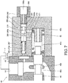
- the switching valve 260 has the switching spool 265 slidably inserted into a second accommodating hole 270 formed in the second cap 49b of the communication valve 40 and a plug 280 sealing the second accommodating hole 270.
- the switching pilot chamber 261 is defined between one end portion of the switching spool 265 and the plug 280.
- the switching spring 262 is provided in a compressed state in a spring accommodating chamber 270a defined between the other end portion of the switching spool 265 and a bottom part of the second accommodating hole 270.
- a first connection passage 271 allowing the second pilot chamber 41b and the second accommodating hole 270 to communicate and a second connection passage 272 allowing the spring accommodating chamber 270a and the tank T to communicate are formed in the second cap 49b.
- the second connection passage 272 communicates with the drain passage 14 through a third connection passage 273 formed in the valve housing 45 of the communication valve 40.
- the first connection passage 271, the second connection passage 272, and the third connection passage 273 constitute the tank passage 51 (see FIG. 6 ).
- a fourth connection passage 274 provided closer to the plug 280 side than the first connection passage 271 and allowing the second pilot chamber 41b and the second accommodating hole 270 to communicate is further formed in the second cap 49b.
- a pilot port 280a configured to introduce the control pilot pressure to the switching pilot chamber 261 of the switching valve 260 is formed in the plug 280.
- An annular first communication passage 265a, a second communication passage 265b as an internal passage allowing the first communication passage 265a and the spring accommodating chamber 270a to communicate, and an annular third communication passage 265c are formed in the switching spool 265.
- a shaft portion 267 supporting the switching spring 262 is provided on the end portion of the switching spool 265 faced with the spring accommodating chamber 270a.
- a slit 268 extending in the radial direction is formed on an end surface of the switching spool 265 faced with the plug 280.
- the switching valve 260 In a state where the control pilot pressure is not introduced to the switching pilot chamber 261 of the switching valve 260, the switching valve 260 is at the first communication position 260A.
- the second pilot chamber 41b communicates with the pilot port 280a through the fourth connection passage 274, the third communication passage 265c, the switching pilot chamber 261, and the slit 268.
- the second pilot chamber 41b communicates with the tank T through the pilot valve 27.
- the communication between the first connection passage 271 and the spring accommodating chamber 270a is shut off by the switching spool 265.
- the switching valve 260 When the control pilot pressure is introduced to the switching pilot chamber 261 of the switching valve 260, the switching valve 260 is switched to the holding position 260B. At the holding position 260B, the communication between the fourth connection passage 274 and the switching pilot chamber 261 is shut off by the switching spool 265, and the communication between the second pilot chamber 41b and the pilot port 280a is shut off. Moreover, at the holding position 260B, too, the communication between the first connection passage 271 and the spring accommodating chamber 270a is shut off by the switching spool 265. Thus, the communication between the second pilot chamber 41b of the communication valve 40 and the tank T is shut off by the switching valve 260.
- the switching spool 265 When the control pilot pressure introduced to the switching pilot chamber 261 becomes larger from the state at the holding position 260B, the switching spool 265 is moved to the left direction in the figure, and the switching valve 260 is switched to the second communication position 260C.
- the first connection passage 271 and the first communication passage 265a communicate, and the second pilot chamber 41b communicates with the drain passage 14 through the first connection passage 271, the first communication passage 265a, the second communication passage 265b, the spring accommodating chamber 270a, the second connection passage 272, and the third connection passage 273.
- the tank passage 51 is opened, and the working oil in the second pilot chamber 41b is discharged to the tank T.
- the switching valve 260 is operated in conjunction with the cylinder control valve 25 by the control pilot pressure operating the cylinder control valve 25 and is switched to the holding position 260B in an initial stage of switching of the cylinder control valve 25 to the operation position.
- the initial stage of switching of the cylinder control valve 25 to the operation position switching of the communication valve 40 to the supply position 40A before switching of the cylinder control valve 25 can be prevented.
- the switching valve 260 is switched from the holding position 260B to the second communication position 260C with the rise of the control pilot pressure.
- the communication valve 40 can be switched to the supply position 40A quickly by configuring such that the switching valve 260 is switched to the second communication position 260C immediately after the cylinder control valve 25 is switched to the operation position.
- the hydraulic cylinder 3 can be driven quickly during the complex operation.
- the switching valve 260 completely shuts off the tank passage 51 by the holding position 260B, switching of the communication valve 40 can be reliably prevented.
- the switching valve 260 allows the second pilot chamber 41b of the communication valve 40 and the tank T to communicate through the pilot port 280a formed in the plug 280 at the first communication position 260A. That is, when the switching valve 260 is at the first communication position 260A, the second pilot chamber 41b of the communication valve 40 does not communicate with the tank T through the tank passage 51 and the drain passage 14.
- the switching valve 260 may allow the second pilot chamber 41b of the communication valve 40 and the tank T to communicate through the tank passage 51 at either of the first communication position 260A and the second communication position 260C as illustrated in FIG. 8 .
- FIGs. 8 and 9 specific description will be made by referring to FIGs. 8 and 9 .
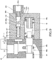
- the switching spool 265 according to the variation is configured so that the first connection passage 271 and the spring accommodating chamber 270a directly communicate with each other at the first communication position 260A. Moreover, in the switching spool 265 according to the variation, the third communication passage 265c and the fourth connection passage 274 are not formed. In such variation, the first connection passage 271 and the spring accommodating chamber 270a directly communicate with each other at the first communication position 260A, and the tank passage 51 is opened similarly at the second communication position 260C. When the switching valve 260 is switched to the holding position 260B, the direct communication between the first connection passage 271 and the spring accommodating chamber 270a is shut off by the switching spool 265.
- the communication between the first connection passage 271 and the first communication passage 265a is also shut off.
- the switching valve 260 is switched to the second communication position 260C, the first connection passage 271 and the first communication passage 265a communicate with each other similarly to the aforementioned third embodiment, and the second pilot chamber 41b communicates with the tank T. Even in such variation, the effects similar to those in the aforementioned third embodiment are exerted.
- the third communication passage 265c is formed in the switching spool 265 closer to the plug 280 side than the first communication passage 265a, and the fourth connection passage 274 is formed in the second cap 49b so as to communicate with the third communication passage 265c.
- the tank passage 51 is preferably configured to be opened in either one of the first communication position 260a and the second communication position 260c as in this variation.
- the switching valve 260 is operated in conjunction with the cylinder control valve 25 by the control pilot pressure operating the cylinder control valve 25 and is at the holding position 260B in the initial stage of switching of the cylinder control valve 25 to the extended position 25B or the contracted position 25C.
- the switching valve 260 is operated in conjunction with the cylinder control valve 25 by the control pilot pressure operating the cylinder control valve 25 and is at the holding position 260B in the initial stage of switching of the cylinder control valve 25 to the extended position 25B or the contracted position 25C.
- the communication valve 40 can be switched to the supply position 40A quickly by configuring the switching valve 260 such that the switching valve 260 is at the second communication position 260C immediately after the cylinder control valve 25 is switched to the extended position 25B or the contracted position 25C.
- the hydraulic cylinder 3 can be driven quickly during the complex operation.
- the switching valve 260 completely shuts off the tank passage 51 by the holding position 260B, switching of the communication valve 40 can be reliably prevented.
- the fluid pressure control device 100 has the first main passage 13 configured to introduce the working oil discharged from the first driving pump P1, the cylinder control valve 25 provided in the first main passage 13 and configured to control the flow of the working oil supplied and discharged to and from the hydraulic cylinder 3 configured to drive the load, the first merging passages 17 configured to introduce the working oil to the cylinder control valve 25 from the third driving pump P3, the communication valve 40 to which the first merging passage 17 is connected and having the first pilot chamber 41a to which the pilot passage 50 to which the pilot pressure is introduced is connected and the second pilot chamber 41b to which the tank passage 51 communicating with the tank T is connected.
- the first control passage 52a communicating with the tank T through the cylinder control valve 25 is connected to the pilot passage 50, the communication valve 40 has the supply position 40A where the working oil is introduced to the cylinder control valve 25 from the third driving pump P3 and the shut-off position 40B where the supply of the working oil to the cylinder control valve 25 from the third driving pump P3 is shut off in accordance with the pressure difference between the first pilot chamber 41a and the second pilot chamber 41b, the communication valve 40 is switched to the supply position 40A when the first control passage 52a is shut off by the cylinder control valve 25 so that the pilot pressure is introduced to the first pilot chamber 41a, and the resistance portion (the throttle portion 60, 160, the switching valve 260) configured to give the resistance to the passing working oil is provided in the tank passage 51.
- the communication valve 40 has the supply position 40A where the working oil is introduced to the cylinder control valve 25 from the third driving pump P3 and the shut-off position 40B where the supply of the working oil to the cylinder control valve 25 from the third driving pump P3 is shut off
- the resistance portion (the throttle portion 60, 160, the switching valve 260) is provided in the tank passage 51 allowing the second pilot chamber 41b of the communication valve 40 and the tank T to communicate, the timing when the position of the communication valve 40 is switched can be adjusted by adjusting the resistance applied by the resistance portion (the throttle portion 60, 160, the switching valve 260) to the flow of the working oil.
- the timing of switching of the cylinder control valve 25 and the communication valve 40 can be matched with accuracy, the rise of the load of each pump can be suppressed. Therefore, stability of the operation of the fluid pressure control device 100 is improved.
- the fluid pressure control device 100 further includes the first traveling control valve 20 provided in the first main passage 13 on the upstream of the cylinder control valve 25 and configured to control the flow of the working oil supplied and discharged to and from the first traveling motor 1, the second control passage 52b communicating with the tank T through the traveling control valve 20 is connected to the pilot passage 50, and when the first control passage 52a is shut off by the cylinder control valve 25 and the second control passage 52b is shut off by the traveling control valve 20, the pilot pressure is introduced to the first pilot chamber 42a, and the communication valve 40 is switched to the supply position 40A.
- the resistance portion is the throttle portions 60 and 160 throttling the flow passage of the tank passage 51.
- the throttle portion 160 is a variable throttle configured such that the resistance applied to the flow of the working oil is made smaller when the communication valve 40 is switched from the shut-off position 40B to the supply position 40A.
- the communication valve 40 can be switched to the supply position 40A quickly after the cylinder control valve 25 is switched so as to supply and discharge the working oil to and from the hydraulic cylinder 3, and the complex operation can be performed quickly.
- the resistance portion is the switching valve 260 to which the control pilot pressure operating the cylinder control valve 25 is introduced and operated by the control pilot pressure.
- the switching valve 260 has the first communication position 260A where the second pilot chamber 41a of the communication valve 40 communicates with the tank T, the control position (holding position 260B) switched by the increase in the control pilot pressure from the state at the first communication position 260A and applying the resistance to the working fluid flowing through the tank passage 51, and the second communication position 260C switched by the increase in the control pilot pressure from the state at the control position (holding position 260B) and allowing the second pilot chamber 41b and the tank T to communicate with each other.
- the communication valve 40 can be switched to the supply position 40A quickly after the cylinder control valve 25 is switched so as to supply and discharge the working oil to and from the hydraulic cylinder 3, and the complex operation can be performed quickly.
- the switching valve 260 opens the tank passage 51 and allows the second pilot chamber 41b and the tank T to communicate with each other at the first communication position 260A and opens the tank passage 51 and allows the second pilot chamber 41b and the tank T to communicate with each other at the second communication position 260C.
- the switching valve 260 has the switching pilot chamber 261 to which the control pilot pressure is introduced and the pilot port 280a which introduces the control pilot pressure to the switching pilot chamber 261, and at the first communication position 260A, the second pilot chamber 41b and the tank passage 51 are made to communicate through the pilot port 280a, and at the second communication position 260C, the tank passage 51 is opened, and the second pilot chamber 41b and the tank T are made to communicate with each other.
Landscapes
- Engineering & Computer Science (AREA)
- General Engineering & Computer Science (AREA)
- Mining & Mineral Resources (AREA)
- Civil Engineering (AREA)
- Structural Engineering (AREA)
- Physics & Mathematics (AREA)
- Fluid Mechanics (AREA)
- Mechanical Engineering (AREA)
- Operation Control Of Excavators (AREA)
- Fluid-Pressure Circuits (AREA)
Abstract
Description
- The present invention relates to a fluid pressure control device.
-
JP2014-122644A JP2014-122644A - In this hydraulic circuit, a pilot line communicating with a pilot hydraulic pressure source is connected to a second pilot port of the merging valve. A first side bypass line is connected to the pilot line. The first side bypass line passes through a sub valve provided integrally with an arm directional switching valve and is connected to a drain line communicating with a tank on a downstream side thereof.
- In the hydraulic circuit disclosed in
JP2014-122644A - As described above, in the aforementioned hydraulic circuit, in the case where a flow rate of the working oil to the arm hydraulic cylinder is insufficient such as during a complex operation when the arm is operated during running of a vehicle, for example, the working oil is supplied from the third pump to the arm hydraulic cylinder in conjunction between the arm directional switching valve and the merging valve. As a result, shortage of the flow rate of the working oil supplied to the arm hydraulic cylinder is prevented.
- However, in such hydraulic circuit, since a space where oil passages and ports are formed is limited, there is limitation on shapes and arrangement of the oil passages and the ports. Thus, it is difficult to match timing when the arm directional switching valve is switched with timing when the merging valve is switched with accuracy.
- Moreover, supply and discharge of the working oil to and from the arm hydraulic cylinder is controlled by the arm directional switching valve. Thus, if the merging valve is switched so that the working oil is supplied from the third pump to the arm hydraulic cylinder before the arm directional switching valve is switched and the supply of the working oil to the arm hydraulic cylinder is allowed, there is a concern that a load of the third pump increases.
- The present invention has an object to improve stability of the operation of the fluid pressure control device.
- According to one aspect of the present invention, a fluid pressure control device includes: a main passage configured to introduce a working fluid discharged from a first pump; a cylinder control valve provided in the main passage, the cylinder control valve being configured to control a flow of the working fluid supplied to and discharged from a fluid pressure cylinder configured to drive a load; a merging passage configured to introduce the working fluid to the cylinder control valve from a second pump; and a communication valve to which the merging passage is connected, the communication valve having a first pilot chamber to which a pilot passage to which a pilot pressure is introduced is connected and a second pilot chamber to which a tank passage communicating with a tank is connected. A first control passage communicating with the tank through the cylinder control valve is connected to the pilot passage. The communication valve has a supply position where the working fluid is introduced to the cylinder control valve from the second pump and a shut-off position where a supply of the working fluid to the cylinder control valve from the second pump is shut off, and when the first control passage is shut off by the cylinder control valve so that pilot pressure is introduced to the first pilot chamber and the communication valve is switched to the supply position. A resistance portion configured to be applying resistance to the passing working fluid is provided in the tank passage.
-
-
FIG. 1 is a schematic diagram illustrating configuration of a fluid pressure control device according to a first embodiment of the present invention; -
FIG. 2 is a sectional view of a communication valve according to the first embodiment of the present invention and is a view illustrating a state at a shut-off position; -
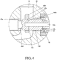
FIG. 3 is an enlarged sectional view of the communication valve according to a second embodiment of the present invention and is a view illustrating a periphery of a tank passage and a throttle portion; -
FIG. 4 is an enlarged sectional view of the communication valve according to a first variation of the second embodiment of the present invention and is a view corresponding toFIG. 3 ; -
FIG. 5 is an enlarged sectional view of the communication valve according to a second variation of the second embodiment of the present invention and is a view corresponding toFIG. 3 ; -
FIG. 6 is a schematic diagram illustrating configuration of the fluid pressure control device according to a third embodiment of the present invention; -
FIG. 7 is an enlarged sectional view illustrating the communication valve and a switching valve according to the third embodiment of the present invention and is a view illustrating a state where the switching valve is at a first communication position; -
FIG. 8 is a schematic diagram illustrating configuration of the fluid pressure control device according to a variation of the third embodiment of the present invention; and -
FIG. 9 is an enlarged sectional view illustrating the communication valve and the switching valve according to the variation of the third embodiment of the present invention and is a view illustrating a state where the switching valve is at the first communication position. - Hereinafter, a fluid
pressure control device 100 according to a first embodiment of the present invention will be described by referring to the attached drawings. In the following, the fluidpressure control device 100 provided in a fluidpressure control system 101 that is used for a construction machine or particularly for a hydraulic excavator and that controls a flow of a working fluid supplied and discharged to and from a fluid pressure actuator will be described as an example. - First, entire configuration of the fluid
pressure control system 101 including the fluidpressure control device 100 will be described by referring toFIG. 1 . - The fluid
pressure control system 101 includes a plurality of hydraulic pumps P1, P2, and P3 discharging working oil as the working fluid, a tank T storing the working oil, a first travelingmotor 1 and a second travelingmotor 2 configured to drive a pair of crawler-type right and left traveling devices (not shown), ahydraulic cylinder 3 as a fluid pressure cylinder configured to drive a driving target (not shown) such as a boom, an arm or a bucket, and a fluidpressure control device 100 configured to control operations of thefirst traveling motor 1, the second travelingmotor 2, and thehydraulic cylinder 3. In the following, a case where thehydraulic cylinder 3 drives the boom will be described as an example, and illustration and detailed description of the hydraulic cylinder configured to drive the driving target other than the boom will be omitted. - The fluid
pressure control system 101 includes three hydraulic pumps, that is, a first driving pump P1 as a first pump, a second driving pump P2, and a third driving pump P3 as a second pump. The first driving pump P1, the second driving pump P2, and the third driving pump P3 are driven by an engine (not shown) or a motor (not shown) and discharge the working oil. - The working oil is supplied to and discharged from the first traveling
motor 1 through a first supply anddischarge passage 10a and a second supply anddischarge passage 10b. The working oil is supplied to the first travelingmotor 1 from the first supply anddischarge passage 10a, and thefirst traveling motor 1 is rotated forward by discharge of the working oil through a second supply anddischarge passage 10b. The working oil is supplied to the first travelingmotor 1 from the second supply anddischarge passage 10b, and thefirst traveling motor 1 is rotated backward by discharge of the working oil through the first supply anddischarge passage 10a. Similarly, the working oil is supplied and discharged to and from the second travelingmotor 2 through a third supply anddischarge passage 11a and a fourth supply anddischarge passage 11b. The working oil is supplied to the second travelingmotor 2 from the third supply anddischarge passage 11a, and the second travelingmotor 2 is rotated forward by discharge of the working oil through the fourth supply anddischarge passage 11b. The working oil is supplied to the second travelingmotor 2 from the fourth supply anddischarge passage 11b, and the second travelingmotor 2 is rotated backward by discharge of the working oil through the third supply anddischarge passage 11a. - The
hydraulic cylinder 3 is a double-acting cylinder having apiston 5 dividing an inside of acylinder tube 4 into a rod-side chamber 7 and a bottom-side chamber 8. Apiston rod 6 is connected to thepiston 5. The working oil is supplied and discharged to and from the rod-side chamber 7 of thehydraulic cylinder 3 through a rod-side passage 12a. The working oil is supplied and discharged to and from the bottom-side chamber 8 of thehydraulic cylinder 3 through a bottom-side passage 12b. - Since the working oil is supplied to the bottom-
side chamber 8, and the working oil is discharged from the rod-side chamber 7, thehydraulic cylinder 3 is extended and raises the boom. On the contrary, since the working oil is supplied to the rod-side chamber 7, and the working oil is discharged from the bottom-side chamber 8, thehydraulic cylinder 3 is contracted and lowers the boom. - Subsequently, specific configuration of the fluid
pressure control device 100 will be described. - The fluid
pressure control device 100 includes a first circuit system C1 connected to the first driving pump P1 and to which the working oil is supplied from the first driving pump P1, a second circuit system C2 connected to the second driving pump P2 and to which the working oil is supplied from the second driving pump P2, and a third circuit system C3 connected to the third driving pump P3 and to which the working oil is supplied from the third driving pump P3. - The first circuit system C1 includes a first
main passage 13 configured to introduce the working oil discharged from the first driving pump P1, a firsttraveling control valve 20 provided in the firstmain passage 13 and configured to control a flow of the working oil supplied and discharged to and from the first travelingmotor 1, and acylinder control valve 25 provided in the firstmain passage 13 on the downstream of the fisttraveling control valve 20 and configured to control the flow of the working oil supplied and discharged to and from thehydraulic cylinder 3. - The first
main passage 13 is connected to adrain passage 14 communicating with the tank T and introduces the working oil discharged from the first driving pump P1 to the tank T. - The first
traveling control valve 20 has aneutral position 20A where the firstmain passage 13 is opened, aforward rotation position 20B where thefirst traveling motor 1 is rotated forward, and abackward rotation position 20C where the first travelingmotor 1 is rotated backward. The firsttraveling control valve 20 is switched to theforward rotation position 20B when a pilot pressure is introduced to onepilot pressure chamber 21a and is switched to thebackward rotation position 20C when the pilot pressure is introduced to theother pilot chamber 21b. In a state where the pilot pressure is not introduced to neither of the pair of thepilot chambers traveling control valve 20 is maintained at theneutral position 20A by a pair of centeringsprings 22a and 22b. - In a state where the first
traveling control valve 20 is at theneutral position 20A, the first supply anddischarge passage 10a and the second supply anddischarge passage 10b connected to thefirst traveling motor 1 communicate with a firstdrain merging passage 14a merging into thedrain passage 14, respectively. Thus, the working oil is not supplied and discharged to and from the first travelingmotor 1, and it is not rotated. Moreover, abranch passage 13a branching from the firstmain passage 13 is connected to the firsttraveling control valve 20. In the state where the firsttraveling control valve 20 is at theneutral position 20A, the firstmain passage 13 is opened, and thebranch passage 13a is shut off. - When the first
traveling control valve 20 is switched to theforward rotation position 20B, the firstmain passage 13 is shut off, and the working oil is introduced to the first travelingmotor 1 through thebranch passage 13a and the first supply anddischarge passage 10a. Moreover, the working oil is discharged from the first travelingmotor 1 through the second supply anddischarge passage 10b and the firstdrain merging passage 14a. Thus, when the firsttraveling control valve 20 is switched to theforward rotation position 20B, the first travelingmotor 1 is rotated forward. - When the first
traveling control valve 20 is switched to thebackward rotation position 20C, the firstmain passage 13 is shut off, and the working oil is introduced to the first travelingmotor 1 through thebranch passage 13a and the second supply anddischarge passage 10b, and the working oil is discharged through the first supply anddischarge passage 10a and the firstdrain merging passage 14a. As described above, when the firsttraveling control valve 20 is switched to thebackward rotation position 20C, the first travelingmotor 1 is rotated backward. - The
cylinder control valve 25 has aneutral position 25A where the firstmain passage 13 is opened, anextended position 25B where thehydraulic cylinder 3 is extended, and acontracted position 25C where thehydraulic cylinder 3 is contracted. In the following, theextended position 25B and the contractedposition 25C are combined and also called an "operation position". - The
cylinder control valve 25 is operated when the pilot pressure (a "control pilot pressure" which will be described later) is introduced to a pair ofpilot chambers pilot valve 27 from a pilot pump PP. Thepilot valve 27 introduces the pilot pressure to either one of the pair ofpilot chambers - The
cylinder control valve 25 is switched to theextended position 25B when the pilot pressure is introduced to the onepilot chamber 26a and is switched to the contractedposition 25C when the pilot pressure is led to theother pilot chamber 26b. In a state where the pilot pressure is not introduced to neither of the pair ofpilot chambers cylinder control valve 25 is maintained at theneutral position 25A by a pair of centeringsprings - In a state where the
cylinder control valve 25 is at theneutral position 25A, the rod-side passage 12a and the bottom-side passage 12b connected to thehydraulic cylinder 3 do not communicate and with thebranch passage 13b branching from the firstmain passage 13 between them and the firsttraveling control valve 20 and they are shut off, respectively. Moreover, at theneutral position 25A, the rod-side passage 12a and the bottom-side passage 12b do not communicate with the seconddrain merging passage 14b merging with thedrain passage 14 and they are shut off, respectively. As a result, thehydraulic cylinder 3 has supply and discharge of the working oil shut off and is brought into a load holding state. - When the
cylinder control valve 25 is switched to theextended position 25B, the firstmain passage 13 is shut off, and in thehydraulic cylinder 3, the working oil is introduced to the bottom-side chamber 8 through thebranch passage 13b and the bottom-side passage 12b. Moreover, the working oil in the rod-side chamber 7 is discharged to the tank T through the rod-side passage 12a and the seconddrain merging passage 14b. As described above, when thecylinder control valve 25 is switched to theextended position 25B, thehydraulic cylinder 3 is extended. - When the
cylinder control valve 25 is switched to the contractedposition 25C, the firstmain passage 13 is shut off, and in thehydraulic cylinder 3, the working oil is introduced to the rod-side chamber 7 through thebranch passage 13b and the rod-side passage 12a. Moreover, the working oil of the bottom-side chamber 8 is discharged to the tank T through the bottom-side passage 12b and the seconddrain merging passage 14b. As described above, when thecylinder control valve 25 is switched to the contractedposition 25C, thehydraulic cylinder 3 is contracted. - The second circuit system C2 includes a second
main passage 15 configured to introduce the working oil discharged from the second driving pump P2, a secondtraveling control valve 30 provided in the secondmain passage 15 and configured to control a flow of the working oil supplied and discharged to and from the second travelingmotor 2, and acontrol valve 31 provided in the secondmain passage 15 on the downstream of the secondtraveling control valve 30 and configured to control the flow of the working oil supplied and discharged to and from the hydraulic cylinder driving a load different from the boom. Since the second circuit system C2 has constitution similar to that of the first circuit system C1, detailed illustration and description will be omitted. Thecontrol valve 31 of the second circuit system C2 has constitution similar to that of thecylinder control valve 25 and controls the operation of the hydraulic cylinder similarly to thecylinder control valve 25. Thus, detailed illustration and description of thecontrol valve 31 will be also omitted. A plurality of thecontrol valves 31 may be provided in accordance with the number of hydraulic cylinders in the second circuit system C2. - The third circuit system C3 includes a
pump passage 16 configured to introduce the working oil discharged from the third driving pump P3, acommunication valve 40 provided in thepump passage 16, and acontrol valve 44 provided in thepump passage 16 on the downstream of thecommunication valve 40 and configured to control the flow of the working oil supplied and discharged to and from the hydraulic cylinder driving the load different from the boom. - The
pump passage 16 communicates with the tank T and introduces the working oil discharged from the third driving pump P3 to the tank T. Moreover, arelief passage 16e communicating with the tank T through thedrain passage 14 is connected to thepump passage 16 on the upstream of thecommunication valve 40. Arelief valve 43 is provided in therelief passage 16e. Since thecontrol valve 44 in the third circuit system C3 has constitution similar to that of thecylinder control valve 25 in the first circuit system C1, detailed illustration and description will be omitted. - Here, in a working machine, a complex operation in which the boom is driven, for example, during traveling of a vehicle with the first and
second traveling motors traveling control valve 20 is at theforward rotation position 20B or thebackward rotation position 20C during traveling of the vehicle, themain passage 13 is shut off by the firsttraveling control valve 20. Thus, during traveling of the vehicle, supply of the working oil from the first driving pump P1 through the firstmain passage 13 to thecylinder control valve 25 on the downstream of the firsttraveling control valve 20 is shut off. As a result, the flow rate of the working oil for operating thehydraulic cylinder 3 runs short. - Thus, in order to perform the aforementioned complex operation, the working oil is supplied by the
communication valve 40 from the third driving pump P3 to thecylinder control valve 25 in the fluidpressure control device 100. Hereinafter, constitution and operations of thecommunication valve 40 will be described. In the following, a case of the complex operation of thehydraulic cylinder 3 for driving the boom in which the operation is controlled by the first circuit system C1 will be described as an example. Since the constitution similar to the case of the first circuit system C1 can be applied to the complex operation with the hydraulic cylinder in which the operation is controlled by the second circuit system C2, description will be omitted as appropriate. Moreover, in the following, the firsttraveling control valve 20 is also called simply as the "travelingcontrol valve 20" and the first travelingmotor 1 simply as the "travelingmotor 1". - First, constitution of the
communication valve 40 will be described by referring toFIG. 1 . - A first merging
passage 17 configured to introduce the working oil to thecylinder control valve 25 from the third driving pump P3 is connected to thecommunication valve 40. Thefirst merging passage 17 communicates with thebranch passage 13b branching from the firstmain passage 13 between the travelingcontrol valve 20 and thecylinder control valve 25. - Moreover, a
branch passage 19 branching from thepump passage 16 and asecond merging passage 18 configured to introduce the working oil to thecontrol valve 31 of the second circuit system C2 from the third driving pump P3 are connected to thecommunication valve 40. - The
communication valve 40 has its position switched by movement of a spool 46 (seeFIG. 2 ) which will be described later. Thecommunication valve 40 has asupply position 40A where the working oil is introduced to thecylinder control valve 25 from the third driving pump P3 and a shut-offposition 40B where the supply of the working oil to thecylinder control valve 25 from the third driving pump P3 is shut off. Thebranch passage 19 is not shut off even if thecommunication valve 40 is at either one of thesupply position 40A and the shut-offposition 40B and introduces the working oil of the third driving pump P3 to thecontrol valve 44 of the third circuit system C3. - Moreover, the
communication valve 40 has afirst pilot chamber 41a, asecond pilot chamber 41b, and aspring 42 as a biasing member. Thecommunication valve 40 is operated in accordance with a pressure difference between thefirst pilot chamber 41a and thesecond pilot chamber 41b. - A
pilot passage 50 is connected to thefirst pilot chamber 41a, and the pilot pressure is introduced thereto through thepilot passage 50. The pilot pressure introduced to thefirst pilot chamber 41a acts on thespool 46 so that thecommunication valve 40 is switched to thesupply position 40A. - A
tank passage 51 communicating with the tank T is connected to thesecond pilot chamber 41b. Thus, thesecond pilot chamber 41b is filled with the working oil with a pressure according to an internal pressure of the tank T. The pressure of thesecond pilot chamber 41b acts on thespool 46 so as to resist the pressure of thefirst pilot chamber 41a. Moreover, athrottle portion 60 as a resistance portion applying resistance to the passing working oil is provided in thetank passage 51. - The
spring 42 biases thespool 46 so that thecommunication valve 40 is switched to the shut-offposition 40B. Thus, in a state where the pilot pressure is not introduced to thefirst pilot chamber 41a, thecommunication valve 40 is at the shut-offposition 40B. - A
first control passage 52a and asecond control passage 52b are connected to thepilot passage 50 communicating with thefirst pilot chamber 41a through acommon passage 52. Thefirst control passage 52a communicates with the tank T through thecylinder control valve 25. Moreover, thesecond control passage 52b communicates with the tank T through the firsttraveling control valve 20 and the secondtraveling control valve 30. Since thefirst control passage 52a connected to thepilot passage 50 is connected to thecylinder control valve 25, and thesecond control passage 52b is connected to the firsttraveling control valve 20, thecommunication valve 40 can be interlocked with the firsttraveling control valve 20 and thecylinder control valve 25. The operation of thecommunication valve 40 will be described later in detail. In addition to connection of thefirst control passage 52a to thecylinder control valve 25 of the first circuit system C1, it may be also configured to communicate with the tank T through thecontrol valve 31 of the second circuit system C2. - Hereinafter, specific configuration of the
communication valve 40 will be described by referring toFIG. 2 . InFIG. 2 , the constitutions similar to those inFIG. 1 are given the similar reference numerals, and description will be omitted as appropriate. Moreover, for convenience of description, as illustrated inFIG. 1 , description will be made with thepump passage 16 on the upstream of thecommunication valve 40 as an "upstream pump passage 16a" and thepump passage 16 on the downstream as a "downstream pump passage 16b". - The
communication valve 40 includes avalve housing 45 in which a firstaccommodating hole 45a is formed, thespool 46 slidably inserted into the firstaccommodating hole 45a and configured to switch a position, and afirst cap 49a and asecond cap 49b mounted on thevalve housing 45 and accommodating both ends of thespool 46 as illustrated inFIG. 2 . - A pair of
upstream ports 16c communicating with theupstream pump passage 16a, adownstream port 16d communicating with thedownstream pump passage 16b, a first mergingport 17a communicating with the first mergingpassage 17, a second mergingport 18a communicating with thesecond merging passage 18, and acommon port 52c communicating with thecommon passage 52 are formed so as to open in the firstaccommodating hole 45a in thevalve housing 45. Moreover, a part of thebranch passage 19 communicating with theupstream pump passage 16a and a part of thedrain passage 14 communicating with the firstaccommodating hole 45a are formed in thevalve housing 45. - A
bulkhead portion 45b in which a part of the firstaccommodating hole 45a into which thespool 46 is inserted is formed is provided in thedrain passage 14. Thedrain passage 14 is made to partially branch to two parts by thebulkhead portion 45b. - A first
annular groove 46a, a secondannular groove 46b, a thirdannular groove 46c, and a fourthannular groove 46d are arranged side by side from one end side (left side inFIG. 2 ) to the other end side (right side inFIG. 2 ) in the axial direction in an outer peripheral surface of thespool 46. - The
first pilot chamber 41a is defined between thefirst cap 49a and the one end portion of thespool 46. Apilot port 49c communicating with thepilot passage 50 is formed in thefirst cap 49a. Thefirst pilot chamber 41a communicates with thepilot port 49c of thefirst cap 49a through anorifice 50a. Moreover, a firstinternal passage 47 allowing thefirst pilot chamber 41a and the secondannular groove 46b to communicate with each other is formed in thespool 46. Thefirst pilot chamber 41a communicates with thecommon port 52c at all times through the firstinternal passage 47 and the secondannular groove 46b. - The
second pilot chamber 41b is defined between thesecond cap 49b and the other end portion of thespool 46. Thespring 42 is provided in a compressed state between the second cap 49 and the other end of thespool 46 and biases thespool 46 in a direction in which thesecond pilot chamber 41b is extended. - The
second pilot chamber 41b communicates with thedrain passage 14 at all times through a secondinternal passage 48 formed on the other end of thespool 46. The secondinternal passage 48 has anaxial passage 48a opened in thesecond pilot chamber 41b and extending in the axial direction of thespool 46 and aradial passage 48b opened in the fourthannular groove 46d of thespool 46 and communicating with theaxial passage 48a. The secondinternal passage 48 corresponds to thetank passage 51 illustrated inFIG. 1 . - A part of the
radial passage 48b is formed as an orifice and constitutes the throttle portion 60 (seeFIG. 1 ). Theradial passage 48b communicates with thedrain passage 14 through the fourthannular groove 46d and the firstaccommodating hole 45a of thebulkhead portion 45b regardless of a position of thespool 46. Thus, thethrottle portion 60 provided in theradial passage 48b functions as a fixed throttle configured to give resistance according to its flow passage area to the flow of the working oil regardless of the position of thespool 46. - Subsequently, the operation of the
communication valve 40 will be specifically described by referring toFIGs. 1 and2 . - When the traveling control valve 20 (and the second traveling control valve 30) is at the
neutral position 20A, as illustrated inFIG. 1 , thesecond control passage 52b communicates with the tank T. When the travelingcontrol valve 20 is switched to theforward rotation position 20B or thebackward rotation position 20C, the communication between thesecond control passage 52b and the tank T is shut off by the travelingcontrol valve 20 and is closed without communicating with another passage or the like. Though illustration and detailed description are omitted, when the secondtraveling control valve 30 of the second circuit system C2 is switched to the operation position, thesecond control passage 52b is also shut off. - Similarly, the
first control passage 52a communicates with the tank T when thecylinder control valve 25 is at theneutral position 25A. When thecylinder control valve 25 is switched to the operation position (either one of theextended position 25B and the contractedposition 25C), the communication between thefirst control passage 52a and the tank T is shut off by thecylinder control valve 25 and is closed without communicating with another passage or the like. - Thus, in a state where at least either one of the traveling
control valve 20 and thecylinder control valve 25 is at theneutral position motor 1 and thehydraulic cylinder 3 is not operated), the pilot pressure of thepilot passage 50 is introduced to the tank T through thesecond control passage 52b and/or thefirst control passage 52a. Thus, thecommunication valve 40 is at the shut-offposition 40B by a biasing force of thespring 42. - When the
communication valve 40 is at the shut-offposition 40B, as illustrated inFIG. 2 , one of theupstream ports 16c and thedownstream port 16d communicate with each other through the thirdannular groove 46c. As a result, theupstream pump passage 16a and thedownstream pump passage 16b communicate with each other, and thepump passage 16 is opened. Moreover, the communication between the pair ofupstream ports 16c and the first and second mergingports spool 46. - During the complex operation in which the traveling
control valve 20 is switched to theforward rotation position 20B or thebackward rotation position 20C, and thecylinder control valve 25 is switched to theextended position 25B or the contractedposition 25C, the communication between thefirst control passage 52a and the tank T and the communication between thesecond control passage 52b and the tank T are shut-off, respectively. Thus, the pilot pressure of thepilot passage 50 is introduced to thefirst pilot chamber 41a of thecommunication valve 40. - When the pilot pressure is introduced to the
first pilot chamber 41a, thespool 46 is moved to the right direction inFIG. 2 so that a capacity of thefirst pilot chamber 41a is enlarged, and the working oil of thesecond pilot chamber 41b is discharged to the tank T through thethrottle portion 60 of theradial passage 48b (tank passage 51) and thedrain passage 14. As a result, thecommunication valve 40 is switched to thesupply position 40A. - At the
supply position 40A, the oneupstream port 16c and the first mergingport 17a communicate with each other through the thirdannular groove 46c, and the otherupstream port 16c and the second mergingport 18a communicate with each other through the firstannular groove 46a. Thus, theupstream pump passage 16a and the first mergingpassage 17 communicate with each other, and theupstream pump passage 16a and thesecond merging passage 18 communicate with each other. Moreover, at thesupply position 40A, the communication between theupstream pump passage 16a and thedownstream pump passage 16b is shut off by thespool 46. - As a result, since the working oil in the third driving pump P3 is introduced to the
cylinder control valve 25 through the first mergingpassage 17, the complex operation in which the travelingmotor 1 and thehydraulic cylinder 3 driving the boom are driven at the same time is made possible. - As described above, the
communication valve 40 is switched in accordance with the switching of the travelingcontrol valve 20 and thecylinder control valve 25. However, in the fluid pressure control device in general, spaces for forming each passage and ports in the valve housing are limited, and the shape and layout of the passages are also limited in accordance with that. Thus, it is difficult to match the timing when the traveling control valve and the cylinder control valve are switched with the timing when the communication valve is switched with accuracy by the change in the shape or the layout of the passages and the like. - When the boom is to be operated during traveling of the vehicle, for example, if the communication valve is switched to the supply position A before the cylinder control valve is switched to the operation position, and the supply of the working oil to the hydraulic cylinder is allowed, the working oil is introduced to the first merging passage from the third driving pump. However, since the working oil cannot be supplied to the hydraulic cylinder, a load of the third driving pump rises. As a result, horse power control of the first and second driving pumps are performed together with the third driving pump, and discharge capacities are decreased, and there is a concern that a traveling speed of the vehicle is lowered.
- On the other hand, in the fluid
pressure control device 100, thethrottle portion 60 is provided in theradial passage 48b (tank passage 51) communicating with thesecond pilot chamber 41b. The position of thecommunication valve 40 is switched in accordance with resistance of the working oil applied by thethrottle portion 60. Thus, by adjusting the resistance applied by thethrottle portion 60 or more specifically, an orifice diameter, the timing when thecommunication valve 40 is switched can be adjusted. That is, as compared with a case where thethrottle portion 60 is not provided, the timing of switching to thesupply position 40A can be delayed in accordance with resistance applied by thethrottle portion 60. As a result, the timing can be substantially matched with the timing when thecylinder control valve 25 is switched. Therefore, switching of thecommunication valve 40 to thesupply position 40A before the switching of thecylinder control valve 25 can be prevented, and rise of the load of the third driving pump P3 and lowering of the traveling speed during the complex operation can be prevented. In order to prevent the rise of the load of the third driving pump P3 and the lowering of the traveling speed during the complex operation, it only needs to be configured such that thecommunication valve 40 is switched to thesupply position 40A at least after thecylinder control valve 25 is switched to the operation position, and it is not limited to complete matching of the switching timing of the both. - Subsequently, a variation of this embodiment will be described. The variation as follows is also within the range of the present invention, and it is possible to combine the following variations with each constitution of the aforementioned embodiment or to combine the following variation with another embodiment and its variation which will be described later and to combine the following variations with each other. Moreover, the variation described in the description of the aforementioned embodiment can be also similarly combined with other variations and other embodiments.
- In the aforementioned embodiment, the case where the working oil is introduced to the
cylinder control valve 25 from the third driving pump P3 during the complex operation in which the boom is operated during traveling of the vehicle is described. Not limited to that, in cases other than the case during the complex operation, it may be so configured that the working oil is introduced to thecylinder control valve 25 from the third driving pump P3 in order to compensate for shortage in the flow rate of the working oil supplied to thehydraulic cylinder 3. For example, thesecond control passage 52b in the aforementioned embodiment may be connected to a cylinder control valve (not shown) configured to control the hydraulic cylinder configured to operate those other than the boom (an arm, for example). In this case, when the boom and the arm are operated at the same time, the working oil is introduced to thecylinder control valve 25 from the third driving pump P3, and the shortage in the flow rate of the working oil is prevented. Moreover, it may be so configured that thesecond control passage 52b is eliminated, thecommunication valve 40 is made to be interlocked with the singlecylinder control valve 25, and the working oil is introduced to thecylinder control valve 25 from the third driving pump P3. As described above, it only needs to be configured such that thecommunication valve 40 introduces the working oil of the third driving pump P3 to thecylinder control valve 25 in conjunction with at least onecylinder control valve 25. - According to the aforementioned embodiment, the following effects are exerted.
- In the fluid
pressure control device 100, thethrottle portion 60 is provided in thetank passage 51 which allows thesecond pilot chamber 41b of thecommunication valve 40 to communicate with the tank T. Thus, the timing when the position of thecommunication valve 40 is switched can be adjusted by adjusting resistance that thethrottle portion 60 gives to the flow of the working fluid. Thus, since the timing of switching of thecylinder control valve 25 and thecommunication valve 40 can be matched with each other with accuracy, lowering of the traveling speed of the vehicle can be prevented by suppressing the rise of the load of each pump. Therefore, the operation of the fluidpressure control device 100 is made stable. - Subsequently, a second embodiment of the present invention will be described by referring to
FIGs. 3 to 5 . In the following, points different from the first embodiment will be mainly described, and the same reference numerals are given to the same constitutions as those in the aforementioned first embodiment, and description will be omitted. - In the aforementioned first embodiment, the
throttle portion 60 provided in thetank passage 51 is a fixed throttle. On the other hand, in the second embodiment, athrottle portion 160 is different from the aforementioned first embodiment in a point that thethrottle portion 160 is a variable throttle by which a flow passage area is changed in accordance with the position of thespool 46 of thecommunication valve 40. Hereinafter, the second embodiment will be described. - As illustrated in
FIG. 3 , in the second embodiment, the secondinternal passage 48 of thespool 46 has theaxial passage 48a communicating with thesecond pilot chamber 41b and two radial passages (hereinafter, called a "first passage 148a" and a "second passage 148b", respectively.) communicating with theaxial passage 48a. Thefirst passage 148a and thesecond passage 148b are formed so as to be separated from each other in the axial direction of thespool 46. Parts of thefirst passage 148a and thesecond passage 148b are formed asorifices orifices first passage 148a and thesecond passage 148b constitute thethrottle portion 160 as a variable throttle. - In the second embodiment, the
spool 46 is slidably inserted into the firstaccommodating hole 45a provided in thebulkhead portion 45b. - In a state where the pilot pressure is not introduced to the
first pilot chamber 41a, and thecommunication valve 40 is at the shut-offposition 40B, as illustrated inFIG. 3 , an opening portion of thefirst passage 148a is closed by an inner peripheral surface of thebulkhead portion 45b, and an opening portion of thesecond passage 148b is closed by the inner peripheral surface of thebulkhead portion 45b only partially. Thus, in this state, thesecond pilot chamber 41b communicates with thedrain passage 14 through thesecond passage 148b, and resistance according to the flow passage area of theorifice 160b of thesecond passage 148b is applied to the flow of the working oil discharged to thedrain passage 14 from thesecond pilot chamber 41b. - When the
spool 46 is moved to the right direction in the figure by the pilot pressure of thefirst pilot chamber 41a, in addition to thesecond passage 148b, thefirst passage 148a also communicates with thedrain passage 14. Thus, in this state, thesecond pilot chamber 41b communicates with thedrain passage 14 through thefirst passage 148a and thesecond passage 148b. As a result, the resistance according to the sum of the flow passage areas of theorifice 160a of thefirst passage 148a and theorifice 160b of thesecond passage 148b is applied to the flow of the working oil discharged to thedrain passage 14 from thesecond pilot chamber 41b. That is, in this state, since the flow passage resistance for two orifices is obtained, the resistance applied to the flow of the working oil is smaller than the case of the communication with thedrain passage 14 only through thesecond passage 148b. - As described above, in this embodiment, immediately after the switching from the shut-off
position 40B to thesupply position 40A, only thesecond passage 148b communicates with thedrain passage 14, and relatively large resistance is applied to the working oil flowing through the second internal passage 48 (tank passage 51). When thespool 46 is moved only for a predetermined amount after that, both thefirst passage 148a and thesecond passage 148b communicate with thedrain passage 14, and relatively small resistance is applied to the working oil flowing through thetank passage 51. As described above, the variable throttle in which the resistance applied to the flow of the working oil is changed in accordance with a stroke of thespool 46 is constituted by the twoorifices first passage 148a and thesecond passage 148b. - According to this embodiment, similarly to the aforementioned first embodiment, the timing when the
communication valve 40 is switched to thesupply position 40A can be delayed in accordance with the resistance applied by thethrottle portion 160, and switching of thecommunication valve 40 to thesupply position 40A before the switching of thecylinder control valve 25 can be prevented. - Moreover, in the fluid
pressure control device 100, when thecylinder control valve 25 is switched to the operation position, and thebranch passage 13b communicates with either one of the bottom-side passage 12b and the rod-side passage 12a during the complex operation, thecommunication valve 40 is preferably switched to thesupply position 40A quickly. However, since thethrottle portion 60 is a fixed throttle in the aforementioned first embodiment, relatively large resistance is applied to the working oil flowing through thetank passage 51 even after thecylinder control valve 25 is switched to the operation position. That is, even after thecylinder control valve 25 is switched to the operation position, the state where thecommunication valve 40 is not switched to thesupply position 40A easily is maintained. - On the other hand, the
communication valve 40 according to the second embodiment is constituted such that thethrottle portion 60 is a variable throttle, and the resistance applied by thethrottle portion 160 becomes smaller with movement of thespool 46 upon receipt of the pilot pressure of thefirst pilot chamber 41a. Thus, thecommunication valve 40 can be switched to thesupply position 40A quickly by forming thethrottle portion 160 so that the resistance applied to the flow of the working oil becomes smaller in accordance with the timing when thecylinder control valve 25 is switched to the operation position. - As described above, in the second embodiment, by making the
throttle portion 160 the variable throttle, thecommunication valve 40 is not switched to thesupply position 40A easily until thecylinder control valve 25 is switched to the operation position. On the other hand, when thecylinder control valve 25 is switched to the operation position, thecommunication valve 40 is switched to thesupply position 40A quickly. Thus, according to the second embodiment, the rise of the load of the third driving pump P3 and the lowering of the traveling speed during the complex operation can be prevented and thehydraulic cylinder 3 can be driven quickly during the complex operation. - Subsequently, a variation of the second embodiment will be described.
- In the aforementioned embodiment, the
throttle portion 160 is constituted as a variable throttle by the twoorifices first passage 148a and thesecond passage 148b. On the other hand, when thethrottle portion 160 is constituted as a variable throttle, not limited to the aforementioned constitution, other constitution may be employed. - For example, as in the first variation illustrated in
FIG. 4 , thethrottle portion 160 may be aradial passage 161 communicating with theaxial passage 48a, extending in the radial direction of thespool 46, and opened in the outer peripheral surface and may have a uniform flow passage sectional area. In this case, in a state where thecommunication valve 40 is at the shut-offposition 40B, the opening portion of theradial passage 161 is partially closed by thebulkhead portion 45b. With the movement of thespool 46 to the right direction in the figure upon receipt of the pilot pressure of thefirst pilot chamber 41a, the opening area of the opening portion of theradial passage 161 gradually increases, and the resistance applied to the flow of the working oil is gradually made smaller. - Moreover, as in a second variation illustrated in
FIG. 5 , thethrottle portion 160 may be anotch 162 formed in the outer peripheral surface along the axial direction of thespool 46. Thenotch 162 has a section perpendicular to the axial direction formed having a V-shape, for example. Thenotch 162 communicates with the fourthannular groove 46d and communicates with thesecond pilot chamber 41b through arecess portion 165 formed on an end surface of thevalve housing 45. Moreover, thenotch 162 is formed as ataper surface 162a in which a depth of a side surface on thesecond pilot chamber 41b side becomes smaller as it gets closer to thesecond pilot chamber 41b. In the state where thecommunication valve 40 is at the shut-offposition 40B, a flow passage area between thetaper surface 162a of thenotch 162 and therecess portion 165 is relatively small, and relatively large resistance is applied to the flow of the working oil. With the movement of thespool 46 to the right direction in the figure upon receipt of the pilot pressure of thefirst pilot chamber 41a, the flow passage area between thetaper surface 162a of thenotch 162 and therecess portion 165 of thevalve housing 45 gradually increases, and the resistance applied to the flow of the working oil is gradually made smaller. - In the first variation and the second variation as above, too, immediately after the
communication valve 40 is switched from the shut-offposition 40B, the resistance applied to the working oil flowing through thetank passage 51 is large, and the resistance becomes smaller as thespool 46 is moved. Thus, as compared with the first embodiment, thehydraulic cylinder 3 can be driven quickly during the complex operation. - Moreover, in the first variation and the second variation, the
radial passage 161 and thenotch 162 can be formed by one work, and since the diameter is not small as that of the orifice, they can be worked easily. Not limited to the first variation or the second variation, the variable throttle can have arbitrary constitution as long as the resistance applied to the flow of the working oil is configured to be made smaller continuously or stepwisely as thespool 46 is moved upon receipt of the pilot pressure of thefirst pilot chamber 41a. - According to the aforementioned embodiment, the following effects are exerted in addition to the effects exerted by the aforementioned first embodiment.
- In the
communication valve 40 according to the second embodiment, since thethrottle portion 160 is formed as a variable throttle, the resistance applied by thethrottle portion 160 becomes smaller as thespool 46 is moved upon receipt of the pilot pressure of thefirst pilot chamber 41a. Thus, thecommunication valve 40 is not switched to thesupply position 40A easily until thecylinder control valve 25 is switched to theextended position 25B or the contractedposition 25C. Moreover, it can be so constituted that thecommunication valve 40 is switched to thesupply position 40A quickly when thecylinder control valve 25 is switched to theextended position 25B or to the contractedposition 25C. Thus, the rise of the load of the third driving pump P3 and the lowering of the traveling speed during the complex operation can be prevented, and thehydraulic cylinder 3 can be driven quickly during the complex operation. - Subsequently, the third embodiment of the present invention will be described by referring to
FIGs. 6 and7 . In the following, points different from the first embodiment will be mainly described, and the same reference numerals are given to the same constitutions as those in the aforementioned first embodiment, and description will be omitted. - In the aforementioned first embodiment, a resistance portion is the
throttle portion 60 for throttling the flow passage of thetank passage 51. On the other hand, the resistance portion is a switchingvalve 260 provided in thetank passage 51 in the third embodiment, which is different from the first embodiment. - First, configuration of the switching
valve 260 will be described by referring to a hydraulic circuit diagram inFIG. 6 . - The switching
valve 260 has a switchingpilot chamber 261 to which a pilot pressure introduced to thepilot chambers cylinder control valve 25 from the pilot valve 27 (hereinafter referred to as a "control pilot pressure") is introduced through a high-pressure selection valve 210 and aswitching spring 262 configured to bias a switching spool 265 (seeFIG. 7 ) so as to resist a thrust by the pilot pressure of the switchingpilot chamber 261. A position of the switchingvalve 260 is switched with movement of the switchingspool 265 in accordance with the thrust by the control pilot pressure of the switchingpilot chamber 261 and the biasing force by the switchingspring 262. Moreover, since the control pilot pressure operating thecylinder control valve 25 is introduced to the switchingpilot chamber 261, the switchingvalve 260 is interlocked with thecylinder control valve 25. - The switching
valve 260 has afirst communication position 260A where thesecond pilot chamber 41b of thecommunication valve 40 communicates with the tank T, a holdingposition 260B as a throttle position where the switchingvalve 260 is switched from a state at thefirst communication position 260A by an increase of the control pilot pressure, and the resistance is applied to the working oil flowing through thetank passage 51, and asecond communication position 260C where the switchingvalve 260 is switched by the increase in the control pilot pressure from the state at the holdingposition 260B, and thesecond pilot chamber 41b of thecommunication valve 40 communicates with the tank T. That is, the switchingvalve 260 is switched to thefirst communication position 260A, the holdingposition 260B, and thesecond communication portion 260C in this order as the control pilot pressure becomes larger. - When the supply of the control pilot pressure to the switching
pilot chamber 261 is shut off, the switchingvalve 260 is maintained at thefirst communication position 260A by the switchingspring 262. - At the holding
position 260B, thetank passage 51 is shut off by the switchingvalve 260. As a result, since the working oil is not discharged from thesecond pilot chamber 41b, thecommunication valve 40 is not switched to thesupply position 40A in a state where the switchingvalve 260 is at the holdingposition 260B. In this Description, the phrase "to give resistance to the working oil flowing through thetank passage 51" includes meaning that the communication between thesecond pilot chamber 41b and the tank T is completely shut off by closing thetank passage 51 as in the state where the switchingvalve 260 is at the holdingposition 260B. Instead of the holdingposition 260B, such a throttle position may be employed that the communication between thesecond pilot chamber 41b and the tank T is not completely shut off, and large resistance is applied to the flow of the working oil by making the flow passage area of thetank passage 51 smaller than those the first andsecond communication positions position 260B and the throttle position. - Subsequently, specific configuration of the switching
valve 260 will be described. - As illustrated in
FIG. 7 , the switchingvalve 260 has the switchingspool 265 slidably inserted into a secondaccommodating hole 270 formed in thesecond cap 49b of thecommunication valve 40 and aplug 280 sealing the secondaccommodating hole 270. The switchingpilot chamber 261 is defined between one end portion of the switchingspool 265 and theplug 280. The switchingspring 262 is provided in a compressed state in aspring accommodating chamber 270a defined between the other end portion of the switchingspool 265 and a bottom part of the secondaccommodating hole 270. - A
first connection passage 271 allowing thesecond pilot chamber 41b and the secondaccommodating hole 270 to communicate and asecond connection passage 272 allowing thespring accommodating chamber 270a and the tank T to communicate are formed in thesecond cap 49b. Thesecond connection passage 272 communicates with thedrain passage 14 through athird connection passage 273 formed in thevalve housing 45 of thecommunication valve 40. Thefirst connection passage 271, thesecond connection passage 272, and thethird connection passage 273 constitute the tank passage 51 (seeFIG. 6 ). Moreover, afourth connection passage 274 provided closer to theplug 280 side than thefirst connection passage 271 and allowing thesecond pilot chamber 41b and the secondaccommodating hole 270 to communicate is further formed in thesecond cap 49b. - A
pilot port 280a configured to introduce the control pilot pressure to the switchingpilot chamber 261 of the switchingvalve 260 is formed in theplug 280. - An annular
first communication passage 265a, asecond communication passage 265b as an internal passage allowing thefirst communication passage 265a and thespring accommodating chamber 270a to communicate, and an annularthird communication passage 265c are formed in the switchingspool 265. Ashaft portion 267 supporting theswitching spring 262 is provided on the end portion of the switchingspool 265 faced with thespring accommodating chamber 270a. Aslit 268 extending in the radial direction is formed on an end surface of the switchingspool 265 faced with theplug 280. - In a state where the control pilot pressure is not introduced to the switching
pilot chamber 261 of the switchingvalve 260, the switchingvalve 260 is at thefirst communication position 260A. At thefirst communication position 260A, as illustrated inFIG. 7 , thesecond pilot chamber 41b communicates with thepilot port 280a through thefourth connection passage 274, thethird communication passage 265c, the switchingpilot chamber 261, and theslit 268. Thus, thesecond pilot chamber 41b communicates with the tank T through thepilot valve 27. At thefirst communication position 260A, the communication between thefirst connection passage 271 and thespring accommodating chamber 270a is shut off by the switchingspool 265. - When the control pilot pressure is introduced to the switching
pilot chamber 261 of the switchingvalve 260, the switchingvalve 260 is switched to the holdingposition 260B. At the holdingposition 260B, the communication between thefourth connection passage 274 and the switchingpilot chamber 261 is shut off by the switchingspool 265, and the communication between thesecond pilot chamber 41b and thepilot port 280a is shut off. Moreover, at the holdingposition 260B, too, the communication between thefirst connection passage 271 and thespring accommodating chamber 270a is shut off by the switchingspool 265. Thus, the communication between thesecond pilot chamber 41b of thecommunication valve 40 and the tank T is shut off by the switchingvalve 260. - When the control pilot pressure introduced to the switching
pilot chamber 261 becomes larger from the state at the holdingposition 260B, the switchingspool 265 is moved to the left direction in the figure, and the switchingvalve 260 is switched to thesecond communication position 260C. At thesecond communication position 260C, thefirst connection passage 271 and thefirst communication passage 265a communicate, and thesecond pilot chamber 41b communicates with thedrain passage 14 through thefirst connection passage 271, thefirst communication passage 265a, thesecond communication passage 265b, thespring accommodating chamber 270a, thesecond connection passage 272, and thethird connection passage 273. As a result, thetank passage 51 is opened, and the working oil in thesecond pilot chamber 41b is discharged to the tank T. - As described above, the switching
valve 260 is operated in conjunction with thecylinder control valve 25 by the control pilot pressure operating thecylinder control valve 25 and is switched to the holdingposition 260B in an initial stage of switching of thecylinder control valve 25 to the operation position. Thus, in the initial stage of switching of thecylinder control valve 25 to the operation position, switching of thecommunication valve 40 to thesupply position 40A before switching of thecylinder control valve 25 can be prevented. - Moreover, the switching
valve 260 is switched from the holdingposition 260B to thesecond communication position 260C with the rise of the control pilot pressure. Thus, thecommunication valve 40 can be switched to thesupply position 40A quickly by configuring such that the switchingvalve 260 is switched to thesecond communication position 260C immediately after thecylinder control valve 25 is switched to the operation position. Specifically, it is only necessary to configure the biasing force of theswitching spring 262 and relative positions of thefirst communication passage 265a and the first connection passage 271 (in other words, a stroke amount of the switchingspool 265 until the both communicate with each other) so that the switchingvalve 260 is at thesecond communication position 260C immediately after thecylinder control valve 25 is switched to the operation position. As a result, thehydraulic cylinder 3 can be driven quickly during the complex operation. - Moreover, since the switching
valve 260 completely shuts off thetank passage 51 by the holdingposition 260B, switching of thecommunication valve 40 can be reliably prevented. - Subsequently, a variation of this embodiment will be described.
- In the aforementioned embodiment, the switching
valve 260 allows thesecond pilot chamber 41b of thecommunication valve 40 and the tank T to communicate through thepilot port 280a formed in theplug 280 at thefirst communication position 260A. That is, when the switchingvalve 260 is at thefirst communication position 260A, thesecond pilot chamber 41b of thecommunication valve 40 does not communicate with the tank T through thetank passage 51 and thedrain passage 14. On the other hand, the switchingvalve 260 may allow thesecond pilot chamber 41b of thecommunication valve 40 and the tank T to communicate through thetank passage 51 at either of thefirst communication position 260A and thesecond communication position 260C as illustrated inFIG. 8 . Hereinafter, specific description will be made by referring toFIGs. 8 and9 . - As illustrated in
FIG. 9 , the switchingspool 265 according to the variation is configured so that thefirst connection passage 271 and thespring accommodating chamber 270a directly communicate with each other at thefirst communication position 260A. Moreover, in the switchingspool 265 according to the variation, thethird communication passage 265c and thefourth connection passage 274 are not formed. In such variation, thefirst connection passage 271 and thespring accommodating chamber 270a directly communicate with each other at thefirst communication position 260A, and thetank passage 51 is opened similarly at thesecond communication position 260C. When the switchingvalve 260 is switched to the holdingposition 260B, the direct communication between thefirst connection passage 271 and thespring accommodating chamber 270a is shut off by the switchingspool 265. Moreover, in this state, the communication between thefirst connection passage 271 and thefirst communication passage 265a is also shut off. When the switchingvalve 260 is switched to thesecond communication position 260C, thefirst connection passage 271 and thefirst communication passage 265a communicate with each other similarly to the aforementioned third embodiment, and thesecond pilot chamber 41b communicates with the tank T. Even in such variation, the effects similar to those in the aforementioned third embodiment are exerted. Moreover, in the aforementioned embodiment, thethird communication passage 265c is formed in the switchingspool 265 closer to theplug 280 side than thefirst communication passage 265a, and thefourth connection passage 274 is formed in thesecond cap 49b so as to communicate with thethird communication passage 265c. Thus, in the aforementioned embodiment, an increase in a working cost and a size increase of the switchingspool 265 and thesecond cap 49b are incurred. On the other hand, in the variation illustrated inFIGs. 8 and9 , since thethird communication passage 265c and thefourth connection passage 274 are not formed, reduction of the working cost and size reduction of the switching valve can be made possible. As described above, from a viewpoint of the cost reduction and size reduction, thetank passage 51 is preferably configured to be opened in either one of the first communication position 260a and the second communication position 260c as in this variation. - According to the aforementioned embodiment, the following effects are exerted in addition to the effects exerted by the first embodiment.
- According to the third embodiment, the switching
valve 260 is operated in conjunction with thecylinder control valve 25 by the control pilot pressure operating thecylinder control valve 25 and is at the holdingposition 260B in the initial stage of switching of thecylinder control valve 25 to theextended position 25B or the contractedposition 25C. Thus, in the initial stage of switching of thecylinder control valve 25 to theextended position 25B or the contractedposition 25C, switching of thecommunication valve 40 to thesupply position 40A before switching of thecylinder control valve 25 can be prevented. - Moreover, the
communication valve 40 can be switched to thesupply position 40A quickly by configuring the switchingvalve 260 such that the switchingvalve 260 is at thesecond communication position 260C immediately after thecylinder control valve 25 is switched to theextended position 25B or the contractedposition 25C. As a result, thehydraulic cylinder 3 can be driven quickly during the complex operation. - Moreover, since the switching
valve 260 completely shuts off thetank passage 51 by the holdingposition 260B, switching of thecommunication valve 40 can be reliably prevented. - Hereinafter, the constitution, action, and effects of the embodiments of the present invention will be described in summary.
- The fluid
pressure control device 100 has the firstmain passage 13 configured to introduce the working oil discharged from the first driving pump P1, thecylinder control valve 25 provided in the firstmain passage 13 and configured to control the flow of the working oil supplied and discharged to and from thehydraulic cylinder 3 configured to drive the load, the first mergingpassages 17 configured to introduce the working oil to thecylinder control valve 25 from the third driving pump P3, thecommunication valve 40 to which the first mergingpassage 17 is connected and having thefirst pilot chamber 41a to which thepilot passage 50 to which the pilot pressure is introduced is connected and thesecond pilot chamber 41b to which thetank passage 51 communicating with the tank T is connected. Thefirst control passage 52a communicating with the tank T through thecylinder control valve 25 is connected to thepilot passage 50, thecommunication valve 40 has thesupply position 40A where the working oil is introduced to thecylinder control valve 25 from the third driving pump P3 and the shut-offposition 40B where the supply of the working oil to thecylinder control valve 25 from the third driving pump P3 is shut off in accordance with the pressure difference between thefirst pilot chamber 41a and thesecond pilot chamber 41b, thecommunication valve 40 is switched to thesupply position 40A when thefirst control passage 52a is shut off by thecylinder control valve 25 so that the pilot pressure is introduced to thefirst pilot chamber 41a, and the resistance portion (thethrottle portion tank passage 51. - In this constitution, since the resistance portion (the
throttle portion tank passage 51 allowing thesecond pilot chamber 41b of thecommunication valve 40 and the tank T to communicate, the timing when the position of thecommunication valve 40 is switched can be adjusted by adjusting the resistance applied by the resistance portion (thethrottle portion cylinder control valve 25 and thecommunication valve 40 can be matched with accuracy, the rise of the load of each pump can be suppressed. Therefore, stability of the operation of the fluidpressure control device 100 is improved. - Moreover, the fluid
pressure control device 100 further includes the firsttraveling control valve 20 provided in the firstmain passage 13 on the upstream of thecylinder control valve 25 and configured to control the flow of the working oil supplied and discharged to and from the first travelingmotor 1, thesecond control passage 52b communicating with the tank T through the travelingcontrol valve 20 is connected to thepilot passage 50, and when thefirst control passage 52a is shut off by thecylinder control valve 25 and thesecond control passage 52b is shut off by the travelingcontrol valve 20, the pilot pressure is introduced to the first pilot chamber 42a, and thecommunication valve 40 is switched to thesupply position 40A. - In this constitution, shortage of the working oil in the complex operation in which the
hydraulic cylinder 3 is operated during traveling of the vehicle in which the first travelingmotor 1 is driven can be prevented. Therefore, the complex operation can be performed without incurring lowering of the traveling speed. - Moreover, in the first and second embodiments, the resistance portion is the
throttle portions tank passage 51. - Moreover, in the second embodiment, the
throttle portion 160 is a variable throttle configured such that the resistance applied to the flow of the working oil is made smaller when thecommunication valve 40 is switched from the shut-offposition 40B to thesupply position 40A. - In this constitution, the
communication valve 40 can be switched to thesupply position 40A quickly after thecylinder control valve 25 is switched so as to supply and discharge the working oil to and from thehydraulic cylinder 3, and the complex operation can be performed quickly. - Moreover, in the third embodiment, the resistance portion is the switching
valve 260 to which the control pilot pressure operating thecylinder control valve 25 is introduced and operated by the control pilot pressure. - Moreover, in the third embodiment, the switching
valve 260 has thefirst communication position 260A where thesecond pilot chamber 41a of thecommunication valve 40 communicates with the tank T, the control position (holdingposition 260B) switched by the increase in the control pilot pressure from the state at thefirst communication position 260A and applying the resistance to the working fluid flowing through thetank passage 51, and thesecond communication position 260C switched by the increase in the control pilot pressure from the state at the control position (holdingposition 260B) and allowing thesecond pilot chamber 41b and the tank T to communicate with each other. - In this constitution, the
communication valve 40 can be switched to thesupply position 40A quickly after thecylinder control valve 25 is switched so as to supply and discharge the working oil to and from thehydraulic cylinder 3, and the complex operation can be performed quickly. - Moreover, in the third embodiment, the switching
valve 260 opens thetank passage 51 and allows thesecond pilot chamber 41b and the tank T to communicate with each other at thefirst communication position 260A and opens thetank passage 51 and allows thesecond pilot chamber 41b and the tank T to communicate with each other at thesecond communication position 260C. - Moreover, in the variation according to the third embodiment, the switching
valve 260 has the switchingpilot chamber 261 to which the control pilot pressure is introduced and thepilot port 280a which introduces the control pilot pressure to the switchingpilot chamber 261, and at thefirst communication position 260A, thesecond pilot chamber 41b and thetank passage 51 are made to communicate through thepilot port 280a, and at thesecond communication position 260C, thetank passage 51 is opened, and thesecond pilot chamber 41b and the tank T are made to communicate with each other. - The embodiments of the present invention described above are merely illustration of some application examples of the present invention and not of the nature to limit the technical scope of the present invention to the specific constructions of the above embodiments.
- The present application claims a priority based on Japanese Patent Application No.
2017-220301
Claims (8)
- A fluid pressure control device comprising:a main passage configured to introduce a working fluid discharged from a first pump;a cylinder control valve provided in the main passage, the cylinder control valve being configured to control a flow of the working fluid supplied and discharged to and from a fluid pressure cylinder configured to drive a load;a merging passage configured to introduce the working fluid to the cylinder control valve from a second pump; anda communication valve to which the merging passage is connected, the communication valve having a first pilot chamber and a second pilot chamber, a pilot passage to which a pilot pressure is introduced is connected to the first pilot chamber, a tank passage communicating with a tank is connected to the second pilot chamber, whereina first control passage communicating with the tank through the cylinder control valve is connected to the pilot passage;the communication valve has a supply position where the working fluid is introduced to the cylinder control valve from the second pump and a shut-off position where a supply of the working fluid to the cylinder control valve from the second pump is shut off,the communication valve is switched to the supply position when the first control passage is shut off by the cylinder control valve so that pilot pressure is introduced to the first pilot chamber; anda resistance portion configured to be applying resistance to the passing working fluid is provided in the tank passage.
- The fluid pressure control device according to claim 1, further comprising:a traveling control valve provided in the main passage on an upstream of the cylinder control valve, the traveling control valve being configured to control a flow of the working fluid supplied and discharged to and from a traveling motor, whereina second control passage communicating with the tank through the traveling control valve is connected to the pilot passage; andthe communication valve is switched to the supply position when the first control passage is shut off by the cylinder control valve and the second control passage is shut off by the traveling control valve so that the pilot pressure is led to the first pilot chamber.
- The fluid pressure control device according to claim 1, wherein
the resistance portion is a throttle portion configured to throttle a flow passage of the tank passage. - The fluid pressure control device according to claim 3, wherein
the throttle portion is a variable throttle configured such that resistance applied to the flow of the working fluid is made smaller as the communication valve is switched from the shut-off position to the supply position. - The fluid pressure control device according to claim 1, wherein
the resistance portion is a switching valve to which a control pilot pressure operating the cylinder control valve is configured to be introduced and configured to be operated by the control pilot pressure. - The fluid pressure control device according to claim 5, wherein
the switching valve has:a first communication position where the second pilot chamber of the communication valve communicates with the tank;a control position where the resistance is applied to the working fluid flowing through the tank passage by switching from a state at the first communication position by an increase in the control pilot pressure; anda second communication position where the second pilot chamber communicates with the tank by switching from a state at the control position by the increase in the control pilot pressure. - The fluid pressure control device according to claim 6, wherein
the switching valve opens the tank passage and allows the second pilot chamber and the tank to communicate with each other at the first communication position and opens the tank passage and allows the second pilot chamber and the tank to communicate with each other at the second communication position. - The fluid pressure control device according to claim 6, wherein
the switching valve has a switching pilot chamber to which the control pilot pressure is configured to be introduced and a pilot port configured to introduce the control pilot pressure to the switching pilot chamber, allows the second pilot chamber and the tank passage to communicate with each other through the pilot port at the first communication position, and opens the tank passage and allows the second pilot chamber and the tank to communicate with each other at the second communication position.
Applications Claiming Priority (2)
| Application Number | Priority Date | Filing Date | Title |
|---|---|---|---|
| JP2017220301A JP6898834B2 (en) | 2017-11-15 | 2017-11-15 | Fluid pressure controller |
| PCT/JP2018/025759 WO2019097758A1 (en) | 2017-11-15 | 2018-07-06 | Fluid pressure control device |
Publications (2)
| Publication Number | Publication Date |
|---|---|
| EP3683452A1 true EP3683452A1 (en) | 2020-07-22 |
| EP3683452A4 EP3683452A4 (en) | 2021-06-02 |
Family
ID=66538549
Family Applications (1)
| Application Number | Title | Priority Date | Filing Date |
|---|---|---|---|
| EP18877548.0A Pending EP3683452A4 (en) | 2017-11-15 | 2018-07-06 | FLUID PRESSURE CONTROL DEVICE |
Country Status (3)
| Country | Link |
|---|---|
| EP (1) | EP3683452A4 (en) |
| JP (1) | JP6898834B2 (en) |
| WO (1) | WO2019097758A1 (en) |
Families Citing this family (1)
| Publication number | Priority date | Publication date | Assignee | Title |
|---|---|---|---|---|
| JP7592003B2 (en) | 2021-12-06 | 2024-11-29 | 株式会社クボタ | Work vehicle |
Family Cites Families (8)
| Publication number | Priority date | Publication date | Assignee | Title |
|---|---|---|---|---|
| JP4139352B2 (en) * | 2004-05-19 | 2008-08-27 | カヤバ工業株式会社 | Hydraulic control device |
| JP2006242336A (en) * | 2005-03-04 | 2006-09-14 | Hitachi Constr Mach Co Ltd | Hydraulic controller for construction machinery |
| KR100906228B1 (en) * | 2007-03-30 | 2009-07-07 | 볼보 컨스트럭션 이키프먼트 홀딩 스웨덴 에이비 | Hydraulic Circuit for Heavy Construction Equipment |
| JP6015157B2 (en) * | 2011-07-01 | 2016-10-26 | コベルコ建機株式会社 | Construction machinery |
| JP5859857B2 (en) * | 2012-01-20 | 2016-02-16 | コベルコ建機株式会社 | Hydraulic circuit for construction machinery |
| JP5996416B2 (en) | 2012-12-20 | 2016-09-21 | ナブテスコ株式会社 | Hydraulic circuit for construction machinery |
| JP6111733B2 (en) * | 2013-02-22 | 2017-04-12 | コベルコ建機株式会社 | Hydraulic circuit of traveling construction machine |
| JP6487375B2 (en) | 2016-06-03 | 2019-03-20 | トヨタ自動車株式会社 | Secondary battery system |
-
2017
- 2017-11-15 JP JP2017220301A patent/JP6898834B2/en active Active
-
2018
- 2018-07-06 WO PCT/JP2018/025759 patent/WO2019097758A1/en not_active Ceased
- 2018-07-06 EP EP18877548.0A patent/EP3683452A4/en active Pending
Also Published As
| Publication number | Publication date |
|---|---|
| JP6898834B2 (en) | 2021-07-07 |
| WO2019097758A1 (en) | 2019-05-23 |
| EP3683452A4 (en) | 2021-06-02 |
| JP2019090493A (en) | 2019-06-13 |
Similar Documents
| Publication | Publication Date | Title |
|---|---|---|
| EP2868930B1 (en) | Hydraulic circuit for construction machine and control device for same | |
| KR101975063B1 (en) | Construction machinery and hydraulic circuit thereof | |
| EP3354905B1 (en) | Fluid pressure control device | |
| JP6434504B2 (en) | Excavator and control method thereof | |
| EP1726723B1 (en) | Working machine | |
| US12291848B2 (en) | Flow control valve | |
| KR102357613B1 (en) | Shovel, control valve for shovel | |
| JP2020085078A (en) | Fluid pressure control device | |
| JP6286482B2 (en) | Fluid pressure control device | |
| US10871176B2 (en) | Fluid pressure control device | |
| JP6898834B2 (en) | Fluid pressure controller | |
| KR102946030B1 (en) | Fluid control equipment, construction machinery and control method of fluid control equipment | |
| JP2016205451A (en) | Fluid pressure circuit and work machine | |
| KR101728596B1 (en) | Control valve device for power shovel | |
| KR20190115050A (en) | Directional valve | |
| US12372157B2 (en) | Valve device | |
| US10125797B2 (en) | Vent for load sense valves | |
| JP2018021605A (en) | Fluid pressure control device | |
| JP6381228B2 (en) | Hydraulic drive | |
| JP7798647B2 (en) | Directional Control Valve | |
| EP3686440B1 (en) | Fluid pressure control device | |
| KR100221597B1 (en) | Confluence | |
| JP2001221203A (en) | Valve structure |
Legal Events
| Date | Code | Title | Description |
|---|---|---|---|
| STAA | Information on the status of an ep patent application or granted ep patent |
Free format text: STATUS: THE INTERNATIONAL PUBLICATION HAS BEEN MADE |
|
| PUAI | Public reference made under article 153(3) epc to a published international application that has entered the european phase |
Free format text: ORIGINAL CODE: 0009012 |
|
| STAA | Information on the status of an ep patent application or granted ep patent |
Free format text: STATUS: REQUEST FOR EXAMINATION WAS MADE |
|
| 17P | Request for examination filed |
Effective date: 20200414 |
|
| AK | Designated contracting states |
Kind code of ref document: A1 Designated state(s): AL AT BE BG CH CY CZ DE DK EE ES FI FR GB GR HR HU IE IS IT LI LT LU LV MC MK MT NL NO PL PT RO RS SE SI SK SM TR |
|
| AX | Request for extension of the european patent |
Extension state: BA ME |
|
| DAV | Request for validation of the european patent (deleted) | ||
| DAX | Request for extension of the european patent (deleted) | ||
| A4 | Supplementary search report drawn up and despatched |
Effective date: 20210430 |
|
| RIC1 | Information provided on ipc code assigned before grant |
Ipc: F15B 11/02 20060101AFI20210423BHEP Ipc: E02F 9/22 20060101ALI20210423BHEP Ipc: F15B 11/042 20060101ALI20210423BHEP Ipc: F15B 11/17 20060101ALI20210423BHEP |
|
| RAP1 | Party data changed (applicant data changed or rights of an application transferred) |
Owner name: KYB CORPORATION |
|
| STAA | Information on the status of an ep patent application or granted ep patent |
Free format text: STATUS: EXAMINATION IS IN PROGRESS |
|
| 17Q | First examination report despatched |
Effective date: 20231102 |