EP3683427A1 - Abgasnachbehandlung eines verbrennungsmotors - Google Patents
Abgasnachbehandlung eines verbrennungsmotors Download PDFInfo
- Publication number
- EP3683427A1 EP3683427A1 EP20151743.0A EP20151743A EP3683427A1 EP 3683427 A1 EP3683427 A1 EP 3683427A1 EP 20151743 A EP20151743 A EP 20151743A EP 3683427 A1 EP3683427 A1 EP 3683427A1
- Authority
- EP
- European Patent Office
- Prior art keywords
- exhaust gas
- internal combustion
- combustion engine
- gas recirculation
- exhaust
- Prior art date
- Legal status (The legal status is an assumption and is not a legal conclusion. Google has not performed a legal analysis and makes no representation as to the accuracy of the status listed.)
- Pending
Links
Images




Classifications
-
- F—MECHANICAL ENGINEERING; LIGHTING; HEATING; WEAPONS; BLASTING
- F02—COMBUSTION ENGINES; HOT-GAS OR COMBUSTION-PRODUCT ENGINE PLANTS
- F02D—CONTROLLING COMBUSTION ENGINES
- F02D41/00—Electrical control of supply of combustible mixture or its constituents
- F02D41/0025—Controlling engines characterised by use of non-liquid fuels, pluralities of fuels, or non-fuel substances added to the combustible mixtures
- F02D41/0047—Controlling exhaust gas recirculation [EGR]
- F02D41/005—Controlling exhaust gas recirculation [EGR] according to engine operating conditions
- F02D41/0052—Feedback control of engine parameters, e.g. for control of air/fuel ratio or intake air amount
-
- F—MECHANICAL ENGINEERING; LIGHTING; HEATING; WEAPONS; BLASTING
- F01—MACHINES OR ENGINES IN GENERAL; ENGINE PLANTS IN GENERAL; STEAM ENGINES
- F01N—GAS-FLOW SILENCERS OR EXHAUST APPARATUS FOR MACHINES OR ENGINES IN GENERAL; GAS-FLOW SILENCERS OR EXHAUST APPARATUS FOR INTERNAL-COMBUSTION ENGINES
- F01N3/00—Exhaust or silencing apparatus having means for purifying, rendering innocuous, or otherwise treating exhaust
- F01N3/02—Exhaust or silencing apparatus having means for purifying, rendering innocuous, or otherwise treating exhaust for cooling, or for removing solid constituents of, exhaust
- F01N3/021—Exhaust or silencing apparatus having means for purifying, rendering innocuous, or otherwise treating exhaust for cooling, or for removing solid constituents of, exhaust by means of filters
- F01N3/033—Exhaust or silencing apparatus having means for purifying, rendering innocuous, or otherwise treating exhaust for cooling, or for removing solid constituents of, exhaust by means of filters in combination with other devices
- F01N3/035—Exhaust or silencing apparatus having means for purifying, rendering innocuous, or otherwise treating exhaust for cooling, or for removing solid constituents of, exhaust by means of filters in combination with other devices with catalytic reactors
-
- F—MECHANICAL ENGINEERING; LIGHTING; HEATING; WEAPONS; BLASTING
- F01—MACHINES OR ENGINES IN GENERAL; ENGINE PLANTS IN GENERAL; STEAM ENGINES
- F01N—GAS-FLOW SILENCERS OR EXHAUST APPARATUS FOR MACHINES OR ENGINES IN GENERAL; GAS-FLOW SILENCERS OR EXHAUST APPARATUS FOR INTERNAL-COMBUSTION ENGINES
- F01N3/00—Exhaust or silencing apparatus having means for purifying, rendering innocuous, or otherwise treating exhaust
- F01N3/08—Exhaust or silencing apparatus having means for purifying, rendering innocuous, or otherwise treating exhaust for rendering innocuous
- F01N3/10—Exhaust or silencing apparatus having means for purifying, rendering innocuous, or otherwise treating exhaust for rendering innocuous by thermal or catalytic conversion of noxious components of exhaust
- F01N3/101—Three-way catalysts
-
- F—MECHANICAL ENGINEERING; LIGHTING; HEATING; WEAPONS; BLASTING
- F01—MACHINES OR ENGINES IN GENERAL; ENGINE PLANTS IN GENERAL; STEAM ENGINES
- F01N—GAS-FLOW SILENCERS OR EXHAUST APPARATUS FOR MACHINES OR ENGINES IN GENERAL; GAS-FLOW SILENCERS OR EXHAUST APPARATUS FOR INTERNAL-COMBUSTION ENGINES
- F01N9/00—Electrical control of exhaust gas treating apparatus
-
- F—MECHANICAL ENGINEERING; LIGHTING; HEATING; WEAPONS; BLASTING
- F02—COMBUSTION ENGINES; HOT-GAS OR COMBUSTION-PRODUCT ENGINE PLANTS
- F02D—CONTROLLING COMBUSTION ENGINES
- F02D21/00—Controlling engines characterised by their being supplied with non-airborne oxygen or other non-fuel gas
- F02D21/06—Controlling engines characterised by their being supplied with non-airborne oxygen or other non-fuel gas peculiar to engines having other non-fuel gas added to combustion air
- F02D21/08—Controlling engines characterised by their being supplied with non-airborne oxygen or other non-fuel gas peculiar to engines having other non-fuel gas added to combustion air the other gas being the exhaust gas of engine
-
- F—MECHANICAL ENGINEERING; LIGHTING; HEATING; WEAPONS; BLASTING
- F02—COMBUSTION ENGINES; HOT-GAS OR COMBUSTION-PRODUCT ENGINE PLANTS
- F02D—CONTROLLING COMBUSTION ENGINES
- F02D35/00—Controlling engines, dependent on conditions exterior or interior to engines, not otherwise provided for
- F02D35/02—Controlling engines, dependent on conditions exterior or interior to engines, not otherwise provided for on interior conditions
- F02D35/025—Controlling engines, dependent on conditions exterior or interior to engines, not otherwise provided for on interior conditions by determining temperatures inside the cylinder, e.g. combustion temperatures
-
- F—MECHANICAL ENGINEERING; LIGHTING; HEATING; WEAPONS; BLASTING
- F02—COMBUSTION ENGINES; HOT-GAS OR COMBUSTION-PRODUCT ENGINE PLANTS
- F02D—CONTROLLING COMBUSTION ENGINES
- F02D41/00—Electrical control of supply of combustible mixture or its constituents
- F02D41/02—Circuit arrangements for generating control signals
- F02D41/04—Introducing corrections for particular operating conditions
-
- F—MECHANICAL ENGINEERING; LIGHTING; HEATING; WEAPONS; BLASTING
- F02—COMBUSTION ENGINES; HOT-GAS OR COMBUSTION-PRODUCT ENGINE PLANTS
- F02D—CONTROLLING COMBUSTION ENGINES
- F02D41/00—Electrical control of supply of combustible mixture or its constituents
- F02D41/02—Circuit arrangements for generating control signals
- F02D41/14—Introducing closed-loop corrections
- F02D41/1438—Introducing closed-loop corrections using means for determining characteristics of the combustion gases; Sensors therefor
- F02D41/1444—Introducing closed-loop corrections using means for determining characteristics of the combustion gases; Sensors therefor characterised by the characteristics of the combustion gases
- F02D41/1446—Introducing closed-loop corrections using means for determining characteristics of the combustion gases; Sensors therefor characterised by the characteristics of the combustion gases the characteristics being exhaust temperatures
-
- F—MECHANICAL ENGINEERING; LIGHTING; HEATING; WEAPONS; BLASTING
- F02—COMBUSTION ENGINES; HOT-GAS OR COMBUSTION-PRODUCT ENGINE PLANTS
- F02M—SUPPLYING COMBUSTION ENGINES IN GENERAL WITH COMBUSTIBLE MIXTURES OR CONSTITUENTS THEREOF
- F02M26/00—Engine-pertinent apparatus for adding exhaust gases to combustion-air, main fuel or fuel-air mixture, e.g. by exhaust gas recirculation [EGR] systems
- F02M26/02—EGR systems specially adapted for supercharged engines
- F02M26/04—EGR systems specially adapted for supercharged engines with a single turbocharger
- F02M26/05—High pressure loops, i.e. wherein recirculated exhaust gas is taken out from the exhaust system upstream of the turbine and reintroduced into the intake system downstream of the compressor
-
- F—MECHANICAL ENGINEERING; LIGHTING; HEATING; WEAPONS; BLASTING
- F02—COMBUSTION ENGINES; HOT-GAS OR COMBUSTION-PRODUCT ENGINE PLANTS
- F02M—SUPPLYING COMBUSTION ENGINES IN GENERAL WITH COMBUSTIBLE MIXTURES OR CONSTITUENTS THEREOF
- F02M26/00—Engine-pertinent apparatus for adding exhaust gases to combustion-air, main fuel or fuel-air mixture, e.g. by exhaust gas recirculation [EGR] systems
- F02M26/02—EGR systems specially adapted for supercharged engines
- F02M26/04—EGR systems specially adapted for supercharged engines with a single turbocharger
- F02M26/06—Low pressure loops, i.e. wherein recirculated exhaust gas is taken out from the exhaust downstream of the turbocharger turbine and reintroduced into the intake system upstream of the compressor
-
- F—MECHANICAL ENGINEERING; LIGHTING; HEATING; WEAPONS; BLASTING
- F02—COMBUSTION ENGINES; HOT-GAS OR COMBUSTION-PRODUCT ENGINE PLANTS
- F02M—SUPPLYING COMBUSTION ENGINES IN GENERAL WITH COMBUSTIBLE MIXTURES OR CONSTITUENTS THEREOF
- F02M26/00—Engine-pertinent apparatus for adding exhaust gases to combustion-air, main fuel or fuel-air mixture, e.g. by exhaust gas recirculation [EGR] systems
- F02M26/13—Arrangement or layout of EGR passages, e.g. in relation to specific engine parts or for incorporation of accessories
- F02M26/14—Arrangement or layout of EGR passages, e.g. in relation to specific engine parts or for incorporation of accessories in relation to the exhaust system
- F02M26/15—Arrangement or layout of EGR passages, e.g. in relation to specific engine parts or for incorporation of accessories in relation to the exhaust system in relation to engine exhaust purifying apparatus
-
- F—MECHANICAL ENGINEERING; LIGHTING; HEATING; WEAPONS; BLASTING
- F02—COMBUSTION ENGINES; HOT-GAS OR COMBUSTION-PRODUCT ENGINE PLANTS
- F02M—SUPPLYING COMBUSTION ENGINES IN GENERAL WITH COMBUSTIBLE MIXTURES OR CONSTITUENTS THEREOF
- F02M26/00—Engine-pertinent apparatus for adding exhaust gases to combustion-air, main fuel or fuel-air mixture, e.g. by exhaust gas recirculation [EGR] systems
- F02M26/13—Arrangement or layout of EGR passages, e.g. in relation to specific engine parts or for incorporation of accessories
- F02M26/22—Arrangement or layout of EGR passages, e.g. in relation to specific engine parts or for incorporation of accessories with coolers in the recirculation passage
-
- F—MECHANICAL ENGINEERING; LIGHTING; HEATING; WEAPONS; BLASTING
- F01—MACHINES OR ENGINES IN GENERAL; ENGINE PLANTS IN GENERAL; STEAM ENGINES
- F01N—GAS-FLOW SILENCERS OR EXHAUST APPARATUS FOR MACHINES OR ENGINES IN GENERAL; GAS-FLOW SILENCERS OR EXHAUST APPARATUS FOR INTERNAL-COMBUSTION ENGINES
- F01N2430/00—Influencing exhaust purification, e.g. starting of catalytic reaction, filter regeneration, or the like, by controlling engine operating characteristics
- F01N2430/06—Influencing exhaust purification, e.g. starting of catalytic reaction, filter regeneration, or the like, by controlling engine operating characteristics by varying fuel-air ratio, e.g. by enriching fuel-air mixture
-
- F—MECHANICAL ENGINEERING; LIGHTING; HEATING; WEAPONS; BLASTING
- F02—COMBUSTION ENGINES; HOT-GAS OR COMBUSTION-PRODUCT ENGINE PLANTS
- F02D—CONTROLLING COMBUSTION ENGINES
- F02D41/00—Electrical control of supply of combustible mixture or its constituents
- F02D41/02—Circuit arrangements for generating control signals
- F02D41/021—Introducing corrections for particular conditions exterior to the engine
- F02D41/0235—Introducing corrections for particular conditions exterior to the engine in relation with the state of the exhaust gas treating apparatus
- F02D2041/0265—Introducing corrections for particular conditions exterior to the engine in relation with the state of the exhaust gas treating apparatus to decrease temperature of the exhaust gas treating apparatus
-
- F—MECHANICAL ENGINEERING; LIGHTING; HEATING; WEAPONS; BLASTING
- F02—COMBUSTION ENGINES; HOT-GAS OR COMBUSTION-PRODUCT ENGINE PLANTS
- F02D—CONTROLLING COMBUSTION ENGINES
- F02D37/00—Non-electrical conjoint control of two or more functions of engines, not otherwise provided for
- F02D37/02—Non-electrical conjoint control of two or more functions of engines, not otherwise provided for one of the functions being ignition
-
- F—MECHANICAL ENGINEERING; LIGHTING; HEATING; WEAPONS; BLASTING
- F02—COMBUSTION ENGINES; HOT-GAS OR COMBUSTION-PRODUCT ENGINE PLANTS
- F02D—CONTROLLING COMBUSTION ENGINES
- F02D41/00—Electrical control of supply of combustible mixture or its constituents
- F02D41/0025—Controlling engines characterised by use of non-liquid fuels, pluralities of fuels, or non-fuel substances added to the combustible mixtures
- F02D41/0047—Controlling exhaust gas recirculation [EGR]
- F02D41/0065—Specific aspects of external EGR control
-
- F—MECHANICAL ENGINEERING; LIGHTING; HEATING; WEAPONS; BLASTING
- F02—COMBUSTION ENGINES; HOT-GAS OR COMBUSTION-PRODUCT ENGINE PLANTS
- F02D—CONTROLLING COMBUSTION ENGINES
- F02D41/00—Electrical control of supply of combustible mixture or its constituents
- F02D41/02—Circuit arrangements for generating control signals
- F02D41/021—Introducing corrections for particular conditions exterior to the engine
- F02D41/0235—Introducing corrections for particular conditions exterior to the engine in relation with the state of the exhaust gas treating apparatus
-
- F—MECHANICAL ENGINEERING; LIGHTING; HEATING; WEAPONS; BLASTING
- F02—COMBUSTION ENGINES; HOT-GAS OR COMBUSTION-PRODUCT ENGINE PLANTS
- F02D—CONTROLLING COMBUSTION ENGINES
- F02D41/00—Electrical control of supply of combustible mixture or its constituents
- F02D41/02—Circuit arrangements for generating control signals
- F02D41/14—Introducing closed-loop corrections
- F02D41/1438—Introducing closed-loop corrections using means for determining characteristics of the combustion gases; Sensors therefor
- F02D41/1444—Introducing closed-loop corrections using means for determining characteristics of the combustion gases; Sensors therefor characterised by the characteristics of the combustion gases
- F02D41/1454—Introducing closed-loop corrections using means for determining characteristics of the combustion gases; Sensors therefor characterised by the characteristics of the combustion gases the characteristics being an oxygen content or concentration or the air-fuel ratio
-
- F—MECHANICAL ENGINEERING; LIGHTING; HEATING; WEAPONS; BLASTING
- F02—COMBUSTION ENGINES; HOT-GAS OR COMBUSTION-PRODUCT ENGINE PLANTS
- F02D—CONTROLLING COMBUSTION ENGINES
- F02D41/00—Electrical control of supply of combustible mixture or its constituents
- F02D41/22—Safety or indicating devices for abnormal conditions
-
- F—MECHANICAL ENGINEERING; LIGHTING; HEATING; WEAPONS; BLASTING
- F02—COMBUSTION ENGINES; HOT-GAS OR COMBUSTION-PRODUCT ENGINE PLANTS
- F02M—SUPPLYING COMBUSTION ENGINES IN GENERAL WITH COMBUSTIBLE MIXTURES OR CONSTITUENTS THEREOF
- F02M26/00—Engine-pertinent apparatus for adding exhaust gases to combustion-air, main fuel or fuel-air mixture, e.g. by exhaust gas recirculation [EGR] systems
- F02M2026/001—Arrangements; Control features; Details
- F02M2026/009—EGR combined with means to change air/fuel ratio, ignition timing, charge swirl in the cylinder
-
- F—MECHANICAL ENGINEERING; LIGHTING; HEATING; WEAPONS; BLASTING
- F02—COMBUSTION ENGINES; HOT-GAS OR COMBUSTION-PRODUCT ENGINE PLANTS
- F02M—SUPPLYING COMBUSTION ENGINES IN GENERAL WITH COMBUSTIBLE MIXTURES OR CONSTITUENTS THEREOF
- F02M26/00—Engine-pertinent apparatus for adding exhaust gases to combustion-air, main fuel or fuel-air mixture, e.g. by exhaust gas recirculation [EGR] systems
- F02M26/45—Sensors specially adapted for EGR systems
- F02M26/46—Sensors specially adapted for EGR systems for determining the characteristics of gases, e.g. composition
- F02M26/47—Sensors specially adapted for EGR systems for determining the characteristics of gases, e.g. composition the characteristics being temperatures, pressures or flow rates
-
- F—MECHANICAL ENGINEERING; LIGHTING; HEATING; WEAPONS; BLASTING
- F02—COMBUSTION ENGINES; HOT-GAS OR COMBUSTION-PRODUCT ENGINE PLANTS
- F02P—IGNITION, OTHER THAN COMPRESSION IGNITION, FOR INTERNAL-COMBUSTION ENGINES; TESTING OF IGNITION TIMING IN COMPRESSION-IGNITION ENGINES
- F02P5/00—Advancing or retarding ignition; Control therefor
- F02P5/04—Advancing or retarding ignition; Control therefor automatically, as a function of the working conditions of the engine or vehicle or of the atmospheric conditions
- F02P5/045—Advancing or retarding ignition; Control therefor automatically, as a function of the working conditions of the engine or vehicle or of the atmospheric conditions combined with electronic control of other engine functions, e.g. fuel injection
-
- Y—GENERAL TAGGING OF NEW TECHNOLOGICAL DEVELOPMENTS; GENERAL TAGGING OF CROSS-SECTIONAL TECHNOLOGIES SPANNING OVER SEVERAL SECTIONS OF THE IPC; TECHNICAL SUBJECTS COVERED BY FORMER USPC CROSS-REFERENCE ART COLLECTIONS [XRACs] AND DIGESTS
- Y02—TECHNOLOGIES OR APPLICATIONS FOR MITIGATION OR ADAPTATION AGAINST CLIMATE CHANGE
- Y02T—CLIMATE CHANGE MITIGATION TECHNOLOGIES RELATED TO TRANSPORTATION
- Y02T10/00—Road transport of goods or passengers
- Y02T10/10—Internal combustion engine [ICE] based vehicles
- Y02T10/12—Improving ICE efficiencies
-
- Y—GENERAL TAGGING OF NEW TECHNOLOGICAL DEVELOPMENTS; GENERAL TAGGING OF CROSS-SECTIONAL TECHNOLOGIES SPANNING OVER SEVERAL SECTIONS OF THE IPC; TECHNICAL SUBJECTS COVERED BY FORMER USPC CROSS-REFERENCE ART COLLECTIONS [XRACs] AND DIGESTS
- Y02—TECHNOLOGIES OR APPLICATIONS FOR MITIGATION OR ADAPTATION AGAINST CLIMATE CHANGE
- Y02T—CLIMATE CHANGE MITIGATION TECHNOLOGIES RELATED TO TRANSPORTATION
- Y02T10/00—Road transport of goods or passengers
- Y02T10/10—Internal combustion engine [ICE] based vehicles
- Y02T10/40—Engine management systems
Definitions
- the invention relates to a method for exhaust gas aftertreatment of an internal combustion engine, and an exhaust gas aftertreatment system for carrying out such a method according to the preamble of the independent claims.
- the internal combustion engine is operated with a stoichiometric combustion air ratio at such a load point, there is a high heat input into the exhaust gas aftertreatment components, which can be increased by exothermic catalytic reactions on the exhaust gas aftertreatment components.
- Operating temperatures of the exhaust gas aftertreatment components can occur, which are above the permanently permissible material limit temperature and can ultimately lead to thermal damage to the exhaust gas aftertreatment components or even failure of these exhaust gas aftertreatment components.
- the use of an exhaust gas cooler is known as a further measure.
- the cooling capacity is selected so that the exhaust gas temperature upstream of the inlet of the exhaust gas aftertreatment component is reduced in such a way that thermal damage to the exhaust gas aftertreatment component is avoided.
- the additional heat input into the exhaust gas aftertreatment component by an exothermic reaction at the exhaust gas aftertreatment component must be taken into account.
- high cooling capacities are necessary in order to ensure adequate cooling of the exhaust gas flow under all operating conditions. This leads to large exhaust gas coolers, which require a large amount of installation space and increase the weight of a motor vehicle. Therefore, such exhaust gas coolers are only designed so large that they just fulfill the function of protecting the exhaust aftertreatment components.
- the motor vehicle is preferably designed as a hybrid vehicle and has both an internal combustion engine and an electric motor, the load requirement on the internal combustion engine being adapted by varying the power of the electric motor.
- Fuel can be injected into the exhaust system of the internal combustion engine in order to reduce the thermal load on the exhaust gas aftertreatment components when the internal combustion engine is operated at higher speeds and high load.
- the invention is based on the object of being able to operate an internal combustion engine at all operating points with a stoichiometric combustion air ratio in order to enable efficient exhaust gas aftertreatment and to overcome the disadvantages known from the prior art.
- any exhaust gas recirculation rates can be set within defined limits, in particular in the range from 0% to 25% mass fraction of the exhaust gas.
- the respective load point of the internal combustion engine is kept constant and the exhaust gas temperature is adjusted by changing the exhaust gas recirculation rate. This makes it possible to operate the internal combustion engine even at high load and / or high speed with high specific power and a stoichiometric combustion air ratio without thermally damaging the exhaust valves of the internal combustion engine and / or the exhaust gas aftertreatment components.
- the ignition point of the ignition device is shifted at a constant load point of the internal combustion engine in order to adapt the exhaust gas temperature.
- the exhaust gas temperature can also be influenced by other engine parameters. For example, a late adjustment of the ignition point in the combustion chambers while the load point is kept constant leads to an increase in the exhaust gas temperature with a simultaneous increase in the exhaust gas mass flow, since the thermal efficiency of the internal combustion engine decreases when the ignition point is adjusted in the "late" direction. Combining the effects of exhaust gas recirculation with those of an ignition angle adjustment in terms of process technology, the exhaust gas mass flow can be changed while the load point and exhaust gas temperatures remain the same.
- the exhaust gas recirculation quantity is increased at a constant load point of the internal combustion engine in order to lower the exhaust gas temperature.
- the exhaust gas temperature can be reduced by up to 120 ° C. both upstream of the catalytic converter and downstream of the catalytic converter. It can also be elevated Exhaust gas recirculation rate can be used to reduce the heat released by the exothermic reaction on the surface of the catalyst. This effect can also be shown at other load points of the internal combustion engine.
- the power and the output torque of the internal combustion engine can be kept constant, so that this measure is not noticeable for the driver of a motor vehicle and thus does not lead to any loss in comfort or in the driving performance of the motor vehicle.
- a further improvement of the method provides that a combustion chamber temperature and / or an exhaust gas temperature is determined, the exhaust gas recirculation rate of the exhaust gas recirculation being increased if the combustion chamber temperature or the exhaust gas temperature each exceeds a defined threshold value.
- an exhaust gas temperature of the internal combustion engine is kept constant by adjusting the exhaust gas recirculation rate and / or the ignition point of the combustion mixture in the combustion chambers. Due to a constant exhaust gas temperature, for example, the catalytic converters can be operated at a maximum efficient operating point, so that a particularly efficient conversion of the pollutants present in the exhaust gas stream of the internal combustion engine is possible. Alternatively, a constant exhaust gas temperature may be necessary to regenerate a gasoline particulate filter or a four-way catalytic converter. In this case, a temperature can be set which is above or below the temperature which would be set at a maximum efficient or emission-optimal operating point of the internal combustion engine.
- the exhaust gas recirculation rate is controlled or regulated via an exhaust gas recirculation valve in the exhaust gas recirculation.
- An exhaust gas recirculation valve is a simple and comparatively inexpensive way to adjust the exhaust gas recirculation mass flow of the internal combustion engine.
- the exhaust gas recirculation valve can prevent that Fresh air is conveyed into the exhaust duct in an uncontrolled manner via the exhaust gas recirculation and thus negatively influences the exhaust gas aftertreatment.
- an exhaust gas aftertreatment system for an internal combustion engine with at least one combustion chamber, the inlet of which is connected to an intake tract and the outlet of which is connected to an exhaust system of the internal combustion engine is proposed, at least one ignition device being arranged on each combustion chamber in order to ignite a stoichiometric combustion air mixture in the combustion chamber.
- the exhaust gas system has an exhaust gas channel in which at least one exhaust gas aftertreatment component, in particular a three-way catalytic converter, a gasoline particle filter or a four-way catalytic converter, is arranged.
- the exhaust system is connected to the intake tract of the internal combustion engine via an exhaust gas recirculation system, an exhaust gas recirculation cooler being arranged in the exhaust gas recirculation system.
- An engine control unit is assigned to the internal combustion engine, with which a method according to the invention is carried out when a machine-readable program code is executed by the engine control unit.
- an exhaust gas aftertreatment system according to the invention, the exhaust gas temperatures in a gasoline engine can be set and in particular reduced, so that stoichiometric operation of the internal combustion engine is possible in the entire operating range without additional cooling measures. This enables optimal exhaust gas aftertreatment and therefore minimal emissions at all operating points of the internal combustion engine.
- an exhaust gas recirculation filter and / or an exhaust gas recirculation catalyst is arranged in the exhaust gas recirculation.
- An exhaust gas recirculation filter can prevent soot particles or other particles from entering the intake tract via the exhaust gas recirculation system and damaging the compressor of the exhaust gas turbocharger there.
- An exhaust gas recirculation catalytic converter can prevent, in addition to the desired exhaust gas components, in particular carbon dioxide, also other exhaust gas components from entering the intake tract, which would increase the raw emissions of the internal combustion engine.
- the tendency to knock during the combustion of the fuel-air mixture in the combustion chambers of the internal combustion engine can be reduced, the fuel-air mixture being rendered inert by the exhaust gas recirculation and thereby reducing the tendency to self-ignition.
- the emissions of the internal combustion engine can thus be reduced again in particular if the exhaust gas recirculation branches off from the exhaust gas duct upstream of the three-way catalytic converter or the four-way catalytic converter.
- the exhaust gas recirculation cooler is designed as a heat exchanger, in particular as a crossflow or counterflow heat exchanger, which is connected to the coolant circuit of the internal combustion engine and through which the coolant of the internal combustion engine flows.
- the coolant of the internal combustion engine enables highly efficient cooling of the exhaust gas flow.
- no additional coolant circuit is required, which would require additional power and thus would reduce the efficiency of the internal combustion engine.
- At least one exhaust gas sensor is arranged in the exhaust gas system.
- the exhaust gas composition or the concentration of at least one pollutant present in the exhaust gas stream of the internal combustion engine can be determined by an exhaust gas sensor.
- the concentration of nitrogen oxides, hydrocarbons or carbon monoxide in the exhaust gas can be determined.
- the results of the exhaust gas sensor are transmitted to the engine control unit of the internal combustion engine and can be used there to optimize the exhaust gas aftertreatment.
- the exhaust gas recirculation is designed as a low-pressure exhaust gas recirculation, the exhaust gas recirculation line branching off a turbine of an exhaust gas turbocharger from the exhaust gas duct and opening upstream of a compressor of the exhaust gas turbocharger into the intake duct.
- the exhaust gas recirculation branches off from the exhaust gas duct downstream of a gasoline particle filter or a four-way catalytic converter. If the exhaust gas recirculation branches downstream of the gasoline particle filter or the four-way catalytic converter from the exhaust gas duct, an exhaust gas recirculation filter can be dispensed with, since the solids from the exhaust gas flow have already been filtered out by the gasoline particle filter or the four-way catalytic converter. As a result, the exhaust gas recirculation can be simplified and therefore carried out more cost-effectively.
- the exhaust gas recirculation is designed as a high-pressure exhaust gas recirculation, the exhaust gas recirculation line branching out of the exhaust gas duct downstream of an outlet of the internal combustion engine and upstream of a turbine of an exhaust gas turbocharger, and opening into the intake duct downstream of a compressor of the exhaust gas turbocharger.
- a high-pressure exhaust gas recirculation can be carried out in a particularly compact manner and with short exhaust gas recirculation lines.
- Such a high-pressure exhaust gas recirculation can be implemented with a small space requirement and can also contribute efficiently to reducing both the temperature in the combustion chambers of the internal combustion engine and the exhaust gas temperature of the internal combustion engine.
- the exhaust gas recirculation can also branch off from the exhaust gas duct downstream of an outlet of the internal combustion engine and upstream of a turbine of an exhaust gas turbocharger, and open into the intake duct upstream of a compressor of the exhaust gas turbocharger.
- a further improvement of the exhaust gas aftertreatment system provides that a lambda probe, in particular a broadband lambda probe, is arranged in the exhaust gas duct upstream of a three-way catalytic converter or upstream of a four-way catalytic converter, with which a stoichiometric combustion air ratio of the internal combustion engine is regulated.
- a lambda probe which is preferably arranged downstream of the turbine of the exhaust gas turbocharger and upstream of the three-way catalytic converter or four-way catalytic converter, enables particularly simple and precise control of the combustion air ratio of the internal combustion engine.
- the combustion air ratio can be regulated to an average stoichiometric combustion air ratio, so that a maximally efficient exhaust gas aftertreatment of the exhaust gas flow by the exhaust gas aftertreatment components is possible.
- FIG. 1 shows the schematic representation of an internal combustion engine 10 with an intake tract 20 and an exhaust system 40.
- the internal combustion engine 10 is designed as a direct-injection gasoline engine and has a plurality of combustion chambers 12. At each of the combustion chambers 12 there is a fuel injector 16 for injecting a fuel into the respective combustion chamber 12 and a spark plug 14 for igniting a fuel-air mixture arranged.
- the combustion chamber 12 is delimited by a piston 18, which is arranged so as to be linearly displaceable in a cylinder bore of the internal combustion engine 10.
- the piston 18 is connected via a connecting rod to a crankshaft of the internal combustion engine 10, which transfers the power of the internal combustion engine 10 to an output shaft which can be connected to a transmission.
- the internal combustion engine 10 is connected with its inlet 22 to an air supply system 20 and with its outlet 42 to an exhaust system 40.
- inlet valves 38 and outlet valves 44 are arranged, with which a fluidic connection from the intake tract 20 to the combustion chambers 12 or from the combustion chambers 12 to the exhaust system 40 can be opened or closed.
- the air supply system 20 comprises an intake duct 24, in which an air filter 26 is arranged in the flow direction of fresh air through the intake duct 24, a compressor 28 of an exhaust gas turbocharger 36 downstream of the air filter 26, a throttle valve 30 downstream and a charge air cooler 32 further downstream.
- an air mass meter can be arranged in the intake tract 20 in order to determine the amount of air supplied to the combustion chambers 12 of the internal combustion engine.
- the air mass meter can also be integrated in a filter housing of the air filter 26, so that the air filter 26 and the air mass meter form an assembly.
- An opening 34 is provided downstream of the air filter 26 and upstream of the compressor 28, at which an exhaust gas recirculation line 62 of an exhaust gas recirculation 60 opens into the intake duct 24.
- fuel injector 16 which injects the fuel into the combustion chambers 12 of the internal combustion engine 10
- fuel can also be injected into the intake tract 20.
- the exhaust gas system 40 comprises an exhaust gas duct 46, in which a turbine 48 of the exhaust gas turbocharger 36 is arranged in the flow direction of an exhaust gas of the internal combustion engine 10 through the exhaust gas duct 46 and drives the compressor 28 in the intake tract 20 via a shaft.
- the exhaust gas turbocharger 36 can be designed as an exhaust gas turbocharger 36 with a variable turbine geometry. For this purpose, adjustable guide blades are connected upstream of a turbine wheel of the turbine 48, by means of which the flow of the exhaust gas onto the blades of the turbine 48 can be varied.
- At least one exhaust gas aftertreatment component 50, 52, 54 is arranged downstream of the turbine 48 in the exhaust gas duct 46 of the internal combustion engine 10.
- a three-way catalytic converter 50 is arranged directly downstream of the turbine 48 of the exhaust gas turbocharger 36 as the first component of the exhaust gas aftertreatment. Downstream of the three-way catalytic converter 50, an exhaust gas recirculation 60 branches off at a branch 58 Exhaust duct 46 and connects exhaust duct 46 to intake duct 24 downstream of air filter 26 and upstream of compressor 28 of exhaust gas turbocharger 36. An exhaust flap may be provided downstream of branch 58 to control the exhaust gas recirculation rate through exhaust gas recirculation 60.
- the exhaust gas recirculation 60 comprises an exhaust gas recirculation cooler 70 and an exhaust gas recirculation valve 64, via which the exhaust gas recirculation can be controlled by the exhaust gas recirculation line 62.
- an exhaust gas temperature can be detected by a temperature sensor 82 or calculated by the engine control unit 80 in order to activate the exhaust gas recirculation 60 as soon as the exhaust gas temperature T EG has exceeded a defined threshold value.
- a further temperature sensor 84 can be provided on the exhaust gas recirculation line 62 of the exhaust gas recirculation 60 in order to determine the temperature of the recirculated exhaust gas downstream of the exhaust gas recirculation cooler 70.
- the exhaust gas recirculation cooler 70 is preferably designed as a cross-flow, counter-flow or parallel-flow heat exchanger 72 and is connected to the coolant circuit of the internal combustion engine 10.
- the exhaust gas recirculation cooler 70 has an inlet 74 and an outlet 76, via which the coolant flows into and out of the exhaust gas recirculation cooler 70.
- a lambda probe 78 is arranged in the exhaust system 40 downstream of the turbine 48 of the exhaust gas turbocharger 36 and upstream of the three-way catalytic converter 50 in order to regulate the combustion air ratio ⁇ E of the internal combustion engine 10.
- the lambda probe 78 is connected to an engine control unit 80 of the internal combustion engine 10, via which, among other things, the amount of fuel injected into the combustion chambers 12 and the ignition timing and the position of the throttle valve 30 are controlled.
- a further exhaust gas sensor 56 and / or a temperature sensor 82 can be provided in the exhaust gas duct 46.
- the internal combustion engine 10 When a motor vehicle is in operation, the internal combustion engine 10 is operated with a stoichiometric combustion air ratio. If the combustion chamber temperature T CC or the exhaust gas temperature T EG rises above a critical threshold value due to a high power requirement on the internal combustion engine 10, thermal component protection increases the exhaust gas recirculation rate in order to lower the temperature in the combustion chamber 12 and in the exhaust system 40.
- an exhaust gas temperature T EGT is established downstream of the turbine 48 of the exhaust gas turbocharger 36 and upstream of the three-way catalytic converter, which turns out to be lower the higher the exhaust gas recirculation rate has been selected.
- the exhaust gas temperature T EGK downstream of the three-way catalytic converter 50.
- the selected exhaust gas recirculation rate can help to reduce the exotherm that arises in the three-way catalytic converter 50 from exothermic after-reactions of unburned fuel components.
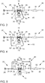
- FIG 3 Another exemplary embodiment of an internal combustion engine 10 with an intake tract 20 and an exhaust system 40 is shown.
- the exhaust gas recirculation 60 is designed as a high-pressure exhaust gas recirculation and branches off from the exhaust gas duct 46 downstream of the outlet 42 of the internal combustion engine 10 and upstream of the turbine 48 of the exhaust gas turbocharger 36 and opens into the intake duct downstream of the compressor 28 and upstream of the inlet 22 24th
- FIG 4 Another exemplary embodiment of an internal combustion engine 10 with an intake tract 20 and an exhaust system 40 is shown.
- the exhaust gas recirculation 60 branches off from the exhaust gas duct 46 downstream of the outlet 42 of the internal combustion engine 10 and upstream of the turbine 48 of the exhaust gas turbocharger 36 and opens into the intake duct 24 downstream of the air filter 26 and upstream of the compressor 28.
- FIG 5 Another exemplary embodiment of an internal combustion engine 10 with an intake tract 20 and an exhaust system 40 is shown.
- the exhaust gas recirculation 60 branches off from the exhaust gas duct 46 downstream of the turbine 48 and upstream of the three-way catalytic converter 50 and opens into the intake duct 24 downstream of the air filter 26 and upstream of the compressor 28.
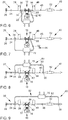
- Figure 6 shows a further embodiment of an internal combustion engine 10.
- a four-way catalytic converter 52 is arranged in the exhaust duct 46 instead of a three-way catalytic converter 50.
- Figure 7 shows a further embodiment of an internal combustion engine 10.
- the three-way catalytic converter 50 in the exhaust gas duct 46 is replaced by a four-way catalytic converter 52.
- Figure 8 shows a further embodiment of an internal combustion engine 10. With essentially the same structure as for Figure 5 the three-way catalytic converter 50 in the exhaust gas duct 46 is replaced by a four-way catalytic converter 52.
- Figure 9 shows a further embodiment of an internal combustion engine 10 with an intake tract 20 and an exhaust system 40.
- a four-way catalytic converter 52 is arranged in the exhaust gas duct 46 downstream of the turbine 48.
- Figure 10 shows a further exemplary embodiment for an internal combustion engine 10 with an intake tract 20 and an exhaust system 40
- Internal combustion engine 10 shown unchanged structure is arranged in the exhaust system 40 downstream of the three-way catalytic converter 50, a gasoline particulate filter 54, the exhaust gas recirculation 60 branches off downstream of the gasoline particle filter 54 from the exhaust gas duct 46.
- This arrangement has the advantage that the exhaust gas of the internal combustion engine 10 is additionally freed of solids, so that the risk of damage from particles which get back into the intake tract 20 via the exhaust gas recirculation 60 is significantly reduced.
- FIG. 11 An alternative embodiment of an internal combustion engine 10 is shown.
- the positions of the gasoline particulate filter 54 and the three-way catalytic converter 50 are interchanged in an otherwise unchanged structure.
- FIG 12 A further exemplary embodiment of an internal combustion engine 10 is shown, in the exhaust gas system 40 of which a gasoline particle filter 54 and downstream of the turbine 48 of the exhaust gas turbocharger 36 and a three-way catalytic converter 50 are arranged.
- the branch 58 on the exhaust gas duct 46, at which the exhaust gas recirculation line 62 of the exhaust gas recirculation 60 branches off from the exhaust gas duct, is provided downstream of the gasoline particle filter 54 and upstream of the three-way catalytic converter 50.
- This arrangement also has the Advantage that the exhaust gas of the internal combustion engine 10 is additionally freed of solids before it reaches the exhaust gas recirculation 60, so that the risk of damage from particles which get back into the intake tract 20 via the exhaust gas recirculation 60 is significantly reduced.
- Figure 13 shows a further embodiment of an internal combustion engine 10.
- the exhaust gas recirculation 60 branches off downstream of the three-way catalytic converter 50 and upstream of the gasoline particle filter 54 from the exhaust gas duct 46.
- the branch 58 at which the exhaust gas recirculation line 62 branches off from the exhaust gas duct 46, is formed downstream of the turbine 48 and upstream of the three-way catalytic converter 50 and the gasoline particle filter 54.
- Figure 15 shows an internal combustion engine 10 with an exhaust system 40, which is essentially the embodiment Figure 14 corresponds.
- the gasoline particle filter 54 is arranged upstream of the three-way catalytic converter 50 in the flow direction of the exhaust gas through the exhaust gas duct 46.
- FIG 16 A further alternative exemplary embodiment for an internal combustion engine 10 with an intake tract 20 and an exhaust system 40 is shown. With essentially the same structure as for Figure 3 In this exemplary embodiment, an additional gasoline particulate filter 54 is arranged downstream of the turbine 48 of the exhaust gas turbocharger 36 and upstream of the three-way catalytic converter 50.
- FIG 17 Another embodiment of an internal combustion engine 10 with a high-pressure exhaust gas recirculation is shown. Compared to the embodiment in Figure 16 only the positions of the three-way catalytic converter 50 and the gasoline particle filter 54 are interchanged, so that the three-way catalytic converter 50 is traversed downstream of the turbine 48 as the first component of the exhaust gas aftertreatment.
- FIG 20 Another exemplary embodiment of an internal combustion engine 10 with an intake tract 20 and an exhaust system 40 is shown.
- the exhaust gas recirculation line 62 branches off downstream of the turbine 48 and upstream of the three-way catalytic converter 50 from the exhaust gas duct 46.
- the exhaust gas recirculation 60 additionally has an exhaust gas recirculation catalytic converter 68 and / or an exhaust gas recirculation filter 66 with which the exhaust gas stream recirculated via the exhaust gas recirculation 60 is additionally cleaned.
- This embodiment offers the advantage that the recirculated exhaust gas can be freed of pollutants and particles.
- the knock tendency of the fuel-air mixture in the combustion chambers can be reduced, since the fuel-air mixture is rendered inert by the recirculated exhaust gas. Furthermore, the raw emissions of the internal combustion engine 10 can be reduced if emission-producing exhaust gas components are converted by the exhaust gas recirculation catalytic converter 68 into inert exhaust gas components and thus inhibit the formation of harmful exhaust gas components.
- a disadvantage of this embodiment is that an additional component in the exhaust gas recirculation 60 in the form of an exhaust gas recirculation filter 66 or an exhaust gas recirculation catalytic converter 68 is required.
- FIG. 21 An embodiment of an internal combustion engine 10 is shown, which essentially corresponds to the embodiment in FIG Figure 13 corresponds, wherein an exhaust gas recirculation catalytic converter 68 and / or an exhaust gas recirculation filter 66 is / are additionally arranged in the exhaust gas recirculation 60.
- the embodiment in Figure 22 essentially corresponds to the exemplary embodiment Figure 12 , the embodiment in Figure 23 the embodiment in Figure 14 and the embodiment in Figure 24 the embodiment in Figure 15 , wherein an exhaust gas recirculation catalytic converter 68 and / or an exhaust gas recirculation filter 66 is / are arranged in each case in the exhaust gas recirculation 60.
- FIG 25 An embodiment of an internal combustion engine 10 with an intake tract 20 and an exhaust system is shown, which essentially corresponds to the embodiment Figure 20 corresponds. Deviating from the embodiment in Figure 20 In this exemplary embodiment, a four-way catalytic converter 52 is provided in the exhaust system 40 instead of the three-way catalytic converter 50.
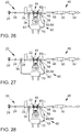
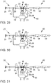
- FIGS. 26 to 31 show further embodiments of an internal combustion engine 10 with an intake tract 20 and an exhaust system 40 with an exhaust gas recirculation 60, an exhaust gas recirculation catalytic converter 68 and / or an exhaust gas recirculation filter 66 being arranged in the exhaust gas recirculation.
Landscapes
- Engineering & Computer Science (AREA)
- Chemical & Material Sciences (AREA)
- Combustion & Propulsion (AREA)
- Mechanical Engineering (AREA)
- General Engineering & Computer Science (AREA)
- Chemical Kinetics & Catalysis (AREA)
- Materials Engineering (AREA)
- Health & Medical Sciences (AREA)
- Toxicology (AREA)
- Exhaust-Gas Circulating Devices (AREA)
- Exhaust Gas After Treatment (AREA)
Abstract
- Betreiben des Verbrennungsmotors (10) mit einem stöchiometrischen Verbrennungsluftgemisch (λ = 1), wobei das Abgas des Verbrennungsmotors (10) durch die mindestens eine Abgasnachbehandlungskomponente (50, 52,54) gereinigt wird,
- Ermitteln eines Betriebspunktes des Verbrennungsmotors (10), wobei eine Abgasrückführungsrate bei konstantem Lastpunkt des Verbrennungsmotors (10) angepasst wird, um die Abgastemperatur (TEG) zu verändern.
Description
- Die Erfindung betrifft ein Verfahren zur Abgasnachbehandlung eines Verbrennungsmotors, sowie ein Abgasnachbehandlungssystem zur Durchführung eines solchen Verfahrens gemäß dem Oberbegriff der unabhängigen Patentansprüche.
- Die aktuelle und eine zukünftig immer schärfer werdende Abgasgesetzgebung stellen hohe Anforderungen an die motorischen Rohemissionen und die Abgasnachbehandlung von Verbrennungsmotoren. Dabei ist es zur Einhaltung der zukünftigen Emissionsgrenzwerte (zum Beispiel EU7, US SULEV20) notwendig, einen Ottomotor durchgängig mit einem stöchiometrischen Verbrennungsluftgemisch zu betreiben, um eine funktionssichere Abgasnachbehandlung bei allen Betriebspunkten des Verbrennungsmotors zu gewährleisten. Bei modernen Verbrennungsmotoren, welche durch "Downsizing" eine sehr hohe spezifische Leistungsdichte aufweisen, kann bei hohen abgerufenen Motorleistungen die Abgastemperatur sehr stark ansteigen. Wird bei einem solchen Lastpunkt der Verbrennungsmotor mit einem stöchiometrischen Verbrennungsluftverhältnis betrieben, ergibt sich ein hoher Wärmeeintrag in die Abgasnachbehandlungskomponenten, welcher durch exotherme katalytische Reaktionen an den Abgasnachbehandlungskomponenten noch verstärkt werden kann. Dabei können Betriebstemperaturen der Abgasnachbehandlungskomponenten auftreten, welche oberhalb der dauerhaft zulässigen Materialgrenztemperatur liegen und schlussendlich zu einer thermischen Schädigung der Abgasnachbehandlungskomponenten bis hin zum Ausfall dieser Abgasnachbehandlungskomponenten führen können.
- Aus dem Stand der Technik sind verschiedene Maßnahmen bekannt, um bei einem Volllastbetrieb des Verbrennungsmotors die Abgastemperatur zu senken. Eine erste Maßnahme zur Absenkung der Abgastemperatur ist eine Anreicherung des Verbrennungsluftgemischs im Volllastbetrieb. Dabei wird das Verbrennungsluftverhältnis in Richtung eines unterstöchiometrischen Verbrennungsluftverhältnisses verschoben. Somit ist nicht mehr genug Sauerstoff in den Brennräumen vorhanden, um den Kraftstoff vollständig zu verbrennen, was zu einer Kühlung der Verbrennung und des Abgases durch den unverbrannten Kraftstoff führt. Gleichzeitig steigen jedoch auch die Abgasemissionen, insbesondere die Emissionen an unverbrannten Kohlenwasserstoffen und Kohlenmonoxid sowie der Kraftstoffverbrauch.
- Als weitere Maßnahme ist die Verwendung eines Abgaskühlers bekannt. Dabei wird die Kühlleistung so gewählt, dass die Abgastemperatur stromaufwärts des Einlasses der Abgasnachbehandlungskomponente derart gesenkt wird, dass eine thermische Schädigung der Abgasnachbehandlungskomponente vermieden wird. Dabei ist der zusätzliche Wärmeeintrag in die Abgasnachbehandlungskomponente durch eine exotherme Reaktion an der Abgasnachbehandlungskomponente zu berücksichtigen. Bei Verbrennungsmotoren mit hoher spezifischer Motorleistung sind jedoch hohe Kühlleistungen notwendig, um eine hinreichende Kühlung des Abgasstroms unter allen Betriebsbedingungen sicherzustellen. Dies führt zu großen Abgaskühlern, welchen einen hohen Bauraumbedarf aufweisen und das Gewicht eines Kraftfahrzeuges erhöhen. Daher werden solche Abgaskühler nur so groß ausgeführt, dass sie gerade die Funktion zum Bauteilschutz der Abgasnachbehandlungskomponenten erfüllen. Eine weitere Absenkung der Abgastemperatur im Rahmen eines Abgastemperaturmanagements kann daher nicht erfolgen. Darüber hinaus werden bei sehr hohen spezifischen Motorleistungen die Auslassventile sehr heiß und können mit dieser Maßnahme nicht abgekühlt werden, sodass ein stöchiometrischer Betrieb bei Volllast zu einer thermischen Schädigung der Auslassventile führen könnte.
- Als weitere Maßnahme zur Reduzierung der Verbrennungstemperatur und der Abgastemperatur ist es bekannt, Wasser in die Brennräume des Verbrennungsmotors einzuspritzen. Obwohl eine solche Wassereinspritzung sehr wirkungsvoll ist, stehen den Vorteilen einige Nachteile gegenüber. Zum einen ist ein zusätzlicher Injektor zum Einbringen des Wassers notwendig. Ferner ist der Wasserverbrauch bei einem Lastprofil mit hohem Volllastanteil entsprechend hoch, was dazu führen kann, dass der Fahrer das Wasser ähnlich dem Kraftstoff bei jedem Tankstopp nachfüllen muss. Um eine Beschädigung des Verbrennungsmotors zu vermeiden, wird ein entmineralisiertes Wasser verwendet, was die Kosten für die Wassereinspritzung zusätzlich erhöht. Zudem sind Heizmaßnahmen für den Wassertank vorzusehen, um im Winter ein Einfrieren des Wassers zu vermeiden.
- Aus der
DE 10 2005 045 294 A1 ist ein Verfahren zur Abgasnachbehandlung eines Dieselmotors bekannt, bei welchem über eine Abgasrückführung Abgas zurück in den Ansaugtrakt geführt wird, um die Rohemissionen bei einer überstöchiometrischen Verbrennung, insbesondere die Stickoxid-Emissionen des Verbrennungsmotors zu reduzieren. Dabei wird das zurückgeführte Abgas durch einen Abgasrückführungskühler abgekühlt, um die Temperatur in den Brennräumen zu reduzieren und somit die Bildung von Stickoxiden zu verringern. - Aus der
DE 10 2016 006 327 A1 sind eine Vorrichtung und ein Verfahren zur Anpassung eines Abgasrückführungsventils bekannt, um den Ladungswechsel zu optimieren und um die Verbrennungstemperatur herabzusetzen und somit der Erzeugung von Stickoxiden entgegenzuwirken. Dabei ist das Kraftfahrzeug vorzugsweise als Hybridfahrzeug ausgeführt und weist sowohl einen Verbrennungsmotor als auch einen Elektromotor auf, wobei die Lastanforderung an den Verbrennungsmotor durch ein Variieren der Leistung des Elektromotors angepasst wird. - Aus der
DE 10 2016 111 366 A1 sind ein Verfahren und ein System zur Verbesserung eines Betriebs eines Verbrennungsmotors bei höheren Drehzahlen und Lasten bekannt. Dabei kann Kraftstoff in die Abgasanlage des Verbrennungsmotors eingespritzt werden, um die thermische Belastung der Abgasnachbehandlungskomponenten zu reduzieren, wenn der Verbrennungsmotor bei höheren Drehzahlen und hoher Last betrieben wird. - Der Erfindung liegt nun die Aufgabe zugrunde, einen Verbrennungsmotor in allen Betriebspunkten mit einem stöchiometrischen Verbrennungsluftverhältnis betreiben zu können, um eine effiziente Abgasnachbehandlung zu ermöglichen und die aus dem Stand der Technik bekannten Nachteile zu überwinden.
- Erfindungsgemäß wird diese Aufgabe durch ein Verfahren zur Abgasnachbehandlung eines Verbrennungsmotors mit mindestens einem Brennraum, dessen Einlass mit einem Ansaugtrakt und dessen Auslass mit einer Abgasanlage des Verbrennungsmotors verbunden ist, gelöst. Dabei ist an jedem Brennraum mindestens eine Zündquelle (zum Beispiel Zündkerze) angeordnet, um ein stöchiometrisches Verbrennungsluftgemisch in dem Brennraum zu zünden. Die Abgasanlage weist einen Abgaskanal auf, in welchem mindestens eine Abgasnachbehandlungskomponente, insbesondere ein Drei-Wege-Katalysator, ein Ottopartikelfilter oder ein Vier-Wege-Katalysator angeordnet ist. Die Abgasanlage ist über eine Abgasrückführung mit dem Ansaugtrakt des Verbrennungsmotors verbunden, wobei in der Abgasrückführung ein Abgasrückführungskühler angeordnet ist. Das erfindungsgemäße Verfahren umfasst folgende Schritte:
- Betreiben des Verbrennungsmotors mit einem stöchiometrischen Verbrennungsluftgemisch (λ = 1), wobei das Abgas des Verbrennungsmotors durch die Abgasnachbehandlungskomponente gereinigt wird,
- Ermitteln eines Betriebspunktes des Verbrennungsmotors, wobei eine Abgasrückführungsrate bei konstantem Lastpunkt des Verbrennungsmotors angepasst wird, um die Abgastemperatur zu verändern.
- Die Voraussetzung zur Durchführung eines solchen Verfahrens ist das Vorhandensein einer Abgasrückführung. Mit dieser Abgasrückführung lassen sich in definierten Grenzen, insbesondere im Bereich von 0 % bis 25 % Massenanteil des Abgases, beliebige Abgasrückführungsraten einstellen. In Kombination mit einer geeigneten Motorsteuerstrategie wird der jeweilige Lastpunkt des Verbrennungsmotors konstant gehalten und die Abgastemperatur über eine Veränderung der Abgasrückführungsrate angepasst. Dadurch ist es möglich, den Verbrennungsmotor auch bei hoher Last und/oder hoher Drehzahl mit hoher spezifischer Leistung und einem stöchiometrischen Verbrennungsluftverhältnis zu betreiben, ohne die Auslassventile des Verbrennungsmotors und/oder die Abgasnachbehandlungskomponenten thermisch zu schädigen.
- Durch die in den abhängigen Ansprüchen aufgeführten zusätzlichen Merkmale sind Verbesserungen und nicht triviale Weiterentwicklungen des im unabhängigen Anspruch angegebenen Verfahrens zur Abgasnachbehandlung eines Verbrennungsmotors möglich.
- In einer bevorzugten Ausführungsform des Verfahrens ist vorgesehen, dass zusätzlich der Zündzeitpunkt der Zündeinrichtung bei konstantem Lastpunkt des Verbrennungsmotors verschoben wird, um die Abgastemperatur anzupassen. Neben der Abgasrückführung kann die Abgastemperatur auch durch andere motorische Parameter beeinflusst werden. So führt beispielsweise eine Spätverstellung des Zündzeitpunktes in den Brennräumen bei konstant gehaltenem Lastpunkt zu einer Erhöhung der Abgastemperatur bei einer gleichzeitigen Erhöhung des Abgasmassenstroms, da der thermische Wirkungsgrad des Verbrennungsmotors bei einer Verstellung des Zündzeitpunktes in Richtung "spät" abnimmt. Kombiniert man verfahrenstechnisch die Effekte der Abgasrückführung mit denen einer Zündwinkelverstellung, so kann bei gleichbleibendem Lastpunkt und gleichbleibenden Abgastemperaturen der Abgasmassenstrom verändert werden.
- Alternativ oder zusätzlich ist vorgesehen, dass die Abgasrückführungsmenge bei konstantem Lastpunkt des Verbrennungsmotors erhöht wird, um die Abgastemperatur zu senken. Für einen beispielhaften Arbeitspunkt des Verbrennungsmotors lassen sich auf diese Art die Abgastemperatur sowohl stromaufwärts des Katalysators als auch stromabwärts des Katalysators um bis zu 120°C reduzieren. Darüber hinaus kann eine erhöhte Abgasrückführungsrate dazu genutzt werden, die durch die exotherme Reaktion auf der Oberfläche des Katalysators freigesetzte Wärme zu reduzieren. Dieser Effekt ist auch an anderen Lastpunkten des Verbrennungsmotors darstellbar. Dabei können die Leistung und das abgegebene Drehmoment des Verbrennungsmotors konstant gehalten werden, sodass diese Maßnahme für den Fahrer eines Kraftfahrzeuges nicht spürbar ist und somit weder zu Einbußen beim Komfort noch bei den Fahrleistungen des Kraftfahrzeuges führt.
- In einer weiteren Verbesserung des Verfahrens ist vorgesehen, dass eine Brennraumtemperatur und/oder eine Abgastemperatur ermittelt wird, wobei die Abgasrückführungsrate der Abgasrückführung erhöht wird, wenn die Brennraumtemperatur oder die Abgastemperatur jeweils einen definierten Schwellenwert übersteigt. Somit lassen sich mithilfe einer über die Abgastemperatur oder die Brennraumtemperatur gesteuerten oder geregelten Abgasrückführung Abgastemperaturen einstellen, welche funktionssicher die maximal zulässige Bauteiltemperatur der Abgasnachbehandlungskomponenten nicht überschreiten. Darüber hinaus ist es möglich, ein aktives Temperaturmanagement derart zu gestalten, dass unterschiedliche Abgasmassenströme bei gleichgehaltenen Lastpunkten und gleichgehaltenen Abgastemperaturen eingestellt werden können.
- In einer bevorzugten Ausführungsvariante des Verfahrens ist vorgesehen, dass eine Abgastemperatur des Verbrennungsmotors konstant gehalten wird, indem die Abgasrückführungsrate und/oder der Zündzeitpunkt des Verbrennungsgemischs in den Brennräumen angepasst werden. Durch eine konstante Abgastemperatur können beispielsweise die Katalysatoren an einem maximaleffizienten Betriebspunkt betrieben werden, sodass eine besonders effiziente Konvertierung der im Abgasstrom des Verbrennungsmotors vorhandenen Schadstoffe möglich ist. Alternativ kann eine konstante Abgastemperatur notwendig sein, um einen Ottopartikelfilter oder einen Vier-Wege-Katalysator zu regenerieren. Dabei kann eine Temperatur eingestellt werden, welche oberhalb oder unterhalb derjenigen Temperatur liegt, welche sich bei einem maximal effizienten oder emissionsoptimalen Betriebspunkt des Verbrennungsmotors einstellen würde.
- In einer bevorzugten Ausführungsform des Verfahrens ist vorgesehen, dass die Abgasrückführungsrate über ein Abgasrückführungsventil in der Abgasrückführung gesteuert oder regelt wird. Ein Abgasrückführungsventil ist eine einfache und vergleichsweise kostengünstige Möglichkeit, den Abgasrückführmassenstrom des Verbrennungsmotors einzustellen. Zudem kann durch das Abgasrückführungsventil verhindert werden, dass Frischluft über die Abgasrückführung unkontrolliert in den Abgaskanal gefördert wird und somit die Abgasnachbehandlung negativ beeinflusst.
- Erfindungsgemäß wird ein Abgasnachbehandlungssystem für einen Verbrennungsmotor mit mindestens einem Brennraum, dessen Einlass mit einem Ansaugtrakt und dessen Auslass mit einer Abgasanlage des Verbrennungsmotors verbunden sind, vorgeschlagen, wobei an jedem Brennraum mindestens eine Zündeinrichtung angeordnet ist, um ein stöchiometrisches Verbrennungsluftgemisch in dem Brennraum zu zünden. Dabei weist die Abgasanlage einen Abgaskanal auf, in welchem mindestens eine Abgasnachbehandlungskomponente, insbesondere ein Drei-Wege-Katalysator, ein Ottopartikelfilter oder ein Vier-Wege-Katalysator, angeordnet ist. Die Abgasanlage ist über eine Abgasrückführung mit dem Ansaugtrakt des Verbrennungsmotors verbunden, wobei in der Abgasrückführung ein Abgasrückführungskühler angeordnet ist. Dem Verbrennungsmotor ist ein Motorsteuergerät zugeordnet, mit welchem ein erfindungsgemäßes Verfahren ausgeführt wird, wenn ein maschinenlesbarer Programmcode durch das Motorsteuergerät ausgeführt wird. Durch ein erfindungsgemäßes Abgasnachbehandlungssystem können die Abgastemperaturen bei einem Ottomotor eingestellt und insbesondere reduziert werden, sodass im gesamten Betriebsbereich ohne zusätzliche Kühlmaßnahmen ein stöchiometrischer Betrieb des Verbrennungsmotors möglich ist. Dies ermöglicht an sämtlichen Betriebspunkten des Verbrennungsmotors eine optimale Abgasnachbehandlung und somit minimale Emissionen.
- In einer bevorzugten Ausführungsform des Abgasnachbehandlungssystems ist vorgesehen, dass in der Abgasrückführung ein Abgasrückführungsfilter und/oder ein Abgasrückführungskatalysator angeordnet ist. Durch einen Abgasrückführungsfilter kann verhindert werden, dass Rußpartikel oder sonstige Partikel über die Abgasrückführung in den Ansaugtrakt gelangen und dort den Verdichter des Abgasturboladers beschädigen. Durch einen Abgasrückführungskatalysator kann verhindert werden, dass neben den gewünschten Abgaskomponenten, insbesondere Kohlenstoffdioxid, auch weitere Abgaskomponenten in den Ansaugtrakt gelangen, welche die Rohemissionen des Verbrennungsmotors erhöhen würden. Zudem kann die Klopfneigung bei der Verbrennung des Kraftstoffluftgemischs in den Brennräumen des Verbrennungsmotors reduziert werden, wobei das Kraftstoffluftgemisch durch die Abgasrückführung eine Inertisierung erfährt und dadurch die Neigung zur Selbstentzündung verringert wird. Somit können die Emissionen des Verbrennungsmotors insbesondere dann nochmals verringert werden, wenn die Abgasrückführung stromaufwärts des Drei-Wege-Katalysators oder des Vier-Wege-Katalysators aus dem Abgaskanal abzweigt.
- In einer vorteilhaften Ausführungsform der Erfindung ist vorgesehen, dass der Abgasrückführungskühler als Wärmetauscher, insbesondere als Kreuzstrom- oder Gegenstromwärmetauscher, ausgeführt ist, welcher mit dem Kühlmittelkreislauf des Verbrennungsmotors verbunden ist und von dem Kühlmittel des Verbrennungsmotors durchströmt wird. Durch das Kühlmittel des Verbrennungsmotors ist eine hocheffiziente Kühlung des Abgasstroms möglich. Zudem ist kein zusätzlicher Kühlmittelkreislauf notwendig, welcher zusätzliche Leistung erfordern würde und somit den Wirkungsgrad des Verbrennungsmotors reduzieren würde.
- In einer vorteilhaften Ausführungsform des Abgasnachbehandlungssystems ist vorgesehen, dass in der Abgasanlage mindestens ein Abgassensor angeordnet ist. Durch einen Abgassensor kann die Abgaszusammensetzung oder die Konzentration zumindest eines im Abgasstrom des Verbrennungsmotors vorhandenen Schadstoffs ermittelt werden. Dabei kann insbesondere die Konzentration von Stickoxiden, Kohlenwasserstoffen oder Kohlenmonoxid im Abgas ermittelt werden. Die Ergebnisse des Abgassensors werden an das Motorsteuergerät des Verbrennungsmotors übertragen und können dort genutzt werden, um die Abgasnachbehandlung zu optimieren.
- In einer vorteilhaften Ausführungsform der Erfindung ist vorgesehen, dass die Abgasrückführung als eine Niederdruck-Abgasrückführung ausgebildet ist, wobei die Abgasrückführungsleitung stromabwärts einer Turbine eines Abgasturboladers aus dem Abgaskanal abzweigt und stromaufwärts eines Verdichters des Abgasturboladers in den Ansaugkanal einmündet. Durch eine Niederdruck-Abgasrückführung kann vergleichsweise kaltes Abgas, welches sich beim Durchströmen der Turbine des Abgasturboladers bereits abgekühlt hat, zurückgeführt werden, wodurch eine besonders effiziente Herabsetzung der Verbrennungstemperatur möglich ist.
- Besonders bevorzugt ist dabei, wenn die Abgasrückführung stromabwärts eines Ottopartikelfilters oder eines Vier-Wege-Katalysators aus dem Abgaskanal abzweigt. Zweigt die Abgasrückführung stromabwärts des Ottopartikelfilters oder des Vier-Wege-Katalysators aus dem Abgaskanal ab, kann auf einen Abgasrückführungsfilter verzichtet werden, da die Feststoffe aus dem Abgasstrom bereits durch den Ottopartikelfilter oder den Vier-Wege-Katalysator herausgefiltert wurden. Dadurch kann die Abgasrückführung vereinfacht und somit kostengünstiger ausgeführt werden.
- Alternativ ist mit Vorteil vorgesehen, dass die Abgasrückführung als Hochdruck-Abgasrückführung ausgebildet ist, wobei die Abgasrückführungsleitung stromabwärts eines Auslasses des Verbrennungsmotors und stromaufwärts einer Turbine eines Abgasturboladers aus dem Abgaskanal abzweigt und stromabwärts eines Verdichters des Abgasturboladers in den Ansaugkanal einmündet. Eine Hochdruck-Abgasrückführung kann besonders kompakt und mit kurzen Abgasrückführungsleitungen ausgeführt werden. Dadurch kann eine solche Hochdruckabgasrückführung mit geringem Bauraumbedarf umgesetzt werden und ebenfalls effizient dazu beitragen, sowohl die Temperatur in den Brennräumen des Verbrennungsmotors als auch die Abgastemperatur des Verbrennungsmotors herabzusetzen.
- Alternativ kann die Abgasrückführung auch stromabwärts eines Auslasses des Verbrennungsmotors und stromaufwärts einer Turbine eines Abgasturboladers aus dem Abgaskanal abzweigen und stromaufwärts eines Verdichters des Abgasturboladers in den Ansaugkanal einmünden.
- In einer weiteren Verbesserung des Abgasnachbehandlungssystem ist vorgesehen, dass im Abgaskanal stromaufwärts eines Drei-Wege-Katalysators oder stromaufwärts eines Vier-Wege-Katalysators eine Lambdasonde, insbesondere eine Breitband-Lambda-Sonde angeordnet ist, mit welcher ein stöchiometrisches Verbrennungsluftverhältnis des Verbrennungsmotors eingeregelt wird. Durch eine Lambdasonde, welche vorzugsweise stromabwärts der Turbine des Abgasturboladers und stromaufwärts des Drei-Wege-Katalysators oder Vier-Wege-Katalysators angeordnet ist, ist eine besonders einfache und genaue Regelung des Verbrennungsluftverhältnisses des Verbrennungsmotors möglich. Dadurch kann das Verbrennungsluftverhältnis auf ein im Mittel stöchiometrisches Verbrennungsluftverhältnis eingeregelt werden, sodass eine maximaleffiziente Abgasnachbehandlung des Abgasstroms durch die Abgasnachbehandlungskomponenten möglich ist.
- Die verschiedenen in dieser Anmeldung genannten Ausführungsformen der Erfindung sind, sofern im Einzelfall nicht anders ausgeführt, mit Vorteil miteinander kombinierbar.
- Die Erfindung wird nachfolgend in Ausführungsbeispielen anhand der zugehörigen Zeichnungen erläutert. Gleiche Bauteile oder Bauteile mit gleicher Funktion sind dabei in den verschiedenen Figuren mit gleichen Bezugszeichen gekennzeichnet. Es zeigen:
- Figur 1
- ein bevorzugtes Ausführungsbeispiel eines schematisch dargestellten Verbrennungsmotors mit einem Ansaugtrakt und einer Abgasanlage zur Durchführung eines erfindungsgemäßen Verfahrens zur Abgasnachbehandlung;
- Figur 2
- Diagramme mit den Temperaturverläufen stromabwärts der Turbine des Abgasturboladers und stromabwärts des Katalysators sowie die Temperaturänderung über den Katalysator bei Durchführung eines erfindungsgemäßen Verfahrens zur Abgasnachbehandlung, zweites Ausführungsbeispiel eines Verbrennungsmotors mit einer erfindungsgemäßen Vorrichtung zur Abgasnachbehandlung;
- Figuren 3 - 5
- weitere Ausführungsbeispiele für Verbrennungsmotoren, in deren Abgasanlagen jeweils ein Drei-Wege-Katalysator angeordnet ist, und welche eine Abgasrückführung zur Durchführung eines erfindungsgemäßen Verfahrens zur Abgasnachbehandlung aufweisen;
- Figuren 6 - 9
- Ausführungsbeispiele für Verbrennungsmotoren, in deren Abgasanlagen jeweils ein Vier-Wege-Katalysator angeordnet ist, und welche eine Abgasrückführung zur Durchführung eines erfindungsgemäßen Verfahrens zur Abgasnachbehandlung aufweisen;
- Figuren 10 - 19
- Ausführungsbeispiele für Verbrennungsmotoren, in deren Abgasanlagen jeweils ein Drei-Wege-Katalysator und ein Ottopartikelfilter angeordnet sind, und welche eine Abgasrückführung zur Durchführung eines erfindungsgemäßen Verfahrens zur Abgasnachbehandlung aufweisen; und
- Figuren 20 - 31
- Ausführungsbeispiele für Verbrennungsmotoren, in deren Abgasanlagen jeweils ein Drei-Wege-Katalysator, ein Drei-Wege-Katalysator und ein Ottopartikelfilter oder ein Vier-Wege-Katalysator angeordnet sind, und bei denen jeweils in der Abgasrückführung zusätzlich ein weiterer Katalysator und/oder Filter angeordnet ist.
-
Figur 1 zeigt die schematische Darstellung eines Verbrennungsmotors 10 mit einem Ansaugtrakt 20 und einer Abgasanlage 40. Der Verbrennungsmotor 10 ist als ein direkteinspritzender Ottomotor ausgeführt und weist mehrere Brennräume 12 auf. An den Brennräumen 12 ist jeweils ein Kraftstoffinjektor 16 zur Einspritzung eines Kraftstoffs in den jeweiligen Brennraum 12 und jeweils eine Zündkerze 14 zur Zündung eines Kraftstoff-Luft-Gemischs angeordnet. Der Brennraum 12 wird durch einen Kolben 18 begrenzt, welcher in einer Zylinderbohrung des Verbrennungsmotors 10 linear verschiebbar angeordnet ist. Der Kolben 18 ist über einen Pleuel mit einer Kurbelwelle des Verbrennungsmotors 10 verbunden, welche die Leistung des Verbrennungsmotors 10 auf eine mit einem Getriebe verbindbare Abtriebswelle überträgt. Der Verbrennungsmotor 10 ist mit seinem Einlass 22 mit einem Luftversorgungssystem 20 und mit seinem Auslass 42 mit einer Abgasanlage 40 verbunden. An den Brennräumen 12 sind Einlassventile 38 und Auslassventile 44 angeordnet, mit welchen eine fluidische Verbindung vom Ansaugtrakt 20 zu den Brennräumen 12 oder von den Brennräumen 12 zur Abgasanlage 40 geöffnet oder verschlossen werden kann. - Das Luftversorgungssystem 20 umfasst einen Ansaugkanal 24, in welchem in Strömungsrichtung von Frischluft durch den Ansaugkanal 24 ein Luftfilter 26, stromabwärts des Luftfilters 26 ein Verdichter 28 eines Abgasturboladers 36, stromabwärts des Verdichters 28 eine Drosselklappe 30 und weiter stromabwärts ein Ladeluftkühler 32 angeordnet sind. Zusätzlich kann im Ansaugtrakt 20 ein Luftmassenmesser angeordnet sein, um die den Brennräumen 12 des Verbrennungsmotors zugeführte Luftmenge zu bestimmen. Dabei kann der Luftmassenmesser auch in einem Filtergehäuse des Luftfilters 26 integriert sein, sodass der Luftfilter 26 und der Luftmassenmesser eine Baugruppe ausbilden. Stromabwärts des Luftfilters 26 und stromaufwärts des Verdichters 28 ist eine Einmündung 34 vorgesehen, an welcher eine Abgasrückführungsleitung 62 einer Abgasrückführung 60 in den Ansaugkanal 24 mündet. Alternativ zu einem Kraftstoffinjektor 16, welcher den Kraftstoff in die Brennräume 12 des Verbrennungsmotors 10 einspritzt, kann auch eine Einspritzung von Kraftstoff in den Ansaugtrakt 20 erfolgen.
- Die Abgasanlage 40 umfasst einen Abgaskanal 46, in welchem in Strömungsrichtung eines Abgases des Verbrennungsmotors 10 durch den Abgaskanal 46 eine Turbine 48 des Abgasturboladers 36 angeordnet ist, welche den Verdichter 28 im Ansaugtrakt 20 über eine Welle antreibt. Der Abgasturbolader 36 kann als Abgasturbolader 36 mit variabler Turbinengeometrie ausgeführt sein. Dazu sind einem Turbinenrad der Turbine 48 verstellbare Leitschaufeln vorgeschaltet, über welche die Anströmung des Abgases auf die Schaufeln der Turbine 48 variiert werden kann. Stromabwärts der Turbine 48 ist mindestens eine Abgasnachbehandlungskomponente 50, 52, 54 im Abgaskanal 46 des Verbrennungsmotors 10 angeordnet. Dabei ist in dem in
Figur 1 dargestellten Ausführungsbeispiel unmittelbar stromabwärts der Turbine 48 des Abgasturboladers 36 als erste Komponente der Abgasnachbehandlung ein Drei-Wege-Katalysator 50 angeordnet. Stromabwärts des Drei-Wege-Katalysators 50 zweigt an einer Verzweigung 58 eine Abgasrückführung 60 aus dem Abgaskanal 46 ab und verbindet den Abgaskanal 46 mit dem Ansaugkanal 24 stromabwärts des Luftfilters 26 und stromaufwärts des Verdichters 28 des Abgasturboladers 36. Stromabwärts der Verzweigung 58 kann eine Abgasklappe vorgesehen sein, um die Abgasrückführungsrate durch die Abgasrückführung 60 zu steuern. - Die Abgasrückführung 60 umfasst neben der Abgasrückführungsleitung 62 einen Abgasrückführungskühler 70 und ein Abgasrückführungsventil 64, über welches die Abgasrückführung durch die Abgasrückführungsleitung 62 steuerbar ist. In dem Abgaskanal 46 kann eine Abgastemperatur durch einen Temperatursensoren 82 erfasst werden oder durch das Motorsteuergerät 80 berechnet werden, um die Abgasrückführung 60 zu aktivieren, sobald die Abgastemperatur TEG einen definierten Schwellenwert überschritten hat. An der Abgasrückführungsleitung 62 der Abgasrückführung 60 kann ein weiterer Temperatursensor 84 vorgesehen werden, um die Temperatur des zurückgeführten Abgases stromabwärts des Abgasrückführungskühlers 70 zu ermitteln. Dadurch kann vermieden werden, dass das zurückgeführte Abgas so stark gekühlt wird, dass der Taupunkt unterschritten wird und es zu einem Auskondensieren von Wassertropfen in der Abgasrückführungsleitung 62 kommt. Somit kann verhindert werden, dass Wasserdampf oder im Abgas enthaltene Gaskomponenten auskondensieren und in der Abgasrückführung 60 oder im Ansaugtrakt 20 zu Beschädigungen oder Ablagerungen führen. Der Abgasrückführungskühler 70 ist vorzugsweise als Kreuzstrom-, Gegenstrom- oder Parallelstrom-Wärmetauscher 72 ausgeführt und ist mit dem Kühlmittelkreislauf des Verbrennungsmotors 10 verbunden. Dazu weist der Abgasrückführungskühler 70 einen Zulauf 74 und einen Ablauf 76 auf, über welche das Kühlmittel in den Abgasrückführungskühler 70 ein- und ausströmt.
- In der Abgasanlage 40 ist stromabwärts der Turbine 48 des Abgasturboladers 36 und stromaufwärts des Drei-Wege-Katalysators 50 eine Lambdasonde 78 angeordnet, um das Verbrennungsluftverhältnis λE des Verbrennungsmotors 10 zu regeln. Dazu ist die Lambdasonde 78 mit einem Motorsteuergerät 80 des Verbrennungsmotors 10 verbunden, über welches u.a. die Einspritzmenge an Kraftstoff in die Brennräume 12 und der Zündzeitpunkt sowie die Stellung der Drosselklappe 30 gesteuert werden. Ferner kann im Abgaskanal 46 ein weiterer Abgassensor 56 und/oder ein Temperatursensor 82 vorgesehen sein.
- Im Fahrbetrieb eines Kraftfahrzeuges wird der Verbrennungsmotor 10 mit einem stöchiometrischen Verbrennungsluftverhältnis betrieben. Steigt die Brennraumtemperatur TCC oder die Abgastemperatur TEG aufgrund einer hohen Leistungsanforderung an den Verbrennungsmotor 10 über einen kritischen Schwellenwert an, so wird aus Gründen des thermischen Bauteilschutzes die Abgasrückführungsrate erhöht, um die Temperatur im Brennraum 12 und in der Abgasanlage 40 zu senken.
- Wie aus
Figur 2a ersichtlich ist, stellt sich jetzt in Abhängigkeit von der gewählten Abgasrückführungsrate eine Abgastemperatur TEGT stromabwärts der Turbine 48 des Abgasturboladers 36 und stromaufwärts des Drei-Wege-Katalysators ein, welche umso niedriger ausfällt, je höher die Abgasrückführungsrate gewählt wurde. Parallel sinkt auch, wie inFigur 2b dargestellt, die Abgastemperatur TEGK stromabwärts des Drei-Wege-Katalysators 50. Wie inAbbildung 2c zu erkennen ist, kann die gewählte Abgasrückführungsrate dazu beitragen, die Exotherme, welche sich im Drei-Wege-Katalysator 50 aus exothermen Nachreaktionen von unverbrannten Kraftstoffkomponenten einstellt, zu reduzieren. - In
Figur 3 ist ein weiteres Ausführungsbeispiel eines Verbrennungsmotors 10 mit einem Ansaugtrakt 20 und einer Abgasanlage 40 dargestellt. Bei im Wesentlichen gleichem Aufbau wie zuFigur 1 ausgeführt, ist die Abgasrückführung 60 in diesem Ausführungsbeispiel als Hochdruck-Abgasrückführung ausgeführt und zweigt stromabwärts des Auslasses 42 des Verbrennungsmotors 10 und stromaufwärts der Turbine 48 des Abgasturboladers 36 aus dem Abgaskanal 46 ab und mündet stromabwärts des Verdichters 28 und stromaufwärts des Einlasses 22 in den Ansaugkanal 24. - In
Figur 4 ist ein weiteres Ausführungsbeispiel eines Verbrennungsmotors 10 mit einem Ansaugtrakt 20 und einer Abgasanlage 40 dargestellt. Bei im Wesentlichen gleichem Aufbau wie zuFigur 1 ausgeführt, zweigt die Abgasrückführung 60 stromabwärts des Auslasses 42 des Verbrennungsmotors 10 und stromaufwärts der Turbine 48 des Abgasturboladers 36 aus dem Abgaskanal 46 ab und mündet stromabwärts des Luftfilters 26 und stromaufwärts des Verdichters 28 in den Ansaugkanal 24. - In
Figur 5 ist ein weiteres Ausführungsbeispiel eines Verbrennungsmotors 10 mit einem Ansaugtrakt 20 und einer Abgasanlage 40 dargestellt. Bei im Wesentlichen gleichem Aufbau wie zuFigur 1 ausgeführt, zweigt die Abgasrückführung 60 in diesem Ausführungsbeispiel stromabwärts der Turbine 48 und stromaufwärts des Drei-Wege-Katalysators 50 aus dem Abgaskanal 46 ab und mündet stromabwärts des Luftfilters 26 und stromaufwärts des Verdichters 28 in den Ansaugkanal 24. -
Figur 6 zeigt ein weiteres Ausführungsbeispiel eines Verbrennungsmotors 10. Bei im Wesentlichen gleichem Aufbau wie zuFigur 3 ausgeführt ist im Abgaskanal 46 anstelle eines Drei-Wege-Katalysators 50 ein Vier-Wege-Katalysator 52 angeordnet. -
Figur 7 zeigt ein weiteres Ausführungsbeispiel eines Verbrennungsmotors 10. Bei im Wesentlichen gleichem Aufbau wie zuFigur 4 ausgeführt ist der Drei-Wege-Katalysator 50 im Abgaskanal 46 durch einen Vier-Wege-Katalysator 52 ersetzt. -
Figur 8 zeigt ein weiteres Ausführungsbeispiel eines Verbrennungsmotors 10. Bei im Wesentlichen gleichem Aufbau wie zuFigur 5 ausgeführt ist der Drei-Wege-Katalysator 50 im Abgaskanal 46 durch einen Vier-Wege-Katalysator 52 ersetzt. -
Figur 9 zeigt ein weiteres Ausführungsbeispiel für einen Verbrennungsmotor 10 mit einem Ansaugtrakt 20 und einer Abgasanlage 40. Bei ansonsten gleichem Aufbau wie zuFigur 1 ausgeführt ist anstelle eines Drei-Wege-Katalysators 50 ein Vier-Wege-Katalysator 52 im Abgaskanal 46 stromabwärts der Turbine 48 angeordnet. -
Figur 10 zeigt ein weiteres Ausführungsbeispiel für einen Verbrennungsmotor 10 mit einem Ansaugtrakt 20 und einer Abgasanlage 40. Bei ansonsten gegenüber dem inFigur 1 dargestellten Verbrennungsmotor 10 unverändertem Aufbau ist in der Abgasanlage 40 stromabwärts des Drei-Wege-Katalysators 50 ein Ottopartikelfilter 54 angeordnet, wobei die Abgasrückführung 60 stromabwärts des Ottopartikelfilters 54 aus dem Abgaskanal 46 abzweigt. Diese Anordnung hat den Vorteil, dass das Abgas des Verbrennungsmotors 10 zusätzlich von Feststoffen befreit wird, sodass die Gefahr von Beschädigungen durch Partikel, welche über die Abgasrückführung 60 zurück in den Ansaugtrakt 20 gelangen, deutlich reduziert ist. - In
Figur 11 ist ein alternatives Ausführungsbeispiel eines Verbrennungsmotors 10 dargestellt. Dabei sind bei ansonsten unverändertem Aufbau die Positionen des Ottopartikelfilters 54 und des Drei-Wege-Katalysators 50 vertauscht. - In
Figur 12 ist ein weiteres Ausführungsbeispiel eines Verbrennungsmotors 10 dargestellt, in dessen Abgasanlage 40 stromabwärts der Turbine 48 des Abgasturboladers 36 ein Ottopartikelfilter 54 und stromabwärts ein Drei-Wege-Katalysator 50 angeordnet sind. Dabei ist die Verzweigung 58 am Abgaskanal 46, an welcher die Abgasrückführungsleitung 62 der Abgasrückführung 60 aus dem Abgaskanal abzweigt, stromabwärts des Ottopartikelfilters 54 und stromaufwärts des Drei-Wege-Katalysators 50 vorgesehen. Auch diese Anordnung hat den Vorteil, dass das Abgas des Verbrennungsmotors 10 zusätzlich von Feststoffen befreit wird, bevor es in die Abgasrückführung 60 gelangt, sodass die Gefahr von Beschädigungen durch Partikel, welche über die Abgasrückführung 60 zurück in den Ansaugtrakt 20 gelangen, deutlich reduziert ist. -
Figur 13 zeigt ein weiteres Ausführungsbeispiel eines Verbrennungsmotors 10. Bei im Wesentlichen gleichem Aufbau wie zuFigur 10 ausgeführt zweigt hier die Abgasrückführung 60 stromabwärts des Drei-Wege-Katalysators 50 und stromaufwärts des Ottopartikelfilters 54 aus dem Abgaskanal 46 ab. - Alternativ ist auch eine Ausführung der Abgasanlage 40 wie in
Figur 14 dargestellt möglich. Dabei ist die Verzweigung 58, an welcher die Abgasrückführungsleitung 62 aus dem Abgaskanal 46 abzweigt, stromabwärts der Turbine 48 und stromaufwärts des Drei-Wege-Katalysators 50 und des Ottopartikelfilters 54 ausgebildet. -
Figur 15 zeigt einen Verbrennungsmotor 10 mit einer Abgasanlage 40, welche im Wesentlichen der Ausführung zuFigur 14 entspricht. Dabei ist der Ottopartikelfilter 54 jedoch in Strömungsrichtung des Abgases durch den Abgaskanal 46 stromaufwärts des Drei-Wege-Katalysators 50 angeordnet. - In
Figur 16 ist ein weiteres alternatives Ausführungsbeispiel für einen Verbrennungsmotor 10 mit einem Ansaugtrakt 20 und einer Abgasanlage 40 dargestellt. Bei im Wesentlichen gleichem Aufbau wie zuFigur 3 ausgeführt ist in diesem Ausführungsbeispiel stromabwärts der Turbine 48 des Abgasturboladers 36 und stromaufwärts des Drei-Wege-Katalysators 50 ein zusätzlicher Ottopartikelfilter 54 angeordnet. - In
Figur 17 ist ein weiteres Ausführungsbeispiel für einen Verbrennungsmotor 10 mit einer Hochdruck-Abgasrückführung dargestellt. Gegenüber dem Ausführungsbeispiel inFigur 16 sind lediglich die Positionen des Drei-Wege-Katalysators 50 und des Ottopartikelfilters 54 vertauscht, sodass der Drei-Wege-Katalysator 50 stromabwärts der Turbine 48 als erste Komponente der Abgasnachbehandlung durchströmt wird. - Die in
Figur 18 und 19 dargestellten Ausführungsformen des Verbrennungsmotors 10 entsprechen im Wesentlichen der Ausführungsform gemäßFigur 7 , wobei anstelle eines Vier-Wege-Katalysators 52 die Funktionen der Abgasreinigung auf einen Drei-Wege-Katalysator 50 und einen Ottopartikelfilter 54 aufgeteilt sind. - In
Figur 20 ist ein weiteres Ausführungsbeispiel eines Verbrennungsmotors 10 mit einem Ansaugtrakt 20 und einer Abgasanlage 40 dargestellt. Bei im Wesentlichen gleichem Aufbau wie zuFigur 1 ausgeführt, zweigt die Abgasrückführungsleitung 62 stromabwärts der Turbine 48 und stromaufwärts des Drei-Wege-Katalysators 50 aus dem Abgaskanal 46 ab. Die Abgasrückführung 60 weist zusätzlich einen Abgasrückführungskatalysator 68 und/oder einen Abgasrückführungsfilter 66 auf, mit welchen der über die Abgasrückführung 60 zurückgeführte Abgasstrom zusätzlich gereinigt wird. Diese Ausführungsform bietet den Vorteil, dass das zurückgeführte Abgas von Schadstoffen und Partikeln befreit werden kann. Dabei kann die Klopfneigung des Kraftstoffluftgemischs in den Brennräumen reduziert werden, da das Kraftstoffluftgemisch durch das zurückgeführte Abgas inertisiert wird. Ferner können die Rohemissionen des Verbrennungsmotors 10 gesenkt werden, wenn emissionsbildende Abgaskomponenten durch den Abgasrückführungskatalysator 68 in reaktionsträge Abgaskomponenten konvertiert werden und somit die Neubildung von schädlichen Abgaskomponenten hemmen. Nachteilig an dieser Ausführungsform ist jedoch, dass eine zusätzliche Komponente in der Abgasrückführung 60 in Form eines Abgasrückführungsfilters 66 oder eines Abgasrückführungskatalysators 68 benötigt wird. - In
Figur 21 ist ein Ausführungsbeispiel eines Verbrennungsmotors 10 dargestellt, welches im Wesentlichen der Ausführungsform inFigur 13 entspricht, wobei zusätzlich in der Abgasrückführung 60 ein Abgasrückführungskatalysator 68 und/oder ein Abgasrückführungsfilter 66 angeordnet ist/sind. - Das Ausführungsbeispiel in
Figur 22 entspricht im Wesentlichen dem Ausführungsbeispiel ausFigur 12 , das Ausführungsbeispiel inFigur 23 dem Ausführungsbeispiel inFigur 14 und das Ausführungsbeispiel inFigur 24 dem Ausführungsbeispiel inFigur 15 , wobei jeweils in der Abgasrückführung 60 ein Abgasrückführungskatalysator 68 und/oder ein Abgasrückführungsfilter 66 angeordnet ist/sind. - In
Figur 25 ist ein Ausführungsbeispiel eines Verbrennungsmotors 10 mit einem Ansaugtrakt 20 und einer Abgasanlage dargestellt, welches im Wesentlichen der Ausführungsform gemäßFigur 20 entspricht. Abweichend von der Ausführungsform inFigur 20 ist bei diesem Ausführungsbeispiel ein Vier-Wege-Katalysator 52 anstelle des Drei-Wege-Katalysators 50 in der Abgasanlage 40 vorgesehen. - Die
Figuren 26 bis 31 zeigen weitere Ausführungsformen eines Verbrennungsmotors 10 mit einem Ansaugtrakt 20 und einer Abgasanlage 40 mit einer Abgasrückführung 60, wobei jeweils in der Abgasrückführung ein Abgasrückführungskatalysator 68 und/oder ein Abgasrückführungsfilter 66 angeordnet ist/sind. -
- 10
- Verbrennungsmotor
- 12
- Brennraum
- 14
- Zündkerze
- 16
- Kraftstoffinjektor
- 18
- Kolben
- 20
- Ansaugtrakt
- 22
- Einlass
- 24
- Ansaugkanal
- 26
- Luftfilter
- 28
- Verdichter
- 30
- Drosselklappe
- 32
- Ladeluftkühler
- 34
- Einmündung
- 36
- Abgasturbolader
- 38
- Einlassventil
- 40
- Abgasanlage
- 42
- Auslass
- 44
- Auslassventil
- 46
- Abgaskanal
- 48
- Turbine
- 50
- Drei-Wege-Katalysator
- 52
- Vier-Wege-Katalysator
- 54
- Ottopartikelfilter
- 56
- Abgassensor
- 58
- Verzweigung
- 60
- Abgasrückführung
- 62
- Abgasrückführungsleitung
- 64
- Abgasrückführungsventil
- 66
- Abgasrückführungsfilter
- 68
- Abgasrückführungskatalysator
- 70
- Abgasrückführungskühler
- 72
- Wärmetauscher
- 74
- Zulauf
- 76
- Ablauf
- 78
- Lambda-Sonde
- 80
- Motorsteuergerät
- 82
- Temperatursensor
- 84
- optionaler Temperatursensor nach AGR-Kühler
- λE
- Verbrennungsluftverhältnis des Verbrennungsmotors
- AGR
- Abgasrückführungsrate
- T
- Temperatur
- TCC
- Temperatur im Brennraum
- TEG
- Abgastemperatur
- TEGT
- Abgastemperatur stromabwärts der Turbine des Abgasturboladers
- TEGK
- Abgastemperatur stromabwärts des Drei-Wege-Katalysators
- ΔT
- Abgastemperaturänderung über den Katalysator
Claims (15)
- Verfahren zur Abgasnachbehandlung eines Verbrennungsmotors (10) mit mindestens einem Brennraum (12), dessen Einlass (22) mit einem Ansaugtrakt (20) und dessen Auslass (42) mit einer Abgasanlage (40) des Verbrennungsmotors (10) verbunden ist, wobei an jedem Brennraum (12) mindestens eine Zündeinrichtung (14) angeordnet ist, um ein stöchiometrisches Verbrennungsluftgemisch in dem Brennraum (12) zu zünden, wobei die Abgasanlage (40) einen Abgaskanal (46) aufweist, in welchem mindestens eine Abgasnachbehandlungskomponente (50, 52, 54) angeordnet ist, und wobei die Abgasanlage (40) über eine Abgasrückführung (60) mit dem Ansaugtrakt (20) verbunden ist, wobei in der Abgasrückführung (60) ein Abgasrückführungskühler (70) angeordnet ist, umfassend folgende Schritte:- Betreiben des Verbrennungsmotors (10) mit einem stöchiometrischen Verbrennungsluftgemisch (λ = 1), wobei das Abgas des Verbrennungsmotors (10) durch die Abgasnachbehandlungskomponente (50, 52, 54) gereinigt wird,- Ermitteln eines Betriebspunktes des Verbrennungsmotors (10), wobei eine Abgasrückführungsrate bei konstantem Lastpunkt des Verbrennungsmotors (10) angepasst wird, um die Abgastemperatur (TEG) zu verändern.
- Verfahren zur Abgasnachbehandlung nach Anspruch 1, dadurch gekennzeichnet, dass der Zündzeitpunkt der Zündeinrichtung (14) bei konstantem Lastpunkt des Verbrennungsmotors (10) verschoben wird, um die Abgastemperatur (TEG) anzupassen.
- Verfahren zur Abgasnachbehandlung nach Anspruch 1 oder 2, dadurch gekennzeichnet, dass die Abgasrückführungsmenge bei konstantem Lastpunkt des Verbrennungsmotors (10) erhöht wird, um die Abgastemperatur (TEG) zu senken.
- Verfahren zur Abgasnachbehandlung nach einem der Ansprüche 1 bis 3, dadurch gekennzeichnet, dass eine Brennraumtemperatur (TCC) und/oder eine Abgastemperatur (TEG) ermittelt wird, wobei die Abgasrückführungsrate der Abgasrückführung (60) erhöht wird, wenn die Brennraumtemperatur (TCC) oder die Abgastemperatur (TEG) jeweils einen definierten Schwellenwert übersteigen.
- Verfahren zur Abgasnachbehandlung nach einem der Ansprüche 1 bis 4, dadurch gekennzeichnet, dass eine Abgastemperatur (TEG) des Verbrennungsmotors (10) konstant gehalten wird, indem die Abgasrückführungsrate und/oder der Zündzeitpunkt des Verbrennungsgemischs in den Brennräumen (12) angepasst wird.
- Verfahren zur Abgasnachbehandlung nach einem der Ansprüche 1 bis 5, dadurch gekennzeichnet, dass die Abgasrückführungsrate über ein Abgasrückführungsventil (64) in der Abgasrückführung (60) gesteuert wird.
- Abgasnachbehandlungssystem für einen Verbrennungsmotor (10) mit mindestens einem Brennraum (12), dessen Einlass (22) mit einem Ansaugtrakt (20) und dessen Auslass (42) mit einer Abgasanlage (40) des Verbrennungsmotors (10) verbunden ist, wobei an jedem Brennraum (12) mindestens eine Zündeinrichtung (14) angeordnet ist, um ein stöchiometrisches Verbrennungsluftgemisch in dem Brennraum (12) zu zünden, wobei die Abgasanlage (40) einen Abgaskanal (46) aufweist, in welchem mindestens eine Abgasnachbehandlungskomponente (50, 52, 54) angeordnet ist, und wobei die Abgasanlage (40) über eine Abgasrückführung (60) mit dem Ansaugtrakt (20) verbunden ist, wobei in der Abgasrückführung (60) ein Abgasrückführungskühler (70) angeordnet ist, und wobei dem Verbrennungsmotor (10) ein Motorsteuergerät (80) zugeordnet ist, mit welchem ein Verfahren nach einem der Ansprüche 1 bis 6 ausgeführt wird, wenn ein maschinenlesbarer Programmcode durch das Motorsteuergerät (80) ausgeführt wird.
- Abgasnachbehandlungssystem für einen Verbrennungsmotor (10) nach Anspruch 7, dadurch gekennzeichnet, dass die Abgasnachbehandlungskomponenten (50, 52, 54) einen Drei-Wege-Katalysator (50) oder einen Drei-Wege-Katalysator (50) und einen Ottopartikelfilter (54) oder einen Vier-Wege-Katalysator (52) umfassen.
- Abgasnachbehandlungssystem für einen Verbrennungsmotor (10) nach Anspruch 7 oder 8, dadurch gekennzeichnet, dass in der Abgasrückführung (60) ein Abgasrückführungsfilter (66) und/oder ein Abgasrückführungskatalysator (68) angeordnet ist.
- Abgasnachbehandlungssystem für einen Verbrennungsmotor (10) nach einem der Ansprüche 7 bis 9, dadurch gekennzeichnet, dass der Abgasrückführungskühler (70) als Wärmetauscher (72) ausgeführt ist, welcher mit dem Kühlmittelkreislauf des Verbrennungsmotors (10) verbunden ist und von dem Kühlmittel des Verbrennungsmotors (10) durchströmt wird.
- Abgasnachbehandlungssystem für einen Verbrennungsmotor (10) nach einem der Ansprüche 7 bis 10, dadurch gekennzeichnet, dass in der Abgasanlage (40) ein Abgassensor (56) angeordnet ist.
- Abgasnachbehandlungssystem für einen Verbrennungsmotor (10) nach einem der Ansprüche 7 bis 11, dadurch gekennzeichnet, dass die Abgasrückführung (60) als Niederdruck-Abgasrückführung ausgebildet ist, wobei die Abgasrückführungsleitung (62) stromabwärts einer Turbine (48) eines Abgasturboladers (36) aus dem Abgaskanal (46) abzweigt und stromaufwärts eines Verdichters (28) des Abgasturboladers (36) in den Ansaugkanal (24) einmündet.
- Abgasnachbehandlungssystem für einen Verbrennungsmotor (10) nach einem der Ansprüche 7 bis 12, dadurch gekennzeichnet, dass die Abgasrückführung (60) stromabwärts eines Ottopartikelfilters (54) oder eines Vier-Wege-Katalysators (52) aus dem Abgaskanal (46) abzweigt.
- Abgasnachbehandlungssystem für einen Verbrennungsmotor (10) nach einem der Ansprüche 7 bis 11, dadurch gekennzeichnet, dass die Abgasrückführung als Hochdruck-Abgasrückführung ausgebildet ist, wobei die Abgasrückführungsleitung (62) stromabwärts eines Auslasses (42) des Verbrennungsmotors (10) und stromaufwärts einer Turbine (48) eines Abgasturboladers (36) aus dem Abgaskanal (46) abzweigt und stromabwärts eines Verdichters (28) des Abgasturboladers (36) in den Ansaugkanal (24) einmündet.
- Abgasnachbehandlungssystem für einen Verbrennungsmotor (10) nach einem der Ansprüche 7 bis 14, dadurch gekennzeichnet, dass im Abgaskanal (46) stromaufwärts eines Drei-Wege-Katalysators (50) oder stromaufwärts eines Vier-Wege-Katalysators (52) eine Lambdasonde (78) angeordnet ist, mit welcher ein stöchiometrisches Verbrennungsluftverhältnis des Verbrennungsmotors (10) eingeregelt wird.
Applications Claiming Priority (2)
| Application Number | Priority Date | Filing Date | Title |
|---|---|---|---|
| DE102019101099 | 2019-01-16 | ||
| DE102019103833.2A DE102019103833A1 (de) | 2019-01-16 | 2019-02-15 | Verfahren zur Abgasnachbehandlung eines Verbrennungsmotors sowie Abgasnachbehandlungssystem |
Publications (1)
| Publication Number | Publication Date |
|---|---|
| EP3683427A1 true EP3683427A1 (de) | 2020-07-22 |
Family
ID=69167734
Family Applications (1)
| Application Number | Title | Priority Date | Filing Date |
|---|---|---|---|
| EP20151743.0A Pending EP3683427A1 (de) | 2019-01-16 | 2020-01-14 | Abgasnachbehandlung eines verbrennungsmotors |
Country Status (1)
| Country | Link |
|---|---|
| EP (1) | EP3683427A1 (de) |
Cited By (1)
| Publication number | Priority date | Publication date | Assignee | Title |
|---|---|---|---|---|
| CN114622987A (zh) * | 2020-12-14 | 2022-06-14 | 保时捷股份公司 | 用于为具有废气再循环系统的燃烧发动机注水的方法 |
Citations (9)
| Publication number | Priority date | Publication date | Assignee | Title |
|---|---|---|---|---|
| JPH0726994A (ja) * | 1993-07-06 | 1995-01-27 | Mazda Motor Corp | 機械式過給機付エンジンの吸気装置 |
| DE102005045294A1 (de) | 2005-09-22 | 2007-03-29 | Daimlerchrysler Ag | Verfahren zum Betreiben einer Brennkraftmaschine |
| DE102008003581A1 (de) * | 2008-01-09 | 2009-08-13 | Continental Automotive Gmbh | Verfahren und Vorrichtung zur Verringerung der Abgastemperatur bei einem Kraftfahrzeug |
| US20110231081A1 (en) * | 2010-03-17 | 2011-09-22 | Hitachi Automative Systems, Ltd. | Control Method of Internal Combustion Engine |
| DE102010033005A1 (de) * | 2010-07-31 | 2012-02-02 | Daimler Ag | Brennkraftmaschine und zugehöriges Betriebsverfahren |
| US20140298802A1 (en) * | 2011-11-25 | 2014-10-09 | Hitachi Automotive Systems, Ltd. | Control Device for Internal Combustion Engine |
| DE102016111366A1 (de) | 2015-06-22 | 2016-12-22 | Ford Global Technologies, Llc | Motorabgastemperatursteuerung |
| DE102016006327A1 (de) | 2016-05-24 | 2017-11-30 | GM Global Technology Operations LLC (n. d. Ges. d. Staates Delaware) | Verfahren und Vorrichtung zum Adaptieren eines Abgasrückführventils |
| US20180355808A1 (en) * | 2015-11-25 | 2018-12-13 | Continental Automotive France S.A.S. | Method for controlling a heat engine |
-
2020
- 2020-01-14 EP EP20151743.0A patent/EP3683427A1/de active Pending
Patent Citations (9)
| Publication number | Priority date | Publication date | Assignee | Title |
|---|---|---|---|---|
| JPH0726994A (ja) * | 1993-07-06 | 1995-01-27 | Mazda Motor Corp | 機械式過給機付エンジンの吸気装置 |
| DE102005045294A1 (de) | 2005-09-22 | 2007-03-29 | Daimlerchrysler Ag | Verfahren zum Betreiben einer Brennkraftmaschine |
| DE102008003581A1 (de) * | 2008-01-09 | 2009-08-13 | Continental Automotive Gmbh | Verfahren und Vorrichtung zur Verringerung der Abgastemperatur bei einem Kraftfahrzeug |
| US20110231081A1 (en) * | 2010-03-17 | 2011-09-22 | Hitachi Automative Systems, Ltd. | Control Method of Internal Combustion Engine |
| DE102010033005A1 (de) * | 2010-07-31 | 2012-02-02 | Daimler Ag | Brennkraftmaschine und zugehöriges Betriebsverfahren |
| US20140298802A1 (en) * | 2011-11-25 | 2014-10-09 | Hitachi Automotive Systems, Ltd. | Control Device for Internal Combustion Engine |
| DE102016111366A1 (de) | 2015-06-22 | 2016-12-22 | Ford Global Technologies, Llc | Motorabgastemperatursteuerung |
| US20180355808A1 (en) * | 2015-11-25 | 2018-12-13 | Continental Automotive France S.A.S. | Method for controlling a heat engine |
| DE102016006327A1 (de) | 2016-05-24 | 2017-11-30 | GM Global Technology Operations LLC (n. d. Ges. d. Staates Delaware) | Verfahren und Vorrichtung zum Adaptieren eines Abgasrückführventils |
Cited By (1)
| Publication number | Priority date | Publication date | Assignee | Title |
|---|---|---|---|---|
| CN114622987A (zh) * | 2020-12-14 | 2022-06-14 | 保时捷股份公司 | 用于为具有废气再循环系统的燃烧发动机注水的方法 |
Similar Documents
| Publication | Publication Date | Title |
|---|---|---|
| DE102011084782B4 (de) | Verfahren zum Betreiben einer aufgeladenen Brennkraftmaschine mit Abgasrückführung | |
| DE102004032589B4 (de) | Brennkraftmaschine mit Abgasnachbehandlung und Verfahren zu deren Betrieb | |
| DE102016211274A1 (de) | Verfahren und Vorrichtung zur Abgasnachbehandlung eines Verbrennungsmotors | |
| EP3344863B1 (de) | Verfahren sowie vorrichtung zur abgasnachbehandlung einer brennkraftmaschine | |
| DE10204482A1 (de) | Brennkraftmaschine | |
| EP3298257B1 (de) | Agr-system mit partikelfilter und wastegate | |
| DE102009027639A1 (de) | Abgasanlage mit Abgasrückführung | |
| WO2010052055A1 (de) | Brennkraftmaschine mit turbolader und oxidationskatalysator | |
| DE102012024260A1 (de) | Verfahren und Vorrichtung zur Anhebung der Abgastemperatur im Abgastrakt einer turboaufgeladenen Brennkraftmaschine | |
| DE102016212249A1 (de) | Zweistufig aufladbare direkteinspritzende Brennkraftmaschine mit Abgasnachbehandlung und Verfahren zum Betreiben einer derartigen Brennkraftmaschine | |
| DE102017103560B4 (de) | Verbrennungsmotor und Verfahren zur Regeneration eines Partikelfilters im Abgaskanal eines Verbrennungsmotors | |
| EP3470638B1 (de) | Verfahren zum betreiben einer brennkraftmaschine, brennkraftmaschine und kraftfahrzeug | |
| EP3947943B1 (de) | Verfahren zum betreiben eines verbrennungsmotors sowie verbrennungsmotor | |
| DE102018104275A1 (de) | Abgasnachbehandlungssystem sowie Verfahren zur Abgasnachbehandlung eines Verbrennungsmotors | |
| DE102021205170A1 (de) | Brennkraftmaschine mit einer stromab eines Frischgasverdichters abzweigenden Sekundärluftleitung | |
| EP3683427A1 (de) | Abgasnachbehandlung eines verbrennungsmotors | |
| DE102019103833A1 (de) | Verfahren zur Abgasnachbehandlung eines Verbrennungsmotors sowie Abgasnachbehandlungssystem | |
| DE102019211114A1 (de) | Abgasnachbehandlungssystem und Verfahren zur Abgasnachbehandlung eines Verbrennungsmotors | |
| DE102019006494B4 (de) | Abgasanlage für eine Verbrennungskraftmaschine eines Kraftfahrzeugs, Antriebseinrichtung für ein Kraftfahrzeug sowie Kraftfahrzeug | |
| DE102015200047B4 (de) | Verfahren zum Betreiben einer Brennkraftmaschine mit Teilabschaltung | |
| EP4102036A1 (de) | Verfahren zur aufheizung eines elektrisch beheizbaren katalysators im leerlauf | |
| DE102008013254B4 (de) | Verfahren zum Betreiben einer Brennkraftmaschine mit Abgasrückführung | |
| EP4083399B1 (de) | Brennkraftmaschine mit elektrischer abgasturbine und abgasnachbehandlungseinrichtung stromauf der abgasturbine | |
| DE202014105002U1 (de) | Brennkraftmaschine mit zumindest teilweise variablem Ventiltrieb | |
| DE102020126135B4 (de) | Verbrennungsmotor sowie Verfahren zur innermotorischen Reduzierung der Stickoxidemissionen eines Verbrennungsmotors |
Legal Events
| Date | Code | Title | Description |
|---|---|---|---|
| PUAI | Public reference made under article 153(3) epc to a published international application that has entered the european phase |
Free format text: ORIGINAL CODE: 0009012 |
|
| STAA | Information on the status of an ep patent application or granted ep patent |
Free format text: STATUS: THE APPLICATION HAS BEEN PUBLISHED |
|
| AK | Designated contracting states |
Kind code of ref document: A1 Designated state(s): AL AT BE BG CH CY CZ DE DK EE ES FI FR GB GR HR HU IE IS IT LI LT LU LV MC MK MT NL NO PL PT RO RS SE SI SK SM TR |
|
| AX | Request for extension of the european patent |
Extension state: BA ME |
|
| STAA | Information on the status of an ep patent application or granted ep patent |
Free format text: STATUS: REQUEST FOR EXAMINATION WAS MADE |
|
| RIN1 | Information on inventor provided before grant (corrected) |
Inventor name: GROTE, ANDREAS Inventor name: BRANDES-GROTE, KERSTIN Inventor name: BLOCK, GERALD Inventor name: MAAS, CHRISTIAN |
|
| 17P | Request for examination filed |
Effective date: 20210122 |
|
| RBV | Designated contracting states (corrected) |
Designated state(s): AL AT BE BG CH CY CZ DE DK EE ES FI FR GB GR HR HU IE IS IT LI LT LU LV MC MK MT NL NO PL PT RO RS SE SI SK SM TR |
|
| STAA | Information on the status of an ep patent application or granted ep patent |
Free format text: STATUS: EXAMINATION IS IN PROGRESS |
|
| 17Q | First examination report despatched |
Effective date: 20220725 |
|
| GRAP | Despatch of communication of intention to grant a patent |
Free format text: ORIGINAL CODE: EPIDOSNIGR1 |
|
| STAA | Information on the status of an ep patent application or granted ep patent |
Free format text: STATUS: GRANT OF PATENT IS INTENDED |
|
| RIC1 | Information provided on ipc code assigned before grant |
Ipc: F02D 21/08 20060101AFI20251117BHEP Ipc: F02M 26/22 20160101ALI20251117BHEP Ipc: F02D 41/22 20060101ALI20251117BHEP Ipc: F02D 41/02 20060101ALI20251117BHEP Ipc: F02D 35/02 20060101ALI20251117BHEP Ipc: F01N 3/10 20060101ALI20251117BHEP Ipc: F02D 41/14 20060101ALI20251117BHEP Ipc: F02D 41/04 20060101ALI20251117BHEP Ipc: F02D 41/00 20060101ALI20251117BHEP Ipc: F01N 3/035 20060101ALI20251117BHEP Ipc: F01N 9/00 20060101ALI20251117BHEP Ipc: F02D 37/02 20060101ALN20251117BHEP Ipc: F02P 5/04 20060101ALN20251117BHEP Ipc: F02M 26/04 20160101ALN20251117BHEP Ipc: F02M 26/00 20160101ALN20251117BHEP |
|
| INTG | Intention to grant announced |
Effective date: 20251127 |
|
| GRAJ | Information related to disapproval of communication of intention to grant by the applicant or resumption of examination proceedings by the epo deleted |
Free format text: ORIGINAL CODE: EPIDOSDIGR1 |
|
| STAA | Information on the status of an ep patent application or granted ep patent |
Free format text: STATUS: EXAMINATION IS IN PROGRESS |
|
| GRAP | Despatch of communication of intention to grant a patent |
Free format text: ORIGINAL CODE: EPIDOSNIGR1 |
|
| STAA | Information on the status of an ep patent application or granted ep patent |
Free format text: STATUS: GRANT OF PATENT IS INTENDED |
|
| INTC | Intention to grant announced (deleted) | ||
| RIC1 | Information provided on ipc code assigned before grant |
Ipc: F02D 21/08 20060101AFI20260305BHEP Ipc: F02M 26/22 20160101ALI20260305BHEP Ipc: F02D 41/22 20060101ALI20260305BHEP Ipc: F02D 41/02 20060101ALI20260305BHEP Ipc: F02D 35/02 20060101ALI20260305BHEP Ipc: F01N 3/10 20060101ALI20260305BHEP Ipc: F02D 41/14 20060101ALI20260305BHEP Ipc: F02D 41/04 20060101ALI20260305BHEP Ipc: F02D 41/00 20060101ALI20260305BHEP Ipc: F01N 3/035 20060101ALI20260305BHEP Ipc: F01N 9/00 20060101ALI20260305BHEP Ipc: F02D 37/02 20060101ALN20260305BHEP Ipc: F02P 5/04 20060101ALN20260305BHEP Ipc: F02M 26/04 20160101ALN20260305BHEP Ipc: F02M 26/00 20160101ALN20260305BHEP |
|
| INTG | Intention to grant announced |
Effective date: 20260317 |
|
| RIC1 | Information provided on ipc code assigned before grant |
Ipc: F02D 21/08 20060101AFI20260309BHEP Ipc: F02M 26/22 20160101ALI20260309BHEP Ipc: F02D 41/22 20060101ALI20260309BHEP Ipc: F02D 41/02 20060101ALI20260309BHEP Ipc: F02D 35/02 20060101ALI20260309BHEP Ipc: F01N 3/10 20060101ALI20260309BHEP Ipc: F02D 41/14 20060101ALI20260309BHEP Ipc: F02D 41/04 20060101ALI20260309BHEP Ipc: F02D 41/00 20060101ALI20260309BHEP Ipc: F01N 3/035 20060101ALI20260309BHEP Ipc: F01N 9/00 20060101ALI20260309BHEP Ipc: F02D 37/02 20060101ALN20260309BHEP Ipc: F02P 5/04 20060101ALN20260309BHEP Ipc: F02M 26/04 20160101ALN20260309BHEP Ipc: F02M 26/00 20160101ALN20260309BHEP |