EP3683385A2 - A modular fence assembly - Google Patents
A modular fence assembly Download PDFInfo
- Publication number
- EP3683385A2 EP3683385A2 EP20160009.5A EP20160009A EP3683385A2 EP 3683385 A2 EP3683385 A2 EP 3683385A2 EP 20160009 A EP20160009 A EP 20160009A EP 3683385 A2 EP3683385 A2 EP 3683385A2
- Authority
- EP
- European Patent Office
- Prior art keywords
- upright
- connection
- support element
- ground
- constraining
- Prior art date
- Legal status (The legal status is an assumption and is not a legal conclusion. Google has not performed a legal analysis and makes no representation as to the accuracy of the status listed.)
- Granted
Links
- 239000002184 metal Substances 0.000 claims abstract description 6
- 229910052751 metal Inorganic materials 0.000 claims abstract description 6
- 229910000870 Weathering steel Inorganic materials 0.000 claims description 10
- 238000003780 insertion Methods 0.000 claims description 6
- 230000037431 insertion Effects 0.000 claims description 6
- 238000009434 installation Methods 0.000 claims description 4
- 238000000034 method Methods 0.000 claims description 4
- 239000002689 soil Substances 0.000 claims description 4
- 230000002457 bidirectional effect Effects 0.000 claims description 3
- 239000000463 material Substances 0.000 description 6
- 229910000831 Steel Inorganic materials 0.000 description 4
- 239000004567 concrete Substances 0.000 description 4
- 230000007613 environmental effect Effects 0.000 description 4
- 239000010959 steel Substances 0.000 description 4
- 239000002023 wood Substances 0.000 description 4
- 238000005520 cutting process Methods 0.000 description 3
- 238000005516 engineering process Methods 0.000 description 3
- 239000011241 protective layer Substances 0.000 description 3
- XEEYBQQBJWHFJM-UHFFFAOYSA-N Iron Chemical compound [Fe] XEEYBQQBJWHFJM-UHFFFAOYSA-N 0.000 description 2
- 238000005452 bending Methods 0.000 description 2
- 230000015572 biosynthetic process Effects 0.000 description 2
- 239000004568 cement Substances 0.000 description 2
- 230000000295 complement effect Effects 0.000 description 2
- 230000006866 deterioration Effects 0.000 description 2
- 238000005553 drilling Methods 0.000 description 2
- 239000010410 layer Substances 0.000 description 2
- 238000012423 maintenance Methods 0.000 description 2
- 239000011150 reinforced concrete Substances 0.000 description 2
- 238000003860 storage Methods 0.000 description 2
- XLYOFNOQVPJJNP-UHFFFAOYSA-N water Substances O XLYOFNOQVPJJNP-UHFFFAOYSA-N 0.000 description 2
- 238000003466 welding Methods 0.000 description 2
- 244000025254 Cannabis sativa Species 0.000 description 1
- 238000006424 Flood reaction Methods 0.000 description 1
- 241000233866 Fungi Species 0.000 description 1
- 241000122469 Hypericum hypericoides Species 0.000 description 1
- 238000004458 analytical method Methods 0.000 description 1
- 238000009412 basement excavation Methods 0.000 description 1
- 239000003795 chemical substances by application Substances 0.000 description 1
- 238000004140 cleaning Methods 0.000 description 1
- 230000001351 cycling effect Effects 0.000 description 1
- 238000006056 electrooxidation reaction Methods 0.000 description 1
- 239000003292 glue Substances 0.000 description 1
- 238000009499 grossing Methods 0.000 description 1
- 230000010354 integration Effects 0.000 description 1
- 229910052742 iron Inorganic materials 0.000 description 1
- 238000004519 manufacturing process Methods 0.000 description 1
- 238000012986 modification Methods 0.000 description 1
- 230000004048 modification Effects 0.000 description 1
- 238000004321 preservation Methods 0.000 description 1
- 239000011347 resin Substances 0.000 description 1
- 229920005989 resin Polymers 0.000 description 1
- 230000003068 static effect Effects 0.000 description 1
- 239000000126 substance Substances 0.000 description 1
- 238000004381 surface treatment Methods 0.000 description 1
- 238000012360 testing method Methods 0.000 description 1
- 238000011282 treatment Methods 0.000 description 1
Images


Classifications
-
- E—FIXED CONSTRUCTIONS
- E04—BUILDING
- E04H—BUILDINGS OR LIKE STRUCTURES FOR PARTICULAR PURPOSES; SWIMMING OR SPLASH BATHS OR POOLS; MASTS; FENCING; TENTS OR CANOPIES, IN GENERAL
- E04H17/00—Fencing, e.g. fences, enclosures, corrals
- E04H17/14—Fences constructed of rigid elements, e.g. with additional wire fillings or with posts
- E04H17/20—Posts therefor
- E04H17/22—Anchoring means therefor, e.g. specially-shaped parts entering the ground; Struts or the like
-
- E—FIXED CONSTRUCTIONS
- E04—BUILDING
- E04H—BUILDINGS OR LIKE STRUCTURES FOR PARTICULAR PURPOSES; SWIMMING OR SPLASH BATHS OR POOLS; MASTS; FENCING; TENTS OR CANOPIES, IN GENERAL
- E04H12/00—Towers; Masts or poles; Chimney stacks; Water-towers; Methods of erecting such structures
- E04H12/22—Sockets or holders for poles or posts
- E04H12/2207—Sockets or holders for poles or posts not used
- E04H12/2215—Sockets or holders for poles or posts not used driven into the ground
-
- E—FIXED CONSTRUCTIONS
- E04—BUILDING
- E04H—BUILDINGS OR LIKE STRUCTURES FOR PARTICULAR PURPOSES; SWIMMING OR SPLASH BATHS OR POOLS; MASTS; FENCING; TENTS OR CANOPIES, IN GENERAL
- E04H12/00—Towers; Masts or poles; Chimney stacks; Water-towers; Methods of erecting such structures
- E04H12/22—Sockets or holders for poles or posts
- E04H12/2253—Mounting poles or posts to the holder
- E04H12/2276—Clamping poles or posts on a stub
Definitions
- the present finding refers to a modular fence structure with high mounting simplicity and reduced maintenance.
- Such fencing is generally constituted by wooden prefabricated structural elements that are assembled together by using various connection systems.
- the fences of known type also have criticalities tied, for example, to the mounting, and in particular to the connection of the crosspieces with the uprights.
- the task of the present finding is therefore that of attaining a modular fence structure which overcomes the drawbacks of the abovementioned prior art, and which in particular is simple to make and assemble.
- one particular object of the finding is to provide a modular fence structure that is obtained with materials capable of combining high resistance to wear and signs of time with limited environmental and landscape impact.
- Another object of the finding is to provide a modular fence structure which allows considerably reducing the costs of labor during the achievement step.
- Still another object of the finding is to provide a modular fence structure which allows increasing the array of the achievable models, starting from the same structural components.
- Not least object of the finding is to provide a modular fence structure which is capable of ensuring the widest assurances of reliability and safety during use.
- a modular fence structure is indicated in its entirety with the reference number 1.
- the structure 1 is essentially composed of a series of uprights 2 suitable for a vertical fixing to the ground and conceived for supporting transverse containment elements 3.
- the uprights 2 are constituted by metal tubular bodies preferably made of COR-TEN steel, or of other materials with substantially analogous characteristics, which can have substantially circular or polygonal cross section, in accordance with the requirements.
- COR-TEN steel among the various available materials, is determined by the desire to intervene on the territory with minimum environmental and landscape impact, without however compromising the strength of the structure 1 as well as its ease of assembly.
- the containment elements 3 are constituted by stringers 4, preferably made of wood or round, semi-round or square steel, jointed to the uprights 2 and arranged on one or more superimposed horizontal rows.
- the stringers 4 are combined with oblique crosspieces 5, preferably made of half-round or square wood, associated with the uprights 2 and arranged as St. Andrew's Cross.
- the containment elements 3 can be constituted by metal rods 6, preferably made of COR-TEN steel, joined to the uprights 2 and equipped with vertically arranged boards 7.
- the containment elements 3 can instead consist of gridlike modular panels, as illustrated as an example in figures 5 and 6 in which they are respectively indicated with the reference numbers 8 and 9, or of cover panels 10, transparent or not transparent, as illustrated in figure 7 .
- containment elements 3 could also be constituted by nets, ropes, windbreak panels, and still other items, without departing from the scope of the employed solution idea.
- shaped notches 11 can be defined which allow quickly and safely connecting the containment elements 3.
- shaped notches 11 illustrated in figures 1 to 7 have a shape substantially complementary to that of the cross section of suitable fixing elements 12, which are made integral with the containment elements 3 and associable with the uprights 2.
- diametrically-opposed pairs of shaped notches 11 define through seats for the fixing elements 12 on the uprights 2, which are inserted therein, with possibility of sliding in a manner such to traverse the same uprights 2 from side to side, projecting from opposite sides.
- the shaped notches 11 have size corresponding to the cross section of the fixing elements 12, such that one or each fixing elements 12 is insertable to size, hence substantially without clearance, in the respective shaped notch 11.
- the complementarity between a shaped notch 11 and a respective fixing element means that only a respective fixing element 12 is insertable in the shaped notch 11 or in each of the shaped notches 11 and therefore not a containment element to be supported, whose ends are thus not inserted in the axial opening of respective uprights.
- this ensures stronger uprights as well as a quick and effective insertion of the fixing element 12 in the shaped notch 11, as well as the maintenance in correct work position of the fixing element 12, in particular as long as the same is not connected or fixed to one or more containment elements.
- pairs of shaped notches 11 are defined on the side of the uprights 2, at the top part and bottom part, i.e. substantially at the two opposite ends of the portions of the uprights 2 that project from the ground.
- the shaped notches 11 are advantageously elongated slots defined longitudinally or transversely with respect to the uprights 2.
- the aforesaid elongated slots can be defined in a manner such to be operatively vertical or operatively horizontal in accordance with the requirements.
- the fixing elements 12 instead consist of a series of metal plates, preferably made of COR-TEN steel, which suitably have slotted holes 13 made on the opposite ends thereof.
- the slotted holes 13 allow fixing the containment elements 3 to the aforesaid plates by means of screws 14, bolts, rivets, or other equivalent connection members.
- such plates can also comprise mechanical blocks, constituted for example by projections that project from their profile, which fix the length of the plate sections insertable in the shaped notches 11 and block the sliding thereof relative to the uprights 2.
- the uprights 2 can also comprise holes 15, or grooves 16, conceived in a manner such to receive the ends of the stringers 4.
- the shaped notches can assume a different shape.
- some or all the shaped notches 111 can be substantially H-shaped, in a manner so as to define wings 17 on the front of the uprights 2, such wings 17 being susceptible of being bent towards each other, in a manner such to substantially form flat connection zones where it is possible to easily set and fix the containment elements 3.
- bending raisers 18 can be provided that are essentially constituted by perforated slits.
- the containment elements 3 can be constituted by bars 19, preferably made of round, semi-round or square wood, joined to the wings 17 by means of self-drilling screws.
- the use of the laser in cutting the uprights 2 allows executing complex cutting lines with high precision, reducing both the times for making the fence according to the finding, and the working discards.
- the assembly of the modular fence structure is particularly simple and quick.
- the structure is initially disassembled and its assembly starts with the installation of the uprights 2 which represent the essential elements for supporting the entire structure.
- the uprights 2 can be laid in various ways, for example by means of obtaining suitable concrete foundations, clamped with screws or screw anchors or by means of the pin system as represented in figures from 11 to 18.
- a modular fence structure 1a not in accordance with the present invention is illustrated, which comprises at least one upright 2 adapted to support at least one transverse containment element (if desired, as indicated above with reference to figures 1 to 10 ) and/or at least one stringer 4, for example as described above; such upright 2 is constituted by a tubular body, if desired metallic.
- connection and support element 20 e.g. a bar or round bar or pin, if desired made of iron, for the connection, e.g. removable, to the ground S (see figures 11 to 14 ) or to a curb or low C (see figure 15 ) wall constrained or fixed to the ground S of the upright 2 and the support thereof;
- connection and support element 20 is, on one side, connectable or fixable or fitted in the ground S or in a curb or low C wall and on the other side it is insertable or inserted in the through hole 2a delimited by a respective upright 2 or in any case it can be arranged side-by-side or outside a respective upright 2.
- connection and support element 20 is arranged adjacent to and, if desired, in contact for the entire longitudinal extension thereof with the upright 2, in particular a lower, in use, internal surface section 2c of the upright 2.
- connection and support element 20 is preferably parallel to the longitudinal extension axis of the respective upright 2, for example vertical or substantially vertical.
- the structure also comprises means 21, 22 for constraining or engaging the connection and support element 20 with the upright or with the respective upright 2.
- the means for constraining 21, 22 can comprise at least one U-shaped or C-shaped clamp or bracket 21 enclosing or at least partially placed around the connection and support element 20 and with at least one free end 21a inserted in and constrained to the upright 2 or to the lateral wall thereof.
- one or both free ends 21a of the clamp 21 is/are threaded and in such case the structure comprises at least one nut or a pair of nuts 22, each in screwing engagement with a threaded free end 21a; each nut 22 preferably abuts against the external surface 2b of the upright 2, in particular if the connection and support element 20 is inserted in the upright 2 or against the internal surface 2c of the upright, in particular if the connection and support element 20 flanks, from the outside, the upright 2, but in both cases such to constrain the upright 2 to the clamp 21 and to the connection and support element 20.
- the clamp or bracket encloses the connection and support element 20 and due to the nut 22 tightens - preferably removably - the connection and support element 20 against the external surface 2b or internal surface 2c of the upright 2.
- connection and support elements 20 With one such structure it is possible to removably fix the uprights 2 in the ground. To do this, one first installs or forcible fits the connection and support elements 20 in the soil or ground, if desired by means of the use of pile-driver devices, for example in a layer of fresh concrete CL previously deposited on the or in the ground S or in dip formed or delimited by the ground S (see figure 14 ), or one covers the connection and support elements 20 with resin or glue and then the same are inserted or fixed in cement curbs or low walls C, in particular made of reinforced concrete, which curbs or low walls C have been previously constrained or fixed to the ground.
- the tubular uprights are fixed, previously provided with holes by means of suitable clamps.
- the upright 2 is arranged or inserted, in particular from above, about the connection and support element 20, i.e. in such a way as to make the connection and support element 20 to enter in the through hole 2a delimited by the upright 2 and the connection and support element 20 is fixed to the upright 2 by means 21, 22 for constraining or engaging.
- the bar or round bar or pin 20 has a diameter or cross section lower than the diameter or cross section of the hole 2a delimited by the or a respective upright 2, for example between about 1/8 and about 1/2 or between about 1/6 and about 1/3 of the diameter or cross section of the hole 2a delimited by the or by a respective upright.
- the diameter of the pin 20 (if the same has circular section) could be equal to a value ranging between 10 and 40 mm, e.g. between 20 and 30 mm, preferably between 26 and 28 mm, whereas the diameter of the upright 2 (if the same has circular section) could be equal to a value ranging between 50 and 200 mm, e.g. between 60 and 150 mm.
- the pin 20 and/or the upright 2 could have section different with respect to the now indicated values.
- a structure or system like that illustrated in figures 11 to 15 allows a removable mounting of one or more uprights and can for example be used for cleaning embankments and slopes or for a rapid removal of the installed system in case of emergencies (rescue, floods, overflows).
- the upright 2 is not fitted or inserted in the ground S or in a curb or small wall C, but it is for example laid thereon or raised, for example for 1-10 cm with respect thereto and supported, preferably only, by the connection and support element 20, with the aim of preventing the upright 2, in particular if the same is made of COR-TEN, from coming into contact with the water, which is usually present in the ground.
- the pin or round bar 20 can also be made of a traditional steel lined for reinforced concrete, which can have anti-rotation characteristics and be knurled, in which case it ensures an increased adherence both to the ground and with regard to the surface of the respective upright 2.
- the uprights 2 and the stringers 3 are obtained by means of laser technology and do not require subsequent working, in particular manual workshop working, e.g. welding, perforating, smoothing etcetera.
- the pin or round bar 20 can have length equal to about 20-120 cm, for example about 80-120 cm, if desired 100 cm for fixing on the ground, or for example 20-60 cm, if desired 40 cm for fixing on concrete.
- the pin 20 can be fitted or inserted for about 70-90% of its length, e.g. 80%, in the ground or about 40-60% of its length, e.g. 50%, in concrete.
- connection and support element comprises a section bar or post 200, for example made of steel, such as UNP 65 - S275JR steel, if desired having a U-shaped section, in particular having a U-shaped cross section, in use, horizontal.
- the section bar or post 200 can include a main sheet 200a with two edges or wings 200b folded, for example by 90° with respect to the main sheet 200a.
- the section bar or post 200 is inserted in the upright 2 with main or longitudinal extension axis parallel or substantially parallel to the main longitudinal axis or longitudinal symmetry axis of the upright 2 and it is then constrained thereto with the main sheet 200a having ends in contact with respective segments of the internal surface 2c of the upright and if desired edges or wings 200b extending from such position towards the center or inner of the axial hole 2a of the upright 2, or in contact with respective segments of the external surface 2b of the upright 2 and if desired edges or wings 200b extending from such position moving away from the upright 2.
- section bar or post 200 can be located side-by-side or outside a respective upright 2.
- the means for constraining or engaging 24 of the connection and support element 200 to the upright 2 can instead include a screw or bolt 24a engageable with one or a pair of nuts 24b, 24c or similar means.
- the bolt or screw 24a of the means for constraining or engaging 24 is caused to pass throughout the upright 2 and throughout the main sheet 200a, if provided, and for example constrained to each of them by means of a respective nut 24b, 24c.
- a first nut 24b is provided for constraining or tightening the screw 24a to the main sheet 200a and a second nut 24c is provided for constraining or tightening the screw 24a to the upright 2.
- the section bar or post 200 can delimit first slots (not shown in the drawings) having for example main extension, in use, vertical, whereas the upright 2 can include second slots (not shown in the drawings) having for example main extension, in use, horizontal and partially aligned with the slots in the section bar or post 200 for the insertion of screws or bolts 24a of the means for constraining or engaging 24, so that it is possible to arrange bidirectional adjustments for the alignment or installation of the fence 1b.
- first slots could be with horizontal main extension and the second slots could be with vertical main extension.
- the vertical slots are also needed because the pile driver machine cannot have a millimetric precision on the insertion depth.
- the solution shown in figures 16 to 18 is particularly adapted for installing long parts of fence and by means of a so called pile driver machine it is possible to shorten the laying times, without the need to make excavations or placing cement.
- the U-shaped section of the section bar 200 is such as to increase the cohesion with the surrounding ground and, as soon as such section bar has been inserted, the same is almost unmovable.
- the specific configuration of its cross section is such to render it static and with no elasticity.
- a section bar 200 could have length between about 0.5 and 2.5 m, for example between 1 and 1.5 m.
- the section 200 can be fitted or inserted for about 70-90% of its length, e.g. 80%, in the ground.
- the thickness of the main sheet 200a can vary between 4 and 8 mm, for example between 5 and 6 mm; if desired such thickness is equal to 5.5.
- the thickness of the edges or wings 200b can vary between 6 and 10 mm, for example between 7 and 8 mm; if desired such thickness is equal to 7.5.
- the length of the edges or wings 200b is, preferably, equal or lower than the radius or half the width of the upright 2.
- the thickness of the section bar 200 ensures a long time duration before the material deteriorates or loses mechanical resistance.
- section of the section bar 200 has shown to be suitable for the insertion or fixing in the ground S by means of a pile driver machine, since the section bar 200 does not undergo deformation while it is installed by such machine.
- the upright 2 is not fitted or inserted in the ground S or in a curb or small wall C, but it is for example laid thereon or raised, for example for 1-10 cm with respect thereto and supported by the connection and support element 200, this with the aim of preventing the upright 2, in particular if the same is made of COR-TEN, from coming into contact with the water, which is usually present in the ground.
- the bae of the upright 2 could for example be concealed by means of a grass layer G above the ground S.
- connection and support element 200 is fitted or inserted, for example by means of a pile driver machine, in the soil or ground S or in a curb or small wall C constrained or fixed to the ground S.
- connection and support element 200 is fixed to the upright 2 by means of the means for constraining or engaging 24.
- the upright 2 is not fitted or inserted in the ground S or in a curb or small wall C, but it is laid thereon or raised with respect thereto and supported, preferably only, by the connection and support element 200 and by the means for constraining or engaging 24.
- the fence structures 1a and 1b illustrated in figures 11 to 18 could include a plurality of uprights, e.g. as illustrated in figures 1 to 10 , all or only some among such uprights could be removably connected to the ground by means of a connection and support element 20, 200.
- Part of the structure according to the finding is in fact made of COR-TEN steel and therefore is capable both of self-protection from electrochemical corrosion, with undoubted advantages in terms of fence duration and safety, and of maintaining low environmental and landscape impact.
- Another advantage of the modular fence structure according to the finding lies in the reduced bulk of the disassembled components; such property facilitates both the storage and the transport.
- the fence structures shown in figures 11 to 18 ensure instead a stable and safe fixing of an upright making it possible, among the other things, an optimum formation of the protective layer thereon, if an upright made of COR-TEN steel is used.
Abstract
Description
- The present finding refers to a modular fence structure with high mounting simplicity and reduced maintenance.
- As is known, due to their limited environmental and landscape impact and to their perfect integration with the environment, fences are increasingly used for delimiting cycling paths, gardens and parks, or for making parapets.
- Such fencing is generally constituted by wooden prefabricated structural elements that are assembled together by using various connection systems.
- Even if the wood is subjected to treatments in autoclaves, which preserve it from attacks of weathering agents such as fungi, molds and rot, such structures are in any case subjected to deterioration and damage.
- Indeed, it is not uncommon to find fences that show the breakage of some crosspieces and the yielding of some uprights, or in any case reveal structural damage such to compromise the overall stability and safety thereof.
- However, in addition to the preservation problems, the fences of known type also have criticalities tied, for example, to the mounting, and in particular to the connection of the crosspieces with the uprights.
- The obtaining of the fences available on the market today thus requires the use of professional workers and experts, who nevertheless will not be able to avoid relatively long and costly intervention times.
-
US666947A ,US4813651A ,US2003222257A1 andDE4436345C1 teach solutions according to the state of the art. - The task of the present finding is therefore that of attaining a modular fence structure which overcomes the drawbacks of the abovementioned prior art, and which in particular is simple to make and assemble.
- In the scope of the abovementioned task, one particular object of the finding is to provide a modular fence structure that is obtained with materials capable of combining high resistance to wear and signs of time with limited environmental and landscape impact.
- Another object of the finding is to provide a modular fence structure which allows considerably reducing the costs of labor during the achievement step.
- Further object of the finding is to provide a modular fence structure which, due its particular structural features, is capable of facilitating the storage or transport.
- Still another object of the finding is to provide a modular fence structure which allows increasing the array of the achievable models, starting from the same structural components.
- Not least object of the finding is to provide a modular fence structure which is capable of ensuring the widest assurances of reliability and safety during use.
- The above-described task, as well as the abovementioned objects and others which will be clearer hereinbelow, are achieved by a modular fence structure according to
claim 1. - Further characteristics and advantages will be clearer from the description of preferred but not exclusive embodiments of a modular fence structure according to the finding, illustrated as a non-limiting example in the drawing set, in which:
-
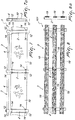
figures 1 and 1a are respectively side and front views of a modular fence structure according to the finding; -
figures 2 and 2a are respectively side and front views of a structural variant of the modular fence structure according to the finding; -
figures 3 and 3a are respectively side and front views of another structural variant of the modular fence structure according to the finding; -
figures 4 and 4a are respectively side and front views of another structural variant of the modular fence structure according to the finding; -
figures 5 and 5a are respectively side and front views of another structural variant of the modular fence structure according to the finding; -
figures 6 and 6a are respectively side and front views of another structural variant of the modular fence structure according to the finding; -
figures 7 and 7a are respectively side and front views of another structural variant of the modular fence structure according to the finding; -
figures 8 and 8a are respectively side and front views of another structural variant of the modular fence structure according to the finding; -
figure 9 is a perspective view of several components of a modular fence structure according to the finding; -
figure 10 is a perspective view of several components of a modular fence structure according to the finding; -
figure 11 is a side view with parts in section of a ground fixing system for an upright for a fence structure not in accordance with the present invention; -
figure 12 is a top view of an upright of the system offigure 11 ; and -
figure 13 is a view of a detail in enlarged scale of the system offigure 11 ; -
figure 14 is a side view with parts in section of another ground fixing system for an upright for a fence structure not in accordance with the present invention; -
figure 15 is a side view with parts in section of a further ground fixing system for an upright for a fence structure in accordance with the present invention; -
figure 16 is a side view with parts in section of another ground fixing system for an upright for a fence structure in accordance with the present invention; -
figure 17 is a top view of an upright of the system offigure 16 ; -
figure 18 is a view of a detail in enlarged scale of the system offigure 16 . - With reference to the abovementioned
figures 1 to 7 , as well as tofigure 9 , a modular fence structure is indicated in its entirety with thereference number 1. - The
structure 1 is essentially composed of a series ofuprights 2 suitable for a vertical fixing to the ground and conceived for supportingtransverse containment elements 3. - More particularly, the
uprights 2 are constituted by metal tubular bodies preferably made of COR-TEN steel, or of other materials with substantially analogous characteristics, which can have substantially circular or polygonal cross section, in accordance with the requirements. - It should be considered that the selection of COR-TEN steel, among the various available materials, is determined by the desire to intervene on the territory with minimum environmental and landscape impact, without however compromising the strength of the
structure 1 as well as its ease of assembly. - With regard to the
containment elements 3, these can instead have different configurations dictated by aesthetic and/or functional requirements. - In the case of
figures 1 and 2 , for example, thecontainment elements 3 are constituted bystringers 4, preferably made of wood or round, semi-round or square steel, jointed to theuprights 2 and arranged on one or more superimposed horizontal rows. - Advantageously, the
stringers 4 are combined withoblique crosspieces 5, preferably made of half-round or square wood, associated with theuprights 2 and arranged as St. Andrew's Cross. - It will nevertheless be clear to the man skilled in the art that the
containment elements 3 can also assume other configurations, which still fall within the scope of the present finding. - For example, as illustrated in
figures 3 and 4 , thecontainment elements 3 can be constituted bymetal rods 6, preferably made of COR-TEN steel, joined to theuprights 2 and equipped with vertically arrangedboards 7. - In other contexts, the
containment elements 3 can instead consist of gridlike modular panels, as illustrated as an example infigures 5 and 6 in which they are respectively indicated with thereference numbers cover panels 10, transparent or not transparent, as illustrated infigure 7 . - Clearly, the
containment elements 3 could also be constituted by nets, ropes, windbreak panels, and still other items, without departing from the scope of the employed solution idea. - According to the present finding, along the extension of the
uprights 2,shaped notches 11 can be defined which allow quickly and safely connecting thecontainment elements 3. - Advantageously, some or all of the
shaped notches 11 illustrated infigures 1 to 7 , as well as infigure 9 , have a shape substantially complementary to that of the cross section ofsuitable fixing elements 12, which are made integral with thecontainment elements 3 and associable with theuprights 2. - In practice, diametrically-opposed pairs of
shaped notches 11 define through seats for thefixing elements 12 on theuprights 2, which are inserted therein, with possibility of sliding in a manner such to traverse thesame uprights 2 from side to side, projecting from opposite sides. - By complementary, it is clearly to be intended that the
shaped notches 11 have size corresponding to the cross section of thefixing elements 12, such that one or eachfixing elements 12 is insertable to size, hence substantially without clearance, in the respectiveshaped notch 11. - Therefore, the complementarity between a
shaped notch 11 and a respective fixing element means that only arespective fixing element 12 is insertable in theshaped notch 11 or in each of theshaped notches 11 and therefore not a containment element to be supported, whose ends are thus not inserted in the axial opening of respective uprights. Among other things, this ensures stronger uprights as well as a quick and effective insertion of thefixing element 12 in theshaped notch 11, as well as the maintenance in correct work position of thefixing element 12, in particular as long as the same is not connected or fixed to one or more containment elements. - More particularly, the pairs of
shaped notches 11 are defined on the side of theuprights 2, at the top part and bottom part, i.e. substantially at the two opposite ends of the portions of theuprights 2 that project from the ground. - In the case of the embodiments of the structure according to the finding illustrated in
figures 1 to 7 , as well as infigure 9 , theshaped notches 11 are advantageously elongated slots defined longitudinally or transversely with respect to theuprights 2. - In other words, the aforesaid elongated slots can be defined in a manner such to be operatively vertical or operatively horizontal in accordance with the requirements.
- The
fixing elements 12 instead consist of a series of metal plates, preferably made of COR-TEN steel, which suitably have slottedholes 13 made on the opposite ends thereof. - The slotted
holes 13 allow fixing thecontainment elements 3 to the aforesaid plates by means ofscrews 14, bolts, rivets, or other equivalent connection members. - Suitably, such plates can also comprise mechanical blocks, constituted for example by projections that project from their profile, which fix the length of the plate sections insertable in the
shaped notches 11 and block the sliding thereof relative to theuprights 2. - The
uprights 2 can also compriseholes 15, orgrooves 16, conceived in a manner such to receive the ends of thestringers 4. - Based on an embodiment variant, illustrated as an example in
figures 8 and10 , in which the structure according to the finding is indicated withreference number 101, the shaped notches can assume a different shape. - More particularly, some or all the
shaped notches 111 can be substantially H-shaped, in a manner so as to definewings 17 on the front of theuprights 2,such wings 17 being susceptible of being bent towards each other, in a manner such to substantially form flat connection zones where it is possible to easily set and fix thecontainment elements 3. - Advantageously, at the
wings 17,bending raisers 18 can be provided that are essentially constituted by perforated slits. - In this case, the
containment elements 3 can be constituted bybars 19, preferably made of round, semi-round or square wood, joined to thewings 17 by means of self-drilling screws. - For the embodiment variant illustrated in
figures 8 and10 , the elements that correspond to the above-described elements with reference to the embodiment illustrated infigures 1 to 7 , as well as infigure 9 , the same reference numbers were employed. - It is important to underline that, irrespective of the form of the shaped notches, independently from the fact that they have an elongated slot or are H-shaped, experimental tests and a careful analysis of the results have allowed preferring laser technology, among the various techniques usable in cutting the tubular bodies that constitute the
uprights 2. - Such technology in fact allows working
uprights 2 with different profiles, rounded or polygonal, obtaining considerable advantages in the innovation of the production process and in the high quality level. - In particular, the use of the laser in cutting the
uprights 2 allows executing complex cutting lines with high precision, reducing both the times for making the fence according to the finding, and the working discards. - The assembly of the modular fence structure, according to the present finding, is particularly simple and quick.
- The structure is initially disassembled and its assembly starts with the installation of the
uprights 2 which represent the essential elements for supporting the entire structure. - For such purpose, it is considered that the
uprights 2 can be laid in various ways, for example by means of obtaining suitable concrete foundations, clamped with screws or screw anchors or by means of the pin system as represented in figures from 11 to 18. - Once the
uprights 2 are laid, it is possible to complete the structure by also mounting thecontainment elements 3. - More particularly, in the case of the
structure 1, after having installed thestringers 4, if present, one proceeds by inserting the fixingelements 12, i.e. the plates, in the shapednotches 11, in a manner such to make them project equally from the opposite sides of eachupright 2. - The exact positioning of the fixing
elements 12 can be facilitated by the mechanical blocks, already mentioned above. - When the fixing
elements 12 are correctly positioned, it is possible to block thecontainment elements 3 by means of thescrews 14, terminating the mounting of thestructure 1. - In the case of the
structure 101, instead, after having laid theuprights 2 one simple proceeds by fixing therods 19 to thewings 17 by means of self-drilling screws. - Such operation is clearly facilitated by the bending of the
wings 17, which in this manner come to define substantially flat connection zones where it is possible to set and constrain therods 19 with ease. - With reference now to
figures 11 to 15 , amodular fence structure 1a not in accordance with the present invention is illustrated, which comprises at least oneupright 2 adapted to support at least one transverse containment element (if desired, as indicated above with reference tofigures 1 to 10 ) and/or at least onestringer 4, for example as described above;such upright 2 is constituted by a tubular body, if desired metallic. - The
fence structure 1a then comprises at least one connection andsupport element 20, e.g. a bar or round bar or pin, if desired made of iron, for the connection, e.g. removable, to the ground S (seefigures 11 to 14 ) or to a curb or low C (seefigure 15 ) wall constrained or fixed to the ground S of theupright 2 and the support thereof; such connection andsupport element 20 is, on one side, connectable or fixable or fitted in the ground S or in a curb or low C wall and on the other side it is insertable or inserted in the throughhole 2a delimited by arespective upright 2 or in any case it can be arranged side-by-side or outside arespective upright 2. - Preferably, the connection and
support element 20 is arranged adjacent to and, if desired, in contact for the entire longitudinal extension thereof with theupright 2, in particular a lower, in use,internal surface section 2c of theupright 2. - In addition, the longitudinal extension axis of the connection and
support element 20 is preferably parallel to the longitudinal extension axis of therespective upright 2, for example vertical or substantially vertical. - The structure also comprises
means support element 20 with the upright or with therespective upright 2. - The means for constraining 21, 22 can comprise at least one U-shaped or C-shaped clamp or
bracket 21 enclosing or at least partially placed around the connection andsupport element 20 and with at least onefree end 21a inserted in and constrained to theupright 2 or to the lateral wall thereof. - If desired, one or both
free ends 21a of theclamp 21 is/are threaded and in such case the structure comprises at least one nut or a pair ofnuts 22, each in screwing engagement with a threadedfree end 21a; eachnut 22 preferably abuts against theexternal surface 2b of theupright 2, in particular if the connection andsupport element 20 is inserted in theupright 2 or against theinternal surface 2c of the upright, in particular if the connection andsupport element 20 flanks, from the outside, theupright 2, but in both cases such to constrain theupright 2 to theclamp 21 and to the connection andsupport element 20. - In substance, the clamp or bracket encloses the connection and
support element 20 and due to thenut 22 tightens - preferably removably - the connection andsupport element 20 against theexternal surface 2b orinternal surface 2c of theupright 2. - With one such structure it is possible to removably fix the
uprights 2 in the ground. To do this, one first installs or forcible fits the connection and supportelements 20 in the soil or ground, if desired by means of the use of pile-driver devices, for example in a layer of fresh concrete CL previously deposited on the or in the ground S or in dip formed or delimited by the ground S (seefigure 14 ), or one covers the connection and supportelements 20 with resin or glue and then the same are inserted or fixed in cement curbs or low walls C, in particular made of reinforced concrete, which curbs or low walls C have been previously constrained or fixed to the ground. - Subsequently, the tubular uprights are fixed, previously provided with holes by means of suitable clamps. In order to do so, the
upright 2 is arranged or inserted, in particular from above, about the connection andsupport element 20, i.e. in such a way as to make the connection andsupport element 20 to enter in the throughhole 2a delimited by theupright 2 and the connection andsupport element 20 is fixed to theupright 2 bymeans - Preferably, the bar or round bar or
pin 20 has a diameter or cross section lower than the diameter or cross section of thehole 2a delimited by the or arespective upright 2, for example between about 1/8 and about 1/2 or between about 1/6 and about 1/3 of the diameter or cross section of thehole 2a delimited by the or by a respective upright. - In this respect, the diameter of the pin 20 (if the same has circular section) could be equal to a value ranging between 10 and 40 mm, e.g. between 20 and 30 mm, preferably between 26 and 28 mm, whereas the diameter of the upright 2 (if the same has circular section) could be equal to a value ranging between 50 and 200 mm, e.g. between 60 and 150 mm. Clearly, the
pin 20 and/or theupright 2 could have section different with respect to the now indicated values. - Before using this system, one must evaluate the type of ground and suitably select the length of the pin.
- A structure or system like that illustrated in
figures 11 to 15 allows a removable mounting of one or more uprights and can for example be used for cleaning embankments and slopes or for a rapid removal of the installed system in case of emergencies (rescue, floods, overflows). - In addition, such system limits or prevents the deterioration of the metallic uprights, which, in conventional systems, are fixed to the ground and are not removable.
- In addition, if necessary it is possible to substitute the pin or
round bar 20, without having the substitute the entire fence. - Preferably, the
upright 2 is not fitted or inserted in the ground S or in a curb or small wall C, but it is for example laid thereon or raised, for example for 1-10 cm with respect thereto and supported, preferably only, by the connection andsupport element 20, with the aim of preventing theupright 2, in particular if the same is made of COR-TEN, from coming into contact with the water, which is usually present in the ground. - The pin or
round bar 20 can also be made of a traditional steel lined for reinforced concrete, which can have anti-rotation characteristics and be knurled, in which case it ensures an increased adherence both to the ground and with regard to the surface of therespective upright 2. - In addition, the
uprights 2 and thestringers 3 are obtained by means of laser technology and do not require subsequent working, in particular manual workshop working, e.g. welding, perforating, smoothing etcetera. - The pin or
round bar 20 can have length equal to about 20-120 cm, for example about 80-120 cm, if desired 100 cm for fixing on the ground, or for example 20-60 cm, if desired 40 cm for fixing on concrete. - The
pin 20 can be fitted or inserted for about 70-90% of its length, e.g. 80%, in the ground or about 40-60% of its length, e.g. 50%, in concrete. - With reference now to
figures 16 to 18 , a modular fence structure 1b according to the present invention has been shown, similar to that illustrated with respect tofigures 11 to 15 , but in which the connection and support element comprises a section bar or post 200, for example made of steel, such as UNP 65 - S275JR steel, if desired having a U-shaped section, in particular having a U-shaped cross section, in use, horizontal. - More particularly, the section bar or post 200 can include a
main sheet 200a with two edges or wings 200b folded, for example by 90° with respect to themain sheet 200a. The section bar or post 200 is inserted in theupright 2 with main or longitudinal extension axis parallel or substantially parallel to the main longitudinal axis or longitudinal symmetry axis of theupright 2 and it is then constrained thereto with themain sheet 200a having ends in contact with respective segments of theinternal surface 2c of the upright and if desired edges or wings 200b extending from such position towards the center or inner of theaxial hole 2a of theupright 2, or in contact with respective segments of theexternal surface 2b of theupright 2 and if desired edges or wings 200b extending from such position moving away from theupright 2. - As an alternative, the section bar or post 200 can be located side-by-side or outside a
respective upright 2. - The means for constraining or engaging 24 of the connection and
support element 200 to theupright 2 can instead include a screw orbolt 24a engageable with one or a pair of nuts 24b, 24c or similar means. The bolt or screw 24a of the means for constraining or engaging 24 is caused to pass throughout theupright 2 and throughout themain sheet 200a, if provided, and for example constrained to each of them by means of arespective nut - According to the not limiting embodiment shown in the figures, a
first nut 24b is provided for constraining or tightening thescrew 24a to themain sheet 200a and asecond nut 24c is provided for constraining or tightening thescrew 24a to theupright 2. - The section bar or post 200 can delimit first slots (not shown in the drawings) having for example main extension, in use, vertical, whereas the
upright 2 can include second slots (not shown in the drawings) having for example main extension, in use, horizontal and partially aligned with the slots in the section bar or post 200 for the insertion of screws orbolts 24a of the means for constraining or engaging 24, so that it is possible to arrange bidirectional adjustments for the alignment or installation of the fence 1b. Of course, as an alternative the first slots could be with horizontal main extension and the second slots could be with vertical main extension. - The vertical slots are also needed because the pile driver machine cannot have a millimetric precision on the insertion depth.
- The solution shown in
figures 16 to 18 is particularly adapted for installing long parts of fence and by means of a so called pile driver machine it is possible to shorten the laying times, without the need to make excavations or placing cement. - Moreover, the U-shaped section of the
section bar 200 is such as to increase the cohesion with the surrounding ground and, as soon as such section bar has been inserted, the same is almost unmovable. Moreover, the specific configuration of its cross section is such to render it static and with no elasticity. - A
section bar 200 could have length between about 0.5 and 2.5 m, for example between 1 and 1.5 m. - The
section 200 can be fitted or inserted for about 70-90% of its length, e.g. 80%, in the ground. - The thickness of the
main sheet 200a can vary between 4 and 8 mm, for example between 5 and 6 mm; if desired such thickness is equal to 5.5. - The thickness of the edges or wings 200b can vary between 6 and 10 mm, for example between 7 and 8 mm; if desired such thickness is equal to 7.5.
- The length of the edges or wings 200b is, preferably, equal or lower than the radius or half the width of the
upright 2. - The thickness of the
section bar 200, even without surface treatments, ensures a long time duration before the material deteriorates or loses mechanical resistance. - Moreover, the section of the
section bar 200 has shown to be suitable for the insertion or fixing in the ground S by means of a pile driver machine, since thesection bar 200 does not undergo deformation while it is installed by such machine. - Preferably, even in such case the
upright 2 is not fitted or inserted in the ground S or in a curb or small wall C, but it is for example laid thereon or raised, for example for 1-10 cm with respect thereto and supported by the connection andsupport element 200, this with the aim of preventing theupright 2, in particular if the same is made of COR-TEN, from coming into contact with the water, which is usually present in the ground. The bae of theupright 2 could for example be concealed by means of a grass layer G above the ground S. - In order to fix in the ground a fence structure as now described, first the connection and
support element 200 is fitted or inserted, for example by means of a pile driver machine, in the soil or ground S or in a curb or small wall C constrained or fixed to the ground S. - Subsequently, the
upright 2 is arranged around or side-by-side to the connection andsupport element 200, for example with connection andsupport element 200 inside the throughhole 2a delimited by theupright 2, and then the connection andsupport element 200 is fixed to theupright 2 by means of the means for constraining or engaging 24. - As above indicated, advantageously the
upright 2 is not fitted or inserted in the ground S or in a curb or small wall C, but it is laid thereon or raised with respect thereto and supported, preferably only, by the connection andsupport element 200 and by the means for constraining or engaging 24. - Clearly, the
fence structures 1a and 1b illustrated infigures 11 to 18 could include a plurality of uprights, e.g. as illustrated infigures 1 to 10 , all or only some among such uprights could be removably connected to the ground by means of a connection andsupport element - In practice, it has been established that the modular fence structure, according to the finding, fully achieves the pre-established task and objects.
- In particular, it is evident that the structure according to the finding is simple to achieve and assembly, even if comprising components made with heterogeneous materials.
- Part of the structure according to the finding is in fact made of COR-TEN steel and therefore is capable both of self-protection from electrochemical corrosion, with undoubted advantages in terms of fence duration and safety, and of maintaining low environmental and landscape impact.
- It should also be underlined that due to its particular structural features, the structure according to the finding offers the possibility of considerably increasing the array of attainable configurations, substantially starting from the same structural components.
- In addition, it is underlined that in the structure according to the finding the metal components present do not require welding, and this considerably reduces the labor costs during achievement.
- Another advantage of the modular fence structure according to the finding lies in the reduced bulk of the disassembled components; such property facilitates both the storage and the transport.
- As then regards the formation of the protective layer in uprights made of COR-TEN steel according to the present invention, the same forms following alternate cycles of dry and wet.
- If such upright is fitted in the ground, one would risk to limit or prevent the protective layer from occurring, in particular in the portion to be fitted.
- The fence structures shown in
figures 11 to 18 ensure instead a stable and safe fixing of an upright making it possible, among the other things, an optimum formation of the protective layer thereon, if an upright made of COR-TEN steel is used. - The modular fence structure thus conceived is susceptible of numerous modifications and variants, all falling within the scope of the inventive concept; in addition, all details can be substituted by other technically equivalent elements.
- In practice, the materials used, as long as they are compatible with the specific use, as well as the contingent shapes and sizes, can vary in accordance with the requirements and with the state of the art.
Claims (10)
- Modular fence structure, comprising at least one upright (2) adapted to support at least one transverse containment element (3, 4, 6, 8, 9, 10, 19) and/or at least one stringer (4), said at least one upright (2) being constituted by a tubular body, characterized in that it comprises at least one connection and support element (200) of said at least one upright (2) for the connection, e.g. removable, of said at least one upright (2) to the ground (S) or in a curb or low wall (B) constrained to the ground (S) as well as the support of said at least one upright (2), said at least one connection and support element (200) being, on one side, connectable or fixable or fitted in the ground (S) or in a curb or low wall (B) and on the other side it is insertable or inserted in the through hole (2a) delimited by a respective upright (2) or it is arranged side-by-side or outside a respective upright (2), said structure also comprising means for constraining or engaging (24) said at least one connection and support element (200) with said at least one upright (2), wherein said at least one connection and support element comprises a section bar or post (200) with U-shaped section and including a main sheet (200a) with two edges or wings (200b) folded with respect to the main sheet (200a), said section bar or post (200) being inserted in said at least one upright (2) or it is located side-by-side or outside said at least one upright (2), andwherein said section bar or post (200) delimits first slots having main extension, in use, vertical, whereas said at least one upright (2) delimits second slots having main extension, in use, horizontal and partially aligned with the first slots in the section bar or post (200) for the insertion of a screw or bolt (24a) of the means for constraining or engaging (24), so that it is possible to arrange bidirectional adjustments for the installation of the fence, orwherein said section bar or post (200) delimits first slots having main extension, in use, horizontal, whereas said at least one upright (2) delimits second slots having main extension, in use, vertical and partially aligned with the first slots in the section bar or post (200) for the insertion of a screw or bolt (24a) of the means for constraining or engaging (24), so that it is possible to arrange bidirectional adjustments for the installation of the fence.
- Structure according to claim 1, characterized in that said at least one connection and support element (200) comprises a round bar or a bar.
- Structure according to claim 1 or 2, wherein said main sheet (200a) has its ends in contact with respective segments of the internal surface (2c) or the external surface (2b) of the upright (2).
- Structure according to any previous claim, wherein said means for constraining or engaging (24) include a screw or bolt (24a) engageable with one or a pair of nuts (24b, 24c).
- Structure as claimed in claim 4, wherein a first nut (24b) is provided for constraining or tightening the screw (24a) to the main sheet (200a) and a second nut (24c) is provided for constraining or tightening the screw (24a) to the upright (2).
- Structure as claimed in any previous claim, wherein said at least one upright comprising a plurality of uprights (2) adapted to support a plurality of transverse containment elements (3, 4, 6, 8, 9, 10, 19), said uprights (2) being constituted by metal tubular bodies, said structure being characterized in that said uprights (2) comprise a plurality of shaped notches (11, 111), made along the extension thereof, adapted to allow the quick and safe connection of said containment elements (3, 4, 6, 8, 9, 10, 19).
- Structure according to one or more of the preceding claims, characterized in that said at least one upright (2) is made of COR-TEN steel.
- Method for fixing in the ground a fence structure as claimed in any previous claim, comprising the following steps:- fitting or inserting said at least one connection and support element (200) in the soil (S) or in a curb or small wall (C) constrained or fixed to the ground (S);- arranging said at least one upright (2) around or side-by-side to said at least one connection and support element (200), and- fixing said at least one connection and support element (200) to said at least one upright (2) through means for constraining or engaging (24).
- Method as claimed in claim 8, wherein said at least one upright (2) is not fitted or inserted in the ground (S) or in a curb or small wall (C), but it is laid thereon or raised with respect thereto and supported by said at least one connection and support element (200) and by said means for constraining or engaging (24).
- Method as claimed in claim 8 or 9, wherein said at least one connection and support element (200) is fitted or inserted in the soil (S) or in a curb or small wall (C) constrained or fixed to the ground (S) by means of a pile driver machine.
Applications Claiming Priority (2)
| Application Number | Priority Date | Filing Date | Title |
|---|---|---|---|
| EP16180830.8A EP3133228B1 (en) | 2015-07-22 | 2016-07-22 | A modular fence assembly |
| EP17181527.7A EP3272971B1 (en) | 2016-07-22 | 2017-07-14 | A fence assembly |
Related Parent Applications (2)
| Application Number | Title | Priority Date | Filing Date |
|---|---|---|---|
| EP17181527.7A Division EP3272971B1 (en) | 2016-07-22 | 2017-07-14 | A fence assembly |
| EP17181527.7A Division-Into EP3272971B1 (en) | 2016-07-22 | 2017-07-14 | A fence assembly |
Publications (3)
| Publication Number | Publication Date |
|---|---|
| EP3683385A2 true EP3683385A2 (en) | 2020-07-22 |
| EP3683385A3 EP3683385A3 (en) | 2020-09-02 |
| EP3683385B1 EP3683385B1 (en) | 2021-10-27 |
Family
ID=59296789
Family Applications (2)
| Application Number | Title | Priority Date | Filing Date |
|---|---|---|---|
| EP20160009.5A Active EP3683385B1 (en) | 2016-07-22 | 2017-07-14 | A modular fence assembly |
| EP17181527.7A Active EP3272971B1 (en) | 2016-07-22 | 2017-07-14 | A fence assembly |
Family Applications After (1)
| Application Number | Title | Priority Date | Filing Date |
|---|---|---|---|
| EP17181527.7A Active EP3272971B1 (en) | 2016-07-22 | 2017-07-14 | A fence assembly |
Country Status (1)
| Country | Link |
|---|---|
| EP (2) | EP3683385B1 (en) |
Families Citing this family (3)
| Publication number | Priority date | Publication date | Assignee | Title |
|---|---|---|---|---|
| BR202019026975U2 (en) * | 2019-12-17 | 2021-06-29 | Diviaves Equipamentos Para Aviário Ltda Me | PROVISIONS APPLIED IN DIVIDING GRID AND ITS CONNECTION ELEMENTS |
| BR202020003450U2 (en) * | 2020-02-19 | 2021-08-31 | Diviaves Equipamentos Para Aviário Ltda Me | EXPANSIVE DIVIDING GRID AND ITS CONNECTION ELEMENTS |
| CN115095226B (en) * | 2022-06-05 | 2023-11-14 | 中建八局第三建设有限公司 | Light high-large fence and erection method |
Citations (4)
| Publication number | Priority date | Publication date | Assignee | Title |
|---|---|---|---|---|
| US666947A (en) | 1899-12-21 | 1901-01-29 | Joseph T Ward | Fence-joint. |
| US4813651A (en) | 1988-06-30 | 1989-03-21 | Rutledge Terry G | Fence post with saddle support construction and method therefore |
| DE4436345C1 (en) | 1994-10-12 | 1996-02-08 | V & S Sicherungssysteme Gmbh & | Lattice fence with locking retainer bars |
| US20030222257A1 (en) | 2001-06-05 | 2003-12-04 | Bebendorf Ronald William | Fence post and rail assembly with concealed strengthening bars |
Family Cites Families (9)
| Publication number | Priority date | Publication date | Assignee | Title |
|---|---|---|---|---|
| FR442350A (en) * | 1911-03-08 | 1912-08-29 | Louis Martenet | Foot for poles supporting power lines |
| US3011597A (en) * | 1958-04-21 | 1961-12-05 | William H Galloway | Supporting post |
| DE7613214U1 (en) * | 1976-04-27 | 1987-10-15 | Gebrueder Koemmerling Kunststoffwerke Gmbh, 6780 Pirmasens, De | |
| CH680519A5 (en) * | 1988-03-25 | 1992-09-15 | Jean Louis Uldry | Metal support, esp. for timber fencing post - comprises rings for post attached to central metal spike and splayed supporting rods |
| US5671584A (en) * | 1996-08-28 | 1997-09-30 | Mueller; John F. | Method and apparatus for constructing a retaining wall |
| US20050269558A1 (en) * | 2004-06-04 | 2005-12-08 | Keefe James P | System and apparatus for reinforcing fence components |
| CH698163B1 (en) * | 2006-10-11 | 2009-06-15 | Atrena Ag | Fencepost. |
| WO2008114031A1 (en) * | 2007-03-21 | 2008-09-25 | Vincent Michael Demarest | Improvements in and relating to pile driving |
| FR2974834B1 (en) * | 2011-05-04 | 2013-05-31 | Maxilor | DEVICE COMPRISING A CLOSURE POST, CONSISTING OF AN ESSENTIALLY TUBULAR PROFILE, AND A BASE AT LEAST PARTIALLY BOTTOMED IN THE GROUND |
-
2017
- 2017-07-14 EP EP20160009.5A patent/EP3683385B1/en active Active
- 2017-07-14 EP EP17181527.7A patent/EP3272971B1/en active Active
Patent Citations (4)
| Publication number | Priority date | Publication date | Assignee | Title |
|---|---|---|---|---|
| US666947A (en) | 1899-12-21 | 1901-01-29 | Joseph T Ward | Fence-joint. |
| US4813651A (en) | 1988-06-30 | 1989-03-21 | Rutledge Terry G | Fence post with saddle support construction and method therefore |
| DE4436345C1 (en) | 1994-10-12 | 1996-02-08 | V & S Sicherungssysteme Gmbh & | Lattice fence with locking retainer bars |
| US20030222257A1 (en) | 2001-06-05 | 2003-12-04 | Bebendorf Ronald William | Fence post and rail assembly with concealed strengthening bars |
Also Published As
| Publication number | Publication date |
|---|---|
| EP3683385A3 (en) | 2020-09-02 |
| EP3683385B1 (en) | 2021-10-27 |
| EP3272971A1 (en) | 2018-01-24 |
| EP3272971B1 (en) | 2021-09-01 |
Similar Documents
| Publication | Publication Date | Title |
|---|---|---|
| US7913463B2 (en) | Adjustable vertical brace | |
| EP3683385B1 (en) | A modular fence assembly | |
| US8528275B2 (en) | Ground anchor with adjustable positioning member | |
| US4260293A (en) | Floating dock structure and method for fabricating the same | |
| EP3045605B1 (en) | Module for producing concrete elements | |
| US20100295007A1 (en) | Safety barriers | |
| US20110233496A1 (en) | Modular fence | |
| US20060188336A1 (en) | Adjustable support bracket for concrete reinforcing bars | |
| EP3133228B1 (en) | A modular fence assembly | |
| FI66232C (en) | BAERANORDNING FOR FOUNDATION | |
| CA2889001A1 (en) | Elevated equipment assemblies, equipment-supporting platforms, and related methods | |
| KR100566721B1 (en) | Prefab type land-side protection wall device | |
| KR101777746B1 (en) | A support | |
| DE6603496U (en) | FORMWORK FOR THE PRODUCTION OF CONTAINER-SHAPED CONCRETE STRUCTURES, SUCH AS SILOS OR THE LIKE. | |
| KR200430532Y1 (en) | A combination structure of guardrail pipe | |
| RU164562U1 (en) | BRACKET FOR FASTENING LOGS TO THE FENGTH POST | |
| GB2459486A (en) | Fence post | |
| EP2189597A1 (en) | A temporary metal fence for restricting access | |
| KR102370425B1 (en) | The safety rail of the formwork | |
| RU148524U1 (en) | FENCE BAR (OPTIONS) | |
| KR102201160B1 (en) | Handrail for landscape facilities and deck | |
| DE102020116734B4 (en) | Horde gate | |
| KR200468811Y1 (en) | A Prefabricated boundary-fence | |
| AU2002301841B2 (en) | A Method of Construction | |
| KR970005544Y1 (en) | Device for tying forms |
Legal Events
| Date | Code | Title | Description |
|---|---|---|---|
| PUAI | Public reference made under article 153(3) epc to a published international application that has entered the european phase |
Free format text: ORIGINAL CODE: 0009012 |
|
| STAA | Information on the status of an ep patent application or granted ep patent |
Free format text: STATUS: THE APPLICATION HAS BEEN PUBLISHED |
|
| AC | Divisional application: reference to earlier application |
Ref document number: 3272971 Country of ref document: EP Kind code of ref document: P |
|
| AK | Designated contracting states |
Kind code of ref document: A2 Designated state(s): AL AT BE BG CH CY CZ DE DK EE ES FI FR GB GR HR HU IE IS IT LI LT LU LV MC MK MT NL NO PL PT RO RS SE SI SK SM TR |
|
| REG | Reference to a national code |
Ref country code: DE Ref legal event code: R079 Ref document number: 602017048557 Country of ref document: DE Free format text: PREVIOUS MAIN CLASS: E04H0017140000 Ipc: E04H0012220000 |
|
| PUAL | Search report despatched |
Free format text: ORIGINAL CODE: 0009013 |
|
| AK | Designated contracting states |
Kind code of ref document: A3 Designated state(s): AL AT BE BG CH CY CZ DE DK EE ES FI FR GB GR HR HU IE IS IT LI LT LU LV MC MK MT NL NO PL PT RO RS SE SI SK SM TR |
|
| RIC1 | Information provided on ipc code assigned before grant |
Ipc: E04H 17/22 20060101ALI20200728BHEP Ipc: E04H 12/22 20060101AFI20200728BHEP |
|
| STAA | Information on the status of an ep patent application or granted ep patent |
Free format text: STATUS: REQUEST FOR EXAMINATION WAS MADE |
|
| 17P | Request for examination filed |
Effective date: 20210107 |
|
| RBV | Designated contracting states (corrected) |
Designated state(s): AL AT BE BG CH CY CZ DE DK EE ES FI FR GB GR HR HU IE IS IT LI LT LU LV MC MK MT NL NO PL PT RO RS SE SI SK SM TR |
|
| GRAP | Despatch of communication of intention to grant a patent |
Free format text: ORIGINAL CODE: EPIDOSNIGR1 |
|
| STAA | Information on the status of an ep patent application or granted ep patent |
Free format text: STATUS: GRANT OF PATENT IS INTENDED |
|
| INTG | Intention to grant announced |
Effective date: 20210517 |
|
| GRAS | Grant fee paid |
Free format text: ORIGINAL CODE: EPIDOSNIGR3 |
|
| GRAA | (expected) grant |
Free format text: ORIGINAL CODE: 0009210 |
|
| STAA | Information on the status of an ep patent application or granted ep patent |
Free format text: STATUS: THE PATENT HAS BEEN GRANTED |
|
| AC | Divisional application: reference to earlier application |
Ref document number: 3272971 Country of ref document: EP Kind code of ref document: P |
|
| AK | Designated contracting states |
Kind code of ref document: B1 Designated state(s): AL AT BE BG CH CY CZ DE DK EE ES FI FR GB GR HR HU IE IS IT LI LT LU LV MC MK MT NL NO PL PT RO RS SE SI SK SM TR |
|
| REG | Reference to a national code |
Ref country code: GB Ref legal event code: FG4D |
|
| REG | Reference to a national code |
Ref country code: CH Ref legal event code: EP |
|
| REG | Reference to a national code |
Ref country code: AT Ref legal event code: REF Ref document number: 1441931 Country of ref document: AT Kind code of ref document: T Effective date: 20211115 |
|
| REG | Reference to a national code |
Ref country code: DE Ref legal event code: R096 Ref document number: 602017048557 Country of ref document: DE |
|
| REG | Reference to a national code |
Ref country code: IE Ref legal event code: FG4D |
|
| REG | Reference to a national code |
Ref country code: NL Ref legal event code: FP |
|
| REG | Reference to a national code |
Ref country code: LT Ref legal event code: MG9D |
|
| REG | Reference to a national code |
Ref country code: AT Ref legal event code: MK05 Ref document number: 1441931 Country of ref document: AT Kind code of ref document: T Effective date: 20211027 |
|
| PG25 | Lapsed in a contracting state [announced via postgrant information from national office to epo] |
Ref country code: RS Free format text: LAPSE BECAUSE OF FAILURE TO SUBMIT A TRANSLATION OF THE DESCRIPTION OR TO PAY THE FEE WITHIN THE PRESCRIBED TIME-LIMIT Effective date: 20211027 Ref country code: LT Free format text: LAPSE BECAUSE OF FAILURE TO SUBMIT A TRANSLATION OF THE DESCRIPTION OR TO PAY THE FEE WITHIN THE PRESCRIBED TIME-LIMIT Effective date: 20211027 Ref country code: FI Free format text: LAPSE BECAUSE OF FAILURE TO SUBMIT A TRANSLATION OF THE DESCRIPTION OR TO PAY THE FEE WITHIN THE PRESCRIBED TIME-LIMIT Effective date: 20211027 Ref country code: BG Free format text: LAPSE BECAUSE OF FAILURE TO SUBMIT A TRANSLATION OF THE DESCRIPTION OR TO PAY THE FEE WITHIN THE PRESCRIBED TIME-LIMIT Effective date: 20220127 Ref country code: AT Free format text: LAPSE BECAUSE OF FAILURE TO SUBMIT A TRANSLATION OF THE DESCRIPTION OR TO PAY THE FEE WITHIN THE PRESCRIBED TIME-LIMIT Effective date: 20211027 |
|
| PG25 | Lapsed in a contracting state [announced via postgrant information from national office to epo] |
Ref country code: IS Free format text: LAPSE BECAUSE OF FAILURE TO SUBMIT A TRANSLATION OF THE DESCRIPTION OR TO PAY THE FEE WITHIN THE PRESCRIBED TIME-LIMIT Effective date: 20220227 Ref country code: SE Free format text: LAPSE BECAUSE OF FAILURE TO SUBMIT A TRANSLATION OF THE DESCRIPTION OR TO PAY THE FEE WITHIN THE PRESCRIBED TIME-LIMIT Effective date: 20211027 Ref country code: PT Free format text: LAPSE BECAUSE OF FAILURE TO SUBMIT A TRANSLATION OF THE DESCRIPTION OR TO PAY THE FEE WITHIN THE PRESCRIBED TIME-LIMIT Effective date: 20220228 Ref country code: PL Free format text: LAPSE BECAUSE OF FAILURE TO SUBMIT A TRANSLATION OF THE DESCRIPTION OR TO PAY THE FEE WITHIN THE PRESCRIBED TIME-LIMIT Effective date: 20211027 Ref country code: NO Free format text: LAPSE BECAUSE OF FAILURE TO SUBMIT A TRANSLATION OF THE DESCRIPTION OR TO PAY THE FEE WITHIN THE PRESCRIBED TIME-LIMIT Effective date: 20220127 Ref country code: LV Free format text: LAPSE BECAUSE OF FAILURE TO SUBMIT A TRANSLATION OF THE DESCRIPTION OR TO PAY THE FEE WITHIN THE PRESCRIBED TIME-LIMIT Effective date: 20211027 Ref country code: HR Free format text: LAPSE BECAUSE OF FAILURE TO SUBMIT A TRANSLATION OF THE DESCRIPTION OR TO PAY THE FEE WITHIN THE PRESCRIBED TIME-LIMIT Effective date: 20211027 Ref country code: ES Free format text: LAPSE BECAUSE OF FAILURE TO SUBMIT A TRANSLATION OF THE DESCRIPTION OR TO PAY THE FEE WITHIN THE PRESCRIBED TIME-LIMIT Effective date: 20211027 |
|
| REG | Reference to a national code |
Ref country code: DE Ref legal event code: R097 Ref document number: 602017048557 Country of ref document: DE |
|
| PG25 | Lapsed in a contracting state [announced via postgrant information from national office to epo] |
Ref country code: SM Free format text: LAPSE BECAUSE OF FAILURE TO SUBMIT A TRANSLATION OF THE DESCRIPTION OR TO PAY THE FEE WITHIN THE PRESCRIBED TIME-LIMIT Effective date: 20211027 Ref country code: SK Free format text: LAPSE BECAUSE OF FAILURE TO SUBMIT A TRANSLATION OF THE DESCRIPTION OR TO PAY THE FEE WITHIN THE PRESCRIBED TIME-LIMIT Effective date: 20211027 Ref country code: RO Free format text: LAPSE BECAUSE OF FAILURE TO SUBMIT A TRANSLATION OF THE DESCRIPTION OR TO PAY THE FEE WITHIN THE PRESCRIBED TIME-LIMIT Effective date: 20211027 Ref country code: EE Free format text: LAPSE BECAUSE OF FAILURE TO SUBMIT A TRANSLATION OF THE DESCRIPTION OR TO PAY THE FEE WITHIN THE PRESCRIBED TIME-LIMIT Effective date: 20211027 Ref country code: DK Free format text: LAPSE BECAUSE OF FAILURE TO SUBMIT A TRANSLATION OF THE DESCRIPTION OR TO PAY THE FEE WITHIN THE PRESCRIBED TIME-LIMIT Effective date: 20211027 Ref country code: CZ Free format text: LAPSE BECAUSE OF FAILURE TO SUBMIT A TRANSLATION OF THE DESCRIPTION OR TO PAY THE FEE WITHIN THE PRESCRIBED TIME-LIMIT Effective date: 20211027 |
|
| PLBE | No opposition filed within time limit |
Free format text: ORIGINAL CODE: 0009261 |
|
| STAA | Information on the status of an ep patent application or granted ep patent |
Free format text: STATUS: NO OPPOSITION FILED WITHIN TIME LIMIT |
|
| 26N | No opposition filed |
Effective date: 20220728 |
|
| PG25 | Lapsed in a contracting state [announced via postgrant information from national office to epo] |
Ref country code: AL Free format text: LAPSE BECAUSE OF FAILURE TO SUBMIT A TRANSLATION OF THE DESCRIPTION OR TO PAY THE FEE WITHIN THE PRESCRIBED TIME-LIMIT Effective date: 20211027 |
|
| PG25 | Lapsed in a contracting state [announced via postgrant information from national office to epo] |
Ref country code: SI Free format text: LAPSE BECAUSE OF FAILURE TO SUBMIT A TRANSLATION OF THE DESCRIPTION OR TO PAY THE FEE WITHIN THE PRESCRIBED TIME-LIMIT Effective date: 20211027 |
|
| PG25 | Lapsed in a contracting state [announced via postgrant information from national office to epo] |
Ref country code: MC Free format text: LAPSE BECAUSE OF FAILURE TO SUBMIT A TRANSLATION OF THE DESCRIPTION OR TO PAY THE FEE WITHIN THE PRESCRIBED TIME-LIMIT Effective date: 20211027 |
|
| PG25 | Lapsed in a contracting state [announced via postgrant information from national office to epo] |
Ref country code: LU Free format text: LAPSE BECAUSE OF NON-PAYMENT OF DUE FEES Effective date: 20220714 |
|
| P01 | Opt-out of the competence of the unified patent court (upc) registered |
Effective date: 20230508 |
|
| PG25 | Lapsed in a contracting state [announced via postgrant information from national office to epo] |
Ref country code: IE Free format text: LAPSE BECAUSE OF NON-PAYMENT OF DUE FEES Effective date: 20220714 |
|
| PGFP | Annual fee paid to national office [announced via postgrant information from national office to epo] |
Ref country code: IT Payment date: 20230616 Year of fee payment: 7 |
|
| PGFP | Annual fee paid to national office [announced via postgrant information from national office to epo] |
Ref country code: NL Payment date: 20230726 Year of fee payment: 7 |
|
| PGFP | Annual fee paid to national office [announced via postgrant information from national office to epo] |
Ref country code: GB Payment date: 20230727 Year of fee payment: 7 Ref country code: CH Payment date: 20230802 Year of fee payment: 7 |
|
| PGFP | Annual fee paid to national office [announced via postgrant information from national office to epo] |
Ref country code: FR Payment date: 20230725 Year of fee payment: 7 Ref country code: DE Payment date: 20230727 Year of fee payment: 7 Ref country code: BE Payment date: 20230727 Year of fee payment: 7 |
|
| PG25 | Lapsed in a contracting state [announced via postgrant information from national office to epo] |
Ref country code: MK Free format text: LAPSE BECAUSE OF FAILURE TO SUBMIT A TRANSLATION OF THE DESCRIPTION OR TO PAY THE FEE WITHIN THE PRESCRIBED TIME-LIMIT Effective date: 20211027 Ref country code: CY Free format text: LAPSE BECAUSE OF FAILURE TO SUBMIT A TRANSLATION OF THE DESCRIPTION OR TO PAY THE FEE WITHIN THE PRESCRIBED TIME-LIMIT Effective date: 20211027 |