EP3683151B1 - Nacelle - Google Patents
Nacelle Download PDFInfo
- Publication number
- EP3683151B1 EP3683151B1 EP19218672.4A EP19218672A EP3683151B1 EP 3683151 B1 EP3683151 B1 EP 3683151B1 EP 19218672 A EP19218672 A EP 19218672A EP 3683151 B1 EP3683151 B1 EP 3683151B1
- Authority
- EP
- European Patent Office
- Prior art keywords
- nacelle
- nozzle
- pylon
- exhaust
- engine
- Prior art date
- Legal status (The legal status is an assumption and is not a legal conclusion. Google has not performed a legal analysis and makes no representation as to the accuracy of the status listed.)
- Active
Links
- 239000007789 gas Substances 0.000 description 35
- 239000003570 air Substances 0.000 description 15
- 239000000446 fuel Substances 0.000 description 11
- 230000009467 reduction Effects 0.000 description 5
- 230000003416 augmentation Effects 0.000 description 3
- 230000003247 decreasing effect Effects 0.000 description 3
- 238000000926 separation method Methods 0.000 description 3
- 238000004088 simulation Methods 0.000 description 3
- 230000008901 benefit Effects 0.000 description 2
- 238000006073 displacement reaction Methods 0.000 description 2
- 238000009826 distribution Methods 0.000 description 2
- 230000006872 improvement Effects 0.000 description 2
- 230000003993 interaction Effects 0.000 description 2
- 238000004519 manufacturing process Methods 0.000 description 2
- 239000002184 metal Substances 0.000 description 2
- 238000010008 shearing Methods 0.000 description 2
- 230000002411 adverse Effects 0.000 description 1
- 239000012080 ambient air Substances 0.000 description 1
- 230000015556 catabolic process Effects 0.000 description 1
- 230000008859 change Effects 0.000 description 1
- 239000002131 composite material Substances 0.000 description 1
- 238000006731 degradation reaction Methods 0.000 description 1
- 230000001419 dependent effect Effects 0.000 description 1
- 238000013461 design Methods 0.000 description 1
- 230000001627 detrimental effect Effects 0.000 description 1
- 230000000694 effects Effects 0.000 description 1
- 238000005304 joining Methods 0.000 description 1
- 238000000034 method Methods 0.000 description 1
- 230000000116 mitigating effect Effects 0.000 description 1
- 238000012986 modification Methods 0.000 description 1
- 230000004048 modification Effects 0.000 description 1
- 230000003472 neutralizing effect Effects 0.000 description 1
- 238000013021 overheating Methods 0.000 description 1
- 238000001228 spectrum Methods 0.000 description 1
- 238000012546 transfer Methods 0.000 description 1
Images


Classifications
-
- F—MECHANICAL ENGINEERING; LIGHTING; HEATING; WEAPONS; BLASTING
- F02—COMBUSTION ENGINES; HOT-GAS OR COMBUSTION-PRODUCT ENGINE PLANTS
- F02K—JET-PROPULSION PLANTS
- F02K3/00—Plants including a gas turbine driving a compressor or a ducted fan
- F02K3/02—Plants including a gas turbine driving a compressor or a ducted fan in which part of the working fluid by-passes the turbine and combustion chamber
- F02K3/04—Plants including a gas turbine driving a compressor or a ducted fan in which part of the working fluid by-passes the turbine and combustion chamber the plant including ducted fans, i.e. fans with high volume, low pressure outputs, for augmenting the jet thrust, e.g. of double-flow type
-
- F—MECHANICAL ENGINEERING; LIGHTING; HEATING; WEAPONS; BLASTING
- F02—COMBUSTION ENGINES; HOT-GAS OR COMBUSTION-PRODUCT ENGINE PLANTS
- F02K—JET-PROPULSION PLANTS
- F02K1/00—Plants characterised by the form or arrangement of the jet pipe or nozzle; Jet pipes or nozzles peculiar thereto
- F02K1/46—Nozzles having means for adding air to the jet or for augmenting the mixing region between the jet and the ambient air, e.g. for silencing
-
- B—PERFORMING OPERATIONS; TRANSPORTING
- B64—AIRCRAFT; AVIATION; COSMONAUTICS
- B64D—EQUIPMENT FOR FITTING IN OR TO AIRCRAFT; FLIGHT SUITS; PARACHUTES; ARRANGEMENT OR MOUNTING OF POWER PLANTS OR PROPULSION TRANSMISSIONS IN AIRCRAFT
- B64D33/00—Arrangements in aircraft of power plant parts or auxiliaries not otherwise provided for
- B64D33/04—Arrangements in aircraft of power plant parts or auxiliaries not otherwise provided for of exhaust outlets or jet pipes
-
- F—MECHANICAL ENGINEERING; LIGHTING; HEATING; WEAPONS; BLASTING
- F02—COMBUSTION ENGINES; HOT-GAS OR COMBUSTION-PRODUCT ENGINE PLANTS
- F02K—JET-PROPULSION PLANTS
- F02K1/00—Plants characterised by the form or arrangement of the jet pipe or nozzle; Jet pipes or nozzles peculiar thereto
- F02K1/002—Plants characterised by the form or arrangement of the jet pipe or nozzle; Jet pipes or nozzles peculiar thereto with means to modify the direction of thrust vector
-
- F—MECHANICAL ENGINEERING; LIGHTING; HEATING; WEAPONS; BLASTING
- F02—COMBUSTION ENGINES; HOT-GAS OR COMBUSTION-PRODUCT ENGINE PLANTS
- F02K—JET-PROPULSION PLANTS
- F02K1/00—Plants characterised by the form or arrangement of the jet pipe or nozzle; Jet pipes or nozzles peculiar thereto
- F02K1/06—Varying effective area of jet pipe or nozzle
- F02K1/15—Control or regulation
-
- F—MECHANICAL ENGINEERING; LIGHTING; HEATING; WEAPONS; BLASTING
- F02—COMBUSTION ENGINES; HOT-GAS OR COMBUSTION-PRODUCT ENGINE PLANTS
- F02K—JET-PROPULSION PLANTS
- F02K1/00—Plants characterised by the form or arrangement of the jet pipe or nozzle; Jet pipes or nozzles peculiar thereto
- F02K1/78—Other construction of jet pipes
-
- F—MECHANICAL ENGINEERING; LIGHTING; HEATING; WEAPONS; BLASTING
- F02—COMBUSTION ENGINES; HOT-GAS OR COMBUSTION-PRODUCT ENGINE PLANTS
- F02K—JET-PROPULSION PLANTS
- F02K3/00—Plants including a gas turbine driving a compressor or a ducted fan
- F02K3/02—Plants including a gas turbine driving a compressor or a ducted fan in which part of the working fluid by-passes the turbine and combustion chamber
- F02K3/04—Plants including a gas turbine driving a compressor or a ducted fan in which part of the working fluid by-passes the turbine and combustion chamber the plant including ducted fans, i.e. fans with high volume, low pressure outputs, for augmenting the jet thrust, e.g. of double-flow type
- F02K3/06—Plants including a gas turbine driving a compressor or a ducted fan in which part of the working fluid by-passes the turbine and combustion chamber the plant including ducted fans, i.e. fans with high volume, low pressure outputs, for augmenting the jet thrust, e.g. of double-flow type with front fan
-
- F—MECHANICAL ENGINEERING; LIGHTING; HEATING; WEAPONS; BLASTING
- F05—INDEXING SCHEMES RELATING TO ENGINES OR PUMPS IN VARIOUS SUBCLASSES OF CLASSES F01-F04
- F05D—INDEXING SCHEME FOR ASPECTS RELATING TO NON-POSITIVE-DISPLACEMENT MACHINES OR ENGINES, GAS-TURBINES OR JET-PROPULSION PLANTS
- F05D2260/00—Function
- F05D2260/96—Preventing, counteracting or reducing vibration or noise
Definitions
- the present disclosure relates to an exhaust system for an aircraft turbofan engine.
- FIG. 1 is a schematic view of an exemplary aircraft engine pod 60.
- Engine pod 60 includes a nacelle 62, a fan 64, a compressor 66, a combustor 68, and a turbine 70.
- Engine pod 60 is typically attached to the wings or fuselage of an aircraft through appropriate mountings, for example, a pylon 71.
- Nacelle 62 includes an engine inlet 72 having an outer barrel 74 and an inner barrel 76, and a lip section joining the two.
- the inner barrel 76 along with a lip section, defines an air intake duct 78 for supplying air 55 to the fan 64, which subsequently is directed both to the bypass duct and engine core, comprising the compressor 66, combustor 68 and turbine 70.
- FIG. 1 is a schematic view of an exemplary aircraft engine pod 60.
- Engine pod 60 includes a nacelle 62, a fan 64, a compressor 66, a combustor 68, and a turbine 70.
- Engine pod 60 is
- FIG. 2 is an end view of the engine pod 60 illustrating the external nacelle 202, fan duct 200 outer flow surface OFS, a fan duct inner flow surface IFS, an aft cowl 204 comprising an extension of the IFS beyond an aft station of the OFS, a core nozzle 205, and the plug 206 at maximum diameter, where each of the plug 206; core nozzle 205, aft cowl 204, OFS, and external nacelle 202 are concentrically nested about a longitudinal axis AA of the engine pod 60. Also shown are locations of the fan exhaust flow 210 and primary flow 212 (also known as core exhaust flow).
- Patent document FR 911 269 A relates to a propulsion system applicable to vehicles moving in the air, constituted by a jet of a gas hitting a surface oriented in such a way that it gives a propelling force.
- Patent document US 4 508 270 A relates to a directable nozzle comprising a fixed part bearing at its extremity a fixed interior spherical sliding surface against which an exterior movable spherical race of a cylindrical collar comprising the movable part of the nozzle can displace itself.
- Patent document US 4 066 214 A relates to an exhaust nozzle for exhausting the effluent of a turbofan gas turbine engine across a portion of the upper surface of an aircraft wing wherein the exhaust nozzle is arranged to establish a temperature profile within the exhausted gases that prevents overheating the wing surface.
- Patent document EP 1 690 790 A1 relates to fan turbine engine arrangement in which a core engine is aligned such that an input of a nacelle is aligned with the upwash of a wing to which the arrangement is secured.
- the engine drives a fan such that bypass flows produced by the fan are guided by a duct to present a downward component for uplift.
- the core engine presents its output flow through a nozzle which is aligned with the fundamental axis of the engine. In such circumstances, the bypass flows cross the core engine flow from the nozzle unless that engine is adjustable during operation in order to maintain alignment dependent upon lift requirements.
- Patent document US 3 658 279 A relates to a thrust vectoring, thrust reversing and lift augmentation system for jet aircraft to optimize the several controlled flight regimes of the aircraft.
- the pilot can direct and control the exhaust gases of each engine to give maximum forward thrust, boundary layer control and/or jet flap lift augmentation or he can select some combination of vectored thrust with lift augmentation.
- a thrust reversing position can be selected to minimize ground roll after landing of the aircraft.
- Patent document CN 208 310 917 U relates to a transfer section structure for manipulating the influence of an S-bend nozzle on a ducted ratio of a turbofan engine.
- Patent document US 6 415 598 B2 relates to a by-pass gas turbine engine including a primary and a secondary nozzle which are substantially convergent, wherein the primary nozzle is situated radially within, but axially protruding from, the secondary nozzle characterised in that the primary and secondary nozzles have a substantially common central axis along their lengths and the direction of airflow exiting at least one of the primary or secondary nozzles is at an angle to the central axis of the engine and that the direction of airflow exiting each nozzle is at an angle to the other thereby effecting distribution and mixing of the airflows.
- the end of both the primary and secondary nozzles may be truncated at oppositely orientated oblique angles.
- the internal profile of one or both nozzles may be arranged such that the airflow leaves the that nozzle at an angle to the axis of the nozzle.
- Patent document US 4 280 587 A relates to a discharge nozzle of a jet engine that has lobes, tubes or deflectors for effecting mixing of the engine discharge flow with ambient air to reduce jet noise.
- lobes, tubes or deflectors By providing the lobes, tubes or deflectors at the upper portion of the discharge nozzle, jet noise perceived below the engine is reduced without shifting the noise spectrum to include a higher proportion of high frequency noise components.
- the fan or secondary flow is discharged below the primary exhaust flow to reduce noise perceived below the turbofan.
- the presently claimed invention relates to a nacelle as claimed in claim 1.
- the present disclosure describes an engine including a nacelle having an inlet and an exhaust; a fan duct between the nacelle and an engine core housed in the nacelle, wherein the nacelle forms an outer wall (comprising outer flow surface OFS) of the fan duct; a casing of the engine core and an aft cowl form an inner wall (comprising inner flow surface IFS) of the fan duct; and an exit station of the OFS has a curved portion having a curvature so that the IFS and the OFS shift exhaust gas exiting the exhaust towards a longitudinal axis of the engine so as to fill an area behind the engine and counteract deflection of the exhaust gas caused by a pylon attached to the nacelle.
- the curvature may be controlled to contribute, at a given thrust generated by the turbofan engine, to community noise reduction experienced downstream of the engine and engine performance maximization (e.g., reduction in the fuel consumed in the engine housed in the nacelle).
- the curvature of the curved portion may be such that a first distance D1 (e.g., slant height) between a first point (P1) on the OFS, and a second point (P2) on inner flow surface (IFS), is larger or longer than a second distance D2 (e.g., slant height) between a third point (P3) on the OFS and a fourth point (P4) on the IFS.
- a first distance D1 e.g., slant height
- the first distance D1 is on an attach side of the pylon (i.e., in a first region R1 between the pylon and a core exhaust connected to the engine core) and the second distance D2 is in a second region R2 between the core exhaust and a section of the external nacelle (comprising the outer surface of the nacelle) that faces away from the aircraft.
- the first point, the second point, the third point, and the fourth point may be collinear.
- the curved portion includes a first shift in a position of the first point, P1, by approximately 1-2% of a diameter of the exhaust, as measured at the trailing edge of the exhaust, and a second shift in a position of the third point, P3, by approximately 1-2% of the diameter of the exhaust, as measured at the trailing edge of the exhaust, wherein the shifts are relative to the case where the core exhaust (e.g., core nand the exhaust (e.g., fan nozzle) are concentric. D1 is 1-2% longer and D2 is 1-2% shorter relative to what D1 and D2 would have been had the core nozzle been centered on the engine's longitudinal axis or center line.
- the core exhaust e.g., core nand the exhaust (e.g., fan nozzle
- the nacelle may comprise an external nacelle having a length L1, as measured in a direction parallel to the engine's longitudinal axis AA', and the curved portion is entirely within the last 25% of the length L1 of the external nacelle.
- the exhaust comprises a shear, or offset, of the fan duct outer wall so as to form the curved portion.
- the curved portion may increase alignment of a thrust vector of the thrust in an aft-facing direction parallel to a longitudinal axis of the engine so that the thrust deflected (e.g., down) by the pylon is shifted back towards or parallel to the longitudinal axis of the engine.
- the pylon attaches the nacelle to a wing.
- the pylon may attach the nacelle to a fuselage or an empennage.
- An exhaust for a nacelle may comprise a curved portion that shifts flow of gas exiting through the exhaust in a direction that counteracts displacement of the flow by a mounting structure (e.g., pylon) attached to the nacelle.
- a mounting structure e.g., pylon
- the exhaust comprises a nozzle including the curved portion so that, when the nozzle is disposed around a body and the flow of the gas between the nozzle and the body is bounded by an outer flow surface on the nozzle and an inner flow surface on the body:
- the pylon may be configured to attach the nacelle to a wing.
- the pylon is configured to attach the nacelle to a fuselage or an empennage.
- the curved portion may increases alignment of the flow of the gas in an aft direction parallel to a longitudinal axis of an engine comprising the nozzle.
- the nozzle is configured as a fan nozzle in a turbofan engine and the curved portion includes:
- An exhaust for a nacelle may comprise a nozzle including a first curved surface curving away from a longitudinal axis of the nacelle on a first side of the nozzle and a second curved surface curving towards the longitudinal axis on a second side opposite the first side, wherein:
- the first curved surface and the second curved surface both shift a trailing edge of the nozzle by 1%-2% of a diameter of the nozzle as measured at the trailing edge.
- the first curved surface and the second curved surface may be in a rear half of the nozzle.
- the nacelle includes an external nacelle and the first curved surface and the second curved surface are within a last 25% of a length of the external nacelle.
- the first curved surface and/or the second curved surface may shift exhaust gas outputted from the nozzle in a direction counteracting deflection of the exhaust gas caused by the pylon during flight and/or take-off of an aircraft propelled by the nozzle, so as to increase alignment of flow of the exhaust gas from the nozzle in an aft direction parallel to a longitudinal axis of an engine comprising the nozzle.
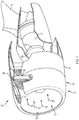
- FIG. 3 illustrates a turbofan engine 300 comprising a nacelle 302 having an inner surface (fan sleeve 304) and an outer surface (external nacelle 306); a core exhaust nozzle 308; a plug 310; and a pylon 312 for attaching the turbofan engine to a wing.
- the nacelle forming a tight wrap (solid line in FIG. 3 ) about the engine core reduces aerodynamic drag and increases net thrust of the turbofan engine.
- less turbine stages are needed and the engine can be made shorter.
- the nacelle exterior must aggressively close out in order to maintain the tight wrap about the engine (and because the turbine diameter is small relative to the fan diameter).
- Using an optimal axisymmetric nozzle together with the aggressive close out (dashed line in FIG. 3 ) of the nacelle exterior can cause undesirable flow separation (turbulence) of air flowing about the engine as well as an increase in nacelle drag. Therefore, for shorter turbofan engines with large diameter fan (e.g., ultra high bypass engines such as, but not limited to, geared fan engines), a nacelle with a benign boat-tail provides optimal drag levels.
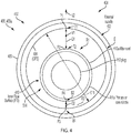
- FIGs. 4 and 5 illustrate an exhaust 400 (e.g., comprising fan nozzle 400a) for a nacelle 402 that overcomes the problems described above.
- the exhaust 400 comprises an outer sleeve 404 including an outer flow surface (OFS) 406 of the fan duct 514 and an outer surface 408 of the nacelle 402.
- FIG. 4 further illustrates an inner flow surface (IFS) 410 of the fan duct 514.
- IFS inner flow surface
- IFS inner flow surface
- IFS inner flow surface
- IFS inner flow surface
- IFS includes a surface of an aft cowl 410a comprising a fairing for the core nozzle 411a.
- An aft/aftmost section or exit station of the OFS 406 includes a curved portion 502 (e.g., bend) so that a first distance D1 between a top T1 of the OFS 406 and a top T2 of the IFS 410 is larger or longer than a second distance D2 between a bottom B1 of the OFS 406 and a bottom B2 of the IFS 410.
- the first distance D1 is in a first region R1 between the pylon and the core exhaust 411 and the second distance D2 is in a second region R2 between the core exhaust 411 (comprising core nozzle 411a) and a section S6 of the outer surface facing away from the aircraft 900a, 900b (referring also to FIG. 9A and 9B ).
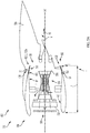
- FIG. 5A is a side view of a turbofan engine 500 including the nacelle 402 comprising the exhaust 400 and an inlet 504.
- An engine core 506 is housed in the nacelle 402, the engine core 506 comprising or connected to the core exhaust 411; and the aft cowl 410a forms a fairing around the core exhaust 411.
- a fan 508 is housed in the nacelle so as to draw a first portion of air 510 through the inlet 504 into the engine core 506 and draw a second portion the air 512 through the inlet 504 into a fan duct 514 between the engine core 506 and the nacelle 402.
- the nacelle 402 forms an outer wall W1 (comprising outer flow surface OFS) of the fan duct 514; and a casing 554 of the engine core 506 and an aft cowl 410a form an inner wall W2 (comprising inner flow surface IFS) of the fan duct 514, so that the OFS 406 and the IFS 410 bound the flow F of the second portion of the air 512.
- the curved portion 502 is illustrated as the solid line in FIG. 5A (the dashed line represents the exhaust without the bend).
- the first portion of air 510 is used to burn fuel in the engine core 506 so as to form exhaust gas (primary flow) exhausted through the core exhaust 411 and generating a first component of engine thrust.
- the primary flow is bounded by the inner side of the aft cowl (extension of the IFS) and the plug.
- the second portion of air 512 is exhausted through the exhaust 400 and generates a second component of engine thrust.
- pylon 516 attached to a first section S5 of the outer surface 408, wherein the pylon 516 is for attaching the nacelle 402 to a wing.
- Pylon 516 includes an aerodynamic surface or fairing covering the pylon 516 and can be attached to the fan case (in which case the fairing extends towards the inlet 504 as illustrated) or the engine core.
- the curved portion 502 comprising the bend or shear is illustrated as the solid line in FIG. 5A (the dashed line represents the exhaust without the curved portion).
- FIG. 5B is a side view illustrating a direct drive turbofan engine 500a (solid line) and a geared turbofan engine 500b (dotted line) comprising the OFS 406 having a curved portion 502, the IFS 410, and aft cowl 410a comprising an extension of the IFS 410 surface beyond the aft station of the OFS 406.
- the aft cowl serves as the outer cover for the primary nozzle (e.g., core nozzle 411a).
- the geared turbofan engine 500b is shorter with fewer engine stages, and also has a smaller engine core, as compared to the direct drive turbofan engine 500a.
- the external nacelle 552 for the geared turbofan engine 500b must close out faster, and to a smaller engine core, resulting in a steeper boat-tail 570 closeout that presents the risk of increased drag due to flow separation.
- FIG. 5C shows that the engine core section surfaces 572 can be made larger in order to compensate for the increased drag of the steeper boat tail 570.
- Using an OFS 406 having a curved portion 502 as described herein overcomes this problem and enables an external nacelle 552 having steeper boat-tail 570b that maintains a tight wrap while at the same time decreasing or mitigating drag due to flow separation.
- the curved portion enables an external nacelle 552 having a steeper boat tail 570b and tighter wrap around the engine core 506 as compared to the boat-tail 570 and wrap of an external nacelle without the curved portion 502.
- FIG. 5B and 5C can further amplify the value of a tight wrap enabled by the shorter engine, but with steeper boat-tail curvatures as compared to the shorter engine described above with reference to FIG. 3 .
- FIG. 6A-6B illustrate that the exhaust 400 having a curved portion 502 (e.g., bend or sheared exhaust) toward the pylon 516 maintains thrust efficiency for the turbofan engine 500 and improves thrust vectoring without significant degradation to the fan exhaust flow 702b.
- a curved portion 502 e.g., bend or sheared exhaust
- FIG. 7 illustrates the interaction between the fan exhaust flow 800 exiting external nacelle 306 and the primary flow comprising core exhaust flow 802 exiting the core exhaust nozzle 308 for a turbofan engine 300 having a nacelle 302 without the curved portion 502 (having upward bend with curvature C) and with a tighter wrap (as illustrated by solid lines in FIG. 3 ).
- the fan exhaust flow 800 and the core exhaust flow 802 interact so as to form a shear layer that produces an acoustic signature typical of nozzle-jet noise.
- the pylon causes interference (deflection 850) of the fan exhaust flow 800 away (e.g. downwards) from the pylon
- a conventional solution would be to increase area A of the fan duct below the core exhaust 308 and furthest from the pylon 312 to redistribute flow away from the pylon, thereby reducing the turning tendencies. Indeed, this can work but the present disclosure has found this is not highly sensitive. Shearing or turning the fan nozzle sleeve (and OFS) upwards or towards the pylon, as described herein (and reducing fan duct area A below the pylon) would seem contrary, putting more fan exhaust flow 800 over the pylon that would then be expected to be deflected downwards.
- FIG. 8 shows the curved portion 502 comprising upward bend having curvature C shifts the fan exhaust flow 702b so that the fan exhaust flow 702b now propagates more in line with the engine's longitudinal axis AA', just like the primary flow (core exhaust flow 702a).
- the curved portion 502 comprising bend or curvature C may apply a vector shift V to the exhaust gas 702 that increases alignment of the thrust vector V3 and/or flow F2 in an aft direction parallel to a longitudinal axis AA of the turbofan engine 500 and/or flight direction of the aircraft.
- Reduced mixing or interaction of the fan exhaust flow 702b and core exhaust flow 702a may reduce noise downstream of the fan nozzle 400a.
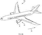
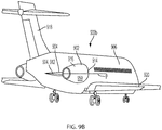
- the exhaust 400 (e.g. sheared exhaust) is not limited to applications on a turbofan engine 500 on a wing 920 as illustrated in FIG. 9A .
- FIG. 9B illustrates an example of an aircraft 900b including an engine 902 including nacelle 916 mounted using pylon 904 to the fuselage 906.
- the engine 902 includes the exhaust 400 having a curved portion 502 as illustrated in FIG. 10A or FIG. 10B .
- FIG. 10A illustrates an exhaust 1000 for a nacelle 916, 402, comprising a nozzle 1002 having a first curved surface 1008 curving away from a longitudinal axis AA' of the nacelle 916, 402 on a first side 1010 of the nozzle 1002 closer to a pylon 904 attached to the nacelle 916; and a second curved surface 1012 curving towards the longitudinal axis AA' on a second side 1014 opposite the first side 1010.
- the first curved surface 1008 has a first radius of curvature C1
- the second curved surface 1012 has a second radius of curvature C2
- the first radius of curvature C1 and the second radius of curvature C2 both lie in a plane P forming a cross section through the nozzle 1002 and a pylon 904, 516 attached to the nacelle 402, 916, and the first radius of curvature C1 is larger than the second radius of curvature C2.
- FIG. 10B illustrates the nozzle 1002 (e.g., fan nozzle or thrust reverser sleeve) including a curved portion 502 so that when the nozzle 1002 is disposed around a body 1016 (e.g., center body or core nozzle), flow F of gas G (e.g., air from a propulsor such as a fan 508 or engine core 506 as illustrated in FIG. 5A and FIG. 8 ) between the nozzle 1002 and the body 1016 is bounded by an OFS 1004 on the nozzle and an IFS 1006 on the body 1016:
- a body 1016 e.g., center body or core nozzle
- G e.g., air from a propulsor such as a fan 508 or engine core 506 as illustrated in FIG. 5A and FIG. 8
- a plane P5 perpendicular to the plane P defines the first side 1010 closer to the pylon 516, 904 on one side of the plane P5 and the second side 1014 on the opposite side of the plane P5 facing away from the aircraft 900a, 900b.
- the curved portion 502 shift the exhaust gas 702 outputted from the nozzle 1002 in a direction V (see FIG 5 and FIG. 8 ) counteracting deflection 854 of the exhaust gas 702 (or exhaust 702f of gas G) away from the pylon 516, the deflection 854 caused by the pylon 516 during flight and/or take-off of the aircraft 900a, 900b propelled using the nozzle 1002.
- the curved portion 502 (first curved surface 1008 and/or the second curved surface 1012) can shift the exhaust gas so as to increase alignment of flow F2 of the exhaust gas 702 from the nozzle in an aft direction 854a parallel to a flight direction 854b of the aircraft and/or the longitudinal axis AA' of an engine 500 comprising the nozzle 1002.
- noise e.g., community noise
- noise experienced downstream of the nozzle 1002 may be reduced and/or the fuel consumed in the engine core 506 connected to the core nozzle 411a may be decreased.
- the first curved surface 1008 and the second curved surface 1012 may both shift a trailing edge E of the nozzle 1002 by 1%-2% of a diameter 518 of the nozzle as measured at the trailing edge and/or the first curved surface and the second curved surface may be within a last 25% of a length of the external nacelle.
- the radius R3 of the nozzle 1002 at the trailing edge E of the nozzle 1002 can vary around the circumference of the nozzle 1002.
- the cross-section at the trailing edge E can have a variety of shapes (e.g., circular, elliptical, or other shapes). Also shown in FIGs. 10A and 10B are shear directions S3 and S4.
- the pylon 904 turns some of the exhaust flow sideways.
- the sideways exhaust flow is not providing lift and creates useless side thrust that must be counteracted by the engine on the other side or aircraft flight controls.
- the exhaust gas 702 can be pointed in the direction 854b of flight so as to improve airplane efficiency.
- the exhausts 400, 1000 illustrated herein comprise a curved portion 502 having a curvature that shifts flow F2 (e.g., fan exhaust flow 702b) of gas G exiting through the exhaust 400 in a direction V6 that counteracts displacement 854 and/or interruption I or interference I2 of the flow F2 by a structure 912 (e.g., pylon 904, wing 920, fuselage 906) attached to the nacelle 402 so as to better align the flow F2 with the direction 854b of flight and/or the longitudinal axis AA' of the engine 500 and/avoid interference I2 of the flow F2 with the aircraft 900a, 900b.
- flow F2 e.g., fan exhaust flow 702b
- a structure 912 e.g., pylon 904, wing 920, fuselage 906
- the nozzles of FIG. 10A and 10B can be implemented in nacelles housing a variety of engines and positioned in a variety of locations on the aircraft.
- the portion of the exhaust deflected downwards by the pylon contributes to the lift, albeit less efficient than the wing (a wing produces lift most efficiently).
- power setting of the engine must be increased to recover thrust needed to maintain flight speed.
- a curved exhaust 400 as described herein to produce vector alignment of the thrust and point the exhaust effectively in the direction 854b of flight (and let the wing do the lifting) configures the aircraft for increased (e.g., maximum) efficiency (e.g., at least 0.25 % improvement in efficiency).
- the optimal vector shift V of the exhaust caused by curved portion 502 may be so that the resultant thrust vector V3 (sum of V and deflection 854 caused by pylon 516) is substantially in the direction 854b of flight.
- the structure 912 may be a pylon 904 and the curved portion 502 having curvature C may shift flow F2 of gas G exiting the exhaust 400 away from the pylon 904 so as to avoid interference I of the flow F2 with the aircraft 900b.
- the curved portion 502 may shift a plume P7 comprising the gas G upwards to counter: (1) deflection 854 of the plume P7 downwards from a direction 854b of flight of the aircraft 900a, 900b, the deflection 854 due to an incidence 960 of the wing relative to the direction 854b of flight, and/or (2) the structure 912 comprising a pylon 904, 516 deflecting or causing the deflection 854 the plume P7 away from the direction 854b of flight.
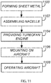
- FIG. 11 is a flowchart illustrating a method of making a nacelle 402 for housing an engine 902, and operating an aircraft 900a, 900b with the engine 902 (referring also to FIG. 4 , FIG. 5A-5C , FIG. 7 , FIGs. 8A-8B , FIG. 9A , 9B , FIG. 10A, and FIG. 10B ).
- Block 1100 represents forming an exhaust 400.
- the nacelle's 402, 916 exhaust 400 may include a curved portion 502 and a nozzle 1002 so that, when the nozzle 1002 is disposed around a body (e.g., core exhaust 411 or core nozzle 411a, e.g., as found in a turbofan engine 500, 902) and flow F of the gas G between the nozzle and the body is bounded by an OFS on the exhaust 400 and an IFS on the body 1006:
- a body e.g., core exhaust 411 or core nozzle 411a, e.g., as found in a turbofan engine 500, 902
- the first point P1, the second point P2, the third point P3, and the fourth point are collinear; P2 is between P4 and P1; P4 is between P2 and P3; and the curved portion is curved (e.g., outward) in a direction having a vector V2 component collinear with a vector V1 from P2 to P1.
- the bend or curved portion 502 may include a first shift S1 in a position of the first point P1 by approximately 1.5 % (e.g., 1-2%) of a diameter 518 of the exhaust 400 (e.g., 1.5%-2.5% or 1%-2% of the diameter 518), as measured at the trailing edge E of the exhaust 400, and a second shift S2 in a position of the third point P3 by approximately 1.5% (e.g., 1-2%) of the diameter 518 of the exhaust 400 (e.g., 0.5%-1.5% of the diameter 518), as measured at the trailing edge E of the exhaust 400.
- the first shift and the second shift may be relative to the positions of the first point P1 and the third point P3, respectively, in a case where the exhaust 400 and the core exhaust 411 are concentric or the first distance D1 is equal to the second distance D2.
- D1 may be 1-2% longer and D2 may be 1-2% shorter relative to what D1 and D2 would have been had the core nozzle been centered on the engine's longitudinal axis AA' or center line.
- bend or curved portion 502 includes a bend (e.g., upward bend 502a) in the direction of the pylon so that the first distance D1 is between the first point P1 at a top T1 of the OFS 406 and the second point P2 at a top T2 of the IFS 410 or core exhaust 411, and the second distance D2 is between the third point P3 at a bottom B1 of the OFS 406 and the fourth point P4 at a bottom B2 of the IFS 410.
- a bend e.g., upward bend 502a
- the curved portion 502 may include a first shift S1 upwards or outwards of the top T1 of the OFS 406, wherein the first shift S1 is approximately 1.5 % (e.g,. 1-2%) of a diameter 518 of the exhaust 400, as measured at the trailing edge E of the exhaust 400, a second shift S2 upwards of the bottom B1 of the OFS 406, wherein the second shift S2 is approximately 1.5% (e.g,. 1-2%) of the diameter 518 of the exhaust 400, as measured at the trailing edge E of the exhaust 400.
- the first shift S1 and the second shift S2 may be measured as compared to the positions P1-P4 when the exhaust 400 and the core exhaust 506 are concentric (dashed line in FIG. 5A ).
- the bend or curved portion 502 counteracts or neutralizes a pressure field PF created by the pylon, the pressure field PF deflecting the thrust vector V3 of the thrust 812, and the bend or curved portion 502 increases alignment of the thrust vector V3 in an aft direction parallel to a longitudinal axis AA' of the turbofan engine 500, 902.
- the exhaust 400 may comprise a shear forming the bend or curved portion 502 (e.g., the exhaust 400 comprises a shear S3, S4 in a plane P forming a cross section through the pylon 516, 904 and the exhaust 400 and the shear forms the curved portion 502).
- the forming comprises shearing a metal tube 550 so as to form a sheared tube 550a including the bend or curved portion 502.
- the forming may comprise forming sheet metal into the exhaust 400, so that the OFS 406 includes the bend or curved portion 502 (e.g., forming shifts S1 and S2 that are 1-2% of the exhaust's diameter 518).
- the bend or curved portion 502 in the exhaust 400 allows better performing, smaller radius exhaust center-bodies to be utilized, thereby increasing thrust 812 outputted from the exhaust 400 for a given fuel consumption.
- the fan duct outer wall comprising the fan nozzle 400a and including the curved portion 502 may comprise a composite structure.
- Block 1102 represents optionally assembling the exhaust 400 with an inlet 504 so as to form a nacelle 402.
- the nacelle 402 may further include a fan cowl and thrust reversers.
- the nacelle 402 may be configured to include the inlet 504 and the exhaust 400.
- the bend or curved portion 502 of the nacelle 402 including the bend or curved portion 502 may be in a rear half H of the fan nozzle 400a.
- the nacelle comprises an external nacelle 552 and the curved portion is entirely within the last 25% of the length L1 of the external nacelle (referring to FIG. 5A ).
- a radius R3 (half of diameter 518) of the exhaust 400 at the trailing edge E of the exhaust 400 of the nacelle 402 including the bend or curved portion 502 is smaller as compared to the nacelle 302 without the bend or curved portion 502.
- Block 1104 represents providing an engine 902 (e.g., turbofan engine 500) including an engine core 506 housed in the nacelle 402, the engine core 506 comprising or connected to a core nozzle 411a; a fan 508 housed in the nacelle 402 so as to draw a first portion of air 510 through the inlet 504 into the engine core 506 and draw a second portion the air 512 through the inlet 504 into a fan duct 514 between the engine core 506 and the nacelle 402.
- the fan duct has an OFS 406 on the nacelle and an IFS 410 opposite the OFS, so that the OFS 406 and the IFS 410 bound the flow F of the second portion of the air 512.
- the first portion of air 510 is used to burn fuel in the engine core 506 so as to form first exhaust gases 702d exhausted through the core exhaust 411 (e.g., nozzle 411a) and generating a first component of thrust 812.
- the second portion of air 512 is exhausted as second exhaust gases 702e through the exhaust 400 of the nacelle 402 so as to generate a second component of thrust 812.
- the curved portion 502 shifts the second exhaust gases (or applies a vector shift V to the second exhaust gases) in a direction so as to counteract deflection of the second exhaust gases 702e caused by the pylon 516 during flight and/or take-off of the aircraft 900a.
- the outer flow surface 406 includes a curved portion 502 having a curvature C such that a first distance D1 between a first point P1 at a trailing edge E on the outer flow surface 406 and a second point P2 on the inner flow surface 410 is larger than a second distance D2 between a third point P3 on the trailing edge E of the outer flow surface 406 and a fourth point P4 on the inner flow surface 410; the first distance D1 is in a first region R1 between the pylon 516 and the core exhaust 411; the second distance D2 is in a second region R2 between the core exhaust 411 and a section S5 of the nacelle 402 facing away from an aircraft 900a propelled using the engine 500.
- the bend or curved portion 502 of the OFS 406 may be such that, at a given thrust 812 generated by the engine 902 (e.g., turbofan engine 500), noise experienced downstream of the engine 902 is reduced and/or the fuel consumed in the engine core 506 is decreased.
- the vector shift V may improve aircraft fuel efficiency on the order of 0.5% (e.g., by 0.5% or at least 0.5%).
- the turbofan engine 500, 902 can include the bend or curved portion 502, wherein the bend or curved portion 502 increases alignment of a thrust vector V3 of the thrust 812 in an aft direction parallel to a longitudinal axis AA of the turbofan engine 500, 902.
- the engine comprises a geared turbofan engine and the nacelle 402 forms a tighter wrap around the engine core 506 as compared to the nacelle 302 without the curved portion, thereby reducing aerodynamic drag of the engine 500, 902.
- Block 1106 represents mounting one or more of the engines 902 (e.g., turbofan engines 500) on an aircraft 900a, 900b using the pylon 904, 516 using a structure 912.
- the engines 902 e.g., turbofan engines 500
- the structure 912 may be a mount comprising a pylon 516 attaching the nacelle 400 to a wing 920.
- the structure 912 is a pylon 904 attached to the nacelle 400 and attaching the nacelle 400 to a fuselage 906 or an empennage 918.
- the nacelle including the curvature C or curved portion 502 can also be used to house any engine (e.g., propeller engine or rocket engine) whose output thrust may be deflected by the pylon attaching the nacelle to the aircraft.
- any engine e.g., propeller engine or rocket engine
- Block 1108 represents optionally operating an aircraft powered by the engine 902.
- the curvature C or curved portion 502 (e.g., shear) better aligns the fan exhaust flow 702b with the longitudinal axis AA of the engine 500 and/or flight direction 854b.
- Shear e.g., curvature C or curved portion 502
- the curvature C or curved portion 502 may apply a vector shift V3 to the second exhaust gases in a direction so as to counteract deflection of the second exhaust gases caused by the pylon during flight and/or take-off of the aircraft (e.g., neutralizing the pressure field downstream of the fan nozzle, thereby allowing the fan flow to propagate aft along the engine axis, with a collateral benefit of (in one or more examples) less mixing with the primary exhaust and providing jet noise reduction.
- the upward bend or curved portion 502 may reduce noise experienced downstream of the turbofan engine and/or may decrease fuel consumed in the engine core.
- the bend or curved portion 502 in the fan nozzle 400a may reduce fuel burn by 0.25%-0.75% (e.g., when D1 and D2 change by +2.54 cm (+1 inch) and -2.54 cm (-1 inch) respectively).
- the bend or curved portion 502 may also alleviate adverse pressure on the crown line of the nacelle.
- the curvature C or curved portion can be configured to deflect or vector fan exhaust flow 702b toward the aircraft 900a, 900b (for instance, to compensate for wing upwash) so as to increase alignment of the fan exhaust flow with the direction of flight.
- curvature C or curved portion 502 can be configured to deflect or vector the fan exhaust flow away from the pylon to avoid interference with the airplane.
- nacelle 402 can solve drag problems caused using a tighter wrap with short propulsion systems (e.g., geared turbofans), nozzle performance improvements in thrust efficiency and thrust vectoring, as well as acoustic benefits, have also been observed in long (non-geared turbofan) engines and may also be applicable to all types of engines generally.
- short propulsion systems e.g., geared turbofans
- nozzle performance improvements in thrust efficiency and thrust vectoring, as well as acoustic benefits have also been observed in long (non-geared turbofan) engines and may also be applicable to all types of engines generally.
Landscapes
- Engineering & Computer Science (AREA)
- Chemical & Material Sciences (AREA)
- Combustion & Propulsion (AREA)
- Mechanical Engineering (AREA)
- General Engineering & Computer Science (AREA)
- Aviation & Aerospace Engineering (AREA)
- Structures Of Non-Positive Displacement Pumps (AREA)
- Exhaust Silencers (AREA)
Claims (15)
- Nacelle (302, 402, 916), comprenant un échappement (400, 1000) et un mât (312, 516, 904), l'échappement (400, 1000) comprenant une tuyère (1002, 411a), la tuyère (1002, 411a) comportant une partie incurvée (502) conçue pour déplacer l'écoulement de gaz sortant par l'échappement (400, 1000) dans une direction (854b) qui contrebalance la déflexion (854) de l'écoulement par le mât fixé à la nacelle (302, 402, 916), dans laquelle :la tuyère (1002, 411a) est disposée autour d'un corps (1016) et l'écoulement de gaz existant entre la tuyère (1002, 411a) et le corps (1016) est délimité par une surface d'écoulement extérieure (1004) de la tuyère (1002, 411a) et une surface d'écoulement intérieure (1006) du corps (1016) ;une première distance D1 existant entre un premier point P1 de la surface d'écoulement extérieure (1004) et un deuxième point P2 de la surface d'écoulement intérieure (1006) est plus longue qu'une deuxième distance D2 existant entre un troisième point P3 de la surface d'écoulement extérieure (1004) et un quatrième point P4 du corps (1016) ;le mât (312, 516, 904) fixé à la nacelle (302, 402, 916) est plus proche du premier point P1 que du troisième point P3 ; etl'échappement des gaz (702) émis par la tuyère (1002, 411a) est déplacé dans la direction (V) contrebalançant la déflexion (854) des gaz (702) s'éloignant du mât (312, 516, 904) et causée par le mât (312, 516, 904) pendant le vol et/ou le décollage d'un aéronef (900a, 900b) propulsé au moyen de la tuyère (1002, 411a).
- Nacelle (302, 402, 916) selon la revendication 1, dans laquelle le mât (312, 516, 904) est conçu pour fixer la nacelle (302, 402, 916) à une aile (920).
- Nacelle (302, 402, 916) selon la revendication 1 ou 2, dans laquelle le mât (312, 516, 904) est conçu pour fixer la nacelle (302, 402, 916) à un fuselage (906) ou à un empennage (918).
- Nacelle (302, 402, 916) selon l'une quelconque des revendications 1 à 3, dans laquelle la partie incurvée (502) :
est conçue pour accroître l'alignement de l'écoulement F2 des gaz d'échappement (702) vers l'arrière (854a) parallèlement à un axe longitudinal AA d'un réacteur (500, 902) comprenant la tuyère (1002, 411a). - Nacelle (302, 402, 916) selon l'une quelconque des revendications 1 à 4, dans laquelle la tuyère (1002, 411a) est conçue sous la forme d'une tuyère de soufflante (410a) dans un turboréacteur à double flux (902) et la partie incurvée (502) comporte :un premier déplacement S1, concernant la position du premier point P1, de 1 à 2 % du diamètre (518) de la tuyère (1002, 411a), mesuré au niveau du bord de fuite E de la tuyère (1002, 411a), etun deuxième déplacement S2, concernant la position du troisième point P3, de 1 à 2 % du diamètre (518) de la tuyère (1002, 411a), mesuré au niveau du bord de fuite E de la tuyère de soufflante (410a).
- Nacelle (302, 402, 916) selon la revendication 1, dans laquelle la partie incurvée (502) présente une courbure C conçue pour déplacer l'écoulement F2 des gaz sortant de l'échappement (400, 1000) en l'éloignant du mât (312, 516, 904) de façon à éviter une interférence de l'écoulement avec un aéronef (900a, 900b) comprenant la nacelle (302, 402, 916).
- Nacelle (302, 402, 916) selon l'une quelconque des revendications 1 à 6, dans laquelle, lorsque la nacelle (302, 402, 916) est fixée à un aéronef (900a, 900b) comprenant une aile (920), la partie incurvée (502) est conçue pour déplacer un jet d'échappement P7 comprenant les gaz G vers le haut afin de contrer :une déflexion (854) du jet d'échappement P7 vers le bas à partir d'une direction (854b) de vol de l'aéronef (900a, 900b), la déflexion (854) étant due à une incidence (960) de l'aile (920) par rapport à la direction (854b) du vol, et/ouune déflexion, par le mât (312, 516, 904), du jet d'échappement P7, qui s'éloigne de la direction (854b) du vol.
- Nacelle (302, 402, 916) selon la revendication 1, dans laquelle :la tuyère (1002, 411a) comporte une première surface incurvée (1008) dont la courbure va en s'éloignant d'un axe longitudinal de la nacelle (302, 402, 916) sur un premier côté (1010) de la tuyère (1002, 411a), et une deuxième surface incurvée (1012) dont la courbure va en se rapprochant de l'axe longitudinal sur un deuxième côté (1014) opposé au premier côté (1010),étant entendu que :la première surface incurvée (1008) présente un premier rayon de courbure C1,la deuxième surface incurvée (1012) présente un deuxième rayon de courbure C2,le premier rayon de courbure C1 et le deuxième rayon de courbure C2 se situent tous deux dans un plan P coupant la tuyère (1002, 411a) et un mât (312, 516, 904) fixé à la nacelle (302, 402, 916),le premier rayon de courbure C1 est supérieur au deuxième rayon de courbure C2, et le premier côté (1010) est sur un côté du plan P qui est plus proche du mât (312, 516, 904) fixé à la tuyère (1002, 411a).
- Nacelle (302, 402, 916) selon la revendication 8, dans laquelle :
la première surface incurvée (1008) et la deuxième surface incurvée (1012) sont toutes deux conçues pour déplacer un bord de fuite E de la tuyère (1002, 411a) de 1 à 2 % du diamètre (518) de la tuyère (1002, 411a), mesuré au niveau du bord de fuite E. - Nacelle (302, 402, 916) selon la revendication 8 ou 9, dans laquelle la première surface incurvée (1008) et la deuxième surface incurvée (1012) se trouvent dans une moitié arrière de la tuyère (1002, 411a).
- Nacelle (302, 402, 916) selon l'une quelconque des revendications 8 à 10, ladite nacelle (302, 402, 916) comprenant une nacelle externe (552), et dans laquelle la première surface incurvée (1008) et la deuxième surface incurvée (1012) se trouvent dans les 25 % terminaux d'une longueur de la nacelle externe (552).
- Nacelle (302, 402, 916) selon l'une quelconque des revendications 8 à 11, dans laquelle la première surface incurvée (1008) et/ou la deuxième surface incurvée (1012) sont conçues pour déplacer les gaz d'échappement (702) émis par la tuyère (1002, 411a) dans une direction (854b) contrebalançant la déflexion (854) des gaz d'échappement (702) causée par le mât (312, 516, 904) pendant le vol et/ou le décollage d'un aéronef (900a, 900b) propulsé par la tuyère (1002, 411a), de façon à accroître l'alignement de l'écoulement F2 des gaz d'échappement (702) de la tuyère (1002, 411a) vers l'arrière (854a) parallèlement à un axe longitudinal AA d'un réacteur (500, 902) comprenant la nacelle (302, 402, 916).
- Nacelle (302, 402, 916) selon l'une quelconque des revendications 8 à 12, dans laquelle le mât (312, 516, 904) est conçu pour fixer la nacelle (302, 402, 916) à une aile (920).
- Nacelle (302, 402, 916) selon l'une quelconque des revendications 8 à 13, dans laquelle le mât (312, 516, 904) est conçu pour fixer la nacelle (302, 402, 916) à un fuselage (906) ou à un empennage (918).
- Réacteur (500, 902) comprenant une nacelle (302, 402, 916) selon l'une quelconque des revendications précédentes.
Applications Claiming Priority (1)
| Application Number | Priority Date | Filing Date | Title |
|---|---|---|---|
| US16/248,342 US11306681B2 (en) | 2019-01-15 | 2019-01-15 | Sheared exhaust nozzle |
Publications (2)
| Publication Number | Publication Date |
|---|---|
| EP3683151A1 EP3683151A1 (fr) | 2020-07-22 |
| EP3683151B1 true EP3683151B1 (fr) | 2021-11-03 |
Family
ID=69411152
Family Applications (1)
| Application Number | Title | Priority Date | Filing Date |
|---|---|---|---|
| EP19218672.4A Active EP3683151B1 (fr) | 2019-01-15 | 2019-12-20 | Nacelle |
Country Status (3)
| Country | Link |
|---|---|
| US (2) | US11306681B2 (fr) |
| EP (1) | EP3683151B1 (fr) |
| CN (1) | CN111434910B (fr) |
Family Cites Families (20)
| Publication number | Priority date | Publication date | Assignee | Title |
|---|---|---|---|---|
| FR911269A (fr) | 1945-06-05 | 1946-07-03 | Système de propulsion des mobiles utilisant un jet de gaz sur des surfaces | |
| US3658279A (en) | 1970-04-21 | 1972-04-25 | Lockheed Aircraft Corp | Integrated propulsion system |
| US4066214A (en) | 1976-10-14 | 1978-01-03 | The Boeing Company | Gas turbine exhaust nozzle for controlled temperature flow across adjoining airfoils |
| US4280587A (en) | 1979-05-08 | 1981-07-28 | The Boeing Company | Noise-suppressing jet engine nozzles and method |
| FR2501786A1 (fr) | 1981-03-13 | 1982-09-17 | Snecma | Dispositif de roulement et de guidage d'une tuyere orientable de propulseur a reaction |
| GB2356897B (en) | 1999-12-01 | 2003-05-14 | Secr Defence | Improved nozzle |
| US6532729B2 (en) * | 2001-05-31 | 2003-03-18 | General Electric Company | Shelf truncated chevron exhaust nozzle for reduction of exhaust noise and infrared (IR) signature |
| DE602005005157T2 (de) | 2005-02-11 | 2009-03-19 | Rolls-Royce Plc | Triebwerkanordnung |
| US7509797B2 (en) * | 2005-04-29 | 2009-03-31 | General Electric Company | Thrust vectoring missile turbojet |
| FR2900906B1 (fr) * | 2006-05-09 | 2009-01-09 | Airbus France Sas | Systeme de fixation tolerant aux dommages pour moteur d'aeronef |
| US7900433B2 (en) * | 2006-08-31 | 2011-03-08 | United Technologies Corporation | Fan exhaust nozzle for turbofan engine |
| EP2074301B1 (fr) * | 2006-10-12 | 2016-02-24 | United Technologies Corporation | Turboréacteur à double-flux avec une tuyère de poussée controlée pour décollage et atterrissage |
| US8127529B2 (en) * | 2007-03-29 | 2012-03-06 | United Technologies Corporation | Variable area fan nozzle and thrust reverser |
| CN104040158A (zh) * | 2011-12-08 | 2014-09-10 | 联合工艺公司 | 具有轴向可移动风扇可变面积喷嘴的燃气涡轮发动机 |
| US9085995B2 (en) * | 2012-04-18 | 2015-07-21 | Hamilton Sundstrand Corporation | Anti-vortex shedding generator for APU support |
| CN105464838B (zh) * | 2014-09-25 | 2019-05-21 | 波音公司 | 用于被动推力导向和羽流偏转的方法和装置 |
| EP3009345A1 (fr) * | 2014-10-14 | 2016-04-20 | Airbus Operations GmbH | Aéronef |
| US10700295B2 (en) * | 2015-09-14 | 2020-06-30 | Uea Enterprises Limited | Metal complexes |
| US10961950B2 (en) * | 2016-11-03 | 2021-03-30 | The Boeing Company | Fan nacelle trailing edge |
| CN208310917U (zh) | 2018-03-19 | 2019-01-01 | 西北工业大学 | 一种解决s弯喷管与涡扇发动机匹配问题的转接段结构 |
-
2019
- 2019-01-15 US US16/248,342 patent/US11306681B2/en active Active
- 2019-12-20 EP EP19218672.4A patent/EP3683151B1/fr active Active
-
2020
- 2020-01-14 CN CN202010037606.8A patent/CN111434910B/zh active Active
-
2022
- 2022-03-15 US US17/695,560 patent/US20220205409A1/en active Pending
Also Published As
| Publication number | Publication date |
|---|---|
| CN111434910A (zh) | 2020-07-21 |
| CN111434910B (zh) | 2024-03-15 |
| EP3683151A1 (fr) | 2020-07-22 |
| US11306681B2 (en) | 2022-04-19 |
| US20220205409A1 (en) | 2022-06-30 |
| US20200224605A1 (en) | 2020-07-16 |
Similar Documents
| Publication | Publication Date | Title |
|---|---|---|
| US7665689B2 (en) | Unconventional integrated propulsion systems and methods for blended wing body aircraft | |
| EP1895140B1 (fr) | Buse d'échappement de Soufflante pour turboréacteur à double flux | |
| US7850116B2 (en) | Ducted open rotor apparatus and method | |
| US7726609B2 (en) | High-performance low-noise aircraft exhaust systems and methods | |
| EP2685065B1 (fr) | Turbopropulseur | |
| US10967980B2 (en) | Turbine engine propelled airplane having an acoustic baffle | |
| US20020096598A1 (en) | Integrated and/or modular high-speed aircraft | |
| US20090084889A1 (en) | Aircraft having a reduced acoustic signature | |
| US9732700B2 (en) | Methods and apparatus for passive thrust vectoring and plume deflection | |
| US20140290270A1 (en) | Attachment pylon for a turbine engine | |
| EP3323730B1 (fr) | Avion comportant un turbopropulseur à montage incliné | |
| US20100313545A1 (en) | Gas turbine engine nozzle configurations | |
| US20100254803A1 (en) | Turbofan engine noise suppression using fan flow deflector | |
| EP3306067B1 (fr) | Système et procédé de réduction de l'impact des gaz d'échappement de turbine sur une structure d'aéronef adjacente | |
| EP2865874B1 (fr) | Turboréacteur avec vectorisation passive de poussée | |
| EP3001019B1 (fr) | Procédés et appareil de vectorisation passive de poussée et déflexion de panache | |
| CA2666190C (fr) | Dispositif de reduction de trainee de nacelle pour un moteur de turbine a gaz a turbo reacteur | |
| EP3683151B1 (fr) | Nacelle | |
| US20190210710A1 (en) | Engine nacelle for an aircraft | |
| US11772779B2 (en) | Propulsion unit with improved boundary layer ingestion | |
| US11920539B1 (en) | Gas turbine exhaust nozzle noise abatement | |
| CN112061404A (zh) | 减轻机舱入口中的不利流条件 | |
| CN114810414A (zh) | 矢量调节喷管和自适应变循环发动机 | |
| Trittler et al. | Optimization Aspects of an Ejector Type Hypersonic Thrust Nozzle |
Legal Events
| Date | Code | Title | Description |
|---|---|---|---|
| PUAI | Public reference made under article 153(3) epc to a published international application that has entered the european phase |
Free format text: ORIGINAL CODE: 0009012 |
|
| STAA | Information on the status of an ep patent application or granted ep patent |
Free format text: STATUS: THE APPLICATION HAS BEEN PUBLISHED |
|
| AK | Designated contracting states |
Kind code of ref document: A1 Designated state(s): AL AT BE BG CH CY CZ DE DK EE ES FI FR GB GR HR HU IE IS IT LI LT LU LV MC MK MT NL NO PL PT RO RS SE SI SK SM TR |
|
| AX | Request for extension of the european patent |
Extension state: BA ME |
|
| STAA | Information on the status of an ep patent application or granted ep patent |
Free format text: STATUS: REQUEST FOR EXAMINATION WAS MADE |
|
| 17P | Request for examination filed |
Effective date: 20201229 |
|
| RBV | Designated contracting states (corrected) |
Designated state(s): AL AT BE BG CH CY CZ DE DK EE ES FI FR GB GR HR HU IE IS IT LI LT LU LV MC MK MT NL NO PL PT RO RS SE SI SK SM TR |
|
| GRAP | Despatch of communication of intention to grant a patent |
Free format text: ORIGINAL CODE: EPIDOSNIGR1 |
|
| STAA | Information on the status of an ep patent application or granted ep patent |
Free format text: STATUS: GRANT OF PATENT IS INTENDED |
|
| INTG | Intention to grant announced |
Effective date: 20210225 |
|
| RIN1 | Information on inventor provided before grant (corrected) |
Inventor name: WILLIE, ROBERT H. Inventor name: CERRA, DAVID F. Inventor name: ACHESON, KURT E. |
|
| GRAJ | Information related to disapproval of communication of intention to grant by the applicant or resumption of examination proceedings by the epo deleted |
Free format text: ORIGINAL CODE: EPIDOSDIGR1 |
|
| STAA | Information on the status of an ep patent application or granted ep patent |
Free format text: STATUS: REQUEST FOR EXAMINATION WAS MADE |
|
| GRAP | Despatch of communication of intention to grant a patent |
Free format text: ORIGINAL CODE: EPIDOSNIGR1 |
|
| STAA | Information on the status of an ep patent application or granted ep patent |
Free format text: STATUS: GRANT OF PATENT IS INTENDED |
|
| INTC | Intention to grant announced (deleted) | ||
| INTG | Intention to grant announced |
Effective date: 20210702 |
|
| GRAS | Grant fee paid |
Free format text: ORIGINAL CODE: EPIDOSNIGR3 |
|
| GRAA | (expected) grant |
Free format text: ORIGINAL CODE: 0009210 |
|
| STAA | Information on the status of an ep patent application or granted ep patent |
Free format text: STATUS: THE PATENT HAS BEEN GRANTED |
|
| AK | Designated contracting states |
Kind code of ref document: B1 Designated state(s): AL AT BE BG CH CY CZ DE DK EE ES FI FR GB GR HR HU IE IS IT LI LT LU LV MC MK MT NL NO PL PT RO RS SE SI SK SM TR |
|
| REG | Reference to a national code |
Ref country code: GB Ref legal event code: FG4D |
|
| REG | Reference to a national code |
Ref country code: AT Ref legal event code: REF Ref document number: 1443763 Country of ref document: AT Kind code of ref document: T Effective date: 20211115 Ref country code: CH Ref legal event code: EP |
|
| REG | Reference to a national code |
Ref country code: DE Ref legal event code: R096 Ref document number: 602019008953 Country of ref document: DE |
|
| REG | Reference to a national code |
Ref country code: IE Ref legal event code: FG4D |
|
| REG | Reference to a national code |
Ref country code: LT Ref legal event code: MG9D |
|
| REG | Reference to a national code |
Ref country code: NL Ref legal event code: MP Effective date: 20211103 |
|
| REG | Reference to a national code |
Ref country code: AT Ref legal event code: MK05 Ref document number: 1443763 Country of ref document: AT Kind code of ref document: T Effective date: 20211103 |
|
| PG25 | Lapsed in a contracting state [announced via postgrant information from national office to epo] |
Ref country code: RS Free format text: LAPSE BECAUSE OF FAILURE TO SUBMIT A TRANSLATION OF THE DESCRIPTION OR TO PAY THE FEE WITHIN THE PRESCRIBED TIME-LIMIT Effective date: 20211103 Ref country code: LT Free format text: LAPSE BECAUSE OF FAILURE TO SUBMIT A TRANSLATION OF THE DESCRIPTION OR TO PAY THE FEE WITHIN THE PRESCRIBED TIME-LIMIT Effective date: 20211103 Ref country code: FI Free format text: LAPSE BECAUSE OF FAILURE TO SUBMIT A TRANSLATION OF THE DESCRIPTION OR TO PAY THE FEE WITHIN THE PRESCRIBED TIME-LIMIT Effective date: 20211103 Ref country code: BG Free format text: LAPSE BECAUSE OF FAILURE TO SUBMIT A TRANSLATION OF THE DESCRIPTION OR TO PAY THE FEE WITHIN THE PRESCRIBED TIME-LIMIT Effective date: 20220203 Ref country code: AT Free format text: LAPSE BECAUSE OF FAILURE TO SUBMIT A TRANSLATION OF THE DESCRIPTION OR TO PAY THE FEE WITHIN THE PRESCRIBED TIME-LIMIT Effective date: 20211103 |
|
| PG25 | Lapsed in a contracting state [announced via postgrant information from national office to epo] |
Ref country code: IS Free format text: LAPSE BECAUSE OF FAILURE TO SUBMIT A TRANSLATION OF THE DESCRIPTION OR TO PAY THE FEE WITHIN THE PRESCRIBED TIME-LIMIT Effective date: 20220303 Ref country code: SE Free format text: LAPSE BECAUSE OF FAILURE TO SUBMIT A TRANSLATION OF THE DESCRIPTION OR TO PAY THE FEE WITHIN THE PRESCRIBED TIME-LIMIT Effective date: 20211103 Ref country code: PT Free format text: LAPSE BECAUSE OF FAILURE TO SUBMIT A TRANSLATION OF THE DESCRIPTION OR TO PAY THE FEE WITHIN THE PRESCRIBED TIME-LIMIT Effective date: 20220303 Ref country code: PL Free format text: LAPSE BECAUSE OF FAILURE TO SUBMIT A TRANSLATION OF THE DESCRIPTION OR TO PAY THE FEE WITHIN THE PRESCRIBED TIME-LIMIT Effective date: 20211103 Ref country code: NO Free format text: LAPSE BECAUSE OF FAILURE TO SUBMIT A TRANSLATION OF THE DESCRIPTION OR TO PAY THE FEE WITHIN THE PRESCRIBED TIME-LIMIT Effective date: 20220203 Ref country code: NL Free format text: LAPSE BECAUSE OF FAILURE TO SUBMIT A TRANSLATION OF THE DESCRIPTION OR TO PAY THE FEE WITHIN THE PRESCRIBED TIME-LIMIT Effective date: 20211103 Ref country code: LV Free format text: LAPSE BECAUSE OF FAILURE TO SUBMIT A TRANSLATION OF THE DESCRIPTION OR TO PAY THE FEE WITHIN THE PRESCRIBED TIME-LIMIT Effective date: 20211103 Ref country code: HR Free format text: LAPSE BECAUSE OF FAILURE TO SUBMIT A TRANSLATION OF THE DESCRIPTION OR TO PAY THE FEE WITHIN THE PRESCRIBED TIME-LIMIT Effective date: 20211103 Ref country code: GR Free format text: LAPSE BECAUSE OF FAILURE TO SUBMIT A TRANSLATION OF THE DESCRIPTION OR TO PAY THE FEE WITHIN THE PRESCRIBED TIME-LIMIT Effective date: 20220204 Ref country code: ES Free format text: LAPSE BECAUSE OF FAILURE TO SUBMIT A TRANSLATION OF THE DESCRIPTION OR TO PAY THE FEE WITHIN THE PRESCRIBED TIME-LIMIT Effective date: 20211103 |
|
| PG25 | Lapsed in a contracting state [announced via postgrant information from national office to epo] |
Ref country code: SM Free format text: LAPSE BECAUSE OF FAILURE TO SUBMIT A TRANSLATION OF THE DESCRIPTION OR TO PAY THE FEE WITHIN THE PRESCRIBED TIME-LIMIT Effective date: 20211103 Ref country code: SK Free format text: LAPSE BECAUSE OF FAILURE TO SUBMIT A TRANSLATION OF THE DESCRIPTION OR TO PAY THE FEE WITHIN THE PRESCRIBED TIME-LIMIT Effective date: 20211103 Ref country code: RO Free format text: LAPSE BECAUSE OF FAILURE TO SUBMIT A TRANSLATION OF THE DESCRIPTION OR TO PAY THE FEE WITHIN THE PRESCRIBED TIME-LIMIT Effective date: 20211103 Ref country code: EE Free format text: LAPSE BECAUSE OF FAILURE TO SUBMIT A TRANSLATION OF THE DESCRIPTION OR TO PAY THE FEE WITHIN THE PRESCRIBED TIME-LIMIT Effective date: 20211103 Ref country code: DK Free format text: LAPSE BECAUSE OF FAILURE TO SUBMIT A TRANSLATION OF THE DESCRIPTION OR TO PAY THE FEE WITHIN THE PRESCRIBED TIME-LIMIT Effective date: 20211103 Ref country code: CZ Free format text: LAPSE BECAUSE OF FAILURE TO SUBMIT A TRANSLATION OF THE DESCRIPTION OR TO PAY THE FEE WITHIN THE PRESCRIBED TIME-LIMIT Effective date: 20211103 |
|
| REG | Reference to a national code |
Ref country code: DE Ref legal event code: R097 Ref document number: 602019008953 Country of ref document: DE |
|
| PG25 | Lapsed in a contracting state [announced via postgrant information from national office to epo] |
Ref country code: MC Free format text: LAPSE BECAUSE OF FAILURE TO SUBMIT A TRANSLATION OF THE DESCRIPTION OR TO PAY THE FEE WITHIN THE PRESCRIBED TIME-LIMIT Effective date: 20211103 |
|
| PLBE | No opposition filed within time limit |
Free format text: ORIGINAL CODE: 0009261 |
|
| STAA | Information on the status of an ep patent application or granted ep patent |
Free format text: STATUS: NO OPPOSITION FILED WITHIN TIME LIMIT |
|
| REG | Reference to a national code |
Ref country code: BE Ref legal event code: MM Effective date: 20211231 |
|
| 26N | No opposition filed |
Effective date: 20220804 |
|
| PG25 | Lapsed in a contracting state [announced via postgrant information from national office to epo] |
Ref country code: LU Free format text: LAPSE BECAUSE OF NON-PAYMENT OF DUE FEES Effective date: 20211220 Ref country code: IE Free format text: LAPSE BECAUSE OF NON-PAYMENT OF DUE FEES Effective date: 20211220 Ref country code: AL Free format text: LAPSE BECAUSE OF FAILURE TO SUBMIT A TRANSLATION OF THE DESCRIPTION OR TO PAY THE FEE WITHIN THE PRESCRIBED TIME-LIMIT Effective date: 20211103 |
|
| PG25 | Lapsed in a contracting state [announced via postgrant information from national office to epo] |
Ref country code: SI Free format text: LAPSE BECAUSE OF FAILURE TO SUBMIT A TRANSLATION OF THE DESCRIPTION OR TO PAY THE FEE WITHIN THE PRESCRIBED TIME-LIMIT Effective date: 20211103 Ref country code: BE Free format text: LAPSE BECAUSE OF NON-PAYMENT OF DUE FEES Effective date: 20211231 |
|
| PG25 | Lapsed in a contracting state [announced via postgrant information from national office to epo] |
Ref country code: IT Free format text: LAPSE BECAUSE OF FAILURE TO SUBMIT A TRANSLATION OF THE DESCRIPTION OR TO PAY THE FEE WITHIN THE PRESCRIBED TIME-LIMIT Effective date: 20211103 |
|
| P01 | Opt-out of the competence of the unified patent court (upc) registered |
Effective date: 20230516 |
|
| PG25 | Lapsed in a contracting state [announced via postgrant information from national office to epo] |
Ref country code: CY Free format text: LAPSE BECAUSE OF FAILURE TO SUBMIT A TRANSLATION OF THE DESCRIPTION OR TO PAY THE FEE WITHIN THE PRESCRIBED TIME-LIMIT Effective date: 20211103 |
|
| PG25 | Lapsed in a contracting state [announced via postgrant information from national office to epo] |
Ref country code: HU Free format text: LAPSE BECAUSE OF FAILURE TO SUBMIT A TRANSLATION OF THE DESCRIPTION OR TO PAY THE FEE WITHIN THE PRESCRIBED TIME-LIMIT; INVALID AB INITIO Effective date: 20191220 |
|
| REG | Reference to a national code |
Ref country code: CH Ref legal event code: PL |
|
| PG25 | Lapsed in a contracting state [announced via postgrant information from national office to epo] |
Ref country code: LI Free format text: LAPSE BECAUSE OF NON-PAYMENT OF DUE FEES Effective date: 20221231 Ref country code: CH Free format text: LAPSE BECAUSE OF NON-PAYMENT OF DUE FEES Effective date: 20221231 |
|
| PGFP | Annual fee paid to national office [announced via postgrant information from national office to epo] |
Ref country code: GB Payment date: 20231227 Year of fee payment: 5 |
|
| PGFP | Annual fee paid to national office [announced via postgrant information from national office to epo] |
Ref country code: FR Payment date: 20231227 Year of fee payment: 5 |
|
| PG25 | Lapsed in a contracting state [announced via postgrant information from national office to epo] |
Ref country code: MK Free format text: LAPSE BECAUSE OF FAILURE TO SUBMIT A TRANSLATION OF THE DESCRIPTION OR TO PAY THE FEE WITHIN THE PRESCRIBED TIME-LIMIT Effective date: 20211103 |
|
| PGFP | Annual fee paid to national office [announced via postgrant information from national office to epo] |
Ref country code: DE Payment date: 20231229 Year of fee payment: 5 |