EP3683079B1 - Body frame and automobile having automobile body frame - Google Patents
Body frame and automobile having automobile body frame Download PDFInfo
- Publication number
- EP3683079B1 EP3683079B1 EP18857061.8A EP18857061A EP3683079B1 EP 3683079 B1 EP3683079 B1 EP 3683079B1 EP 18857061 A EP18857061 A EP 18857061A EP 3683079 B1 EP3683079 B1 EP 3683079B1
- Authority
- EP
- European Patent Office
- Prior art keywords
- body frame
- automobile
- automobile body
- battery pack
- present
- Prior art date
- Legal status (The legal status is an assumption and is not a legal conclusion. Google has not performed a legal analysis and makes no representation as to the accuracy of the status listed.)
- Active
Links
Images
Classifications
-
- B—PERFORMING OPERATIONS; TRANSPORTING
- B62—LAND VEHICLES FOR TRAVELLING OTHERWISE THAN ON RAILS
- B62D—MOTOR VEHICLES; TRAILERS
- B62D21/00—Understructures, i.e. chassis frame on which a vehicle body may be mounted
- B62D21/15—Understructures, i.e. chassis frame on which a vehicle body may be mounted having impact absorbing means, e.g. a frame designed to permanently or temporarily change shape or dimension upon impact with another body
- B62D21/157—Understructures, i.e. chassis frame on which a vehicle body may be mounted having impact absorbing means, e.g. a frame designed to permanently or temporarily change shape or dimension upon impact with another body for side impacts
-
- B—PERFORMING OPERATIONS; TRANSPORTING
- B60—VEHICLES IN GENERAL
- B60K—ARRANGEMENT OR MOUNTING OF PROPULSION UNITS OR OF TRANSMISSIONS IN VEHICLES; ARRANGEMENT OR MOUNTING OF PLURAL DIVERSE PRIME-MOVERS IN VEHICLES; AUXILIARY DRIVES FOR VEHICLES; INSTRUMENTATION OR DASHBOARDS FOR VEHICLES; ARRANGEMENTS IN CONNECTION WITH COOLING, AIR INTAKE, GAS EXHAUST OR FUEL SUPPLY OF PROPULSION UNITS IN VEHICLES
- B60K1/00—Arrangement or mounting of electrical propulsion units
- B60K1/04—Arrangement or mounting of electrical propulsion units of the electric storage means for propulsion
-
- B—PERFORMING OPERATIONS; TRANSPORTING
- B62—LAND VEHICLES FOR TRAVELLING OTHERWISE THAN ON RAILS
- B62D—MOTOR VEHICLES; TRAILERS
- B62D25/00—Superstructure or monocoque structure sub-units; Parts or details thereof not otherwise provided for
- B62D25/02—Side panels
- B62D25/025—Side sills thereof
-
- B—PERFORMING OPERATIONS; TRANSPORTING
- B62—LAND VEHICLES FOR TRAVELLING OTHERWISE THAN ON RAILS
- B62D—MOTOR VEHICLES; TRAILERS
- B62D25/00—Superstructure or monocoque structure sub-units; Parts or details thereof not otherwise provided for
- B62D25/20—Floors or bottom sub-units
- B62D25/2009—Floors or bottom sub-units in connection with other superstructure subunits
- B62D25/2018—Floors or bottom sub-units in connection with other superstructure subunits the subunits being front structures
-
- B—PERFORMING OPERATIONS; TRANSPORTING
- B62—LAND VEHICLES FOR TRAVELLING OTHERWISE THAN ON RAILS
- B62D—MOTOR VEHICLES; TRAILERS
- B62D25/00—Superstructure or monocoque structure sub-units; Parts or details thereof not otherwise provided for
- B62D25/20—Floors or bottom sub-units
- B62D25/2009—Floors or bottom sub-units in connection with other superstructure subunits
- B62D25/2036—Floors or bottom sub-units in connection with other superstructure subunits the subunits being side panels, sills or pillars
-
- B—PERFORMING OPERATIONS; TRANSPORTING
- B60—VEHICLES IN GENERAL
- B60K—ARRANGEMENT OR MOUNTING OF PROPULSION UNITS OR OF TRANSMISSIONS IN VEHICLES; ARRANGEMENT OR MOUNTING OF PLURAL DIVERSE PRIME-MOVERS IN VEHICLES; AUXILIARY DRIVES FOR VEHICLES; INSTRUMENTATION OR DASHBOARDS FOR VEHICLES; ARRANGEMENTS IN CONNECTION WITH COOLING, AIR INTAKE, GAS EXHAUST OR FUEL SUPPLY OF PROPULSION UNITS IN VEHICLES
- B60K1/00—Arrangement or mounting of electrical propulsion units
- B60K1/04—Arrangement or mounting of electrical propulsion units of the electric storage means for propulsion
- B60K2001/0405—Arrangement or mounting of electrical propulsion units of the electric storage means for propulsion characterised by their position
- B60K2001/0438—Arrangement under the floor
-
- B—PERFORMING OPERATIONS; TRANSPORTING
- B60—VEHICLES IN GENERAL
- B60K—ARRANGEMENT OR MOUNTING OF PROPULSION UNITS OR OF TRANSMISSIONS IN VEHICLES; ARRANGEMENT OR MOUNTING OF PLURAL DIVERSE PRIME-MOVERS IN VEHICLES; AUXILIARY DRIVES FOR VEHICLES; INSTRUMENTATION OR DASHBOARDS FOR VEHICLES; ARRANGEMENTS IN CONNECTION WITH COOLING, AIR INTAKE, GAS EXHAUST OR FUEL SUPPLY OF PROPULSION UNITS IN VEHICLES
- B60K1/00—Arrangement or mounting of electrical propulsion units
- B60K1/04—Arrangement or mounting of electrical propulsion units of the electric storage means for propulsion
- B60K2001/0455—Removal or replacement of the energy storages
-
- B—PERFORMING OPERATIONS; TRANSPORTING
- B60—VEHICLES IN GENERAL
- B60K—ARRANGEMENT OR MOUNTING OF PROPULSION UNITS OR OF TRANSMISSIONS IN VEHICLES; ARRANGEMENT OR MOUNTING OF PLURAL DIVERSE PRIME-MOVERS IN VEHICLES; AUXILIARY DRIVES FOR VEHICLES; INSTRUMENTATION OR DASHBOARDS FOR VEHICLES; ARRANGEMENTS IN CONNECTION WITH COOLING, AIR INTAKE, GAS EXHAUST OR FUEL SUPPLY OF PROPULSION UNITS IN VEHICLES
- B60K1/00—Arrangement or mounting of electrical propulsion units
- B60K1/04—Arrangement or mounting of electrical propulsion units of the electric storage means for propulsion
- B60K2001/0455—Removal or replacement of the energy storages
- B60K2001/0472—Removal or replacement of the energy storages from below
-
- B—PERFORMING OPERATIONS; TRANSPORTING
- B60—VEHICLES IN GENERAL
- B60Y—INDEXING SCHEME RELATING TO ASPECTS CROSS-CUTTING VEHICLE TECHNOLOGY
- B60Y2306/00—Other features of vehicle sub-units
- B60Y2306/01—Reducing damages in case of crash, e.g. by improving battery protection
-
- Y—GENERAL TAGGING OF NEW TECHNOLOGICAL DEVELOPMENTS; GENERAL TAGGING OF CROSS-SECTIONAL TECHNOLOGIES SPANNING OVER SEVERAL SECTIONS OF THE IPC; TECHNICAL SUBJECTS COVERED BY FORMER USPC CROSS-REFERENCE ART COLLECTIONS [XRACs] AND DIGESTS
- Y02—TECHNOLOGIES OR APPLICATIONS FOR MITIGATION OR ADAPTATION AGAINST CLIMATE CHANGE
- Y02T—CLIMATE CHANGE MITIGATION TECHNOLOGIES RELATED TO TRANSPORTATION
- Y02T10/00—Road transport of goods or passengers
- Y02T10/60—Other road transportation technologies with climate change mitigation effect
- Y02T10/70—Energy storage systems for electromobility, e.g. batteries
Definitions
- the present invention belongs to the technical field of installation of automobile battery pack, and relates to an automobile body frame and an automobile, in particular to an automobile body frame and an automobile having the automobile body frame.
- Document US2017/001667A1 provides a scalable vehicle frame for a vehicle, in which the battery subassembly is arranged at the middle section by the left center frame section and the right center frame section.
- Document CN205131383U provides a vehicle body frame in which the stiffening lower lateral beam is connected between the extension board leading portions of the front longitudinal beams and is perpendicular to the front longitudinal beams, and the battery package is fixed to the stiffening lower lateral beam by a bolt.
- Document CN106080803A provides a vehicle body frame in which a battery fixing structure is arranged inside the door sill beam to fix a battery package.
- an object of the present invention is to provide an automobile body frame and an automobile having the automobile body frame, to solve the problems that in the event of a collision, the shape of the automobile cannot be better protected.
- the invention is defined by the subject-matter of the independent claim 1. Further aspects of the invention form the subject-matter of the dependent claims.
- the automobile body frame and the automobile having the automobile body frame of the present invention have the following beneficial effects:
- the automobile body frame and the automobile having the automobile body frame described in the present invention realize that the additional installation points of battery packs can effectively participate in the collision path and improve the collision security of the automobile body.
- the present embodiment provides an automobile body frame, which includes:
- the automobile body frame 1 includes: a first type of battery pack, a floor 10, a detachable battery pack mounting beam 11, a front longitudinal beam 12, a side door sill beam 13, a connecting member 14 and a transverse support 15.
- the first type of battery pack is a narrow battery pack, wherein the narrow battery pack has a width of 1040 mm.
- One side face of the detachable battery pack mounting beam 11, which is used for mounting the narrow battery pack, is arranged on the floor 10 of the automobile body frame 1, and the other side face is mounted with the first type of battery pack (as shown in Figure 1 , the upper side face of the battery pack mounting beam 11 is connected at the underside of the floor 10 in the automobile body frame 1 via screws or bolts).
- one end of the detachable battery pack mounting beam 11 is inserted into a connecting member 14.
- the connecting member 14 is arranged between the front longitudinal beam 12 and the side door sill beam 13 of the automobile body frame, and used for integrally connecting the front longitudinal beam 12 and the side door sill beam 13 together.
- the connecting piece 14 is made of aluminum casting and riveted to the root of the front longitudinal beam 12.
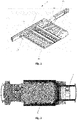
- Figure 2 shows a schematic diagram of a transmission path of a collision of an automobile.
- the front longitudinal beam 12, the side door sill 13 and the connecting member 14 form the transmission path 2 of a frontal collision of the automobile body, which effectively absorbs the energy from the frontal collision and protects the deformation of the front wall area of the automobile.
- the transverse support 15 is connected between the front longitudinal beam 12 and the side door sill beam 13.
- the detachable battery pack mounting beam 11 and the side door sill beam 13 are integrally connected together via the transverse support 15, to form the transmission path 2' of a side collision of the automobile body, which effectively absorbs the energy from the side collision and protects the deformation of the B-strut area of the automobile.
- the present embodiment further provides an automobile, which has an automobile body frame 1 described above.
- the automobile body frame and the automobile having the automobile body frame described in the present invention realize that the additional installation points of battery packs can effectively participate in the collision path and improve the collision security of the automobile body. Therefore, the present invention effectively overcomes various shortcomings in the prior art and has high industrial utilization value.
Landscapes
- Engineering & Computer Science (AREA)
- Chemical & Material Sciences (AREA)
- Combustion & Propulsion (AREA)
- Transportation (AREA)
- Mechanical Engineering (AREA)
- Body Structure For Vehicles (AREA)
Description
- The present invention belongs to the technical field of installation of automobile battery pack, and relates to an automobile body frame and an automobile, in particular to an automobile body frame and an automobile having the automobile body frame.
- As a representative of new energy vehicles, battery electric vehicles have received more and more attention because of their cleanliness and economy. However, the development of the battery electric vehicles is limited by battery capacity and charging time. The development of electric vehicles dawned with the emergence of electric vehicle power replacement stations combined with the concept of automatic quick-change equipment in recent years. The concept of electric vehicle power replacement is that when the battery of the electric vehicle is about to run out, the electric vehicle is driven into a power replacement station and the battery box is removed and replaced with a fully charged battery box. The entire power replacement process will be completed by the automatic power replacement equipment of the power replacement station and it only takes 3 minutes. That is, the battery replacement can be completed within a time when the ordinary diesel locomotive enters the gas station once, which greatly reduces the trouble with charging and battery maintenance for users of electric vehicles and increases the cruising range of electric vehicles in the meantime.
- Document
US2017/001667A1 provides a scalable vehicle frame for a vehicle, in which the battery subassembly is arranged at the middle section by the left center frame section and the right center frame section. DocumentCN205131383U provides a vehicle body frame in which the stiffening lower lateral beam is connected between the extension board leading portions of the front longitudinal beams and is perpendicular to the front longitudinal beams, and the battery package is fixed to the stiffening lower lateral beam by a bolt. DocumentCN106080803A provides a vehicle body frame in which a battery fixing structure is arranged inside the door sill beam to fix a battery package. - However, there are problems that in the event of a collision, the shape of the automobile cannot be better protected.
- Therefore, how to provide an automobile body frame and an automobile having the automobile body frame, to solve the problems that in the event of a collision, the shape of the automobile cannot be better protected, has become a technical problem to be solved by those skilled in the art.
- In view of the above-mentioned shortcomings of the prior art, an object of the present invention is to provide an automobile body frame and an automobile having the automobile body frame, to solve the problems that in the event of a collision, the shape of the automobile cannot be better protected.
- The invention is defined by the subject-matter of the
independent claim 1. Further aspects of the invention form the subject-matter of the dependent claims. - As described above, the automobile body frame and the automobile having the automobile body frame of the present invention have the following beneficial effects:
The automobile body frame and the automobile having the automobile body frame described in the present invention realize that the additional installation points of battery packs can effectively participate in the collision path and improve the collision security of the automobile body. -
-
Figure 1 shows a schematic diagram of an embodiment of an automobile body frame of the present invention. -
Figure 2 shows a schematic diagram of a transmission path of a collision of an automobile of the present invention. -
- 1
- Automobile body frame
- 10
- Floor
- 11
- Detachable battery pack mounting beam
- 12
- Front longitudinal beam
- 13
- Side door sill beam
- 14
- Connecting member
- 15
- Transverse support
- 2
- Transmission path of frontal collision of automobile body
- 2'
- Transmission path of side collision of automobile body
- In the following, the implementation of the present invention will be described by specific concrete embodiments, and those skilled in the art can easily understand other advantages and effects of the present invention from the contents disclosed in the present description.
- Please refer to
Figure 1 and Figure 2 . It should be noted that the structure, proportion, size, etc. shown in the drawings of the present description are only used to match the contents disclosed in the description, for those skilled in the art to understand and read, not used to limit defining conditions on which the present invention can be implemented, and thus do not have a technically significant meaning. Any modification of the structure, change in the proportional relationship or adjustment of the size, without affecting the effectiveness, which can be generated by the present invention, and the purpose, which can be achieved by the present invention, all should still fall into the scopes, which can be covered by the technical contents disclosed by the present invention. In the meantime, the terms such as "upper", "lower", "left", "right", "middle", "a" and "one" cited in the present description are also only used to facilitate the understanding of the description and not used to define the scopes, which can be implemented by the present invention, and the change or adjustment of the relative relationship of which, without substantial changes in the technical contents, should also be regarded as the scopes, which can be implemented by the present invention. The scope of the invention is defined only by the subject-matter of the appended claims. - The present embodiment provides an automobile body frame, which includes:
- a first type of battery pack; and
- a detachable battery pack mounting beam, with one side face thereof being arranged on a floor of the automobile body frame, and the other side face thereof being fitted with the first type of battery pack;
- The automobile body frame provided by the present embodiment will be described below in conjunction with the drawings. Please refer to
Figure 1 , which shows a schematic diagram of an embodiment of the automobile body frame. As shown inFigure 1 , theautomobile body frame 1 includes: a first type of battery pack, afloor 10, a detachable batterypack mounting beam 11, a frontlongitudinal beam 12, a sidedoor sill beam 13, a connectingmember 14 and atransverse support 15. - In the present embodiment, the first type of battery pack is a narrow battery pack, wherein the narrow battery pack has a width of 1040 mm.
- One side face of the detachable battery
pack mounting beam 11, which is used for mounting the narrow battery pack, is arranged on thefloor 10 of theautomobile body frame 1, and the other side face is mounted with the first type of battery pack (as shown inFigure 1 , the upper side face of the batterypack mounting beam 11 is connected at the underside of thefloor 10 in theautomobile body frame 1 via screws or bolts). - In the present embodiment, one end of the detachable battery
pack mounting beam 11 is inserted into a connectingmember 14. In the present embodiment, the connectingmember 14 is arranged between the frontlongitudinal beam 12 and the sidedoor sill beam 13 of the automobile body frame, and used for integrally connecting the frontlongitudinal beam 12 and the sidedoor sill beam 13 together. In the present embodiment, the connectingpiece 14 is made of aluminum casting and riveted to the root of the frontlongitudinal beam 12. - Please refer to
Figure 2 , which shows a schematic diagram of a transmission path of a collision of an automobile. As shown inFigure 2 , when the automobile is in collision, the frontlongitudinal beam 12, theside door sill 13 and the connectingmember 14 form thetransmission path 2 of a frontal collision of the automobile body, which effectively absorbs the energy from the frontal collision and protects the deformation of the front wall area of the automobile. - In the present embodiment, in order to protect the side of the automobile, the
transverse support 15 is connected between the frontlongitudinal beam 12 and the sidedoor sill beam 13. The detachable batterypack mounting beam 11 and the sidedoor sill beam 13 are integrally connected together via thetransverse support 15, to form the transmission path 2' of a side collision of the automobile body, which effectively absorbs the energy from the side collision and protects the deformation of the B-strut area of the automobile. - The present embodiment further provides an automobile, which has an
automobile body frame 1 described above. - In summary, the automobile body frame and the automobile having the automobile body frame described in the present invention realize that the additional installation points of battery packs can effectively participate in the collision path and improve the collision security of the automobile body. Therefore, the present invention effectively overcomes various shortcomings in the prior art and has high industrial utilization value.
- The above described embodiments are merely illustrative of the principles and effects of the present invention, and are not intended to limit the present invention. Those skilled in the art can modify or change the above embodiments without departing from the scope of the invention, as defined by the appended claims.
Claims (3)
- An automobile body frame, comprising:a battery pack; anda detachable battery pack mounting beam (11), with one side face thereof being arranged on a floor (10) of the automobile body frame (1), and the other side face thereof being fitted with the battery pack,characterized in that, one end of the detachable battery pack mounting beam (11) is inserted into a connecting member (14) which is arranged between a side door sill beam (13) and a front longitudinal beam (12) of the automobile body frame (1), the detachable battery pack mounting beam (11) and the side door sill beam (13) are arranged in a longitudinal direction and are integrally connected together via a transverse support (15), to form a transmission path (2') of a side collision of the automobile body.
- The automobile body frame according to claim 1, wherein the side door sill beam (13), the connecting member (14) and the front longitudinal beam (12) form a transmission path of a frontal collision of an automobile body (2).
- An automobile, characterized in by comprising an automobile body frame (1) according to claim 1 or 2.
Applications Claiming Priority (2)
| Application Number | Priority Date | Filing Date | Title |
|---|---|---|---|
| CN201721188575.6U CN207257348U (en) | 2017-09-15 | 2017-09-15 | Body shell and the automobile with the body shell |
| PCT/CN2018/105535 WO2019052511A1 (en) | 2017-09-15 | 2018-09-13 | Body frame and automobile having body frame |
Publications (3)
| Publication Number | Publication Date |
|---|---|
| EP3683079A1 EP3683079A1 (en) | 2020-07-22 |
| EP3683079A4 EP3683079A4 (en) | 2021-03-17 |
| EP3683079B1 true EP3683079B1 (en) | 2022-12-14 |
Family
ID=61921147
Family Applications (1)
| Application Number | Title | Priority Date | Filing Date |
|---|---|---|---|
| EP18857061.8A Active EP3683079B1 (en) | 2017-09-15 | 2018-09-13 | Body frame and automobile having automobile body frame |
Country Status (3)
| Country | Link |
|---|---|
| EP (1) | EP3683079B1 (en) |
| CN (1) | CN207257348U (en) |
| WO (1) | WO2019052511A1 (en) |
Families Citing this family (15)
| Publication number | Priority date | Publication date | Assignee | Title |
|---|---|---|---|---|
| CN207257348U (en) * | 2017-09-15 | 2018-04-20 | 爱驰汽车有限公司 | Body shell and the automobile with the body shell |
| JP7014075B2 (en) * | 2018-07-19 | 2022-02-01 | トヨタ自動車株式会社 | Body side structure |
| CN111430595A (en) * | 2019-01-09 | 2020-07-17 | 东风小康汽车有限公司重庆分公司 | A side beam of a battery pack assembly box body and a battery pack assembly box body |
| CN110509998B (en) * | 2019-08-30 | 2024-03-08 | 坤泰车辆系统(常州)有限公司 | Integral pure aluminum electric vehicle frame |
| MX2022007922A (en) | 2020-02-04 | 2022-07-27 | Nippon Steel Corp | Lateral surface member structure of vehicle body. |
| CN111873777A (en) * | 2020-07-06 | 2020-11-03 | 泽清新能源科技有限公司 | A frame assembly for electric vehicle power battery |
| CN112441140A (en) * | 2020-10-15 | 2021-03-05 | 阿尔特汽车技术股份有限公司 | Electric automobile threshold structure |
| CN114537525B (en) * | 2020-11-24 | 2023-08-22 | 上海汽车集团股份有限公司 | Automobile lower body and automobile thereof |
| CN112874286A (en) * | 2021-03-08 | 2021-06-01 | 广西汽车集团有限公司 | Electric automobile and electric automobile's battery protection mechanism |
| CN113602364B (en) * | 2021-07-28 | 2022-10-14 | 岚图汽车科技有限公司 | Threshold longeron, electric automobile body frame and electric automobile |
| JP2024539322A (en) * | 2021-10-29 | 2024-10-28 | 華為技術有限公司 | Integrated battery body structure and electric vehicle |
| CN113998003A (en) * | 2021-11-29 | 2022-02-01 | 浙江吉利控股集团有限公司 | Threshold roof beam subassembly and car |
| CN115871434A (en) * | 2023-01-19 | 2023-03-31 | 重庆赛力斯新能源汽车设计院有限公司 | A kind of automobile battery pack installation assembly and automobile |
| CN118003860B (en) * | 2024-02-28 | 2025-11-18 | 浙江极氪智能科技有限公司 | A vehicle body and vehicle |
| CN119018245B (en) * | 2024-08-22 | 2025-09-12 | 重庆长安汽车股份有限公司 | Door sill side beam and vehicle |
Family Cites Families (7)
| Publication number | Priority date | Publication date | Assignee | Title |
|---|---|---|---|---|
| JP5040566B2 (en) * | 2007-09-28 | 2012-10-03 | 三菱自動車工業株式会社 | Electric vehicle battery fixing structure |
| JP5906689B2 (en) * | 2011-11-22 | 2016-04-20 | トヨタ自動車株式会社 | Vehicle battery mounting structure |
| CN104648480A (en) * | 2015-02-09 | 2015-05-27 | 浙江吉利控股集团有限公司 | Lower automobile body structure of electric automobile |
| US10131381B2 (en) * | 2015-06-30 | 2018-11-20 | Faraday & Future Inc. | Joint for an underbody of a motor vehicle |
| US9499205B1 (en) * | 2015-09-23 | 2016-11-22 | Ford Global Technologies, Llc | Hybrid vehicle packaging system |
| CN205131383U (en) * | 2015-11-05 | 2016-04-06 | 北京汽车股份有限公司 | Roof beam structure assembly and electric automobile |
| CN207257348U (en) * | 2017-09-15 | 2018-04-20 | 爱驰汽车有限公司 | Body shell and the automobile with the body shell |
-
2017
- 2017-09-15 CN CN201721188575.6U patent/CN207257348U/en active Active
-
2018
- 2018-09-13 EP EP18857061.8A patent/EP3683079B1/en active Active
- 2018-09-13 WO PCT/CN2018/105535 patent/WO2019052511A1/en not_active Ceased
Also Published As
| Publication number | Publication date |
|---|---|
| WO2019052511A1 (en) | 2019-03-21 |
| CN207257348U (en) | 2018-04-20 |
| EP3683079A1 (en) | 2020-07-22 |
| EP3683079A4 (en) | 2021-03-17 |
Similar Documents
| Publication | Publication Date | Title |
|---|---|---|
| EP3683079A1 (en) | Body frame and automobile having body frame | |
| JP5823487B2 (en) | Vehicle and associated energy reservoir support | |
| CN208135150U (en) | Electric car electric charging device cabinet | |
| CN110171376A (en) | Front engine room collision energy-absorbing structure | |
| CN116278697A (en) | Battery devices for supplying energy to traction drives of partially electrically operated vehicles | |
| AU2021357407B2 (en) | Three-point support battery compartment for pure electric mining vehicle and battery shock absorption system | |
| CN105291800A (en) | Hybrid power automobile IPU fixing structure | |
| US20140174840A1 (en) | Subframe for holding an electric energy accumulator in a motor vehicle | |
| KR102281771B1 (en) | battery housing for electric vehicle | |
| CN213035648U (en) | Frame chassis with integrated battery pack | |
| CN201415652Y (en) | Rear bumper crossbeam assembly structure | |
| CN213861832U (en) | Battery pack installation frame capable of changing batteries and automobile with battery pack installation frame | |
| CN204726215U (en) | A kind of batteries of electric automobile bag and body connection structure | |
| JP2022014897A (en) | Driving battery system for automobile and automobile having electric drive equipment | |
| CN103029556A (en) | Vehicle structure | |
| US20150298740A1 (en) | Adapter for crush rail and torque box | |
| CN211391451U (en) | Reserve automobile body of continuation of journey formula electric automobile energy storage | |
| CN203766880U (en) | Auxiliary frame with retaining portion | |
| CN209496923U (en) | A kind of battery pack body structure | |
| CN218548651U (en) | New energy automobile battery package structure | |
| CN203293885U (en) | Automobile power battery assembly and new energy automobile with the same | |
| CN208848967U (en) | Electric automobile battery box cover plate unit | |
| CN216597824U (en) | Integrated structure of battery box and frame | |
| CN222408375U (en) | Lower body structure and vehicle | |
| CN223919103U (en) | Mounting structure and vehicle of battery package assembly |
Legal Events
| Date | Code | Title | Description |
|---|---|---|---|
| STAA | Information on the status of an ep patent application or granted ep patent |
Free format text: STATUS: THE INTERNATIONAL PUBLICATION HAS BEEN MADE |
|
| PUAI | Public reference made under article 153(3) epc to a published international application that has entered the european phase |
Free format text: ORIGINAL CODE: 0009012 |
|
| STAA | Information on the status of an ep patent application or granted ep patent |
Free format text: STATUS: REQUEST FOR EXAMINATION WAS MADE |
|
| 17P | Request for examination filed |
Effective date: 20200415 |
|
| AK | Designated contracting states |
Kind code of ref document: A1 Designated state(s): AL AT BE BG CH CY CZ DE DK EE ES FI FR GB GR HR HU IE IS IT LI LT LU LV MC MK MT NL NO PL PT RO RS SE SI SK SM TR |
|
| AX | Request for extension of the european patent |
Extension state: BA ME |
|
| DAV | Request for validation of the european patent (deleted) | ||
| DAX | Request for extension of the european patent (deleted) | ||
| A4 | Supplementary search report drawn up and despatched |
Effective date: 20210212 |
|
| RIC1 | Information provided on ipc code assigned before grant |
Ipc: B60K 1/04 20190101AFI20210208BHEP Ipc: B62D 21/15 20060101ALI20210208BHEP |
|
| STAA | Information on the status of an ep patent application or granted ep patent |
Free format text: STATUS: EXAMINATION IS IN PROGRESS |
|
| 17Q | First examination report despatched |
Effective date: 20220201 |
|
| GRAP | Despatch of communication of intention to grant a patent |
Free format text: ORIGINAL CODE: EPIDOSNIGR1 |
|
| STAA | Information on the status of an ep patent application or granted ep patent |
Free format text: STATUS: GRANT OF PATENT IS INTENDED |
|
| RIC1 | Information provided on ipc code assigned before grant |
Ipc: B62D 25/20 20060101ALN20220701BHEP Ipc: B62D 25/02 20060101ALN20220701BHEP Ipc: B62D 21/15 20060101ALI20220701BHEP Ipc: B60K 1/04 20190101AFI20220701BHEP |
|
| RIC1 | Information provided on ipc code assigned before grant |
Ipc: B62D 25/20 20060101ALN20220715BHEP Ipc: B62D 25/02 20060101ALN20220715BHEP Ipc: B62D 21/15 20060101ALI20220715BHEP Ipc: B60K 1/04 20190101AFI20220715BHEP |
|
| INTG | Intention to grant announced |
Effective date: 20220809 |
|
| GRAS | Grant fee paid |
Free format text: ORIGINAL CODE: EPIDOSNIGR3 |
|
| GRAA | (expected) grant |
Free format text: ORIGINAL CODE: 0009210 |
|
| STAA | Information on the status of an ep patent application or granted ep patent |
Free format text: STATUS: THE PATENT HAS BEEN GRANTED |
|
| AK | Designated contracting states |
Kind code of ref document: B1 Designated state(s): AL AT BE BG CH CY CZ DE DK EE ES FI FR GB GR HR HU IE IS IT LI LT LU LV MC MK MT NL NO PL PT RO RS SE SI SK SM TR |
|
| REG | Reference to a national code |
Ref country code: GB Ref legal event code: FG4D |
|
| REG | Reference to a national code |
Ref country code: CH Ref legal event code: EP |
|
| REG | Reference to a national code |
Ref country code: DE Ref legal event code: R096 Ref document number: 602018044345 Country of ref document: DE |
|
| REG | Reference to a national code |
Ref country code: IE Ref legal event code: FG4D |
|
| REG | Reference to a national code |
Ref country code: AT Ref legal event code: REF Ref document number: 1537472 Country of ref document: AT Kind code of ref document: T Effective date: 20230115 |
|
| REG | Reference to a national code |
Ref country code: LT Ref legal event code: MG9D |
|
| REG | Reference to a national code |
Ref country code: NL Ref legal event code: MP Effective date: 20221214 |
|
| PG25 | Lapsed in a contracting state [announced via postgrant information from national office to epo] |
Ref country code: SE Free format text: LAPSE BECAUSE OF FAILURE TO SUBMIT A TRANSLATION OF THE DESCRIPTION OR TO PAY THE FEE WITHIN THE PRESCRIBED TIME-LIMIT Effective date: 20221214 Ref country code: NO Free format text: LAPSE BECAUSE OF FAILURE TO SUBMIT A TRANSLATION OF THE DESCRIPTION OR TO PAY THE FEE WITHIN THE PRESCRIBED TIME-LIMIT Effective date: 20230314 Ref country code: LT Free format text: LAPSE BECAUSE OF FAILURE TO SUBMIT A TRANSLATION OF THE DESCRIPTION OR TO PAY THE FEE WITHIN THE PRESCRIBED TIME-LIMIT Effective date: 20221214 Ref country code: FI Free format text: LAPSE BECAUSE OF FAILURE TO SUBMIT A TRANSLATION OF THE DESCRIPTION OR TO PAY THE FEE WITHIN THE PRESCRIBED TIME-LIMIT Effective date: 20221214 |
|
| REG | Reference to a national code |
Ref country code: AT Ref legal event code: MK05 Ref document number: 1537472 Country of ref document: AT Kind code of ref document: T Effective date: 20221214 |
|
| PG25 | Lapsed in a contracting state [announced via postgrant information from national office to epo] |
Ref country code: RS Free format text: LAPSE BECAUSE OF FAILURE TO SUBMIT A TRANSLATION OF THE DESCRIPTION OR TO PAY THE FEE WITHIN THE PRESCRIBED TIME-LIMIT Effective date: 20221214 Ref country code: LV Free format text: LAPSE BECAUSE OF FAILURE TO SUBMIT A TRANSLATION OF THE DESCRIPTION OR TO PAY THE FEE WITHIN THE PRESCRIBED TIME-LIMIT Effective date: 20221214 Ref country code: HR Free format text: LAPSE BECAUSE OF FAILURE TO SUBMIT A TRANSLATION OF THE DESCRIPTION OR TO PAY THE FEE WITHIN THE PRESCRIBED TIME-LIMIT Effective date: 20221214 Ref country code: GR Free format text: LAPSE BECAUSE OF FAILURE TO SUBMIT A TRANSLATION OF THE DESCRIPTION OR TO PAY THE FEE WITHIN THE PRESCRIBED TIME-LIMIT Effective date: 20230315 |
|
| PG25 | Lapsed in a contracting state [announced via postgrant information from national office to epo] |
Ref country code: NL Free format text: LAPSE BECAUSE OF FAILURE TO SUBMIT A TRANSLATION OF THE DESCRIPTION OR TO PAY THE FEE WITHIN THE PRESCRIBED TIME-LIMIT Effective date: 20221214 |
|
| PG25 | Lapsed in a contracting state [announced via postgrant information from national office to epo] |
Ref country code: SM Free format text: LAPSE BECAUSE OF FAILURE TO SUBMIT A TRANSLATION OF THE DESCRIPTION OR TO PAY THE FEE WITHIN THE PRESCRIBED TIME-LIMIT Effective date: 20221214 Ref country code: RO Free format text: LAPSE BECAUSE OF FAILURE TO SUBMIT A TRANSLATION OF THE DESCRIPTION OR TO PAY THE FEE WITHIN THE PRESCRIBED TIME-LIMIT Effective date: 20221214 Ref country code: PT Free format text: LAPSE BECAUSE OF FAILURE TO SUBMIT A TRANSLATION OF THE DESCRIPTION OR TO PAY THE FEE WITHIN THE PRESCRIBED TIME-LIMIT Effective date: 20230414 Ref country code: ES Free format text: LAPSE BECAUSE OF FAILURE TO SUBMIT A TRANSLATION OF THE DESCRIPTION OR TO PAY THE FEE WITHIN THE PRESCRIBED TIME-LIMIT Effective date: 20221214 Ref country code: EE Free format text: LAPSE BECAUSE OF FAILURE TO SUBMIT A TRANSLATION OF THE DESCRIPTION OR TO PAY THE FEE WITHIN THE PRESCRIBED TIME-LIMIT Effective date: 20221214 Ref country code: CZ Free format text: LAPSE BECAUSE OF FAILURE TO SUBMIT A TRANSLATION OF THE DESCRIPTION OR TO PAY THE FEE WITHIN THE PRESCRIBED TIME-LIMIT Effective date: 20221214 Ref country code: AT Free format text: LAPSE BECAUSE OF FAILURE TO SUBMIT A TRANSLATION OF THE DESCRIPTION OR TO PAY THE FEE WITHIN THE PRESCRIBED TIME-LIMIT Effective date: 20221214 |
|
| PG25 | Lapsed in a contracting state [announced via postgrant information from national office to epo] |
Ref country code: SK Free format text: LAPSE BECAUSE OF FAILURE TO SUBMIT A TRANSLATION OF THE DESCRIPTION OR TO PAY THE FEE WITHIN THE PRESCRIBED TIME-LIMIT Effective date: 20221214 Ref country code: PL Free format text: LAPSE BECAUSE OF FAILURE TO SUBMIT A TRANSLATION OF THE DESCRIPTION OR TO PAY THE FEE WITHIN THE PRESCRIBED TIME-LIMIT Effective date: 20221214 Ref country code: IS Free format text: LAPSE BECAUSE OF FAILURE TO SUBMIT A TRANSLATION OF THE DESCRIPTION OR TO PAY THE FEE WITHIN THE PRESCRIBED TIME-LIMIT Effective date: 20230414 Ref country code: AL Free format text: LAPSE BECAUSE OF FAILURE TO SUBMIT A TRANSLATION OF THE DESCRIPTION OR TO PAY THE FEE WITHIN THE PRESCRIBED TIME-LIMIT Effective date: 20221214 |
|
| REG | Reference to a national code |
Ref country code: DE Ref legal event code: R097 Ref document number: 602018044345 Country of ref document: DE |
|
| PLBE | No opposition filed within time limit |
Free format text: ORIGINAL CODE: 0009261 |
|
| STAA | Information on the status of an ep patent application or granted ep patent |
Free format text: STATUS: NO OPPOSITION FILED WITHIN TIME LIMIT |
|
| PG25 | Lapsed in a contracting state [announced via postgrant information from national office to epo] |
Ref country code: DK Free format text: LAPSE BECAUSE OF FAILURE TO SUBMIT A TRANSLATION OF THE DESCRIPTION OR TO PAY THE FEE WITHIN THE PRESCRIBED TIME-LIMIT Effective date: 20221214 |
|
| 26N | No opposition filed |
Effective date: 20230915 |
|
| PG25 | Lapsed in a contracting state [announced via postgrant information from national office to epo] |
Ref country code: SI Free format text: LAPSE BECAUSE OF FAILURE TO SUBMIT A TRANSLATION OF THE DESCRIPTION OR TO PAY THE FEE WITHIN THE PRESCRIBED TIME-LIMIT Effective date: 20221214 |
|
| REG | Reference to a national code |
Ref country code: DE Ref legal event code: R119 Ref document number: 602018044345 Country of ref document: DE |
|
| REG | Reference to a national code |
Ref country code: CH Ref legal event code: PL |
|
| PG25 | Lapsed in a contracting state [announced via postgrant information from national office to epo] |
Ref country code: LU Free format text: LAPSE BECAUSE OF NON-PAYMENT OF DUE FEES Effective date: 20230913 |
|
| REG | Reference to a national code |
Ref country code: BE Ref legal event code: MM Effective date: 20230930 |
|
| GBPC | Gb: european patent ceased through non-payment of renewal fee |
Effective date: 20230913 |
|
| PG25 | Lapsed in a contracting state [announced via postgrant information from national office to epo] |
Ref country code: MC Free format text: LAPSE BECAUSE OF FAILURE TO SUBMIT A TRANSLATION OF THE DESCRIPTION OR TO PAY THE FEE WITHIN THE PRESCRIBED TIME-LIMIT Effective date: 20221214 Ref country code: LU Free format text: LAPSE BECAUSE OF NON-PAYMENT OF DUE FEES Effective date: 20230913 Ref country code: IT Free format text: LAPSE BECAUSE OF FAILURE TO SUBMIT A TRANSLATION OF THE DESCRIPTION OR TO PAY THE FEE WITHIN THE PRESCRIBED TIME-LIMIT Effective date: 20221214 |
|
| REG | Reference to a national code |
Ref country code: IE Ref legal event code: MM4A |
|
| PG25 | Lapsed in a contracting state [announced via postgrant information from national office to epo] |
Ref country code: IE Free format text: LAPSE BECAUSE OF NON-PAYMENT OF DUE FEES Effective date: 20230913 |
|
| PG25 | Lapsed in a contracting state [announced via postgrant information from national office to epo] |
Ref country code: GB Free format text: LAPSE BECAUSE OF NON-PAYMENT OF DUE FEES Effective date: 20230913 |
|
| PG25 | Lapsed in a contracting state [announced via postgrant information from national office to epo] |
Ref country code: CH Free format text: LAPSE BECAUSE OF NON-PAYMENT OF DUE FEES Effective date: 20230930 |
|
| PG25 | Lapsed in a contracting state [announced via postgrant information from national office to epo] |
Ref country code: IE Free format text: LAPSE BECAUSE OF NON-PAYMENT OF DUE FEES Effective date: 20230913 Ref country code: GB Free format text: LAPSE BECAUSE OF NON-PAYMENT OF DUE FEES Effective date: 20230913 Ref country code: FR Free format text: LAPSE BECAUSE OF NON-PAYMENT OF DUE FEES Effective date: 20230930 Ref country code: DE Free format text: LAPSE BECAUSE OF NON-PAYMENT OF DUE FEES Effective date: 20240403 Ref country code: CH Free format text: LAPSE BECAUSE OF NON-PAYMENT OF DUE FEES Effective date: 20230930 |
|
| PG25 | Lapsed in a contracting state [announced via postgrant information from national office to epo] |
Ref country code: BE Free format text: LAPSE BECAUSE OF NON-PAYMENT OF DUE FEES Effective date: 20230930 |
|
| PG25 | Lapsed in a contracting state [announced via postgrant information from national office to epo] |
Ref country code: BG Free format text: LAPSE BECAUSE OF FAILURE TO SUBMIT A TRANSLATION OF THE DESCRIPTION OR TO PAY THE FEE WITHIN THE PRESCRIBED TIME-LIMIT Effective date: 20221214 |
|
| PG25 | Lapsed in a contracting state [announced via postgrant information from national office to epo] |
Ref country code: BG Free format text: LAPSE BECAUSE OF FAILURE TO SUBMIT A TRANSLATION OF THE DESCRIPTION OR TO PAY THE FEE WITHIN THE PRESCRIBED TIME-LIMIT Effective date: 20221214 |
|
| PG25 | Lapsed in a contracting state [announced via postgrant information from national office to epo] |
Ref country code: CY Free format text: LAPSE BECAUSE OF FAILURE TO SUBMIT A TRANSLATION OF THE DESCRIPTION OR TO PAY THE FEE WITHIN THE PRESCRIBED TIME-LIMIT; INVALID AB INITIO Effective date: 20180913 |
|
| PG25 | Lapsed in a contracting state [announced via postgrant information from national office to epo] |
Ref country code: HU Free format text: LAPSE BECAUSE OF FAILURE TO SUBMIT A TRANSLATION OF THE DESCRIPTION OR TO PAY THE FEE WITHIN THE PRESCRIBED TIME-LIMIT; INVALID AB INITIO Effective date: 20180913 |
|
| PG25 | Lapsed in a contracting state [announced via postgrant information from national office to epo] |
Ref country code: TR Free format text: LAPSE BECAUSE OF FAILURE TO SUBMIT A TRANSLATION OF THE DESCRIPTION OR TO PAY THE FEE WITHIN THE PRESCRIBED TIME-LIMIT Effective date: 20221214 |