EP3683041A1 - Production method and production device for stereoscopic decoration piece made of thermoplastic synthetic resin - Google Patents
Production method and production device for stereoscopic decoration piece made of thermoplastic synthetic resin Download PDFInfo
- Publication number
- EP3683041A1 EP3683041A1 EP18916678.8A EP18916678A EP3683041A1 EP 3683041 A1 EP3683041 A1 EP 3683041A1 EP 18916678 A EP18916678 A EP 18916678A EP 3683041 A1 EP3683041 A1 EP 3683041A1
- Authority
- EP
- European Patent Office
- Prior art keywords
- decorative piece
- die
- piece material
- flat
- fusion
- Prior art date
- Legal status (The legal status is an assumption and is not a legal conclusion. Google has not performed a legal analysis and makes no representation as to the accuracy of the status listed.)
- Granted
Links
Images







Classifications
-
- B—PERFORMING OPERATIONS; TRANSPORTING
- B32—LAYERED PRODUCTS
- B32B—LAYERED PRODUCTS, i.e. PRODUCTS BUILT-UP OF STRATA OF FLAT OR NON-FLAT, e.g. CELLULAR OR HONEYCOMB, FORM
- B32B38/00—Ancillary operations in connection with laminating processes
- B32B38/18—Handling of layers or the laminate
- B32B38/1825—Handling of layers or the laminate characterised by the control or constructional features of devices for tensioning, stretching or registration
- B32B38/1833—Positioning, e.g. registration or centering
- B32B38/1841—Positioning, e.g. registration or centering during laying up
- B32B38/185—Positioning, e.g. registration or centering during laying up combined with the cutting of one or more layers
-
- B—PERFORMING OPERATIONS; TRANSPORTING
- B29—WORKING OF PLASTICS; WORKING OF SUBSTANCES IN A PLASTIC STATE IN GENERAL
- B29C—SHAPING OR JOINING OF PLASTICS; SHAPING OF MATERIAL IN A PLASTIC STATE, NOT OTHERWISE PROVIDED FOR; AFTER-TREATMENT OF THE SHAPED PRODUCTS, e.g. REPAIRING
- B29C65/00—Joining or sealing of preformed parts, e.g. welding of plastics materials; Apparatus therefor
- B29C65/02—Joining or sealing of preformed parts, e.g. welding of plastics materials; Apparatus therefor by heating, with or without pressure
- B29C65/04—Dielectric heating, e.g. high-frequency welding, i.e. radio frequency welding of plastic materials having dielectric properties, e.g. PVC
-
- B—PERFORMING OPERATIONS; TRANSPORTING
- B29—WORKING OF PLASTICS; WORKING OF SUBSTANCES IN A PLASTIC STATE IN GENERAL
- B29C—SHAPING OR JOINING OF PLASTICS; SHAPING OF MATERIAL IN A PLASTIC STATE, NOT OTHERWISE PROVIDED FOR; AFTER-TREATMENT OF THE SHAPED PRODUCTS, e.g. REPAIRING
- B29C65/00—Joining or sealing of preformed parts, e.g. welding of plastics materials; Apparatus therefor
- B29C65/74—Joining or sealing of preformed parts, e.g. welding of plastics materials; Apparatus therefor by welding and severing, or by joining and severing, the severing being performed in the area to be joined, next to the area to be joined, in the joint area or next to the joint area
- B29C65/743—Joining or sealing of preformed parts, e.g. welding of plastics materials; Apparatus therefor by welding and severing, or by joining and severing, the severing being performed in the area to be joined, next to the area to be joined, in the joint area or next to the joint area using the same tool for both joining and severing, said tool being monobloc or formed by several parts mounted together and forming a monobloc
-
- B—PERFORMING OPERATIONS; TRANSPORTING
- B29—WORKING OF PLASTICS; WORKING OF SUBSTANCES IN A PLASTIC STATE IN GENERAL
- B29C—SHAPING OR JOINING OF PLASTICS; SHAPING OF MATERIAL IN A PLASTIC STATE, NOT OTHERWISE PROVIDED FOR; AFTER-TREATMENT OF THE SHAPED PRODUCTS, e.g. REPAIRING
- B29C66/00—General aspects of processes or apparatus for joining preformed parts
- B29C66/70—General aspects of processes or apparatus for joining preformed parts characterised by the composition, physical properties or the structure of the material of the parts to be joined; Joining with non-plastics material
- B29C66/71—General aspects of processes or apparatus for joining preformed parts characterised by the composition, physical properties or the structure of the material of the parts to be joined; Joining with non-plastics material characterised by the composition of the plastics material of the parts to be joined
-
- B—PERFORMING OPERATIONS; TRANSPORTING
- B32—LAYERED PRODUCTS
- B32B—LAYERED PRODUCTS, i.e. PRODUCTS BUILT-UP OF STRATA OF FLAT OR NON-FLAT, e.g. CELLULAR OR HONEYCOMB, FORM
- B32B37/00—Methods or apparatus for laminating, e.g. by curing or by ultrasonic bonding
- B32B37/06—Methods or apparatus for laminating, e.g. by curing or by ultrasonic bonding characterised by the heating method
-
- B—PERFORMING OPERATIONS; TRANSPORTING
- B44—DECORATIVE ARTS
- B44C—PRODUCING DECORATIVE EFFECTS; MOSAICS; TARSIA WORK; PAPERHANGING
- B44C3/00—Processes, not specifically provided for elsewhere, for producing ornamental structures
- B44C3/02—Superimposing layers
Definitions
- the present invention relates to a method and a device for producing a three-dimensional decorative piece made of a thermoplastic synthetic resin, such as an emblem to be attached to a car, a motorbike, a boat, a household electrical appliance, a game console, clothes, a bag, a cap, or the like, and more specifically relates to a method and a device with which a bulky three-dimensional decorative piece made of a thermoplastic synthetic resin can be produced.
- a decorative piece is produced from a decorative piece material that includes a thermoplastic resin sheet, a vapor-deposited metal layer, a foamed resin sheet, and the like.
- a decorative piece material that includes a thermoplastic resin sheet, a vapor-deposited metal layer, a foamed resin sheet, and the like.
- Patent Document 1 while a decorative piece material is sandwiched between an engraved die and a flat-plate die, high-frequency dielectric heating is performed, thereby shaping the decorative piece material while heating and welding the material.
- the engraved die is provided with fusion-cutting blades along outlines of a design of a decorative piece to be produced, so that fusion-cutting can be performed simultaneously with shaping.
- Patent Document 1 Japanese Patent No. 3235943
- An object of the present invention is to provide a method and a device with which a bulky decorative piece made of a thermoplastic synthetic resin can be produced.
- a method for producing a three-dimensional decorative piece made of a thermoplastic synthetic resin according to the present invention includes:
- the method can include:
- the method can include:
- the method can include:
- the method can include:
- a device for producing a three-dimensional decorative piece made of a thermoplastic synthetic resin is a device for producing a decorative piece made of a thermoplastic synthetic resin by shaping a decorative piece material including an upper layer that has a thermoplastic synthetic resin film and a lower layer that has a thermoplastic synthetic resin sheet through high-frequency dielectric heating and fusion-cutting the decorative piece material using a fusion-cutting blade, the device including:
- a device for producing a three-dimensional decorative piece made of a thermoplastic synthetic resin is a device for producing a decorative piece made of a thermoplastic synthetic resin by shaping a decorative piece material including an upper layer that has a thermoplastic synthetic resin film and a lower layer that has a thermoplastic synthetic resin sheet through high-frequency dielectric heating and fusion-cutting the decorative piece material using a fusion-cutting blade, the device including:
- a device for producing a three-dimensional decorative piece made of a thermoplastic synthetic resin is a device for producing a decorative piece made of a thermoplastic synthetic resin by shaping a decorative piece material including an upper layer that has a thermoplastic synthetic resin film and a lower layer that has a thermoplastic synthetic resin sheet through high-frequency dielectric heating and fusion-cutting the decorative piece material using a fusion-cutting blade, the device including:
- the entire decorative piece material can be heated and softened by performing high-frequency dielectric heating on the decorative piece material using the flat-plate dies. Since the entire decorative piece material is heated and softened through high-frequency dielectric heating prior to the shaping, the decorative piece material can be shaped using the engraved die in the subsequent shaping step even when the decorative piece material is thick, and thus, a bulky three-dimensional decorative piece made of a thermoplastic synthetic resin that has a three-dimensional appearance and a sense of luxuriousness can be favorably produced.
- the device for producing a three-dimensional decorative piece made of a thermoplastic synthetic resin according to the present invention it is possible to shape the decorative piece material using the engraved die and/or the engraved die with the fusion-cutting blade immediately after softening the decorative piece material using the flat-plate die, by sliding the dies after the softening.
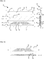
- FIG. 18 is an explanatory diagram of the production method that uses a third production device of the present invention.
- a three-dimensional decorative piece 90 made of a thermoplastic synthetic resin of the present invention and a method for producing the three-dimensional decorative piece 90 will be described with reference to the drawings.
- the thicknesses of the decorative piece 90 and layers of a decorative piece material 91, projections and recesses of dies, the thicknesses of the dies, and the like are shown exaggerated to facilitate the explanation.
- the shapes, the designs, and the like of the decorative piece 90 and the decorative piece material 91 are given by way of example only, and can be changed as appropriate.
- FIG. 1 is a cross-sectional view of the decorative piece material 91. As shown in FIG. 1 , the decorative piece material 91 includes an upper layer 92 and a lower layer 93.
- the upper layer 92 is a laminated film including a thermoplastic synthetic resin film that can be molded through high-frequency dielectric heating, a vapor-deposited metal layer, and the like.
- the thermoplastic synthetic resin film may be made of a soft thermoplastic synthetic resin, such as polyvinyl chloride or polyurethane, for example.
- the upper layer 92 can be formed by, for example, forming the vapor-deposited metal layer on the thermoplastic synthetic resin film that is located on the upper surface side through metal vapor deposition.
- the upper layer 92 may also have a configuration in which a migration preventing film is provided on a lower surface of the vapor-deposited metal layer via an adhesive layer, if necessary, and furthermore a thermoplastic synthetic resin film may be provided thereunder via an adhesive layer.
- the migration preventing film is an ethylene-vinyl alcohol copolymer (EVOH) film.
- EVOH ethylene-vinyl alcohol copolymer
- a desired design can also be printed in a desired color onto an upper surface of the upper layer 92 using a transparent color ink, a matte ink, a glossy ink, or the like.
- a fine line design can also be added by screen printing an ultraviolet-curable transparent UV ink or the like onto the above-described printing, so that a sense of luxuriousness such as that of braided embroidery, an aura of substance, elaborateness, a depth of color, and a metallic appearance, and furthermore, minute projections and depressions, and the like can also be expressed.
- a soft sheet of a thermoplastic synthetic resin or a foamed resin sheet can be used as the lower layer 93, and the lower layer 93 may be made of a thermoplastic synthetic resin, such as soft polyvinyl chloride (PVC), for example.
- PVC polyvinyl chloride
- the decorative piece material 91 a material in which a foamed resin sheet or the like is thicker than that of a conventional material can be used as the decorative piece material 91.
- the decorative piece material 91 may have a total thickness of greater than 2 mm, and the shaping of a decorative piece material having such a thickness has been difficult with a conventional method.
- the decorative piece material 91 has a thickness of preferably about 2.3 mm to 6 mm, but the present invention is also applicable to a decorative piece material having a greater thickness.
- a feature of the present invention is that the decorative piece material 91 is softened through high-frequency dielectric heating in advance, and then high-frequency dielectric heating is performed again to thereby perform shaping and fusion-cutting.
- the step of softening the decorative piece material 91 can be performed by performing high-frequency dielectric heating while the decorative piece material 91 is sandwiched between a first flat-plate die 20 and a second flat-plate die 21, which serve as electrodes.
- the decorative piece material 91 is placed on top of the first flat-plate die 20 as illustrated in FIG. 2(a)
- the second flat-plate die 21 is brought closer to the first flat-plate die 20 as illustrated in FIG. 2(b)
- high-frequency dielectric heating is performed.
- insulators of the upper layer 92 and the lower layer 93 of the decorative piece material 91 generate heat and fuse, allowing both layers to be softened in their entirety and welded to each other.
- the second flat-plate die 21 is separated from the decorative piece material 91 as illustrated in FIG. 2(c) .
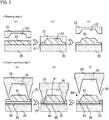
- the decorative piece material 91 is shaped as illustrated in FIGS. 3(a) to 3(c) (shaping step), and subsequently the shaped decorative piece material 91 is fusion-cut as illustrated in FIGS. 3(d) to 3(f) (fusion-cutting step).
- the first flat-plate die 20 is used, and an engraved die 22 is used in place of the second flat-plate die 21 in FIG. 2 .
- the engraved die 22 is a die in which recesses 23 of a design to be formed in the decorative piece material 91 are formed. While the decorative piece material 91 that is in a softened state due to the softening step is still placed on top of the first flat-plate die 20, the engraved die 22 is brought closer to the first flat-plate die 20 as illustrated in FIG. 3(b) , and high-frequency dielectric heating is performed.
- the decorative piece material 91 is shaped in conformity with the recesses 23 of the engraved die 22 as illustrated in FIG. 3(c) .
- the shaping step since the decorative piece material 91 that is softened in its entirety in advance is shaped, the shaping can be performed even when the decorative piece material 91 is thick. Note that, after the shaping, the decorative piece material 91 is cooled to fix its shape.
- the decorative piece material 91 is fusion-cut along the design.
- the fusion-cutting step first, as illustrated in FIG. 3(d) , the decorative piece material 91 with a piece of release paper 95 disposed on or attached to the lower layer 93 side thereof via a piece of double-sided tape 94 is placed on top of the first flat-plate die 20.
- the double-sided tape 94 is used to attach the produced decorative piece 90 to various products and the like.
- an engraved die 24 with fusion-cuttings blade is used in place of the engraved die 22.
- the engraved die 24 with the fusion-cutting blades is a die in which fusion-cutting blades 25 are formed at peripheral edges of recesses 26 along outlines of the design to be formed in the decorative piece material 91. If the fusion-cutting blades 25 come into surface contact with the decorative piece material 91 that has been shaped using the engraved die 22, the dielectric heating efficiency decreases, resulting in a deformation or the like of the already shaped decorative piece material 91. For this reason, it is desirable that, as illustrated in FIG.
- the fusion-cutting blades 25 have a sharper angle than the engraved die 22 so as not to come into surface contact with the decorative piece material 91.
- the engraved die 24 with the fusion-cutting blades is brought closer to the first flat-plate die 20 as illustrated in FIG. 3(e) , and high-frequency dielectric heating is performed.
- the decorative piece material 91 and the double-sided tape 94 are fusion-cut or cut by the fusion-cutting blades 25 as illustrated in FIG. 3(f) .
- the release paper 95 is not cut by the fusion-cutting blades 25.
- the shaped and fusion-cut design and unnecessary portions of the decorative piece material 91 remain on the release paper 95 in a state in which the design and the unnecessary portions are separately attached to the double-sided tape 94. After that, the unnecessary portions are eliminated, and an application film is attached to the upper layer 92 side of the decorative piece material 91 so as to prevent displacement of the design.
- the application film include, but are not limited to, sheets in which an acrylic pressure-sensitive adhesive is applied to a polyester film or paper.
- the obtained decorative piece 90 can be affixed to a product by peeling off the release paper 95 and attaching the decorative piece 90 to the product via the double-sided tape 94 in a state in which the application film or the like is attached to the decorative piece 90, and then peeling off the application film or the like.
- a decorative piece 90 can be produced by performing the shaping step and the fusion-cutting step by replacing the dies after the softening step.
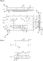
- FIGS. 4 and 5 show an example of the production device 10 that can be used in the present embodiment.
- the production device 10 may be constituted by a first jig 30 shown in FIG. 4 and a second jig 50 shown in FIG. 5 .
- the first jig 30 and the second jig 50 constitute the production device 10 in which, as shown in FIG. 10 , which will be described later, the first jig 30 is arranged on the lower side and the second jig 50 is arranged on the upper side.
- a rectangular first frame 32 is mounted on an upper surface of a rectangular bottom plate 31.
- the first frame 32 includes first guide members 33 on an inner surface side thereof in a left-right direction, which is a width direction, the first guide members 33 extending parallel to each other.
- a first slide plate 34 is slidably engaged with the first guide members 33.
- the first slide plate 34 has a length that is 2/3 of the length of the first frame 32 (first guide members 33).
- a plurality of tapped holes 35 to which a die, which will be described later, is to be fastened are formed in the first slide plate 34, and two dies can be mounted on the first slide plate 34 in a length direction.
- pin holes 37 for achieving alignment with the second jig 50 are formed at a plurality of locations in the first frame 32.
- Means for preventing displacement such as magnets 38 and 39 are arranged in end faces in the length direction of the first frame 32 and the first slide plate 34, and when the first slide plate 34 is slid and abutted against the first frame 32, the magnets 38 and 39 are attracted to each other, thereby restraining the first slide plate 34 from moving freely.
- the first jig 30 is configured such that one wire (lower board) of a high-frequency molding machine, which is not shown, can be connected to the center of a lower surface of the bottom plate 31, and high-frequency dielectric heating is applied to a portion indicated by the oblique lines in FIG. 4 .
- the region that is subjected to the high-frequency dielectric heating is a region that occupies 1/2 of the first slide plate 34 in the length direction and 1/3 of the first frame 32 in the length direction and is located centrally in the length direction of the first frame 32.
- the first jig 30 is configured such that, when the first slide plate 34 is slid in a direction indicated by the arrows in FIG. 4(a) , the first slide plate 34 can be slid to the front side, which is the lower side in the paper plane, as shown in FIGS. 4(a) and 4(b) and positioned by the magnets 38 and 39 attracting each other. Moreover, in the case where the first slide plate 34 is slid to the back side, which is the upper side in the paper plane, as well, the first slide plate 34 can be positioned by the magnets 38 and 39 attracting each other.
- a rectangular second frame 52 is mounted on a lower surface of a rectangular top plate 51.
- the second frame 52 includes second guide members 53 on an inner surface side thereof in the left-right direction, which is the width direction, the second guide members 53 extending parallel to each other.
- the second guide members 53 are formed so as to extend in the same direction as the first guide members 33.
- a second slide plate 54 is slidably engaged with the second guide members 53.
- the second slide plate 54 has a length that is 2/3 of the length of the second frame 52 (second guide members 53).
- a plurality of tapped holes 55 to which a die, which will be described later, is to be fastened are formed in the second slide plate 54, and two dies can be mounted on the second slide plate 54 in the length direction.
- pin holes 57 for achieving alignment with the first jig 30 are formed at a plurality of locations in the second frame 52.
- Means for preventing displacement such as magnets 58 and 59 are arranged in end faces in the length direction of the second frame 52 and the second slide plate 54, and when the second slide plate 54 is slid and abutted against the second frame 52, the magnets 58 and 59 are attracted to each other, thereby restraining the second slide plate 54 from moving freely.
- a cross-shaped bar 51a in which a plurality of screw holes are formed is mounted on an upper surface of the top plate 51, so that the second jig 50 can be fastened to an upper board (not shown) of the high-frequency molding machine, which is not shown, using a bolt or the like.
- high-frequency dielectric heating is performed on a portion indicated by the oblique lines in FIG. 5 .
- the region that is subjected to the high-frequency dielectric heating is a region that occupies 1/2 of the second slide plate 54 in the length direction and 1/3 of the second frame 52 in the length direction and is located centrally in the length direction of the second frame 52. This region opposes the high-frequency dielectric heating region of the first jig 30 shown in FIG. 4 .
- the second jig 50 is configured such that, when the second slide plate 54 is slid in a direction indicated by the arrows in FIG. 5(a) , the second slide plate 54 can be slid to the back side, which is the lower side in the paper plane, as shown in FIGS. 5(a) and 5(b) , and positioned by the magnets 58 and 59 attracting each other. Moreover, in the case where the second slide plate 54 is slid to the front side, which is the upper side in the paper plane, as well, the second slide plate 54 can be positioned by the magnets 58 and 59 attracting each other.
- dies are mounted on the first slide plate 34 and the second slide plate 54.
- FIG. 6 shows the first jig 30 to which dies 40 and 41 are mounted
- FIG. 7 shows the dies 40 and 41 that are to be mounted to the first jig 30.
- the dies 40 and 41 can be mounted on the first slide plate 34 by fastening screws 36 to the tapped holes 35.
- the dies to be fastened to the first jig 30 may be the first flat-plate die 40 shown in FIG. 7(a) and the first engraved die 41 with fusion-cutting blades shown in FIG. 7(b) .
- the first flat-plate die 40 is a die that has a flat upper surface
- the first engraved die 41 with the fusion-cutting blades is a die in which fusion-cutting blades 42 are formed along the outlines of the design of the decorative piece material 91.
- FIG. 8 shows the second jig 50 to which dies 60 and 61 are mounted
- FIG. 9 shows the dies 60 and 61 that are to be mounted to the second jig 50.
- the dies 60 and 61 can be mounted on the second slide plate 54 by fastening screws 56 to the tapped holes 55.
- the dies to be fastened to the second jig 50 may be the second flat-plate die 60 shown in FIG. 9(a) and the second engraved die 61 shown in FIG. 9(b) .
- the second flat-plate die 60 is a die that has a flat lower surface
- the second engraved die 61 is a die in which recesses 62 of the design of the decorative piece material 91 are formed. For example, recesses 62 that constitute inverted alphabet letters "CHRO" are formed in the second engraved die 61 shown in FIG. 9 .
- the first jig 30 and the second jig 50 on which the dies 40 and 41 and the dies 60 and 61 are respectively mounted are fastened to a high-frequency dielectric heating device, which is not shown, such that the first jig 30 is located on the lower side and the second jig 50 is located on the upper side.
- the positions of both jigs are adjusted by inserting pins (not shown) into the pin holes 37 and 57.
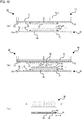
- the softening step (see FIG. 2 ) of softening the decorative piece material 91 is performed using the production device 10.
- the slide plates 34 and 54 are positioned such that the flat-plate dies 40 and 60 are located centrally (in the portions indicated by the oblique lines in FIGS. 6 and 8 ), and the decorative piece material 91 is placed on top of the first flat-plate die 40.
- the second jig 50 is moved downward, and while the decorative piece material 91 is thereby pressed, high-frequency dielectric heating is performed using the flat-plate dies 40 and 60 as electrodes, thereby softening and welding the entire decorative piece material 91.
- the second jig 50 is moved upward.
- the second slide plate 54 of the second jig 50 is slid to the back side, thereby moving the second engraved die 61 to the center (the portion indicated by the oblique lines in FIG. 8 ) as illustrated in FIG. 10(b) .
- the second jig 50 is moved downward, and while the decorative piece material 91 is thereby pressed, high-frequency dielectric heating is performed using the first flat-plate die 40 and the second engraved die 61 as electrodes (shaping step in FIGS. 3(a) to 3(c) ).
- the decorative piece material 91 Since the entire decorative piece material 91 is softened due to the softening step, the decorative piece material 91 is shaped in conformity with the recesses 62 of the second engraved die 61 through high-frequency dielectric heating, and thus the design is formed therein as projections and recesses. When the shaping is completed, the decorative piece material 91 is temporarily cooled to fix the shape.
- the first slide plate 34 of the first jig 30 is slid to the back side, thereby moving the first engraved die 41 with the fusion-cutting blades to the center (the portion indicated by the oblique lines in FIG. 6 ), and the second slide plate 54 of the second jig 50 is slid to the front side, thereby moving the second flat-plate die 60 to the center (the portion indicated by the oblique lines in FIG. 8 ).
- the decorative piece material 91 is disposed, with its surface that has served as the lower surface in the shaping step facing upward, such that the shaped design is fitted into the first engraved die 41 with the fusion-cutting blades.
- the double-sided tape 94 to which the release paper 95 is attached is placed on or attached to the decorative piece material 91 from above such that the release paper 95 is located on the upper side.
- the second jig 50 is moved downward, and while the decorative piece material 91 is thereby pressed, high-frequency dielectric heating is performed using the first engraved die 41 with the fusion-cutting blades and the second flat-plate die 60 as electrodes (fusion-cutting step in FIGS. 3(d) to 3(f) ).
- the decorative piece material 91 and the double-sided tape 94 are fusion-cut along the outlines of the design by the fusion-cutting blades 42.
- the second jig 50 is moved upward, and the decorative piece material 91 is removed.
- the decorative piece material 91 can be removed from the production device 10 without positional displacement occurring. In this state, unnecessary portions are eliminated from the decorative piece material 91, and the application film 96 is attached to a surface of the decorative piece material 91 on the opposite side to the release paper 95. Thus, a decorative piece 90 can be obtained as illustrated in FIG. 10(d) .
- the obtained decorative piece 90 can be affixed to a product without positional displacement occurring, by peeling off the release paper 95, attaching the decorative piece 90 to the product via the double-sided tape 94, and then peeling off the application film 96.
- the slide plates 34 and 54 are respectively disposed in the first jig 30 and the second jig 50, and different types of dies are fastened to these slide plates 34 and 54. Therefore, replacement of the dies can be achieved simply by sliding the slide plates 34 and 54, and the softening step ( FIG. 2 ), the shaping step ( FIGS. 3(a) to 3(c) ), and the fusion-cutting step ( FIGS. 3(d) to 3(f) ) can be performed immediately one after another using the same device.
- the softening step allows the entire decorative piece material 91 to be softened in advance even when the decorative piece material 91 is thick
- the above-described embodiment is particularly preferable for the production of a bulky decorative piece 90 having a three-dimensional appearance and a sense of luxuriousness.
- a decorative piece material 91 that is 2.3 mm to 6 mm thick is used, a decorative piece 90 having a thickness of 2.5 mm to 6.2 mm can be produced.
- the decorative piece material 91 is subjected to the softening step illustrated in FIG. 2 .
- the shaping and fusion-cutting step can be performed by performing high-frequency dielectric heating using the flat-plate die 20 on one hand and the engraved die 24 with the fusion-cutting blades, in which the recesses 26 of the design are formed and the fusion-cutting blades 25 are formed along the outlines of the design, on the other hand.
- the engraved die 24 with the fusion-cutting blades shown in FIGS. 11(a) to 11(c) is a die in which the recesses 26 are formed to have a depth that is greater than the thickness of a decorative piece 90 to be obtained.
- the engraved die 24 with the fusion-cutting blades is used in place of the second flat-plate die 21 used in the softening step (see FIG. 2 ), and as illustrated in FIG. 11(a) , the decorative piece material 91 that is in the softened state due to the softening step is placed on top of the flat-plate die 20, with the release paper 95 disposed on the lower layer 93 side of the decorative piece material 91, or attached to the decorative piece material 91, via the double-sided tape 94. Then, as illustrated in FIG. 11(b) , the engraved die 24 with the fusion-cutting blades is brought closer to the flat-plate die 20, and high-frequency dielectric heating is performed. Thus, the decorative piece material 91 is shaped as illustrated in FIG.
- the recesses 26 of the engraved die 24 with the fusion-cutting blades are formed to have a depth that is greater than the thickness of the decorative piece 90, a top portion of the decorative piece 90 is shaped without abutting against a bottom surface of the die. As a result, a decorative piece 90 with a design having a slightly round-shaped curve can be obtained.
- the decorative piece material 91 is fusion-cut or cut together with the double-sided tape 94 by the fusion-cutting blades 25 as illustrated in FIGS. 11(b) and 11(c) .
- a decorative piece 90 can be produced by performing the shaping and fusion-cutting step by replacing the die after the softening step.
- the production device 10 shown in FIGS. 4 and 5 is used in which dies different from those of the first embodiment are mounted as the production device 10.
- the first flat-plate die 40 is mounted on the first slide plate 34
- the second flat-plate die 60 illustrated in FIG. 12(a) and a second engraved die 64 with fusion-cutting blades are mounted on the second slide plate 54.
- the second engraved die 64 with the fusion-cutting blades has recesses 65 having a depth that is greater than the thickness of the decorative piece 90 to be obtained, and includes fusion-cutting blades 66 at peripheral edges of the recesses 65.
- the first jig 30 and the second jig 50 to which the die 40 and the dies 60 and 64 are respectively mounted are fastened to a high-frequency dielectric heating device, which is not shown, such that the first jig 30 is located on the lower side and the second jig 50 is located on the upper side.
- the softening step (see FIG. 2 ) of softening the decorative piece material 91 is performed using the production device 10.
- the slide plates 34 and 54 are positioned such that the flat-plate dies 40 and 60 are located centrally, and the decorative piece material 91 is placed on top of the first flat-plate die 40.
- the second jig 50 is moved downward, and while the decorative piece material 91 is thereby pressed, high-frequency dielectric heating is performed using the flat-plate dies 40 and 60 as electrodes, thereby softening and welding the entire decorative piece material 91.
- the second jig 50 is moved upward.
- the second slide plate 54 of the second jig 50 is slid, thereby moving the second engraved die 64 with the fusion-cutting blades to the center as illustrated in FIG. 12(b) .
- the double-sided tape 94 to which the release paper 95 is attached is disposed on the first flat-plate die 40 of the first jig 30 or attached to the decorative piece material 91, and the decorative piece material 91 is placed thereon with the upper layer 92 facing upward.
- the second jig 50 is moved downward, and while the decorative piece material 91 is thereby pressed, high-frequency dielectric heating is performed using the first flat-plate die 40 and the second engraved die 64 with the fusion-cutting blades as electrodes (shaping step in FIGS. 11(a) to 11(c) ). Since the entire decorative piece material 91 is softened due to the softening step, the decorative piece material 91 is shaped within the recesses 65 of the second engraved die 64 with the fusion-cutting blades through high-frequency dielectric heating, and thus, a design with a slightly round-shaped surface is formed.
- the decorative piece material 91 and the double-sided tape 94 are fusion-cut along the outlines of the design by the fusion-cutting blades 66. After that, the second jig 50 is moved upward, and the decorative piece material 91 is removed.
- the decorative piece material 91 can be removed from the production device 10 without positional displacement occurring. In this state, unnecessary portions are eliminated from the decorative piece material 91, and the application film 96 is attached to a surface of the decorative piece material 91 on the opposite side to the release paper 95. Thus, a decorative piece 90 can be obtained as illustrated in FIG. 12(c) .
- the slide plates 34 and 54 are respectively disposed in the first jig 30 and the second jig 50, and different types of dies are fastened to these slide plates 34 and 54.
- the first flat-plate die 40 may be disposed non-slidably.
- replacement of the die can be achieved simply by sliding the second slide plate 54, and the softening step ( FIG. 2 ), the shaping and fusion-cutting step ( FIGS. 11(a) - 11 (c) ) can be performed immediately one after the other using the same device.
- the softening step allows the entire decorative piece material 91 to be softened in advance even when the decorative piece material 91 is thick
- the above-described embodiment is particularly preferable for the production of a bulky decorative piece 90 having a three-dimensional appearance and a sense of luxuriousness.
- a decorative piece material 91 that is 2.3 mm to 6 mm thick is used, a decorative piece 90 having a thickness of 2.5 mm to 6.2 mm can be produced.
- a shaping step and a fusion-cutting step are performed as is the case with the first embodiment.
- the same reference numerals as those of the first embodiment and the second embodiment denote the same or similar members, and a description thereof is omitted as appropriate.
- the decorative piece material 91 is subjected to the softening step illustrated in FIG. 2 .
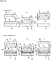
- the decorative piece material 91 is shaped as illustrated in FIGS. 13(a) to 13(c) (shaping step), and subsequently the shaped decorative piece material 91 is fusion-cut as illustrated in FIGS. 13(d) to 13(f) (fusion-cutting step).
- the first flat-plate die 20 used in the softening step in FIG. 2 is used, and the engraved die 24 with the fusion-cutting blades is used in place of the second flat-plate die 21.
- the engraved die 24 with the fusion-cutting blades is a die in which the recesses 26 of the design are formed and the fusion-cutting blades 25 are formed along the outlines of the design. While the decorative piece material 91 that is in the softened state due to the softening step is still placed on top of the first flat-plate die 20, the engraved die 24 with the fusion-cutting blades is brought closer to the first flat-plate die 20 as illustrated in FIG.
- the decorative piece material 91 is shaped in conformity with the recesses 26 of the engraved die 24 with the fusion-cutting blades. At this time, the decorative piece material 91 is partially fusion-cut by the fusion-cutting blades 25.
- the shaping step since the decorative piece material 91 that is softened in its entirety in advance is shaped, the shaping can be performed even when the decorative piece material 91 is thick.
- the decorative piece material 91 is held on the engraved die 24 with the fusion-cutting blades using gummed tape or the like, and in this state, the engraved die 24 with the fusion-cutting blades is moved upward as illustrated in FIG. 13(c) . Then, the procedure proceeds to the fusion-cutting step.
- the first flat-plate die 20 is replaced with a flat-plate die 27 with cushioning materials in which, as illustrated in FIG. 13(d) , cushioning material recesses 28 are formed at positions corresponding to respective portions of the design, the cushioning material recesses 28 being smaller than the respective portions of the design by about 0.3 mm to 1 mm, and cushioning materials 29 are arranged in the cushioning material recesses 28.
- the cushioning materials 29 may be made of cellular rubber, for example, and has such a thickness that the cushioning materials 29 protrude from the cushioning material recesses 28 for about 0.2 mm to 0.4 mm.
- the release paper 95 is disposed on the lower layer 93 side of the decorative piece material 91, on top of the flat-plate die 27 with the cushioning materials in FIG. 13(d) , with the double-sided tape 94 located on the upper side.
- the engraved die 24 with the fusion-cutting blades on which the decorative piece material 91 is held is brought closer to the flat-plate die 27 with the cushioning materials, and high-frequency dielectric heating is performed. Due to the repulsive force of the cushioning materials 29, the decorative piece material 91 is strongly pressed against and hence attached to the double-sided tape 94, and is also fusion-cut or cut by the fusion-cutting blades 25. Note that the release paper 95 is not cut by the fusion-cutting blades 25.
- a decorative piece 90 can be produced by performing the shaping and fusion-cutting step by replacing the dies after the softening step.
- the production device 10 shown in FIGS. 4 and 5 is used in which dies different from those of the first embodiment are mounted as the production device 10.
- the first flat-plate die 40 and a flat-plate die 44 with cushioning materials are mounted on the first slide plate 34.
- the flat-plate die 44 with the cushioning materials is a die in which cushioning material recesses 45 are formed at positions corresponding to and inward of respective portions of the design as described above and cushioning materials 46 are arranged in the cushioning material recesses 45.
- the second flat-plate die 60 shown in FIG. 16(a) and the second engraved die 64 with the fusion-cutting blades are mounted on the second slide plate 54.
- the design to be applied to the decorative piece 90 is "SUPER".
- the first jig 30 and the second jig 50 to which the dies 40 and 44 and the dies 60 and 64 are respectively mounted are fastened to a high-frequency dielectric heating device, which is not shown, such that the first jig 30 is located on the lower side and the second jig 50 is located on the upper side.
- the softening step (see FIG. 2 ) of softening the decorative piece material 91 is performed using the production device 10.
- the slide plates 34 and 54 are positioned such that the flat-plate dies 40 and 60 are located centrally, and the decorative piece material 91 is placed on top of the first flat-plate die 40 such that the upper layer 92 faces upward.
- the second jig 50 is moved downward, and while the decorative piece material 91 is thereby pressed, high-frequency dielectric heating is performed using the flat-plate dies 40 and 60 as electrodes, thereby softening and welding the entire decorative piece material 91.
- the second jig 50 is moved upward.
- the second slide plate 54 of the second jig 50 is slid, thereby moving the second engraved die 64 with the fusion-cutting blades to the center as illustrated in FIG. 18(b) .
- the second jig 50 is moved downward, and while the decorative piece material 91 is thereby pressed, high-frequency dielectric heating is performed using the first flat-plate die 40 and the second engraved die 64 with the fusion-cutting blades as electrodes (shaping step in FIGS. 13(a) to 13(c) ).
- the decorative piece material 91 Since the entire decorative piece material 91 is softened due to the softening step, the decorative piece material 91 is shaped in conformity with the recesses 65 of the second engraved die 64 with the fusion-cutting blades through high-frequency dielectric heating. Moreover, the decorative piece material 91 is partially fusion-cut by the fusion-cutting blades 66. After that, the decorative piece material 91 is cooled.
- the cooling may be performed through natural cooling, for example, or may be performed through water-cooling or the like of the dies or the like with use of a chiller in order to shorten the cooling time.
- the decorative piece material 91 is held on the second engraved die 64 with fusion-cutting blades using gummed tape or the like, and the second jig 50 is moved upward as illustrated in FIG. 18(b) .
- the first slide plate 34 of the first jig 30 is slid to the back side, thereby moving the flat-plate die 44 with the cushioning materials to the center (a portion indicated by the oblique lines in FIG. 14(a) ). Then, the double-sided tape 94 to which the release paper 95 is attached is placed on top of the flat-plate die 44 with the cushioning materials such that the release paper 95 is located on the lower side.
- the second jig 50 is moved downward, and while the decorative piece material 91 is thereby pressed, high-frequency dielectric heating is performed again using the flat-plate die 44 with the cushioning materials and the second engraved die 64 with the fusion-cutting blades as electrodes (fusion-cutting step in FIGS. 13(d) to 13(f) ).
- the cushioning materials 46 allow the decorative piece material 91 to be strongly attached to the double-sided tape 94, and the decorative piece material 91 and the double-sided tape 94 are fusion-cut by the fusion-cutting blades 66 along the outlines of the design by the fusion-cutting blades 66.
- the second jig 50 is moved upward, and the decorative piece material 91 is removed.
- the decorative piece material 91 can be removed from the production device 10 without positional displacement occurring. In this state, unnecessary portions are eliminated from the decorative piece material 91, and the application film 96 is attached to a surface of the decorative piece material 91 on the opposite side of the release paper 95. Thus, a decorative piece 90 can be obtained as illustrated in FIG. 18(d) .
- the obtained decorative piece 90 can be affixed to a product without positional displacement occurring, by peeling off the release paper 95, attaching the decorative piece 90 to the product via the double-sided tape 94, and then peeling off the application film 96.
- the slide plates 34 and 54 are respectively disposed in the first jig 30 and the second jig 50, and different types of dies are fastened to these slide plates 34 and 54. Therefore, replacement of the dies can be achieved simply by sliding the slide plates 34 and 54, and the softening step ( FIG. 2 ), the shaping step ( FIGS. 13(a) to 13(c) ), and the fusion-cutting step ( FIGS. 13(d) to 13(f) ) can be performed immediately one after another using the same device.
- the softening step allows the entire decorative piece material 91 to be softened in advance even when the decorative piece material 91 is thick
- the above-described embodiment is particularly preferable for the production of a bulky decorative piece 90 having a three-dimensional appearance and a sense of luxuriousness.
- a decorative piece material 91 that is 2.3 mm to 6 mm thick is used, a decorative piece 90 having a thickness of 2.5 mm to 6.2 mm can be produced.
- the dies of the foregoing first to third embodiments are not limited to those described above in the embodiments, and it is of course also possible to exchange the positions of the upper and lower dies, for example.
- the shape of the recesses of the dies any shapes, such as a mountain shape, a trapezoidal shape, and a round shape, and combinations of these shapes can be adopted.
- a plurality of dies are mounted to the first jig 30 and the second jig 50 in order to simplify the die replacement.
- the layer configurations, the materials, and the like of the decorative piece material 91 are given by way of example only, and it should be understood that various changes can be made thereto.
Landscapes
- Engineering & Computer Science (AREA)
- Mechanical Engineering (AREA)
- Lining Or Joining Of Plastics Or The Like (AREA)
- Laminated Bodies (AREA)
- Shaping Of Tube Ends By Bending Or Straightening (AREA)
Abstract
Description
- The present invention relates to a method and a device for producing a three-dimensional decorative piece made of a thermoplastic synthetic resin, such as an emblem to be attached to a car, a motorbike, a boat, a household electrical appliance, a game console, clothes, a bag, a cap, or the like, and more specifically relates to a method and a device with which a bulky three-dimensional decorative piece made of a thermoplastic synthetic resin can be produced.
- Three-dimensional decorative pieces made of a thermoplastic synthetic resin (hereinafter referred to simply as "decorative pieces", if appropriate), such as emblems, appliqués, and stickers, produced through high-frequency dielectric heating have been proposed (see Patent Document 1, for example).
- A decorative piece is produced from a decorative piece material that includes a thermoplastic resin sheet, a vapor-deposited metal layer, a foamed resin sheet, and the like. For example, according to Patent Document 1, while a decorative piece material is sandwiched between an engraved die and a flat-plate die, high-frequency dielectric heating is performed, thereby shaping the decorative piece material while heating and welding the material. The engraved die is provided with fusion-cutting blades along outlines of a design of a decorative piece to be produced, so that fusion-cutting can be performed simultaneously with shaping.
- [Patent Document 1] Japanese Patent No.
3235943 - In order to produce a decorative piece, it is necessary to soften, shape, and weld a decorative piece material by heating the decorative piece material through high-frequency dielectric heating. However, high-frequency dielectric heating has the property of radio waves being focused on a cutting edge, or a corner portion of a design. Accordingly, if the thickness of a decorative piece material is increased, it is no longer possible for the entire decorative piece material to be heated, and shaping and welding cannot be satisfactorily performed. For this reason, the thickness of decorative pieces that can be produced has been limited to up to about 2 mm.
- On the other hand, there is demand for bulky decorative pieces that have an enhanced three-dimensional appearance and an enhanced sense of luxuriousness.
- An object of the present invention is to provide a method and a device with which a bulky decorative piece made of a thermoplastic synthetic resin can be produced.
- A method for producing a three-dimensional decorative piece made of a thermoplastic synthetic resin according to the present invention includes:
- a step of preparing a decorative piece material including an upper layer that has a thermoplastic synthetic resin film and a lower layer that has a thermoplastic synthetic resin sheet;
- a step of disposing the decorative piece material on a flat-plate die serving as an electrode; and
- a softening step of softening and welding the decorative piece material by bringing a flat-plate die serving as another electrode closer to the flat-plate die serving as the electrode, and performing high-frequency dielectric heating while pressing the decorative piece material.
- The method can include:
- after the softening step,
- a step of disposing the decorative piece material on a flat-plate die serving as an electrode such that the lower layer side of the decorative piece material abuts against the flat-plate die;
- a shaping step of shaping the decorative piece material by bringing an engraved die, the engraved die serving as an electrode and having a recess of a design to be formed in the decorative piece material, closer to the flat-plate die on which the decorative piece material is disposed, and performing high-frequency dielectric heating while pressing the decorative piece material;
- a step of disposing a piece of release paper on the lower layer of the decorative piece material via a piece of double-sided tape or a thermal bonding film and disposing the decorative piece material on a flat-plate die serving as an electrode such that the release paper abuts against the flat-plate die; and
- a fusion-cutting step of bringing a fusion-cutting blade die closer to the flat-plate die, the fusion-cutting blade die serving as an electrode and having a recess of the design to be formed in the decorative piece material and a fusion-cutting blade provided along an outline of the design, and performing high-frequency dielectric heating while pressing the decorative piece material, to thereby fusion-cut the decorative piece material using the fusion-cutting blade.
- The method can include:
- after the softening step,
- a step of disposing a piece of release paper on the lower layer of the decorative piece material via a piece of double-sided tape or a thermal bonding film and disposing the decorative piece material on a flat-plate die serving as an electrode such that the release paper abuts against the flat-plate die; and
- a shaping and fusion-cutting step of bringing an engraved die with a fusion-cutting blade closer to the flat-plate die, the engraved die serving as an electrode and having a recess of a design to be formed in the decorative piece material and a fusion-cutting blade provided along an outline of the design, and performing high-frequency dielectric heating while pressing the decorative piece material, to thereby shape the decorative piece material and fusion-cut the decorative piece material using the fusion-cutting blade.
- The method can include:
- after the softening step,
- a step of disposing the decorative piece material on a flat-plate die serving as an electrode such that the lower layer of the decorative piece material abuts against the flat-plate die;
- a shaping step of shaping the decorative piece material by bringing an engraved die with a fusion-cutting blade, the engraved die serving as an electrode and having a recess of a design to be formed in the decorative piece material and a fusion bonding blade provided along an outline of the design, closer to the flat-plate die, and performing high-frequency dielectric heating while pressing the decorative piece material to such an extent that the decorative piece material is not fusion-cut; and
- a fusion-cutting step of, in a state in which the decorative piece material is held on the engraved die with the fusion-cutting blade, disposing a piece of release paper on the lower layer of the decorative piece material via a piece of double-sided tape or a thermal bonding film, bringing the engraved die with the fusion-cutting blade closer to a flat-plate die with a cushioning material, the flat-plate die serving as an electrode and having a recess formed at a position corresponding to the design and a cushioning material arranged in the recess, closere to the engraved die with the fusion-cutting blade, and performing high-frequency dielectric heating while pressing the decorative piece material, to thereby attach the decorative piece to the double-sided tape or weld the decorative piece material to the thermal bonding film and fusion-cut the decorative piece material using the fusion-cutting blade.
- The method can include:
- after the fusion-cutting step or the shaping and fusion-cutting step,
- a step of removing the decorative piece material, eliminating an unnecessary portion, and then attaching an application film for holding the separated design in position to the upper layer side of the decorative piece material.
- Moreover, a device for producing a three-dimensional decorative piece made of a thermoplastic synthetic resin according to the present invention is a device for producing a decorative piece made of a thermoplastic synthetic resin by shaping a decorative piece material including an upper layer that has a thermoplastic synthetic resin film and a lower layer that has a thermoplastic synthetic resin sheet through high-frequency dielectric heating and fusion-cutting the decorative piece material using a fusion-cutting blade, the device including:
- a first jig having a first frame that includes a pair of parallel first guide members, a first slide plate that is slidably disposed on the first guide members, and a first high-frequency dielectric heating device that is disposed on a transfer path of the first slide plate and applies high-frequency dielectric heating to the first slide plate; and
- a second jig having a second frame that includes a pair of parallel second guide members, a second slide plate that is slidably disposed on the second guide members, and a second high-frequency dielectric heating device that is disposed on a transfer path of the second slide plate and applies high-frequency dielectric heating to the second slide plate,
- wherein, in the first jig and the second jig, the first slide plate and the second slide plate are slidable in the same direction,
- the first high-frequency dielectric heating device and the second high-frequency dielectric heating device are arranged so as to oppose each other with the first slide plate and the second slide plate located therebetween,
- a first flat-plate die that is flat and a first engraved die with a fusion-cutting blade, the first engraved die having a recess of a design to be formed in the decorative piece material and a fusion-cutting blade along an outline of the design, are fastened to a surface of the first slide plate that opposes the second slide plate such that the first flat-plate die and the first engraved die are arranged side-by-side in a slide direction, and
- a second flat-plate die that is flat and a second engraved die, the second engraved die having a recess of the design to be formed in the decorative piece material, are fastened to a surface of the second slide plate that opposes the first slide plate such that the second flat-plate die and the second engraved die are arranged side-by-side in the slide direction.
- Moreover, a device for producing a three-dimensional decorative piece made of a thermoplastic synthetic resin according to the present invention is a device for producing a decorative piece made of a thermoplastic synthetic resin by shaping a decorative piece material including an upper layer that has a thermoplastic synthetic resin film and a lower layer that has a thermoplastic synthetic resin sheet through high-frequency dielectric heating and fusion-cutting the decorative piece material using a fusion-cutting blade, the device including:
- a first jig having a first frame, a first flat-plate die mounted on the first frame, and a first high-frequency dielectric heating device that applies high-frequency dielectric heating to the first flat-plate die; and
- a second jig having a second frame that includes a pair of parallel second guide members, a second slide plate that is slidably disposed on the second guide members, and a second high-frequency dielectric heating device that is disposed on a transfer path of the second slide plate and applies high-frequency dielectric heating to the second slide plate,
- wherein the first high-frequency dielectric heating device and the second high-frequency dielectric heating device are arranged so as to oppose each other with the first flat-plate die and the second slide plate located therebetween, and
- a second flat-plate die that is flat and a second engraved die with a fusion-cutting blade, the second engraved die having a recess of a design to be formed in the decorative piece material and a fusion-cutting blade along an outline of the design, are fastened to a surface of the second slide plate that opposes the first flat-plate die such that the second flat-plate die and the second engraved die are arranged side-by-side in the slide direction.
- Moreover, a device for producing a three-dimensional decorative piece made of a thermoplastic synthetic resin according to the present invention is a device for producing a decorative piece made of a thermoplastic synthetic resin by shaping a decorative piece material including an upper layer that has a thermoplastic synthetic resin film and a lower layer that has a thermoplastic synthetic resin sheet through high-frequency dielectric heating and fusion-cutting the decorative piece material using a fusion-cutting blade, the device including:
- a first jig having a first frame that includes a pair of parallel first guide members, a first slide plate that is slidably disposed on the first guide members, and a first high-frequency dielectric heating device that is disposed on a transfer path of the first slide plate and applies high-frequency dielectric heating to the first slide plate; and
- a second jig having a second frame that includes a pair of parallel second guide members, a second slide plate that is slidably disposed on the second guide members, and a second high-frequency dielectric heating device that is disposed on a transfer path of the second slide plate and applies high-frequency dielectric heating to the second slide plate,
- wherein, in the first jig and the second jig, the first slide plate and the second slide plate are slidable in the same direction,
- the first high-frequency dielectric heating device and the second high-frequency dielectric heating device are arranged so as to oppose each other with the first slide plate and the second slide plate located therebetween,
- a first flat-plate die that is flat and a recessed die with a cushioning material, the recessed die having a recess at a position corresponding to a design to be formed in the decorative piece material and a cushioning material fitted in the recess, are fastened to a surface of the first slide plate that opposes the second slide plate such that the first flat-plate die and the recessed die are arranged side-by-side in a slide direction, and
- a second flat-plate die that is flat and a second engraved die with a fusion-cutting blade, the second engraved die having a recess of the design to be formed in the decorative piece material and a fusion-cutting blade formed along an outline of the design, are fastened to a surface of the second slide plate that opposes the first slide plate such that the second flat-plate die and the second engraved die are arranged side-by-side in the slide direction.
- With the method for producing a three-dimensional decorative piece made of a thermoplastic synthetic resin according to the present invention, the entire decorative piece material can be heated and softened by performing high-frequency dielectric heating on the decorative piece material using the flat-plate dies. Since the entire decorative piece material is heated and softened through high-frequency dielectric heating prior to the shaping, the decorative piece material can be shaped using the engraved die in the subsequent shaping step even when the decorative piece material is thick, and thus, a bulky three-dimensional decorative piece made of a thermoplastic synthetic resin that has a three-dimensional appearance and a sense of luxuriousness can be favorably produced.
- Moreover, with the device for producing a three-dimensional decorative piece made of a thermoplastic synthetic resin according to the present invention, it is possible to shape the decorative piece material using the engraved die and/or the engraved die with the fusion-cutting blade immediately after softening the decorative piece material using the flat-plate die, by sliding the dies after the softening.
-
-
FIG. 1 is a cross-sectional view of a decorative piece material according to an embodiment of the present invention. -
FIG. 2 is an explanatory diagram illustrating a softening step of the present invention. -
FIG. 3 is an explanatory diagram illustrating a shaping step and a fusion-cutting step according to a first embodiment of the present invention. -
FIG. 4 shows (a) a plan view, (b) a vertical cross-sectional view, and (c) a horizontal cross-sectional view of a first jig that is used in the first embodiment of the present invention. -
FIG. 5 shows (a) a bottom view, (b) a vertical cross-sectional view, (c) a horizontal cross-sectional view, and (d) a plan view of a second jig that is used in the first embodiment of the present invention. -
FIG. 6 shows (a) a plan view, (b) a vertical cross-sectional view, and (c) a horizontal cross-sectional view of the first jig inFIG. 4 in a state in which dies are fastened to the first jig. -
FIG. 7 shows plan views and cross-sectional views of (a) a flat-plate die and (b) an engraved die with fusion-cutting blades that are to be fastened to the first jig. -
FIG. 8 shows (a) a bottom view, (b) a vertical cross-sectional view, and (c) a horizontal cross-sectional view of the second jig inFIG. 5 in a state in which dies are fastened to the second jig. -
FIG. 9 shows plan views and cross-sectional views of (a) a flat-plate die and (b) an engraved die that are to be fastened to the second jig. -
FIG. 10 is an explanatory diagram of a production method that uses a production device of the first embodiment of the present invention. -
FIG. 11 is an explanatory diagram illustrating a shaping and fusion-cutting step according to a second embodiment of the present invention. -
FIG. 12 is an explanatory diagram of a production method that uses a production device of the second embodiment of the present invention. -
FIG. 13 is an explanatory diagram illustrating a shaping step and a fusion-cutting step according to a third embodiment of the present invention. -
FIG. 14 shows (a) a plan view and (b) a vertical horizontal cross-sectional view of the first jig that is used in a third production method of the present invention. -
FIG. 15 shows a plan view and a cross-sectional view of a recessed die with cushioning materials that is to be fastened to the first jig inFIG. 14 . -
FIG. 16 shows (a) a bottom view and (b) a horizontal cross-sectional view of the second jig that is used in the third production method of the present invention. -
FIG. 17 shows a plan view and a cross-sectional view of an engraved die with fusion-cutting blades that is to be fastened to the second jig inFIG. 16 . -
FIG. 18 is an explanatory diagram of the production method that uses a third production device of the present invention. - Hereinafter, a three-dimensional
decorative piece 90 made of a thermoplastic synthetic resin of the present invention and a method for producing the three-dimensionaldecorative piece 90 will be described with reference to the drawings. Note that, in the drawings, the thicknesses of thedecorative piece 90 and layers of adecorative piece material 91, projections and recesses of dies, the thicknesses of the dies, and the like are shown exaggerated to facilitate the explanation. Also, the shapes, the designs, and the like of thedecorative piece 90 and thedecorative piece material 91 are given by way of example only, and can be changed as appropriate. -
FIG. 1 is a cross-sectional view of thedecorative piece material 91. As shown inFIG. 1 , thedecorative piece material 91 includes anupper layer 92 and alower layer 93. - The
upper layer 92 is a laminated film including a thermoplastic synthetic resin film that can be molded through high-frequency dielectric heating, a vapor-deposited metal layer, and the like. The thermoplastic synthetic resin film may be made of a soft thermoplastic synthetic resin, such as polyvinyl chloride or polyurethane, for example. Theupper layer 92 can be formed by, for example, forming the vapor-deposited metal layer on the thermoplastic synthetic resin film that is located on the upper surface side through metal vapor deposition. Note that theupper layer 92 may also have a configuration in which a migration preventing film is provided on a lower surface of the vapor-deposited metal layer via an adhesive layer, if necessary, and furthermore a thermoplastic synthetic resin film may be provided thereunder via an adhesive layer. - An example of the migration preventing film is an ethylene-vinyl alcohol copolymer (EVOH) film. The migration preventing film prevents a dye of a garment or the like to which the
decorative piece 90 is attached from migrating to a front surface side of thedecorative piece material 91. - A desired design can also be printed in a desired color onto an upper surface of the
upper layer 92 using a transparent color ink, a matte ink, a glossy ink, or the like. Furthermore, a fine line design can also be added by screen printing an ultraviolet-curable transparent UV ink or the like onto the above-described printing, so that a sense of luxuriousness such as that of braided embroidery, an aura of substance, elaborateness, a depth of color, and a metallic appearance, and furthermore, minute projections and depressions, and the like can also be expressed. - A soft sheet of a thermoplastic synthetic resin or a foamed resin sheet can be used as the
lower layer 93, and thelower layer 93 may be made of a thermoplastic synthetic resin, such as soft polyvinyl chloride (PVC), for example. - In the present invention, a material in which a foamed resin sheet or the like is thicker than that of a conventional material can be used as the
decorative piece material 91. For example, thedecorative piece material 91 may have a total thickness of greater than 2 mm, and the shaping of a decorative piece material having such a thickness has been difficult with a conventional method. Thedecorative piece material 91 has a thickness of preferably about 2.3 mm to 6 mm, but the present invention is also applicable to a decorative piece material having a greater thickness. - A feature of the present invention is that the
decorative piece material 91 is softened through high-frequency dielectric heating in advance, and then high-frequency dielectric heating is performed again to thereby perform shaping and fusion-cutting. - As illustrated in
FIG. 2 , the step of softening thedecorative piece material 91 can be performed by performing high-frequency dielectric heating while thedecorative piece material 91 is sandwiched between a first flat-plate die 20 and a second flat-plate die 21, which serve as electrodes. Specifically, thedecorative piece material 91 is placed on top of the first flat-plate die 20 as illustrated inFIG. 2(a) , the second flat-plate die 21 is brought closer to the first flat-plate die 20 as illustrated inFIG. 2(b) , and high-frequency dielectric heating is performed. Thus, insulators of theupper layer 92 and thelower layer 93 of thedecorative piece material 91 generate heat and fuse, allowing both layers to be softened in their entirety and welded to each other. After the high-frequency dielectric heating, the second flat-plate die 21 is separated from thedecorative piece material 91 as illustrated inFIG. 2(c) . - According to a first embodiment, after the softening step, the
decorative piece material 91 is shaped as illustrated inFIGS. 3(a) to 3(c) (shaping step), and subsequently the shapeddecorative piece material 91 is fusion-cut as illustrated inFIGS. 3(d) to 3(f) (fusion-cutting step). - In the shaping step, as illustrated in
FIG. 3(a) , the first flat-plate die 20 is used, and an engraveddie 22 is used in place of the second flat-plate die 21 inFIG. 2 . As illustrated inFIG. 3(a) , the engraveddie 22 is a die in which recesses 23 of a design to be formed in thedecorative piece material 91 are formed. While thedecorative piece material 91 that is in a softened state due to the softening step is still placed on top of the first flat-plate die 20, the engraveddie 22 is brought closer to the first flat-plate die 20 as illustrated inFIG. 3(b) , and high-frequency dielectric heating is performed. Thus, thedecorative piece material 91 is shaped in conformity with therecesses 23 of the engraved die 22 as illustrated inFIG. 3(c) . In the shaping step, since thedecorative piece material 91 that is softened in its entirety in advance is shaped, the shaping can be performed even when thedecorative piece material 91 is thick. Note that, after the shaping, thedecorative piece material 91 is cooled to fix its shape. - After the shaping step, the
decorative piece material 91 is fusion-cut along the design. In the fusion-cutting step, first, as illustrated inFIG. 3(d) , thedecorative piece material 91 with a piece ofrelease paper 95 disposed on or attached to thelower layer 93 side thereof via a piece of double-sided tape 94 is placed on top of the first flat-plate die 20. The double-sided tape 94 is used to attach the produceddecorative piece 90 to various products and the like. - In the fusion-cutting step, as also illustrated in
FIG. 3(d) , an engraveddie 24 with fusion-cuttings blade is used in place of the engraveddie 22. The engraved die 24 with the fusion-cutting blades is a die in which fusion-cuttingblades 25 are formed at peripheral edges ofrecesses 26 along outlines of the design to be formed in thedecorative piece material 91. If the fusion-cuttingblades 25 come into surface contact with thedecorative piece material 91 that has been shaped using the engraveddie 22, the dielectric heating efficiency decreases, resulting in a deformation or the like of the already shapeddecorative piece material 91. For this reason, it is desirable that, as illustrated inFIG. 3 , the fusion-cuttingblades 25 have a sharper angle than the engraved die 22 so as not to come into surface contact with thedecorative piece material 91. In a state in which thedecorative piece material 91 that has been shaped through the shaping step is placed on top of the first flat-plate die 20, with the double-sided tape 94 and therelease paper 95 disposed on or attached to thedecorative piece material 91, the engraved die 24 with the fusion-cutting blades is brought closer to the first flat-plate die 20 as illustrated inFIG. 3(e) , and high-frequency dielectric heating is performed. Thus, thedecorative piece material 91 and the double-sided tape 94 are fusion-cut or cut by the fusion-cuttingblades 25 as illustrated inFIG. 3(f) . Therelease paper 95 is not cut by the fusion-cuttingblades 25. - As a result of the above-described fusion-cutting step, the shaped and fusion-cut design and unnecessary portions of the
decorative piece material 91 remain on therelease paper 95 in a state in which the design and the unnecessary portions are separately attached to the double-sided tape 94. After that, the unnecessary portions are eliminated, and an application film is attached to theupper layer 92 side of thedecorative piece material 91 so as to prevent displacement of the design. Thus, adecorative piece 90 can be obtained. Examples of the application film include, but are not limited to, sheets in which an acrylic pressure-sensitive adhesive is applied to a polyester film or paper. - The obtained
decorative piece 90 can be affixed to a product by peeling off therelease paper 95 and attaching thedecorative piece 90 to the product via the double-sided tape 94 in a state in which the application film or the like is attached to thedecorative piece 90, and then peeling off the application film or the like. - According to the first embodiment of the present invention, a
decorative piece 90 can be produced by performing the shaping step and the fusion-cutting step by replacing the dies after the softening step. - As described above, replacement of the dies is needed when producing the
decorative piece 90. Hereinafter, aproduction device 10 with which adecorative piece 90 can be produced by favorably replacing the dies will be described. -
FIGS. 4 and5 show an example of theproduction device 10 that can be used in the present embodiment. Theproduction device 10 may be constituted by afirst jig 30 shown inFIG. 4 and asecond jig 50 shown inFIG. 5 . Thefirst jig 30 and thesecond jig 50 constitute theproduction device 10 in which, as shown inFIG. 10 , which will be described later, thefirst jig 30 is arranged on the lower side and thesecond jig 50 is arranged on the upper side. - In the
first jig 30, as shown inFIG. 4 , a rectangularfirst frame 32 is mounted on an upper surface of arectangular bottom plate 31. As shown inFIG. 4(c) , thefirst frame 32 includesfirst guide members 33 on an inner surface side thereof in a left-right direction, which is a width direction, thefirst guide members 33 extending parallel to each other. - A
first slide plate 34 is slidably engaged with thefirst guide members 33. Thefirst slide plate 34 has a length that is 2/3 of the length of the first frame 32 (first guide members 33). A plurality of tappedholes 35 to which a die, which will be described later, is to be fastened are formed in thefirst slide plate 34, and two dies can be mounted on thefirst slide plate 34 in a length direction. - Also, pin holes 37 for achieving alignment with the
second jig 50 are formed at a plurality of locations in thefirst frame 32. - Means for preventing displacement such as
magnets first frame 32 and thefirst slide plate 34, and when thefirst slide plate 34 is slid and abutted against thefirst frame 32, themagnets first slide plate 34 from moving freely. - The
first jig 30 is configured such that one wire (lower board) of a high-frequency molding machine, which is not shown, can be connected to the center of a lower surface of thebottom plate 31, and high-frequency dielectric heating is applied to a portion indicated by the oblique lines inFIG. 4 . The region that is subjected to the high-frequency dielectric heating is a region that occupies 1/2 of thefirst slide plate 34 in the length direction and 1/3 of thefirst frame 32 in the length direction and is located centrally in the length direction of thefirst frame 32. - Therefore, the
first jig 30 is configured such that, when thefirst slide plate 34 is slid in a direction indicated by the arrows inFIG. 4(a) , thefirst slide plate 34 can be slid to the front side, which is the lower side in the paper plane, as shown inFIGS. 4(a) and 4(b) and positioned by themagnets first slide plate 34 is slid to the back side, which is the upper side in the paper plane, as well, thefirst slide plate 34 can be positioned by themagnets - In the
second jig 50, as shown inFIG. 5 , a rectangularsecond frame 52 is mounted on a lower surface of a rectangulartop plate 51. Thesecond frame 52 includessecond guide members 53 on an inner surface side thereof in the left-right direction, which is the width direction, thesecond guide members 53 extending parallel to each other. Thesecond guide members 53 are formed so as to extend in the same direction as thefirst guide members 33. - A
second slide plate 54 is slidably engaged with thesecond guide members 53. Thesecond slide plate 54 has a length that is 2/3 of the length of the second frame 52 (second guide members 53). A plurality of tappedholes 55 to which a die, which will be described later, is to be fastened are formed in thesecond slide plate 54, and two dies can be mounted on thesecond slide plate 54 in the length direction. - Also, pin holes 57 for achieving alignment with the
first jig 30 are formed at a plurality of locations in thesecond frame 52. - Means for preventing displacement such as
magnets second frame 52 and thesecond slide plate 54, and when thesecond slide plate 54 is slid and abutted against thesecond frame 52, themagnets second slide plate 54 from moving freely. - In the
second jig 50, a cross-shaped bar 51a in which a plurality of screw holes are formed is mounted on an upper surface of thetop plate 51, so that thesecond jig 50 can be fastened to an upper board (not shown) of the high-frequency molding machine, which is not shown, using a bolt or the like. In thesecond jig 50, high-frequency dielectric heating is performed on a portion indicated by the oblique lines inFIG. 5 . The region that is subjected to the high-frequency dielectric heating is a region that occupies 1/2 of thesecond slide plate 54 in the length direction and 1/3 of thesecond frame 52 in the length direction and is located centrally in the length direction of thesecond frame 52. This region opposes the high-frequency dielectric heating region of thefirst jig 30 shown inFIG. 4 . - Therefore, the
second jig 50 is configured such that, when thesecond slide plate 54 is slid in a direction indicated by the arrows inFIG. 5(a) , thesecond slide plate 54 can be slid to the back side, which is the lower side in the paper plane, as shown inFIGS. 5(a) and 5(b) , and positioned by themagnets second slide plate 54 is slid to the front side, which is the upper side in the paper plane, as well, thesecond slide plate 54 can be positioned by themagnets - In the
first jig 30 and thesecond jig 50 described above, dies are mounted on thefirst slide plate 34 and thesecond slide plate 54. -
FIG. 6 shows thefirst jig 30 to which dies 40 and 41 are mounted, andFIG. 7 shows the dies 40 and 41 that are to be mounted to thefirst jig 30. The dies 40 and 41 can be mounted on thefirst slide plate 34 byfastening screws 36 to the tapped holes 35. The dies to be fastened to thefirst jig 30 may be the first flat-plate die 40 shown inFIG. 7(a) and the firstengraved die 41 with fusion-cutting blades shown inFIG. 7(b) . The first flat-plate die 40 is a die that has a flat upper surface, and the firstengraved die 41 with the fusion-cutting blades is a die in which fusion-cuttingblades 42 are formed along the outlines of the design of thedecorative piece material 91. -
FIG. 8 shows thesecond jig 50 to which dies 60 and 61 are mounted, andFIG. 9 shows the dies 60 and 61 that are to be mounted to thesecond jig 50. The dies 60 and 61 can be mounted on thesecond slide plate 54 byfastening screws 56 to the tapped holes 55. The dies to be fastened to thesecond jig 50 may be the second flat-plate die 60 shown inFIG. 9(a) and the secondengraved die 61 shown inFIG. 9(b) . The second flat-plate die 60 is a die that has a flat lower surface, and the secondengraved die 61 is a die in which recesses 62 of the design of thedecorative piece material 91 are formed. For example, recesses 62 that constitute inverted alphabet letters "CHRO" are formed in the secondengraved die 61 shown inFIG. 9 . - Then, the
first jig 30 and thesecond jig 50 on which the dies 40 and 41 and the dies 60 and 61 are respectively mounted are fastened to a high-frequency dielectric heating device, which is not shown, such that thefirst jig 30 is located on the lower side and thesecond jig 50 is located on the upper side. In order for thefirst jig 30 and thesecond jig 50 to be fastened correctly relative to each other in the vertical direction, the positions of both jigs are adjusted by inserting pins (not shown) into the pin holes 37 and 57. - Then, first, the softening step (see
FIG. 2 ) of softening thedecorative piece material 91 is performed using theproduction device 10. As illustrated inFIG. 10(a) , in both thefirst jig 30 and thesecond jig 50, theslide plates FIGS. 6 and8 ), and thedecorative piece material 91 is placed on top of the first flat-plate die 40. In this state, thesecond jig 50 is moved downward, and while thedecorative piece material 91 is thereby pressed, high-frequency dielectric heating is performed using the flat-plate dies 40 and 60 as electrodes, thereby softening and welding the entiredecorative piece material 91. When the softening is completed, thesecond jig 50 is moved upward. - Subsequently, with the
first jig 30 left as it is, thesecond slide plate 54 of thesecond jig 50 is slid to the back side, thereby moving the secondengraved die 61 to the center (the portion indicated by the oblique lines inFIG. 8 ) as illustrated inFIG. 10(b) . Then, thesecond jig 50 is moved downward, and while thedecorative piece material 91 is thereby pressed, high-frequency dielectric heating is performed using the first flat-plate die 40 and the secondengraved die 61 as electrodes (shaping step inFIGS. 3(a) to 3(c) ). Since the entiredecorative piece material 91 is softened due to the softening step, thedecorative piece material 91 is shaped in conformity with therecesses 62 of the secondengraved die 61 through high-frequency dielectric heating, and thus the design is formed therein as projections and recesses. When the shaping is completed, thedecorative piece material 91 is temporarily cooled to fix the shape. - Next, as illustrated in
FIG. 10(c) , thefirst slide plate 34 of thefirst jig 30 is slid to the back side, thereby moving the firstengraved die 41 with the fusion-cutting blades to the center (the portion indicated by the oblique lines inFIG. 6 ), and thesecond slide plate 54 of thesecond jig 50 is slid to the front side, thereby moving the second flat-plate die 60 to the center (the portion indicated by the oblique lines inFIG. 8 ). Then, thedecorative piece material 91 is disposed, with its surface that has served as the lower surface in the shaping step facing upward, such that the shaped design is fitted into the firstengraved die 41 with the fusion-cutting blades. The double-sided tape 94 to which therelease paper 95 is attached is placed on or attached to thedecorative piece material 91 from above such that therelease paper 95 is located on the upper side. In this state, thesecond jig 50 is moved downward, and while thedecorative piece material 91 is thereby pressed, high-frequency dielectric heating is performed using the firstengraved die 41 with the fusion-cutting blades and the second flat-plate die 60 as electrodes (fusion-cutting step inFIGS. 3(d) to 3(f) ). Thus, thedecorative piece material 91 and the double-sided tape 94 are fusion-cut along the outlines of the design by the fusion-cuttingblades 42. After that, thesecond jig 50 is moved upward, and thedecorative piece material 91 is removed. - Since the removed
decorative piece material 91 is attached to therelease paper 95 via the double-sided tape 94, thedecorative piece material 91 can be removed from theproduction device 10 without positional displacement occurring. In this state, unnecessary portions are eliminated from thedecorative piece material 91, and theapplication film 96 is attached to a surface of thedecorative piece material 91 on the opposite side to therelease paper 95. Thus, adecorative piece 90 can be obtained as illustrated inFIG. 10(d) . - The obtained
decorative piece 90 can be affixed to a product without positional displacement occurring, by peeling off therelease paper 95, attaching thedecorative piece 90 to the product via the double-sided tape 94, and then peeling off theapplication film 96. - In the above-described embodiment, the
slide plates first jig 30 and thesecond jig 50, and different types of dies are fastened to theseslide plates slide plates FIG. 2 ), the shaping step (FIGS. 3(a) to 3(c) ), and the fusion-cutting step (FIGS. 3(d) to 3(f) ) can be performed immediately one after another using the same device. - Moreover, since the softening step allows the entire
decorative piece material 91 to be softened in advance even when thedecorative piece material 91 is thick, the above-described embodiment is particularly preferable for the production of a bulkydecorative piece 90 having a three-dimensional appearance and a sense of luxuriousness. For example, if adecorative piece material 91 that is 2.3 mm to 6 mm thick is used, adecorative piece 90 having a thickness of 2.5 mm to 6.2 mm can be produced. - In a second embodiment, after the softening step, shaping and fusion-cutting are performed in one step. Note that, unless otherwise specified, the same reference numerals as those of the first embodiment denote the same or similar members, and a description thereof is omitted as appropriate.
- As is the case with the first embodiment, the
decorative piece material 91 is subjected to the softening step illustrated inFIG. 2 . - Then, the
decorative piece material 91 that is softened in its entirety is subjected to a shaping and fusion-cutting step illustrated inFIGS. 11(a) to 11(c) . The shaping and fusion-cutting step can be performed by performing high-frequency dielectric heating using the flat-plate die 20 on one hand and the engraved die 24 with the fusion-cutting blades, in which therecesses 26 of the design are formed and the fusion-cuttingblades 25 are formed along the outlines of the design, on the other hand. The engraved die 24 with the fusion-cutting blades shown inFIGS. 11(a) to 11(c) is a die in which therecesses 26 are formed to have a depth that is greater than the thickness of adecorative piece 90 to be obtained. - The engraved die 24 with the fusion-cutting blades is used in place of the second flat-plate die 21 used in the softening step (see
FIG. 2 ), and as illustrated inFIG. 11(a) , thedecorative piece material 91 that is in the softened state due to the softening step is placed on top of the flat-plate die 20, with therelease paper 95 disposed on thelower layer 93 side of thedecorative piece material 91, or attached to thedecorative piece material 91, via the double-sided tape 94. Then, as illustrated inFIG. 11(b) , the engraved die 24 with the fusion-cutting blades is brought closer to the flat-plate die 20, and high-frequency dielectric heating is performed. Thus, thedecorative piece material 91 is shaped as illustrated inFIG. 11(b) . In the present embodiment, since therecesses 26 of the engraved die 24 with the fusion-cutting blades are formed to have a depth that is greater than the thickness of thedecorative piece 90, a top portion of thedecorative piece 90 is shaped without abutting against a bottom surface of the die. As a result, adecorative piece 90 with a design having a slightly round-shaped curve can be obtained. Moreover, thedecorative piece material 91 is fusion-cut or cut together with the double-sided tape 94 by the fusion-cuttingblades 25 as illustrated inFIGS. 11(b) and 11(c) . - After that, unnecessary portions of the
decorative piece material 91 are eliminated, and theapplication film 96 is attached to theupper layer 92 side of thedecorative piece material 91 so as to prevent displacement of the design, and thus, adecorative piece 90 can be obtained. - According to the second embodiment of the present invention, a
decorative piece 90 can be produced by performing the shaping and fusion-cutting step by replacing the die after the softening step. - As described above, replacement of the die is needed when producing the
decorative piece 90. Hereinafter, aproduction device 10 with which adecorative piece 90 can be produced by favorably replacing the die will be described. - In the present embodiment, the
production device 10 shown inFIGS. 4 and5 is used in which dies different from those of the first embodiment are mounted as theproduction device 10. Specifically, in thefirst jig 30, as illustrated inFIGS. 12(a) and 12(b) , only the first flat-plate die 40 is mounted on thefirst slide plate 34, while in thesecond jig 50, the second flat-plate die 60 illustrated inFIG. 12(a) and a secondengraved die 64 with fusion-cutting blades are mounted on thesecond slide plate 54. Note that the secondengraved die 64 with the fusion-cutting blades hasrecesses 65 having a depth that is greater than the thickness of thedecorative piece 90 to be obtained, and includes fusion-cuttingblades 66 at peripheral edges of therecesses 65. - Then, the
first jig 30 and thesecond jig 50 to which thedie 40 and the dies 60 and 64 are respectively mounted are fastened to a high-frequency dielectric heating device, which is not shown, such that thefirst jig 30 is located on the lower side and thesecond jig 50 is located on the upper side. - Then, as is the case with the first embodiment, the softening step (see
FIG. 2 ) of softening thedecorative piece material 91 is performed using theproduction device 10. As illustrated inFIG. 12(a) , in both thefirst jig 30 and thesecond jig 50, theslide plates decorative piece material 91 is placed on top of the first flat-plate die 40. In this state, thesecond jig 50 is moved downward, and while thedecorative piece material 91 is thereby pressed, high-frequency dielectric heating is performed using the flat-plate dies 40 and 60 as electrodes, thereby softening and welding the entiredecorative piece material 91. When the softening is completed, thesecond jig 50 is moved upward. - Subsequently, with the
first jig 30 left as it is, thesecond slide plate 54 of thesecond jig 50 is slid, thereby moving the secondengraved die 64 with the fusion-cutting blades to the center as illustrated inFIG. 12(b) . Then, the double-sided tape 94 to which therelease paper 95 is attached is disposed on the first flat-plate die 40 of thefirst jig 30 or attached to thedecorative piece material 91, and thedecorative piece material 91 is placed thereon with theupper layer 92 facing upward. Subsequently, thesecond jig 50 is moved downward, and while thedecorative piece material 91 is thereby pressed, high-frequency dielectric heating is performed using the first flat-plate die 40 and the secondengraved die 64 with the fusion-cutting blades as electrodes (shaping step inFIGS. 11(a) to 11(c) ). Since the entiredecorative piece material 91 is softened due to the softening step, thedecorative piece material 91 is shaped within therecesses 65 of the secondengraved die 64 with the fusion-cutting blades through high-frequency dielectric heating, and thus, a design with a slightly round-shaped surface is formed. Moreover, thedecorative piece material 91 and the double-sided tape 94 are fusion-cut along the outlines of the design by the fusion-cuttingblades 66. After that, thesecond jig 50 is moved upward, and thedecorative piece material 91 is removed. - Since the removed
decorative piece material 91 is attached to therelease paper 95 via the double-sided tape 94, thedecorative piece material 91 can be removed from theproduction device 10 without positional displacement occurring. In this state, unnecessary portions are eliminated from thedecorative piece material 91, and theapplication film 96 is attached to a surface of thedecorative piece material 91 on the opposite side to therelease paper 95. Thus, adecorative piece 90 can be obtained as illustrated inFIG. 12(c) . - In the above-described
production device 10, theslide plates first jig 30 and thesecond jig 50, and different types of dies are fastened to theseslide plates first jig 30, the first flat-plate die 40 may be disposed non-slidably. - In the present embodiment as well, replacement of the die can be achieved simply by sliding the
second slide plate 54, and the softening step (FIG. 2 ), the shaping and fusion-cutting step (FIGS. 11(a) - 11 (c) ) can be performed immediately one after the other using the same device. - Moreover, since the softening step allows the entire
decorative piece material 91 to be softened in advance even when thedecorative piece material 91 is thick, the above-described embodiment is particularly preferable for the production of a bulkydecorative piece 90 having a three-dimensional appearance and a sense of luxuriousness. For example, if adecorative piece material 91 that is 2.3 mm to 6 mm thick is used, adecorative piece 90 having a thickness of 2.5 mm to 6.2 mm can be produced. - In a third embodiment, after the softening step, a shaping step and a fusion-cutting step are performed as is the case with the first embodiment. Note that, unless otherwise specified, the same reference numerals as those of the first embodiment and the second embodiment denote the same or similar members, and a description thereof is omitted as appropriate.
- As is the case with the first embodiment and the second embodiment, the
decorative piece material 91 is subjected to the softening step illustrated inFIG. 2 . - After the softening step, in the third embodiment, the
decorative piece material 91 is shaped as illustrated inFIGS. 13(a) to 13(c) (shaping step), and subsequently the shapeddecorative piece material 91 is fusion-cut as illustrated inFIGS. 13(d) to 13(f) (fusion-cutting step). - In the shaping step, as illustrated in
FIG. 13(a) , the first flat-plate die 20 used in the softening step inFIG. 2 is used, and the engraved die 24 with the fusion-cutting blades is used in place of the second flat-plate die 21. As illustrated inFIG. 13(a) , the engraved die 24 with the fusion-cutting blades is a die in which therecesses 26 of the design are formed and the fusion-cuttingblades 25 are formed along the outlines of the design. While thedecorative piece material 91 that is in the softened state due to the softening step is still placed on top of the first flat-plate die 20, the engraved die 24 with the fusion-cutting blades is brought closer to the first flat-plate die 20 as illustrated inFIG. 13(b) , and high-frequency dielectric heating is performed. Thus, thedecorative piece material 91 is shaped in conformity with therecesses 26 of the engraved die 24 with the fusion-cutting blades. At this time, thedecorative piece material 91 is partially fusion-cut by the fusion-cuttingblades 25. In the shaping step, since thedecorative piece material 91 that is softened in its entirety in advance is shaped, the shaping can be performed even when thedecorative piece material 91 is thick. After the shaping, thedecorative piece material 91 is held on the engraved die 24 with the fusion-cutting blades using gummed tape or the like, and in this state, the engraved die 24 with the fusion-cutting blades is moved upward as illustrated inFIG. 13(c) . Then, the procedure proceeds to the fusion-cutting step. - In the fusion-cutting step, the first flat-plate die 20 is replaced with a flat-plate die 27 with cushioning materials in which, as illustrated in
FIG. 13(d) , cushioning material recesses 28 are formed at positions corresponding to respective portions of the design, the cushioning material recesses 28 being smaller than the respective portions of the design by about 0.3 mm to 1 mm, andcushioning materials 29 are arranged in the cushioning material recesses 28. Thecushioning materials 29 may be made of cellular rubber, for example, and has such a thickness that thecushioning materials 29 protrude from the cushioning material recesses 28 for about 0.2 mm to 0.4 mm. - Then, as illustrated in
FIG. 13(d) , therelease paper 95 is disposed on thelower layer 93 side of thedecorative piece material 91, on top of the flat-plate die 27 with the cushioning materials inFIG. 13(d) , with the double-sided tape 94 located on the upper side. - Subsequently, as illustrated in
FIG. 13(e) , the engraved die 24 with the fusion-cutting blades on which thedecorative piece material 91 is held is brought closer to the flat-plate die 27 with the cushioning materials, and high-frequency dielectric heating is performed. Due to the repulsive force of thecushioning materials 29, thedecorative piece material 91 is strongly pressed against and hence attached to the double-sided tape 94, and is also fusion-cut or cut by the fusion-cuttingblades 25. Note that therelease paper 95 is not cut by the fusion-cuttingblades 25. - After that, unnecessary portions of the
decorative piece material 91 are eliminated, and theapplication film 96 is attached to theupper layer 92 side of thedecorative piece material 91 so as to prevent displacement of the design. Thus, adecorative piece 90 can be obtained. - According to the third embodiment of the present invention, a
decorative piece 90 can be produced by performing the shaping and fusion-cutting step by replacing the dies after the softening step. - As described above, replacement of the dies is needed when producing a
decorative piece 90. Hereinafter, aproduction device 10 with which adecorative piece 90 can be produced by favorably replacing the dies will be described. - In the present embodiment, the
production device 10 shown inFIGS. 4 and5 is used in which dies different from those of the first embodiment are mounted as theproduction device 10. Specifically, in thefirst jig 30, as illustrated inFIGS. 14(a) and 14(b) , the first flat-plate die 40 and a flat-plate die 44 with cushioning materials (seeFIG. 15 ) are mounted on thefirst slide plate 34. Note that the flat-plate die 44 with the cushioning materials is a die in which cushioning material recesses 45 are formed at positions corresponding to and inward of respective portions of the design as described above andcushioning materials 46 are arranged in the cushioning material recesses 45. In thesecond jig 50, the second flat-plate die 60 shown inFIG. 16(a) and the secondengraved die 64 with the fusion-cutting blades (seeFIG. 17 ) are mounted on thesecond slide plate 54. Moreover, in the present embodiment, the design to be applied to thedecorative piece 90 is "SUPER". - Then, the
first jig 30 and thesecond jig 50 to which the dies 40 and 44 and the dies 60 and 64 are respectively mounted are fastened to a high-frequency dielectric heating device, which is not shown, such that thefirst jig 30 is located on the lower side and thesecond jig 50 is located on the upper side. - Then, as is the case with the first embodiment, the softening step (see
FIG. 2 ) of softening thedecorative piece material 91 is performed using theproduction device 10. As illustrated inFIG. 18(a) , in both thefirst jig 30 and thesecond jig 50, theslide plates decorative piece material 91 is placed on top of the first flat-plate die 40 such that theupper layer 92 faces upward. In this state, thesecond jig 50 is moved downward, and while thedecorative piece material 91 is thereby pressed, high-frequency dielectric heating is performed using the flat-plate dies 40 and 60 as electrodes, thereby softening and welding the entiredecorative piece material 91. When the softening is completed, thesecond jig 50 is moved upward. - Subsequently, with the
first jig 30 left as it is, thesecond slide plate 54 of thesecond jig 50 is slid, thereby moving the secondengraved die 64 with the fusion-cutting blades to the center as illustrated inFIG. 18(b) . Then, thesecond jig 50 is moved downward, and while thedecorative piece material 91 is thereby pressed, high-frequency dielectric heating is performed using the first flat-plate die 40 and the secondengraved die 64 with the fusion-cutting blades as electrodes (shaping step inFIGS. 13(a) to 13(c) ). Since the entiredecorative piece material 91 is softened due to the softening step, thedecorative piece material 91 is shaped in conformity with therecesses 65 of the secondengraved die 64 with the fusion-cutting blades through high-frequency dielectric heating. Moreover, thedecorative piece material 91 is partially fusion-cut by the fusion-cuttingblades 66. After that, thedecorative piece material 91 is cooled. The cooling may be performed through natural cooling, for example, or may be performed through water-cooling or the like of the dies or the like with use of a chiller in order to shorten the cooling time. - In this state, the
decorative piece material 91 is held on the secondengraved die 64 with fusion-cutting blades using gummed tape or the like, and thesecond jig 50 is moved upward as illustrated inFIG. 18(b) . - Next, as illustrated in
FIG. 18(c) , thefirst slide plate 34 of thefirst jig 30 is slid to the back side, thereby moving the flat-plate die 44 with the cushioning materials to the center (a portion indicated by the oblique lines inFIG. 14(a) ). Then, the double-sided tape 94 to which therelease paper 95 is attached is placed on top of the flat-plate die 44 with the cushioning materials such that therelease paper 95 is located on the lower side. In this state, thesecond jig 50 is moved downward, and while thedecorative piece material 91 is thereby pressed, high-frequency dielectric heating is performed again using the flat-plate die 44 with the cushioning materials and the secondengraved die 64 with the fusion-cutting blades as electrodes (fusion-cutting step inFIGS. 13(d) to 13(f) ). Thecushioning materials 46 allow thedecorative piece material 91 to be strongly attached to the double-sided tape 94, and thedecorative piece material 91 and the double-sided tape 94 are fusion-cut by the fusion-cuttingblades 66 along the outlines of the design by the fusion-cuttingblades 66. After that, thesecond jig 50 is moved upward, and thedecorative piece material 91 is removed. - Since the removed
decorative piece material 91 is attached to therelease paper 95 via the double-sided tape 94, thedecorative piece material 91 can be removed from theproduction device 10 without positional displacement occurring. In this state, unnecessary portions are eliminated from thedecorative piece material 91, and theapplication film 96 is attached to a surface of thedecorative piece material 91 on the opposite side of therelease paper 95. Thus, adecorative piece 90 can be obtained as illustrated inFIG. 18(d) . - The obtained
decorative piece 90 can be affixed to a product without positional displacement occurring, by peeling off therelease paper 95, attaching thedecorative piece 90 to the product via the double-sided tape 94, and then peeling off theapplication film 96. - In the above-described embodiment, the
slide plates first jig 30 and thesecond jig 50, and different types of dies are fastened to theseslide plates slide plates FIG. 2 ), the shaping step (FIGS. 13(a) to 13(c) ), and the fusion-cutting step (FIGS. 13(d) to 13(f) ) can be performed immediately one after another using the same device. - Moreover, since the softening step allows the entire
decorative piece material 91 to be softened in advance even when thedecorative piece material 91 is thick, the above-described embodiment is particularly preferable for the production of a bulkydecorative piece 90 having a three-dimensional appearance and a sense of luxuriousness. For example, if adecorative piece material 91 that is 2.3 mm to 6 mm thick is used, adecorative piece 90 having a thickness of 2.5 mm to 6.2 mm can be produced. - The foregoing description is given merely to describe the present invention, and therefore should not be construed as limiting the invention recited in the appended claims or narrowing the scope of the present invention. Also, the constituent elements of the present invention are not limited to those described in the embodiments above, and it is of course possible to make various modifications within the technical scope defined in the appended claims.
- It is also possible to combine the dies of the foregoing first to third embodiments. Moreover, the types of the dies that are mounted to the
first jig 30 and thesecond jig 50 are not limited to those described above in the embodiments, and it is of course also possible to exchange the positions of the upper and lower dies, for example. Furthermore, regarding the shape of the recesses of the dies, any shapes, such as a mountain shape, a trapezoidal shape, and a round shape, and combinations of these shapes can be adopted. - In the embodiments, a plurality of dies are mounted to the
first jig 30 and thesecond jig 50 in order to simplify the die replacement. However, it is of course also possible to realize the present invention in a manner in which dies are replaced as appropriate, or dies are respectively mounted on a plurality of high-frequency induction heating devices. - In addition, the layer configurations, the materials, and the like of the
decorative piece material 91 are given by way of example only, and it should be understood that various changes can be made thereto. -
- 10
- Production device
- 20
- First flat-plate die
- 21
- Second flat-plate die
- 22
- Engraved die
- 24
- Engraved die with fusion-cutting blade
- 30
- First jig
- 34
- First slide plate
- 40
- First flat-plate die
- 41
- First engraved die with fusion-cutting blade
- 44
- Flat plate die with cushioning material
- 50
- Second jig
- 54
- Second slide plate
- 60
- Second flat-plate die
- 61
- Second engraved die
- 64
- Second engraved die with fusion-cutting blade
- 90
- Decorative piece
- 91
- Decorative piece material
Claims (8)
- A method for producing a decorative piece made of a thermoplastic synthetic resin, comprising:a step of preparing a decorative piece material including an upper layer that has a thermoplastic synthetic resin film and a lower layer that includes a thermoplastic synthetic resin sheet;a step of disposing the decorative piece material on a flat-plate die serving as an electrode; anda softening step of softening the decorative piece material by bringing a flat-plate die serving as another electrode closer to the flat-plate die serving as the electrode, and performing high-frequency dielectric heating while pressing the decorative piece material.
- The method for producing a decorative piece made of a thermoplastic synthetic resin according to claim 1, comprising:after the softening step,a step of disposing the decorative piece material on a flat-plate die serving as an electrode such that the lower layer side of the decorative piece material abuts against the flat-plate die;a shaping step of shaping the decorative piece material by bringing an engraved die, the engraved die serving as an electrode and having a recess of a design to be formed in the decorative piece material, closer to the flat-plate die on which the decorative piece material is disposed, and performing high-frequency dielectric heating while pressing the decorative piece material;a step of disposing a piece of release paper on the lower layer side of the decorative piece material via a piece of double-sided tape or a thermal bonding film and disposing the decorative piece material on a flat-plate die serving as an electrode such that the release paper abuts against the flat-plate die; anda fusion-cutting step of bringing a fusion-cutting blade die closer to the flat-plate die, the fusion-cutting blade die serving as an electrode and having a recess of the design to be formed in the decorative piece material and a fusion-cutting blade provided along an outline of the design, and performing high-frequency dielectric heating while pressing the decorative piece material, to thereby fusion-cut the decorative piece material using the fusion-cutting blade.
- The method for producing a decorative piece made of a thermoplastic synthetic resin according to claim 1, comprising:after the softening step,a step of disposing a piece of release paper on the lower layer side of the decorative piece material via a piece of double-sided tape or a thermal bonding film and disposing the decorative piece material on a flat-plate die serving as an electrode such that the release paper abuts against the flat-plate die; anda shaping and fusion-cutting step of bringing an engraved die with a fusion-cutting blade closer to the flat-plate die, the engraved die serving as an electrode and having a recess of a design to be formed in the decorative piece material and a fusion-cutting blade provided along an outline of the design, and performing high-frequency dielectric heating while pressing the decorative piece material, to thereby shape the decorative piece material and fusion-cut the decorative piece material using the fusion-cutting blade.
- The method for producing a decorative piece made of a thermoplastic synthetic resin according to claim 1, comprising:after the softening step,a step of disposing the decorative piece material on a flat-plate die serving as an electrode such that the lower layer side of the decorative piece material abuts against the flat-plate die;a shaping step of shaping the decorative piece material by bringing an engraved die with a fusion-cutting blade, the engraved die serving as an electrode and having a recess of a design to be formed in the decorative piece material and a fusion bonding blade provided along an outline of the design, closer to the flat-plate die, and performing high-frequency dielectric heating while pressing the decorative piece material to such an extent that the decorative piece material is not fusion-cut; anda fusion-cutting step of, in a state in which the decorative piece material is held on the engraved die with the fusion-cutting blade, disposing a piece of release paper on the lower layer side of the decorative piece material via a piece of double-sided tape or a thermal bonding film, bringing a flat-plate die with a cushioning material, the flat-plate die serving as an electrode and having a recess formed at a position corresponding to the design and a cushioning material arranged in the recess, closer to the engraved die with the fusion-cutting blade, and performing high-frequency dielectric heating while pressing the decorative piece material, to thereby attach the decorative piece to the double-sided tape or weld the decorative piece material to the thermal bonding film and fusion-cut the decorative piece material using the fusion-cutting blade.
- The method for producing a decorative piece made of a thermoplastic synthetic resin according to any one of claims 2 to 4, comprising:after the fusion-cutting step or the shaping and fusion-cutting step,a step of removing the decorative piece material, eliminating an unnecessary portion, and then attaching an application film for holding the separated design in position to the upper layer side of the decorative piece material.
- A device for producing a decorative piece made of a thermoplastic synthetic resin by shaping a decorative piece material including an upper layer that has a thermoplastic synthetic resin film and a lower layer that has a thermoplastic synthetic resin sheet through high-frequency dielectric heating and fusion-cutting the decorative piece material using a fusion-cutting blade, the device comprising:a first jig having a first frame that includes a pair of parallel first guide members, a first slide plate that is slidably disposed on the first guide members, and a first high-frequency dielectric heating device that is disposed on a transfer path of the first slide plate and applies high-frequency dielectric heating to the first slide plate; anda second jig having a second frame that includes a pair of parallel second guide members, a second slide plate that is slidably disposed on the second guide members, and a second high-frequency dielectric heating device that is disposed on a transfer path of the second slide plate and applies high-frequency dielectric heating to the second slide plate,wherein, in the first jig and the second jig, the first slide plate and the second slide plate are slidable in the same direction,the first high-frequency dielectric heating device and the second high-frequency dielectric heating device are arranged so as to oppose each other with the first slide plate and the second slide plate located therebetween,a first flat-plate die that is flat and a first engraved die with a fusion-cutting blade, the first engraved die having a recess of a design to be formed in the decorative piece material and a fusion-cutting blade along an outline of the design, are fastened to a surface of the first slide plate that opposes the second slide plate such that the first flat-plate die and the first engraved die are arranged side-by-side in a slide direction, anda second flat-plate die that is flat and a second engraved die, the second engraved die having a recess of the design to be formed in the decorative piece material, are fastened to a surface of the second slide plate that opposes the first slide plate such that the second flat-plate die and the second engraved die are arranged side-by-side in the slide direction.
- A device for producing a decorative piece made of a thermoplastic synthetic resin by shaping a decorative piece material including an upper layer that has a thermoplastic synthetic resin film and a lower layer that has a thermoplastic synthetic resin sheet through high-frequency dielectric heating and fusion-cutting the decorative piece material using a fusion-cutting blade, the device comprising:a first jig having a first frame, a first flat-plate die mounted on the first frame, and a first high-frequency dielectric heating device that applies high-frequency dielectric heating to the first flat-plate die; anda second jig having a second frame that includes a pair of parallel second guide members, a second slide plate that is slidably disposed on the second guide members, and a second high-frequency dielectric heating device that is disposed on a transfer path of the second slide plate and applies high-frequency dielectric heating to the second slide plate,wherein the first high-frequency dielectric heating device and the second high-frequency dielectric heating device are arranged so as to oppose each other with the first flat-plate die and the second slide plate located therebetween, anda second flat-plate die that is flat and a second engraved die with a fusion-cutting blade, the second engraved die having a recess of a design to be formed in the decorative piece material and a fusion-cutting blade along an outline of the design, are fastened to a surface of the second slide plate that opposes the first flat-plate die such that the second flat-plate die and the second engraved die are arranged side-by-side in the slide direction.
- A device for producing a decorative piece made of a thermoplastic synthetic resin by shaping a decorative piece material including an upper layer that has a thermoplastic synthetic resin film and a lower layer that has a thermoplastic synthetic resin sheet through high-frequency dielectric heating and fusion-cutting the decorative piece material using a fusion-cutting blade, the device comprising:a first jig having a first frame that includes a pair of parallel first guide members, a first slide plate that is slidably disposed on the first guide members, and a first high-frequency dielectric heating device that is disposed on a transfer path of the first slide plate and applies high-frequency dielectric heating to the first slide plate; anda second jig having a second frame that includes a pair of parallel second guide members, a second slide plate that is slidably disposed on the second guide members, and a second high-frequency dielectric heating device that is disposed on a transfer path of the second slide plate and applies high-frequency dielectric heating to the second slide plate,wherein, in the first jig and the second jig, the first slide plate and the second slide plate are slidable in the same direction,the first high-frequency dielectric heating device and the second high-frequency dielectric heating device are arranged so as to oppose each other with the first slide plate and the second slide plate located therebetween,a first flat-plate die that is flat and a recessed die with a cushioning material, the recessed die having a recess at a position corresponding to a design to be formed in the decorative piece material and a cushioning material fitted in the recess, are fastened to a surface of the first slide plate that opposes the second slide plate such that the first flat-plate die and the recessed die are arranged side-by-side in a slide direction, anda second flat-plate die that is flat and a second engraved die with a fusion-cutting blade, the second engraved die having a recess of the design to be formed in the decorative piece material and a fusion-cutting blade formed along an outline of the design, are fastened to a surface of the second slide plate that opposes the first slide plate such that the second flat-plate die and the second engraved die are arranged side-by-side in the slide direction.
Applications Claiming Priority (1)
| Application Number | Priority Date | Filing Date | Title |
|---|---|---|---|
| PCT/JP2018/017109 WO2019207746A1 (en) | 2018-04-27 | 2018-04-27 | Production method and production device for stereoscopic decoration piece made of thermoplastic synthetic resin |
Publications (3)
| Publication Number | Publication Date |
|---|---|
| EP3683041A1 true EP3683041A1 (en) | 2020-07-22 |
| EP3683041A4 EP3683041A4 (en) | 2021-06-23 |
| EP3683041B1 EP3683041B1 (en) | 2025-02-12 |
Family
ID=66092516
Family Applications (1)
| Application Number | Title | Priority Date | Filing Date |
|---|---|---|---|
| EP18916678.8A Active EP3683041B1 (en) | 2018-04-27 | 2018-04-27 | Production method and production device for stereoscopic decoration piece made of thermoplastic synthetic resin |
Country Status (6)
| Country | Link |
|---|---|
| US (1) | US11718043B2 (en) |
| EP (1) | EP3683041B1 (en) |
| JP (1) | JP6496884B1 (en) |
| CN (1) | CN111356577B (en) |
| MX (1) | MX2020005991A (en) |
| WO (1) | WO2019207746A1 (en) |
Families Citing this family (4)
| Publication number | Priority date | Publication date | Assignee | Title |
|---|---|---|---|---|
| WO2020217264A1 (en) * | 2019-04-22 | 2020-10-29 | 剛司 黒田 | Production method and production device for three-dimensional thermoplastic synthetic resin emblem |
| JP6727563B1 (en) * | 2019-10-31 | 2020-07-22 | 株式会社信和商会 | Notch forming device for fasteners |
| JP6765155B1 (en) * | 2020-04-03 | 2020-10-07 | 株式会社信和商会 | Mold for forming a notch in a fastener and a notch forming device for a fastener |
| CN115320110B (en) * | 2022-08-22 | 2025-10-21 | 杭州中村锯业机械有限公司 | Production process of water-cooling vest |
Family Cites Families (11)
| Publication number | Priority date | Publication date | Assignee | Title |
|---|---|---|---|---|
| US3126307A (en) * | 1957-03-12 | 1964-03-24 | Method of sealing thermoplastic materials by dielectric heating | |
| JP3223308B2 (en) * | 1993-03-04 | 2001-10-29 | 静岡県 | Decoration method for wood and wood materials |
| JP3235943B2 (en) | 1995-02-06 | 2001-12-04 | 黒田 暢夫 | Method for producing decorative piece made of thermoplastic synthetic resin sheet |
| CN1154293A (en) * | 1996-01-12 | 1997-07-16 | 普乐士企业有限公司 | Molding method of thermoplastic synthetic resin film marker |
| JP2000279556A (en) * | 1999-03-30 | 2000-10-10 | Mizuno Corp | Racket decoration |
| KR101196530B1 (en) | 2004-03-30 | 2012-11-01 | 다이니폰 인사츠 가부시키가이샤 | Sheet for Decoration Simultaneous with Injection Molding and Decorated Resin Molding |
| JP4227587B2 (en) * | 2004-11-11 | 2009-02-18 | 黒田 暢夫 | Three-dimensional decorative piece made of synthetic resin and its manufacturing method |
| WO2011151904A1 (en) * | 2010-06-02 | 2011-12-08 | 黒田 暢夫 | Production method and production device for stereoscopic decoration piece made of thermoplastic synthetic resin |
| TW201332745A (en) * | 2012-02-02 | 2013-08-16 | Chenming Mold Ind Corp | Heat pressure molding method |
| JP5917462B2 (en) * | 2013-08-12 | 2016-05-18 | 黒田 暢夫 | Three-dimensional decorative piece made of thermoplastic synthetic resin and manufacturing method thereof |
| US10384398B2 (en) * | 2014-05-02 | 2019-08-20 | Nobuo Kuroda | Device and method for manufacturing emblem with incorporated IC chip |
-
2018
- 2018-04-27 EP EP18916678.8A patent/EP3683041B1/en active Active
- 2018-04-27 MX MX2020005991A patent/MX2020005991A/en unknown
- 2018-04-27 JP JP2018553259A patent/JP6496884B1/en active Active
- 2018-04-27 US US16/756,096 patent/US11718043B2/en active Active
- 2018-04-27 CN CN201880072171.1A patent/CN111356577B/en active Active
- 2018-04-27 WO PCT/JP2018/017109 patent/WO2019207746A1/en not_active Ceased
Also Published As
| Publication number | Publication date |
|---|---|
| EP3683041A4 (en) | 2021-06-23 |
| JP6496884B1 (en) | 2019-04-10 |
| MX2020005991A (en) | 2020-08-17 |
| JPWO2019207746A1 (en) | 2020-05-07 |
| US11718043B2 (en) | 2023-08-08 |
| EP3683041B1 (en) | 2025-02-12 |
| WO2019207746A1 (en) | 2019-10-31 |
| CN111356577A (en) | 2020-06-30 |
| CN111356577B (en) | 2022-03-15 |
| US20210187864A1 (en) | 2021-06-24 |
Similar Documents
| Publication | Publication Date | Title |
|---|---|---|
| US11718043B2 (en) | Production method and production device for three-dimensional decorative piece made of thermoplastic synthetic resin | |
| US20130068376A1 (en) | Method and apparatus for producing three-dimensional decoration piece made of thermoplastic synthetic resin | |
| EP3733427A1 (en) | Thermoplastic synthetic resin three-dimensional decorative piece and manufacturing method therefor | |
| US12576578B2 (en) | Three-dimensional decorative piece and method of producing the same | |
| CA3061921C (en) | Method and apparatus for producing three-dimensional emblem made of thermoplastic synthetic resin | |
| EP3138695B1 (en) | Device and method for manufacturing emblem with incorporated ic chip | |
| JP5613356B1 (en) | Fabric decoration structure and fabric decoration method | |
| CN115279599A (en) | Method for producing thermoplastic synthetic resin decorative sheet | |
| KR100621995B1 (en) | Three-dimensional sheet production method and three-dimensional sheet produced by | |
| JP6419379B2 (en) | Method for manufacturing an emblem made of a thermoplastic synthetic resin in which an IC chip is incorporated | |
| KR20160109199A (en) | Synthetic resin formed pattern on it and manufacturing method of thereof | |
| JPS6232098A (en) | Method of forming one-point-shaped mark | |
| JP3161939U (en) | Sheet work | |
| KR102031085B1 (en) | Volume transfer foil and manufacturing method thereof | |
| JP2016168718A (en) | Resin molded product and production method thereof | |
| JP2009096112A (en) | Three-dimensional card, three-dimensional card forming method, and embossing machine for forming three-dimensional card |
Legal Events
| Date | Code | Title | Description |
|---|---|---|---|
| STAA | Information on the status of an ep patent application or granted ep patent |
Free format text: STATUS: THE INTERNATIONAL PUBLICATION HAS BEEN MADE |
|
| PUAI | Public reference made under article 153(3) epc to a published international application that has entered the european phase |
Free format text: ORIGINAL CODE: 0009012 |
|
| STAA | Information on the status of an ep patent application or granted ep patent |
Free format text: STATUS: REQUEST FOR EXAMINATION WAS MADE |
|
| 17P | Request for examination filed |
Effective date: 20200430 |
|
| AK | Designated contracting states |
Kind code of ref document: A1 Designated state(s): AL AT BE BG CH CY CZ DE DK EE ES FI FR GB GR HR HU IE IS IT LI LT LU LV MC MK MT NL NO PL PT RO RS SE SI SK SM TR |
|
| AX | Request for extension of the european patent |
Extension state: BA ME |
|
| A4 | Supplementary search report drawn up and despatched |
Effective date: 20210521 |
|
| RIC1 | Information provided on ipc code assigned before grant |
Ipc: B29C 65/04 20060101AFI20210517BHEP Ipc: B44C 3/02 20060101ALI20210517BHEP Ipc: B32B 37/06 20060101ALI20210517BHEP Ipc: B32B 38/18 20060101ALI20210517BHEP |
|
| DAV | Request for validation of the european patent (deleted) | ||
| DAX | Request for extension of the european patent (deleted) | ||
| P01 | Opt-out of the competence of the unified patent court (upc) registered |
Effective date: 20230530 |
|
| STAA | Information on the status of an ep patent application or granted ep patent |
Free format text: STATUS: EXAMINATION IS IN PROGRESS |
|
| 17Q | First examination report despatched |
Effective date: 20240417 |
|
| GRAP | Despatch of communication of intention to grant a patent |
Free format text: ORIGINAL CODE: EPIDOSNIGR1 |
|
| STAA | Information on the status of an ep patent application or granted ep patent |
Free format text: STATUS: GRANT OF PATENT IS INTENDED |
|
| INTG | Intention to grant announced |
Effective date: 20241112 |
|
| GRAS | Grant fee paid |
Free format text: ORIGINAL CODE: EPIDOSNIGR3 |
|
| GRAA | (expected) grant |
Free format text: ORIGINAL CODE: 0009210 |
|
| STAA | Information on the status of an ep patent application or granted ep patent |
Free format text: STATUS: THE PATENT HAS BEEN GRANTED |
|
| AK | Designated contracting states |
Kind code of ref document: B1 Designated state(s): AL AT BE BG CH CY CZ DE DK EE ES FI FR GB GR HR HU IE IS IT LI LT LU LV MC MK MT NL NO PL PT RO RS SE SI SK SM TR |
|
| REG | Reference to a national code |
Ref country code: GB Ref legal event code: FG4D |
|
| REG | Reference to a national code |
Ref country code: CH Ref legal event code: EP |
|
| REG | Reference to a national code |
Ref country code: DE Ref legal event code: R096 Ref document number: 602018079195 Country of ref document: DE |
|
| REG | Reference to a national code |
Ref country code: IE Ref legal event code: FG4D |
|
| REG | Reference to a national code |
Ref country code: NL Ref legal event code: MP Effective date: 20250212 |
|
| PG25 | Lapsed in a contracting state [announced via postgrant information from national office to epo] |
Ref country code: RS Free format text: LAPSE BECAUSE OF FAILURE TO SUBMIT A TRANSLATION OF THE DESCRIPTION OR TO PAY THE FEE WITHIN THE PRESCRIBED TIME-LIMIT Effective date: 20250512 |
|
| PG25 | Lapsed in a contracting state [announced via postgrant information from national office to epo] |
Ref country code: FI Free format text: LAPSE BECAUSE OF FAILURE TO SUBMIT A TRANSLATION OF THE DESCRIPTION OR TO PAY THE FEE WITHIN THE PRESCRIBED TIME-LIMIT Effective date: 20250212 |
|
| PG25 | Lapsed in a contracting state [announced via postgrant information from national office to epo] |
Ref country code: PL Free format text: LAPSE BECAUSE OF FAILURE TO SUBMIT A TRANSLATION OF THE DESCRIPTION OR TO PAY THE FEE WITHIN THE PRESCRIBED TIME-LIMIT Effective date: 20250212 |
|
| PG25 | Lapsed in a contracting state [announced via postgrant information from national office to epo] |
Ref country code: ES Free format text: LAPSE BECAUSE OF FAILURE TO SUBMIT A TRANSLATION OF THE DESCRIPTION OR TO PAY THE FEE WITHIN THE PRESCRIBED TIME-LIMIT Effective date: 20250212 |
|
| REG | Reference to a national code |
Ref country code: LT Ref legal event code: MG9D |
|
| PG25 | Lapsed in a contracting state [announced via postgrant information from national office to epo] |
Ref country code: IS Free format text: LAPSE BECAUSE OF FAILURE TO SUBMIT A TRANSLATION OF THE DESCRIPTION OR TO PAY THE FEE WITHIN THE PRESCRIBED TIME-LIMIT Effective date: 20250612 Ref country code: NO Free format text: LAPSE BECAUSE OF FAILURE TO SUBMIT A TRANSLATION OF THE DESCRIPTION OR TO PAY THE FEE WITHIN THE PRESCRIBED TIME-LIMIT Effective date: 20250512 |
|
| PG25 | Lapsed in a contracting state [announced via postgrant information from national office to epo] |
Ref country code: NL Free format text: LAPSE BECAUSE OF FAILURE TO SUBMIT A TRANSLATION OF THE DESCRIPTION OR TO PAY THE FEE WITHIN THE PRESCRIBED TIME-LIMIT Effective date: 20250212 |
|
| PG25 | Lapsed in a contracting state [announced via postgrant information from national office to epo] |
Ref country code: HR Free format text: LAPSE BECAUSE OF FAILURE TO SUBMIT A TRANSLATION OF THE DESCRIPTION OR TO PAY THE FEE WITHIN THE PRESCRIBED TIME-LIMIT Effective date: 20250212 |
|
| PG25 | Lapsed in a contracting state [announced via postgrant information from national office to epo] |
Ref country code: PT Free format text: LAPSE BECAUSE OF FAILURE TO SUBMIT A TRANSLATION OF THE DESCRIPTION OR TO PAY THE FEE WITHIN THE PRESCRIBED TIME-LIMIT Effective date: 20250612 Ref country code: LV Free format text: LAPSE BECAUSE OF FAILURE TO SUBMIT A TRANSLATION OF THE DESCRIPTION OR TO PAY THE FEE WITHIN THE PRESCRIBED TIME-LIMIT Effective date: 20250212 |
|
| PG25 | Lapsed in a contracting state [announced via postgrant information from national office to epo] |
Ref country code: GR Free format text: LAPSE BECAUSE OF FAILURE TO SUBMIT A TRANSLATION OF THE DESCRIPTION OR TO PAY THE FEE WITHIN THE PRESCRIBED TIME-LIMIT Effective date: 20250513 Ref country code: BG Free format text: LAPSE BECAUSE OF FAILURE TO SUBMIT A TRANSLATION OF THE DESCRIPTION OR TO PAY THE FEE WITHIN THE PRESCRIBED TIME-LIMIT Effective date: 20250212 |
|
| REG | Reference to a national code |
Ref country code: AT Ref legal event code: MK05 Ref document number: 1765705 Country of ref document: AT Kind code of ref document: T Effective date: 20250212 |
|
| PG25 | Lapsed in a contracting state [announced via postgrant information from national office to epo] |
Ref country code: SE Free format text: LAPSE BECAUSE OF FAILURE TO SUBMIT A TRANSLATION OF THE DESCRIPTION OR TO PAY THE FEE WITHIN THE PRESCRIBED TIME-LIMIT Effective date: 20250212 |
|
| PG25 | Lapsed in a contracting state [announced via postgrant information from national office to epo] |
Ref country code: SM Free format text: LAPSE BECAUSE OF FAILURE TO SUBMIT A TRANSLATION OF THE DESCRIPTION OR TO PAY THE FEE WITHIN THE PRESCRIBED TIME-LIMIT Effective date: 20250212 |
|
| PG25 | Lapsed in a contracting state [announced via postgrant information from national office to epo] |
Ref country code: DK Free format text: LAPSE BECAUSE OF FAILURE TO SUBMIT A TRANSLATION OF THE DESCRIPTION OR TO PAY THE FEE WITHIN THE PRESCRIBED TIME-LIMIT Effective date: 20250212 |
|
| PG25 | Lapsed in a contracting state [announced via postgrant information from national office to epo] |
Ref country code: AT Free format text: LAPSE BECAUSE OF FAILURE TO SUBMIT A TRANSLATION OF THE DESCRIPTION OR TO PAY THE FEE WITHIN THE PRESCRIBED TIME-LIMIT Effective date: 20250212 |
|
| PG25 | Lapsed in a contracting state [announced via postgrant information from national office to epo] |
Ref country code: EE Free format text: LAPSE BECAUSE OF FAILURE TO SUBMIT A TRANSLATION OF THE DESCRIPTION OR TO PAY THE FEE WITHIN THE PRESCRIBED TIME-LIMIT Effective date: 20250212 Ref country code: CZ Free format text: LAPSE BECAUSE OF FAILURE TO SUBMIT A TRANSLATION OF THE DESCRIPTION OR TO PAY THE FEE WITHIN THE PRESCRIBED TIME-LIMIT Effective date: 20250212 |
|
| PG25 | Lapsed in a contracting state [announced via postgrant information from national office to epo] |
Ref country code: RO Free format text: LAPSE BECAUSE OF FAILURE TO SUBMIT A TRANSLATION OF THE DESCRIPTION OR TO PAY THE FEE WITHIN THE PRESCRIBED TIME-LIMIT Effective date: 20250212 |
|
| PG25 | Lapsed in a contracting state [announced via postgrant information from national office to epo] |
Ref country code: SK Free format text: LAPSE BECAUSE OF FAILURE TO SUBMIT A TRANSLATION OF THE DESCRIPTION OR TO PAY THE FEE WITHIN THE PRESCRIBED TIME-LIMIT Effective date: 20250212 |
|
| REG | Reference to a national code |
Ref country code: DE Ref legal event code: R097 Ref document number: 602018079195 Country of ref document: DE |
|
| REG | Reference to a national code |
Ref country code: CH Ref legal event code: H13 Free format text: ST27 STATUS EVENT CODE: U-0-0-H10-H13 (AS PROVIDED BY THE NATIONAL OFFICE) Effective date: 20251125 |
|
| PG25 | Lapsed in a contracting state [announced via postgrant information from national office to epo] |
Ref country code: LU Free format text: LAPSE BECAUSE OF NON-PAYMENT OF DUE FEES Effective date: 20250427 |
|
| PLBE | No opposition filed within time limit |
Free format text: ORIGINAL CODE: 0009261 |
|
| STAA | Information on the status of an ep patent application or granted ep patent |
Free format text: STATUS: NO OPPOSITION FILED WITHIN TIME LIMIT |
|
| PG25 | Lapsed in a contracting state [announced via postgrant information from national office to epo] |
Ref country code: MC Free format text: LAPSE BECAUSE OF FAILURE TO SUBMIT A TRANSLATION OF THE DESCRIPTION OR TO PAY THE FEE WITHIN THE PRESCRIBED TIME-LIMIT Effective date: 20250212 |
|
| REG | Reference to a national code |
Ref country code: BE Ref legal event code: MM Effective date: 20250430 |
|
| PG25 | Lapsed in a contracting state [announced via postgrant information from national office to epo] |
Ref country code: BE Free format text: LAPSE BECAUSE OF NON-PAYMENT OF DUE FEES Effective date: 20250430 |
|
| PG25 | Lapsed in a contracting state [announced via postgrant information from national office to epo] |
Ref country code: CH Free format text: LAPSE BECAUSE OF NON-PAYMENT OF DUE FEES Effective date: 20250430 |
|
| 26N | No opposition filed |
Effective date: 20251113 |
|
| PG25 | Lapsed in a contracting state [announced via postgrant information from national office to epo] |
Ref country code: IE Free format text: LAPSE BECAUSE OF NON-PAYMENT OF DUE FEES Effective date: 20250427 |
|
| PG25 | Lapsed in a contracting state [announced via postgrant information from national office to epo] |
Ref country code: CY Free format text: LAPSE BECAUSE OF FAILURE TO SUBMIT A TRANSLATION OF THE DESCRIPTION OR TO PAY THE FEE WITHIN THE PRESCRIBED TIME-LIMIT Effective date: 20250212 |
|
| PG25 | Lapsed in a contracting state [announced via postgrant information from national office to epo] |
Ref country code: LT Free format text: LAPSE BECAUSE OF FAILURE TO SUBMIT A TRANSLATION OF THE DESCRIPTION OR TO PAY THE FEE WITHIN THE PRESCRIBED TIME-LIMIT Effective date: 20250212 |
|
| PGFP | Annual fee paid to national office [announced via postgrant information from national office to epo] |
Ref country code: GB Payment date: 20260423 Year of fee payment: 9 |
|
| PGFP | Annual fee paid to national office [announced via postgrant information from national office to epo] |
Ref country code: IT Payment date: 20260427 Year of fee payment: 9 |
|
| PGFP | Annual fee paid to national office [announced via postgrant information from national office to epo] |
Ref country code: DE Payment date: 20260422 Year of fee payment: 9 |
|
| PGFP | Annual fee paid to national office [announced via postgrant information from national office to epo] |
Ref country code: FR Payment date: 20260420 Year of fee payment: 9 |