EP3682997A1 - Resistance spot welding method - Google Patents
Resistance spot welding method Download PDFInfo
- Publication number
- EP3682997A1 EP3682997A1 EP18856855.4A EP18856855A EP3682997A1 EP 3682997 A1 EP3682997 A1 EP 3682997A1 EP 18856855 A EP18856855 A EP 18856855A EP 3682997 A1 EP3682997 A1 EP 3682997A1
- Authority
- EP
- European Patent Office
- Prior art keywords
- current passage
- content
- formula
- subsequent
- passage
- Prior art date
- Legal status (The legal status is an assumption and is not a legal conclusion. Google has not performed a legal analysis and makes no representation as to the accuracy of the status listed.)
- Granted
Links
- 238000003466 welding Methods 0.000 title claims abstract description 45
- 238000000034 method Methods 0.000 title claims description 21
- 229910000831 Steel Inorganic materials 0.000 claims abstract description 57
- 239000010959 steel Substances 0.000 claims abstract description 57
- 238000001816 cooling Methods 0.000 claims abstract description 16
- 239000000203 mixture Substances 0.000 claims description 16
- 239000000126 substance Substances 0.000 claims description 15
- 230000000052 comparative effect Effects 0.000 description 29
- 230000007423 decrease Effects 0.000 description 11
- 238000005204 segregation Methods 0.000 description 8
- 238000009864 tensile test Methods 0.000 description 8
- 238000011156 evaluation Methods 0.000 description 7
- 230000000694 effects Effects 0.000 description 5
- 238000010586 diagram Methods 0.000 description 4
- 230000002349 favourable effect Effects 0.000 description 4
- 230000015572 biosynthetic process Effects 0.000 description 3
- 230000005494 condensation Effects 0.000 description 2
- 238000009833 condensation Methods 0.000 description 2
- 238000002474 experimental method Methods 0.000 description 2
- 239000012535 impurity Substances 0.000 description 2
- 238000007711 solidification Methods 0.000 description 2
- 230000008023 solidification Effects 0.000 description 2
- 230000003068 static effect Effects 0.000 description 2
- KZEVSDGEBAJOTK-UHFFFAOYSA-N 1-(2,4,6,7-tetrahydrotriazolo[4,5-c]pyridin-5-yl)-2-[5-[2-[[3-(trifluoromethoxy)phenyl]methylamino]pyrimidin-5-yl]-1,3,4-oxadiazol-2-yl]ethanone Chemical compound N1N=NC=2CN(CCC=21)C(CC=1OC(=NN=1)C=1C=NC(=NC=1)NCC1=CC(=CC=C1)OC(F)(F)F)=O KZEVSDGEBAJOTK-UHFFFAOYSA-N 0.000 description 1
- HMUNWXXNJPVALC-UHFFFAOYSA-N 1-[4-[2-(2,3-dihydro-1H-inden-2-ylamino)pyrimidin-5-yl]piperazin-1-yl]-2-(2,4,6,7-tetrahydrotriazolo[4,5-c]pyridin-5-yl)ethanone Chemical compound C1C(CC2=CC=CC=C12)NC1=NC=C(C=N1)N1CCN(CC1)C(CN1CC2=C(CC1)NN=N2)=O HMUNWXXNJPVALC-UHFFFAOYSA-N 0.000 description 1
- VWVRASTUFJRTHW-UHFFFAOYSA-N 2-[3-(azetidin-3-yloxy)-4-[2-(2,3-dihydro-1H-inden-2-ylamino)pyrimidin-5-yl]pyrazol-1-yl]-1-(2,4,6,7-tetrahydrotriazolo[4,5-c]pyridin-5-yl)ethanone Chemical compound O=C(CN1C=C(C(OC2CNC2)=N1)C1=CN=C(NC2CC3=C(C2)C=CC=C3)N=C1)N1CCC2=C(C1)N=NN2 VWVRASTUFJRTHW-UHFFFAOYSA-N 0.000 description 1
- LPZOCVVDSHQFST-UHFFFAOYSA-N 2-[4-[2-(2,3-dihydro-1H-inden-2-ylamino)pyrimidin-5-yl]-3-ethylpyrazol-1-yl]-1-(2,4,6,7-tetrahydrotriazolo[4,5-c]pyridin-5-yl)ethanone Chemical compound C1C(CC2=CC=CC=C12)NC1=NC=C(C=N1)C=1C(=NN(C=1)CC(=O)N1CC2=C(CC1)NN=N2)CC LPZOCVVDSHQFST-UHFFFAOYSA-N 0.000 description 1
- WZFUQSJFWNHZHM-UHFFFAOYSA-N 2-[4-[2-(2,3-dihydro-1H-inden-2-ylamino)pyrimidin-5-yl]piperazin-1-yl]-1-(2,4,6,7-tetrahydrotriazolo[4,5-c]pyridin-5-yl)ethanone Chemical compound C1C(CC2=CC=CC=C12)NC1=NC=C(C=N1)N1CCN(CC1)CC(=O)N1CC2=C(CC1)NN=N2 WZFUQSJFWNHZHM-UHFFFAOYSA-N 0.000 description 1
- JQMFQLVAJGZSQS-UHFFFAOYSA-N 2-[4-[2-(2,3-dihydro-1H-inden-2-ylamino)pyrimidin-5-yl]piperazin-1-yl]-N-(2-oxo-3H-1,3-benzoxazol-6-yl)acetamide Chemical compound C1C(CC2=CC=CC=C12)NC1=NC=C(C=N1)N1CCN(CC1)CC(=O)NC1=CC2=C(NC(O2)=O)C=C1 JQMFQLVAJGZSQS-UHFFFAOYSA-N 0.000 description 1
- JVKRKMWZYMKVTQ-UHFFFAOYSA-N 2-[4-[2-(2,3-dihydro-1H-inden-2-ylamino)pyrimidin-5-yl]pyrazol-1-yl]-N-(2-oxo-3H-1,3-benzoxazol-6-yl)acetamide Chemical compound C1C(CC2=CC=CC=C12)NC1=NC=C(C=N1)C=1C=NN(C=1)CC(=O)NC1=CC2=C(NC(O2)=O)C=C1 JVKRKMWZYMKVTQ-UHFFFAOYSA-N 0.000 description 1
- 229910001209 Low-carbon steel Inorganic materials 0.000 description 1
- 238000004364 calculation method Methods 0.000 description 1
- ZTXONRUJVYXVTJ-UHFFFAOYSA-N chromium copper Chemical compound [Cr][Cu][Cr] ZTXONRUJVYXVTJ-UHFFFAOYSA-N 0.000 description 1
- 239000012141 concentrate Substances 0.000 description 1
- 238000010276 construction Methods 0.000 description 1
- 238000007796 conventional method Methods 0.000 description 1
- 238000009795 derivation Methods 0.000 description 1
- 238000002844 melting Methods 0.000 description 1
- 230000008018 melting Effects 0.000 description 1
- 230000035515 penetration Effects 0.000 description 1
- 238000010008 shearing Methods 0.000 description 1
- 230000002195 synergetic effect Effects 0.000 description 1
Images

Classifications
-
- B—PERFORMING OPERATIONS; TRANSPORTING
- B23—MACHINE TOOLS; METAL-WORKING NOT OTHERWISE PROVIDED FOR
- B23K—SOLDERING OR UNSOLDERING; WELDING; CLADDING OR PLATING BY SOLDERING OR WELDING; CUTTING BY APPLYING HEAT LOCALLY, e.g. FLAME CUTTING; WORKING BY LASER BEAM
- B23K11/00—Resistance welding; Severing by resistance heating
- B23K11/10—Spot welding; Stitch welding
- B23K11/11—Spot welding
- B23K11/115—Spot welding by means of two electrodes placed opposite one another on both sides of the welded parts
-
- B—PERFORMING OPERATIONS; TRANSPORTING
- B23—MACHINE TOOLS; METAL-WORKING NOT OTHERWISE PROVIDED FOR
- B23K—SOLDERING OR UNSOLDERING; WELDING; CLADDING OR PLATING BY SOLDERING OR WELDING; CUTTING BY APPLYING HEAT LOCALLY, e.g. FLAME CUTTING; WORKING BY LASER BEAM
- B23K11/00—Resistance welding; Severing by resistance heating
- B23K11/16—Resistance welding; Severing by resistance heating taking account of the properties of the material to be welded
-
- C—CHEMISTRY; METALLURGY
- C22—METALLURGY; FERROUS OR NON-FERROUS ALLOYS; TREATMENT OF ALLOYS OR NON-FERROUS METALS
- C22C—ALLOYS
- C22C38/00—Ferrous alloys, e.g. steel alloys
-
- C—CHEMISTRY; METALLURGY
- C22—METALLURGY; FERROUS OR NON-FERROUS ALLOYS; TREATMENT OF ALLOYS OR NON-FERROUS METALS
- C22C—ALLOYS
- C22C38/00—Ferrous alloys, e.g. steel alloys
- C22C38/04—Ferrous alloys, e.g. steel alloys containing manganese
-
- C—CHEMISTRY; METALLURGY
- C22—METALLURGY; FERROUS OR NON-FERROUS ALLOYS; TREATMENT OF ALLOYS OR NON-FERROUS METALS
- C22C—ALLOYS
- C22C38/00—Ferrous alloys, e.g. steel alloys
- C22C38/14—Ferrous alloys, e.g. steel alloys containing titanium or zirconium
-
- B—PERFORMING OPERATIONS; TRANSPORTING
- B23—MACHINE TOOLS; METAL-WORKING NOT OTHERWISE PROVIDED FOR
- B23K—SOLDERING OR UNSOLDERING; WELDING; CLADDING OR PLATING BY SOLDERING OR WELDING; CUTTING BY APPLYING HEAT LOCALLY, e.g. FLAME CUTTING; WORKING BY LASER BEAM
- B23K2103/00—Materials to be soldered, welded or cut
- B23K2103/02—Iron or ferrous alloys
- B23K2103/04—Steel or steel alloys
-
- B—PERFORMING OPERATIONS; TRANSPORTING
- B23—MACHINE TOOLS; METAL-WORKING NOT OTHERWISE PROVIDED FOR
- B23K—SOLDERING OR UNSOLDERING; WELDING; CLADDING OR PLATING BY SOLDERING OR WELDING; CUTTING BY APPLYING HEAT LOCALLY, e.g. FLAME CUTTING; WORKING BY LASER BEAM
- B23K2103/00—Materials to be soldered, welded or cut
- B23K2103/08—Non-ferrous metals or alloys
- B23K2103/15—Magnesium or alloys thereof
Definitions
- the present disclosure relates to a resistance spot welding method.
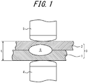
- resistance spot welding is a technique whereby a sheet combination (parts to be welded) 3 of two or more overlapping steel sheets (a two-sheet combination of a lower steel sheet 1 and an upper steel sheet 2 in the drawing) is squeezed by a pair of upper and lower electrodes (a lower electrode 4 and an upper electrode 5) and, while applying an electrode force, a current is passed to melt a contact portion and form a nugget 6 of a required size, thus obtaining a weld joint.
- t is the thickness of the sheet combination 3.
- the quality of the weld joint obtained in this way is evaluated based on nugget diameter and penetration, shear tensile strength (strength when a tensile test is performed in the shearing direction of the joint), cross tension strength (strength when a tensile test is performed in the peeling direction of the joint), fatigue strength, etc.
- static strengths such as shear tensile strength and cross tension strength are very important as indices of joint quality.
- the shear tensile strength tends to increase with an increase in the tensile strength of the base steel sheet.
- the cross tension strength tends to hardly increase but rather decrease with an increase in the tensile strength of the base steel sheet.
- JP S58-003792 A (PTL 1) and JP S58-003793 A (PTL 2) each disclose a resistance spot welding method of, after performing main current passage to form a nugget, further performing current passage (subsequent current passage) to soften the nugget.
- JP WO 2013-161937 A1 discloses a welding method of, after performing current passage in spot welding, solidifying the nugget edges and then passing a current through the nugget under predetermined conditions to heat the nugget, in order to suppress segregation of embrittlement elements such as P and S at the nugget edges.
- One of the disclosed embodiments is a resistance spot welding method of joining parts to be welded that are two or more overlapping steel sheets, wherein a steel sheet whose Mn content is highest of the overlapping steel sheets has a chemical composition that satisfies 0.050 % ⁇ C ⁇ 0.250 %, 3.50 % ⁇ Mn ⁇ 12.00 %, 0.001 % ⁇ Si ⁇ 2.000 %, 0.001 % ⁇ P ⁇ 0.025 %, and 0.0001 % ⁇ S ⁇ 0.0020 %, the resistance spot welding method comprises performing main current passage and subsequent current passage, with a cooling time of 0.01 s or more being provided between the main current passage and the subsequent current passage, and Ip/I which is a ratio of a current value of the subsequent current passage to a current value of the main current passage satisfies, depending on a constant A defined by the Mn content and P content in the chemical composition, any of the following Formulas (1) to (3) in relation to Tp, T, and the constant
- Resistance spot welding composed of main current passage and subsequent current passage was performed using sheet combinations of two overlapping steel sheets while varying Mn content and P content, to produce various weld joints.
- the ratio of the current value of the subsequent current passage to the current value of the main current passage denoted by Ip/I, was varied.
- a cooling time of 0.1 s was provided between the main current passage and the subsequent current passage, and the welding time in the main current passage and the welding time in the subsequent current passage were respectively 0.4 s and 0.2 s.
- the electrode force was constant (3.5 kN).
- the fracture form is plug failure, and the plug diameter is 100 % or more and less than 110 % of the formed nugget diameter.
- FIG. 2 illustrates the evaluation results, with the horizontal axis representing Mn content and the vertical axis representing Ip/I.
- the constant A is derived from any of the foregoing Formulas (4) to (6) depending on the Mn content of a steel sheet having the highest Mn content (hereafter also simply referred to as "steel sheet”) of the steel sheets constituting the parts to be welded, as described above.
- the reason why the method of deriving the constant A needs to be changed depending on the Mn content of the steel sheet is presumed as follows.
- the constant A is defined by the Mn content and the P content of the steel sheet as indicated in the foregoing Formulas (4) to (6), and technically expresses the influence of each of the Mn content and the P content on the decrease of the toughness of the nugget. Since the influence of P tends to be promoted by an increase in the Mn content as mentioned earlier, the constant A needs to be set so that the influence of Mn relatively increases in association with an increase in the Mn content. Hence, the method of deriving the constant A needs to be changed depending on the Mn content of the steel sheet.
- the reason why the constant A is set based on the steel sheet having the highest Mn content of the steel sheets constituting the parts to be welded is that the composition of the nugget is influenced by the steel sheet having the highest Mn content.
- the lower limit of the foregoing Formula (1) is preferably (0.45 + A) ⁇ (1 + T)/(1 + Tp), and more preferably (0.49 + A) ⁇ (1 + T)/(1 + Tp).
- the upper limit of the foregoing Formula (1) is preferably (1.94 - A) ⁇ (1 + T)/(1 + Tp), and more preferably (1.84 - A) ⁇ (1 + T)/(1 + Tp).
- the lower limit of the foregoing Formula (2) is preferably (0.442 + 1.2 ⁇ A) ⁇ (1 + T)/(1 + Tp), and more preferably (0.482 + 1.2 ⁇ A) ⁇ (1 + T)/(1 + Tp).
- the upper limit of the foregoing Formula (2) is preferably (1.98 - 2 ⁇ A) ⁇ (1 + T)/(1 + Tp), and more preferably (1.88 - 2 ⁇ A) ⁇ (1 + T)/(1 + Tp).
- the lower limit of the foregoing Formula (3) is preferably (0.433 + 1.3 ⁇ A) ⁇ (1 + T)/(1 + Tp), and more preferably (0.473 + 1.3 ⁇ A) ⁇ (1 + T)/(1 + Tp).
- the upper limit of the foregoing Formula (3) is preferably (2.07 - 3 ⁇ A) ⁇ (1 + T)/(1 + Tp), and more preferably (1.97 - 3 ⁇ A) ⁇ (1 + T)/(1 + Tp).
- a cooling time of 0.01 s (seconds) or more (preferably 0.04 s to 0.5 s) needs to be provided between the main current passage and the subsequent current passage. If the cooling time is long, however, the nugget temperature at the start of the subsequent current passage decreases. Hence, the welding conditions of the subsequent current passage need to be adjusted depending on the cooling time, and the relationship of T and Tp needs to be incorporated in the foregoing Formulas (1) to (3).
- the welding time of the main current passage and the welding time of the subsequent current passage are preferably 0.2 s to 1.5 s and 0.04 s to 1.0 s, respectively.
- both the main current passage and the subsequent current passage are preferably performed by constant current control, and the current value is preferably selected in a range of 4.0 kA to 15.0 kA.
- the electrode force is preferably 2.0 kN to 7.0 kN.
- the main current passage and the subsequent current passage may use the same electrode force or different electrode forces.
- preliminary current passage may be performed before the main current passage, or upslope current passage in which current is gradually increased may be performed.
- the main current passage may be performed in two or more steps with a welding interval for cooling being provided therebetween, or the main current passage may be made up of multiple steps that vary in the current value during the current passage.
- the current value of the subsequent current passage is determined using, as the current value of the main current passage, the current value of current passage that plays a prominent role in nugget formation.
- the combination of the welding interval and the subsequent current passage after the main current passage may be repeatedly performed a plurality of times. If the number of repetitions is excessively large, however, the welding time increases and the construction workability decreases. Accordingly, the number of repetitions is desirably 9 or less.
- Any welding device that includes a pair of upper and lower electrodes and is capable of freely controlling each of the electrode force and the welding current during welding may be used in the resistance spot welding method according to one of the disclosed embodiments.
- the force mechanism air cylinder, servomotor, etc.
- the type stationary, robot gun, etc.
- the electrode shape, and the like are not limited.
- the resistance spot welding method according to one of the disclosed embodiments can be used effectively.
- the Mn content is preferably 4.50 % or more, more preferably 4.80 % or more, and further preferably 5.00 % or more.
- the welding method according to one of the disclosed embodiments is more effective in such cases.
- the chemical composition may contain, besides the foregoing components, one or more selected from the group consisting of Ti: 0.001 % to 0.200 %, Al: 0.001 % to 0.200 %, B: 0.0001 % to 0.0020 %, and N: 0.0010 % to 0.0100 %.
- the balance other than these components consists of Fe and inevitable impurities.
- the chemical composition of each steel sheet as the other part(s) to be welded is not limited, and steel sheets having various strengths from mild steel to ultra high tensile strength steel may be used. A plurality of steel sheets having the same chemical composition may be used as steel sheets included in the sheet combination.
- each steel sheet is not limited, and is preferably 0.8 mm to 2.3 mm.
- the thickness of the sheet combination is not limited, and is preferably 1.6 mm to 6.0 mm.
- the resistance spot welding method according to one of the disclosed embodiments may also be used for a sheet combination of three or more overlapping steel sheets.
- the balance other than the components in Table 1 consists of Fe and inevitable impurities.
- An inverter DC resistance spot welder was used as the welder, and chromium copper electrodes with 6 mm face diameter DR-shaped tips were used as the electrodes.
- the fracture form was plug failure. In all Examples, the nugget diameter was sufficient, and no expulsion occurred. In all Comparative Examples, on the other hand, the fracture form was partial plug failure or plug failure (interface failure), and favorable fracture form was not obtained.
Landscapes
- Engineering & Computer Science (AREA)
- Mechanical Engineering (AREA)
- Chemical & Material Sciences (AREA)
- Materials Engineering (AREA)
- Metallurgy (AREA)
- Organic Chemistry (AREA)
- Resistance Welding (AREA)
Abstract
Description
- The present disclosure relates to a resistance spot welding method.
- As illustrated in
FIG. 1 , resistance spot welding is a technique whereby a sheet combination (parts to be welded) 3 of two or more overlapping steel sheets (a two-sheet combination of a lower steel sheet 1 and an upper steel sheet 2 in the drawing) is squeezed by a pair of upper and lower electrodes (alower electrode 4 and an upper electrode 5) and, while applying an electrode force, a current is passed to melt a contact portion and form anugget 6 of a required size, thus obtaining a weld joint. In the drawing, t is the thickness of thesheet combination 3. - The quality of the weld joint obtained in this way is evaluated based on nugget diameter and penetration, shear tensile strength (strength when a tensile test is performed in the shearing direction of the joint), cross tension strength (strength when a tensile test is performed in the peeling direction of the joint), fatigue strength, etc. In particular, static strengths such as shear tensile strength and cross tension strength are very important as indices of joint quality.
- Of the static strengths, the shear tensile strength tends to increase with an increase in the tensile strength of the base steel sheet. Meanwhile, the cross tension strength tends to hardly increase but rather decrease with an increase in the tensile strength of the base steel sheet.
- One reason for this is presumed to be that toughness decreases due to hardening of the nugget and solidification segregation of P and S. Another reason is presumed to be that plastic deformation is suppressed due to hardening of the nugget and the heat-affected zone (HAZ) and as a result opening stress concentrates at the nugget edges.
- To solve these problems, for example,
JP S58-003792 A JP S58-003793 A - JP
WO 2013-161937 A1 (PTL 3) discloses a welding method of, after performing current passage in spot welding, solidifying the nugget edges and then passing a current through the nugget under predetermined conditions to heat the nugget, in order to suppress segregation of embrittlement elements such as P and S at the nugget edges. -
- PTL 1:
JP S58-003792 A - PTL 2:
JP S58-003793 A - PTL 3: JP
WO 2013-161937 A1 - In recent years, studies have been made to use steel sheets containing a larger amount of Mn than before, in response to demand for stronger and thinner automotive parts.
- With the welding methods disclosed in PTL 1 to
PTL 3, however, when a steel sheet containing a large amount of Mn is used as a part to be welded, favorable fracture form may not be obtained in a cross tensile test. The welding methods need improvement in this point. - It could therefore be helpful to provide a resistance spot welding method that achieves favorable fracture form in a cross tensile test even in the case where a steel sheet containing a large amount of Mn is used as a part to be welded.
- We conducted intensive studies to achieve the object stated above.
- First, we performed resistance spot welding using, as parts to be welded, steel sheets with various Mn contents and P contents, and investigated why favorable fracture form cannot be obtained in the case where a steel sheet containing a large amount of Mn is used as a part to be welded.
- We consequently learned that, not only with steel sheets having high P content but also with steel sheets having high Mn content, brittle interface failure occurs at the nugget in the cross tensile test. As a result of closely looking into why an increase in the Mn content causes interface failure, we learned that there are synergistic effects of condensation of Mn resulting from solidification after welding, formation of a brittle portion associated with the condensation of Mn, and promotion of the influence of segregation of P (P is an embrittlement element) by an increase in Mn content.
- We further conducted studies to prevent such interface failure, and discovered that, by performing main current passage and subsequent current passage with a cooling time of at least predetermined duration between the main current passage and the subsequent current passage and appropriately controlling the ratio of the current value of the subsequent current passage to the current value of the main current passage depending on the welding time of the subsequent current passage, the cooling time, and the Mn content and the P content of a steel sheet as a part to be welded, formation of a brittle portion at the nugget edges can be suppressed to prevent brittle interface failure even in the case where a steel sheet containing a large amount of Mn is used as a part to be welded.
- The present disclosure is based on these discoveries and further studies.
- We thus provide:
- 1. A resistance spot welding method of joining parts to be welded that are two or more overlapping steel sheets, wherein a steel sheet whose Mn content is highest of the overlapping steel sheets has a chemical composition that satisfies
0.050 % ≤ C ≤ 0.250 %,
3.50 % ≤ Mn ≤ 12.00 %,
0.001 % ≤ Si ≤ 2.000 %,
0.001 % ≤ P ≤ 0.025 %, and
0.0001 % ≤ S ≤ 0.0020 %,
the resistance spot welding method comprises performing main current passage and subsequent current passage, with a cooling time of 0.01 s or more being provided between the main current passage and the subsequent current passage, and Ip/I which is a ratio of a current value of the subsequent current passage to a current value of the main current passage satisfies, depending on a constant A defined by the Mn content and P content in the chemical composition, any of the following Formulas (1) to (3) in relation to Tp, T, and the constant A:- when A ≤ 0.04,

- when 0.04 ≤ A ≤ 0.09,

and - when 0.09 ≤ A ≤ 0.155,

- when 3.5 % ≤ Mn ≤ 4.5 %,

- when 4.5 % < Mn ≤ 7.5 %,

- when 7.5 % < Mn ≤ 12.0 %,

- when A ≤ 0.04,
- It is thus possible to ensure sufficient cross tension strength even in the case where a steel sheet containing a large amount of Mn is used as a part to be welded. This is advantageous in producing stronger and thinner automotive parts.
- In the accompanying drawings:
-
FIG. 1 is a schematic diagram illustrating an example of resistance spot welding; -
FIG. 2 is a diagram in which cross tension strength evaluation results are plotted with the horizontal axis representing Mn content and the vertical axis representing Ip/I; and -
FIG. 3 is a diagram in which cross tension strength evaluation results are plotted with the horizontal axis representing constant A and the vertical axis representing Ip/I. - One of the disclosed embodiments will be described below.
- One of the disclosed embodiments is a resistance spot welding method of joining parts to be welded that are two or more overlapping steel sheets, wherein a steel sheet whose Mn content is highest of the overlapping steel sheets has a chemical composition that satisfies
0.050 % ≤ C ≤ 0.250 %,
3.50 % ≤ Mn ≤ 12.00 %,
0.001 % ≤ Si ≤ 2.000 %,
0.001 % ≤ P ≤ 0.025 %, and
0.0001 % ≤ S ≤ 0.0020 %,
the resistance spot welding method comprises performing main current passage and subsequent current passage, with a cooling time of 0.01 s or more being provided between the main current passage and the subsequent current passage, and Ip/I which is a ratio of a current value of the subsequent current passage to a current value of the main current passage satisfies, depending on a constant A defined by the Mn content and P content in the chemical composition, any of the following Formulas (1) to (3) in relation to Tp, T, and the constant A: - when A ≤ 0.04,

- when 0.04 ≤ A ≤ 0.09,

- when 0.09 ≤ A ≤ 0.155,

- when 3.5 % ≤ Mn ≤ 4.5 %,

- when 4.5 % < Mn ≤ 7.5 %,

- when 7.5 % < Mn ≤ 12.0 %,

- when 3.5 % ≤ Mn ≤ 4.5 %,
- An experiment that led to the derivation of the foregoing Formulas (1) to (3) will be described below.
- Resistance spot welding composed of main current passage and subsequent current passage was performed using sheet combinations of two overlapping steel sheets while varying Mn content and P content, to produce various weld joints. Here, the ratio of the current value of the subsequent current passage to the current value of the main current passage, denoted by Ip/I, was varied. A cooling time of 0.1 s was provided between the main current passage and the subsequent current passage, and the welding time in the main current passage and the welding time in the subsequent current passage were respectively 0.4 s and 0.2 s. The electrode force was constant (3.5 kN).
- Each of the obtained joints was subjected to a cross tensile test in accordance with JIS Z 3137 (1999), and evaluated based on the following criteria:
Excellent: the fracture form is plug failure, and the plug diameter is 110 % or more of the formed nugget diameter. - Good: the fracture form is plug failure, and the plug diameter is 100 % or more and less than 110 % of the formed nugget diameter.
- Poor: other than those rated as excellent or good (the fracture form is partial plug failure or interface failure).
-
FIG. 2 illustrates the evaluation results, with the horizontal axis representing Mn content and the vertical axis representing Ip/I. - As illustrated in
FIG. 2 , the appropriate range of Ip/I changed depending on the Mn content. Based on the evaluation results, we conducted further studies, and conceived the following idea: Regarding the influence of each of the Mn content and the P content on the nugget embrittlement effect, - the influence of Mn is less than the influence of P when the Mn content is in a range of 3.50 % ≤ Mn ≤ 4.50 %,
- the influence of Mn is greater than the influence of P when the Mn content is in a range of 4.50 % < Mn ≤ 7.50 %, and
- the influence of Mn is particularly greater than the influence of P when the Mn content is in a range of 7.50 % < Mn ≤ 12.00 %.
- Accordingly, by setting a parameter reflecting the influence of Mn and the influence of P and controlling Ip/I based on the parameter for each of these ranges, sufficient cross tension strength is ensured even in the case where a steel sheet containing a large amount of Mn is used as a part to be welded.
- We further conducted studies based on this idea, and discovered the following:
- It is optimal to use, as the parameter reflecting the influence of Mn and the influence of P, a constant A defined by any of the foregoing Formulas (4) to (6) depending on the Mn content.
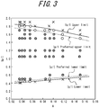
- As illustrated in
FIG. 3 , by controlling Ip/I to satisfy any of the foregoing Formulas (1) to (3) depending on the constant A, sufficient cross tension strength can be ensured even in the case where a steel sheet containing a large amount of Mn is used as a part to be welded. - The constant A is derived from any of the foregoing Formulas (4) to (6) depending on the Mn content of a steel sheet having the highest Mn content (hereafter also simply referred to as "steel sheet") of the steel sheets constituting the parts to be welded, as described above. The reason why the method of deriving the constant A needs to be changed depending on the Mn content of the steel sheet is presumed as follows.
- The constant A is defined by the Mn content and the P content of the steel sheet as indicated in the foregoing Formulas (4) to (6), and technically expresses the influence of each of the Mn content and the P content on the decrease of the toughness of the nugget. Since the influence of P tends to be promoted by an increase in the Mn content as mentioned earlier, the constant A needs to be set so that the influence of Mn relatively increases in association with an increase in the Mn content. Hence, the method of deriving the constant A needs to be changed depending on the Mn content of the steel sheet.
- The reason why the constant A is set based on the steel sheet having the highest Mn content of the steel sheets constituting the parts to be welded is that the composition of the nugget is influenced by the steel sheet having the highest Mn content.
- When A ≤ 0.04, the influence of P on the decrease of the toughness of the nugget is limited, and the decrease of the toughness of the nugget can be suppressed even if the current value of the subsequent current passage, in other words, Ip/I which is the ratio of the current value of the subsequent current passage to the current value of the main current passage, is not increased significantly in relation to the constant A. If the current value of the subsequent current passage is excessively large, expulsion (splash) occurs. In view of this, when A ≤ 0.04, the foregoing Formula (1) is to be satisfied.
- The lower limit of the foregoing Formula (1) is preferably (0.45 + A) × (1 + T)/(1 + Tp), and more preferably (0.49 + A) × (1 + T)/(1 + Tp). The upper limit of the foregoing Formula (1) is preferably (1.94 - A) × (1 + T)/(1 + Tp), and more preferably (1.84 - A) × (1 + T)/(1 + Tp).
- When 0.04 < A ≤ 0.09, the influence of segregation of P on the decrease of the toughness of the nugget is great, and the decrease of the toughness of the nugget caused by segregation of P cannot be suppressed unless the current value of the subsequent current passage, in other words, Ip/I which is the ratio of the current value of the subsequent current passage to the current value of the main current passage, is increased to a certain extent in relation to the constant A. Meanwhile, when 0.04 < A ≤ 0.09, the Mn content increases, so that the melting point of the nugget decreases with segregation of P. If the nugget remelts as a result of the subsequent current passage, the toughness improving effect by the subsequent current passage cannot be achieved. Therefore, the current value of the subsequent current passage needs to be limited to a predetermined value or less. In view of this, when 0.04 < A ≤ 0.09, the foregoing Formula (2) is to be satisfied.
- The lower limit of the foregoing Formula (2) is preferably (0.442 + 1.2 × A) × (1 + T)/(1 + Tp), and more preferably (0.482 + 1.2 × A) × (1 + T)/(1 + Tp). The upper limit of the foregoing Formula (2) is preferably (1.98 - 2 × A) × (1 + T)/(1 + Tp), and more preferably (1.88 - 2 × A) × (1 + T)/(1 + Tp).
- When 0.09 < A ≤ 0.155, the influence of segregation of P on the decrease of the toughness of the nugget is greater, and the current value of the subsequent current passage, in other words, Ip/I which is the ratio of the current value of the subsequent current passage to the current value of the main current passage, needs to be further increased in relation to the constant A. Meanwhile, in terms of achieving the toughness improving effect by the subsequent current passage, the current value of the subsequent current passage needs to be further reduced. In view of this, when 0.09 < A ≤ 0.155, the foregoing Formula (3) is to be satisfied.
- The lower limit of the foregoing Formula (3) is preferably (0.433 + 1.3 × A) × (1 + T)/(1 + Tp), and more preferably (0.473 + 1.3 × A) × (1 + T)/(1 + Tp). The upper limit of the foregoing Formula (3) is preferably (2.07 - 3 × A) × (1 + T)/(1 + Tp), and more preferably (1.97 - 3 × A) × (1 + T)/(1 + Tp).
- In terms of suppressing segregation of P, a cooling time of 0.01 s (seconds) or more (preferably 0.04 s to 0.5 s) needs to be provided between the main current passage and the subsequent current passage. If the cooling time is long, however, the nugget temperature at the start of the subsequent current passage decreases. Hence, the welding conditions of the subsequent current passage need to be adjusted depending on the cooling time, and the relationship of T and Tp needs to be incorporated in the foregoing Formulas (1) to (3).
- The technical significance of satisfying any of the foregoing Formulas (1) to (3) depending on the constant A defined by any of the foregoing Formulas (4) to (6) in the resistance spot welding method according to one of the disclosed embodiments has been described above. The welding conditions other than the above are not limited, and may be set according to conventional methods.
- For example, the welding time of the main current passage and the welding time of the subsequent current passage are preferably 0.2 s to 1.5 s and 0.04 s to 1.0 s, respectively.
- Moreover, both the main current passage and the subsequent current passage are preferably performed by constant current control, and the current value is preferably selected in a range of 4.0 kA to 15.0 kA. The electrode force is preferably 2.0 kN to 7.0 kN. The main current passage and the subsequent current passage may use the same electrode force or different electrode forces.
- In the case where welding is difficult as, for example, expulsion occurs in the main current passage, preliminary current passage may be performed before the main current passage, or upslope current passage in which current is gradually increased may be performed. The main current passage may be performed in two or more steps with a welding interval for cooling being provided therebetween, or the main current passage may be made up of multiple steps that vary in the current value during the current passage. In these cases, the current value of the subsequent current passage is determined using, as the current value of the main current passage, the current value of current passage that plays a prominent role in nugget formation.
- To achieve the effect by the subsequent current passage more favorably, the combination of the welding interval and the subsequent current passage after the main current passage may be repeatedly performed a plurality of times. If the number of repetitions is excessively large, however, the welding time increases and the construction workability decreases. Accordingly, the number of repetitions is desirably 9 or less.
- Any welding device that includes a pair of upper and lower electrodes and is capable of freely controlling each of the electrode force and the welding current during welding may be used in the resistance spot welding method according to one of the disclosed embodiments. The force mechanism (air cylinder, servomotor, etc.), the type (stationary, robot gun, etc.), the electrode shape, and the like are not limited.
- Regarding the steel sheets as the parts to be welded, as long as the chemical composition of the steel sheet having the highest Mn content satisfies 0.050 % ≤ C ≤ 0.250 %, 3.50 % ≤ Mn ≤ 12.00 %, 0.001 % ≤ Si ≤ 2.000 %, 0.001 % ≤ P ≤ 0.025 %, and 0.0001 % ≤ S ≤ 0.0020 %, the resistance spot welding method according to one of the disclosed embodiments can be used effectively. The Mn content is preferably 4.50 % or more, more preferably 4.80 % or more, and further preferably 5.00 % or more. The welding method according to one of the disclosed embodiments is more effective in such cases.
- The chemical composition may contain, besides the foregoing components, one or more selected from the group consisting of Ti: 0.001 % to 0.200 %, Al: 0.001 % to 0.200 %, B: 0.0001 % to 0.0020 %, and N: 0.0010 % to 0.0100 %.
- The balance other than these components consists of Fe and inevitable impurities.
- As along as the chemical composition of the steel sheet having the highest Mn content satisfies the foregoing range, the chemical composition of each steel sheet as the other part(s) to be welded is not limited, and steel sheets having various strengths from mild steel to ultra high tensile strength steel may be used. A plurality of steel sheets having the same chemical composition may be used as steel sheets included in the sheet combination.
- The thickness of each steel sheet is not limited, and is preferably 0.8 mm to 2.3 mm. The thickness of the sheet combination is not limited, and is preferably 1.6 mm to 6.0 mm.
- The resistance spot welding method according to one of the disclosed embodiments may also be used for a sheet combination of three or more overlapping steel sheets.
- For each sheet combination of two or three overlapping steel sheets listed in Table 2 using steel sheets having chemical compositions listed in Table 1, resistance spot welding was performed under the conditions listed in Table 2 to produce a weld joint.
- The balance other than the components in Table 1 consists of Fe and inevitable impurities.
- An inverter DC resistance spot welder was used as the welder, and chromium copper electrodes with 6 mm face diameter DR-shaped tips were used as the electrodes.
- Each of the obtained weld joints was subjected to a cross tensile test in accordance with JIS Z 3137 (1999), and evaluated based on the following criteria:
- Excellent: the fracture form is plug failure, and the plug diameter is 110 % or more of the formed nugget diameter.
- Good: the fracture form is plug failure, and the plug diameter is 100 % or more and less than 110 % of the formed nugget diameter.
- Poor: other than those rated as excellent or good (the fracture form is partial plug failure or interface failure).
- The evaluation results are listed in Table 2.
Table 1 Steel sheet No. Thickness (mm) C content (mass%) Mn content (mass%) Si content (mass%) P content (mass%) S content (mass%) Al content (mass%) N content (mass%) Ti content (mass%) B content (mass%) Value A Calculation formula for value A 1 1.2 0.146 3.53 0.247 0.020 0.0020 0.036 0.0026 - - 0.0451 A=(Mn+1.5)/200+P 2 1.2 0.149 4.56 1.956 0.010 0.0013 0.025 0.0025 - - 0.0406 A=(Mn-1.5)1100+P 3 2.0 0.153 5.09 0.209 0.001 0.0020 0.022 0.0034 - 0.0004 0.0369 A=(Mn-1.5)/100+P 4 1.6 0.145 5.09 0.224 0.011 0.0007 0.025 0.0035 0.045 - 0.0469 A=(Mn-1.5)/100+P 5 1.0 0.156 5.09 0.224 0.024 0.0004 0.034 0.0029 - - 0.0599 A=(Mn-1.5)/100+P 6 1.2 0.052 5.06 0.840 0.011 0.0020 0.036 0.0031 - - 0.0466 A=(Mn-1.5)/100+P 7 1.2 0.247 5.02 1.413 0.002 0.0001 0.038 0.0030 - - 0.0372 A=(Mn-1.5)/100+P 8 1.2 0.153 6.07 0.001 0.009 0.0015 0.021 0.0024 - - 0.0547 A=(Mn-1.5)/100+P 9 1.2 0.154 11.91 0.205 0.001 0.0001 0.020 0.0026 - - 0.1345 A=(Mn-3.9)/60+P 10 1.2 0.160 5.07 0.242 0.028 0.0015 0.031 0.0035 - - 0.0637 A=(Mn-1.5)/100+P 11 1.2 0.270 5.08 0.211 0.011 0.0007 0.033 0.0030 - - 0.0468 A=(Mn-1.5)/100+P 12 1.2 0.249 8.57 0.235 0.024 0.0016 0.030 0.0035 - - 0.1018 A=(Mn-3.9)/60+P 13 1.2 0.200 9.87 0.241 0.022 0.0018 0.025 0.0028 - - 0.1215 A=(Mn-3.9)/60+P Table 2 No. Sheet combination Constant A Electrode force (kN) Main current passage Cooling time T (s) Subsequent current passage Ip/I Minimum Ip/I Maximum Ip/I Appropriate control range of Ip/I Conformance of formula at left Evaluation result of cross tensile test Remarks Steel sheet 1 (Steel sheet No.) Steel sheet 2 (Steel sheet No.) Steel sheet 3 (Steel sheet No.) Maximum Mn content (mass%) Current value I (kA) Welding time (s) Current value Ip (kA) Welding time Tp (s) 1 1 1 - 3.53 0.0451 3.5 7.0 0.28 0.20 8.0 0.20 1.14 0.46 1.99 Formula (2) Good Excellent Example 2 1 1 - 3.53 0.0451 3.5 7.0 0.28 0.20 10.0 0.10 1.43 0.50 2.17 Formula (2) Good Excellent Example 3 1 1 - 3.53 0.0451 3.5 7.0 0.28 0.20 14.5 0.20 2.07 0.46 1.99 Formula (2) Poor Poor Comparative Example 4 1 1 - 3.53 0.0451 3.5 7.0 0.28 0.20 2.5 0.20 0.36 0.46 1.99 Formula (2) Poor Poor Comparative Example 5 2 2 - 4.56 0.0406 4.0 7.0 0.28 0.04 7.2 0.40 1.03 0.33 1.48 Formula (2) Good Excellent Example 6 2 2 - 4.56 0.0406 4.0 7.0 0.28 0.20 8.0 0.20 1.14 0.45 2.00 Formula (2) Good Excellent Example 7 2 2 - 4.56 0.0406 4.0 7.0 0.28 0.20 14.0 0.06 2.00 0.51 2.26 Formula (2) Good Excellent Example 8 2 2 - 4.56 0.0406 4.0 7.0 0.28 0.50 8.0 0.50 1.14 0.45 2.00 Formula (2) Good Excellent Example 9 2 2 - 4.56 0.0406 4.0 7.0 0.28 0.10 6.5 0.40 0.93 0.35 1.57 Formula (2) Good Good Example 10 2 2 - 4.56 0.0406 4.0 7.0 0.28 0.10 16.0 0.02 229 0.49 2.16 Formula (2) Poor Poor Comparative Example 11 2 2 - 4.56 0.0406 4.0 7.0 0.28 0.10 1.0 1.50 0.14 0.20 0.88 Formula (2) Poor Poor Comparative Example 12 2 2 - 4.56 0.0406 4.0 7.0 0.28 2.00 7.2 0.20 1.03 1.13 5.00 Formula (2) Poor Poor Comparative Example 13 3 3 - 5.09 0.0369 6.5 6.8 0.28 0.20 8.0 0.20 1.18 0.45 2.00 Formula (1) Good Excellent Example 14 3 3 - 5.09 0.0369 6.5 6.8 0.28 0.20 10.0 0.10 1.47 0.49 2.19 Formula (1) Good Excellent Example 15 3 3 - 5.09 0.0369 6.5 6.8 0.28 0.20 14.0 0.20 2.06 0.45 2.00 Formula (1) Poor Poor Comparative Example 16 3 3 - 5.09 0.0369 6.5 6.8 0.28 0.20 2.5 0.20 0.37 0.45 2.00 Formula (1) Poor Poor Comparative Example 17 4 4 - 5.09 0.0469 4.5 7.2 0.32 0.04 7.5 0.40 1.04 0.34 1.48 Formula (2) Good Excellent Example 18 4 4 - 5.09 0.0469 4.5 7.2 0.32 0.20 8.2 0.20 1.14 0.46 1.99 Formula (2) Good Excellent Example 19 4 4 - 5.09 0.0469 4.5 7.2 0.32 0.20 14.0 0.06 1.94 0.52 2.25 Formula (2) Good Excellent Example 20 4 4 - 5.09 0.0469 4.5 7.2 0.32 0.50 8.0 0.50 1.11 0.46 1.99 Formula (2) Good Excellent Example 21 4 4 - 5.09 0.0469 4.5 7.2 0.32 0.10 6.5 0.40 0.90 0.36 1.56 Formula (2) Good Good Example 22 4 4 - 5.09 0.0469 4.5 7.2 0.32 0.02 7.3 0.10 1.01 0.42 1.84 Formula (2) Good Good Example 23 4 4 - 5.09 0.0469 4.5 7.2 0.32 0.20 14.0 0.20 1.94 0.46 1.99 Formula (2) Good Good Example 24 4 4 - 5.09 0.0469 4.5 7.2 0.32 0.10 16.0 0.02 2.22 0.49 2.14 Formula (2) Poor Poor Comparative Example 25 4 4 - 5.09 0.0469 4.5 7.2 0.32 0.10 1.0 1.50 0.14 0.20 0.87 Formula (2) Poor Poor Comparative Example 26 4 4 - 5.09 0.0469 4.5 7.2 0.32 2.00 8.0 0.20 1.11 1.15 4.97 Formula (2) Poor Poor Comparative Example 27 5 5 - 5.09 0.0599 3.0 6.8 0.28 0.20 8.0 0.20 1.18 0.47 1.96 Formula (2) Good Excellent Example 28 5 5 - 5.09 0.0599 3.0 6.8 0.28 0.20 10.0 0.10 1.47 0.52 2.14 Formula (2) Good Excellent Example 29 5 5 - 5.09 0.0599 3.0 6.8 0.28 0.20 14.0 0.20 2.06 0.47 1.96 Formula (2) Poor Poor Comparative Example 30 5 5 - 5.09 0.0599 3.0 6.8 0.28 0.20 2.5 0.20 0.37 0.47 1.96 Formula (2) Poor Poor Comparative Example 31 6 6 - 5.06 0.0466 4.5 6.5 0.30 0.10 7.5 0.20 1.15 0.42 1.82 Formula (2) Good Excellent Example 32 6 6 - 5.06 0.0466 4.5 6.5 0.30 0.10 9.0 0.10 1.38 0.46 1.99 Formula (2) Good Excellent Example 33 6 6 - 5.06 0.0466 4.5 6.5 0.30 0.10 12.5 0.20 1.92 0.42 1.82 Formula (2) Poor Poor Comparative Example 34 6 6 - 5.06 0.0466 4.5 6.5 0.30 0.10 2.5 0.20 0.38 0.42 1.82 Formula (2) Poor Poor Comparative Example 35 7 7 - 5.02 0.0372 4.5 6.5 0.30 0.10 7.5 0.20 1.15 0.41 1.84 Formula (1) Good Excellent Example 36 7 7 - 5.02 0.0372 4.5 6.5 0.30 0.10 9.0 0.10 1.38 0.45 2.00 Formula (1) Good Excellent Example 37 7 7 - 5.02 0.0372 4.5 6.5 0.30 0.10 12.5 0.20 1.92 0.41 1.84 Formula (1) Poor Poor Comparative Example 38 7 7 - 5.02 0.0372 4.5 6.5 0.30 0.10 2.5 0.20 0.38 0.41 1.84 Formula (1) Poor Poor Comparative Example 39 8 8 - 6.07 0.0547 4.5 7.5 0.32 0.04 8.0 0.20 1.07 0.41 1.71 Formula (2) Good Excellent Example 40 8 8 - 6.07 0.0547 4.5 7.5 0.32 0.20 9.0 0.10 1.20 0.51 2.15 Formula (2) Good Excellent Example 41 8 8 - 6.07 0.0547 4.5 7.5 0.32 0.20 15.0 0.06 2.00 0.53 2.23 Formula (2) Good Excellent Example 42 8 8 - 6.07 0.0547 4.5 7.5 0.32 0.50 8.0 0.50 1.07 0.47 1.97 Formula (2) Good Excellent Example 43 8 8 - 6.07 0.0547 4.5 7.5 0.32 0.10 6.5 0.40 0.87 0.37 1.55 Formula (2) Good Good Example 44 8 8 - 6.07 0.0547 4.5 7.5 0.32 0.02 7.3 0.10 0.97 0.43 1.83 Formula (2) Good Good Example 45 8 8 - 6.07 0.0547 4.5 7.5 0.32 0.10 17.0 0.02 2.27 0.50 2.13 Formula (2) Poor Poor Comparative Example 46 8 8 - 6.07 0.0547 4.5 7.5 0.32 0.10 1.0 1.50 0.13 0.21 0.87 Formula (2) Poor Poor Comparative Example 47 8 8 - 6.07 0.0547 4.5 7.5 0.32 2.00 8.0 0.20 1.07 1.17 4.93 Formula (2) Poor Poor Comparative Example 48 9 9 - 11.91 0.1345 4.5 7.0 0.30 0.10 7.5 0.20 1.07 0.52 1.62 Formula (3) Good Excellent Example 49 9 9 - 11.91 0.1345 4.5 7.0 0.30 0.10 9.0 0.10 1.29 0.57 1.77 Formula (3) Good Excellent Example 50 9 9 - 11.91 0.1345 4.5 7.0 0.30 0.10 12.5 0.20 1.79 0.52 1.62 Formula (3) Poor Poor Comparative Example 51 9 9 - 11.91 0.1345 4.5 7.0 0.30 0.10 3.5 0.20 0.50 0.52 1.62 Formula (3) Poor Poor Comparative Example 52 10 10 - 5.07 0.0637 6.5 6.8 0.28 0.20 8.0 0.20 1.18 0.48 1.95 Formula (2) Good Poor Comparative Example 53 11 11 - 5.08 0.0468 6.5 6.8 0.28 0.20 8.0 0.20 1.18 0.46 1.99 Formula (2) Good Poor Comparative Example 54 5 5 5 5.09 0.0599 6.5 6.8 0.28 0.20 8.0 0.20 1.18 0.47 1.96 Formula (2) Good Excellent Example 55 5 5 5 5.09 0.0599 6.5 6.8 0.28 0.20 10.0 0.10 1.47 0.52 2.14 Formula (2) Good Excellent Example 56 5 5 5 5.09 0.0599 6.5 6.8 0.28 0.20 14.0 0.20 2.06 0.47 1.96 Formula (2) Poor Poor Comparative Example 57 5 5 5 5.09 0.0599 6.5 6.8 0.28 0.20 2.5 0.20 0.37 0.47 1.96 Formula (2) Poor Poor Comparative Example 58 2 2 - 4.56 0.0406 4.0 7.0 0.28 0.10 7.1 1.20 1.01 0.23 1.00 Formula (2) Poor Poor Comparative Example 59 2 2 - 4.56 0.0406 4.0 7.0 0.28 0.20 5.0 0.20 0.71 0.45 2.00 Formula (2) Good Good Example 60 2 2 - 4.56 0.0406 4.0 7.0 0.28 0.20 8.5 0.40 1.21 0.39 1.71 Formula (2) Good Good Example 61 12 12 - 8.57 0.1018 4.0 7.1 0.28 1.00 7.5 0.20 1.06 0.88 3.11 Formula (3) Good Good Example 62 12 12 - 8.57 0.1018 4.0 6.5 0.28 1.00 14.2 1.30 2.18 0.46 1.62 Formula (3) Poor Poor Comparative Example 63 13 13 - 9.87 0.1215 4.0 7.2 0.28 1.00 7.6 0.20 1.06 0.92 3.01 Formula (3) Good Good Example 64 13 13 - 9.87 0.1215 4.0 7.7 0.28 0.30 7.7 2.00 1.00 0.24 0.78 Formula (3) Poor Poor Comparative Example 65 1 13 - 9.87 0.1215 4.5 7.5 0.28 0.50 3.2 1.00 0.43 0.41 1.35 Formula (3) Good Good Example 66 1 7 - 5.02 0.0372 4.5 7.0 0.28 0.80 3.0 0.90 0.43 0.42 1.90 Formula (1) Good Good Example - In all Examples, the fracture form was plug failure. In all Examples, the nugget diameter was sufficient, and no expulsion occurred. In all Comparative Examples, on the other hand, the fracture form was partial plug failure or plug failure (interface failure), and favorable fracture form was not obtained.
-
- 1, 2
- steel sheet
- 3
- sheet combination (parts to be welded)
- 4, 5
- electrode
- 6
- nugget
Claims (1)
- A resistance spot welding method of joining parts to be welded that are two or more overlapping steel sheets,
wherein a steel sheet whose Mn content is highest of the overlapping steel sheets has a chemical composition that satisfies
0.050 % ≤ C ≤ 0.250 %,
3.50 % ≤ Mn ≤ 12.00 %,
0.001 % ≤ Si ≤ 2.000 %,
0.001 % ≤ P ≤ 0.025 %, and
0.0001 % ≤ S ≤ 0.0020 %,
the resistance spot welding method comprises
performing main current passage and subsequent current passage, with a cooling time of 0.01 s or more being provided between the main current passage and the subsequent current passage, and
Ip/I which is a ratio of a current value of the subsequent current passage to a current value of the main current passage satisfies, depending on a constant A defined by the Mn content and P content in the chemical composition, any of the following Formulas (1) to (3) in relation to Tp, T, and the constant A:when A ≤ 0.04, when 0.04 ≤ A ≤ 0.09,
andwhen 0.09 ≤ A ≤ 0.155,where I denotes the current value of the main current passage expressed in kA, Ip denotes the current value of the subsequent current passage expressed in kA, Tp denotes a welding time of the subsequent current passage expressed in s, T denotes the cooling time expressed in s, and the constant A is defined by any of the following Formulas (4) to (6) depending on the Mn content: when 3.5 % ≤ Mn ≤ 4.5 %,
 when 4.5 % < Mn ≤ 7.5 %,
 when 7.5 % < Mn ≤ 12.0 %,where Mn and P are respectively the Mn content and the P content in the chemical composition.
Applications Claiming Priority (2)
| Application Number | Priority Date | Filing Date | Title |
|---|---|---|---|
| JP2017175983 | 2017-09-13 | ||
| PCT/JP2018/030309 WO2019054116A1 (en) | 2017-09-13 | 2018-08-14 | Resistance spot welding method |
Publications (3)
| Publication Number | Publication Date |
|---|---|
| EP3682997A1 true EP3682997A1 (en) | 2020-07-22 |
| EP3682997A4 EP3682997A4 (en) | 2021-03-31 |
| EP3682997B1 EP3682997B1 (en) | 2022-03-09 |
Family
ID=65722674
Family Applications (1)
| Application Number | Title | Priority Date | Filing Date |
|---|---|---|---|
| EP18856855.4A Active EP3682997B1 (en) | 2017-09-13 | 2018-08-14 | Resistance spot welding method |
Country Status (7)
| Country | Link |
|---|---|
| US (1) | US11498150B2 (en) |
| EP (1) | EP3682997B1 (en) |
| JP (1) | JP6493641B1 (en) |
| KR (1) | KR102253193B1 (en) |
| CN (1) | CN111065483B (en) |
| MX (1) | MX2020002784A (en) |
| WO (1) | WO2019054116A1 (en) |
Family Cites Families (9)
| Publication number | Priority date | Publication date | Assignee | Title |
|---|---|---|---|---|
| JPS6011596B2 (en) | 1981-06-29 | 1985-03-27 | 川崎製鉄株式会社 | Spot welding method for high-strength steel plates |
| JPS6011597B2 (en) | 1981-06-29 | 1985-03-27 | 川崎製鉄株式会社 | Spot welding method for high-strength steel plates |
| KR101388692B1 (en) | 2009-08-31 | 2014-04-24 | 신닛테츠스미킨 카부시키카이샤 | Spot-welded joint and spot welding method |
| JP5333560B2 (en) | 2011-10-18 | 2013-11-06 | Jfeスチール株式会社 | Resistance spot welding method and resistance spot welding joint of high strength steel plate |
| US10081073B2 (en) | 2012-04-25 | 2018-09-25 | Nippon Steel & Sumitomo Metal Corporation | Spot welded joint |
| JP5429327B2 (en) * | 2012-05-30 | 2014-02-26 | 新日鐵住金株式会社 | Spot welding method for high strength steel sheet |
| CN105263663B (en) * | 2013-06-05 | 2017-07-21 | 新日铁住金株式会社 | Tack-weld and spot welding method |
| JP6409470B2 (en) * | 2014-09-30 | 2018-10-24 | 新日鐵住金株式会社 | Spot welding method |
| CN107427953B (en) | 2015-03-05 | 2019-10-08 | 杰富意钢铁株式会社 | Resistance spot welding method and welding point |
-
2018
- 2018-08-14 CN CN201880059005.8A patent/CN111065483B/en active Active
- 2018-08-14 WO PCT/JP2018/030309 patent/WO2019054116A1/en unknown
- 2018-08-14 KR KR1020207006916A patent/KR102253193B1/en active IP Right Grant
- 2018-08-14 US US16/645,789 patent/US11498150B2/en active Active
- 2018-08-14 EP EP18856855.4A patent/EP3682997B1/en active Active
- 2018-08-14 MX MX2020002784A patent/MX2020002784A/en unknown
- 2018-08-14 JP JP2018560921A patent/JP6493641B1/en active Active
Also Published As
| Publication number | Publication date |
|---|---|
| CN111065483B (en) | 2021-09-28 |
| JPWO2019054116A1 (en) | 2019-11-07 |
| EP3682997B1 (en) | 2022-03-09 |
| EP3682997A4 (en) | 2021-03-31 |
| US11498150B2 (en) | 2022-11-15 |
| MX2020002784A (en) | 2020-07-22 |
| US20200269342A1 (en) | 2020-08-27 |
| WO2019054116A1 (en) | 2019-03-21 |
| KR20200039744A (en) | 2020-04-16 |
| KR102253193B1 (en) | 2021-05-17 |
| CN111065483A (en) | 2020-04-24 |
| JP6493641B1 (en) | 2019-04-03 |
Similar Documents
| Publication | Publication Date | Title |
|---|---|---|
| US10099311B2 (en) | Spot welding method | |
| JP6958765B1 (en) | Resistance spot welding method and resistance spot welding joint manufacturing method | |
| EP3028799A1 (en) | Arc spot weld joint and method for producing same | |
| KR101592808B1 (en) | Spot-welding joint | |
| JP2008229720A (en) | Spot-welded joint of high-strength steel sheets excellent in tensile strength, automotive component having the same joint, and spot-welding method of high-strength steel sheets | |
| EP3736076B1 (en) | Resistance spot welding method, and method for producing resistance-spot-welded joint | |
| WO2018159719A1 (en) | Fillet welded joint and manufacturing method thereof | |
| JP6879345B2 (en) | Resistance spot welding method, resistance spot welding joint manufacturing method | |
| CN105189013A (en) | Spot welded joint | |
| EP3459671A1 (en) | Joining structure and method for manufacturing joining structure | |
| EP3682997B1 (en) | Resistance spot welding method | |
| EP3495524A1 (en) | Arc spot welding method | |
| WO2020036198A1 (en) | Resistance spot-welded member and manufacturing method therefor | |
| EP4043140A1 (en) | Resistance spot welding method and method for manufacturing welded member | |
| EP3995246B1 (en) | Method of manufacturing resistance spot welded joint | |
| EP4494798A1 (en) | Method for predicting resistance spot welding spatter generation, resistance spot welding method, and method for manufacturing welded member | |
| JP7332065B1 (en) | Resistance spot welding joint and resistance spot welding method thereof | |
| JP7560006B1 (en) | Projection welded joint and its manufacturing method | |
| EP4043141A1 (en) | Resistance spot welding method and method for manufacturing welded member | |
| EP4484044A1 (en) | Welded joint, welding member, method for manufacturing same, and method of resistance spot welding | |
| WO2024225344A1 (en) | Projection welded joint and method for manufacturing same | |
| WO2024225340A1 (en) | Projection weld joint and method for manufacturing same | |
| WO2024225343A1 (en) | Projection welded joint and manufacturing method therefor |
Legal Events
| Date | Code | Title | Description |
|---|---|---|---|
| STAA | Information on the status of an ep patent application or granted ep patent |
Free format text: STATUS: THE INTERNATIONAL PUBLICATION HAS BEEN MADE |
|
| PUAI | Public reference made under article 153(3) epc to a published international application that has entered the european phase |
Free format text: ORIGINAL CODE: 0009012 |
|
| STAA | Information on the status of an ep patent application or granted ep patent |
Free format text: STATUS: REQUEST FOR EXAMINATION WAS MADE |
|
| 17P | Request for examination filed |
Effective date: 20200311 |
|
| AK | Designated contracting states |
Kind code of ref document: A1 Designated state(s): AL AT BE BG CH CY CZ DE DK EE ES FI FR GB GR HR HU IE IS IT LI LT LU LV MC MK MT NL NO PL PT RO RS SE SI SK SM TR |
|
| AX | Request for extension of the european patent |
Extension state: BA ME |
|
| DAV | Request for validation of the european patent (deleted) | ||
| DAX | Request for extension of the european patent (deleted) | ||
| A4 | Supplementary search report drawn up and despatched |
Effective date: 20210301 |
|
| RIC1 | Information provided on ipc code assigned before grant |
Ipc: C22C 38/04 20060101ALI20210223BHEP Ipc: C22C 38/00 20060101ALI20210223BHEP Ipc: B23K 11/11 20060101AFI20210223BHEP Ipc: B23K 11/16 20060101ALI20210223BHEP Ipc: C22C 38/14 20060101ALI20210223BHEP |
|
| GRAP | Despatch of communication of intention to grant a patent |
Free format text: ORIGINAL CODE: EPIDOSNIGR1 |
|
| STAA | Information on the status of an ep patent application or granted ep patent |
Free format text: STATUS: GRANT OF PATENT IS INTENDED |
|
| INTG | Intention to grant announced |
Effective date: 20211005 |
|
| RAP3 | Party data changed (applicant data changed or rights of an application transferred) |
Owner name: JFE STEEL CORPORATION |
|
| GRAS | Grant fee paid |
Free format text: ORIGINAL CODE: EPIDOSNIGR3 |
|
| GRAA | (expected) grant |
Free format text: ORIGINAL CODE: 0009210 |
|
| STAA | Information on the status of an ep patent application or granted ep patent |
Free format text: STATUS: THE PATENT HAS BEEN GRANTED |
|
| AK | Designated contracting states |
Kind code of ref document: B1 Designated state(s): AL AT BE BG CH CY CZ DE DK EE ES FI FR GB GR HR HU IE IS IT LI LT LU LV MC MK MT NL NO PL PT RO RS SE SI SK SM TR |
|
| REG | Reference to a national code |
Ref country code: CH Ref legal event code: EP Ref country code: AT Ref legal event code: REF Ref document number: 1473705 Country of ref document: AT Kind code of ref document: T Effective date: 20220315 |
|
| REG | Reference to a national code |
Ref country code: DE Ref legal event code: R096 Ref document number: 602018032137 Country of ref document: DE |
|
| REG | Reference to a national code |
Ref country code: IE Ref legal event code: FG4D |
|
| REG | Reference to a national code |
Ref country code: LT Ref legal event code: MG9D |
|
| REG | Reference to a national code |
Ref country code: NL Ref legal event code: MP Effective date: 20220309 |
|
| PG25 | Lapsed in a contracting state [announced via postgrant information from national office to epo] |
Ref country code: SE Free format text: LAPSE BECAUSE OF FAILURE TO SUBMIT A TRANSLATION OF THE DESCRIPTION OR TO PAY THE FEE WITHIN THE PRESCRIBED TIME-LIMIT Effective date: 20220309 Ref country code: RS Free format text: LAPSE BECAUSE OF FAILURE TO SUBMIT A TRANSLATION OF THE DESCRIPTION OR TO PAY THE FEE WITHIN THE PRESCRIBED TIME-LIMIT Effective date: 20220309 Ref country code: NO Free format text: LAPSE BECAUSE OF FAILURE TO SUBMIT A TRANSLATION OF THE DESCRIPTION OR TO PAY THE FEE WITHIN THE PRESCRIBED TIME-LIMIT Effective date: 20220609 Ref country code: LT Free format text: LAPSE BECAUSE OF FAILURE TO SUBMIT A TRANSLATION OF THE DESCRIPTION OR TO PAY THE FEE WITHIN THE PRESCRIBED TIME-LIMIT Effective date: 20220309 Ref country code: HR Free format text: LAPSE BECAUSE OF FAILURE TO SUBMIT A TRANSLATION OF THE DESCRIPTION OR TO PAY THE FEE WITHIN THE PRESCRIBED TIME-LIMIT Effective date: 20220309 Ref country code: BG Free format text: LAPSE BECAUSE OF FAILURE TO SUBMIT A TRANSLATION OF THE DESCRIPTION OR TO PAY THE FEE WITHIN THE PRESCRIBED TIME-LIMIT Effective date: 20220609 |
|
| REG | Reference to a national code |
Ref country code: AT Ref legal event code: MK05 Ref document number: 1473705 Country of ref document: AT Kind code of ref document: T Effective date: 20220309 |
|
| PG25 | Lapsed in a contracting state [announced via postgrant information from national office to epo] |
Ref country code: LV Free format text: LAPSE BECAUSE OF FAILURE TO SUBMIT A TRANSLATION OF THE DESCRIPTION OR TO PAY THE FEE WITHIN THE PRESCRIBED TIME-LIMIT Effective date: 20220309 Ref country code: GR Free format text: LAPSE BECAUSE OF FAILURE TO SUBMIT A TRANSLATION OF THE DESCRIPTION OR TO PAY THE FEE WITHIN THE PRESCRIBED TIME-LIMIT Effective date: 20220610 Ref country code: FI Free format text: LAPSE BECAUSE OF FAILURE TO SUBMIT A TRANSLATION OF THE DESCRIPTION OR TO PAY THE FEE WITHIN THE PRESCRIBED TIME-LIMIT Effective date: 20220309 |
|
| PG25 | Lapsed in a contracting state [announced via postgrant information from national office to epo] |
Ref country code: NL Free format text: LAPSE BECAUSE OF FAILURE TO SUBMIT A TRANSLATION OF THE DESCRIPTION OR TO PAY THE FEE WITHIN THE PRESCRIBED TIME-LIMIT Effective date: 20220309 |
|
| PG25 | Lapsed in a contracting state [announced via postgrant information from national office to epo] |
Ref country code: SM Free format text: LAPSE BECAUSE OF FAILURE TO SUBMIT A TRANSLATION OF THE DESCRIPTION OR TO PAY THE FEE WITHIN THE PRESCRIBED TIME-LIMIT Effective date: 20220309 Ref country code: SK Free format text: LAPSE BECAUSE OF FAILURE TO SUBMIT A TRANSLATION OF THE DESCRIPTION OR TO PAY THE FEE WITHIN THE PRESCRIBED TIME-LIMIT Effective date: 20220309 Ref country code: RO Free format text: LAPSE BECAUSE OF FAILURE TO SUBMIT A TRANSLATION OF THE DESCRIPTION OR TO PAY THE FEE WITHIN THE PRESCRIBED TIME-LIMIT Effective date: 20220309 Ref country code: PT Free format text: LAPSE BECAUSE OF FAILURE TO SUBMIT A TRANSLATION OF THE DESCRIPTION OR TO PAY THE FEE WITHIN THE PRESCRIBED TIME-LIMIT Effective date: 20220711 Ref country code: ES Free format text: LAPSE BECAUSE OF FAILURE TO SUBMIT A TRANSLATION OF THE DESCRIPTION OR TO PAY THE FEE WITHIN THE PRESCRIBED TIME-LIMIT Effective date: 20220309 Ref country code: EE Free format text: LAPSE BECAUSE OF FAILURE TO SUBMIT A TRANSLATION OF THE DESCRIPTION OR TO PAY THE FEE WITHIN THE PRESCRIBED TIME-LIMIT Effective date: 20220309 Ref country code: CZ Free format text: LAPSE BECAUSE OF FAILURE TO SUBMIT A TRANSLATION OF THE DESCRIPTION OR TO PAY THE FEE WITHIN THE PRESCRIBED TIME-LIMIT Effective date: 20220309 Ref country code: AT Free format text: LAPSE BECAUSE OF FAILURE TO SUBMIT A TRANSLATION OF THE DESCRIPTION OR TO PAY THE FEE WITHIN THE PRESCRIBED TIME-LIMIT Effective date: 20220309 |
|
| PG25 | Lapsed in a contracting state [announced via postgrant information from national office to epo] |
Ref country code: PL Free format text: LAPSE BECAUSE OF FAILURE TO SUBMIT A TRANSLATION OF THE DESCRIPTION OR TO PAY THE FEE WITHIN THE PRESCRIBED TIME-LIMIT Effective date: 20220309 Ref country code: IS Free format text: LAPSE BECAUSE OF FAILURE TO SUBMIT A TRANSLATION OF THE DESCRIPTION OR TO PAY THE FEE WITHIN THE PRESCRIBED TIME-LIMIT Effective date: 20220709 Ref country code: AL Free format text: LAPSE BECAUSE OF FAILURE TO SUBMIT A TRANSLATION OF THE DESCRIPTION OR TO PAY THE FEE WITHIN THE PRESCRIBED TIME-LIMIT Effective date: 20220309 |
|
| REG | Reference to a national code |
Ref country code: DE Ref legal event code: R097 Ref document number: 602018032137 Country of ref document: DE |
|
| PLBE | No opposition filed within time limit |
Free format text: ORIGINAL CODE: 0009261 |
|
| STAA | Information on the status of an ep patent application or granted ep patent |
Free format text: STATUS: NO OPPOSITION FILED WITHIN TIME LIMIT |
|
| PG25 | Lapsed in a contracting state [announced via postgrant information from national office to epo] |
Ref country code: DK Free format text: LAPSE BECAUSE OF FAILURE TO SUBMIT A TRANSLATION OF THE DESCRIPTION OR TO PAY THE FEE WITHIN THE PRESCRIBED TIME-LIMIT Effective date: 20220309 |
|
| 26N | No opposition filed |
Effective date: 20221212 |
|
| PG25 | Lapsed in a contracting state [announced via postgrant information from national office to epo] |
Ref country code: SI Free format text: LAPSE BECAUSE OF FAILURE TO SUBMIT A TRANSLATION OF THE DESCRIPTION OR TO PAY THE FEE WITHIN THE PRESCRIBED TIME-LIMIT Effective date: 20220309 |
|
| PG25 | Lapsed in a contracting state [announced via postgrant information from national office to epo] |
Ref country code: MC Free format text: LAPSE BECAUSE OF FAILURE TO SUBMIT A TRANSLATION OF THE DESCRIPTION OR TO PAY THE FEE WITHIN THE PRESCRIBED TIME-LIMIT Effective date: 20220309 |
|
| REG | Reference to a national code |
Ref country code: CH Ref legal event code: PL |
|
| GBPC | Gb: european patent ceased through non-payment of renewal fee |
Effective date: 20220814 |
|
| PG25 | Lapsed in a contracting state [announced via postgrant information from national office to epo] |
Ref country code: LU Free format text: LAPSE BECAUSE OF NON-PAYMENT OF DUE FEES Effective date: 20220814 Ref country code: LI Free format text: LAPSE BECAUSE OF NON-PAYMENT OF DUE FEES Effective date: 20220831 Ref country code: CH Free format text: LAPSE BECAUSE OF NON-PAYMENT OF DUE FEES Effective date: 20220831 |
|
| REG | Reference to a national code |
Ref country code: BE Ref legal event code: MM Effective date: 20220831 |
|
| PG25 | Lapsed in a contracting state [announced via postgrant information from national office to epo] |
Ref country code: IT Free format text: LAPSE BECAUSE OF FAILURE TO SUBMIT A TRANSLATION OF THE DESCRIPTION OR TO PAY THE FEE WITHIN THE PRESCRIBED TIME-LIMIT Effective date: 20220309 Ref country code: IE Free format text: LAPSE BECAUSE OF NON-PAYMENT OF DUE FEES Effective date: 20220814 |
|
| PG25 | Lapsed in a contracting state [announced via postgrant information from national office to epo] |
Ref country code: BE Free format text: LAPSE BECAUSE OF NON-PAYMENT OF DUE FEES Effective date: 20220831 |
|
| PG25 | Lapsed in a contracting state [announced via postgrant information from national office to epo] |
Ref country code: GB Free format text: LAPSE BECAUSE OF NON-PAYMENT OF DUE FEES Effective date: 20220814 |
|
| PG25 | Lapsed in a contracting state [announced via postgrant information from national office to epo] |
Ref country code: CY Free format text: LAPSE BECAUSE OF FAILURE TO SUBMIT A TRANSLATION OF THE DESCRIPTION OR TO PAY THE FEE WITHIN THE PRESCRIBED TIME-LIMIT Effective date: 20220309 |
|
| PG25 | Lapsed in a contracting state [announced via postgrant information from national office to epo] |
Ref country code: MK Free format text: LAPSE BECAUSE OF FAILURE TO SUBMIT A TRANSLATION OF THE DESCRIPTION OR TO PAY THE FEE WITHIN THE PRESCRIBED TIME-LIMIT Effective date: 20220309 Ref country code: HU Free format text: LAPSE BECAUSE OF FAILURE TO SUBMIT A TRANSLATION OF THE DESCRIPTION OR TO PAY THE FEE WITHIN THE PRESCRIBED TIME-LIMIT; INVALID AB INITIO Effective date: 20180814 |
|
| PG25 | Lapsed in a contracting state [announced via postgrant information from national office to epo] |
Ref country code: MT Free format text: LAPSE BECAUSE OF FAILURE TO SUBMIT A TRANSLATION OF THE DESCRIPTION OR TO PAY THE FEE WITHIN THE PRESCRIBED TIME-LIMIT Effective date: 20220309 |
|
| PGFP | Annual fee paid to national office [announced via postgrant information from national office to epo] |
Ref country code: DE Payment date: 20240702 Year of fee payment: 7 |
|
| PGFP | Annual fee paid to national office [announced via postgrant information from national office to epo] |
Ref country code: FR Payment date: 20240702 Year of fee payment: 7 |
|
| PGFP | Annual fee paid to national office [announced via postgrant information from national office to epo] |
Ref country code: TR Payment date: 20240724 Year of fee payment: 7 |