EP3682988A1 - Method for producing rotor blades from ni base alloys and rotor blade produced according to said method - Google Patents
Method for producing rotor blades from ni base alloys and rotor blade produced according to said method Download PDFInfo
- Publication number
- EP3682988A1 EP3682988A1 EP20151270.4A EP20151270A EP3682988A1 EP 3682988 A1 EP3682988 A1 EP 3682988A1 EP 20151270 A EP20151270 A EP 20151270A EP 3682988 A1 EP3682988 A1 EP 3682988A1
- Authority
- EP
- European Patent Office
- Prior art keywords
- component
- area
- different
- powder
- property profile
- Prior art date
- Legal status (The legal status is an assumption and is not a legal conclusion. Google has not performed a legal analysis and makes no representation as to the accuracy of the status listed.)
- Pending
Links
Images
Classifications
-
- B—PERFORMING OPERATIONS; TRANSPORTING
- B22—CASTING; POWDER METALLURGY
- B22F—WORKING METALLIC POWDER; MANUFACTURE OF ARTICLES FROM METALLIC POWDER; MAKING METALLIC POWDER; APPARATUS OR DEVICES SPECIALLY ADAPTED FOR METALLIC POWDER
- B22F5/00—Manufacture of workpieces or articles from metallic powder characterised by the special shape of the product
- B22F5/04—Manufacture of workpieces or articles from metallic powder characterised by the special shape of the product of turbine blades
-
- B—PERFORMING OPERATIONS; TRANSPORTING
- B22—CASTING; POWDER METALLURGY
- B22F—WORKING METALLIC POWDER; MANUFACTURE OF ARTICLES FROM METALLIC POWDER; MAKING METALLIC POWDER; APPARATUS OR DEVICES SPECIALLY ADAPTED FOR METALLIC POWDER
- B22F10/00—Additive manufacturing of workpieces or articles from metallic powder
- B22F10/20—Direct sintering or melting
- B22F10/28—Powder bed fusion, e.g. selective laser melting [SLM] or electron beam melting [EBM]
-
- B—PERFORMING OPERATIONS; TRANSPORTING
- B22—CASTING; POWDER METALLURGY
- B22F—WORKING METALLIC POWDER; MANUFACTURE OF ARTICLES FROM METALLIC POWDER; MAKING METALLIC POWDER; APPARATUS OR DEVICES SPECIALLY ADAPTED FOR METALLIC POWDER
- B22F10/00—Additive manufacturing of workpieces or articles from metallic powder
- B22F10/30—Process control
- B22F10/32—Process control of the atmosphere, e.g. composition or pressure in a building chamber
-
- B—PERFORMING OPERATIONS; TRANSPORTING
- B22—CASTING; POWDER METALLURGY
- B22F—WORKING METALLIC POWDER; MANUFACTURE OF ARTICLES FROM METALLIC POWDER; MAKING METALLIC POWDER; APPARATUS OR DEVICES SPECIALLY ADAPTED FOR METALLIC POWDER
- B22F10/00—Additive manufacturing of workpieces or articles from metallic powder
- B22F10/30—Process control
- B22F10/36—Process control of energy beam parameters
-
- B—PERFORMING OPERATIONS; TRANSPORTING
- B22—CASTING; POWDER METALLURGY
- B22F—WORKING METALLIC POWDER; MANUFACTURE OF ARTICLES FROM METALLIC POWDER; MAKING METALLIC POWDER; APPARATUS OR DEVICES SPECIALLY ADAPTED FOR METALLIC POWDER
- B22F10/00—Additive manufacturing of workpieces or articles from metallic powder
- B22F10/30—Process control
- B22F10/38—Process control to achieve specific product aspects, e.g. surface smoothness, density, porosity or hollow structures
-
- B—PERFORMING OPERATIONS; TRANSPORTING
- B22—CASTING; POWDER METALLURGY
- B22F—WORKING METALLIC POWDER; MANUFACTURE OF ARTICLES FROM METALLIC POWDER; MAKING METALLIC POWDER; APPARATUS OR DEVICES SPECIALLY ADAPTED FOR METALLIC POWDER
- B22F12/00—Apparatus or devices specially adapted for additive manufacturing; Auxiliary means for additive manufacturing; Combinations of additive manufacturing apparatus or devices with other processing apparatus or devices
- B22F12/10—Auxiliary heating means
- B22F12/13—Auxiliary heating means to preheat the material
-
- B—PERFORMING OPERATIONS; TRANSPORTING
- B22—CASTING; POWDER METALLURGY
- B22F—WORKING METALLIC POWDER; MANUFACTURE OF ARTICLES FROM METALLIC POWDER; MAKING METALLIC POWDER; APPARATUS OR DEVICES SPECIALLY ADAPTED FOR METALLIC POWDER
- B22F5/00—Manufacture of workpieces or articles from metallic powder characterised by the special shape of the product
- B22F5/009—Manufacture of workpieces or articles from metallic powder characterised by the special shape of the product of turbine components other than turbine blades
-
- B—PERFORMING OPERATIONS; TRANSPORTING
- B22—CASTING; POWDER METALLURGY
- B22F—WORKING METALLIC POWDER; MANUFACTURE OF ARTICLES FROM METALLIC POWDER; MAKING METALLIC POWDER; APPARATUS OR DEVICES SPECIALLY ADAPTED FOR METALLIC POWDER
- B22F7/00—Manufacture of composite layers, workpieces, or articles, comprising metallic powder, by sintering the powder, with or without compacting wherein at least one part is obtained by sintering or compression
- B22F7/06—Manufacture of composite layers, workpieces, or articles, comprising metallic powder, by sintering the powder, with or without compacting wherein at least one part is obtained by sintering or compression of composite workpieces or articles from parts, e.g. to form tipped tools
- B22F7/08—Manufacture of composite layers, workpieces, or articles, comprising metallic powder, by sintering the powder, with or without compacting wherein at least one part is obtained by sintering or compression of composite workpieces or articles from parts, e.g. to form tipped tools with one or more parts not made from powder
-
- B—PERFORMING OPERATIONS; TRANSPORTING
- B23—MACHINE TOOLS; METAL-WORKING NOT OTHERWISE PROVIDED FOR
- B23K—SOLDERING OR UNSOLDERING; WELDING; CLADDING OR PLATING BY SOLDERING OR WELDING; CUTTING BY APPLYING HEAT LOCALLY, e.g. FLAME CUTTING; WORKING BY LASER BEAM
- B23K15/00—Electron-beam welding or cutting
- B23K15/0046—Welding
- B23K15/0086—Welding welding for purposes other than joining, e.g. built-up welding
-
- B—PERFORMING OPERATIONS; TRANSPORTING
- B23—MACHINE TOOLS; METAL-WORKING NOT OTHERWISE PROVIDED FOR
- B23K—SOLDERING OR UNSOLDERING; WELDING; CLADDING OR PLATING BY SOLDERING OR WELDING; CUTTING BY APPLYING HEAT LOCALLY, e.g. FLAME CUTTING; WORKING BY LASER BEAM
- B23K26/00—Working by laser beam, e.g. welding, cutting or boring
- B23K26/14—Working by laser beam, e.g. welding, cutting or boring using a fluid stream, e.g. a jet of gas, in conjunction with the laser beam; Nozzles therefor
- B23K26/1462—Nozzles; Features related to nozzles
- B23K26/1464—Supply to, or discharge from, nozzles of media, e.g. gas, powder, wire
-
- B—PERFORMING OPERATIONS; TRANSPORTING
- B23—MACHINE TOOLS; METAL-WORKING NOT OTHERWISE PROVIDED FOR
- B23K—SOLDERING OR UNSOLDERING; WELDING; CLADDING OR PLATING BY SOLDERING OR WELDING; CUTTING BY APPLYING HEAT LOCALLY, e.g. FLAME CUTTING; WORKING BY LASER BEAM
- B23K26/00—Working by laser beam, e.g. welding, cutting or boring
- B23K26/20—Bonding
- B23K26/32—Bonding taking account of the properties of the material involved
- B23K26/323—Bonding taking account of the properties of the material involved involving parts made of dissimilar metallic material
-
- B—PERFORMING OPERATIONS; TRANSPORTING
- B23—MACHINE TOOLS; METAL-WORKING NOT OTHERWISE PROVIDED FOR
- B23K—SOLDERING OR UNSOLDERING; WELDING; CLADDING OR PLATING BY SOLDERING OR WELDING; CUTTING BY APPLYING HEAT LOCALLY, e.g. FLAME CUTTING; WORKING BY LASER BEAM
- B23K26/00—Working by laser beam, e.g. welding, cutting or boring
- B23K26/34—Laser welding for purposes other than joining
- B23K26/342—Build-up welding
-
- B—PERFORMING OPERATIONS; TRANSPORTING
- B23—MACHINE TOOLS; METAL-WORKING NOT OTHERWISE PROVIDED FOR
- B23K—SOLDERING OR UNSOLDERING; WELDING; CLADDING OR PLATING BY SOLDERING OR WELDING; CUTTING BY APPLYING HEAT LOCALLY, e.g. FLAME CUTTING; WORKING BY LASER BEAM
- B23K26/00—Working by laser beam, e.g. welding, cutting or boring
- B23K26/60—Preliminary treatment
-
- B—PERFORMING OPERATIONS; TRANSPORTING
- B29—WORKING OF PLASTICS; WORKING OF SUBSTANCES IN A PLASTIC STATE IN GENERAL
- B29C—SHAPING OR JOINING OF PLASTICS; SHAPING OF MATERIAL IN A PLASTIC STATE, NOT OTHERWISE PROVIDED FOR; AFTER-TREATMENT OF THE SHAPED PRODUCTS, e.g. REPAIRING
- B29C64/00—Additive manufacturing, i.e. manufacturing of three-dimensional [3D] objects by additive deposition, additive agglomeration or additive layering, e.g. by 3D printing, stereolithography or selective laser sintering
- B29C64/10—Processes of additive manufacturing
- B29C64/141—Processes of additive manufacturing using only solid materials
- B29C64/153—Processes of additive manufacturing using only solid materials using layers of powder being selectively joined, e.g. by selective laser sintering or melting
-
- B—PERFORMING OPERATIONS; TRANSPORTING
- B33—ADDITIVE MANUFACTURING TECHNOLOGY
- B33Y—ADDITIVE MANUFACTURING, i.e. MANUFACTURING OF THREE-DIMENSIONAL [3-D] OBJECTS BY ADDITIVE DEPOSITION, ADDITIVE AGGLOMERATION OR ADDITIVE LAYERING, e.g. BY 3-D PRINTING, STEREOLITHOGRAPHY OR SELECTIVE LASER SINTERING
- B33Y10/00—Processes of additive manufacturing
-
- B—PERFORMING OPERATIONS; TRANSPORTING
- B33—ADDITIVE MANUFACTURING TECHNOLOGY
- B33Y—ADDITIVE MANUFACTURING, i.e. MANUFACTURING OF THREE-DIMENSIONAL [3-D] OBJECTS BY ADDITIVE DEPOSITION, ADDITIVE AGGLOMERATION OR ADDITIVE LAYERING, e.g. BY 3-D PRINTING, STEREOLITHOGRAPHY OR SELECTIVE LASER SINTERING
- B33Y70/00—Materials specially adapted for additive manufacturing
-
- B—PERFORMING OPERATIONS; TRANSPORTING
- B33—ADDITIVE MANUFACTURING TECHNOLOGY
- B33Y—ADDITIVE MANUFACTURING, i.e. MANUFACTURING OF THREE-DIMENSIONAL [3-D] OBJECTS BY ADDITIVE DEPOSITION, ADDITIVE AGGLOMERATION OR ADDITIVE LAYERING, e.g. BY 3-D PRINTING, STEREOLITHOGRAPHY OR SELECTIVE LASER SINTERING
- B33Y80/00—Products made by additive manufacturing
-
- F—MECHANICAL ENGINEERING; LIGHTING; HEATING; WEAPONS; BLASTING
- F01—MACHINES OR ENGINES IN GENERAL; ENGINE PLANTS IN GENERAL; STEAM ENGINES
- F01D—NON-POSITIVE DISPLACEMENT MACHINES OR ENGINES, e.g. STEAM TURBINES
- F01D5/00—Blades; Blade-carrying members; Heating, heat-insulating, cooling or antivibration means on the blades or the members
- F01D5/12—Blades
- F01D5/14—Form or construction
- F01D5/147—Construction, i.e. structural features, e.g. of weight-saving hollow blades
-
- F—MECHANICAL ENGINEERING; LIGHTING; HEATING; WEAPONS; BLASTING
- F01—MACHINES OR ENGINES IN GENERAL; ENGINE PLANTS IN GENERAL; STEAM ENGINES
- F01D—NON-POSITIVE DISPLACEMENT MACHINES OR ENGINES, e.g. STEAM TURBINES
- F01D5/00—Blades; Blade-carrying members; Heating, heat-insulating, cooling or antivibration means on the blades or the members
- F01D5/12—Blades
- F01D5/28—Selecting particular materials; Particular measures relating thereto; Measures against erosion or corrosion
-
- F—MECHANICAL ENGINEERING; LIGHTING; HEATING; WEAPONS; BLASTING
- F01—MACHINES OR ENGINES IN GENERAL; ENGINE PLANTS IN GENERAL; STEAM ENGINES
- F01D—NON-POSITIVE DISPLACEMENT MACHINES OR ENGINES, e.g. STEAM TURBINES
- F01D5/00—Blades; Blade-carrying members; Heating, heat-insulating, cooling or antivibration means on the blades or the members
- F01D5/30—Fixing blades to rotors; Blade roots ; Blade spacers
-
- B—PERFORMING OPERATIONS; TRANSPORTING
- B22—CASTING; POWDER METALLURGY
- B22F—WORKING METALLIC POWDER; MANUFACTURE OF ARTICLES FROM METALLIC POWDER; MAKING METALLIC POWDER; APPARATUS OR DEVICES SPECIALLY ADAPTED FOR METALLIC POWDER
- B22F10/00—Additive manufacturing of workpieces or articles from metallic powder
- B22F10/20—Direct sintering or melting
- B22F10/25—Direct deposition of metal particles, e.g. direct metal deposition [DMD] or laser engineered net shaping [LENS]
-
- B—PERFORMING OPERATIONS; TRANSPORTING
- B22—CASTING; POWDER METALLURGY
- B22F—WORKING METALLIC POWDER; MANUFACTURE OF ARTICLES FROM METALLIC POWDER; MAKING METALLIC POWDER; APPARATUS OR DEVICES SPECIALLY ADAPTED FOR METALLIC POWDER
- B22F2999/00—Aspects linked to processes or compositions used in powder metallurgy
-
- B—PERFORMING OPERATIONS; TRANSPORTING
- B23—MACHINE TOOLS; METAL-WORKING NOT OTHERWISE PROVIDED FOR
- B23K—SOLDERING OR UNSOLDERING; WELDING; CLADDING OR PLATING BY SOLDERING OR WELDING; CUTTING BY APPLYING HEAT LOCALLY, e.g. FLAME CUTTING; WORKING BY LASER BEAM
- B23K2101/00—Articles made by soldering, welding or cutting
- B23K2101/001—Turbines
-
- B—PERFORMING OPERATIONS; TRANSPORTING
- B23—MACHINE TOOLS; METAL-WORKING NOT OTHERWISE PROVIDED FOR
- B23K—SOLDERING OR UNSOLDERING; WELDING; CLADDING OR PLATING BY SOLDERING OR WELDING; CUTTING BY APPLYING HEAT LOCALLY, e.g. FLAME CUTTING; WORKING BY LASER BEAM
- B23K2103/00—Materials to be soldered, welded or cut
- B23K2103/18—Dissimilar materials
- B23K2103/26—Alloys of Nickel and Cobalt and Chromium
-
- C—CHEMISTRY; METALLURGY
- C22—METALLURGY; FERROUS OR NON-FERROUS ALLOYS; TREATMENT OF ALLOYS OR NON-FERROUS METALS
- C22C—ALLOYS
- C22C19/00—Alloys based on nickel or cobalt
- C22C19/03—Alloys based on nickel or cobalt based on nickel
- C22C19/05—Alloys based on nickel or cobalt based on nickel with chromium
- C22C19/051—Alloys based on nickel or cobalt based on nickel with chromium and Mo or W
- C22C19/055—Alloys based on nickel or cobalt based on nickel with chromium and Mo or W with the maximum Cr content being at least 20% but less than 30%
-
- C—CHEMISTRY; METALLURGY
- C22—METALLURGY; FERROUS OR NON-FERROUS ALLOYS; TREATMENT OF ALLOYS OR NON-FERROUS METALS
- C22C—ALLOYS
- C22C19/00—Alloys based on nickel or cobalt
- C22C19/03—Alloys based on nickel or cobalt based on nickel
- C22C19/05—Alloys based on nickel or cobalt based on nickel with chromium
- C22C19/051—Alloys based on nickel or cobalt based on nickel with chromium and Mo or W
- C22C19/056—Alloys based on nickel or cobalt based on nickel with chromium and Mo or W with the maximum Cr content being at least 10% but less than 20%
-
- F—MECHANICAL ENGINEERING; LIGHTING; HEATING; WEAPONS; BLASTING
- F05—INDEXING SCHEMES RELATING TO ENGINES OR PUMPS IN VARIOUS SUBCLASSES OF CLASSES F01-F04
- F05D—INDEXING SCHEME FOR ASPECTS RELATING TO NON-POSITIVE-DISPLACEMENT MACHINES OR ENGINES, GAS-TURBINES OR JET-PROPULSION PLANTS
- F05D2230/00—Manufacture
- F05D2230/30—Manufacture with deposition of material
- F05D2230/31—Layer deposition
-
- F—MECHANICAL ENGINEERING; LIGHTING; HEATING; WEAPONS; BLASTING
- F05—INDEXING SCHEMES RELATING TO ENGINES OR PUMPS IN VARIOUS SUBCLASSES OF CLASSES F01-F04
- F05D—INDEXING SCHEME FOR ASPECTS RELATING TO NON-POSITIVE-DISPLACEMENT MACHINES OR ENGINES, GAS-TURBINES OR JET-PROPULSION PLANTS
- F05D2300/00—Materials; Properties thereof
- F05D2300/10—Metals, alloys or intermetallic compounds
- F05D2300/17—Alloys
- F05D2300/175—Superalloys
-
- F—MECHANICAL ENGINEERING; LIGHTING; HEATING; WEAPONS; BLASTING
- F05—INDEXING SCHEMES RELATING TO ENGINES OR PUMPS IN VARIOUS SUBCLASSES OF CLASSES F01-F04
- F05D—INDEXING SCHEME FOR ASPECTS RELATING TO NON-POSITIVE-DISPLACEMENT MACHINES OR ENGINES, GAS-TURBINES OR JET-PROPULSION PLANTS
- F05D2300/00—Materials; Properties thereof
- F05D2300/60—Properties or characteristics given to material by treatment or manufacturing
- F05D2300/609—Grain size
-
- Y—GENERAL TAGGING OF NEW TECHNOLOGICAL DEVELOPMENTS; GENERAL TAGGING OF CROSS-SECTIONAL TECHNOLOGIES SPANNING OVER SEVERAL SECTIONS OF THE IPC; TECHNICAL SUBJECTS COVERED BY FORMER USPC CROSS-REFERENCE ART COLLECTIONS [XRACs] AND DIGESTS
- Y02—TECHNOLOGIES OR APPLICATIONS FOR MITIGATION OR ADAPTATION AGAINST CLIMATE CHANGE
- Y02P—CLIMATE CHANGE MITIGATION TECHNOLOGIES IN THE PRODUCTION OR PROCESSING OF GOODS
- Y02P10/00—Technologies related to metal processing
- Y02P10/25—Process efficiency
Definitions
- the present invention relates to a method for producing a component of a turbomachine from a metal alloy, in particular a blade of a gas or aircraft turbine, and to a correspondingly manufactured component, in particular a moving blade of a gas or aircraft turbine from a Ni - based alloy.
- turbomachines such as stationary gas turbines or aviation turbines
- components which are exposed to high mechanical loads and high temperatures and aggressive media at least partially from high-temperature alloys, such as Ni, Fe or Co base alloys and in particular to form corresponding superalloys.
- high-temperature alloys such as Ni, Fe or Co base alloys
- blades that are exposed to high mechanical loads at high operating temperatures due to the centrifugal forces that occur are usually formed from Ni-based superalloys.
- Base alloys are understood to be alloys whose main constituent is the specified element, such as nickel, and which have additional alloy constituents in order to have a desired property profile.
- Superalloys are understood to mean corresponding base alloys which have a composition with numerous alloy components to form a complex microstructure, such as, for example, chromium, molybdenum, titanium, aluminum, niobium, iron and carbon in the case of Ni base superalloys, in order to achieve high strength values through the formation of precipitates achieve.
- blades made of Ni base super alloys such as e.g. the alloy known under the trade name IN 718, produced by investment casting near the net shape.
- the geometry of the blades with a rather large-volume blade root and a rather thinly dimensioned blade blade or shroud in the transition area between the blade root and blade blade means that in the thin-walled areas a fine-grained structure is generated by a high cooling rate and the resulting high nucleation rate, while in large area of the blade root with a lower cooling rate and lower nucleation rate a coarse-grained structure is formed.
- Excretions, such as carbides are also formed with a larger grain size in the large-volume area, while fine-grained precipitates, such as carbides, are formed in areas of the rotor blades with a thinner cross section.
- a rotor blade which has good fatigue properties in the foot region and in particular a high fatigue strength, while in the airfoil region or in the region of a shroud it has good creep resistance should be given.
- the manufacturing process should be simple and reliable to use.
- the invention proposes to produce the component by means of an additive manufacturing process, also called a generative manufacturing process.
- an additive manufacturing process also called a generative manufacturing process.
- the component is built up in layers from at least one powder in that the powder is cohesive and in particular through the cross-sectional shape in the plane to be built up Melting the powder particles and subsequent solidification is connected to a substrate or an already produced part of the component.
- additive manufacturing is carried out in different component areas, which should have different property profiles, with different powder particles and / or different process parameters, so that in the different component areas, which should have different properties, different structures of the deposited Train materials.
- a different formation of properties can be achieved over the component.
- At least one first component area can first be defined during the production of the component, such as, for example, the root area of a moving blade, which should have a first property profile, such as high fatigue strength, for example.
- at least one second component area can be defined, which has a second property profile Should have, which differs from the first property profile, which may be, for example, the area of the airfoil, which should have a high creep resistance.
- At least one powder of the metal alloy from which the component is to be manufactured in one piece is then correspondingly provided for additive manufacturing.
- several different powders can also be used, which differ, for example, in their chemical composition and / or in the size distribution of the powder particles.
- the component can usually be formed homogeneously from a material with the same chemical composition
- powders with a different chemical composition can be used, the different powders being used to alloy the material from which the component is to be manufactured.
- a fully alloyed powder i.e. powder particles with the same chemical composition as the component to be manufactured, can also be used.
- Different powder particles can be used with regard to their size distribution in order to set different structures in the different component areas, that is to say the at least one first component area and the at least one second component area, and thus different properties in the component areas.
- the heating energy used to heat or melt the powder particles can be selected differently in the different component areas.
- the beam energy with which a laser or electron beam is directed onto the powder to be melted can be selected differently.
- the feed rate and thus the dwell time of, for example, a high-energy jet in a specific powder area can be varied.
- the melting temperatures or the preheating temperatures of the powder material which can be preheated before melting, for example by radiation heating or inductive heating, can be changed to adjust different structures, as can the holding times of the powder in the melted state.
- different melting rates and different cooling conditions with different cooling speeds and different temperature gradients in the different component areas during additive manufacturing.
- Other parameters such as a different ambient pressure of the surrounding atmosphere, different composition of the surrounding atmosphere can also be set for the targeted setting of a structure.
- the general deposition speed of the individual layers in the different component areas can also be selected differently, for example by means of different feed speeds of a high-energy beam, for example a laser beam or electron beam for melting the powder, or different material flows during build-up welding.
- the powder particles used and / or the process parameters of the additive manufacturing can not only be provided differently between a first component area and a second component area, but can also vary within the first and / or second component area or in the area of the transitions between the first and the second component area , so that in the first and / or second component area and or in the transition area between the first component area and the second component area, a gradient material with a continuously varying property profile can be generated due to a continuously changing structure.
- a blade and in particular a rotor blade of a turbomachine with an adapted property profile can be produced, it being possible, for example, to set a structure in the blade root area which has an improved fatigue property, while in the airfoil area or in the area of a shroud an improved creep resistance due to a corresponding Structure can be adjusted.
- a fine-grained structure with fine carbide deposits and in the second component area, which corresponds to the airfoil and / or a shroud, can also have a coarse-grain structure coarse carbide precipitates are formed.
- other precipitates or particles such as oxides or similar compounds, can also be used.
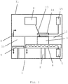
- the Figure 1 shows in a purely schematic representation a device 1 of the type that can be used, for example, for selective laser melting for the additive manufacturing of a component and in particular a moving blade.
- the device 1 comprises a lifting table 2, on the platform of which a semifinished product 3 is arranged, on which material is deposited in layers in order to produce a three-dimensional component in the form of a moving blade for a turbomachine.
- powder 10 which is located in a powder supply above a lifting table 9, is pushed in layers over the semi-finished product 3 by means of the slide 8 and then connected to the already existing semi-finished product 3 by the laser beam 13 of a laser 4 by melting.
- the connection of the powder material in a powder layer with the semifinished product 3 is carried out by the laser 4 depending on the desired contour of the component to be manufactured, so that any three-dimensional shapes can be produced.
- the laser beam is corresponding 13 guided over the powder bed 12 in order to melt powder material through different impingement points on the powder bed according to the contour of the three-dimensional component in the cutting plane corresponding to the layer plane produced and to connect it to the part of a component already produced or to an initially provided substrate.
- the laser beam 13 can be guided over the surface of the powder bed 12 by a suitable deflection unit and / or the powder bed could be moved with respect to the laser beam 13.
- the process can take place in a closed space, which is provided by a housing 11 of the device 1, and an inert gas atmosphere can also be provided, for example to oxidize the powder material and to avoid the like when separating.
- an inert gas atmosphere can also be provided, for example to oxidize the powder material and to avoid the like when separating.
- nitrogen can be used as the inert gas, which is provided via a gas supply, not shown.
- an electrical resistance heater with a resistance heating control 5 and an electric heating wire 6 is provided in the lifting table, so that the powder bed 12 and the component 3 are heated to a desired temperature from below by appropriate heating can be preheated and / or a desired temperature gradient, in particular with respect to the layer being processed on the surface of the powder bed, can be set.
- heating is provided with a heating device from the top of the powder bed 12 and the component 3 already created, which in the exemplary embodiment shown is formed by an induction heater with an induction coil 14 and an induction heating controller 15.
- the induction coil 14 surrounds the laser beam 13 and, if necessary, can be moved parallel to the surface of the powder bed 12 in accordance with the laser beam 13.
- any other type of heating that enables heating of the powder bed 12 and / or the component 3 that has already been produced from the top side can also be provided, such as, for example, radiant heating devices such as infrared radiators and the like.
- the resistance heater 5, 6 can also be replaced by suitable other types of heating which enable the powder bed 12 and the component 3 already produced to be heated from below.
- further heating devices can be provided surrounding the already produced component 3 and / or the powder bed 12 in order to enable lateral heating of the powder bed 12 and / or the already produced component 3.
- cooling devices or combined heating / cooling devices can also be provided, so that, in addition to heating the already produced component 3 and the powder bed 12, targeted cooling can also be carried out, in order thereby to maintain the temperature balance in the powder bed 12 and / or the generated component 3, in particular with regard to the powder layer melted by the laser beam 13 and the solidification front on the melted powder material in a targeted manner.
- the component can be subdivided into at least two component areas, which are made of the same material with regard to the chemical composition, but are formed with different structures by using different powders and / or process parameters in additive manufacturing. For this purpose, only when changing from one component area to another component area, a corresponding exchange of the powder material and / or a change in the deposition parameters have to be carried out when carrying out the additive manufacturing process.
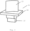
- the Figure 2 shows a blade 21 of a turbomachine with an airfoil 22 and a blade root 23 and an inner shroud 24 arranged between the airfoil 22 and blade root 23.
- the blade 21 is formed, for example, from a Ni-based superalloy, as is known for example under the trade name IN 718 .
- Ni-based super alloys or other high-temperature alloys such as Fe-based super alloys or Co-based super alloys are also conceivable.
- the blade 21 is made additively from a powder material of the Ni base superalloy by selective laser beam melting, for example with a device Fig. 1 formed, whereby The blade 21 is formed in layers corresponding to the cross section of the blade 21 in a corresponding build-up layer on the part of the blade 21 that has already been produced by melting and solidifying powder from the Ni base superalloy. As a result, the entire blade 21 is built up in layers from the Ni base superalloys.
- two component areas of the blade 21 are formed in different ways in order to thereby produce different microstructures and thus different property profiles in the two component areas.
- the first component area is formed by the blade root 22, in which area a structure of the Ni base superalloy with fine grain carbide precipitates which is as fine as possible is formed in order to set an advantageous fatigue behavior with a high fatigue strength. This can be achieved by choosing a fine-grained starting powder for the additive manufacture of the blade 21 than for the manufacture of the remaining part of the blade 21.
- the process parameters in the additive manufacture such as to choose a higher construction speed in the area of the blade root 22 than in the rest of the blade 21 to be formed, so that more solidification nuclei are formed, and thus a finer one, due to the higher melt energy introduced and the short residence time of the laser beam for melting the powder and a higher cooling rate when the melt solidifies Microstructure can be set as in the remaining area of the blade 21.
- the airfoil 3 and / or the inner shroud 4 or the transition area between the airfoil 3 and the inner shroud 4 can be defined as a second component area, in which by using a coarser starting powder and / or adapted process parameters in additive manufacturing, for example with regard to a slower rate Build-up speed with slower melting, longer dwell time of the laser beam in the area of the melted powder and thus longer holding time of the powder in the melted state and slow cooling, a coarser structure with larger carbide precipitates than in the first component area or further component areas can be set, which leads to the fact that creep resistance is improved.
- 22 grain sizes up to a maximum of 500 ⁇ m, preferably up to 100 ⁇ m can be set in the area of the blade root, while the carbide precipitates can have a maximum size of 30 ⁇ m, preferably a maximum of 10 ⁇ m, while Grain sizes of over 500 ⁇ m are possible in the second component area in the area of the airfoil.
- the grain size can be determined as the mean grain size according to known grain size determination methods or as the maximum extent of the grains in one direction.
Abstract
Die vorliegende Erfindung betrifft ein Verfahren zur Herstellung eines Bauteils (21) einer Strömungsmaschine aus einer Metalllegierung sowie ein entsprechend hergestelltes Bauteil, wobei das Verfahren folgende Schritte umfasst:Definieren von mindestens einem ersten Bauteilbereich (22), der ein erstes Eigenschaftsprofil aufweisen soll, und von mindestens einem zweiten Bauteilbereich (23,24), der ein zweites Eigenschaftsprofil aufweisen soll, welches von dem ersten Eigenschaftsprofil unterschiedlich ist, Bereitstellen mindestens eines Pulvers aus der Metalllegierung oder von mehreren unterschiedlichen Pulvern von Bestandteilen der Metalllegierung,additive Fertigung des Bauteils (21) aus dem mindestens einen Pulver, wobei das Pulver zur stoffschlüssigen Verbindung der Pulverpartikel untereinander und mit einem Substrat oder einem bereits hergestellten Teil des Bauteils aufgeschmolzen wird und wobei die Pulverpartikel zur Ausbildung des ersten Bauteilbereichs und die Pulverpartikel zur Ausbildung des zweiten Bauteilbereichs unterschiedlich sind und / oder unter derart unterschiedlichen Bedingungen additiv abgeschieden werden, sodass sich im ersten Bauteilbereich und im zweiten Bauteilbereich unterschiedliche Gefüge des abgeschiedenen Materials ergeben.The invention relates to a method for producing a component (21) of a fluid flow machine from a metal alloy and a component that is produced accordingly, the method comprising the following steps: defining at least one first component region (22) which is to have a first property profile, and at least one second component area (23, 24), which is to have a second property profile that is different from the first property profile, providing at least one powder from the metal alloy or from several different powders from components of the metal alloy, additive manufacturing of the component (21) the at least one powder, the powder for the integral connection of the powder particles to one another and with a substrate or an already produced part of the component being melted, and with the powder particles for forming the first component region and the powder particles for out Formation of the second component area are different and / or are additively deposited under such different conditions, so that different structures of the deposited material result in the first component area and in the second component area.
Description
Die vorliegende Erfindung betrifft ein Verfahren zur Herstellung eines Bauteils einer Strömungsmaschine aus einer Metalllegierung, insbesondere einer Schaufel einer Gas - oder Flugturbine sowie ein entsprechend hergestelltes Bauteil, insbesondere eine Laufschaufel einer Gas - oder Flugturbine aus einer Ni - Basislegierung.The present invention relates to a method for producing a component of a turbomachine from a metal alloy, in particular a blade of a gas or aircraft turbine, and to a correspondingly manufactured component, in particular a moving blade of a gas or aircraft turbine from a Ni - based alloy.
Es ist im Stand der Technik bekannt, in Strömungsmaschinen, wie stationären Gasturbinen oder Flugturbinen, Bauteile, die hohen mechanischen Belastungen und hohen Temperaturen sowie aggressiven Medien ausgesetzt sind, zumindest teilweise aus hochwarmfesten Legierungen, wie beispielsweise Ni -, Fe - oder Co - Basislegierungen und insbesondere entsprechenden Superlegierungen zu bilden. Insbesondere Laufschaufeln, die bei hohen Betriebstemperaturen aufgrund der auftretenden Fliehkräfte hohen mechanischen Belastungen ausgesetzt sind, werden üblicherweise aus Ni - Basissuperlegierungen gebildet.It is known in the state of the art, in turbomachines, such as stationary gas turbines or aviation turbines, components which are exposed to high mechanical loads and high temperatures and aggressive media, at least partially from high-temperature alloys, such as Ni, Fe or Co base alloys and in particular to form corresponding superalloys. In particular, blades that are exposed to high mechanical loads at high operating temperatures due to the centrifugal forces that occur are usually formed from Ni-based superalloys.
Unter Basislegierungen werden Legierungen verstanden, deren Hauptbestandteil das angegebene Element, wie z.B. Nickel, ist und die zusätzliche Legierungsbestandteile aufweisen, um ein gewünschtes Eigenschaftsprofil aufweisen. Unter Superlegierungen werden entsprechende Basislegierungen verstanden, die eine Zusammensetzung mit zahlreichen Legierungsbestandteilen zur Ausbildung einer komplexen Gefügestruktur aufweisen, wie beispielsweise Chrom, Molybdän, Titan, Aluminium, Niob, Eisen und Kohlenstoff im Falle von Ni - Basissuperlegierungen, um durch Bildung von Ausscheidungen hohe Festigkeitswerte zu erzielen.Base alloys are understood to be alloys whose main constituent is the specified element, such as nickel, and which have additional alloy constituents in order to have a desired property profile. Superalloys are understood to mean corresponding base alloys which have a composition with numerous alloy components to form a complex microstructure, such as, for example, chromium, molybdenum, titanium, aluminum, niobium, iron and carbon in the case of Ni base superalloys, in order to achieve high strength values through the formation of precipitates achieve.
Üblicherweise werden beispielsweise Laufschaufeln aus Ni - Basissuperlegierungen, wie z.B. die unter der Handelsbezeichnung IN 718 bekannte Legierung, durch Feingussverfahren endkonturnah hergestellt. Allerdings bedingt die Geometrie der Laufschaufeln mit einem eher großvolumigen Schaufelfuß und einem eher dünn dimensionierten Schaufelblatt bzw. Deckband im Übergangsbereich zwischen Schaufelfuß und Schaufelblatt, dass in den dünnwandigen Bereichen ein feinkörniges Gefüge durch eine hohe Abkühlungsrate und die dadurch bedingte hohe Keimbildungsrate erzeugt wird, während im großvolumigen Bereich des Schaufelfußes mit geringerer Abkühlungsrate und geringerer Keimbildungsrate ein grobkörniges Gefüge gebildet wird. Auch Ausscheidungen, wie Karbide, werden im großvolumigen Bereich eher mit größerer Korngröße gebildet, während in Bereichen der Laufschaufeln mit dünnerem Querschnitt feinkörnige Ausscheidungen, wie Karbide, gebildet werden.For example, blades made of Ni base super alloys, such as e.g. the alloy known under the trade name IN 718, produced by investment casting near the net shape. However, the geometry of the blades with a rather large-volume blade root and a rather thinly dimensioned blade blade or shroud in the transition area between the blade root and blade blade means that in the thin-walled areas a fine-grained structure is generated by a high cooling rate and the resulting high nucleation rate, while in large area of the blade root with a lower cooling rate and lower nucleation rate a coarse-grained structure is formed. Excretions, such as carbides, are also formed with a larger grain size in the large-volume area, while fine-grained precipitates, such as carbides, are formed in areas of the rotor blades with a thinner cross section.
Allerdings ist es für den Einsatz der Laufschaufeln eher von Interesse eine andere Gefügeausbildung vorzusehen, da die grobkörnige Ausbildung im Schaufelfußbereich zu ungünstigen Ermüdungseigenschaften in diesem Bereich der Laufschaufeln führt, während die feinkörnige Gefüge Ausbildung im Schaufelblattbereich einen ungünstigen Einfluss auf die Kriechbeständigkeit der Laufschaufeln aufweist. Die ungünstige Gefügeausbildung bei der Herstellung durch Feinguss kann gemäß dem Stand der Technik nur durch aufwändige Wärmebehandlungsverfahren beseitigt werden.However, it is of more interest to provide a different microstructure for the use of the blades, since the coarse-grained structure in the blade root area leads to unfavorable fatigue properties in this area of the blades, while the fine-grained microstructure in the airfoil area has an unfavorable influence on the creep resistance of the blades. According to the prior art, the unfavorable microstructure during the production by investment casting can only be eliminated by complex heat treatment processes.
Es ist deshalb Aufgabe der vorliegenden Erfindung ein Verfahren zur Herstellung von Bauteilen eine Strömungsmaschine und insbesondere von Laufschaufeln aus Ni - Basislegierungen bereitzustellen, bei welchem ein günstiges Eigenschaftsprofil in einfacher Weise eingestellt werden kann. Insbesondere soll eine Laufschaufeln hergestellt werden können, welche im Fußbereich gute Ermüdungseigenschaften und insbesondere eine hohe Ermüdungsfestigkeit aufweist, während im Schaufelblattbereich bzw. im Bereich eines Deckbandes eine gute Kriechbeständigkeit gegeben sein soll. Zudem soll das Herstellungsverfahren einfach und zuverlässig anwendbar sein.It is therefore an object of the present invention to provide a method for producing components of a turbomachine and in particular of rotor blades made of Ni-based alloys, in which a favorable property profile can be set in a simple manner. In particular, it should be possible to produce a rotor blade which has good fatigue properties in the foot region and in particular a high fatigue strength, while in the airfoil region or in the region of a shroud it has good creep resistance should be given. In addition, the manufacturing process should be simple and reliable to use.
Diese Aufgabe wird gelöst durch ein Verfahren mit den Merkmalen des Anspruchs 1 sowie ein Bauteil mit den Merkmalen des Anspruchs 12. Vorteilhafte Ausgestaltungen sind Gegenstand der abhängigen Ansprüche.This object is achieved by a method having the features of
Die Erfindung schlägt für eine endkonturnahe Herstellung eines Bauteils einer Strömungsmaschine und insbesondere einer Laufschaufeln einer stationären Gasturbine oder einer Flugturbine vor, das Bauteil durch ein additives Fertigungsverfahren, auch generatives Herstellungsverfahren genannt, herzustellen. Bei einem derartigen Verfahren, wie beispielsweise dem selektiven Laserstrahlschmelzen, dem selektiven Laserstrahlsintern, dem selektiven Elektronenstrahlschmelzen, dem selektiven Elektronenstrahlsintern oder dem Auftragsschweißen wird das Bauteil aus mindestens einem Pulver lagenweise aufgebaut, indem das Pulver entsprechend der Querschnittsform in der gerade aufzubauenden Ebene stoffschlüssig und insbesondere durch Aufschmelzen der Pulverpartikel und anschließendes Erstarren mit einem Substrat bzw. einem bereits hergestellten Teil des Bauteils verbunden wird. Um unterschiedliche Eigenschaftsprofile in dem Bauteil zu erreichen, wird die additive Fertigung in verschiedenen Bauteilbereichen, die verschiedene Eigenschaftsprofile aufweisen sollen, mit unterschiedlichen Pulverpartikeln und / oder unterschiedlichen Prozessparametern durchgeführt, sodass sich in den unterschiedlichen Bauteilbereichen, die unterschiedliche Eigenschaften aufweisen sollen, unterschiedliche Gefüge des abgeschiedenen Materials ausbilden. Dadurch kann trotz der einstückigen und homogenen Ausbildung des Bauteils aus einem Werkstoff mit gleicher chemischer Zusammensetzung eine unterschiedliche Ausbildung von Eigenschaften über dem Bauteil erreicht werden.For a near-net-shape production of a component of a turbomachine, and in particular of a moving blade of a stationary gas turbine or an aircraft turbine, the invention proposes to produce the component by means of an additive manufacturing process, also called a generative manufacturing process. In such a method, such as, for example, selective laser beam melting, selective laser beam sintering, selective electron beam melting, selective electron beam sintering or cladding, the component is built up in layers from at least one powder in that the powder is cohesive and in particular through the cross-sectional shape in the plane to be built up Melting the powder particles and subsequent solidification is connected to a substrate or an already produced part of the component. In order to achieve different property profiles in the component, additive manufacturing is carried out in different component areas, which should have different property profiles, with different powder particles and / or different process parameters, so that in the different component areas, which should have different properties, different structures of the deposited Train materials. In this way, despite the one-piece and homogeneous formation of the component from a material with the same chemical composition, a different formation of properties can be achieved over the component.
Entsprechend kann zunächst bei der Herstellung des Bauteils mindestens eine erster Bauteilbereich definiert werden, wie beispielsweise der Fußbereich einer Laufschaufel, der ein erstes Eigenschaftsprofil aufweisen soll, wie beispielsweise eine hohe Ermüdungsfestigkeit. Darüber hinaus kann mindestens ein zweiter Bauteilbereich definiert werden, der ein zweites Eigenschaftsprofil aufweisen soll, welches sich von dem ersten Eigenschaftsprofile unterscheidet, wobei es sich beispielsweise um den Bereich des Schaufelblatts handeln kann, welches eine hohe Kriechfestigkeit aufweisen soll.Correspondingly, at least one first component area can first be defined during the production of the component, such as, for example, the root area of a moving blade, which should have a first property profile, such as high fatigue strength, for example. In addition, at least one second component area can be defined, which has a second property profile Should have, which differs from the first property profile, which may be, for example, the area of the airfoil, which should have a high creep resistance.
Für die additive Fertigung wird dann entsprechend mindestens ein Pulver aus der Metalllegierung, aus der das Bauteil einstückig gefertigt werden soll, bereitgestellt. Es können jedoch auch mehrere unterschiedliche Pulver verwendet werden, die sich beispielsweise in ihrer chemischen Zusammensetzung und / oder in der Größenverteilung der Pulverpartikel unterscheiden.At least one powder of the metal alloy from which the component is to be manufactured in one piece is then correspondingly provided for additive manufacturing. However, several different powders can also be used, which differ, for example, in their chemical composition and / or in the size distribution of the powder particles.
Obwohl das Bauteil üblicherweise homogen aus einem Werkstoff mit gleicher chemischer Zusammensetzung gebildet sein kann, können Pulver mit unterschiedlicher chemischer Zusammensetzung eingesetzt werden, wobei durch die unterschiedlichen Pulver der Werkstoff, aus dem das Bauteil hergestellt werden soll, bei der Herstellung legiert wird. Allerdings kann auch bereits ein fertig legiertes Pulver, also Pulverpartikel mit der gleichen chemischen Zusammensetzung wie das herzustellende Bauteil Verwendung finden.Although the component can usually be formed homogeneously from a material with the same chemical composition, powders with a different chemical composition can be used, the different powders being used to alloy the material from which the component is to be manufactured. However, a fully alloyed powder, i.e. powder particles with the same chemical composition as the component to be manufactured, can also be used.
Hinsichtlich ihrer Größenverteilung unterschiedliche Pulverpartikel können eingesetzt werden, um unterschiedliche Gefüge in den verschiedenen Bauteilbereichen, also dem mindestens einen ersten Bauteilbereich und dem mindestens einen zweiten Bauteilbereich, und somit unterschiedliche Eigenschaften in den Bauteilbereichen einzustellen.Different powder particles can be used with regard to their size distribution in order to set different structures in the different component areas, that is to say the at least one first component area and the at least one second component area, and thus different properties in the component areas.
Zusätzlich oder alternativ ist es möglich zur Einstellung verschiedener Gefüge in den verschiedenen Bauteilbereichen die Abscheideparameter bzw. Prozessparameter für die additive Herstellung in diesen Bauteilbereichen unterschiedlich einzustellen.Additionally or alternatively, it is possible to set the deposition parameters or process parameters for additive manufacturing in these component areas differently in order to set different structures in the different component areas.
So können in Abhängigkeit von dem verwendeten additiven Verfahren eine Vielzahl verschiedener Parameter verwendet werden, um unterschiedliche Gefügeausbildungen und somit unterschiedliche Eigenschaftsprofile in den verschiedenen Bauteilbereichen einzustellen. Insbesondere kann die Aufheizenergie, die zum Aufheizen bzw. Schmelzen der Pulverpartikel eingesetzt wird, in den verschiedenen Bauteilbereichen unterschiedlich gewählt werden. Beispielsweise kann die Strahlenergie, mit der ein Laser - oder Elektronenstrahl auf das aufzuschmelze Pulver gerichtet wird, unterschiedlich gewählt werden. Auch die Vorschubgeschwindigkeit und somit die Verweildauer beispielsweise eines hochenergetischen Strahls in einem bestimmten Pulverbereich kann variiert werden. Ferner können die Aufschmelztemperaturen oder die Vorwärmtemperaturen des Pulvermaterials, welches vor dem Aufschmelzen beispielsweise durch Strahlungsheizung oder induktive Heizung vorgewärmt kann werden kann, können zur Einstellung unterschiedlicher Gefüge verändert werden, genauso wie die Haltezeiten des Pulvers im aufgeschmolzenen Zustand. Zudem ist es möglich unterschiedliche Aufschmelzraten und unterschiedliche Abkühlbedingungen mit unterschiedlichen Abkühlgeschwindigkeiten sowie unterschiedlichen Temperaturgradienten in den verschiedenen Bauteilbereichen bei der additiven Fertigung einzustellen. Auch weitere Parameter, wie beispielsweise ein unterschiedlicher Umgebungsdruck der umgebenden Atmosphäre, unterschiedliche Zusammensetzung der umgebenden Atmosphäre können für die gezielte Einstellung eines Gefüges eingestellt werden. Auch die allgemeine Abscheidegeschwindigkeit der einzelnen Lagen in den verschiedenen Bauteilbereichen kann unterschiedlich gewählt werden, wie beispielsweise durch verschiedene Vorschubgeschwindigkeiten eines hochenergetischen Strahls, beispielsweise eines Laserstrahls oder Elektronenstrahls zum Aufschmelzen des Pulvers, oder unterschiedlichen Materialflüssen beim Auftragsschweißen.Depending on the additive method used, a large number of different parameters can be used to set different microstructures and thus different property profiles in the different component areas. In particular, the heating energy used to heat or melt the powder particles can be selected differently in the different component areas. For example, the beam energy with which a laser or electron beam is directed onto the powder to be melted can be selected differently. The feed rate and thus the dwell time of, for example, a high-energy jet in a specific powder area can be varied. Furthermore, the melting temperatures or the preheating temperatures of the powder material, which can be preheated before melting, for example by radiation heating or inductive heating, can be changed to adjust different structures, as can the holding times of the powder in the melted state. It is also possible to set different melting rates and different cooling conditions with different cooling speeds and different temperature gradients in the different component areas during additive manufacturing. Other parameters, such as a different ambient pressure of the surrounding atmosphere, different composition of the surrounding atmosphere can also be set for the targeted setting of a structure. The general deposition speed of the individual layers in the different component areas can also be selected differently, for example by means of different feed speeds of a high-energy beam, for example a laser beam or electron beam for melting the powder, or different material flows during build-up welding.
Die eingesetzten Pulverpartikel und / oder die Prozessparameter der additiven Herstellung können nicht nur zwischen einem ersten Bauteilbereich und einem zweiten Bauteilbereich unterschiedlich vorgesehen sein, sondern können auch innerhalb des ersten und / oder zweiten Bauteilbereichs oder im Bereich der Übergänge zwischen dem ersten und dem zweiten Bauteilbereich variieren, sodass im ersten und / oder zweiten Bauteilbereich und oder im Übergangsbereich zwischen erstem Bauteilbereich und zweitem Bauteilbereich ein Gradientenwerkstoff mit kontinuierlich variierendem Eigenschaftsprofil aufgrund einer kontinuierlich sich verändernden Gefügeausbildung erzeugt werden kann.The powder particles used and / or the process parameters of the additive manufacturing can not only be provided differently between a first component area and a second component area, but can also vary within the first and / or second component area or in the area of the transitions between the first and the second component area , so that in the first and / or second component area and or in the transition area between the first component area and the second component area, a gradient material with a continuously varying property profile can be generated due to a continuously changing structure.
Auf diese Weise lässt sich insbesondere eine Schaufel und insbesondere eine Laufschaufel einer Strömungsmaschine mit einem angepassten Eigenschaftsprofil herstellen, wobei beispielsweise im Schaufelfußbereich ein Gefüge eingestellt werden kann, welches eine verbesserte Ermüdungseigenschaft aufweist, während im Schaufelblattbereich oder im Bereich eines Deckbands eine verbesserte Kriechfestigkeit durch ein entsprechendes Gefüge eingestellt werden kann. Für diesen Fall können beispielsweise im ersten Bauteilbereich, welcher einem Schaufelfuß entspricht, ein feinkörniges Gefüge mit feinen Karbidausscheidungen und im zweiten Bauteilbereich, der dem Schaufelblatt und / oder einem Deckband entspricht, ein grobkörniges Gefüge mit groben Karbidausscheidungen gebildet werden. Neben Karbiden können auch andere Ausscheidungen oder Partikel, wie beispielsweise Oxide oder ähnliche Verbindungen, Verwendung finden.In this way, in particular a blade and in particular a rotor blade of a turbomachine with an adapted property profile can be produced, it being possible, for example, to set a structure in the blade root area which has an improved fatigue property, while in the airfoil area or in the area of a shroud an improved creep resistance due to a corresponding Structure can be adjusted. In this case, for example, in the first component area, which corresponds to a blade root, a fine-grained structure with fine carbide deposits and in the second component area, which corresponds to the airfoil and / or a shroud, can also have a coarse-grain structure coarse carbide precipitates are formed. In addition to carbides, other precipitates or particles, such as oxides or similar compounds, can also be used.
Die beigefügten Zeichnungen zeigen in rein schematischer Weise in
- Fig.1
- eine schematische Darstellung einer Vorrichtung zur generativen Herstellung von Bauteilen am Beispiel des selektiven Laserschmelzens und in
- Fig. 2
- eine Darstellung einer Turbinenschaufel, die entsprechend dem erfindungsgemäßen Verfahren hergestellt wird.
- Fig. 1
- a schematic representation of a device for the additive manufacturing of components using the example of selective laser melting and in
- Fig. 2
- an illustration of a turbine blade, which is produced according to the inventive method.
Weitere Vorteile, Kennzeichen und Merkmale der vorliegenden Erfindung werden bei der nachfolgenden detaillierten Beschreibung der Ausführungsbeispiele ersichtlich. Allerdings ist die Erfindung nicht auf diese Ausführungsbeispiele beschränkt.Further advantages, characteristics and features of the present invention will become apparent from the following detailed description of the exemplary embodiments. However, the invention is not restricted to these exemplary embodiments.
Die
Um unerwünschte Reaktionen mit der Umgebungsatmosphäre beim Aufschmelzen oder Sintern zu vermeiden, kann der Prozess in einem abgeschlossenen Raum, der durch ein Gehäuse 11 der Vorrichtung 1 bereit gestellt wird, stattfinden und es kann zudem eine inerte Gasatmosphäre bereit gestellt werden, um beispielsweise Oxidation des Pulvermaterials und dergleichen beim Abscheiden zu vermeiden. Als inertes Gas kann beispielsweise Stickstoff verwendet werden, welches über eine nicht dargestellte Gasversorgung bereitgestellt wird.In order to avoid undesirable reactions with the ambient atmosphere during melting or sintering, the process can take place in a closed space, which is provided by a
Anstelle des Inertgases könnte auch ein anderes Prozessgas verwendet werden, wenn beispielsweise eine reaktive Abscheidung des Pulvermaterials gewünscht ist.Instead of the inert gas, another process gas could also be used if, for example, reactive deposition of the powder material is desired.
Darüber hinaus sind auch andere Strahlungsarten denkbar, wie beispielsweise Elektronenstrahlen oder andere Teilchenstrahlen oder Lichtstrahlen, die bei der Stereolithographie eingesetzt werden.In addition, other types of radiation are also conceivable, such as electron beams or other particle beams or light beams that are used in stereolithography.
Zur Einstellung der gewünschten Temperaturen im erzeugten Bauteil 3 und / oder im Pulverbett 12 ist im Hubtisch eine elektrische Widerstandsheizung mit einer Widerstandsheizungssteuerung 5 und einem elektrischen Heizdraht 6 vorgesehen, so dass das Pulverbett 12 und das Bauteil 3 durch entsprechendes Erwärmen von unten auf eine gewünschte Temperatur vorerwärmt werden können und / oder ein gewünschter Temperaturgradient, insbesondere zu der gerade bearbeiteten Schicht an der Oberfläche des Pulverbetts, eingestellt werden kann. In ähnlicher Weise ist eine Beheizung mit einer Heizungseinrichtung von der Oberseite des Pulverbetts 12 und des bereits erstellten Bauteils 3 vorgesehen, die bei dem gezeigten Ausführungsbeispiel durch eine Induktionsheizung mit einer Induktionsspule 14 und einer Induktionsheizungssteuerung 15 gebildet ist. Die Induktionsspule 14 umgibt hierbei den Laserstrahl 13 und ist bei Bedarf parallel zur Oberfläche des Pulverbetts 12 entsprechend dem Laserstrahl 13 bewegbar.To set the desired temperatures in the
Anstelle der dargestellten Induktionsheizung kann auch jede andere Heizungsart, die eine Erwärmung des Pulverbetts 12 und / oder des bereits erzeugten Bauteils 3 von der Oberseite ermöglicht, vorgesehen werden, wie beispielsweise Strahlungsheizgeräte, wie Infrarotstrahler und dergleichen. In gleicher Weise kann auch die Widerstandsheizung 5, 6 durch geeignete andere Heizungsarten, die eine Erwärmung des Pulverbetts 12 und des bereits erzeugten Bauteils 3 von unten ermöglichen, ersetzt werden. Darüber hinaus können weitere Heizeinrichtungen umgebend um das bereits erzeugte Bauteil 3 und / oder das Pulverbett 12 vorgesehen werden, um eine seitliche Erwärmung des Pulverbetts 12 und / oder des bereits erzeugten Bauteils 3 zu ermöglichen.Instead of the induction heating shown, any other type of heating that enables heating of the
Neben Heizeinrichtungen können auch Kühleinrichtungen oder kombinierte Heiz - / Kühleinrichtungen vorgesehen werden, um neben einer Erwärmung des bereits erzeugten Bauteils 3 und des Pulverbetts 12 auch eine gezielte Abkühlung vornehmen zu können, um dadurch den Temperaturhaushalt im Pulverbett 12 und / oder dem erzeugten Bauteil 3, insbesondere in Bezug auf die durch den Laserstrahl 13 aufgeschmolzene Pulverschicht und die Erstarrungsfront an dem aufgeschmolzenem Pulvermaterial gezielt einstellen und beeinflussen zu können.In addition to heating devices, cooling devices or combined heating / cooling devices can also be provided, so that, in addition to heating the already produced
Erfindungsgemäß kann das Bauteil in mindestens zwei Bauteilbereiche unterteilt sein, die zwar bezüglich der chemischen Zusammensetzung aus dem gleichen Werkstoff aufgebaut sind, aber durch Verwendung unterschiedlicher Pulver und / oder Prozessparameter bei der additiven Fertigung mit unterschiedlichen Gefügen ausgebildet werden. Hierzu muss lediglich beim Wechsel von einem Bauteilbereich zum anderen Bauteilbereich ein entsprechender Austausch des Pulvermaterials und / oder eine Änderung der Abscheideparameter bei der Durchführung des additiven Herstellungsprozesses vorgenommen werden.According to the invention, the component can be subdivided into at least two component areas, which are made of the same material with regard to the chemical composition, but are formed with different structures by using different powders and / or process parameters in additive manufacturing. For this purpose, only when changing from one component area to another component area, a corresponding exchange of the powder material and / or a change in the deposition parameters have to be carried out when carrying out the additive manufacturing process.
Die
Die Schaufel 21 ist additiv aus einem Pulvermaterial der Ni - Basissuperlegierung durch selektives Laserstrahlschmelzen beispielsweise mit einer Vorrichtung aus
Gemäß der Erfindung werden jedoch zwei Bauteilbereiche der Schaufel 21 in unterschiedlicher Art und Weise gebildet, um dadurch in den beiden Bauteilbereichen unterschiedliche Gefügeausbildungen und somit unterschiedliche Eigenschaftsprofile zu erzeugen.According to the invention, however, two component areas of the
Der erste Bauteilbereich wird durch den Schaufelfuß 22 gebildet, wobei in diesem Bereich ein möglichst feinkörniges Gefüge der Ni - Basissuperlegierung mit feinkörnigen Karbid - Ausscheidungen gebildet wird, um ein vorteilhaftes Ermüdungsverhalten mit einer hohen Ermüdungsfestigkeit einzustellen. Dies kann dadurch erreicht werden, dass ein feinkörniges Ausgangspulver für die additive Herstellung der Schaufel 21 gewählt wird als für die Herstellung des restlichen Teils der Schaufel 21. Alternativ oder zusätzlich ist es auch möglich, die Prozessparameter bei der additiven Herstellung geeignet zu wählen, wie z.B. die Baugeschwindigkeit im Bereich des Schaufelfußes 22 höher zu wählen als im Rest der zu bildenden Schaufel 21, sodass aufgrund höherer, eingebrachter Schmelzenergie sowie kurzer Verweildauer des Laserstrahls zum Aufschmelzen des Pulvers und einer höheren Abkühlungsrate beim Erstarren der Schmelze mehr Erstarrungskeime gebildet werden und somit ein feineres Gefüge eingestellt werden kann als im übrigen Bereich der Schaufel 21.The first component area is formed by the
Entsprechend können das Schaufelblatt 3 und / oder das innere Deckband 4 bzw. der Übergangsbereich zwischen Schaufelblatt 3 und innerem Deckband 4 als ein zweiter Bauteilbereich definiert werden, in welchem durch Verwendung eines gröberen Ausgangspulvers und / oder angepasster Prozessparameter bei der additiven Fertigung z.B. hinsichtlich einer langsameren Aufbaugeschwindigkeit mit langsamerem Aufschmelzen, längerer Verweildauer des Laserstrahls im Bereich des aufgeschmolzenen Pulvers und somit längerer Haltedauer des Pulvers im aufgeschmolzenen Zustand sowie langsamer Abkühlung ein gröberes Gefüge mit größeren Karbid - Ausscheidungen als im ersten Bauteilbereich oder weiteren Bauteilbereichen eingestellt werden kann, was dazu führt, dass die Kriechbeständigkeit verbessert wird.Accordingly, the
So können beispielsweise bei einer Ni - Basissuperlegierungen im ersten Bauteilbereich im Bereich des Schaufelfußes 22 Korngrößen bis maximal 500 µm, vorzugsweise bis maximal 100 µm eingestellt werden, während die Karbid - Ausscheidungen eine maximale Größe von 30 µm, vorzugsweise maximal 10 µm aufweisen können, während im zweiten Bauteilbereich im Bereich des Schaufelblatts Korngrößen von über 500 µm möglich sind. Die Korngröße kann hierbei als mittlere Korngröße gemäß bekannter Korngrößenbestimmungsverfahren oder als die maximale Erstreckung der Körner in einer Richtung ermittelt werden.For example, in the case of a Ni base superalloy in the first component area, 22 grain sizes up to a maximum of 500 µm, preferably up to 100 µm can be set in the area of the blade root, while the carbide precipitates can have a maximum size of 30 µm, preferably a maximum of 10 µm, while Grain sizes of over 500 µm are possible in the second component area in the area of the airfoil. The grain size can be determined as the mean grain size according to known grain size determination methods or as the maximum extent of the grains in one direction.
Obwohl die vorliegende Erfindung anhand der Ausführungsbeispiele detailliert beschrieben worden ist, ist für den Fachmann selbstverständlich, dass die Erfindung nicht auf diese Ausführungsbeispiele beschränkt ist, sondern dass vielmehr Abwandlungen in der Weise möglich sind, dass einzelne Merkmale weggelassen oder andersartige Kombinationen von Merkmalen verwirklicht werden können, ohne dass der Schutzbereich der beigefügten Ansprüche verlassen wird. Insbesondere schließt die vorliegende Offenbarung sämtliche Kombinationen der in den verschiedenen Ausführungsbeispielen gezeigten Einzelmerkmale mit ein, sodass einzelne Merkmale, die nur in Zusammenhang mit einem Ausführungsbeispiel beschrieben sind, auch bei anderen Ausführungsbeispielen oder nicht explizit dargestellten Kombinationen von Einzelmerkmalen eingesetzt werden können.Although the present invention has been described in detail with reference to the exemplary embodiments, it is obvious to the person skilled in the art that the invention is not restricted to these exemplary embodiments, but rather that modifications are possible in such a way that individual features can be omitted or other types of combinations of features can be implemented without departing from the scope of the appended claims. In particular, the present disclosure includes all combinations of the individual features shown in the various exemplary embodiments, so that individual features that are only described in connection with one exemplary embodiment can also be used in other exemplary embodiments or combinations of individual features that are not explicitly illustrated.
- 11
- Vorrichtungcontraption
- 22nd
- HubtischLift table
- 33rd
- Halbzeug bzw. hergestelltes BauteilSemi-finished or manufactured component
- 44th
- Laserlaser
- 55
- WiderstandsheizungssteuerungResistance heating control
- 66
- HeizdrahtHeating wire
- 88th
- SchieberSlider
- 99
- HubtischLift table
- 1010th
- Pulverpowder
- 1111
- Gehäusecasing
- 1212th
- PulverbettPowder bed
- 1313
- Laserstrahllaser beam
- 1414
- InduktionsspuleInduction coil
- 1515
- InduktionsheizungssteuerungInduction heating control
- 2121
- Schaufelshovel
- 2222
- SchaufelfußBlade root
- 2323
- SchaufelblattAirfoil
- 2424th
- DeckbandShroud
Claims (15)
dadurch gekennzeichnet, dass
bei der additiven Fertigung das Bauteil (3,21) schichtweise auf einem Substrat oder einem vorher erzeugten Teil des Bauteils aufgebaut wird, wobei ein schichtweiser Aufbau durch lagenweises Auftragsschweißen oder lagenweises Aufschmelzen von Pulvermaterial mit einem energiereichen Strahl und lagenweises Erstarren der Pulverschmelze erfolgt.Method according to claim 1,
characterized in that
In additive manufacturing, the component (3, 21) is built up in layers on a substrate or a previously generated part of the component, a layer-by-layer construction being carried out by layer-by-layer welding or layer-by-layer melting of powder material with a high-energy beam and layer-by-layer solidification of the powder melt.
dadurch gekennzeichnet, dass
der energiereiche Strahl ein Laser - oder Elektronenstrahl ist.Method according to claim 2,
characterized in that
the high energy beam is a laser or electron beam.
dadurch gekennzeichnet, dass
vor dem Aufschmelzen eine Vorwärmung des Pulvermaterials (10) erfolgt, insbesondere durch Strahlungsheizung oder induktiver Heizung.Method according to one of the preceding claims,
characterized in that
before melting, the powder material (10) is preheated, in particular by radiant heating or inductive heating.
dadurch gekennzeichnet, dass
die unterschiedlichen Bedingungen zum Aufschmelzen des Pulvers mindestens eine Komponente aus der Gruppe umfassen, die unterschiedliche Aufheizenergie, unterschiedliche Strahlenergie, unterschiedliche Aufschmelztemperaturen, unterschiedliche Aufschmelzraten, unterschiedliche Vorwärmzeiten, unterschiedliche Haltezeiten im aufgeschmolzenem Zustand, unterschiedliche Abkühlbedingungen, unterschiedliche Abkühlgeschwindigkeiten, unterschiedliche Temperaturgradienten, unterschiedliche Umgebungsdrücke und unterschiedliche Abscheidegeschwindigkeiten aufweisen.Method according to one of the preceding claims,
characterized in that
the different conditions for melting the powder comprise at least one component from the group which has different heating energy, different radiation energy, different melting temperatures, different melting rates, different preheating times, different holding times in the molten state, different cooling conditions, different cooling speeds, different temperature gradients, different ambient pressures and different Have separation speeds.
dadurch gekennzeichnet, dass
das Bauteil im ersten Bauteilbereich (22) und im zweiten Bauteilbereich (23,24) aus einer Metalllegierung gleicher chemischer Zusammensetzung gebildet wird.Method according to one of the preceding claims,
characterized in that
the component in the first component region (22) and in the second component region (23, 24) is formed from a metal alloy of the same chemical composition.
dadurch gekennzeichnet, dass
die unterschiedlichen Pulverpartikel und / oder die unterschiedlichen Bedingungen zum Aufschmelzen des Pulvers bei der Herstellung des ersten und / oder des zweiten Bauteilbereichs über den entsprechenden ersten und / oder den zweiten Bauteilbereich und / oder im Übergangsbereich zwischen dem ersten und zweiten Bauteilbereich so variiert werden, dass im entsprechenden ersten und / oder zweiten Bauteilbereich und / oder im Übergangsbereich ein Gradientenwerkstoff mit variierendem Eigenschaftsprofil abgeschieden wird.Method according to one of the preceding claims,
characterized in that
the different powder particles and / or the different conditions for melting the powder during the production of the first and / or the second component region via the corresponding first and / or the second component region and / or in the transition region between the first and second component regions are varied such that A gradient material with a varying property profile is deposited in the corresponding first and / or second component area and / or in the transition area.
dadurch gekennzeichnet, dass
das Eigenschaftsprofil des ersten Bauteilbereichs (22) eine verbesserte Ermüdungsfestigkeit als im zweiten Bauteilbereich umfasst und / oder dass das Eigenschaftsprofil im zweiten Bauteilbereich (23,24) eine höhere Kriechfestigkeit als im ersten Bauteilbereich umfasst.Method according to one of the preceding claims,
characterized in that
the property profile of the first component area (22) an improved fatigue strength than in the second component area and / or that the property profile in the second component area (23, 24) comprises a higher creep resistance than in the first component area.
dadurch gekennzeichnet, dass
das Bauteil eine Schaufel (21) einer Strömungsmaschine, insbesondere eine Laufschaufel ist, wobei der erste Bauteilbereich den Schaufelfuß (22) umfasst und der zweite Bauteilbereich den Bereich eines inneren und / oder äußeren Deckbands (24) und / oder den Bereich des Schaufelblatts (23) und / oder den Übergangsbereich zwischen Deckband und Schaufelblatt umfasst.Method according to one of the preceding claims,
characterized in that
the component is a blade (21) of a turbomachine, in particular a moving blade, the first component area comprising the blade root (22) and the second component area the area of an inner and / or outer shroud (24) and / or the area of the airfoil (23 ) and / or the transition area between the shroud and the airfoil.
dadurch gekennzeichnet, dass
das Bauteil aus einer Fe - , Co - oder Ni - Basissuperlegierung gebildet ist.Method according to one of the preceding claims,
characterized in that
the component is formed from an Fe, Co or Ni base super alloy.
dadurch gekennzeichnet, dass
im ersten Bauteilbereich (22) ein feinkörniges Gefüge mit feinen Ausscheidungen, insbesondere Karbidausscheidungen, und / oder im zweiten Bauteilbereich (23,24) ein grobkörniges Gefüge mit groben Ausscheidungen, insbesondere Karbidausscheidungen ausgebildet wird.Method according to one of the preceding claims,
characterized in that
a fine-grained structure with fine precipitates, in particular carbide precipitates, and / or a coarse-grained structure with coarse precipitates, in particular carbide precipitates, is formed in the first component area (22).
dadurch gekennzeichnet, dass
das Bauteil eine Schaufel (21) einer Strömungsmaschine, insbesondere eine Laufschaufel ist, wobei der erste Bauteilbereich den Schaufelfuß (22) umfasst und der zweite Bauteilbereich den Bereich eines inneren und / oder äußeren Deckbands (24) und / oder den Bereich des Schaufelblatts (23) und / oder den Übergangsbereich zwischen Deckband und Schaufelblatt umfasst.Component according to claim 12,
characterized in that
the component is a blade (21) of a turbomachine, in particular a moving blade, the first component area comprising the blade root (22) and the second component area the area of an inner and / or outer shroud (24) and / or the area of the airfoil (23 ) and / or the transition area between the shroud and the airfoil.
dadurch gekennzeichnet, dass
das Eigenschaftsprofil des ersten Bauteilbereichs (22) eine verbesserte Ermüdungsfestigkeit als im zweiten Bauteilbereich (23,24) umfasst und / oder dass das Eigenschaftsprofil im zweiten Bauteilbereich (23,24) eine höhere Kriechfestigkeit als im ersten Bauteilbereich (22) umfasst.Component according to claim 12 or 13,
characterized in that
the property profile of the first component area (22) comprises improved fatigue strength than in the second component area (23, 24) and / or that the property profile in the second component area (23, 24) comprises a higher creep resistance than in the first component area (22).
dadurch gekennzeichnet, dass
im ersten Bauteilbereich (22) ein feinkörniges Gefüge mit feinen Ausscheidungen, insbesondere Karbidausscheidungen und / oder im zweiten Bauteilbereich (23,24) ein grobkörniges Gefüge mit groben Ausscheidungen, insbesondere Karbidausscheidungen ausgebildet ist.Component according to one of Claims 12 to 14,
characterized in that
a fine-grained structure with fine precipitates, in particular carbide precipitates, and / or a coarse-grained structure with coarse precipitates, in particular carbide precipitates, is formed in the first component area (22).
Applications Claiming Priority (1)
| Application Number | Priority Date | Filing Date | Title |
|---|---|---|---|
| DE102019200620.5A DE102019200620A1 (en) | 2019-01-18 | 2019-01-18 | Process for the production of rotor blades made of Ni-based alloys and rotor blade produced accordingly |
Publications (1)
| Publication Number | Publication Date |
|---|---|
| EP3682988A1 true EP3682988A1 (en) | 2020-07-22 |
Family
ID=69159565
Family Applications (1)
| Application Number | Title | Priority Date | Filing Date |
|---|---|---|---|
| EP20151270.4A Pending EP3682988A1 (en) | 2019-01-18 | 2020-01-10 | Method for producing rotor blades from ni base alloys and rotor blade produced according to said method |
Country Status (3)
| Country | Link |
|---|---|
| US (1) | US20200230744A1 (en) |
| EP (1) | EP3682988A1 (en) |
| DE (1) | DE102019200620A1 (en) |
Cited By (1)
| Publication number | Priority date | Publication date | Assignee | Title |
|---|---|---|---|---|
| EP4186617A1 (en) * | 2021-11-26 | 2023-05-31 | MTU Aero Engines AG | Method for producing an impact-resistant component and corresponding impact-resistant component |
Families Citing this family (3)
| Publication number | Priority date | Publication date | Assignee | Title |
|---|---|---|---|---|
| US11951566B2 (en) * | 2019-07-31 | 2024-04-09 | General Electric Company | Assignment of multiple print parameter sets in additive manufacturing |
| US11701832B2 (en) * | 2020-02-26 | 2023-07-18 | Wisconsin Alumni Research Foundation | Systems and methods for controlling additive manufacturing systems |
| CN116160204B (en) * | 2023-04-17 | 2023-06-23 | 中国空气动力研究与发展中心超高速空气动力研究所 | Optimized manufacturing method of hypersonic high-temperature wind tunnel water-cooling heat insulation device |
Citations (3)
| Publication number | Priority date | Publication date | Assignee | Title |
|---|---|---|---|---|
| US20140255198A1 (en) * | 2013-03-11 | 2014-09-11 | United Technologies Corporation | Turbine disk fabrication with in situ material property variation |
| DE102015102397A1 (en) * | 2014-02-25 | 2015-08-27 | General Electric Company | System with a layered structure and method for its production |
| EP3238863A1 (en) * | 2016-04-27 | 2017-11-01 | MTU Aero Engines GmbH | Method for producing a rotor blade for a fluid flow engine |
Family Cites Families (11)
| Publication number | Priority date | Publication date | Assignee | Title |
|---|---|---|---|---|
| US4851055A (en) * | 1988-05-06 | 1989-07-25 | The United States Of America As Represented By The Secretary Of The Air Force | Method of making titanium alloy articles having distinct microstructural regions corresponding to high creep and fatigue resistance |
| US5451142A (en) * | 1994-03-29 | 1995-09-19 | United Technologies Corporation | Turbine engine blade having a zone of fine grains of a high strength composition at the blade root surface |
| DE102007059865A1 (en) * | 2007-12-12 | 2009-06-18 | Bayerische Motoren Werke Aktiengesellschaft | Producing a mold body by structuring powder forming metallic material in layered manner, comprises subjecting layers one upon the other and melting each powder layer before bringing the powder layer with a wave like high energy radiation |
| EP2799179A1 (en) * | 2013-04-29 | 2014-11-05 | Siemens Aktiengesellschaft | Generative method for creating an end joint and end joint |
| WO2015053946A1 (en) * | 2013-10-09 | 2015-04-16 | United Technologies Corporation | Multi-density, multi-property turbine component |
| US20160318104A1 (en) * | 2013-12-20 | 2016-11-03 | United Technologies Corporation | Gradient sintered metal preform |
| KR102383340B1 (en) * | 2014-07-21 | 2022-04-07 | 누보 피그노네 에스알엘 | Method for manufacturing machine components by additive manufacturing |
| DE102016203785A1 (en) * | 2016-03-08 | 2017-09-14 | MTU Aero Engines AG | Method for producing a blade for a turbomachine |
| DE102016206558A1 (en) * | 2016-04-19 | 2017-10-19 | MTU Aero Engines AG | Method and device for producing at least one component region of a component |
| FR3058457B1 (en) * | 2016-11-10 | 2018-12-07 | Safran Helicopter Engines | PROCESS FOR PRODUCING A TURBOMACHINE BLADE |
| US10710159B2 (en) * | 2017-09-06 | 2020-07-14 | General Electric Company | Apparatus and method for additive manufacturing with real-time and in-situ adjustment of growth parameters |
-
2019
- 2019-01-18 DE DE102019200620.5A patent/DE102019200620A1/en active Pending
-
2020
- 2020-01-10 EP EP20151270.4A patent/EP3682988A1/en active Pending
- 2020-01-16 US US16/744,337 patent/US20200230744A1/en active Pending
Patent Citations (3)
| Publication number | Priority date | Publication date | Assignee | Title |
|---|---|---|---|---|
| US20140255198A1 (en) * | 2013-03-11 | 2014-09-11 | United Technologies Corporation | Turbine disk fabrication with in situ material property variation |
| DE102015102397A1 (en) * | 2014-02-25 | 2015-08-27 | General Electric Company | System with a layered structure and method for its production |
| EP3238863A1 (en) * | 2016-04-27 | 2017-11-01 | MTU Aero Engines GmbH | Method for producing a rotor blade for a fluid flow engine |
Cited By (1)
| Publication number | Priority date | Publication date | Assignee | Title |
|---|---|---|---|---|
| EP4186617A1 (en) * | 2021-11-26 | 2023-05-31 | MTU Aero Engines AG | Method for producing an impact-resistant component and corresponding impact-resistant component |
Also Published As
| Publication number | Publication date |
|---|---|
| US20200230744A1 (en) | 2020-07-23 |
| DE102019200620A1 (en) | 2020-07-23 |
Similar Documents
| Publication | Publication Date | Title |
|---|---|---|
| EP3682988A1 (en) | Method for producing rotor blades from ni base alloys and rotor blade produced according to said method | |
| EP3216547B1 (en) | Method for producing a rotor blade for a fluid flow engine | |
| EP3069803A1 (en) | Blade for a turbine engine made from different materials and method for producing the same | |
| DE102009051479A1 (en) | Method and device for producing a component of a turbomachine | |
| CH705750A1 (en) | A process for the production of components or portions, which consist of a high-temperature superalloy. | |
| DE102010046468B4 (en) | Generative manufacturing process and powder for this purpose | |
| EP3731985B1 (en) | Method for additive manufacturing a component with oxide dispersion strengthening and corresponding component | |
| DE102007059865A1 (en) | Producing a mold body by structuring powder forming metallic material in layered manner, comprises subjecting layers one upon the other and melting each powder layer before bringing the powder layer with a wave like high energy radiation | |
| WO2011020462A1 (en) | Thin-walled structural component, and method for the production thereof | |
| EP3372700B1 (en) | Method for making forged tial components | |
| Breidenstein et al. | Effect of post-process machining on surface properties of additively manufactured H13 tool steel | |
| DE102015115963A1 (en) | Method and apparatus for the additive production of a shaped body from a metallic material mixture | |
| EP3249064A1 (en) | Additive manufacture of high temperature components from tial | |
| DE102016113246A1 (en) | Method and device for producing a metallic material mixture in additive manufacturing | |
| DE102016201836A1 (en) | Device for a plant for the additive production of a component | |
| DE102014222526A1 (en) | Method and device for the generative production of at least one component region of a component | |
| DE102019219133A1 (en) | Additive manufacturing process | |
| DE102010055791A1 (en) | Process for the manufacture of components made of refractory metals | |
| WO2019228663A1 (en) | Method for developing forging materials | |
| WO2022105967A1 (en) | Method for producing a component from an alloy, and correspondingly produced component | |
| EP3414034A1 (en) | Pre-treatment, method for additive production of a component, and device | |
| EP1570098A2 (en) | Method for the production of a part having improved weldability and/or mechanical processability from an alloy | |
| WO2017194275A1 (en) | Construction platform for additive manufacturing, and method | |
| DE102018114911A1 (en) | POWDER PREPARATION SYSTEM AND METHOD FOR ADDITIVE MANUFACTURE | |
| DE102018203877A1 (en) | METHOD FOR GENERATIVELY MANUFACTURING COMPONENTS FROM MATERIAL-HARDENED MATERIALS |
Legal Events
| Date | Code | Title | Description |
|---|---|---|---|
| PUAI | Public reference made under article 153(3) epc to a published international application that has entered the european phase |
Free format text: ORIGINAL CODE: 0009012 |
|
| STAA | Information on the status of an ep patent application or granted ep patent |
Free format text: STATUS: THE APPLICATION HAS BEEN PUBLISHED |
|
| AK | Designated contracting states |
Kind code of ref document: A1 Designated state(s): AL AT BE BG CH CY CZ DE DK EE ES FI FR GB GR HR HU IE IS IT LI LT LU LV MC MK MT NL NO PL PT RO RS SE SI SK SM TR |
|
| AX | Request for extension of the european patent |
Extension state: BA ME |
|
| STAA | Information on the status of an ep patent application or granted ep patent |
Free format text: STATUS: REQUEST FOR EXAMINATION WAS MADE |
|
| 17P | Request for examination filed |
Effective date: 20210108 |
|
| RBV | Designated contracting states (corrected) |
Designated state(s): AL AT BE BG CH CY CZ DE DK EE ES FI FR GB GR HR HU IE IS IT LI LT LU LV MC MK MT NL NO PL PT RO RS SE SI SK SM TR |
|
| STAA | Information on the status of an ep patent application or granted ep patent |
Free format text: STATUS: EXAMINATION IS IN PROGRESS |
|
| 17Q | First examination report despatched |
Effective date: 20210521 |