EP3682935B1 - Step feature for steerable guidewires - Google Patents
Step feature for steerable guidewires Download PDFInfo
- Publication number
- EP3682935B1 EP3682935B1 EP20163100.9A EP20163100A EP3682935B1 EP 3682935 B1 EP3682935 B1 EP 3682935B1 EP 20163100 A EP20163100 A EP 20163100A EP 3682935 B1 EP3682935 B1 EP 3682935B1
- Authority
- EP
- European Patent Office
- Prior art keywords
- guidewire
- self
- catheter
- expanding element
- diameter
- Prior art date
- Legal status (The legal status is an assumption and is not a legal conclusion. Google has not performed a legal analysis and makes no representation as to the accuracy of the status listed.)
- Active
Links
- 229920003266 Leaf® Polymers 0.000 claims description 8
- 235000014443 Pyrus communis Nutrition 0.000 claims description 3
- 230000007423 decrease Effects 0.000 claims description 3
- 238000000034 method Methods 0.000 description 12
- 239000000463 material Substances 0.000 description 4
- 241000124008 Mammalia Species 0.000 description 2
- 238000006073 displacement reaction Methods 0.000 description 2
- 230000006870 function Effects 0.000 description 2
- 229910001000 nickel titanium Inorganic materials 0.000 description 2
- 230000009466 transformation Effects 0.000 description 2
- 230000002792 vascular Effects 0.000 description 2
- 210000005166 vasculature Anatomy 0.000 description 2
- 206010002329 Aneurysm Diseases 0.000 description 1
- 208000007536 Thrombosis Diseases 0.000 description 1
- 238000002399 angioplasty Methods 0.000 description 1
- 230000001419 dependent effect Effects 0.000 description 1
- 230000003073 embolic effect Effects 0.000 description 1
- 238000002594 fluoroscopy Methods 0.000 description 1
- 238000003384 imaging method Methods 0.000 description 1
- 238000013152 interventional procedure Methods 0.000 description 1
- 239000003550 marker Substances 0.000 description 1
- 229910052751 metal Inorganic materials 0.000 description 1
- 239000002184 metal Substances 0.000 description 1
- HLXZNVUGXRDIFK-UHFFFAOYSA-N nickel titanium Chemical compound [Ti].[Ti].[Ti].[Ti].[Ti].[Ti].[Ti].[Ti].[Ti].[Ti].[Ti].[Ni].[Ni].[Ni].[Ni].[Ni].[Ni].[Ni].[Ni].[Ni].[Ni].[Ni].[Ni].[Ni].[Ni] HLXZNVUGXRDIFK-UHFFFAOYSA-N 0.000 description 1
- 230000002265 prevention Effects 0.000 description 1
- 238000001356 surgical procedure Methods 0.000 description 1
- 230000001225 therapeutic effect Effects 0.000 description 1
Images


Classifications
-
- A—HUMAN NECESSITIES
- A61—MEDICAL OR VETERINARY SCIENCE; HYGIENE
- A61M—DEVICES FOR INTRODUCING MEDIA INTO, OR ONTO, THE BODY; DEVICES FOR TRANSDUCING BODY MEDIA OR FOR TAKING MEDIA FROM THE BODY; DEVICES FOR PRODUCING OR ENDING SLEEP OR STUPOR
- A61M25/00—Catheters; Hollow probes
- A61M25/01—Introducing, guiding, advancing, emplacing or holding catheters
- A61M25/09—Guide wires
-
- A—HUMAN NECESSITIES
- A61—MEDICAL OR VETERINARY SCIENCE; HYGIENE
- A61M—DEVICES FOR INTRODUCING MEDIA INTO, OR ONTO, THE BODY; DEVICES FOR TRANSDUCING BODY MEDIA OR FOR TAKING MEDIA FROM THE BODY; DEVICES FOR PRODUCING OR ENDING SLEEP OR STUPOR
- A61M25/00—Catheters; Hollow probes
- A61M25/01—Introducing, guiding, advancing, emplacing or holding catheters
- A61M2025/0177—Introducing, guiding, advancing, emplacing or holding catheters having external means for receiving guide wires, wires or stiffening members, e.g. loops, clamps or lateral tubes
-
- A—HUMAN NECESSITIES
- A61—MEDICAL OR VETERINARY SCIENCE; HYGIENE
- A61M—DEVICES FOR INTRODUCING MEDIA INTO, OR ONTO, THE BODY; DEVICES FOR TRANSDUCING BODY MEDIA OR FOR TAKING MEDIA FROM THE BODY; DEVICES FOR PRODUCING OR ENDING SLEEP OR STUPOR
- A61M25/00—Catheters; Hollow probes
- A61M25/01—Introducing, guiding, advancing, emplacing or holding catheters
- A61M25/09—Guide wires
- A61M2025/09125—Device for locking a guide wire in a fixed position with respect to the catheter or the human body
-
- A—HUMAN NECESSITIES
- A61—MEDICAL OR VETERINARY SCIENCE; HYGIENE
- A61M—DEVICES FOR INTRODUCING MEDIA INTO, OR ONTO, THE BODY; DEVICES FOR TRANSDUCING BODY MEDIA OR FOR TAKING MEDIA FROM THE BODY; DEVICES FOR PRODUCING OR ENDING SLEEP OR STUPOR
- A61M25/00—Catheters; Hollow probes
- A61M25/01—Introducing, guiding, advancing, emplacing or holding catheters
- A61M25/09—Guide wires
- A61M2025/09175—Guide wires having specific characteristics at the distal tip
- A61M2025/09183—Guide wires having specific characteristics at the distal tip having tools at the distal tip
-
- A—HUMAN NECESSITIES
- A61—MEDICAL OR VETERINARY SCIENCE; HYGIENE
- A61M—DEVICES FOR INTRODUCING MEDIA INTO, OR ONTO, THE BODY; DEVICES FOR TRANSDUCING BODY MEDIA OR FOR TAKING MEDIA FROM THE BODY; DEVICES FOR PRODUCING OR ENDING SLEEP OR STUPOR
- A61M25/00—Catheters; Hollow probes
- A61M25/10—Balloon catheters
- A61M25/1002—Balloon catheters characterised by balloon shape
- A61M2025/1004—Balloons with folds, e.g. folded or multifolded
-
- A—HUMAN NECESSITIES
- A61—MEDICAL OR VETERINARY SCIENCE; HYGIENE
- A61M—DEVICES FOR INTRODUCING MEDIA INTO, OR ONTO, THE BODY; DEVICES FOR TRANSDUCING BODY MEDIA OR FOR TAKING MEDIA FROM THE BODY; DEVICES FOR PRODUCING OR ENDING SLEEP OR STUPOR
- A61M25/00—Catheters; Hollow probes
- A61M25/01—Introducing, guiding, advancing, emplacing or holding catheters
- A61M25/0105—Steering means as part of the catheter or advancing means; Markers for positioning
- A61M25/0133—Tip steering devices
Definitions
- This invention relates to a self-expanding feature that can be integrated into a distal aspect of a guidewire to facilitate the crossing of a previously deployed device in the vasculature with a catheter or microcatheter.
- Figure 1A illustrates a microcatheter 2 with a guidewire 4, therethrough, hung up on a stent strut 6.
- Figure 1A is a forward view of the catheter 2 over the wire 4 crossing through the stent cell 10 and getting caught on the stent struts 6 (as in the case of an aneurysm coiling procedure) because of the difference in diameters of the guidewire 4 and the catheter 2.
- Figure 1B illustrates the ledge 8, as the difference between the outer diameter of the guidewire 4 and the outer diameter of the microcatheter 2.
- the ledge 8 distance can actually be greater as the guidewire 4 can be displaced from a center axis of the microcatheter 2, creating even more of a gap.
- Figure 1C illustrates the above problem.
- the stent cell 10 is placed within a body lumen (not illustrated) and the guidewire 4 is guided through the lumen.
- the microcatheter 2 is then advanced along the guidewire 4 and gets hung up on the stent strut 6 at the ledge 8.
- US2002161395A1 relates to a guide wire apparatus for prevention of distal atheroembolization during percutaneous catheter intervention procedures, such as angioplasty or stent deployment.
- An expandable protection element such as a self-expanding or self-collapsing filter or occluder, is mountable adjacent the distal end of a core wire, which can guide a therapeutic catheter. Relative displacement of the ends of the protection element causes transformation of the protection element between a closed configuration and an expanded configuration that spans the vessel to be treated.
- An operator rod which may be a hollow rod or an interventional catheter, may be slidably disposed over the core wire to engage with and either push or pull the proximal end of the protection element to cause transformation thereof.
- US2011276120A1 relates to a vascular device for use during an interventional procedure, the device having a stent structure having a collapsed configuration, an expanded configuration, a proximal end, and a distal end; and a delivery member for delivering the stent to a treatment site within a vasculature, wherein the proximal end of the stent structure is fixed to the delivery member when the stent structure is in the expanded configuration at the treatment site.
- US2003171771A1 relates to an embolic protection device or system for use in a lumen of a vessel in a patient's vascular system.
- the device filters debris and blood clots in a body lumen and/or prevents them from moving distally from a treatment site in a vessel and causing emboli.
- the device may include a filter placed distally of the treatment site.
- the device may include an occlusive element placed either distally or proximally of the treatment site.
- a mechanism to help prevent the ledge of the prior art includes a guidewire assembly as defined in claim 1.
- Figures 2-6 illustrate an example of a step feature for a guidewire 100 of the present invention.
- the guidewire 100 can have a core 102, which extends the length of the guidewire 100, and has a proximal end 104 and a distal end 106.
- the guidewire 100 and core 102 can be made of any material known to those of skill in the art for guidewires.
- the guidewire 100 has a guidewire diameter 108 so it can be directed through any size body lumen or passageway for a mammal.
- the guidewire 100 can be sized for neurovascular procedures.
- the guidewire diameter 108 is typically uniform across the length of the guidewire 100.
- the catheter 110 Disposed over the guidewire core 102 is a catheter/microcatheter 110.
- the catheter 110 has a catheter diameter 112 which is larger than the guidewire diameter 108, so that the guidewire 100 can pass through the inside 111 of the catheter 110.
- the catheter 110 is sized so it can be directed through any size body lumen or passageway for a mammal, and in one example it can be sized for neurovascular procedures.
- the catheter 110 is made out of materials known to those of skill in the art, and in one example, can be relatively soft and pliable.
- the guidewire comprises a self-expanding element disposed approximate to the distal end of the guidewire.
- a gap 114 can be formed between the proximal 104 and distal 106 ends of the guidewire 100 over which can be disposed the self-expanding element 116.
- the self-expanding element 116 is designed to expand and contract so as to increase and decrease its diameter.
- the self-expanding element 116 has a contracted diameter 118 which can be less than the catheter diameter 112 and, in one example, approximately equal to the guidewire diameter 108.
- the self-expanding element 116 typically has its contracted diameter 118 when disposed within the catheter 110. See, Figure 7A .
- the self-expanding element 116 also has an expanded diameter 120.
- the expanded diameter 120 can be greater than the guidewire diameter 108, and in one example, greater than the catheter diameter 112.
- the self-expanding element 116 can take its expanded diameter 120 once deployed from the catheter 110. See, Figure 7B .
- the expanded diameter 120 is such that it can diminish or remove the ledge 8, as seen in the prior art.
- the leaves 124 act as a "ramp" and this allows the guidewire 100 and catheter 110 to pass over the stent struts 6 of the stent cell 10, see Figure 8 .
- the self-expanding element 116 can be radially expandable from the contracted diameter 118, in one example where the element 116 is not greater in diameter 118 than the diameter of the guidewire shaft 108, to the expanded diameter 120, in which the diameter 120 of the element 116 is greater than that of the guidewire 108.
- the self-expanding element 116 is expandable under its inherent proprieties.
- the self-expanding element comprises a plurality of leaves, and in one example the self-expanding element 116 is a multi-leaf element.
- Each leaf 122 has the ability to flex so it can change shape and then return to its original shape. Thus the leaves 122 flex to allow the self-expanding element 116 to alternate between its contracted diameter 118 and expanded diameter 120.
- the self-expanding multi-leaf element 116 may be laser cut from a hypotube or fabricated from wires.
- the self-expanding element 116 may contain as few as three (3) or as many as twelve (12) leafs 122. In an example, some or all of the self-expanding multi-leaf element 116 can be radiopaque, allowing the surgeon to determine if the element 116 has been deployed from the catheter 110.
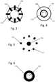
- Figures 3-6 illustrate the self-expanding element 116 in its deployed state.
- Figure 3 illustrates the leaves 122 creating the expanded diameter 120 greater than the catheter diameter 112.
- Figures 4-6 illustrate the self-expanding element 116 along the length of the gap 114 and how it can be, in an example, unfixed to the core 102.
- the self-expanding element 116 can also be secured directly to the core 102 near the proximal end 104. In this configuration the self-expanding clement 116 does not rotate or move axially over the core 102 (except for forward translation) but can be deployed into and out of the catheter 110.
- the self-expanding element 116 can rotate or move axially along the core 102 in the gap 114.
- the movement of the self-expanding element within the gap 114 can be controlled by a number of different features.
- an expansion/retraction bump 124 can be placed on the core 102 and under the leaves 122/self-expanding element 116.
- the expansion/retraction bumps 124 can have a larger outer diameter than an inner diameter of the leaves 122 on the self-expanding element 116. This can limit the amount of axial displacement of the self-expanding element 116.
- one or both of the expansion/retraction bumps 124 may be radiopaque.
- the self-expanding element 116 is constrained as shown on Fig. 7A .
- the self-expanding element 116 is located inside the microcatheter 110 by the mechanical interference between the larger distal expansion/retraction bump 124 and the distal self-expanding element leaf 122.
- the self-expanding element 116 opens once it is deployed out of the microcatheter 110, as shown in Figure 7B . Alignment of a radiopaque proximal expansion/retraction bump 124a with a catheter distal marker 110a can indicate that the self-expanding element 116 is fully opened.
- Figures 7C and 7D illustrate the self-expanding element 116 collapsing back into the microcatheter 110 by pulling on the guidewire 100 until the self-expanding element 116 is driven inside of the microcatheter 110 by the mechanical interference between the expansion/retraction bump 124.
- the self-expanding element 116 can be made from any spring or memory type metal or material.
- the material can be a nickel-titanium alloy (e.g. Nitinol).
- any element that can be expanded or contracted and deployed from a catheter can be used as the self-expanding element 116.
- an example of the expanded diameter 120 is that it can be 5-10% greater than the catheter diameter 112.
- the expanded diameter 120 can be greater than the outer diameter of the catheter, but not significantly so as to prevent the catheter and guidewire from passing through the chosen body lumen.
- the expanded diameter 120 can be compared to the guidewire diameter 108.
- the expanded diameter 120 can range between approximately 70% to 280% of the guidewire diameter depending on the combinations of guidewires and catheters.
- the shape of the self-expanding element 116 can be any shape that facilitates the passing of the catheter 110 over a stent strut 6. Examples of shapes are pear shaped, ovoid, and elliptical. Both the expanded diameter 120 and the shape of the self-expanding element 116 can be such that the leaves 122 are not designed to contact the walls of which ever body lumen the steerable wire 100 is passed through.
- the self-expanding element 116 does not assist in "centering" the guidewire/catheter system through the body lumen, on the contrary, the guidewire/catheter system needs some tolerance to the body lumen in order to move around the stent.
- the surgeon is typically aware that the patient has a previously deployed stent in the body lumen through which she needs to pass the guidewire and catheter.
- the surgeon can then choose to use the step feature for the steerable guidewire of the present invention.
- the self-expanding element 116 is typically deployed prior to reaching the stent, and its deployment verified using radio, X-ray or fluoroscopy imaging. Once the guidewire and catheter have passed the stent, and the catheter is in position for the new procedure, the surgeon can pull back on the guidewire, collapsing the self-expanding element, and fully remove the guidewire without complications from the element to proceed with the remainder of the surgical procedure.
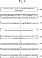
- Figure 9 illustrates a method, not being part of the invention, of advancing a steerable guidewire with a step function through a body lumen, which includes the step of providing a catheter 110 having a catheter diameter 112 that can form a guidewire lumen (step 200).
- a steerable guidewire 100 with a proximal end 104 and a distal end 106 having a self-expanding element 116 carried near the distal end 106 thereof can also be provided (step 202).
- the steerable guidewire 100 can be advanced through the guidewire lumen (step 204) and both the guidewire and catheter can be manipulated to locate the distal end 106 to a predetermined location in the body lumen (step 206).
- the steerable guidewire 100 is extended past the catheter 110 to expose the self-expanding element 116 (step 208).
- the self-expanding element 116 can be expanded to its expanded diameter 120 (step 210) and the steerable guidewire 100 and catheter can be advanced over the obstacle (step 212).
- the self-expanding element 116 can be contracted by retracting the steerable guidewire 100 back into the catheter 110 (step 214).
Description
- This invention relates to a self-expanding feature that can be integrated into a distal aspect of a guidewire to facilitate the crossing of a previously deployed device in the vasculature with a catheter or microcatheter.
- Crossing a previously deployed intravascular stent with a catheter over a guidewire presents a challenge, especially during neurovascular procedures. Often it is not possible to advance a catheter over the guidewire because of a ledge formed between the outer diameter of the guidewire and the outer diameter of the catheter.
Figure 1A illustrates amicrocatheter 2 with aguidewire 4, therethrough, hung up on astent strut 6.Figure 1A is a forward view of thecatheter 2 over thewire 4 crossing through thestent cell 10 and getting caught on the stent struts 6 (as in the case of an aneurysm coiling procedure) because of the difference in diameters of theguidewire 4 and thecatheter 2.Figure 1B illustrates theledge 8, as the difference between the outer diameter of theguidewire 4 and the outer diameter of themicrocatheter 2. The ledge 8 distance can actually be greater as theguidewire 4 can be displaced from a center axis of themicrocatheter 2, creating even more of a gap.Figure 1C illustrates the above problem. Thestent cell 10 is placed within a body lumen (not illustrated) and theguidewire 4 is guided through the lumen. Themicrocatheter 2 is then advanced along theguidewire 4 and gets hung up on thestent strut 6 at theledge 8. - Prior art attempts to solve this problem included "rounding" or "beveling" the tip of the catheter to facilitate tracking over the struts of the device. Additionally, a multi-catheter configuration has been tried in which catheters of progressively smaller diameters are inserted coaxially inside each other to minimize the ledge.
- What is needed is a simple mechanism to prevent the
ledge 8 from catching on thestent strut 6 while still being able to advance theguidewire 4 andmicrocatheter 2. -
US2002161395A1 relates to a guide wire apparatus for prevention of distal atheroembolization during percutaneous catheter intervention procedures, such as angioplasty or stent deployment. An expandable protection element, such as a self-expanding or self-collapsing filter or occluder, is mountable adjacent the distal end of a core wire, which can guide a therapeutic catheter. Relative displacement of the ends of the protection element causes transformation of the protection element between a closed configuration and an expanded configuration that spans the vessel to be treated. An operator rod, which may be a hollow rod or an interventional catheter, may be slidably disposed over the core wire to engage with and either push or pull the proximal end of the protection element to cause transformation thereof. -
US2011276120A1 relates to a vascular device for use during an interventional procedure, the device having a stent structure having a collapsed configuration, an expanded configuration, a proximal end, and a distal end; and a delivery member for delivering the stent to a treatment site within a vasculature, wherein the proximal end of the stent structure is fixed to the delivery member when the stent structure is in the expanded configuration at the treatment site. -
US2003171771A1 relates to an embolic protection device or system for use in a lumen of a vessel in a patient's vascular system. The device filters debris and blood clots in a body lumen and/or prevents them from moving distally from a treatment site in a vessel and causing emboli. The device may include a filter placed distally of the treatment site. The device may include an occlusive element placed either distally or proximally of the treatment site. - According to the invention, a mechanism to help prevent the ledge of the prior art includes a guidewire assembly as defined in claim 1.
- This invention provides a guidewire assembly according to the independent claim. Further embodiments of the invention are described in the dependent claims. The above and further aspects of this invention may be better understood by referring to the following description in conjunction with the accompanying drawings, in which like numerals indicate like structural elements and features in various figures. The drawings are not necessarily to scale, emphasis instead being placed upon illustrating the principles of the invention.
- The drawing figures depict one or more implementations in accord with the present teachings, by way of example only, not by way of limitation. In the figures, like reference numerals refer to the same or similar elements.
-
Figure 1A is a top perspective view of a known microcatheter and guidewire caught on a stent strut; -
Figure 1B is a side cross-section view of a known microcatheter and guidewire; -
Figure 1C is a side cross-section view of a known microcatheter and guidewire caught on a stent strut; -
Figure 2 is a side cross-section view of an example of a step feature for a guidewire of the present invention; -
Figure 3 is a front view of an example of a step feature for the guidewire of the present invention; -
Figure 4 is a cross-section view along line A-A ofFigure 2 ; -
Figure 5 is a cross-section view along line B-B ofFigure 2 ; -
Figure 6 is a cross-section view along line C-C ofFigure 2 ; -
Figures 7A-7D are side cross-section views of an example of a steerable guidewire being deployed and retracted; -
Figure 8 is a side cross-section view of an example of a microcatheter and guidewire of the present invention avoiding being caught on a stent strut; and -
Figure 9 is a flow chart of an example of a method, not being part of the invention, of using a step feature for a guidewire. - In the following detailed description, numerous specific details are set forth by way of examples in order to provide a thorough understanding of the relevant teachings. However, it should be apparent to those skilled in the art that the present teachings may be practiced without such details. In other instances, well known methods, procedures, components, and/or circuitry have been described at a relatively high-level, without detail, in order to avoid unnecessarily obscuring aspects of the present teachings.
-
Figures 2-6 illustrate an example of a step feature for aguidewire 100 of the present invention. Theguidewire 100 can have acore 102, which extends the length of theguidewire 100, and has aproximal end 104 and adistal end 106. Theguidewire 100 andcore 102 can be made of any material known to those of skill in the art for guidewires. Theguidewire 100 has aguidewire diameter 108 so it can be directed through any size body lumen or passageway for a mammal. In one example, theguidewire 100 can be sized for neurovascular procedures. In another example, theguidewire diameter 108 is typically uniform across the length of theguidewire 100. - Disposed over the
guidewire core 102 is a catheter/microcatheter 110. Thecatheter 110 has acatheter diameter 112 which is larger than theguidewire diameter 108, so that theguidewire 100 can pass through theinside 111 of thecatheter 110. As above, thecatheter 110 is sized so it can be directed through any size body lumen or passageway for a mammal, and in one example it can be sized for neurovascular procedures. Thecatheter 110 is made out of materials known to those of skill in the art, and in one example, can be relatively soft and pliable. - The guidewire comprises a self-expanding element disposed approximate to the distal end of the guidewire. A
gap 114 can be formed between the proximal 104 and distal 106 ends of theguidewire 100 over which can be disposed the self-expandingelement 116. The self-expandingelement 116 is designed to expand and contract so as to increase and decrease its diameter. The self-expandingelement 116 has a contracteddiameter 118 which can be less than thecatheter diameter 112 and, in one example, approximately equal to theguidewire diameter 108. The self-expandingelement 116 typically has its contracteddiameter 118 when disposed within thecatheter 110. See,Figure 7A . The self-expandingelement 116 also has an expandeddiameter 120. The expandeddiameter 120 can be greater than theguidewire diameter 108, and in one example, greater than thecatheter diameter 112. The self-expandingelement 116 can take its expandeddiameter 120 once deployed from thecatheter 110. See,Figure 7B . The expandeddiameter 120 is such that it can diminish or remove theledge 8, as seen in the prior art. Theleaves 124 act as a "ramp" and this allows theguidewire 100 andcatheter 110 to pass over the stent struts 6 of thestent cell 10, seeFigure 8 . - The self-expanding
element 116 can be radially expandable from the contracteddiameter 118, in one example where theelement 116 is not greater indiameter 118 than the diameter of theguidewire shaft 108, to the expandeddiameter 120, in which thediameter 120 of theelement 116 is greater than that of theguidewire 108. The self-expandingelement 116 is expandable under its inherent proprieties. - The self-expanding element comprises a plurality of leaves, and in one example the self-expanding
element 116 is a multi-leaf element. Eachleaf 122 has the ability to flex so it can change shape and then return to its original shape. Thus theleaves 122 flex to allow the self-expandingelement 116 to alternate between itscontracted diameter 118 and expandeddiameter 120. The self-expandingmulti-leaf element 116 may be laser cut from a hypotube or fabricated from wires. The self-expandingelement 116 may contain as few as three (3) or as many as twelve (12)leafs 122. In an example, some or all of the self-expandingmulti-leaf element 116 can be radiopaque, allowing the surgeon to determine if theelement 116 has been deployed from thecatheter 110. -
Figures 3-6 illustrate the self-expandingelement 116 in its deployed state.Figure 3 illustrates theleaves 122 creating the expandeddiameter 120 greater than thecatheter diameter 112.Figures 4-6 illustrate the self-expandingelement 116 along the length of thegap 114 and how it can be, in an example, unfixed to thecore 102. In a yet further example, the self-expandingelement 116 can also be secured directly to thecore 102 near theproximal end 104. In this configuration the self-expandingclement 116 does not rotate or move axially over the core 102 (except for forward translation) but can be deployed into and out of thecatheter 110. - In a further example, the self-expanding
element 116 can rotate or move axially along thecore 102 in thegap 114. The movement of the self-expanding element within thegap 114 can be controlled by a number of different features. In this example, an expansion/retraction bump 124 can be placed on thecore 102 and under theleaves 122/self-expandingelement 116. The expansion/retraction bumps 124 can have a larger outer diameter than an inner diameter of theleaves 122 on the self-expandingelement 116. This can limit the amount of axial displacement of the self-expandingelement 116. Additionally, one or both of the expansion/retraction bumps 124 may be radiopaque. - As illustrated in
Figures 7A-7D , while tracking theguidewire 100 inside of amicrocatheter 110, the self-expandingelement 116 is constrained as shown onFig. 7A . The self-expandingelement 116 is located inside themicrocatheter 110 by the mechanical interference between the larger distal expansion/retraction bump 124 and the distal self-expandingelement leaf 122. The self-expandingelement 116 opens once it is deployed out of themicrocatheter 110, as shown inFigure 7B . Alignment of a radiopaque proximal expansion/retraction bump 124a with a catheterdistal marker 110a can indicate that the self-expandingelement 116 is fully opened. Once deployed, theguidewire 100 andcatheter 110 can be advanced in tandem over thestent cell 10 without the potential for the catheter's 110 tip getting caught on the stent struts 6. CompareFigure 1C withFigure 8 . Note that thestent cell 10 could have been deployed during a previous procedure, and now the surgeon is performing a second procedure.Figures 7C and 7D illustrate the self-expandingelement 116 collapsing back into themicrocatheter 110 by pulling on theguidewire 100 until the self-expandingelement 116 is driven inside of themicrocatheter 110 by the mechanical interference between the expansion/retraction bump 124. - Another example of how the self-expanding
element 116 functions is that, in its rest position, theleaves 124 flex to the expandeddiameter 120. In this state, the overall length of the self-expandingelement 116 is L. As theleaves 124 are "flattened", that is to say straightened to a more parallel position, the length of the self-expandingelement 116 can be increased to L+. Thus, one or both of the ends of the self-expandingelement 116 translate along thecore 102. The self-expandingelement 116 can be made from any spring or memory type metal or material. In one example, the material can be a nickel-titanium alloy (e.g. Nitinol). However, any element that can be expanded or contracted and deployed from a catheter can be used as the self-expandingelement 116. Further, an example of the expandeddiameter 120 is that it can be 5-10% greater than thecatheter diameter 112. In examples, the expandeddiameter 120 can be greater than the outer diameter of the catheter, but not significantly so as to prevent the catheter and guidewire from passing through the chosen body lumen. - In other examples, the expanded
diameter 120 can be compared to theguidewire diameter 108. The expandeddiameter 120 can range between approximately 70% to 280% of the guidewire diameter depending on the combinations of guidewires and catheters. Additionally, the shape of the self-expandingelement 116 can be any shape that facilitates the passing of thecatheter 110 over astent strut 6. Examples of shapes are pear shaped, ovoid, and elliptical. Both the expandeddiameter 120 and the shape of the self-expandingelement 116 can be such that theleaves 122 are not designed to contact the walls of which ever body lumen thesteerable wire 100 is passed through. In an example, the self-expandingelement 116 does not assist in "centering" the guidewire/catheter system through the body lumen, on the contrary, the guidewire/catheter system needs some tolerance to the body lumen in order to move around the stent. - In use, the surgeon is typically aware that the patient has a previously deployed stent in the body lumen through which she needs to pass the guidewire and catheter. The surgeon can then choose to use the step feature for the steerable guidewire of the present invention. The self-expanding
element 116 is typically deployed prior to reaching the stent, and its deployment verified using radio, X-ray or fluoroscopy imaging. Once the guidewire and catheter have passed the stent, and the catheter is in position for the new procedure, the surgeon can pull back on the guidewire, collapsing the self-expanding element, and fully remove the guidewire without complications from the element to proceed with the remainder of the surgical procedure. -
Figure 9 illustrates a method, not being part of the invention, of advancing a steerable guidewire with a step function through a body lumen, which includes the step of providing acatheter 110 having acatheter diameter 112 that can form a guidewire lumen (step 200). Asteerable guidewire 100 with aproximal end 104 and adistal end 106 having a self-expandingelement 116 carried near thedistal end 106 thereof can also be provided (step 202). The steerable guidewire 100 can be advanced through the guidewire lumen (step 204) and both the guidewire and catheter can be manipulated to locate thedistal end 106 to a predetermined location in the body lumen (step 206). Either before or once an obstacle, such as astent 6, is encountered, thesteerable guidewire 100 is extended past thecatheter 110 to expose the self-expanding element 116 (step 208). The self-expandingelement 116 can be expanded to its expanded diameter 120 (step 210) and thesteerable guidewire 100 and catheter can be advanced over the obstacle (step 212). The self-expandingelement 116 can be contracted by retracting the steerable guidewire 100 back into the catheter 110 (step 214).
Claims (8)
- A guidewire assembly, comprising:a guidewire (100) comprising a proximal end (104), a distal end (106), and a diameter (108); anda self-expanding element (116) disposed approximate to the distal end of the guidewire and having a contracted diameter (118) and an expanded diameter (120), wherein the self-expanding element comprises a plurality of leafs (122);wherein the self-expanding element is expandable under its inherent proprietieswherein the guidewire is configured to be disposed in a catheter (110), and wherein the leafs are configured to act as a ramp allowing the guidewire and the catheter to pass over an obstacle (6) in a body lumen.
- A steerable catheter and guidewire system, comprising:the guidewire assembly of claim 1;a catheter (110) having a catheter inner diameter (112) forming a guidewire lumen and a catheter outer diameter; andwherein when the self-expanding element is disposed within the catheter, the self-expanding element has the contracted diameter,wherein when the self-expanding element is disposed outside the catheter, the self-expanding element has the expanded diameter.
- The guidewire assembly of claim 1, wherein the self-expanding element is at least one of pear shaped, ovoid, and elliptical when at its expanded diameter.
- The guidewire assembly of claim 1, further comprising a bump (124) disposed on the guidewire under the self-expanding element,wherein the self-expanding element is slideable along the guidewire;wherein the bump limits the slidability of the self-expanding element;wherein when the self-expanding element has the expanded diameter, a length of the self-expanding element decreases, and the bump limits the decrease in length and the expanded diameter.
- The steerable catheter and guidewire system of claim 2, wherein the expanded diameter is 5% to 10% greater than the catheter outer diameter.
- The steerable catheter and guidewire system of claim 2, wherein the self-expanding element is at least one of pear shaped, ovoid, and elliptical when at its expanded diameter.
- The steerable catheter and guidewire system of claim 2, wherein the self-expanding element contracted diameter permits the guidewire to be completely removed from the catheter.
- The guidewire assembly of claim 1, wherein the expanded diameter is 70% to 280% of the guidewire diameter.
Applications Claiming Priority (2)
| Application Number | Priority Date | Filing Date | Title |
|---|---|---|---|
| US14/454,780 US9993624B2 (en) | 2014-08-08 | 2014-08-08 | Step feature for steerable guidewires |
| EP15180176.8A EP2982407B1 (en) | 2014-08-08 | 2015-08-07 | Step feature for steerable guidewires |
Related Parent Applications (1)
| Application Number | Title | Priority Date | Filing Date |
|---|---|---|---|
| EP15180176.8A Division EP2982407B1 (en) | 2014-08-08 | 2015-08-07 | Step feature for steerable guidewires |
Publications (2)
| Publication Number | Publication Date |
|---|---|
| EP3682935A1 EP3682935A1 (en) | 2020-07-22 |
| EP3682935B1 true EP3682935B1 (en) | 2021-12-15 |
Family
ID=53794087
Family Applications (2)
| Application Number | Title | Priority Date | Filing Date |
|---|---|---|---|
| EP15180176.8A Active EP2982407B1 (en) | 2014-08-08 | 2015-08-07 | Step feature for steerable guidewires |
| EP20163100.9A Active EP3682935B1 (en) | 2014-08-08 | 2015-08-07 | Step feature for steerable guidewires |
Family Applications Before (1)
| Application Number | Title | Priority Date | Filing Date |
|---|---|---|---|
| EP15180176.8A Active EP2982407B1 (en) | 2014-08-08 | 2015-08-07 | Step feature for steerable guidewires |
Country Status (10)
| Country | Link |
|---|---|
| US (1) | US9993624B2 (en) |
| EP (2) | EP2982407B1 (en) |
| JP (2) | JP6656840B2 (en) |
| KR (1) | KR102623153B1 (en) |
| CN (1) | CN105363114B (en) |
| AU (2) | AU2015205964A1 (en) |
| BR (1) | BR102015018507B1 (en) |
| CA (1) | CA2899096C (en) |
| DK (1) | DK2982407T3 (en) |
| ES (2) | ES2790581T3 (en) |
Families Citing this family (7)
| Publication number | Priority date | Publication date | Assignee | Title |
|---|---|---|---|---|
| CN107405470A (en) * | 2015-02-11 | 2017-11-28 | 柯惠有限合伙公司 | With expansible sophisticated medical treatment device and method |
| JPWO2017203582A1 (en) | 2016-05-23 | 2019-04-11 | オリンパス株式会社 | Endoscope device and endoscope system |
| EP3519032A1 (en) * | 2016-09-30 | 2019-08-07 | PneumRx, Inc. | Guidewire |
| JP6734614B2 (en) * | 2017-04-06 | 2020-08-05 | 朝日インテック株式会社 | Tubular body and catheter equipped with the tubular body |
| US20200114129A1 (en) * | 2018-02-26 | 2020-04-16 | Horizon Patents, LLC | Guidewire for catheter insertion |
| CN113456986B (en) * | 2021-05-30 | 2023-04-28 | 为泰医疗器械(深圳)有限公司 | Double-cavity microcatheter for coronary intervention |
| WO2023086215A2 (en) * | 2021-11-10 | 2023-05-19 | St. Jude Medical, Cardiology Division, Inc. | Multi-lumen catheter containing integral strut and method of its manufacture |
Citations (2)
| Publication number | Priority date | Publication date | Assignee | Title |
|---|---|---|---|---|
| EP1524005A1 (en) * | 2003-10-14 | 2005-04-20 | Medtronic Vascular, Inc. | Steerable distal protection guidewire |
| WO2007033052A2 (en) * | 2005-09-12 | 2007-03-22 | Bridgepoint Medical, Inc. | Endovascular devices and methods for exploiting intramural space |
Family Cites Families (23)
| Publication number | Priority date | Publication date | Assignee | Title |
|---|---|---|---|---|
| US5002560A (en) * | 1989-09-08 | 1991-03-26 | Advanced Cardiovascular Systems, Inc. | Expandable cage catheter with a rotatable guide |
| US5265622A (en) | 1990-10-25 | 1993-11-30 | C. R. Bard, Inc. | Guidewire having radially expandable member and method for guiding and advancing a catheter using the same |
| US5447503A (en) | 1991-08-14 | 1995-09-05 | Cordis Corporation | Guiding catheter tip having a tapered tip with an expandable lumen |
| US5273052A (en) | 1992-01-08 | 1993-12-28 | Danforth Biomedical, Incorporated | Guidewire with reversible contact seal for releasable securement to catheter |
| US5497782A (en) | 1994-04-28 | 1996-03-12 | Medtronic, Inc. | Lockable guidewire |
| ES2210581T3 (en) * | 1996-09-18 | 2004-07-01 | Micro Therapeutics, Inc. | INTRACRANIAL EXTENSIONER. |
| US6336934B1 (en) * | 1997-11-07 | 2002-01-08 | Salviac Limited | Embolic protection device |
| US6468291B2 (en) * | 1999-07-16 | 2002-10-22 | Baff Llc | Emboli filtration system having integral strut arrangement and methods of use |
| ATE256436T1 (en) * | 1999-08-27 | 2004-01-15 | Ev3 Inc | SLIDING VASCULAR FILTER |
| JP3519656B2 (en) * | 2000-01-31 | 2004-04-19 | 株式会社シーアイメディック | Medical guidewire and balloon catheter |
| US20020161395A1 (en) * | 2001-04-03 | 2002-10-31 | Nareak Douk | Guide wire apparatus for prevention of distal atheroembolization |
| US7192434B2 (en) * | 2002-03-08 | 2007-03-20 | Ev3 Inc. | Vascular protection devices and methods of use |
| US6932829B2 (en) | 2002-06-24 | 2005-08-23 | Cordis Corporation | Centering catheter |
| US20040153119A1 (en) * | 2003-01-30 | 2004-08-05 | Kusleika Richard S. | Embolic filters with a distal loop or no loop |
| EP1618831A3 (en) * | 2004-06-29 | 2006-04-19 | Nippon Cable System Inc. | A moving device in pipe lines |
| US20060259063A1 (en) * | 2005-04-25 | 2006-11-16 | Bates Brian L | Wire guides having distal anchoring devices |
| US20070021685A1 (en) | 2005-05-04 | 2007-01-25 | Abbott Laboratories Abbott Vascular Devices | Guidewire apparatus with an expandable portion and methods of use |
| US8142468B2 (en) | 2005-12-22 | 2012-03-27 | Cordis Corporation | Guidewire with distal expansion feature and method for enhancing the deliverability and crossability of medical devices |
| US20090112126A1 (en) * | 2007-10-27 | 2009-04-30 | Salviac Limited | Stepped guidewire with shim |
| US20100268029A1 (en) * | 2009-04-21 | 2010-10-21 | Xlumena, Inc. | Methods and apparatus for advancing a device from one body lumen to another |
| US20120101560A1 (en) * | 2010-10-26 | 2012-04-26 | Kluck Bryan W | Retractable flow maintaining stent wire |
| BR112013011807A2 (en) * | 2010-11-15 | 2016-11-01 | Endovascular Dev Ab | '' set with guidewire and fixative for attachment to a blood vessel and tubular element '' |
| JP3173368U (en) * | 2011-11-22 | 2012-02-02 | アクセスポイント テクノロジーズ有限会社 | Guide wire guidance device |
-
2014
- 2014-08-08 US US14/454,780 patent/US9993624B2/en active Active
-
2015
- 2015-07-27 AU AU2015205964A patent/AU2015205964A1/en not_active Abandoned
- 2015-07-30 CA CA2899096A patent/CA2899096C/en active Active
- 2015-07-31 CN CN201510463323.9A patent/CN105363114B/en active Active
- 2015-07-31 BR BR102015018507-3A patent/BR102015018507B1/en active IP Right Grant
- 2015-08-03 KR KR1020150109411A patent/KR102623153B1/en active IP Right Grant
- 2015-08-07 EP EP15180176.8A patent/EP2982407B1/en active Active
- 2015-08-07 EP EP20163100.9A patent/EP3682935B1/en active Active
- 2015-08-07 ES ES15180176T patent/ES2790581T3/en active Active
- 2015-08-07 ES ES20163100T patent/ES2905180T3/en active Active
- 2015-08-07 DK DK15180176.8T patent/DK2982407T3/en active
- 2015-08-07 JP JP2015156984A patent/JP6656840B2/en active Active
-
2019
- 2019-07-05 JP JP2019125882A patent/JP6840793B2/en active Active
-
2020
- 2020-08-07 AU AU2020213372A patent/AU2020213372A1/en not_active Abandoned
Patent Citations (2)
| Publication number | Priority date | Publication date | Assignee | Title |
|---|---|---|---|---|
| EP1524005A1 (en) * | 2003-10-14 | 2005-04-20 | Medtronic Vascular, Inc. | Steerable distal protection guidewire |
| WO2007033052A2 (en) * | 2005-09-12 | 2007-03-22 | Bridgepoint Medical, Inc. | Endovascular devices and methods for exploiting intramural space |
Also Published As
| Publication number | Publication date |
|---|---|
| JP6656840B2 (en) | 2020-03-04 |
| BR102015018507A2 (en) | 2016-02-10 |
| BR102015018507B1 (en) | 2022-01-11 |
| AU2015205964A1 (en) | 2016-02-18 |
| JP2019188217A (en) | 2019-10-31 |
| EP2982407A3 (en) | 2016-05-18 |
| EP2982407B1 (en) | 2020-03-18 |
| US9993624B2 (en) | 2018-06-12 |
| ES2790581T3 (en) | 2020-10-28 |
| EP2982407A2 (en) | 2016-02-10 |
| CA2899096A1 (en) | 2016-02-08 |
| EP3682935A1 (en) | 2020-07-22 |
| AU2020213372A1 (en) | 2020-08-27 |
| KR102623153B1 (en) | 2024-01-11 |
| KR20160018378A (en) | 2016-02-17 |
| JP2016036739A (en) | 2016-03-22 |
| US20160038721A1 (en) | 2016-02-11 |
| CN105363114A (en) | 2016-03-02 |
| CA2899096C (en) | 2022-12-13 |
| CN105363114B (en) | 2020-09-08 |
| ES2905180T3 (en) | 2022-04-07 |
| DK2982407T3 (en) | 2020-04-14 |
| JP6840793B2 (en) | 2021-03-10 |
Similar Documents
| Publication | Publication Date | Title |
|---|---|---|
| EP3682935B1 (en) | Step feature for steerable guidewires | |
| US9072624B2 (en) | Luminal stenting | |
| EP1402848B2 (en) | Slideable vascular filter | |
| JP2019526365A (en) | Clot collection device for removing obstructive clots from blood vessels | |
| EP2777650B1 (en) | Distal capture device for a self-expanding stent | |
| EP3300691A1 (en) | Intravascular blood filters and methods of use | |
| US9895216B2 (en) | Percutaneous emboli protection sleeve | |
| US20070073332A1 (en) | Intraluminal filter having a cover sleeve | |
| US20070112371A1 (en) | Embolic protection filter having compact collapsed dimensions and method of making same | |
| EP3038570B1 (en) | Luminal stenting | |
| JP2007513714A (en) | Improvement and use of nose rider for filter replacement | |
| US20120041469A1 (en) | Revascularization device with integrated distal emboli protection | |
| US20140088634A1 (en) | Vascular filters and methods for using them | |
| CN110636805B (en) | Removal of material from a vascular lumen |
Legal Events
| Date | Code | Title | Description |
|---|---|---|---|
| PUAI | Public reference made under article 153(3) epc to a published international application that has entered the european phase |
Free format text: ORIGINAL CODE: 0009012 |
|
| STAA | Information on the status of an ep patent application or granted ep patent |
Free format text: STATUS: THE APPLICATION HAS BEEN PUBLISHED |
|
| AC | Divisional application: reference to earlier application |
Ref document number: 2982407 Country of ref document: EP Kind code of ref document: P |
|
| AK | Designated contracting states |
Kind code of ref document: A1 Designated state(s): AL AT BE BG CH CY CZ DE DK EE ES FI FR GB GR HR HU IE IS IT LI LT LU LV MC MK MT NL NO PL PT RO RS SE SI SK SM TR |
|
| STAA | Information on the status of an ep patent application or granted ep patent |
Free format text: STATUS: REQUEST FOR EXAMINATION WAS MADE |
|
| 17P | Request for examination filed |
Effective date: 20210114 |
|
| RBV | Designated contracting states (corrected) |
Designated state(s): AL AT BE BG CH CY CZ DE DK EE ES FI FR GB GR HR HU IE IS IT LI LT LU LV MC MK MT NL NO PL PT RO RS SE SI SK SM TR |
|
| GRAP | Despatch of communication of intention to grant a patent |
Free format text: ORIGINAL CODE: EPIDOSNIGR1 |
|
| STAA | Information on the status of an ep patent application or granted ep patent |
Free format text: STATUS: GRANT OF PATENT IS INTENDED |
|
| INTG | Intention to grant announced |
Effective date: 20210316 |
|
| GRAJ | Information related to disapproval of communication of intention to grant by the applicant or resumption of examination proceedings by the epo deleted |
Free format text: ORIGINAL CODE: EPIDOSDIGR1 |
|
| STAA | Information on the status of an ep patent application or granted ep patent |
Free format text: STATUS: REQUEST FOR EXAMINATION WAS MADE |
|
| GRAP | Despatch of communication of intention to grant a patent |
Free format text: ORIGINAL CODE: EPIDOSNIGR1 |
|
| STAA | Information on the status of an ep patent application or granted ep patent |
Free format text: STATUS: GRANT OF PATENT IS INTENDED |
|
| INTC | Intention to grant announced (deleted) | ||
| INTG | Intention to grant announced |
Effective date: 20210624 |
|
| RAP3 | Party data changed (applicant data changed or rights of an application transferred) |
Owner name: DEPUY SYNTHES PRODUCTS, INC. |
|
| GRAS | Grant fee paid |
Free format text: ORIGINAL CODE: EPIDOSNIGR3 |
|
| GRAA | (expected) grant |
Free format text: ORIGINAL CODE: 0009210 |
|
| STAA | Information on the status of an ep patent application or granted ep patent |
Free format text: STATUS: THE PATENT HAS BEEN GRANTED |
|
| AC | Divisional application: reference to earlier application |
Ref document number: 2982407 Country of ref document: EP Kind code of ref document: P |
|
| AK | Designated contracting states |
Kind code of ref document: B1 Designated state(s): AL AT BE BG CH CY CZ DE DK EE ES FI FR GB GR HR HU IE IS IT LI LT LU LV MC MK MT NL NO PL PT RO RS SE SI SK SM TR |
|
| REG | Reference to a national code |
Ref country code: GB Ref legal event code: FG4D Ref country code: CH Ref legal event code: EP |
|
| REG | Reference to a national code |
Ref country code: DE Ref legal event code: R096 Ref document number: 602015075888 Country of ref document: DE |
|
| REG | Reference to a national code |
Ref country code: IE Ref legal event code: FG4D |
|
| REG | Reference to a national code |
Ref country code: AT Ref legal event code: REF Ref document number: 1455005 Country of ref document: AT Kind code of ref document: T Effective date: 20220115 |
|
| REG | Reference to a national code |
Ref country code: ES Ref legal event code: FG2A Ref document number: 2905180 Country of ref document: ES Kind code of ref document: T3 Effective date: 20220407 |
|
| REG | Reference to a national code |
Ref country code: LT Ref legal event code: MG9D |
|
| REG | Reference to a national code |
Ref country code: NL Ref legal event code: MP Effective date: 20211215 |
|
| PG25 | Lapsed in a contracting state [announced via postgrant information from national office to epo] |
Ref country code: RS Free format text: LAPSE BECAUSE OF FAILURE TO SUBMIT A TRANSLATION OF THE DESCRIPTION OR TO PAY THE FEE WITHIN THE PRESCRIBED TIME-LIMIT Effective date: 20211215 Ref country code: LT Free format text: LAPSE BECAUSE OF FAILURE TO SUBMIT A TRANSLATION OF THE DESCRIPTION OR TO PAY THE FEE WITHIN THE PRESCRIBED TIME-LIMIT Effective date: 20211215 Ref country code: FI Free format text: LAPSE BECAUSE OF FAILURE TO SUBMIT A TRANSLATION OF THE DESCRIPTION OR TO PAY THE FEE WITHIN THE PRESCRIBED TIME-LIMIT Effective date: 20211215 Ref country code: BG Free format text: LAPSE BECAUSE OF FAILURE TO SUBMIT A TRANSLATION OF THE DESCRIPTION OR TO PAY THE FEE WITHIN THE PRESCRIBED TIME-LIMIT Effective date: 20220315 |
|
| REG | Reference to a national code |
Ref country code: AT Ref legal event code: MK05 Ref document number: 1455005 Country of ref document: AT Kind code of ref document: T Effective date: 20211215 |
|
| PG25 | Lapsed in a contracting state [announced via postgrant information from national office to epo] |
Ref country code: SE Free format text: LAPSE BECAUSE OF FAILURE TO SUBMIT A TRANSLATION OF THE DESCRIPTION OR TO PAY THE FEE WITHIN THE PRESCRIBED TIME-LIMIT Effective date: 20211215 Ref country code: NO Free format text: LAPSE BECAUSE OF FAILURE TO SUBMIT A TRANSLATION OF THE DESCRIPTION OR TO PAY THE FEE WITHIN THE PRESCRIBED TIME-LIMIT Effective date: 20220315 Ref country code: LV Free format text: LAPSE BECAUSE OF FAILURE TO SUBMIT A TRANSLATION OF THE DESCRIPTION OR TO PAY THE FEE WITHIN THE PRESCRIBED TIME-LIMIT Effective date: 20211215 Ref country code: HR Free format text: LAPSE BECAUSE OF FAILURE TO SUBMIT A TRANSLATION OF THE DESCRIPTION OR TO PAY THE FEE WITHIN THE PRESCRIBED TIME-LIMIT Effective date: 20211215 Ref country code: GR Free format text: LAPSE BECAUSE OF FAILURE TO SUBMIT A TRANSLATION OF THE DESCRIPTION OR TO PAY THE FEE WITHIN THE PRESCRIBED TIME-LIMIT Effective date: 20220316 |
|
| PG25 | Lapsed in a contracting state [announced via postgrant information from national office to epo] |
Ref country code: NL Free format text: LAPSE BECAUSE OF FAILURE TO SUBMIT A TRANSLATION OF THE DESCRIPTION OR TO PAY THE FEE WITHIN THE PRESCRIBED TIME-LIMIT Effective date: 20211215 |
|
| PG25 | Lapsed in a contracting state [announced via postgrant information from national office to epo] |
Ref country code: SM Free format text: LAPSE BECAUSE OF FAILURE TO SUBMIT A TRANSLATION OF THE DESCRIPTION OR TO PAY THE FEE WITHIN THE PRESCRIBED TIME-LIMIT Effective date: 20211215 Ref country code: SK Free format text: LAPSE BECAUSE OF FAILURE TO SUBMIT A TRANSLATION OF THE DESCRIPTION OR TO PAY THE FEE WITHIN THE PRESCRIBED TIME-LIMIT Effective date: 20211215 Ref country code: RO Free format text: LAPSE BECAUSE OF FAILURE TO SUBMIT A TRANSLATION OF THE DESCRIPTION OR TO PAY THE FEE WITHIN THE PRESCRIBED TIME-LIMIT Effective date: 20211215 Ref country code: PT Free format text: LAPSE BECAUSE OF FAILURE TO SUBMIT A TRANSLATION OF THE DESCRIPTION OR TO PAY THE FEE WITHIN THE PRESCRIBED TIME-LIMIT Effective date: 20220418 Ref country code: EE Free format text: LAPSE BECAUSE OF FAILURE TO SUBMIT A TRANSLATION OF THE DESCRIPTION OR TO PAY THE FEE WITHIN THE PRESCRIBED TIME-LIMIT Effective date: 20211215 Ref country code: CZ Free format text: LAPSE BECAUSE OF FAILURE TO SUBMIT A TRANSLATION OF THE DESCRIPTION OR TO PAY THE FEE WITHIN THE PRESCRIBED TIME-LIMIT Effective date: 20211215 |
|
| PG25 | Lapsed in a contracting state [announced via postgrant information from national office to epo] |
Ref country code: PL Free format text: LAPSE BECAUSE OF FAILURE TO SUBMIT A TRANSLATION OF THE DESCRIPTION OR TO PAY THE FEE WITHIN THE PRESCRIBED TIME-LIMIT Effective date: 20211215 Ref country code: AT Free format text: LAPSE BECAUSE OF FAILURE TO SUBMIT A TRANSLATION OF THE DESCRIPTION OR TO PAY THE FEE WITHIN THE PRESCRIBED TIME-LIMIT Effective date: 20211215 |
|
| REG | Reference to a national code |
Ref country code: DE Ref legal event code: R097 Ref document number: 602015075888 Country of ref document: DE |
|
| PG25 | Lapsed in a contracting state [announced via postgrant information from national office to epo] |
Ref country code: IS Free format text: LAPSE BECAUSE OF FAILURE TO SUBMIT A TRANSLATION OF THE DESCRIPTION OR TO PAY THE FEE WITHIN THE PRESCRIBED TIME-LIMIT Effective date: 20220415 |
|
| PLBE | No opposition filed within time limit |
Free format text: ORIGINAL CODE: 0009261 |
|
| STAA | Information on the status of an ep patent application or granted ep patent |
Free format text: STATUS: NO OPPOSITION FILED WITHIN TIME LIMIT |
|
| PG25 | Lapsed in a contracting state [announced via postgrant information from national office to epo] |
Ref country code: DK Free format text: LAPSE BECAUSE OF FAILURE TO SUBMIT A TRANSLATION OF THE DESCRIPTION OR TO PAY THE FEE WITHIN THE PRESCRIBED TIME-LIMIT Effective date: 20211215 Ref country code: AL Free format text: LAPSE BECAUSE OF FAILURE TO SUBMIT A TRANSLATION OF THE DESCRIPTION OR TO PAY THE FEE WITHIN THE PRESCRIBED TIME-LIMIT Effective date: 20211215 |
|
| 26N | No opposition filed |
Effective date: 20220916 |
|
| PG25 | Lapsed in a contracting state [announced via postgrant information from national office to epo] |
Ref country code: SI Free format text: LAPSE BECAUSE OF FAILURE TO SUBMIT A TRANSLATION OF THE DESCRIPTION OR TO PAY THE FEE WITHIN THE PRESCRIBED TIME-LIMIT Effective date: 20211215 |
|
| PG25 | Lapsed in a contracting state [announced via postgrant information from national office to epo] |
Ref country code: MC Free format text: LAPSE BECAUSE OF FAILURE TO SUBMIT A TRANSLATION OF THE DESCRIPTION OR TO PAY THE FEE WITHIN THE PRESCRIBED TIME-LIMIT Effective date: 20211215 |
|
| REG | Reference to a national code |
Ref country code: CH Ref legal event code: PL |
|
| GBPC | Gb: european patent ceased through non-payment of renewal fee |
Effective date: 20220807 |
|
| PG25 | Lapsed in a contracting state [announced via postgrant information from national office to epo] |
Ref country code: LU Free format text: LAPSE BECAUSE OF NON-PAYMENT OF DUE FEES Effective date: 20220807 Ref country code: LI Free format text: LAPSE BECAUSE OF NON-PAYMENT OF DUE FEES Effective date: 20220831 Ref country code: CH Free format text: LAPSE BECAUSE OF NON-PAYMENT OF DUE FEES Effective date: 20220831 |
|
| REG | Reference to a national code |
Ref country code: BE Ref legal event code: MM Effective date: 20220831 |
|
| PG25 | Lapsed in a contracting state [announced via postgrant information from national office to epo] |
Ref country code: BE Free format text: LAPSE BECAUSE OF NON-PAYMENT OF DUE FEES Effective date: 20220831 |
|
| PG25 | Lapsed in a contracting state [announced via postgrant information from national office to epo] |
Ref country code: GB Free format text: LAPSE BECAUSE OF NON-PAYMENT OF DUE FEES Effective date: 20220807 |
|
| PGFP | Annual fee paid to national office [announced via postgrant information from national office to epo] |
Ref country code: IT Payment date: 20230711 Year of fee payment: 9 Ref country code: IE Payment date: 20230710 Year of fee payment: 9 Ref country code: ES Payment date: 20230905 Year of fee payment: 9 |
|
| PGFP | Annual fee paid to national office [announced via postgrant information from national office to epo] |
Ref country code: FR Payment date: 20230703 Year of fee payment: 9 Ref country code: DE Payment date: 20230703 Year of fee payment: 9 |