EP3682750A1 - Electronic atomization device, method for controlling heating element of electronic atomization device, and storage medium - Google Patents
Electronic atomization device, method for controlling heating element of electronic atomization device, and storage medium Download PDFInfo
- Publication number
- EP3682750A1 EP3682750A1 EP20151384.3A EP20151384A EP3682750A1 EP 3682750 A1 EP3682750 A1 EP 3682750A1 EP 20151384 A EP20151384 A EP 20151384A EP 3682750 A1 EP3682750 A1 EP 3682750A1
- Authority
- EP
- European Patent Office
- Prior art keywords
- parameter value
- heating element
- time period
- value
- temperature
- Prior art date
- Legal status (The legal status is an assumption and is not a legal conclusion. Google has not performed a legal analysis and makes no representation as to the accuracy of the status listed.)
- Pending
Links
Images
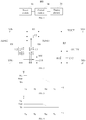

Classifications
-
- A—HUMAN NECESSITIES
- A24—TOBACCO; CIGARS; CIGARETTES; SIMULATED SMOKING DEVICES; SMOKERS' REQUISITES
- A24F—SMOKERS' REQUISITES; MATCH BOXES; SIMULATED SMOKING DEVICES
- A24F40/00—Electrically operated smoking devices; Component parts thereof; Manufacture thereof; Maintenance or testing thereof; Charging means specially adapted therefor
- A24F40/50—Control or monitoring
- A24F40/57—Temperature control
Definitions
- the present disclosure relates to electronic atomization technology, and in particular, to an electronic atomization device and a method for controlling a heating element of the electronic atomization device, and a storage medium.
- An electronic atomization device and a method for controlling a heating element of the electronic atomization device, and a storage medium are provided in some examples of the present disclosure.
- an electronic atomization device includes: a heating element, configured to heat an aerosol-generating substance; a power module, configured to supply power to the heating element; and a control module, connected between the power module and the heating element and configured to receive a startup instruction from a user and control the power module to supply power to the heating element according to the startup instruction.
- the control module is further configured to control the heating element to operate under a first parameter value in a first time period, control the heating element to operate under a second parameter value in a second time period, control the heating element to operate under a parameter value reducing from the second parameter value to a third parameter value in a third time period, and control the heating element to operate under the third parameter value in a fourth time period; wherein the second parameter value is less than the first parameter value.
- the first parameter value, the second parameter value, and the third parameter value are one of a power value, a voltage value, and a temperature value.
- the second parameter value is a preset output value acquired from the control module.
- the first parameter value and the third parameter value are acquired from the second parameter value.
- the first parameter value, the second parameter value, and the third parameter value are temperature values
- the control module is further configured to control a temperature of the heating element to increase from a room temperature to the first parameter value in the first time period.
- a ratio of the first parameter value to the second parameter value is greater than or equal to 1.1, and a ratio of the third parameter value to the second parameter value is less than or equal to 0.9.
- a duration of the first time period is greater than or equal to 5ms
- a duration of the second time period is greater than or equal to 100ms
- a duration of the third time period is greater than or equal to 10ms.
- a method for controlling a heating element of an electronic atomization device includes: controlling the heating element to operate under a first parameter value in a first time period; controlling the heating element to operate under a second parameter value in a second time period, and the second parameter value being less than the first parameter value; controlling the heating element to operate under a parameter value reducing from the second parameter value to a third parameter value in a third time period; and controlling the heating element to operate under the third parameter value in a fourth time period.
- the first parameter value, the second parameter value, and the third parameter value are one of a power value, a voltage value, and a temperature value
- the second parameter value is a preset output value
- the method further includes: acquiring the first parameter value and the third parameter value from the second parameter value.
- the first parameter value, the second parameter value, and the third parameter value are temperature values; the method further comprises: controlling a temperature of the heating element to increase from a room temperature to the first parameter value at a starting point of the first time period.
- the time for the heating element to increase from the room temperature to the first parameter value is less than 1 ms.
- the first time period, the second time period, the third time period, and the fourth time period are temporally continuous time periods.
- a ratio of the first parameter value to the second parameter value is greater than or equal to 1.1, and a ratio of the third parameter value to the second parameter value is less than or equal to 0.9.
- a duration of the first time period is greater than or equal to 5ms
- a duration of the second time period is greater than or equal to 100ms
- a duration of the third time period is greater than or equal to 10ms.
- a storage medium storing an instruction which, when executed by at least one processor, causes the at least one processor to perform the method as previously described.
- the heating element may operate under the first parameter value that is greater than the second parameter value in the first time period, and thus a heating efficiency of the heating element may be increased, and the temperature of the heating element may be rapidly increased.
- the heating element may further operate under the second parameter value which is medium-sized in the second time period, operate under a parameter value reducing from the second parameter value to the third parameter value in the third time period, and continuously operate under the third parameter value in the fourth time period. In this way, it is possible to reduce the possibility that the heating element has an excessively high temperature during the third and fourth time periods caused by the heat accumulation. Therefore, the aerosols generated by the electronic atomization device at various stages have consistent or uniform tastes, thereby improving the user experience of suction.
- FIG. 1 is a schematic structural view of an electronic atomization device according to some examples of the present disclosure.
- the electronic atomization device 100 may include a power module 10, a heating element 20, and a control module 30.
- the power module 10 may be connected to the heating element 20 and configured to supply power to the heating element 20.
- the control module 30 may be connected between the power module 10 and the heating element 20, that is, the control module 30 may be connected to both the power module 10 and the heating element 20.
- the control module 30 may be configured to receive a startup instruction from a user, and control the power module 10 to supply power to the heating element 20 according to the startup instruction.
- the heating element 20 may be configured to heat an aerosol-generating substance (such as tobacco or tobacco tar) received in the electronic atomization device 100. That is, in some examples, the power module 10 may be controlled by the control module 30 to supply power to the heating element 20, and the heating element 20 may operate under certain parameters and heat the aerosol-generating substance.
- an aerosol-generating substance such as tobacco or tobacco tar
- the power module 10 may be disposed inside the electronic atomization device 100. More specifically, the power module 10 may be implemented as a rechargeable battery or a battery pack. The power module 10 may also be an external power supply device connected to the electronic atomization device 100 through a power interface.
- the heating element 20 may be made of a temperature-controlled heating material, or may be made of a non-temperature-controlled heating material.
- the temperature-controlled heating material may be a material with a greater TCR (temperature coefficient of resistance) value, while the non-temperature-controlled heating material may be a material with a less TCR value.
- a resistance value of the heating element may be detected by using a system circuit.
- a temperature-measuring resistor may be connected in series in a load circuit of the heating element 20, and the temperature-measuring resistor R1 may be arranged near the heating element 20.
- the resistance value of the temperature-measuring resistor R1 may be acquired or calculated according to a voltage across the temperature-measuring resistor R1 and a current flows through the temperature-measuring resistor R1 detected by the system circuit.
- a temperature of the temperature-measuring resistor R1 (that is, the temperature of the heating element 20) may be acquired by looking up a correspondence or mapping relationship between the resistance value of the temperature-measuring resistor R1 and the temperature.
- the temperature may be further fed back to the control module 30, and the control module 30 may control an operating parameter of the heating element 20 according to the temperature of the heating element 20. In this way, when the heating element 20 heats the aerosol-generating substance, the aerosols generated at various stages have consistent or uniform tastes, thereby improving the user experience.
- the electronic atomization device 100 may further include a temperature control circuit capable of detecting both the TCR value of the temperature-controlled heating material and the TCR value of the non-temperature-controlled heating material.
- the temperature control circuit may be connected to the heating element 20 and the control module 30.
- FIG. 2 is a schematic structural diagram of a temperature control circuit according to some examples of the present disclosure.
- the temperature-measuring resistor R1 may be disposed near the heating element, and may be connected in series in the load circuit of the heating element 20.
- terminals VIN+ and VIN- may be respectively connected to output terminals of the power module, or may be connected to the output terminals of the power module through a voltage step-up/down circuit.
- Terminals VO+ and VO- may be respectively connected to the load circuit of the heating element. That is, the terminal VO+ may be an input terminal of the load circuit.
- the temperature-measuring resistor R1 may be connected between the terminals VIN+ and VIN-.
- a first differential operational amplifier U1 with a low amplification factor and a second differential operational amplifier U2 with a high amplification factor may be simultaneously utilized to sample or acquire the voltage across the temperature-measuring resistor R1.
- the first differential operational amplifier U1 may have a first amplification factor
- the second differential operational amplifier U2 may a second amplification factor
- the first amplification factor may be less than the second amplification factor. If the temperature-measuring resistor R1 is made of the temperature-controlled heating material, the resistance value of the temperature-measuring resistor R1 may be measured and acquired through the first differential operational amplifier U1 with a low amplification factor.
- the resistance value of the temperature-measuring resistor R1 may be measured by the second differential operational amplifier U2 with a high amplification factor. That is, no matter whether the temperature-measuring resistor R1 is made of the temperature-controlled heating material or the non-temperature-controlled heating material, the resistance value of the temperature-measuring resistor R1 may be measured and acquired through the temperature control circuit of the present disclosure.
- each of a non-inverting input terminal IN+ of the first differential operational amplifier U1 with a low amplification factor and a non-inverting input terminal IN+ of the second differential operational amplifier U2 with a high amplification factor may be connected to the terminal VIN+ and a first terminal of the temperature-measuring resistor R1.
- Each of an inverting input terminal IN- of the first differential operational amplifier U1 with a low amplification factor and an inverting input terminal IN- of the second differential operational amplifier U2 with a high amplification factor may be respectively connected to the input terminal VO+ of the load circuit and a second terminal of the temperature-measuring resistor R1.
- Each of a reference input terminal REF of the first differential operational amplifier U1 with a low amplification factor and a reference input terminal REF of the second differential operational amplifier U2 with a high amplification factor may be connected to the terminal VIN-.
- a sampling voltage across the temperature-measuring resistor R1 may be acquired by reading a value AD-R1 outputted after the sampling and amplification performed by the first differential operational amplifier U1 with a low amplification factor. If the heating element is made of the non-temperature-controlled heating material, the sampling voltage across the temperature-measuring resistor R1 may be acquired by reading an value AD-R2 outputted after the sampling and amplification performed by the second differential operational amplifier U2 with a high amplification factor.
- control module 30 may be configured to receive the sampling voltage across the temperature-measuring resistor R1 measured by the first differential operational amplifier U1 with a low amplification factor or the second differential operational amplifier U2 with a high amplification factor, and execute a method for controlling the heating element 20 of the electronic atomization device 20 provided in some examples of the present disclosure. That is, the control module 30 may be configured to control the output from the power module 10 to the heating element 20 according to the method for controlling the heating element 20, such that the heating element 20 may operate under a certain operating parameter. In this way, the aerosols generated by the electronic atomization device 100 after the atomization process may have consistent or uniform tastes during the suction, and the user experience may be improved.
- the control module 30 may be configured to control the heating element 20 to operate under a first parameter value in a first time period, control the heating element 20 to operate under a second parameter value in a second time period, control the heating element 20 to operate under a parameter value reducing from the second parameter value to a third parameter value in a third time period, and control the heating element 20 to operate under the third parameter value in a fourth time period.
- the second parameter value may be less than the first parameter value
- the third parameter value may be less than the second parameter value.
- the heating element 20 may operate under the first parameter value that is greater than the second parameter value in the first time period, and thus a heating efficiency of the heating element 20 may be increased, and the temperature of the heating element 20 may be rapidly increased.
- the heating element 20 may further operate under the second parameter value which is medium-sized in the second time period.
- medium-sized means that the second parameter value is less than the first parameter value and greater than the third parameter value.
- the heating element 20 may operate under a parameter value reducing from the second parameter value to the third parameter value, and the heating element 20 may continuously operate under the third parameter value in the fourth time period.
- the aerosols generated by the electronic atomization device 100 at various stages have consistent or uniform tastes, thereby improving the user experience of suction.
- the first parameter value, the second parameter value, and the third parameter value may be constant. That is, the heating element 20 may operate under the constant first parameter value in the first time period, operate under the constant second parameter value in the second time period, and operate under the constant third parameter value in the fourth time period. In the third time period, however, the heating element 20 may operate with a parameter value gradually decreasing from the second parameter value to the third parameter value. For example, the parameter value may be linearly decreased from the second parameter value to the third parameter value.
- the second parameter value may be a preset output value acquired from the control module 30.
- the preset output value may be a factory-set value. That is, a default value stored in the control module 30 before the electronic atomization device 100 is shipped from the factory.
- the preset output value may also be a value set by the user when using the electronic atomization device 100.
- the preset output value may be a value set by the user in the control module 30 when the user uses the electronic atomization device 100 for the first time.
- the preset output value may also be a value set by the user and included in the startup instruction received by the control module 30.
- the control module 30 may receive the startup instruction.
- the preset value may be utilized as the operative second parameter value
- the first parameter value and the third parameter value may be acquired according to / by utilizing the operative second parameter value
- the heating element 20 may operate under the first parameter value, the second parameter value, and the third parameter value.
- the electronic atomization device 100 may utilize the input value as the operative second parameter value, and the first parameter value and the third parameter value may be acquired according to the operative second parameter value.
- the heating element 20 may further operate under the first parameter value, the second parameter value, and the third parameter value.
- a ratio of the first parameter value to the second parameter value may be set to be greater than or equal to 1.1, and may be less than or equal to 2.
- the ratio of the first parameter value to the second parameter value may be 1.1, 1.15, 1.2, 1.3, 1.5, 2, and the like.
- a ratio of the third parameter value to the second parameter value may be set to be less than or equal to 0.9, and may be greater than or equal to 0.5.
- the ratio of the third parameter value to the second parameter value may be 0.9, 0.85, 0.8, 0.6, 0.5, and the like.
- the first parameter value and the third parameter value may be calculated or acquired from the second parameter value.
- the first time period, the second time period, the third time period, and the fourth time period may be temporally continuous time periods. That is, an ending point of the first time period is a starting point of the second time period, an ending point of the second time period is a starting point of the third time period, and an ending point of the third time period is a starting point of the fourth time period.
- a duration of the first time period may be greater than or equal to 5ms and may be less than or equal to 15ms.
- a duration of the second time period may be greater than or equal to 100ms and may be less than or equal to 300ms.
- a duration of the third time period may be greater than or equal to 10ms and may be less than or equal to 30ms.
- a duration of the fourth time period may be determined according to a specific time of the suction of the user. In some examples, as shown in FIGS. 3-5 , the duration of the first time period may be less than the duration of the second time period, and further less than the duration of the third time period.
- the heating element may operate under the first parameter value for at least 5ms, such as 5ms, 6ms, 7ms, 10ms, 15ms, and the like.
- the heating element may operate under the second parameter value for at least 100ms, such as 100ms, 110ms, 130ms, 180ms, 200ms, 300ms, and the like.
- the second parameter value may be reduced to the third parameter value, and the heating element 20 may operate for at least 10ms, such as 10ms, 12ms, 15ms, 20ms, 30ms, and the like.
- the first parameter value, the second parameter value, and the third parameter value may be selected from the group consisting of a power value, a voltage value, and a temperature value. That is, the control module 30 may control the operation of the heating element 20 by controlling one of an operating power, an operating voltage, and an operating temperature of the heating element 20.
- control module 30 may control the operating power of the heating element 20, such that the heating element 20 may operate at a first power value in the first time period, operate at a second power value less than the first power value in the second time period, operate at a power value decreasing from the second power value to a third power value, and operate at the third power value in the fourth time period.
- FIG. 3 is a graph illustrating a relationship between a power W of the heating element and the time T according to some examples of the present disclosure.
- the heating element 20 may firstly operate at a power Wa during a time period Ta.
- the power Wa may be reduced to a power Wset, and the heating element 20 may operate at the power Wset during a time period Tb.
- the power Wa may be greater than Wset, such that a heating rate of the heating element in the cooling state may be increased.
- the power Wset may be gradually reduced, and the power may be reduced to a power Wc at an ending point of the time period Tbc.
- the heating element 20 may continuously operate at the power Wc during the time period Tc until the end of the suction.
- the heating element 20 may continuously operate at the power Wc during the time period Tc until the end of the suction.
- FIG. 4 is a graph illustrating a relationship between a voltage V of the heating element 20 and the time T according to some examples of the present disclosure.
- the control module 30 may be configured to control the operating voltage of the heating element 20.
- the heating element 20 may firstly operate at a voltage Va during the time period Ta.
- the voltage Va may be reduced to a voltage Vset, and the heating element 20 may operate at the voltage Vset during the time period Tb.
- the voltage Va may be greater than Vset, such that a heating rate of the heating element in the cooling state may be increased.
- the voltage Vset may be gradually reduced, and the voltage may be reduced to a voltage Vc at an ending point of the time period Tbc.
- the heating element 20 may continuously operate at the voltage Vc during the time period Tc until the end of the suction.
- FIG. 5 is a graph illustrating a relationship between a temperature TEMP of the heating element 20 and the time T according to some examples of the present disclosure.
- the control module 30 may be configured to control the operating temperature of the heating element 20.
- the control module 30 may be configured to control the heating element 20 such that the temperature of the heating element 20 may be increased from a room temperature to a temperature TEMPa, and the heating element 20 may operate at the temperature TEMPa during most of the time period Ta.
- the temperature of the heating element 20 may be reduced from the temperature TEMPa to a temperature TEMPset, and the heating element 20 may operate at the temperature TEMPset during the time period Tb.
- the temperature TEMPa may be greater than the temperature TEMPset, such that a heating rate of the heating element in the cooling state may be increased.
- the temperature TEMPset may be gradually reduced, and the temperature may be reduced to a temperature TEMPc at an ending point of the time period Tbc.
- the heating element 20 may continuously operate at the temperature TEMPc during the time period Tc until the end of the suction.
- the time taken for increasing the temperature of the heating element from the room temperature to the temperature TEMPa may be controlled to be less than 1 ms, so as to shorten a preheating time of the heating element 20. In this way, the temperature of the heating element 20 may be rapidly increased to a normal heating temperature.
- FIG 6 is a flow chart of a method for controlling the heating element of the electronic atomization device according to some examples of the present disclosure.
- the electronic atomization device 100 may be the electronic atomization device 100 according to some examples afore-mentioned.
- the method for controlling the heating element provided in some examples of the present disclosure may be executed by the control module 30 mentioned in the above examples to control the operation of the heating element 20.
- the method may include operations executed by the following blocks.
- the heating element 20 may be controlled to operate under a first parameter value.
- the heating element 20 may be controlled to operate under a second parameter value, and the second parameter value may be less than the first parameter value.
- the second parameter value may be controlled to be reduced to a third parameter value. That is to say, the heating element 20 may operate at a temperature gradually decreasing from the second parameter value to the third parameter value. In some examples, the heating element 20 may operate at a temperature linearly decreasing from the second parameter value to the third parameter value.
- the heating element 20 may be controlled to operate under the third parameter value.
- the first parameter value, the second parameter value, and the third parameter value may be selected from the group consisting of a power value, a voltage value, and a temperature value. That is, it is possible to control the operation of the heating element 20 by controlling one of an operating power, an operating voltage, and an operating temperature of the heating element 20.
- the first time period, the second time period, the third time period, and the fourth time period may be temporally continuous time periods, such that the heating element 20 may continuously operate to generate aerosols.
- a duration of the first time period may be greater than or equal to 5ms
- a duration of the second time period may be greater than or equal to 100ms
- a duration of the third time period may be greater than or equal to 10ms.
- the block S10 may include: controlling a temperature of the heating element 20 to increase from the room temperature to the first parameter value, and controlling the heating element 20 to operate at the first parameter value.
- the heating element 20 At the starting point of the first time period, that is, before controlling the heating element 20 to operate at the first temperature, it is also necessary to control the temperature of the heating element 20 to increase from the room temperature to the first temperature, such that the heating element 20 may operate at the constant first temperature for most of the first time period.
- the time required for increasing the temperature of the heating element 20 from the room temperature to the first temperature may be controlled to be less than 1 ms, so as to shorten a preheating time of the heating element. In this way, the temperature of the heating element 20 may be rapidly increased to a normal heating temperature.
- the second parameter value may be a preset output value.
- the preset output value may be a factory-set value, or a value inputted in the electronic atomization device 100 by the user via an input module when the user is activating the electronic atomization device 100.
- the second parameter value may be flexibly adjusted according to the aerosol-generating substances of different types, such that the aerosols having better tastes may be generated from the tobacco or tobacco tar of different types.
- the method may further include: acquiring the first parameter value and the third parameter value from the second parameter value.
- a ratio of the first parameter value to the second parameter value may be set to be greater than or equal to 1.1, and may be less than or equal to 2.
- the ratio of the first parameter value to the second parameter value may be 1.1, 1.15, 1.2, 1.3, 1.5, 2, and the like.
- a ratio of the third parameter value to the second parameter value may be set to be less than or equal to 0.9, and may be greater than or equal to 0.5.
- the ratio of the third parameter value to the second parameter value may be 0.9, 0.85, 0.8, 0.6, 0.5, and the like.
- the first parameter value and the third parameter value may be calculated or acquired from the second parameter value.
- the electronic atomization device may include at least one processor and a storage medium communicating with the at least one processor.
- the storage medium may store an instruction executable by the at least one processor.
- the at least one processor may be caused to perform the method as described in the examples described above.
- a processor and a storage medium connected to the processor may be provided.
- the processor may be connected to the storage medium through a bus or other methods.
- the storage medium may be a non-volatile computer-readable storage medium, and may be used to store non-volatile software programs, non-volatile computer executable programs, and modules, such as program instructions corresponding to the method for controlling the heating element of the electronic atomization device in the foregoing examples of the present disclosure.
- the processor may run the non-volatile software programs, instructions, and modules stored in the storage medium, to perform various functional applications and data processing corresponding to the method for controlling the heating element of the electronic atomization device, that is, to implement the functions of the method for controlling the heating element of the electronic atomization device in the method examples as previously described.
Landscapes
- Control Of Resistance Heating (AREA)
- Disinfection, Sterilisation Or Deodorisation Of Air (AREA)
Abstract
Description
- The present disclosure relates to electronic atomization technology, and in particular, to an electronic atomization device and a method for controlling a heating element of the electronic atomization device, and a storage medium.
- With development of technologies and people's pursuits of healthy lives, electronic cigarettes are available in the market to bake or heat aerosol-generating substances, such as tobacco tar, tobacco rods, or tobacco products, to generate aerosols such as smoke.
- However, during the whole suction process, the tastes of the aerosols generated by heating and atomization are inconsistent, and the user experience may be affected.
- An electronic atomization device and a method for controlling a heating element of the electronic atomization device, and a storage medium are provided in some examples of the present disclosure.
- In some aspects, an electronic atomization device is provided. The electronic atomization device includes: a heating element, configured to heat an aerosol-generating substance; a power module, configured to supply power to the heating element; and a control module, connected between the power module and the heating element and configured to receive a startup instruction from a user and control the power module to supply power to the heating element according to the startup instruction. The control module is further configured to control the heating element to operate under a first parameter value in a first time period, control the heating element to operate under a second parameter value in a second time period, control the heating element to operate under a parameter value reducing from the second parameter value to a third parameter value in a third time period, and control the heating element to operate under the third parameter value in a fourth time period; wherein the second parameter value is less than the first parameter value.
- In some examples, the first parameter value, the second parameter value, and the third parameter value are one of a power value, a voltage value, and a temperature value. The second parameter value is a preset output value acquired from the control module.
- In some examples, the first parameter value and the third parameter value are acquired from the second parameter value.
- In some examples, the first parameter value, the second parameter value, and the third parameter value are temperature values, and the control module is further configured to control a temperature of the heating element to increase from a room temperature to the first parameter value in the first time period.
- In some examples, a ratio of the first parameter value to the second parameter value is greater than or equal to 1.1, and a ratio of the third parameter value to the second parameter value is less than or equal to 0.9.
- In some examples, a duration of the first time period is greater than or equal to 5ms, a duration of the second time period is greater than or equal to 100ms, and a duration of the third time period is greater than or equal to 10ms.
- In some aspects, a method for controlling a heating element of an electronic atomization device is provided. The method includes: controlling the heating element to operate under a first parameter value in a first time period; controlling the heating element to operate under a second parameter value in a second time period, and the second parameter value being less than the first parameter value; controlling the heating element to operate under a parameter value reducing from the second parameter value to a third parameter value in a third time period; and controlling the heating element to operate under the third parameter value in a fourth time period.
- In some examples, the first parameter value, the second parameter value, and the third parameter value are one of a power value, a voltage value, and a temperature value, and the second parameter value is a preset output value.
- In some examples, the method further includes: acquiring the first parameter value and the third parameter value from the second parameter value.
- In some examples, the first parameter value, the second parameter value, and the third parameter value are temperature values; the method further comprises: controlling a temperature of the heating element to increase from a room temperature to the first parameter value at a starting point of the first time period.
- In some examples, the time for the heating element to increase from the room temperature to the first parameter value is less than 1 ms.
- In some examples, the first time period, the second time period, the third time period, and the fourth time period are temporally continuous time periods.
- In some examples, a ratio of the first parameter value to the second parameter value is greater than or equal to 1.1, and a ratio of the third parameter value to the second parameter value is less than or equal to 0.9.
- In some examples, a duration of the first time period is greater than or equal to 5ms, a duration of the second time period is greater than or equal to 100ms, and a duration of the third time period is greater than or equal to 10ms.
- In some aspects, a storage medium is provided. The storage medium storing an instruction which, when executed by at least one processor, causes the at least one processor to perform the method as previously described.
- Some technical effects of some examples of the present disclosure may include the following: compared with the related art, in some examples of the present disclosure, the heating element may operate under the first parameter value that is greater than the second parameter value in the first time period, and thus a heating efficiency of the heating element may be increased, and the temperature of the heating element may be rapidly increased. The heating element may further operate under the second parameter value which is medium-sized in the second time period, operate under a parameter value reducing from the second parameter value to the third parameter value in the third time period, and continuously operate under the third parameter value in the fourth time period. In this way, it is possible to reduce the possibility that the heating element has an excessively high temperature during the third and fourth time periods caused by the heat accumulation. Therefore, the aerosols generated by the electronic atomization device at various stages have consistent or uniform tastes, thereby improving the user experience of suction.
- In order to describe the technical solutions in the embodiments of the present disclosure more clearly, the following briefly introduces the accompanying drawings required for describing the embodiments. Apparently, the accompanying drawings in the following description are merely some embodiments of the present disclosure; for those skilled in the art. Other drawings can be obtained based on these drawings without creative efforts.
-
FIG. 1 is a schematic structural view of an electronic atomization device according to some examples of the present disclosure. -
FIG. 2 is a schematic structural diagram of a temperature control circuit according to some examples of the present disclosure. -
FIG. 3 is a graph illustrating a relationship between a power of the heating element and time according to some examples of the present disclosure. -
FIG. 4 is a graph illustrating a relationship between a voltage of the heating element and the time according to some examples of the present disclosure. -
FIG. 5 is a graph illustrating a relationship between a temperature of the heating element and the time according to some examples of the present disclosure. -
FIG 6 is a flow chart of a method for controlling the heating element of the electronic atomization device according to some examples of the present disclosure. -
FIG. 7 is a schematic diagram of a hardware structure of the electronic atomization device according to some examples of the present disclosure. - The disclosure will now be described clearly and comprehensively with reference to the accompanying drawings and examples. Apparently, the described examples herein are only a part of the embodiments of the present disclosure, not all of the embodiments. All other examples obtained by those skilled in the art based on the examples of the present disclosure without creative efforts shall fall within the protection scope of the present invention.
-
FIG. 1 is a schematic structural view of an electronic atomization device according to some examples of the present disclosure. As shown inFIG. 1 , theelectronic atomization device 100 may include apower module 10, aheating element 20, and acontrol module 30. Thepower module 10 may be connected to theheating element 20 and configured to supply power to theheating element 20. Thecontrol module 30 may be connected between thepower module 10 and theheating element 20, that is, thecontrol module 30 may be connected to both thepower module 10 and theheating element 20. Thecontrol module 30 may be configured to receive a startup instruction from a user, and control thepower module 10 to supply power to theheating element 20 according to the startup instruction. Theheating element 20 may be configured to heat an aerosol-generating substance (such as tobacco or tobacco tar) received in theelectronic atomization device 100. That is, in some examples, thepower module 10 may be controlled by thecontrol module 30 to supply power to theheating element 20, and theheating element 20 may operate under certain parameters and heat the aerosol-generating substance. - The
power module 10 may be disposed inside theelectronic atomization device 100. More specifically, thepower module 10 may be implemented as a rechargeable battery or a battery pack. Thepower module 10 may also be an external power supply device connected to theelectronic atomization device 100 through a power interface. - The
heating element 20 may be made of a temperature-controlled heating material, or may be made of a non-temperature-controlled heating material. In some examples, the temperature-controlled heating material may be a material with a greater TCR (temperature coefficient of resistance) value, while the non-temperature-controlled heating material may be a material with a less TCR value. - When the
heating element 20 is made of the temperature-controlled heating material, since the temperature-controlled heating material has a greater TCR value, a resistance value of the heating element may be detected by using a system circuit. During the operation of theelectronic atomization device 100, a temperature-measuring resistor may be connected in series in a load circuit of theheating element 20, and the temperature-measuring resistor R1 may be arranged near theheating element 20. The resistance value of the temperature-measuring resistor R1 may be acquired or calculated according to a voltage across the temperature-measuring resistor R1 and a current flows through the temperature-measuring resistor R1 detected by the system circuit. A temperature of the temperature-measuring resistor R1 (that is, the temperature of the heating element 20) may be acquired by looking up a correspondence or mapping relationship between the resistance value of the temperature-measuring resistor R1 and the temperature. The temperature may be further fed back to thecontrol module 30, and thecontrol module 30 may control an operating parameter of theheating element 20 according to the temperature of theheating element 20. In this way, when theheating element 20 heats the aerosol-generating substance, the aerosols generated at various stages have consistent or uniform tastes, thereby improving the user experience. - When the
heating element 20 is made of the non-temperature-controlled heating material, since the non-temperature-controlled heating material has a less TCR value, the resistance value of the heating element cannot be detected by using the above-mentioned system circuit. Therefore, in some examples of the present disclosure, theelectronic atomization device 100 may further include a temperature control circuit capable of detecting both the TCR value of the temperature-controlled heating material and the TCR value of the non-temperature-controlled heating material. The temperature control circuit may be connected to theheating element 20 and thecontrol module 30. -
FIG. 2 is a schematic structural diagram of a temperature control circuit according to some examples of the present disclosure. As shown inFIG. 2 , in some examples, the temperature-measuring resistor R1 may be disposed near the heating element, and may be connected in series in the load circuit of theheating element 20. In some examples, terminals VIN+ and VIN- may be respectively connected to output terminals of the power module, or may be connected to the output terminals of the power module through a voltage step-up/down circuit. Terminals VO+ and VO- may be respectively connected to the load circuit of the heating element. That is, the terminal VO+ may be an input terminal of the load circuit. The temperature-measuring resistor R1 may be connected between the terminals VIN+ and VIN-. - In some examples, a first differential operational amplifier U1 with a low amplification factor and a second differential operational amplifier U2 with a high amplification factor may be simultaneously utilized to sample or acquire the voltage across the temperature-measuring resistor R1. Herein, the first differential operational amplifier U1 may have a first amplification factor, the second differential operational amplifier U2 may a second amplification factor, and the first amplification factor may be less than the second amplification factor. If the temperature-measuring resistor R1 is made of the temperature-controlled heating material, the resistance value of the temperature-measuring resistor R1 may be measured and acquired through the first differential operational amplifier U1 with a low amplification factor. If the temperature-measuring resistor R1 is made of the non-temperature-controlled heating material, the resistance value of the temperature-measuring resistor R1 may be measured by the second differential operational amplifier U2 with a high amplification factor. That is, no matter whether the temperature-measuring resistor R1 is made of the temperature-controlled heating material or the non-temperature-controlled heating material, the resistance value of the temperature-measuring resistor R1 may be measured and acquired through the temperature control circuit of the present disclosure.
- More specifically, as shown in
FIG. 2 , each of a non-inverting input terminal IN+ of the first differential operational amplifier U1 with a low amplification factor and a non-inverting input terminal IN+ of the second differential operational amplifier U2 with a high amplification factor may be connected to the terminal VIN+ and a first terminal of the temperature-measuring resistor R1. Each of an inverting input terminal IN- of the first differential operational amplifier U1 with a low amplification factor and an inverting input terminal IN- of the second differential operational amplifier U2 with a high amplification factor may be respectively connected to the input terminal VO+ of the load circuit and a second terminal of the temperature-measuring resistor R1. Each of a reference input terminal REF of the first differential operational amplifier U1 with a low amplification factor and a reference input terminal REF of the second differential operational amplifier U2 with a high amplification factor may be connected to the terminal VIN-. - During the operation of the electronic atomization device, if the heating element is made of the temperature-controlled heating material, a sampling voltage across the temperature-measuring resistor R1 may be acquired by reading a value AD-R1 outputted after the sampling and amplification performed by the first differential operational amplifier U1 with a low amplification factor. If the heating element is made of the non-temperature-controlled heating material, the sampling voltage across the temperature-measuring resistor R1 may be acquired by reading an value AD-R2 outputted after the sampling and amplification performed by the second differential operational amplifier U2 with a high amplification factor.
- In some examples, the
control module 30 may be configured to receive the sampling voltage across the temperature-measuring resistor R1 measured by the first differential operational amplifier U1 with a low amplification factor or the second differential operational amplifier U2 with a high amplification factor, and execute a method for controlling theheating element 20 of theelectronic atomization device 20 provided in some examples of the present disclosure. That is, thecontrol module 30 may be configured to control the output from thepower module 10 to theheating element 20 according to the method for controlling theheating element 20, such that theheating element 20 may operate under a certain operating parameter. In this way, the aerosols generated by theelectronic atomization device 100 after the atomization process may have consistent or uniform tastes during the suction, and the user experience may be improved. - More specifically, after the connections among the
power module 10, theheating element 20, and thecontrol module 30 are completed, thecontrol module 30 may be configured to control theheating element 20 to operate under a first parameter value in a first time period, control theheating element 20 to operate under a second parameter value in a second time period, control theheating element 20 to operate under a parameter value reducing from the second parameter value to a third parameter value in a third time period, and control theheating element 20 to operate under the third parameter value in a fourth time period. In some examples, the second parameter value may be less than the first parameter value, and the third parameter value may be less than the second parameter value. - In summary, in some examples, the
heating element 20 may operate under the first parameter value that is greater than the second parameter value in the first time period, and thus a heating efficiency of theheating element 20 may be increased, and the temperature of theheating element 20 may be rapidly increased. Theheating element 20 may further operate under the second parameter value which is medium-sized in the second time period. Herein, "medium-sized" means that the second parameter value is less than the first parameter value and greater than the third parameter value. In the third time period, theheating element 20 may operate under a parameter value reducing from the second parameter value to the third parameter value, and theheating element 20 may continuously operate under the third parameter value in the fourth time period. In this way, it is possible to reduce the possibility that theheating element 20 has an excessively high temperature during the third and fourth time periods caused by the heat accumulation. Therefore, the aerosols generated by theelectronic atomization device 100 at various stages have consistent or uniform tastes, thereby improving the user experience of suction. - In some examples, the first parameter value, the second parameter value, and the third parameter value may be constant. That is, the
heating element 20 may operate under the constant first parameter value in the first time period, operate under the constant second parameter value in the second time period, and operate under the constant third parameter value in the fourth time period. In the third time period, however, theheating element 20 may operate with a parameter value gradually decreasing from the second parameter value to the third parameter value. For example, the parameter value may be linearly decreased from the second parameter value to the third parameter value. - In some examples, the second parameter value may be a preset output value acquired from the
control module 30. In some examples, the preset output value may be a factory-set value. That is, a default value stored in thecontrol module 30 before theelectronic atomization device 100 is shipped from the factory. - In some examples, the preset output value may also be a value set by the user when using the
electronic atomization device 100. For example, the preset output value may be a value set by the user in thecontrol module 30 when the user uses theelectronic atomization device 100 for the first time. In some examples, the preset output value may also be a value set by the user and included in the startup instruction received by thecontrol module 30. - During the operation of the
electronic atomization device 100, thecontrol module 30 may receive the startup instruction. When a preset value of the second parameter value is stored in theelectronic atomization device 100, the preset value may be utilized as the operative second parameter value, the first parameter value and the third parameter value may be acquired according to / by utilizing the operative second parameter value, and theheating element 20 may operate under the first parameter value, the second parameter value, and the third parameter value. - When the startup instruction includes an input value set for the second parameter value, the
electronic atomization device 100 may utilize the input value as the operative second parameter value, and the first parameter value and the third parameter value may be acquired according to the operative second parameter value. Theheating element 20 may further operate under the first parameter value, the second parameter value, and the third parameter value. - In some examples, a ratio of the first parameter value to the second parameter value may be set to be greater than or equal to 1.1, and may be less than or equal to 2. For example, the ratio of the first parameter value to the second parameter value may be 1.1, 1.15, 1.2, 1.3, 1.5, 2, and the like. In some examples, a ratio of the third parameter value to the second parameter value may be set to be less than or equal to 0.9, and may be greater than or equal to 0.5. For example, the ratio of the third parameter value to the second parameter value may be 0.9, 0.85, 0.8, 0.6, 0.5, and the like. Thus, the first parameter value and the third parameter value may be calculated or acquired from the second parameter value.
- In some examples, the first time period, the second time period, the third time period, and the fourth time period may be temporally continuous time periods. That is, an ending point of the first time period is a starting point of the second time period, an ending point of the second time period is a starting point of the third time period, and an ending point of the third time period is a starting point of the fourth time period.
- In some examples, a duration of the first time period may be greater than or equal to 5ms and may be less than or equal to 15ms. A duration of the second time period may be greater than or equal to 100ms and may be less than or equal to 300ms. A duration of the third time period may be greater than or equal to 10ms and may be less than or equal to 30ms. A duration of the fourth time period may be determined according to a specific time of the suction of the user. In some examples, as shown in
FIGS. 3-5 , the duration of the first time period may be less than the duration of the second time period, and further less than the duration of the third time period. - More specifically, in the first time period, the heating element may operate under the first parameter value for at least 5ms, such as 5ms, 6ms, 7ms, 10ms, 15ms, and the like. In the second time period, the heating element may operate under the second parameter value for at least 100ms, such as 100ms, 110ms, 130ms, 180ms, 200ms, 300ms, and the like. In the third period, the second parameter value may be reduced to the third parameter value, and the
heating element 20 may operate for at least 10ms, such as 10ms, 12ms, 15ms, 20ms, 30ms, and the like. - The first parameter value, the second parameter value, and the third parameter value may be selected from the group consisting of a power value, a voltage value, and a temperature value. That is, the
control module 30 may control the operation of theheating element 20 by controlling one of an operating power, an operating voltage, and an operating temperature of theheating element 20. - For example, in some example, the
control module 30 may control the operating power of theheating element 20, such that theheating element 20 may operate at a first power value in the first time period, operate at a second power value less than the first power value in the second time period, operate at a power value decreasing from the second power value to a third power value, and operate at the third power value in the fourth time period. -
FIG. 3 is a graph illustrating a relationship between a power W of the heating element and the time T according to some examples of the present disclosure. In some examples, more specifically, as shown inFIG. 3 , theheating element 20 may firstly operate at a power Wa during a time period Ta. At the ending point of the time period Ta, the power Wa may be reduced to a power Wset, and theheating element 20 may operate at the power Wset during a time period Tb. Herein, the power Wa may be greater than Wset, such that a heating rate of the heating element in the cooling state may be increased. At a starting point of a time period Tbc, the power Wset may be gradually reduced, and the power may be reduced to a power Wc at an ending point of the time period Tbc. After that, theheating element 20 may continuously operate at the power Wc during the time period Tc until the end of the suction. Thus, it is possible to reduce the possibility that theheating element 20 has an excessively high temperature during the periods Tbc and Tc due to the heat accumulating performance of theheating element 20. -
FIG. 4 is a graph illustrating a relationship between a voltage V of theheating element 20 and the time T according to some examples of the present disclosure. Thecontrol module 30 may be configured to control the operating voltage of theheating element 20. In some examples, as shown inFIG. 4 , theheating element 20 may firstly operate at a voltage Va during the time period Ta. At the ending point of the time period Ta, the voltage Va may be reduced to a voltage Vset, and theheating element 20 may operate at the voltage Vset during the time period Tb. Herein, the voltage Va may be greater than Vset, such that a heating rate of the heating element in the cooling state may be increased. At a starting point of a time period Tbc, the voltage Vset may be gradually reduced, and the voltage may be reduced to a voltage Vc at an ending point of the time period Tbc. After that, theheating element 20 may continuously operate at the voltage Vc during the time period Tc until the end of the suction. Thus, it is possible to reduce the possibility that theheating element 20 has an excessively high temperature during the periods Tbc and Tc due to the heat accumulating performance of theheating element 20. -
FIG. 5 is a graph illustrating a relationship between a temperature TEMP of theheating element 20 and the time T according to some examples of the present disclosure. Thecontrol module 30 may be configured to control the operating temperature of theheating element 20. In some examples, as shown inFIG. 5 , at the starting point of the time period Ta, thecontrol module 30 may be configured to control theheating element 20 such that the temperature of theheating element 20 may be increased from a room temperature to a temperature TEMPa, and theheating element 20 may operate at the temperature TEMPa during most of the time period Ta. At the ending point of the Ta period, the temperature of theheating element 20 may be reduced from the temperature TEMPa to a temperature TEMPset, and theheating element 20 may operate at the temperature TEMPset during the time period Tb. Herein, the temperature TEMPa may be greater than the temperature TEMPset, such that a heating rate of the heating element in the cooling state may be increased. At a starting point of the time period Tbc, the temperature TEMPset may be gradually reduced, and the temperature may be reduced to a temperature TEMPc at an ending point of the time period Tbc. After that, theheating element 20 may continuously operate at the temperature TEMPc during the time period Tc until the end of the suction. Thus, it is possible to reduce the possibility that theheating element 20 has an excessively high temperature during the periods Tbc and Tc due to the heat accumulating performance of theheating element 20. - In some examples, the time taken for increasing the temperature of the heating element from the room temperature to the temperature TEMPa may be controlled to be less than 1 ms, so as to shorten a preheating time of the
heating element 20. In this way, the temperature of theheating element 20 may be rapidly increased to a normal heating temperature. -
FIG 6 is a flow chart of a method for controlling the heating element of the electronic atomization device according to some examples of the present disclosure. Theelectronic atomization device 100 may be theelectronic atomization device 100 according to some examples afore-mentioned. The method for controlling the heating element provided in some examples of the present disclosure may be executed by thecontrol module 30 mentioned in the above examples to control the operation of theheating element 20. The method may include operations executed by the following blocks. - At block S10, in a first time period, the
heating element 20 may be controlled to operate under a first parameter value. - At block S20, in a second time period, the
heating element 20 may be controlled to operate under a second parameter value, and the second parameter value may be less than the first parameter value. - At block S30, in a third time period, the second parameter value may be controlled to be reduced to a third parameter value. That is to say, the
heating element 20 may operate at a temperature gradually decreasing from the second parameter value to the third parameter value. In some examples, theheating element 20 may operate at a temperature linearly decreasing from the second parameter value to the third parameter value. - At block S40, in a fourth time period, the
heating element 20 may be controlled to operate under the third parameter value. - The first parameter value, the second parameter value, and the third parameter value may be selected from the group consisting of a power value, a voltage value, and a temperature value. That is, it is possible to control the operation of the
heating element 20 by controlling one of an operating power, an operating voltage, and an operating temperature of theheating element 20. - In some examples, the first time period, the second time period, the third time period, and the fourth time period may be temporally continuous time periods, such that the
heating element 20 may continuously operate to generate aerosols. - In some examples, a duration of the first time period may be greater than or equal to 5ms, a duration of the second time period may be greater than or equal to 100ms, and a duration of the third time period may be greater than or equal to 10ms.
- When the operation of the
heating element 20 is controlled by controlling the operating temperature of theheating element 20, the block S10 may include: controlling a temperature of theheating element 20 to increase from the room temperature to the first parameter value, and controlling theheating element 20 to operate at the first parameter value. - More specifically, at the starting point of the first time period, that is, before controlling the
heating element 20 to operate at the first temperature, it is also necessary to control the temperature of theheating element 20 to increase from the room temperature to the first temperature, such that theheating element 20 may operate at the constant first temperature for most of the first time period. - In some examples, the time required for increasing the temperature of the
heating element 20 from the room temperature to the first temperature may be controlled to be less than 1 ms, so as to shorten a preheating time of the heating element. In this way, the temperature of theheating element 20 may be rapidly increased to a normal heating temperature. - In some examples, the second parameter value may be a preset output value. For example, the preset output value may be a factory-set value, or a value inputted in the
electronic atomization device 100 by the user via an input module when the user is activating theelectronic atomization device 100. When the second parameter value is set by the user, the second parameter value may be flexibly adjusted according to the aerosol-generating substances of different types, such that the aerosols having better tastes may be generated from the tobacco or tobacco tar of different types. The method may further include: acquiring the first parameter value and the third parameter value from the second parameter value. - Further, a ratio of the first parameter value to the second parameter value may be set to be greater than or equal to 1.1, and may be less than or equal to 2. For example, the ratio of the first parameter value to the second parameter value may be 1.1, 1.15, 1.2, 1.3, 1.5, 2, and the like. In some examples, a ratio of the third parameter value to the second parameter value may be set to be less than or equal to 0.9, and may be greater than or equal to 0.5. For example, the ratio of the third parameter value to the second parameter value may be 0.9, 0.85, 0.8, 0.6, 0.5, and the like. Thus, the first parameter value and the third parameter value may be calculated or acquired from the second parameter value.
- An electronic atomization device may also be provided in some examples of the present disclosure. The electronic atomization device may include at least one processor and a storage medium communicating with the at least one processor. The storage medium may store an instruction executable by the at least one processor. When the instruction is executed by the at least one processor, the at least one processor may be caused to perform the method as described in the examples described above.
- As shown in
FIG. 7 , in some examples, a processor and a storage medium connected to the processor may be provided. The processor may be connected to the storage medium through a bus or other methods. - The storage medium may be a non-volatile computer-readable storage medium, and may be used to store non-volatile software programs, non-volatile computer executable programs, and modules, such as program instructions corresponding to the method for controlling the heating element of the electronic atomization device in the foregoing examples of the present disclosure. The processor may run the non-volatile software programs, instructions, and modules stored in the storage medium, to perform various functional applications and data processing corresponding to the method for controlling the heating element of the electronic atomization device, that is, to implement the functions of the method for controlling the heating element of the electronic atomization device in the method examples as previously described.
Claims (15)
- An electronic atomization device, characterized by comprising:a heating element (20), configured to heat an aerosol-generating substance;a power module (10), configured to supply power to the heating element (20); anda control module (30), connected between the power module (10) and the heating element (20) and configured to receive a startup instruction from a user and control the power module (10) to supply power to the heating element (20) according to the startup instruction;wherein the control module (30) is further configured to control the heating element (20) to operate under a first parameter value (Wa, Va, TEMPa) in a first time period (Ta), control the heating element (20) to operate under a second parameter value (Wset, Vset, TEMPset) in a second time period (Tb), control the heating element (20) to operate under a parameter value reducing from the second parameter value (Wset, Vset, TEMPset) to a third parameter value (Wc, Vc, TEMPc) in a third time period (Tbc), and control the heating element (20) to operate under the third parameter value (Wc, Vc, TEMPc) in a fourth time period (Tc); wherein the second parameter value (Wset, Vset, TEMPset) is less than the first parameter value (Wa, Va, TEMPa).
- The electronic atomization device according to claim 1, wherein the first parameter value (Wa, Va, TEMPa), the second parameter value (Wset, Vset, TEMPset), and the third parameter value (Wc, Vc, TEMPc) are one of a power value, a voltage value, and a temperature value;
the second parameter value (Wset, Vset, TEMPset) is a preset output value acquired from the control module (30). - The electronic atomization device according to claim 2, wherein the first parameter value (Wa, Va, TEMPa) and the third parameter value (Wc, Vc, TEMPc) are acquired from the second parameter value (Wset, Vset, TEMPset).
- The electronic atomization device according to any one of claims 1-3, wherein the first parameter value (Wa, Va, TEMPa), the second parameter value (Wset, Vset, TEMPset), and the third parameter value (Wc, Vc, TEMPc) are temperature values, and the control module (30) is further configured to control a temperature of the heating element (20) to increase from a room temperature to the first parameter value (Wa, Va, TEMPa) in the first time period (Ta).
- The electronic atomization device according to any one of claims 1-4, wherein a ratio of the first parameter value (Wa, Va, TEMPa) to the second parameter value (Wset, Vset, TEMPset) is greater than or equal to 1.1, and a ratio of the third parameter value (Wc, Vc, TEMPc) to the second parameter value (Wset, Vset, TEMPset) is less than or equal to 0.9.
- The electronic atomization device according to any one of claims 1-4, wherein a duration of the first time period (Ta) is greater than or equal to 5ms, a duration of the second time period (Tb) is greater than or equal to 100ms, and a duration of the third time period (Tbc) is greater than or equal to 10ms.
- A method for controlling a heating element (20) of an electronic atomization device, characterized in that, the method comprises:controlling the heating element (20) to operate under a first parameter value (Wa, Va, TEMPa) in a first time period (Ta);controlling the heating element (20) to operate under a second parameter value (Wset, Vset, TEMPset) in a second time period (Tb), and the second parameter value (Wset, Vset, TEMPset) being less than the first parameter value (Wa, Va, TEMPa);controlling the heating element (20) to operate under a parameter value reducing from the second parameter value (Wset, Vset, TEMPset) to a third parameter value (Wc, Vc, TEMPc) in a third time period (Tbc); andcontrolling the heating element (20) to operate under the third parameter value (Wc, Vc, TEMPc) in a fourth time period (Tc).
- The method according to claim 7, wherein the first parameter value (Wa, Va, TEMPa), the second parameter value (Wset, Vset, TEMPset), and the third parameter value (Wc, Vc, TEMPc) are one of a power value, a voltage value, and a temperature value, and the second parameter value (Wset, Vset, TEMPset) is a preset output value.
- The method according to claim 8, further comprising:
acquiring the first parameter value (Wa, Va, TEMPa) and the third parameter value (Wc, Vc, TEMPc) from the second parameter value (Wset, Vset, TEMPset). - The method according to any one of claims 7-9, wherein the first parameter value (Wa, Va, TEMPa), the second parameter value (Wset, Vset, TEMPset), and the third parameter value (Wc, Vc, TEMPc) are temperature values; the method further comprises: controlling a temperature of the heating element (20) to increase from a room temperature to the first parameter value (Wa, Va, TEMPa) at a starting point of the first time period (Ta).
- The method according to claim 10, wherein the time for the heating element (20) to increase from the room temperature to the first parameter value (Wa, Va, TEMPa) is less than 1 ms.
- The method according to any one of claims 7-11, wherein the first time period (Ta), the second time period (Tb), the third time period (Tbc), and the fourth time period (Tc) are temporally continuous time periods.
- The method according to any one of claims 7-12, wherein a ratio of the first parameter value (Wa, Va, TEMPa) to the second parameter value (Wset, Vset, TEMPset) is greater than or equal to 1.1, and a ratio of the third parameter value (Wc, Vc, TEMPc) to the second parameter value (Wset, Vset, TEMPset) is less than or equal to 0.9.
- The method according to any one of claims 7-12, wherein a duration of the first time period (Ta) is greater than or equal to 5ms, a duration of the second time period (Tb) is greater than or equal to 100ms, and a duration of the third time period (Tbc) is greater than or equal to 10ms.
- A storage medium storing an instruction which, when executed by at least one processor, causes the at least one processor to perform the method of any one of claims 7-14.
Applications Claiming Priority (1)
| Application Number | Priority Date | Filing Date | Title |
|---|---|---|---|
| CN201910054025.2A CN109730360A (en) | 2019-01-21 | 2019-01-21 | The control method of electronic atomization device and its heating element |
Publications (1)
| Publication Number | Publication Date |
|---|---|
| EP3682750A1 true EP3682750A1 (en) | 2020-07-22 |
Family
ID=66365440
Family Applications (1)
| Application Number | Title | Priority Date | Filing Date |
|---|---|---|---|
| EP20151384.3A Pending EP3682750A1 (en) | 2019-01-21 | 2020-01-13 | Electronic atomization device, method for controlling heating element of electronic atomization device, and storage medium |
Country Status (2)
| Country | Link |
|---|---|
| EP (1) | EP3682750A1 (en) |
| CN (1) | CN109730360A (en) |
Cited By (3)
| Publication number | Priority date | Publication date | Assignee | Title |
|---|---|---|---|---|
| WO2021224626A1 (en) * | 2020-05-07 | 2021-11-11 | Nicoventures Trading Limited | Non-combustible aerosol provision system |
| CN113907423A (en) * | 2021-08-31 | 2022-01-11 | 深圳麦时科技有限公司 | A heating assembly, an electronic atomization device and a control method for the heating assembly |
| US12520880B2 (en) | 2021-01-18 | 2026-01-13 | Altria Client Services Llc | Heat-not-burn (HNB) aerosol-generating devices including energy based heater control, and methods of controlling a heater |
Families Citing this family (27)
| Publication number | Priority date | Publication date | Assignee | Title |
|---|---|---|---|---|
| CN211910539U (en) * | 2019-05-16 | 2020-11-13 | 厦门蜂涛陶瓷有限公司 | Non-contact electronic cigarette heater and smoking article carrying assembly thereof |
| JP6678936B1 (en) | 2019-05-31 | 2020-04-15 | 日本たばこ産業株式会社 | Control device for aerosol aspirator and aerosol aspirator |
| JP6613008B1 (en) * | 2019-05-31 | 2019-11-27 | 日本たばこ産業株式会社 | Control device for aerosol inhaler and aerosol inhaler |
| CN110432543A (en) * | 2019-06-19 | 2019-11-12 | 深圳市精渡科技有限公司 | Setting, control method, electronic equipment and the storage medium of electronic cigarette and its parameter |
| CN110226776A (en) * | 2019-06-19 | 2019-09-13 | 深圳市精渡科技有限公司 | Electronic cigarette and its temperature control method, device and computer readable storage medium |
| CN110547511B (en) * | 2019-08-01 | 2022-10-11 | 深圳葭南科技有限公司 | Electronic cigarette control method for better restoring tobacco tar taste and electronic cigarette |
| CN110771960A (en) * | 2019-09-12 | 2020-02-11 | 深圳麦时科技有限公司 | Electronic smoking set, heating method thereof and computer storage medium |
| CN112841752B (en) * | 2019-11-12 | 2023-08-22 | 上海合元深蓝科技有限公司 | Aerosol generating device and control method thereof |
| CN114794564B (en) * | 2021-01-18 | 2025-09-02 | 深圳市新宜康科技股份有限公司 | Power supply circuit driving method and electronic heating device thereof |
| WO2022012424A1 (en) * | 2020-07-13 | 2022-01-20 | 深圳市新宜康科技股份有限公司 | Electric heating apparatus and power supply control method therefor |
| CN115413226B (en) * | 2020-03-05 | 2026-03-24 | 日本烟草国际股份有限公司 | Aerosol generators that provide an enhanced inhalation experience |
| WO2021196128A1 (en) * | 2020-04-02 | 2021-10-07 | 深圳麦时科技有限公司 | Heated aerosol generation device and method |
| CN112369707B (en) * | 2020-04-19 | 2022-07-19 | 湖北中烟工业有限责任公司 | Appliance for heating tobacco without burning and power supply control method |
| CN111920108B (en) * | 2020-09-07 | 2023-11-14 | 歌尔微电子股份有限公司 | Temperature control method and device, electronic cigarette and readable storage medium |
| CN112369674A (en) * | 2020-09-16 | 2021-02-19 | 湖北中烟工业有限责任公司 | Heating control method for aerosol-generating device and aerosol-generating device |
| CN112403405B (en) * | 2020-10-15 | 2023-01-03 | 深圳麦克韦尔科技有限公司 | Aerosol generating device, aerosol generating method, control circuit and storage medium |
| CN112385902B (en) * | 2020-11-03 | 2024-09-06 | 深圳市合元科技有限公司 | An aerosol generating device |
| CN112931983A (en) * | 2021-01-27 | 2021-06-11 | 深圳麦克韦尔科技有限公司 | Control method for atomizer and atomizer |
| CN113142684A (en) * | 2021-04-13 | 2021-07-23 | 深圳麦克韦尔科技有限公司 | Heating control method and electronic atomization device |
| CN113397226A (en) * | 2021-06-23 | 2021-09-17 | 四川三联新材料有限公司 | Heating cigarette atomizing device and method for keeping consistent taste |
| CN113907422B (en) * | 2021-08-31 | 2024-07-05 | 深圳麦时科技有限公司 | Heating assembly, electronic atomizing device and control method of heating assembly |
| CN114128929B (en) * | 2021-11-18 | 2024-05-14 | 深圳市华诚达精密工业有限公司 | Atomizing device power control method and device and electronic equipment |
| CN114532597B (en) * | 2022-01-27 | 2025-02-14 | 深圳市吉迩技术有限公司 | A sine wave based atomization output method and related equipment |
| CN115060731B (en) * | 2022-08-04 | 2022-12-02 | 楚能新能源股份有限公司 | Method for detecting scratch and metal exposure of negative membrane particles by variance algorithm |
| WO2026040847A1 (en) * | 2024-08-23 | 2026-02-26 | 思摩尔国际控股有限公司 | Control method and electronic atomization device |
| WO2026040848A1 (en) * | 2024-08-23 | 2026-02-26 | 思摩尔国际控股有限公司 | Control method and electronic atomization apparatus |
| WO2026040942A1 (en) * | 2024-08-23 | 2026-02-26 | 思摩尔国际控股有限公司 | Control method and electronic atomization apparatus |
Citations (5)
| Publication number | Priority date | Publication date | Assignee | Title |
|---|---|---|---|---|
| WO2014040988A2 (en) * | 2012-09-11 | 2014-03-20 | Philip Morris Products S.A. | Device and method for controlling an electrical heater to limit temperature |
| WO2014054035A1 (en) * | 2012-10-05 | 2014-04-10 | Smart Chip Microelectronic Co. Limited | Electronic smoke apparatus |
| CN108618207A (en) * | 2018-05-31 | 2018-10-09 | 绿烟实业(深圳)有限公司 | Control the method and inhalator generator that aerosol generates in inhalator generator |
| CN108652089A (en) * | 2018-08-07 | 2018-10-16 | 深圳市合元科技有限公司 | A kind of electronic cigarette control method and electronic smoking set |
| WO2018198153A1 (en) * | 2017-04-24 | 2018-11-01 | 日本たばこ産業株式会社 | Aerosol generation apparatus, method for controlling aerosol generation apparatus, and program |
Family Cites Families (11)
| Publication number | Priority date | Publication date | Assignee | Title |
|---|---|---|---|---|
| CN104026742A (en) * | 2013-03-05 | 2014-09-10 | 向智勇 | Heating control method and device for electronic cigarette |
| US9423152B2 (en) * | 2013-03-15 | 2016-08-23 | R. J. Reynolds Tobacco Company | Heating control arrangement for an electronic smoking article and associated system and method |
| CN106413444A (en) * | 2015-03-18 | 2017-02-15 | 惠州市吉瑞科技有限公司 | Method for heating heating wire of electronic cigarette vaporizer and electronic cigarette |
| CN107156915A (en) * | 2017-06-26 | 2017-09-15 | 常州市派腾电子技术服务有限公司 | A kind of pre-heating mean of electronic cigarette and electronic cigarette |
| CN107373759A (en) * | 2017-07-21 | 2017-11-24 | 深圳市新宜康电子技术有限公司 | The startup method that electronic smoke atomizer quickly heats |
| CN107296301A (en) * | 2017-08-18 | 2017-10-27 | 深圳市卓力能电子有限公司 | A kind of power for heating non-burning electronic cigarette and temperature Time-sharing control method and smoking set |
| CN108158045A (en) * | 2018-03-13 | 2018-06-15 | 卓尔悦欧洲控股有限公司 | The control method and device of electronic cigarette |
| CN109002066B (en) * | 2018-04-13 | 2020-02-28 | 赫斯提亚深圳生物科技有限公司 | Electronic cigarette and temperature detection control method thereof |
| CN108783599A (en) * | 2018-06-15 | 2018-11-13 | 芜湖启迪睿视信息技术有限公司 | A kind of application method of the customized non-burning smoking apparatus of heating process |
| CN108783602A (en) * | 2018-06-27 | 2018-11-13 | 威滔电子科技(深圳)有限公司 | Control the method and device that aerosol generating device generates aerosol |
| CN109222249A (en) * | 2018-10-18 | 2019-01-18 | 厦门盈趣科技股份有限公司 | A kind of electronic cigarette method for heating and controlling and electronic cigarette |
-
2019
- 2019-01-21 CN CN201910054025.2A patent/CN109730360A/en active Pending
-
2020
- 2020-01-13 EP EP20151384.3A patent/EP3682750A1/en active Pending
Patent Citations (5)
| Publication number | Priority date | Publication date | Assignee | Title |
|---|---|---|---|---|
| WO2014040988A2 (en) * | 2012-09-11 | 2014-03-20 | Philip Morris Products S.A. | Device and method for controlling an electrical heater to limit temperature |
| WO2014054035A1 (en) * | 2012-10-05 | 2014-04-10 | Smart Chip Microelectronic Co. Limited | Electronic smoke apparatus |
| WO2018198153A1 (en) * | 2017-04-24 | 2018-11-01 | 日本たばこ産業株式会社 | Aerosol generation apparatus, method for controlling aerosol generation apparatus, and program |
| CN108618207A (en) * | 2018-05-31 | 2018-10-09 | 绿烟实业(深圳)有限公司 | Control the method and inhalator generator that aerosol generates in inhalator generator |
| CN108652089A (en) * | 2018-08-07 | 2018-10-16 | 深圳市合元科技有限公司 | A kind of electronic cigarette control method and electronic smoking set |
Cited By (4)
| Publication number | Priority date | Publication date | Assignee | Title |
|---|---|---|---|---|
| WO2021224626A1 (en) * | 2020-05-07 | 2021-11-11 | Nicoventures Trading Limited | Non-combustible aerosol provision system |
| US12520880B2 (en) | 2021-01-18 | 2026-01-13 | Altria Client Services Llc | Heat-not-burn (HNB) aerosol-generating devices including energy based heater control, and methods of controlling a heater |
| CN113907423A (en) * | 2021-08-31 | 2022-01-11 | 深圳麦时科技有限公司 | A heating assembly, an electronic atomization device and a control method for the heating assembly |
| CN113907423B (en) * | 2021-08-31 | 2023-10-20 | 深圳麦时科技有限公司 | Heating assembly, electronic atomizing device and control method of heating assembly |
Also Published As
| Publication number | Publication date |
|---|---|
| CN109730360A (en) | 2019-05-10 |
Similar Documents
| Publication | Publication Date | Title |
|---|---|---|
| CN109730360A (en) | The control method of electronic atomization device and its heating element | |
| US11454996B2 (en) | Electronic cigarette temperature control system and method, and electronic cigarette with the same | |
| CN114376274B (en) | Aerosol generating device and control method, control device and storage medium thereof | |
| EP4458192A1 (en) | Aerosol generation apparatus, control method and control apparatus therefor, and storage medium | |
| EP3051280A1 (en) | Metal oxide based gas sensor with pulsed heating | |
| WO2016101200A1 (en) | Dynamic output power management for electronic smoking device | |
| CN109247621B (en) | Heating temperature control method and device based on electronic cigarette and electronic cigarette equipment | |
| CN105849517B (en) | Digital temperature sensor with integrated timer and burst mode | |
| JP2022545964A (en) | Electronic cigarette device, heating method thereof, and computer storage medium | |
| KR20200005082A (en) | Method and apparatus for generating aerosols | |
| US20210195960A1 (en) | Control circuit and electronic cigarette | |
| EP4710787A1 (en) | Control method for aerosol generation apparatus, and aerosol generation apparatus | |
| CN115054002B (en) | Atomizing equipment heating control method, device, circuit, medium, program product | |
| EP4643686A1 (en) | Aerosol generation system and heating control method therefor | |
| CN114223969A (en) | Temperature control method and device for heating non-combustible electronic cigarette, electronic cigarette and medium | |
| JP5964678B2 (en) | Oxygen sensor control device | |
| CN111102750A (en) | Blower control method, blower control device and storage medium | |
| CN116349948A (en) | Heating control method, device and control circuit, atomization device | |
| US20240260678A1 (en) | Aerosol generating device for preheating aerosol-generating article and operating method thereof | |
| CN117918590A (en) | Dry combustion method and device for atomizer, controller and atomization equipment | |
| CN117100011A (en) | Heating control method, heating control device, heating non-combustible smoking set and storage medium | |
| CN117814553A (en) | TCR detection method, TCR detection device and aerosol generation device | |
| CN117256962A (en) | Heating control method, heating control device, heating non-combustible smoking set and storage medium | |
| CN115065364A (en) | Temperature optimization method and device based on sampling voltage and storage medium | |
| EP4682551A1 (en) | Method, program, and device |
Legal Events
| Date | Code | Title | Description |
|---|---|---|---|
| PUAI | Public reference made under article 153(3) epc to a published international application that has entered the european phase |
Free format text: ORIGINAL CODE: 0009012 |
|
| STAA | Information on the status of an ep patent application or granted ep patent |
Free format text: STATUS: THE APPLICATION HAS BEEN PUBLISHED |
|
| AK | Designated contracting states |
Kind code of ref document: A1 Designated state(s): AL AT BE BG CH CY CZ DE DK EE ES FI FR GB GR HR HU IE IS IT LI LT LU LV MC MK MT NL NO PL PT RO RS SE SI SK SM TR |
|
| AX | Request for extension of the european patent |
Extension state: BA ME |
|
| STAA | Information on the status of an ep patent application or granted ep patent |
Free format text: STATUS: REQUEST FOR EXAMINATION WAS MADE |
|
| 17P | Request for examination filed |
Effective date: 20210121 |
|
| RBV | Designated contracting states (corrected) |
Designated state(s): AL AT BE BG CH CY CZ DE DK EE ES FI FR GB GR HR HU IE IS IT LI LT LU LV MC MK MT NL NO PL PT RO RS SE SI SK SM TR |
|
| STAA | Information on the status of an ep patent application or granted ep patent |
Free format text: STATUS: EXAMINATION IS IN PROGRESS |
|
| 17Q | First examination report despatched |
Effective date: 20220622 |
|
| RAP3 | Party data changed (applicant data changed or rights of an application transferred) |
Owner name: SHENZHEN SMOORE TECHNOLOGY LIMITED |
|
| RAP3 | Party data changed (applicant data changed or rights of an application transferred) |
Owner name: SHENZHEN SMOORE TECHNOLOGY LIMITED |
|
| GRAP | Despatch of communication of intention to grant a patent |
Free format text: ORIGINAL CODE: EPIDOSNIGR1 |
|
| STAA | Information on the status of an ep patent application or granted ep patent |
Free format text: STATUS: GRANT OF PATENT IS INTENDED |
|
| INTG | Intention to grant announced |
Effective date: 20260119 |
|
| GRAS | Grant fee paid |
Free format text: ORIGINAL CODE: EPIDOSNIGR3 |
|
| GRAA | (expected) grant |
Free format text: ORIGINAL CODE: 0009210 |
|
| STAA | Information on the status of an ep patent application or granted ep patent |
Free format text: STATUS: THE PATENT HAS BEEN GRANTED |