EP3682231B1 - Pipe inspection - Google Patents
Pipe inspection Download PDFInfo
- Publication number
- EP3682231B1 EP3682231B1 EP18779213.0A EP18779213A EP3682231B1 EP 3682231 B1 EP3682231 B1 EP 3682231B1 EP 18779213 A EP18779213 A EP 18779213A EP 3682231 B1 EP3682231 B1 EP 3682231B1
- Authority
- EP
- European Patent Office
- Prior art keywords
- pipe
- pipe section
- section
- defect
- abutment
- Prior art date
- Legal status (The legal status is an assumption and is not a legal conclusion. Google has not performed a legal analysis and makes no representation as to the accuracy of the status listed.)
- Active
Links
Images



Classifications
-
- G—PHYSICS
- G01—MEASURING; TESTING
- G01N—INVESTIGATING OR ANALYSING MATERIALS BY DETERMINING THEIR CHEMICAL OR PHYSICAL PROPERTIES
- G01N27/00—Investigating or analysing materials by the use of electric, electrochemical, or magnetic means
- G01N27/72—Investigating or analysing materials by the use of electric, electrochemical, or magnetic means by investigating magnetic variables
- G01N27/82—Investigating or analysing materials by the use of electric, electrochemical, or magnetic means by investigating magnetic variables for investigating the presence of flaws
-
- G—PHYSICS
- G01—MEASURING; TESTING
- G01N—INVESTIGATING OR ANALYSING MATERIALS BY DETERMINING THEIR CHEMICAL OR PHYSICAL PROPERTIES
- G01N27/00—Investigating or analysing materials by the use of electric, electrochemical, or magnetic means
- G01N27/72—Investigating or analysing materials by the use of electric, electrochemical, or magnetic means by investigating magnetic variables
- G01N27/82—Investigating or analysing materials by the use of electric, electrochemical, or magnetic means by investigating magnetic variables for investigating the presence of flaws
- G01N27/83—Investigating or analysing materials by the use of electric, electrochemical, or magnetic means by investigating magnetic variables for investigating the presence of flaws by investigating stray magnetic fields
-
- B—PERFORMING OPERATIONS; TRANSPORTING
- B65—CONVEYING; PACKING; STORING; HANDLING THIN OR FILAMENTARY MATERIAL
- B65G—TRANSPORT OR STORAGE DEVICES, e.g. CONVEYORS FOR LOADING OR TIPPING, SHOP CONVEYOR SYSTEMS OR PNEUMATIC TUBE CONVEYORS
- B65G2201/00—Indexing codes relating to handling devices, e.g. conveyors, characterised by the type of product or load being conveyed or handled
- B65G2201/02—Articles
- B65G2201/0202—Agricultural and processed food products
- B65G2201/0208—Eggs
-
- B—PERFORMING OPERATIONS; TRANSPORTING
- B65—CONVEYING; PACKING; STORING; HANDLING THIN OR FILAMENTARY MATERIAL
- B65G—TRANSPORT OR STORAGE DEVICES, e.g. CONVEYORS FOR LOADING OR TIPPING, SHOP CONVEYOR SYSTEMS OR PNEUMATIC TUBE CONVEYORS
- B65G2201/00—Indexing codes relating to handling devices, e.g. conveyors, characterised by the type of product or load being conveyed or handled
- B65G2201/02—Articles
- B65G2201/0276—Tubes and pipes
-
- B—PERFORMING OPERATIONS; TRANSPORTING
- B65—CONVEYING; PACKING; STORING; HANDLING THIN OR FILAMENTARY MATERIAL
- B65G—TRANSPORT OR STORAGE DEVICES, e.g. CONVEYORS FOR LOADING OR TIPPING, SHOP CONVEYOR SYSTEMS OR PNEUMATIC TUBE CONVEYORS
- B65G2203/00—Indexing code relating to control or detection of the articles or the load carriers during conveying
- B65G2203/02—Control or detection
- B65G2203/0208—Control or detection relating to the transported articles
-
- B—PERFORMING OPERATIONS; TRANSPORTING
- B65—CONVEYING; PACKING; STORING; HANDLING THIN OR FILAMENTARY MATERIAL
- B65G—TRANSPORT OR STORAGE DEVICES, e.g. CONVEYORS FOR LOADING OR TIPPING, SHOP CONVEYOR SYSTEMS OR PNEUMATIC TUBE CONVEYORS
- B65G43/00—Control devices, e.g. for safety, warning or fault-correcting
- B65G43/08—Control devices operated by article or material being fed, conveyed or discharged
-
- B—PERFORMING OPERATIONS; TRANSPORTING
- B65—CONVEYING; PACKING; STORING; HANDLING THIN OR FILAMENTARY MATERIAL
- B65G—TRANSPORT OR STORAGE DEVICES, e.g. CONVEYORS FOR LOADING OR TIPPING, SHOP CONVEYOR SYSTEMS OR PNEUMATIC TUBE CONVEYORS
- B65G47/00—Article or material-handling devices associated with conveyors; Methods employing such devices
- B65G47/52—Devices for transferring articles or materials between conveyors i.e. discharging or feeding devices
- B65G47/64—Switching conveyors
- B65G47/641—Switching conveyors by a linear displacement of the switching conveyor
- B65G47/642—Switching conveyors by a linear displacement of the switching conveyor in a horizontal plane
-
- B—PERFORMING OPERATIONS; TRANSPORTING
- B65—CONVEYING; PACKING; STORING; HANDLING THIN OR FILAMENTARY MATERIAL
- B65G—TRANSPORT OR STORAGE DEVICES, e.g. CONVEYORS FOR LOADING OR TIPPING, SHOP CONVEYOR SYSTEMS OR PNEUMATIC TUBE CONVEYORS
- B65G49/00—Conveying systems characterised by their application for specified purposes not otherwise provided for
Definitions
- This instant specification relates generally to non-destructive testing of pipe sections and more particularly electromagnetic inspection of abutment zones of adjacent pipe sections.
- Electromagnetic type testing is used to analyze defects in tubes and pipes. Such testing is used for inspection during manufacturing (e.g., quality control) and/or during receiving by a company or consumer (e.g., incoming inspection). This type of testing has relatively high sensitivity, can be automated, can enable automatic classification of the inspected pipe (e.g., accept/reject, pass/fail, good/bad), and increase throughput.
- Electromagnetic type testing allows inspection of the walls of the pipe to detect and locate defects, either internal or external, by contacting electromagnetic probes with the object under testing. This testing is standardized in many countries, and the requirements for such testing are listed by the standards provided by the American Petroleum Institute (API) (USA), Deutsches Institut für Normung (DIN) (Germany), and Gosudarstvennyy Standart (GOST) ( Russian). Basic standard parameters are described by the international standard ISO9402.
- this document describes non-destructive testing of pipe sections and more particularly electromagnetic inspection of abutment zones of adjacent pipe sections.
- a method of pipe inspection includes providing a first pipe section having a first pipe body, a first leading end, and a first trailing end, providing a second pipe section having a second pipe body, a second leading end, and a second trailing end, abutting at least a portion of the second leading end to at least a portion of the first trailing end to define a pipe abutment zone comprising a portion of the first pipe section measured longitudinally from the first trailing end a longitudinal distance of 300 mm and a portion of the second pipe section measured longitudinally from the second leading end a longitudinal distance of 300 mm, conveying the first pipe section and the second pipe section longitudinally at a first speed relative to an inspection device configured to perform an electromagnetic inspection, inspecting, by the inspection device as the first pipe section and the second pipe section are conveyed relative to the inspection device, a first portion of the pipe abutment zone and a second portion of the pipe abutment zone, and providing, based on the inspecting,
- Abutting the second leading end to the first trailing end to define a pipe abutment zone can include conveying the first pipe section longitudinally at the first speed, conveying the second pipe section longitudinally at a second speed that is faster than the first speed, contacting the second leading end to the first trailing end to define the pipe abutment zone, and conveying the first pipe section and the second pipe section longitudinally such that contact between the first trailing end and the second leading end is maintained.
- the method can include conveying, after inspecting the pipe abutment zone, the first pipe section longitudinally at a third speed that is faster than the second speed.
- the method can include providing a third pipe section having a third pipe body, a third leading end, and a third trailing end, abutting at least a portion the third leading end to at least a portion of the second trailing end to define a second pipe abutment zone comprising a portion of the second pipe section measured longitudinally from the second trailing end a longitudinal distance of 300 mm and a portion of the third pipe section measured longitudinally from the third leading end a longitudinal distance of 300 mm, conveying the second pipe section and the third pipe section longitudinally at the first speed relative to the inspection device, inspecting, by the inspection device as the second pipe section and the third pipe section are conveyed relative to the inspection device, the second pipe abutment zone, and providing, based on the inspecting, defect data that describes defects detected within the second pipe abutment zone by the inspection device.
- the method can include inspecting, by the inspection device as the first pipe section is conveyed relative to the inspection device, a portion of the first pipe body, and inspecting, by the inspection device as the second pipe section is conveyed relative to the inspection device, a portion of the second pipe body.
- the inspection can include creating a magnetic field proximal an axial pipe section, detecting an interaction of the magnetic field with the axial pipe section, and detecting a variance of the interaction at the axial pipe section.
- the method can include determining that the variance exceeds a predetermined defect threshold value, identifying one of the first pipe section or the second pipe section as having the axial pipe section that caused the variance as a defective pipe section, and segregating the defective pipe section from other pipe sections not identified as defective pipe sections, and wherein the axial pipe section is less than 300mm away from the first trailing end or the second leading end.
- the method can include determining that the variance exceeds a predetermined defect threshold value, receiving position information of at least one of the first pipe section and the second pipe section, identifying one of the first pipe section or the second pipe section as having the axial pipe section that caused the variance as a defective pipe section, and identifying, based on the position information, an identified position of the axial pipe section along the defective pipe section, and providing defect information that identifies the defective pipe section and the identified position of the axial pipe section where the variance exceeded the predetermined defect threshold value, wherein the identified position is in the pipe abutment zone of the first pipe section and the second pipe section.
- the method can also include receiving position information of the first pipe section and the second pipe section, determining that the variance exceeds a predetermined abutment threshold value, identifying, based on the position information, an identified position of the axial pipe section where the variance exceeded the predetermined abutment threshold value, providing the identified position as first position information representative of a location of the first trailing end, and providing the identified position as second position information representative of a location of the second leading end.
- the method can also include receiving, by a controller, at least one of the first position information and the second position information, and controlling, by the controller and after inspecting the pipe abutment zone, a process based at least one of the first position information and the second position information.
- the process can be one of a motion control process, a longitudinal electromagnetic longitudinal defect inspection process, an ultrasonic pipe thickness inspection process, a transversal defect inspection process, or a machine vision based inspection process.
- Inspecting the first portion of the pipe abutment zone can include inspecting a portion of the first pipe section measured longitudinally from the first trailing end a longitudinal distance of 3 mm to 300 mm and inspecting the second portion of the abutment zone comprises inspecting a portion of the second pipe section measured longitudinally from the second leading end a longitudinal distance of 3 mm to 300 mm.
- a computer program stored in a computer readable storage device includes instructions that when executed by a computer system cause the computer system to perform electromagnetic inspection operations on a first pipe section having a first pipe body, a first leading end, and a first trailing end and a second pipe section in at least partial abutment with a second pipe body having a second leading end, and a second trailing end, said inspection operations including receiving pipe defect signals from an electromagnetic pipe inspection device, the electromagnetic pipe inspection device functioning using the principle of dispersed electromagnetic flow; receiving pipe position signals from a pipe position location device, providing conveyor control signals to control a pipe conveyor to abut at least a portion of the second leading end to at least a portion of the first trailing end to define a pipe abutment zone comprising a portion of the first pipe section measured longitudinally from the first trailing end a longitudinal distance of 300 mm and a portion of the second pipe section measured longitudinally from the second leading end a longitudinal distance of 300 mm, such that the inspection device inspects
- the operations can include detecting a pipe abutment location based on received pipe defect signals, received pipe position signals, and a predetermined pipe abutment threshold value that is different from the predetermined pipe defect threshold value, and providing a pipe end position signal based on the pipe abutment location, representative of a location of an abutment between a pipe section leading end and a pipe section trailing end.
- the operations can include providing a conveyor control signal that causes a first section of pipe conveyor to operate at a first speed, and providing a conveyor signal that causes a second section of pipe conveyor, operationally downstream from the first section of pipe conveyor, to operate at a second speed that is slower than the first speed, wherein the pipe inspection device is arranged along the second section of pipe conveyor.
- the operations can include determining, based on pipe position signals, that a first pipe section on the first section of pipe conveyor has abutted a second pipe section on the second section of pipe conveyor, and providing a second conveyor control signal that causes the first section of pipe conveyor to operate at approximately the second speed.
- Detecting a pipe defect location based on received pipe defect signals, received pipe position signals, and the predetermined defect threshold value can include receiving position information of at least one of a first pipe section having a trailing end and a second pipe section having a leading end longitudinally abutting the trailing end, and determining that a variance in the pipe defect signals exceeds the predetermined pipe defect threshold value, wherein the variance is detected less than 300mm away from the first trailing end or the second leading end, and wherein identifying a defective pipe section based on the pipe defect location further comprises identifying one of the first pipe section or the second pipe section as having caused the variance.
- Detecting a pipe abutment location can include receiving position information of at least one of a first pipe section having a trailing end and a second pipe section having a leading end longitudinally at least partially abutting the trailing end, determining that a variance in the pipe defect signals exceeds a predetermined pipe abutment threshold value, wherein the variance is detected less than about 3mm away from the first trailing end or the second leading end, and identifying, based on the position information, an identifying position where the variance exceeded the predetermined abutment threshold value, and wherein providing the pipe end position signal further comprises providing the identified position as a pipe end position.
- a system for pipe inspection includes an electromagnetic pipe inspection device, functioning using the principle of dispersed electromagnetic flow, a conveyor, configured to convey a first pipe section and a second pipe section longitudinally relative to the inspection device, the first pipe section having a first pipe body, a first leading end, and a first trailing end and the second pipe section having a second pipe body, a second leading end, and a second trailing end, a pipe position location device, and a controller having a defect signal input port configured to receive pipe defect signals from the pipe inspection device, a position input port configured to receive pipe position signals from the pipe position location device, and a processor configured to provide conveyor control signals to control the conveyor to abut at least a portion of the second leading end to at least a portion of the first trailing end to define a pipe abutment zone comprising a portion of the first pipe section measured longitudinally from the first trailing end a longitudinal distance of 300 mm and a portion of the second pipe section measured longitudinally from the second leading end
- the processor can be configured to detect a pipe abutment location based on pipe defect signals, pipe position signals, and a predetermined pipe abutment threshold, and provide a pipe end position signal at a second output port, wherein the pipe end position signal identifies a location of at least one of a pipe section leading end and a pipe section trailing end.
- the system can include a conveyor configured to convey pipe sections longitudinally, the conveyor comprising first motor configured to convey pipe sections along an upstream section of the conveyor a first speed, and a second motor configured to convey pipe sections along a downstream section of the conveyor at a second speed that is slower than the first speed.
- At least one of the first motor and the second motor can be configured to convey pipe sections based on a speed signal received from a motor control output port of the controller, and wherein the processor can be further configured to provide the speed signal such that the second speed is less than the first speed.
- the conveyor can include a third motor configured to convey pipe sections along an output section of the conveyor at a third speed that is faster than the second speed.
- a system can improve the capabilities of existing pipe inspection devices.
- the system can transform a discrete or batch inspection process into one that emulates a continuous process.
- the system can increase the service lifetime of pipe inspection devices by reducing wear.
- the system can increase the efficiency of pipe inspection processes by enabling automated inspection processes to inspect relatively greater portions of pipe sections than has been done previously.
- FIG. 1A is an elevated view of an example of a prior art pipe inspection system 10.
- a conveyor 20 moves a first pipe section 30a and a second pipe section 30b past an inspection device 40 (e.g., a magnetic-type non-destructive testing device).
- the inspection device 40 is configured to inspect an axial section 50 of the pipe sections 30a and 30b as they pass through an inspection zone 52.
- Pipe sections such as the pipe sections 30a and 30b have lengths of about 6m to 15m or more in length, and have diameters ranging from about 50mm to 300mm, or more specifically, from 114 mm to 244 mm.
- the inspection device 40 can detect internal and external defects in pipe sections using the principle of dispersed electromagnetic flow (e.g., electromagnetic inspection).
- dispersed electromagnetic flow e.g., electromagnetic inspection
- the pipe section 30a is magnetized to its longitudinal axis. Transversal Defects or discontinuities in the pipe section 30a generate disperse electromagnetic flows.
- a sensor probe 41 contacts the pipe, and an induction coil housed in the sensor probe 41 detects these flows.
- the signals captured by the probe 41 are processed and analyzed to determine the type of defect.
- the inspection device 40 can be a rotating non-destructive testing device that utilizes electromagnetic principles to detect the presence of longitudinal discontinuities in pipe sections.
- the pipe section 30a can be magnetized transversely to its axis by an alternating magnetic field. The penetration is very low since it is concentrated around the circumference of the pipe due to the skin effect, in which the outer and inner surfaces are magnetically saturated.
- Such magnetization occurs without contact with the pipe section 30a by means of two alternating field yokes, which are assembled together with the detection coils on the arms.
- the assembly is mounted on a rotating head and rotates about the pipe to perform the inspection. Discontinuities and defects on the tube create a disperse flow, and this flow can be captured by the detection coils, and turned into signals that are processed and analyzed to identify the nature of the defect.
- Such inspection devices when used to inspect pipe sections have blind zones 60 (e.g., dead zones) at end portions of the pipe sections where the pipes cannot be accurately inspected.
- the blind zones 60 can be about 300mm to 500mm long at each end of a pipe section.
- FIG. 1B is a conceptual side view of example magnetic flux in the pipe inspection system 10.
- the pipe section 30a is shown with an end 31 entering the inspection zone 52.
- a magnetic field 70a is formed proximal to the inspection zone 52 as part of the inspection process, and the metal content of the pipe section 30a interacts with the magnetic field 70a.
- the end 31 however, causes instability in the magnetic field 70a, which can cause readings from the inspection device 40 to be unreliable or unusable near the end 31, creating the blind zone 60.
- the probe(s) of the inspection device 40 can be open before the pipe section 30a enters.
- the pipe section 30a can enter the inspection device at high speed, but just as the probe 41 makes contact with the surface of the pipe section, the blind zone 60 at the leading end of the pipe section has already passed the probe 41 and as such the section of pipe in the blind zone 60 may not get inspected.
- the probe 41 may be initially positioned away from contact or proximity with the pipe section 30a (e.g., to prevent longitudinal collision with the leading end of the pipe section 30a) and may then be brought into contact or proximity with the pipe section 30a after the leading end has passed. However, some time is required to reposition the probe 41, which allows a length of the pipe section 30a to pass (e.g., the blind zone 60) before sensing can begin.
- the probe 41 may be constructed to endure a collision with the leading end of the pipe section 30a, however such collisions can cause the probe 41 to bounce and/or vibrate (e.g., oscillate). The sensing ability of the probe 41 is diminished until these vibrations dampen out, and the amount of time needed for such damping can allow the blind zone 60 to pass.
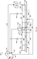
- FIG. 2A is an elevated view of an example pipe inspection system 200 with abutted pipe sections.
- a conveyor 220a moves a first pipe section 230a
- a conveyor 220b moves a second pipe section 230b past the inspection device 40 (e.g., an electromagnetic-type non-destructive testing device).
- the pipe section 230a has a pipe body 261a extending between a leading end 232a and a trailing end 234a.
- a blind zone 260a extends longitudinally inward from the leading end 232a, and a blind zone 260b extends longitudinally inward from the trailing end 234a.
- the pipe section 230b has a pipe body 261a extending between a leading end 232b and a trailing end 234b.
- a blind zone 260c extends longitudinally inward from the leading end 232b, and a blind zone 260d extends longitudinally inward from the trailing end 234b.
- the inspection device 40 is configured to inspect an axial section 250 of the pipe sections 230a and 230b as they pass through an inspection zone 252.
- a pipe position location device 222a e.g., an encoder, a break-beam detector, a proximity sensor
- a pipe position location device 222b is configured to sense the position of pipe sections as they enter the inspection zone 252.
- Pipe sections such as the pipe sections 230a and 230b have lengths of about 6m to 15m or more in length, and have diameters ranging from about 50mm to 300mm, or more specifically, from about 114mm to 244mm.
- a controller 202 includes input ports 203 configured to receive signals from the pipe location devices 222a and 222b, and provide conveyor control signals at output ports 204 configured for communication with the conveyors 220a and 220b.
- the controller 202 can control the speed of the conveyor 220a independently from the speed of the conveyor 220b.
- the conveyor 220a is controlled to convey pipe sections at a speed that is relatively slower than that of the conveyor 220b.
- the pipe section 230a is conveyed longitudinally at a slower speed than the pipe section 230b.
- the pipe section 230b has caught up to the pipe section 230a, and the leading end 232b is abutted against (e.g., physically contacts at least a portion of) the trailing end 234a to define an abutment 236.
- the process of abutting pipe sections will be discussed further in the descriptions of FIGs. 3A-3E .
- the blind zones 260b and 260c define an abutment zone 261.
- the inspection device 40 can accurately inspect the pipe sections 230a and 230b within the abutment zone 261.
- the blind zones 260b and 260c can be reduced from a range of about 300mm to 500mm inward from the trailing end 232a and the leading end 234b (e.g., as in FIGa. 1A-1B), down to about 3mm on each side of the abutment 236 for abutted pipe sections.
- FIG. 2B is a conceptual side view of example magnetic flux in the pipe inspection system 200.
- the pipe sections 230a is shown with an end 231a abutting the pipe section 230bb at an end 231b in the inspection zone 52.
- a magnetic field 70b is formed proximal to the inspection zone 52 as part of the inspection process, and the metal content of the pipe sections 230a and 230b interacts with the magnetic field 70b.
- the ends 231a and 231b are abutted, magnetic flux can pass between the pipe sections 230a and 230b with greater stability (e.g., compared to the unabutted end 31 of FIG. 1B ).
- the additional stability in the magnetic field 70b improves the ability of the inspection device 40 to provide more reliable, accurate, and/or usable measurements near the ends 231a and 231b, thus shrinking the blind zones 60 or allowing for inspection within a larger portion of the blind zones 60.
- the magnetic field in the area (generated by the machine) is stable and with the same characteristics than the magnetic field at the pipe body, also with the pipe sections 230a and 230b in end-to-end abutted contact, the leading end 232b does not physically present a blunt leading edge that can collide with the probe 41.
- the probe 41 does not need to be retracted from the pipe section 230a (e.g., thus creating a portion of the blind zone 260b) and repositioned upon the pipe section 230b (e.g., thus creating a portion of the blind zone 260c).
- the amount of vibration, bouncing, or oscillation of the probe caused by any discontinuities at the abutment 236 is relatively less than those caused by, for example, a full-on collision with the leading end 232b.
- the amount of time needed to dampen the oscillations and restore accurate inspection capability of the inspection device 40 is reduced, thus reducing the amount of longitudinal length of the pipe sections 230a and 230b that cannot be inspected near the trailing end 234a and the leading end 232b.
- the inspection device 40 provides sensor signals that are representative of the quality of the pipe section 230b at the axial section 250.
- the sensors signals vary with the quality of the pipe sections 230a, 230b.
- "normal” or “acceptable” axial sections 250 can be represented by a first signal level, while axial sections 250 having defects (e.g., distortions, voids, inclusions, bubbles, cracks) can result in relatively higher or lower signal levels.
- the sensor signals are received by the controller 202 at a sensor input port 206, and are processed to identify defects and other deformities in the pipe sections 230a, 230b.
- the controller 202 compares the received sensor signals against a predetermined defect threshold value (e.g., a calibration value provided by a user) to identify that a pipe section includes a defect of some type.
- a predetermined defect threshold value e.g., a calibration value provided by a user
- the inspection device 40 may provide a range of zero to 10v as sensor signals that vary with the quality of the axial section 250, in which a 5v output is considered nominal.
- a +/- 1v threshold window may be provided by an operator, in which signals that go outside the window (e.g., cause the signal to be less than 4v or greater than 6v) may be determined to be representative of a flaw.
- the inspection device 40 also provides sensor signals that are representative of the abutment 236 at the axial section 250.
- the sensors signals vary due to the discontinuity between the abutted pipe sections 230a, 230b.
- "normal" or "acceptable" axial sections 250 can be represented by a first signal level
- defects can be represented by a second signal level
- abutments can cause signal levels that appear as a significantly larger defect having a relatively larger third signal level.
- the controller 202 compares the received sensor signals against a predetermined abutment threshold value (e.g., a calibration value provided by a user) to identify when the abutment 236 is in the inspection zone 52.
- a predetermined abutment threshold value e.g., a calibration value provided by a user
- the inspection device 40 may provide a range of zero to 10v as sensor signals that vary with the quality of the axial section 250, in which a 5v output is considered nominal.
- a +/- 1v threshold window may be provided by an operator, in which signals that go outside the window (e.g., less than 4v or greater than 6v) may be determined to be representative of a flaw.
- signals that go outside the window e.g., less than 4v or greater than 6v
- signals that go outside the window e.g., less than 4v or greater than 6v
- sensor signals that exceed the abutment threshold value may be determined to be representative of the abutment 236 rather than a flaw.
- signals caused by abutments can be dismissed and the corresponding pipe section can be prevented from being identified as including a flaw.
- the controller 202 can process pipe location signals from the pipe location devices 222a and/or 222b and the sensor signals from the inspection device 40 to identify the locations of the pipe sections 230a, 230b, the abutment 236, and/or detected flaws.
- the controller 202 can be configured to identify the pipe section in which a flaw was detected.
- the controller 202 can identify the pipe section and the longitudinal location along that pipe section at which a flaw was detected.
- the controller 202 can identify the locations of the leading ends 232a, 232b and/or trailing ends 234a, 234b based on identified abutments 236 to determine the lengths and/or conveyor positions of the pipe sections 230a, 230b.
- the controller 202 provides a downstream control signal 265 at an output port 205.
- the downstream control signal 265 is received by a downstream controller 270 (e.g., programmable logic controller) configured to control subsequent operations.
- a downstream controller 270 e.g., programmable logic controller
- the downstream control signal 265 can identify the longitudinal locations of pipe flaws within the pipe sections 230a, 230b (e.g., flaws near the leading ends 232a, 232b and trailing ends 234a, 234b may simply be cut off, resulting in a slightly shorter pipe section not having the offending flaw).
- the downstream control signal 265 can identify the conveyor positions and/or lengths of the pipe sections 230a, 230b (e.g., position-dependent downstream operations may be coordinated based on the determined lengths and/or positions of the pipe sections).
- the downstream control signal 265 can identify the pass/fail status of the pipe sections 230a, 230b with respect to pipe flaws, and the downstream controller 270 can respond by causing flawed pipe sections to be segregated or otherwise differentiated (e.g., sent for rework, recycling, or disposal) from pipe sections that have not been identified as being flawed. An example of such segregation will be discussed in the descriptions of FIGs. 5A and 5B .
- FIGs. 3A-3E are block diagrams of an example pipe inspection system 300 and pipe sections at various stages of inspection.
- the pipe inspection system 300 can be the example pipe inspection system 200 of FIG. 2A .
- a pipe section 330a is conveyed longitudinally by a conveyor section 320a at a first speed.
- the conveyor section 320a includes one or more motors that can be controlled to control the speed at which pipe sections are transported.
- the pipe section 330a includes a blind zone 360a at a leading end 322a and a blind zone 260b at a trailing end 324a.
- each of the pipe sections 330a and 330b includes a blind zone 360 at a leading end 322a and at a trailing end 324a.
- the blind zones 360 can be about 300mm to 500mm long at the ends of their respective pipe sections.
- the pipe section 330b will catch up to the slower-moving pipe section 330a and abut the pipe section 330b at an abutment 336. Since the pipe section 330a and the pipe section 330b are in contact, the blind zones 360b and 360c will shrink lengthwise (e.g., from about 300mm to about 3mm) to become a blind zone portion 361a and a blind zone portion 361b.
- the abutted pair of pipe sections 330a and 330b then advance at the slower speed through an inspection device 340.
- the inspection device 340 inspects the pipe sections 330a and 330b, except the blind zones 361a, 361b. Since the blind zones 361a and 361b are smaller than the 360b and 360c, the inspection device 340 can inspect a relatively greater longitudinal length of the abutted pipe sections 330a and 330b than would be possible if the pipe sections 330a and 330b were inspected discretely. Meanwhile, a pipe section 330c is placed on the conveyor section 320a, behind the pipe section 330b, for transport at the first speed.
- the pipe section 330a has passed completely through the inspection device 340, and has reached a conveyor 320c.
- the conveyor section 320c includes one or more motors that can be controlled to control the speed at which pipe sections are transported.
- the conveyor section 320c is configured to transport pipe sections at a third speed that is relatively faster than the speed of the conveyor 320b. As such, the pipe section 330a is separated from being in abutment with the pipe section 330b.
- the pipe section 330c has come into abutment with the pipe section 330b.
- the blind zone 360b shrinks to become a blind zone 361b
- the pipe section 330c includes a similarly reduced blind zone 361c.
- the blind zone 360a remained relatively large (e.g., >300mm).
- the pipe section 330a can be returned to the conveyor 320a for reprocessing.
- the pipe section 330a will catch up to and abut the pipe section 330c, thus allowing the leading end 322a of the pipe section 330a to be inspected with a relatively smaller blind zone (e.g., down to about 3mm from the leading end 322a).
- the pipe section 330a may have threaded ends, and the leading end 322a may be temporarily mated with a short section of complementarily-threaded pipe that is configured to have a length and/or shape that allows the inspection device 340 to accurately inspect the leading end 322a with a reduced blind zone (e.g., long enough to let vibrations in the example sensor probe 41 of FIG. 2A to dampen out before the leading end 322a arrives at the location of the sensor probe 41).
- a reduced blind zone e.g., long enough to let vibrations in the example sensor probe 41 of FIG. 2A to dampen out before the leading end 322a arrives at the location of the sensor probe 41.
- a "dummy" pipe section may be added before the first pipe section on the line (e.g., ahead of the leading end 322a) and/or behind the last pipe section on the line to provide abutment and therefore the tighter blind zones for the pipe sections against which the "dummy" sections abut.
- Such "dummy" pipe sections may then be reused at the starts and ends of subsequent inspection processes, rather than being passed along as finished product.
- FIG. 4 shows a chart of an example speed profile 400 of a pipe section in a pipe inspection system.
- the speed profile 400 can represent the speeds at which the example pipe section 330a is transported through the example pipe inspection system 300 of FIGs. 3A-3E .
- a pipe section is transported at a first (e.g., "fast") speed.
- the pipe section 330a can be transported relatively quickly along the conveyor 320a.
- the pipe section is transported at a second (e.g., "nominal") speed.
- the pipe section 330a can be transported at a nominal speed along the conveyor 320b at a speed that is slower than that provided by the conveyor 320a.
- the pipe section is transported at a third (e.g., "faster") speed.
- the pipe section 330a can be transported away from the conveyor 320b by the conveyor 320c at a speed that is relatively faster than the nominal speed.
- FIGs. 5A and 5B are block diagrams of an example pipe inspection system 500 and a post-inspection pipe segregation system 501.
- the example pipe inspection system 500 can be part of the example pipe inspection systems 200 or 300 of FIGs 2A-3E .
- the post-inspection pipe segregation system 501 can be added downstream from the example pipe inspection systems 200 or 300.
- a collection of pipe sections 530 are abutted for inspection by an inspection device 540.
- the post-inspection pipe segregation system 501 includes a conveyor section 510 that is moveable to direct inspected pipe section 530 to a first output conveyor 520 or a second output conveyor 522.
- the post-inspection pipe segregation system 501 is configured to move the conveyor section 510 based, at least in part, on defect signals provided by the inspection device 540.
- the inspection device 540 can perform an electromagnetic inspection as the abutted pipe sections 530 are conveyed relative to the inspection device, and provide defect data that describes defects detected along the pipe sections 530 including within reduced blind zone defined about abutments between the pipe sections 530.
- the defect data can be processed by a controller (e.g., the example controller 202 of FIG. 2A ) to identify pipe sections that have defects, and send control signals downstream to the post-inspection pipe segregation system 501.
- the post-inspection pipe segregation system 501 can include and/or be controlled by the example downstream controller 270 of FIG. 2A .
- a pipe section 531 has been identified as having no defects detected by the inspection device 540, including no defects from about 300mm to about 3mm of the leading or trailing ends of the pipe section 531.
- the post-inspection pipe segregation system 501 aligns the conveyor section 510 with the first output conveyor 520 (e.g., a "passed inspection" conveyor).
- the first output conveyor 520 can transport the pipe section 531 for additional processing steps, such as subsequent inspection or processing steps toward a final product.
- a pipe section 532 has been identified as having at least one defect detected by the inspection device 540, including defects detected within about 300mm to about 3mm of the leading and/or trailing ends of the pipe section 532.
- the post-inspection pipe segregation system 501 aligns the conveyor section 510 with the second output conveyor 522 (e.g., a "failed inspection" conveyor).
- the second output conveyor 522 can transport the pipe section 531 for additional processing steps, such as segregating the pipe section from becoming a final product or directing the pipe section 532 for reprocessing, recycling, or disposal.
- FIG. 6 is flow chart that shows an example of a process 600 for inspecting pipe sections.
- the process 600 may be performed by the example pipe inspection systems 200, 300, and/or 500 of FIGs. 2 , 3A-3E , and 5A-5B .
- a first pipe section having a first pipe body, a first leading end, and a first trailing end is provided.
- the pipe section 230a can be placed on the conveyor 220a.
- the pipe section 330a can be placed on the conveyor 320a.
- a second pipe section having a second pipe body, a second leading end, and a second trailing end is provided.
- the pipe section 230b can be placed on the conveyor 220b.
- the pipe section 330b can be placed on the conveyor 320a behind the pipe section 330a.
- the second leading end is abutted to the first trailing end to define a pipe abutment zone comprising a portion of the first pipe section measured longitudinally from the first trailing end a longitudinal distance of 300 mm and a portion of the second pipe section measured longitudinally from the second leading end a longitudinal distance of 300 mm.
- the pipe section 330b catches up to an abuts the pipe section 330a such that there is a blind zone 361a and a blind zone 361b on the longitudinal sides of the abutment 336.
- abutting the second leading end to the first trailing end to define a pipe abutment zone can include conveying the first pipe section longitudinally at the first speed, conveying the second pipe section longitudinally at a second speed that is faster than the first speed, contacting the second leading end to the first trailing end to define the pipe abutment zone, and conveying the first pipe section and the second pipe section longitudinally such that contact between the first trailing end and the second leading end is maintained.
- the conveyor 320b operates at a slower speed than the conveyor 320a. As such the pipe section 330b will catch up to and contact the pipe section 330a, and the conveyor 320b will convey the abutted pipe sections 330a, 330b at the slower speed.
- the first pipe section and the second pipe section are conveyed longitudinally at a first speed relative to an inspection device configured to perform an electromagnetic inspection.
- the abutted pipe sections 330a and 330b are conveyed by the conveyor 320b through the inspection device 340 at a nominal speed (e.g., phase 420 of FIG. 4 ).
- inspecting the first portion of the abutment zone comprises inspecting a portion of the first pipe section measured longitudinally from the first trailing end a longitudinal distance of 3 mm to 300 mm and inspecting the second portion of the abutment zone comprises inspecting a portion of the second pipe section measured longitudinally from the second leading end a longitudinal distance of 3 mm to 300 mm.
- the pipe inspection device 40 can inspect an axial section 250 as the pipe sections 230a and 230b pass through the inspection zone 52. Since the pipe sections 230a and 230b are in end-to-end contact, the pipe inspection device 40 can detect defects as close as 3mm from each side of the abutment 236.
- defect data that describes defects detected within at least one of the first portion and the second portion of pipe abutment zone providing, based on the inspecting by the inspection device.
- the inspection device 40 can output defect sensor signals to the controller 202.
- the process 600 generally describes inspection near the ends of the pipe sections that are generally not available when inspecting individual pipe sections (e.g., inspecting pipes one at a time rather than in a pseudo-continuous manner as described herein), the process 600 is not limited to the inspection of the abutment zones only. In some implementations, the process 600 can also include inspecting the pipe body that extends between the pipe ends. For example, the process 600 can inspect the pipe body 261a of the example pipe section 230a of FIGs. 2A-2B along with the leading end 232a and the trailing end 234a as each passes by the pipe inspection device 40.
- the method 600 can also include conveying, after inspecting the pipe abutment zone, the first pipe section longitudinally at a third speed that is faster than the second speed.
- FIG. 3E shows that after the pipe section 330a has been inspected, the conveyor 320c can carry the pipe section 330a away at a speed that is faster than that of the conveyor 320b.
- the process 600 can also include providing a third pipe section having a third pipe body, a third leading end, and a third trailing end, abutting the third leading end to the second trailing end to define a second pipe abutment zone comprising a portion of the second pipe section measured longitudinally from the second trailing end a longitudinal distance of 300 mm and a portion of the third pipe section measured longitudinally from the third leading end a longitudinal distance of 300 mm, conveying the second pipe section and the third pipe section longitudinally at the first speed relative to the inspection device, inspecting, by the inspection device as the second pipe section and the third pipe section are conveyed relative to the inspection device, the second abutment zone, and providing, based on the inspecting, defect data that describes defects detected within the second pipe abutment zone by the inspection device.
- the pipe section 330c can be brought into end-to-end contact with the pipe section 330b for inspection by the inspection device 340.
- the process 600 can also include inspecting, by the inspection device as the first pipe section is conveyed relative to the inspection device, a portion of the first pipe body, and inspecting, by the inspection device as the second pipe section is conveyed relative to the inspection device, a portion of the second pipe body.
- the inspection device 40 can inspect the pipe sections 230a and 230b, including portions of the pipe bodies 261a and 261b. With reference to FIG. 3C , the inspection can be made within regions of the blind zones 360b and 360c that exclude the reduced blind zones 361a and 361b.
- the inspection can include creating a magnetic field proximal an axial pipe section, detecting an interaction of the magnetic field with the axial pipe section, and detecting a variance of the interaction at the axial pipe section.
- the inspection devices 40, 340, and/or 540 can function using the principle of dispersed electromagnetic flow.
- the process 600 can include determining that the variance exceeds a predetermined defect threshold value, identifying one of the first pipe section or the second pipe section as having the axial pipe section that caused the variance as a defective pipe section, and segregating the defective pipe section from other pipe sections not identified as defective pipe sections wherein the axial pipe section is less than 300mm away from the first trailing end or the second leading end.
- the controller 202 can be configured (e.g., calibrated) with a threshold value that represents a minimum sensor variance that can indicate the presence of a defect sensed by the inspection device 40.
- the controller 202 can identify the pipe section in which the defect was detected and trigger the post-inspection pipe segregation system 501 to direct the defective pipe section away from the output conveyor 520 and toward the output conveyor 521.
- the process 600 can include determining that the variance exceeds a predetermined defect threshold value, receiving position information of at least one of the first pipe section and the second pipe section, identifying one of the first pipe section or the second pipe section as having the axial pipe section that caused the variance as a defective pipe section, and identifying, based on the position information, the position of the axial pipe section along the defective pipe section, providing defect information that identifies the defective pipe section and the identified position of the axial pipe section where the variance exceeded the defect threshold value, wherein the identified position is in the pipe abutment zone of the first pipe section and the second pipe section.
- the controller 202 can be configured (e.g., calibrated) with a threshold value that represents a minimum sensor variance that can indicate the presence of a defect sensed by the inspection device 40. If the sensor signals received from the inspection device vary by, or exceed, the threshold value, then the controller 202 can identify the pipe section in which the defect was detected and identify the location of the defect along the length of the pipe section in which the defect was detected. In some implementations, if the defect is located within a predetermined distance from the end of a pipe section, the pipe section may be reworked to remove the defect. For example, if a 10m long pipe section has a defect 15cm from the end, the end may simply be cut of about 25cm from the end, resulting in a 9.75m pipe section without the defect.
- the process 600 can include receiving position information of the first pipe section and the second pipe section, determining that the variance exceeds a predetermined abutment threshold value, identifying, based on the position information, the position of the axial pipe section where the variance exceeded the abutment threshold value, providing the identified position as first position information representative of a location of the first trailing end, and providing the identified position as second position information representative of a location of the second leading end.
- the abutment 236, when encountered by the probe 41, may cause a variance in the sensor signals output by the pipe inspection device 40. This variance can be larger than that of any expected pipe defect.
- the controller 202 can be configured (e.g., calibrated) with a threshold value that can be used to distinguish between defects and abutments. For example, axial sections having no defects may cause sensor signals to have little variance about a predetermined nominal value, while defects can cause variances that exceed a defect threshold but do not exceed an abutment threshold value, and abutment can cause variances that exceed both the defect threshold value and the abutment threshold value.
- the controller 202 can determine that an abutment has been detected, and based on position signals from the pipe location devices 222a and/or 222b, identify the location of the detected abutment. Since the abutment (e.g., the abutment 236) is defined by the point where a pipe section trailing end (e.g., the trailing end 234a) contacts a subsequent pipe section's leading end (e.g., the leading end 232b), the locations of the trailing end and the leading end can also be determined and provided to other controllers (e.g., the downstream controller 270) to coordinate other operations.
- the abutment e.g., the abutment 236
- the abutment e.g., the abutment 236
- the locations of the trailing end and the leading end can also be determined and provided to other controllers (e.g., the downstream controller 270) to coordinate other operations.
- the process 600 can also include receiving, by a controller, at least one of the first position information and the second position information, and controlling, by the controller and after inspecting the pipe abutment zone, a process based at least one of the first position information and the second position information.
- the process can be one of a motion control process, a longitudinal electromagnetic longitudinal defect inspection process, an ultrasonic pipe thickness inspection process, a transversal defect inspection process, or a machine vision based inspection process.
- the controller 202 can process sensor signal information from the pipe inspection device 40 and process position feedback signals from the pipe location devices 222a, 222b, and provide the downstream control signal 265 to the downstream controller 270, which may be configured to control the post-inspection pipe segregation system 501.
- the downstream controller 270 can be configured to control other longitudinal electromagnetic longitudinal defect inspection processes, pipe thickness inspection processes (e.g., ultrasonic), machine vision-based inspection processes, automation processes, or any other appropriate process for manufacturing or inspecting pipe sections.
- FIG. 7 is a schematic diagram of an example of a generic computer system 700.
- the system 700 can be used for the operations described in association with the method 300 according to one implementation.
- the system 700 may be included in either or all of the controller 202, the downstream controller 270, the pipe inspection devices 40, 340, and 540, the pipe location devices 222a and 222b, and the post-inspection pipe segregation system 501.
- the system 700 includes a processor 710, a memory 720, a storage device 730, and an input/output device 740. Each of the components 710, 720, 730, and 740 are interconnected using a system bus 750.
- the processor 710 is capable of processing instructions for execution within the system 700. In one implementation, the processor 710 is a single-threaded processor. In another implementation, the processor 710 is a multi-threaded processor.
- the processor 710 is capable of processing instructions stored in the memory 720 or on the storage device 730 to display graphical information for a user interface on the input/output device 740.
- the memory 720 stores information within the system 700.
- the memory 720 is a computer-readable medium.
- the memory 720 is a volatile memory unit.
- the memory 720 is a non-volatile memory unit.
- the storage device 730 is capable of providing mass storage for the system 700.
- the storage device 730 is a computer-readable medium.
- the storage device 730 may be a floppy disk device, a hard disk device, an optical disk device, or a tape device.
- the input/output device 740 provides input/output operations for the system 700.
- the input/output device 740 includes a keyboard and/or pointing device.
- the input/output device 740 includes a display unit for displaying graphical user interfaces.
- the features described can be implemented in digital electronic circuitry, or in computer hardware, firmware, software, or in combinations of them.
- the apparatus can be implemented in a computer program product tangibly embodied in an information carrier, e.g., in a machine-readable storage device for execution by a programmable processor; and method steps can be performed by a programmable processor executing a program of instructions to perform functions of the described implementations by operating on input data and generating output.
- the described features can be implemented advantageously in one or more computer programs that are executable on a programmable system including at least one programmable processor coupled to receive data and instructions from, and to transmit data and instructions to, a data storage system, at least one input device, and at least one output device.
- a computer program is a set of instructions that can be used, directly or indirectly, in a computer to perform a certain activity or bring about a certain result.
- a computer program can be written in any form of programming language, including compiled or interpreted languages, and it can be deployed in any form, including as a stand-alone program or as a module, component, subroutine, or other unit suitable for use in a computing environment.
- Suitable processors for the execution of a program of instructions include, by way of example, both general and special purpose microprocessors, and the sole processor or one of multiple processors of any kind of computer.
- a processor will receive instructions and data from a read-only memory or a random access memory or both.
- the essential elements of a computer are a processor for executing instructions and one or more memories for storing instructions and data.
- a computer will also include, or be operatively coupled to communicate with, one or more mass storage devices for storing data files; such devices include magnetic disks, such as internal hard disks and removable disks; magneto-optical disks; and optical disks.
- Storage devices suitable for tangibly embodying computer program instructions and data include all forms of non-volatile memory, including by way of example semiconductor memory devices, such as EPROM, EEPROM, and flash memory devices; magnetic disks such as internal hard disks and removable disks; magneto-optical disks; and CD-ROM and DVD-ROM disks.
- semiconductor memory devices such as EPROM, EEPROM, and flash memory devices
- magnetic disks such as internal hard disks and removable disks
- magneto-optical disks and CD-ROM and DVD-ROM disks.
- the processor and the memory can be supplemented by, or incorporated in, ASICs (application-specific integrated circuits).
- ASICs application-specific integrated circuits
- the features can be implemented on a computer having a display device such as a CRT (cathode ray tube) or LCD (liquid crystal display) monitor for displaying information to the user and a keyboard and a pointing device such as a mouse or a trackball by which the user can provide input to the computer.
- a display device such as a CRT (cathode ray tube) or LCD (liquid crystal display) monitor for displaying information to the user and a keyboard and a pointing device such as a mouse or a trackball by which the user can provide input to the computer.
- the features can be implemented in a computer system that includes a back-end component, such as a data server, or that includes a middleware component, such as an application server or an Internet server, or that includes a front-end component, such as a client computer having a graphical user interface or an Internet browser, or any combination of them.
- the components of the system can be connected by any form or medium of digital data communication such as a communication network. Examples of communication networks include, e.g., a LAN, a WAN, and the computers and networks forming the Internet.
- the computer system can include clients and servers.
- a client and server are generally remote from each other and typically interact through a network, such as the described one.
- the relationship of client and server arises by virtue of computer programs running on the respective computers and having a client-server relationship to each other.
Landscapes
- Chemical & Material Sciences (AREA)
- General Health & Medical Sciences (AREA)
- Pathology (AREA)
- Physics & Mathematics (AREA)
- Health & Medical Sciences (AREA)
- Life Sciences & Earth Sciences (AREA)
- Analytical Chemistry (AREA)
- Electrochemistry (AREA)
- General Physics & Mathematics (AREA)
- Biochemistry (AREA)
- Immunology (AREA)
- Chemical Kinetics & Catalysis (AREA)
- Investigating Or Analyzing Materials By The Use Of Magnetic Means (AREA)
- Investigating Materials By The Use Of Optical Means Adapted For Particular Applications (AREA)
- Engineering & Computer Science (AREA)
- Mechanical Engineering (AREA)
Description
- This application claims priority to
U.S. Patent Application No. 15/702,389 filed on September 12, 2017 - This instant specification relates generally to non-destructive testing of pipe sections and more particularly electromagnetic inspection of abutment zones of adjacent pipe sections.
- Electromagnetic type testing is used to analyze defects in tubes and pipes. Such testing is used for inspection during manufacturing (e.g., quality control) and/or during receiving by a company or consumer (e.g., incoming inspection). This type of testing has relatively high sensitivity, can be automated, can enable automatic classification of the inspected pipe (e.g., accept/reject, pass/fail, good/bad), and increase throughput.
- Electromagnetic type testing allows inspection of the walls of the pipe to detect and locate defects, either internal or external, by contacting electromagnetic probes with the object under testing. This testing is standardized in many countries, and the requirements for such testing are listed by the standards provided by the American Petroleum Institute (API) (USA), Deutsches Institut für Normung (DIN) (Germany), and Gosudarstvennyy Standart (GOST) (Russia). Basic standard parameters are described by the international standard ISO9402.
- A number of companies manufacture a variety of instruments applicable to Electromagnetic testing, such as the Dr. Foerster Institute of Germany with its defect detectors "Rotomat/Transomat", the defect detector "Amalog/Sonoscope" from the company "Tuboscope/ National Oilwell Varco", USA, and the defect detector VMD-30N from MSIA, Russia among others. Further devices and methods are known from
US 2017/160236 A1 , which describes the detection of defects in pipes based on magnetic flux leakage testing. - In general, this document describes non-destructive testing of pipe sections and more particularly electromagnetic inspection of abutment zones of adjacent pipe sections.
- In a first aspect, a method of pipe inspection, as defined by claim 1, includes providing a first pipe section having a first pipe body, a first leading end, and a first trailing end, providing a second pipe section having a second pipe body, a second leading end, and a second trailing end, abutting at least a portion of the second leading end to at least a portion of the first trailing end to define a pipe abutment zone comprising a portion of the first pipe section measured longitudinally from the first trailing end a longitudinal distance of 300 mm and a portion of the second pipe section measured longitudinally from the second leading end a longitudinal distance of 300 mm, conveying the first pipe section and the second pipe section longitudinally at a first speed relative to an inspection device configured to perform an electromagnetic inspection, inspecting, by the inspection device as the first pipe section and the second pipe section are conveyed relative to the inspection device, a first portion of the pipe abutment zone and a second portion of the pipe abutment zone, and providing, based on the inspecting, defect data that describes defects detected within at least one of the first portion and the second portion of the pipe abutment zone by the inspection device, wherein the inspection device functions using the principle of dispersed electromagnetic flow and the inspection comprises:creating a magnetic field proximal an axial pipe section;detecting an interaction of the magnetic field with the axial pipe section; and detecting a variance of the interaction at the axial pipe section.
- Various implementations include some, all, or none of the following features. Abutting the second leading end to the first trailing end to define a pipe abutment zone can include conveying the first pipe section longitudinally at the first speed, conveying the second pipe section longitudinally at a second speed that is faster than the first speed, contacting the second leading end to the first trailing end to define the pipe abutment zone, and conveying the first pipe section and the second pipe section longitudinally such that contact between the first trailing end and the second leading end is maintained. The method can include conveying, after inspecting the pipe abutment zone, the first pipe section longitudinally at a third speed that is faster than the second speed. The method can include providing a third pipe section having a third pipe body, a third leading end, and a third trailing end, abutting at least a portion the third leading end to at least a portion of the second trailing end to define a second pipe abutment zone comprising a portion of the second pipe section measured longitudinally from the second trailing end a longitudinal distance of 300 mm and a portion of the third pipe section measured longitudinally from the third leading end a longitudinal distance of 300 mm, conveying the second pipe section and the third pipe section longitudinally at the first speed relative to the inspection device, inspecting, by the inspection device as the second pipe section and the third pipe section are conveyed relative to the inspection device, the second pipe abutment zone, and providing, based on the inspecting, defect data that describes defects detected within the second pipe abutment zone by the inspection device. The method can include inspecting, by the inspection device as the first pipe section is conveyed relative to the inspection device, a portion of the first pipe body, and inspecting, by the inspection device as the second pipe section is conveyed relative to the inspection device, a portion of the second pipe body. The inspection can include creating a magnetic field proximal an axial pipe section, detecting an interaction of the magnetic field with the axial pipe section, and detecting a variance of the interaction at the axial pipe section. The method can include determining that the variance exceeds a predetermined defect threshold value, identifying one of the first pipe section or the second pipe section as having the axial pipe section that caused the variance as a defective pipe section, and segregating the defective pipe section from other pipe sections not identified as defective pipe sections, and wherein the axial pipe section is less than 300mm away from the first trailing end or the second leading end. The method can include determining that the variance exceeds a predetermined defect threshold value, receiving position information of at least one of the first pipe section and the second pipe section, identifying one of the first pipe section or the second pipe section as having the axial pipe section that caused the variance as a defective pipe section, and identifying, based on the position information, an identified position of the axial pipe section along the defective pipe section, and providing defect information that identifies the defective pipe section and the identified position of the axial pipe section where the variance exceeded the predetermined defect threshold value, wherein the identified position is in the pipe abutment zone of the first pipe section and the second pipe section. The method can also include receiving position information of the first pipe section and the second pipe section, determining that the variance exceeds a predetermined abutment threshold value, identifying, based on the position information, an identified position of the axial pipe section where the variance exceeded the predetermined abutment threshold value, providing the identified position as first position information representative of a location of the first trailing end, and providing the identified position as second position information representative of a location of the second leading end. The method can also include receiving, by a controller, at least one of the first position information and the second position information, and controlling, by the controller and after inspecting the pipe abutment zone, a process based at least one of the first position information and the second position information. The process can be one of a motion control process, a longitudinal electromagnetic longitudinal defect inspection process, an ultrasonic pipe thickness inspection process, a transversal defect inspection process, or a machine vision based inspection process. Inspecting the first portion of the pipe abutment zone can include inspecting a portion of the first pipe section measured longitudinally from the first trailing end a longitudinal distance of 3 mm to 300 mm and inspecting the second portion of the abutment zone comprises inspecting a portion of the second pipe section measured longitudinally from the second leading end a longitudinal distance of 3 mm to 300 mm.
- In a second aspect, a computer program stored in a computer readable storage device, as defined by claim 13, includes instructions that when executed by a computer system cause the computer system to perform electromagnetic inspection operations on a first pipe section having a first pipe body, a first leading end, and a first trailing end and a second pipe section in at least partial abutment with a second pipe body having a second leading end, and a second trailing end, said inspection operations including receiving pipe defect signals from an electromagnetic pipe inspection device, the electromagnetic pipe inspection device functioning using the principle of dispersed electromagnetic flow; receiving pipe position signals from a pipe position location device, providing conveyor control signals to control a pipe conveyor to abut at least a portion of the second leading end to at least a portion of the first trailing end to define a pipe abutment zone comprising a portion of the first pipe section measured longitudinally from the first trailing end a longitudinal distance of 300 mm and a portion of the second pipe section measured longitudinally from the second leading end a longitudinal distance of 300 mm, such that the inspection device inspects a first portion of the pipe abutment zone and a second portion of the pipe abutment zone as the first pipe section and the second pipe section are conveyed relative to the inspection device, detecting a pipe defect location in the abutment zone based on the received pipe defect signals, received pipe position signals, and a predetermined pipe defect threshold value, identifying a defective pipe section based on the pipe defect location, and providing an identity of the defective pipe section.
- Various implementations can include some, all, or none of the following features. The operations can include detecting a pipe abutment location based on received pipe defect signals, received pipe position signals, and a predetermined pipe abutment threshold value that is different from the predetermined pipe defect threshold value, and providing a pipe end position signal based on the pipe abutment location, representative of a location of an abutment between a pipe section leading end and a pipe section trailing end. The operations can include providing a conveyor control signal that causes a first section of pipe conveyor to operate at a first speed, and providing a conveyor signal that causes a second section of pipe conveyor, operationally downstream from the first section of pipe conveyor, to operate at a second speed that is slower than the first speed, wherein the pipe inspection device is arranged along the second section of pipe conveyor. The operations can include determining, based on pipe position signals, that a first pipe section on the first section of pipe conveyor has abutted a second pipe section on the second section of pipe conveyor, and providing a second conveyor control signal that causes the first section of pipe conveyor to operate at approximately the second speed. Detecting a pipe defect location based on received pipe defect signals, received pipe position signals, and the predetermined defect threshold value can include receiving position information of at least one of a first pipe section having a trailing end and a second pipe section having a leading end longitudinally abutting the trailing end, and determining that a variance in the pipe defect signals exceeds the predetermined pipe defect threshold value, wherein the variance is detected less than 300mm away from the first trailing end or the second leading end, and wherein identifying a defective pipe section based on the pipe defect location further comprises identifying one of the first pipe section or the second pipe section as having caused the variance. Detecting a pipe abutment location can include receiving position information of at least one of a first pipe section having a trailing end and a second pipe section having a leading end longitudinally at least partially abutting the trailing end, determining that a variance in the pipe defect signals exceeds a predetermined pipe abutment threshold value, wherein the variance is detected less than about 3mm away from the first trailing end or the second leading end, and identifying, based on the position information, an identifying position where the variance exceeded the predetermined abutment threshold value, and wherein providing the pipe end position signal further comprises providing the identified position as a pipe end position.
- In a third aspect, a system for pipe inspection, as defined by claim 19, includes an electromagnetic pipe inspection device, functioning using the principle of dispersed electromagnetic flow, a conveyor, configured to convey a first pipe section and a second pipe section longitudinally relative to the inspection device, the first pipe section having a first pipe body, a first leading end, and a first trailing end and the second pipe section having a second pipe body, a second leading end, and a second trailing end, a pipe position location device, and a controller having a defect signal input port configured to receive pipe defect signals from the pipe inspection device, a position input port configured to receive pipe position signals from the pipe position location device, and a processor configured to provide conveyor control signals to control the conveyor to abut at least a portion of the second leading end to at least a portion of the first trailing end to define a pipe abutment zone comprising a portion of the first pipe section measured longitudinally from the first trailing end a longitudinal distance of 300 mm and a portion of the second pipe section measured longitudinally from the second leading end a longitudinal distance of 300 mm, such that the inspection device inspects a first portion of the pipe abutment zone and a second portion of the pipe abutment zone as the first pipe section and the second pipe section are conveyed relative to the inspection device, and to detect a pipe defect location based on pipe defect signals, pipe position signals, and a predetermined pipe defect threshold value, and provide the pipe defect location as a pipe defect location signal at a first output port, wherein the pipe defect location signal identifies pipe sections having pipe defects.
- Various embodiments can include some, all, or none of the following features. The processor can be configured to detect a pipe abutment location based on pipe defect signals, pipe position signals, and a predetermined pipe abutment threshold, and provide a pipe end position signal at a second output port, wherein the pipe end position signal identifies a location of at least one of a pipe section leading end and a pipe section trailing end. The system can include a conveyor configured to convey pipe sections longitudinally, the conveyor comprising first motor configured to convey pipe sections along an upstream section of the conveyor a first speed, and a second motor configured to convey pipe sections along a downstream section of the conveyor at a second speed that is slower than the first speed. At least one of the first motor and the second motor can be configured to convey pipe sections based on a speed signal received from a motor control output port of the controller, and wherein the processor can be further configured to provide the speed signal such that the second speed is less than the first speed. The conveyor can include a third motor configured to convey pipe sections along an output section of the conveyor at a third speed that is faster than the second speed.
- The systems and techniques described here may provide one or more of the following advantages. First, a system can improve the capabilities of existing pipe inspection devices. Second, the system can transform a discrete or batch inspection process into one that emulates a continuous process. Third, the system can increase the service lifetime of pipe inspection devices by reducing wear. Fourth, the system can increase the efficiency of pipe inspection processes by enabling automated inspection processes to inspect relatively greater portions of pipe sections than has been done previously.
- The details of one or more implementations are set forth in the accompanying drawings and the description below. Other features and advantages will be apparent from the description and drawings, and from the claims.
-
-
FIG. 1A is an elevated view of an example of a prior art pipe inspection system with blind zones proximal to the ends of the pipe being inspected. -
FIG. 1B is a conceptual side view of example magnetic flux in a prior art pipe inspection system. -
FIG. 2A is an elevated view of an example pipe inspection system with abutted pipe sections. -
FIG. 2B is a conceptual side view of example magnetic flux in an example pipe inspection system with abutted pipe sections. -
FIGs. 3A-3E are block diagrams of an example pipe inspection system and pipe sections at various stages of inspection. -
FIG. 4 shows a chart of an example speed profile of a pipe section in a pipe inspection system. -
FIGs. 5A and 5B are block diagrams of an example pipe inspection system and post- inspection pipe segregation system. -
FIG. 6 is flow chart that shows an example of a process for inspecting pipe sections. -
FIG. 7 is a schematic diagram of an example of a generic computer system. - This document describes systems and techniques for performing non-destructive testing of pipe sections. In general, the capabilities of existing electromagnetic type pipe inspection systems are limited in their ability to inspect near the ends of discrete pipe sections. As will be explained below, the ability of these systems to inspect near the ends of pipes can be improved by arranging two or more discrete pipe sections such that the pipe sections are in end-to-end contact during inspection.
-
FIG. 1A is an elevated view of an example of a prior artpipe inspection system 10. - In the
pipe inspection system 10, aconveyor 20 moves afirst pipe section 30a and asecond pipe section 30b past an inspection device 40 (e.g., a magnetic-type non-destructive testing device). Theinspection device 40 is configured to inspect anaxial section 50 of thepipe sections inspection zone 52. Pipe sections such as thepipe sections - In some embodiments, the
inspection device 40 can detect internal and external defects in pipe sections using the principle of dispersed electromagnetic flow (e.g., electromagnetic inspection). By means of an adjustable DC current, thepipe section 30a is magnetized to its longitudinal axis. Transversal Defects or discontinuities in thepipe section 30a generate disperse electromagnetic flows. Asensor probe 41 contacts the pipe, and an induction coil housed in thesensor probe 41 detects these flows. The signals captured by theprobe 41 are processed and analyzed to determine the type of defect. - In some embodiments, the
inspection device 40 can be a rotating non-destructive testing device that utilizes electromagnetic principles to detect the presence of longitudinal discontinuities in pipe sections. Such examples also use the disperse flow principle. For example, thepipe section 30a can be magnetized transversely to its axis by an alternating magnetic field. The penetration is very low since it is concentrated around the circumference of the pipe due to the skin effect, in which the outer and inner surfaces are magnetically saturated. Such magnetization occurs without contact with thepipe section 30a by means of two alternating field yokes, which are assembled together with the detection coils on the arms. The assembly is mounted on a rotating head and rotates about the pipe to perform the inspection. Discontinuities and defects on the tube create a disperse flow, and this flow can be captured by the detection coils, and turned into signals that are processed and analyzed to identify the nature of the defect. - Such inspection devices, when used to inspect pipe sections have blind zones 60 (e.g., dead zones) at end portions of the pipe sections where the pipes cannot be accurately inspected. In some cases, for inspection devices configured to inspect pipe sections having lengths of 6m to 15m or more and/or diameters ranging from about 50mm to 300mm, the
blind zones 60 can be about 300mm to 500mm long at each end of a pipe section. - The blind zone phenomenon is caused by the inability of the equipment to ensure a stable magnetic field in the zone and correct contact of the probes on the pipe body.
FIG. 1B is a conceptual side view of example magnetic flux in thepipe inspection system 10. In the illustrated example, thepipe section 30a is shown with an end 31 entering theinspection zone 52. Amagnetic field 70a is formed proximal to theinspection zone 52 as part of the inspection process, and the metal content of thepipe section 30a interacts with themagnetic field 70a. The end 31 however, causes instability in themagnetic field 70a, which can cause readings from theinspection device 40 to be unreliable or unusable near the end 31, creating theblind zone 60. In other examples, the probe(s) of theinspection device 40 can be open before thepipe section 30a enters. Thepipe section 30a can enter the inspection device at high speed, but just as theprobe 41 makes contact with the surface of the pipe section, theblind zone 60 at the leading end of the pipe section has already passed theprobe 41 and as such the section of pipe in theblind zone 60 may not get inspected. In other examples, theprobe 41 may be initially positioned away from contact or proximity with thepipe section 30a (e.g., to prevent longitudinal collision with the leading end of thepipe section 30a) and may then be brought into contact or proximity with thepipe section 30a after the leading end has passed. However, some time is required to reposition theprobe 41, which allows a length of thepipe section 30a to pass (e.g., the blind zone 60) before sensing can begin. In yet another example, theprobe 41 may be constructed to endure a collision with the leading end of thepipe section 30a, however such collisions can cause theprobe 41 to bounce and/or vibrate (e.g., oscillate). The sensing ability of theprobe 41 is diminished until these vibrations dampen out, and the amount of time needed for such damping can allow theblind zone 60 to pass. -
FIG. 2A is an elevated view of an examplepipe inspection system 200 with abutted pipe sections. In thepipe inspection system 200, aconveyor 220a moves afirst pipe section 230a, and aconveyor 220b moves asecond pipe section 230b past the inspection device 40 (e.g., an electromagnetic-type non-destructive testing device). Thepipe section 230a has apipe body 261a extending between aleading end 232a and a trailingend 234a. Ablind zone 260a extends longitudinally inward from theleading end 232a, and a blind zone 260b extends longitudinally inward from the trailingend 234a. Thepipe section 230b has apipe body 261a extending between aleading end 232b and a trailingend 234b. Ablind zone 260c extends longitudinally inward from theleading end 232b, and ablind zone 260d extends longitudinally inward from the trailingend 234b. - The
inspection device 40 is configured to inspect an axial section 250 of thepipe sections position location device 222a (e.g., an encoder, a break-beam detector, a proximity sensor) is configured to sense the position of pipe sections as they exit the inspection zone 252, and a pipeposition location device 222b is configured to sense the position of pipe sections as they enter the inspection zone 252. Pipe sections such as thepipe sections - A
controller 202 includesinput ports 203 configured to receive signals from thepipe location devices output ports 204 configured for communication with theconveyors controller 202 can control the speed of theconveyor 220a independently from the speed of theconveyor 220b. - The
conveyor 220a is controlled to convey pipe sections at a speed that is relatively slower than that of theconveyor 220b. As such, in the illustrated example, thepipe section 230a is conveyed longitudinally at a slower speed than thepipe section 230b. Thepipe section 230b has caught up to thepipe section 230a, and theleading end 232b is abutted against (e.g., physically contacts at least a portion of) the trailingend 234a to define anabutment 236. The process of abutting pipe sections will be discussed further in the descriptions ofFIGs. 3A-3E . - With the
pipe sections blind zones 260b and 260c define anabutment zone 261. Theinspection device 40 can accurately inspect thepipe sections abutment zone 261. In some embodiments, for individual pipe sections having lengths of about 6m to 15m or more and/or diameters ranging from about 50mm to 300mm, or more specifically, from about 114mm to 244mm, theblind zones 260b and 260c can be reduced from a range of about 300mm to 500mm inward from the trailingend 232a and theleading end 234b (e.g., as in FIGa. 1A-1B), down to about 3mm on each side of theabutment 236 for abutted pipe sections. - This improved performance of down to about 3mm is attributable to the
abutment 236 for reasons that can depend on the configuration of theinspection device 40 and thesensor probe 41.FIG. 2B is a conceptual side view of example magnetic flux in thepipe inspection system 200. In the illustrated example, thepipe sections 230a is shown with anend 231a abutting the pipe section 230bb at anend 231b in theinspection zone 52. A magnetic field 70b is formed proximal to theinspection zone 52 as part of the inspection process, and the metal content of thepipe sections ends pipe sections FIG. 1B ). The additional stability in the magnetic field 70b improves the ability of theinspection device 40 to provide more reliable, accurate, and/or usable measurements near theends blind zones 60 or allowing for inspection within a larger portion of the blind zones 60.For example, with thepipe sections pipe sections leading end 232b does not physically present a blunt leading edge that can collide with theprobe 41. As such, theprobe 41 does not need to be retracted from thepipe section 230a (e.g., thus creating a portion of the blind zone 260b) and repositioned upon thepipe section 230b (e.g., thus creating a portion of theblind zone 260c). In other examples in which theprobe 41 is configured collide with pipe ends, the amount of vibration, bouncing, or oscillation of the probe caused by any discontinuities at theabutment 236 is relatively less than those caused by, for example, a full-on collision with theleading end 232b. As such, the amount of time needed to dampen the oscillations and restore accurate inspection capability of theinspection device 40 is reduced, thus reducing the amount of longitudinal length of thepipe sections end 234a and theleading end 232b. - The
inspection device 40 provides sensor signals that are representative of the quality of thepipe section 230b at the axial section 250. The sensors signals vary with the quality of thepipe sections controller 202 at asensor input port 206, and are processed to identify defects and other deformities in thepipe sections controller 202 compares the received sensor signals against a predetermined defect threshold value (e.g., a calibration value provided by a user) to identify that a pipe section includes a defect of some type. For example, theinspection device 40 may provide a range of zero to 10v as sensor signals that vary with the quality of the axial section 250, in which a 5v output is considered nominal. A +/- 1v threshold window may be provided by an operator, in which signals that go outside the window (e.g., cause the signal to be less than 4v or greater than 6v) may be determined to be representative of a flaw. - The
inspection device 40 also provides sensor signals that are representative of theabutment 236 at the axial section 250. The sensors signals vary due to the discontinuity between the abuttedpipe sections controller 202 compares the received sensor signals against a predetermined abutment threshold value (e.g., a calibration value provided by a user) to identify when theabutment 236 is in theinspection zone 52. For example, theinspection device 40 may provide a range of zero to 10v as sensor signals that vary with the quality of the axial section 250, in which a 5v output is considered nominal. A +/- 1v threshold window may be provided by an operator, in which signals that go outside the window (e.g., less than 4v or greater than 6v) may be determined to be representative of a flaw. However, it may be known beforehand that true flaws generally do not cause the sensor signal to vary by more than +/-3v (e.g., cause the signal to be less than 2v or greater than 8v). As such, sensor signals that exceed the abutment threshold value may be determined to be representative of theabutment 236 rather than a flaw. In some implementations, signals caused by abutments can be dismissed and the corresponding pipe section can be prevented from being identified as including a flaw. - The
controller 202 can process pipe location signals from thepipe location devices 222a and/or 222b and the sensor signals from theinspection device 40 to identify the locations of thepipe sections abutment 236, and/or detected flaws. For example, thecontroller 202 can be configured to identify the pipe section in which a flaw was detected. In another example, thecontroller 202 can identify the pipe section and the longitudinal location along that pipe section at which a flaw was detected. In another example, thecontroller 202 can identify the locations of the leadingends ends abutments 236 to determine the lengths and/or conveyor positions of thepipe sections - The
controller 202 provides adownstream control signal 265 at anoutput port 205. Thedownstream control signal 265 is received by a downstream controller 270 (e.g., programmable logic controller) configured to control subsequent operations. For example, thedownstream control signal 265 can identify the longitudinal locations of pipe flaws within thepipe sections ends ends downstream control signal 265 can identify the conveyor positions and/or lengths of thepipe sections downstream control signal 265 can identify the pass/fail status of thepipe sections downstream controller 270 can respond by causing flawed pipe sections to be segregated or otherwise differentiated (e.g., sent for rework, recycling, or disposal) from pipe sections that have not been identified as being flawed. An example of such segregation will be discussed in the descriptions ofFIGs. 5A and 5B . -
FIGs. 3A-3E are block diagrams of an examplepipe inspection system 300 and pipe sections at various stages of inspection. In some embodiments, thepipe inspection system 300 can be the examplepipe inspection system 200 ofFIG. 2A . - Referring to
FIG. 3A , apipe section 330a is conveyed longitudinally by aconveyor section 320a at a first speed. Theconveyor section 320a includes one or more motors that can be controlled to control the speed at which pipe sections are transported. Individually, thepipe section 330a includes ablind zone 360a at aleading end 322a and a blind zone 260b at a trailingend 324a. - Referring now to
FIG. 3B , thepipe section 330a has been conveyed to aconveyor section 320b at the first speed. Apipe section 330b is placed on theconveyor section 320a, behind thepipe section 330a, for transport at the first speed. Theconveyor section 320b includes one or more motors that can be controlled to control the speed at which pipe sections are transported. Theconveyor section 320b is configured to transport pipe sections at a second speed that is relatively slower than the speed of theconveyor 320a. Individually, each of thepipe sections leading end 322a and at a trailingend 324a. For individual pipe sections having lengths of about 6m to 15m or more and/or diameters ranging from about 50mm to 300mm, the blind zones 360 can be about 300mm to 500mm long at the ends of their respective pipe sections. - Referring to
FIG. 3C , since thepipe section 330a is moving more slowly than thepipe section 330b, thepipe section 330b will catch up to the slower-movingpipe section 330a and abut thepipe section 330b at anabutment 336. Since thepipe section 330a and thepipe section 330b are in contact, theblind zones blind zone portion 361a and ablind zone portion 361b. - Referring to
FIG. 3D , the abutted pair ofpipe sections inspection device 340. Theinspection device 340 inspects thepipe sections blind zones blind zones inspection device 340 can inspect a relatively greater longitudinal length of the abuttedpipe sections pipe sections pipe section 330c is placed on theconveyor section 320a, behind thepipe section 330b, for transport at the first speed. - Referring now to
FIG. 3E , thepipe section 330a has passed completely through theinspection device 340, and has reached aconveyor 320c. Theconveyor section 320c includes one or more motors that can be controlled to control the speed at which pipe sections are transported. Theconveyor section 320c is configured to transport pipe sections at a third speed that is relatively faster than the speed of theconveyor 320b. As such, thepipe section 330a is separated from being in abutment with thepipe section 330b. - Meanwhile, the
pipe section 330c has come into abutment with thepipe section 330b. As such, theblind zone 360b shrinks to become ablind zone 361b, and thepipe section 330c includes a similarly reducedblind zone 361c. - Since the
leading end 322a ofpipe section 330a did not have the benefit of an abutting upstream pipe section, theblind zone 360a remained relatively large (e.g., >300mm). To provide a more complete inspection of thepipe section 330a, thepipe section 330a can be returned to theconveyor 320a for reprocessing. In the illustrated example, thepipe section 330a will catch up to and abut thepipe section 330c, thus allowing theleading end 322a of thepipe section 330a to be inspected with a relatively smaller blind zone (e.g., down to about 3mm from theleading end 322a). - In some implementations, other techniques can be used to reduce the lengths of blind zones. For example, the
pipe section 330a may have threaded ends, and theleading end 322a may be temporarily mated with a short section of complementarily-threaded pipe that is configured to have a length and/or shape that allows theinspection device 340 to accurately inspect theleading end 322a with a reduced blind zone (e.g., long enough to let vibrations in theexample sensor probe 41 ofFIG. 2A to dampen out before theleading end 322a arrives at the location of the sensor probe 41). In another example, a "dummy" pipe section may be added before the first pipe section on the line (e.g., ahead of theleading end 322a) and/or behind the last pipe section on the line to provide abutment and therefore the tighter blind zones for the pipe sections against which the "dummy" sections abut. Such "dummy" pipe sections may then be reused at the starts and ends of subsequent inspection processes, rather than being passed along as finished product. -
FIG. 4 shows a chart of an example speed profile 400 of a pipe section in a pipe inspection system. In some implementations, the speed profile 400 can represent the speeds at which theexample pipe section 330a is transported through the examplepipe inspection system 300 ofFIGs. 3A-3E . - During a
first phase 410, a pipe section is transported at a first (e.g., "fast") speed. For example, thepipe section 330a can be transported relatively quickly along theconveyor 320a. During asecond phase 420, the pipe section is transported at a second (e.g., "nominal") speed. For example, thepipe section 330a can be transported at a nominal speed along theconveyor 320b at a speed that is slower than that provided by theconveyor 320a. During athird phase 430, the pipe section is transported at a third (e.g., "faster") speed. For example, thepipe section 330a can be transported away from theconveyor 320b by theconveyor 320c at a speed that is relatively faster than the nominal speed. -
FIGs. 5A and 5B are block diagrams of an examplepipe inspection system 500 and a post-inspectionpipe segregation system 501. In some embodiments, the examplepipe inspection system 500 can be part of the examplepipe inspection systems FIGs 2A-3E . In some embodiments, the post-inspectionpipe segregation system 501 can be added downstream from the examplepipe inspection systems - In use, a collection of
pipe sections 530 are abutted for inspection by aninspection device 540. As the pipe sections exitpipe inspection system 500, they are received by the post-inspectionpipe segregation system 501. The post-inspectionpipe segregation system 501 includes aconveyor section 510 that is moveable to direct inspectedpipe section 530 to afirst output conveyor 520 or asecond output conveyor 522. - The post-inspection
pipe segregation system 501 is configured to move theconveyor section 510 based, at least in part, on defect signals provided by theinspection device 540. For example, theinspection device 540 can perform an electromagnetic inspection as the abuttedpipe sections 530 are conveyed relative to the inspection device, and provide defect data that describes defects detected along thepipe sections 530 including within reduced blind zone defined about abutments between thepipe sections 530. The defect data can be processed by a controller (e.g., theexample controller 202 ofFIG. 2A ) to identify pipe sections that have defects, and send control signals downstream to the post-inspectionpipe segregation system 501. In some embodiments, the post-inspectionpipe segregation system 501 can include and/or be controlled by the exampledownstream controller 270 ofFIG. 2A . - Referring to
FIG. 5A , apipe section 531 has been identified as having no defects detected by theinspection device 540, including no defects from about 300mm to about 3mm of the leading or trailing ends of thepipe section 531. As such, the post-inspectionpipe segregation system 501 aligns theconveyor section 510 with the first output conveyor 520 (e.g., a "passed inspection" conveyor). In some embodiments, thefirst output conveyor 520 can transport thepipe section 531 for additional processing steps, such as subsequent inspection or processing steps toward a final product. - Referring now to
FIG. 5B , a pipe section 532 has been identified as having at least one defect detected by theinspection device 540, including defects detected within about 300mm to about 3mm of the leading and/or trailing ends of the pipe section 532. As such, the post-inspectionpipe segregation system 501 aligns theconveyor section 510 with the second output conveyor 522 (e.g., a "failed inspection" conveyor). In some embodiments, thesecond output conveyor 522 can transport thepipe section 531 for additional processing steps, such as segregating the pipe section from becoming a final product or directing the pipe section 532 for reprocessing, recycling, or disposal. -
FIG. 6 is flow chart that shows an example of aprocess 600 for inspecting pipe sections. In some implementations, theprocess 600 may be performed by the examplepipe inspection systems FIGs. 2 ,3A-3E ,and 5A-5B . - At 605 a first pipe section having a first pipe body, a first leading end, and a first trailing end is provided. For example, the
pipe section 230a can be placed on theconveyor 220a. In another example, thepipe section 330a can be placed on theconveyor 320a. - At 610, a second pipe section having a second pipe body, a second leading end, and a second trailing end is provided. For example, the
pipe section 230b can be placed on theconveyor 220b. In another example, thepipe section 330b can be placed on theconveyor 320a behind thepipe section 330a. - At 615, the second leading end is abutted to the first trailing end to define a pipe abutment zone comprising a portion of the first pipe section measured longitudinally from the first trailing end a longitudinal distance of 300 mm and a portion of the second pipe section measured longitudinally from the second leading end a longitudinal distance of 300 mm. For example, in
FIG. 3C thepipe section 330b catches up to an abuts thepipe section 330a such that there is ablind zone 361a and ablind zone 361b on the longitudinal sides of theabutment 336. - In some implementations, abutting the second leading end to the first trailing end to define a pipe abutment zone can include conveying the first pipe section longitudinally at the first speed, conveying the second pipe section longitudinally at a second speed that is faster than the first speed, contacting the second leading end to the first trailing end to define the pipe abutment zone, and conveying the first pipe section and the second pipe section longitudinally such that contact between the first trailing end and the second leading end is maintained. For example, the
conveyor 320b operates at a slower speed than theconveyor 320a. As such thepipe section 330b will catch up to and contact thepipe section 330a, and theconveyor 320b will convey the abuttedpipe sections - At 620 the first pipe section and the second pipe section are conveyed longitudinally at a first speed relative to an inspection device configured to perform an electromagnetic inspection. For example, the abutted
pipe sections conveyor 320b through theinspection device 340 at a nominal speed (e.g.,phase 420 ofFIG. 4 ). - At 625, as the first pipe section and the second pipe section are conveyed relative to the inspection device, and at 630 the inspection device inspects a first portion of the pipe abutment zone and a second portion of the pipe abutment zone. In some implementations, inspecting the first portion of the abutment zone comprises inspecting a portion of the first pipe section measured longitudinally from the first trailing end a longitudinal distance of 3 mm to 300 mm and inspecting the second portion of the abutment zone comprises inspecting a portion of the second pipe section measured longitudinally from the second leading end a longitudinal distance of 3 mm to 300 mm. For example, the
pipe inspection device 40 can inspect an axial section 250 as thepipe sections inspection zone 52. Since thepipe sections pipe inspection device 40 can detect defects as close as 3mm from each side of theabutment 236. - At 635 defect data that describes defects detected within at least one of the first portion and the second portion of pipe abutment zone providing, based on the inspecting by the inspection device. For example, the
inspection device 40 can output defect sensor signals to thecontroller 202. - While the
process 600 generally describes inspection near the ends of the pipe sections that are generally not available when inspecting individual pipe sections (e.g., inspecting pipes one at a time rather than in a pseudo-continuous manner as described herein), theprocess 600 is not limited to the inspection of the abutment zones only. In some implementations, theprocess 600 can also include inspecting the pipe body that extends between the pipe ends. For example, theprocess 600 can inspect thepipe body 261a of theexample pipe section 230a ofFIGs. 2A-2B along with theleading end 232a and the trailingend 234a as each passes by thepipe inspection device 40. - In some implementations, the
method 600 can also include conveying, after inspecting the pipe abutment zone, the first pipe section longitudinally at a third speed that is faster than the second speed. For example,FIG. 3E shows that after thepipe section 330a has been inspected, theconveyor 320c can carry thepipe section 330a away at a speed that is faster than that of theconveyor 320b. - In some implementations, the
process 600 can also include providing a third pipe section having a third pipe body, a third leading end, and a third trailing end, abutting the third leading end to the second trailing end to define a second pipe abutment zone comprising a portion of the second pipe section measured longitudinally from the second trailing end a longitudinal distance of 300 mm and a portion of the third pipe section measured longitudinally from the third leading end a longitudinal distance of 300 mm, conveying the second pipe section and the third pipe section longitudinally at the first speed relative to the inspection device, inspecting, by the inspection device as the second pipe section and the third pipe section are conveyed relative to the inspection device, the second abutment zone, and providing, based on the inspecting, defect data that describes defects detected within the second pipe abutment zone by the inspection device. For example, thepipe section 330c can be brought into end-to-end contact with thepipe section 330b for inspection by theinspection device 340. - In some implementations, the
process 600 can also include inspecting, by the inspection device as the first pipe section is conveyed relative to the inspection device, a portion of the first pipe body, and inspecting, by the inspection device as the second pipe section is conveyed relative to the inspection device, a portion of the second pipe body. For example, theinspection device 40 can inspect thepipe sections pipe bodies FIG. 3C , the inspection can be made within regions of theblind zones blind zones - In some implementations, the inspection can include creating a magnetic field proximal an axial pipe section, detecting an interaction of the magnetic field with the axial pipe section, and detecting a variance of the interaction at the axial pipe section. For example, the
inspection devices - In some implementations, the
process 600 can include determining that the variance exceeds a predetermined defect threshold value, identifying one of the first pipe section or the second pipe section as having the axial pipe section that caused the variance as a defective pipe section, and segregating the defective pipe section from other pipe sections not identified as defective pipe sections wherein the axial pipe section is less than 300mm away from the first trailing end or the second leading end. For example, thecontroller 202 can be configured (e.g., calibrated) with a threshold value that represents a minimum sensor variance that can indicate the presence of a defect sensed by theinspection device 40. If the sensor signals received from the inspection device vary by, or exceed, the threshold value, then thecontroller 202 can identify the pipe section in which the defect was detected and trigger the post-inspectionpipe segregation system 501 to direct the defective pipe section away from theoutput conveyor 520 and toward the output conveyor 521. - In some implementations, the
process 600 can include determining that the variance exceeds a predetermined defect threshold value, receiving position information of at least one of the first pipe section and the second pipe section, identifying one of the first pipe section or the second pipe section as having the axial pipe section that caused the variance as a defective pipe section, and identifying, based on the position information, the position of the axial pipe section along the defective pipe section, providing defect information that identifies the defective pipe section and the identified position of the axial pipe section where the variance exceeded the defect threshold value, wherein the identified position is in the pipe abutment zone of the first pipe section and the second pipe section. For example, thecontroller 202 can be configured (e.g., calibrated) with a threshold value that represents a minimum sensor variance that can indicate the presence of a defect sensed by theinspection device 40. If the sensor signals received from the inspection device vary by, or exceed, the threshold value, then thecontroller 202 can identify the pipe section in which the defect was detected and identify the location of the defect along the length of the pipe section in which the defect was detected. In some implementations, if the defect is located within a predetermined distance from the end of a pipe section, the pipe section may be reworked to remove the defect. For example, if a 10m long pipe section has a defect 15cm from the end, the end may simply be cut of about 25cm from the end, resulting in a 9.75m pipe section without the defect. - In some implementations, the
process 600 can include receiving position information of the first pipe section and the second pipe section, determining that the variance exceeds a predetermined abutment threshold value, identifying, based on the position information, the position of the axial pipe section where the variance exceeded the abutment threshold value, providing the identified position as first position information representative of a location of the first trailing end, and providing the identified position as second position information representative of a location of the second leading end. - For example, the
abutment 236, when encountered by theprobe 41, may cause a variance in the sensor signals output by thepipe inspection device 40. This variance can be larger than that of any expected pipe defect. Thecontroller 202 can be configured (e.g., calibrated) with a threshold value that can be used to distinguish between defects and abutments. For example, axial sections having no defects may cause sensor signals to have little variance about a predetermined nominal value, while defects can cause variances that exceed a defect threshold but do not exceed an abutment threshold value, and abutment can cause variances that exceed both the defect threshold value and the abutment threshold value. - The
controller 202 can determine that an abutment has been detected, and based on position signals from thepipe location devices 222a and/or 222b, identify the location of the detected abutment. Since the abutment (e.g., the abutment 236) is defined by the point where a pipe section trailing end (e.g., the trailingend 234a) contacts a subsequent pipe section's leading end (e.g., theleading end 232b), the locations of the trailing end and the leading end can also be determined and provided to other controllers (e.g., the downstream controller 270) to coordinate other operations. - In some implementations, the
process 600 can also include receiving, by a controller, at least one of the first position information and the second position information, and controlling, by the controller and after inspecting the pipe abutment zone, a process based at least one of the first position information and the second position information. In some implementations, the process can be one of a motion control process, a longitudinal electromagnetic longitudinal defect inspection process, an ultrasonic pipe thickness inspection process, a transversal defect inspection process, or a machine vision based inspection process. For example, thecontroller 202 can process sensor signal information from thepipe inspection device 40 and process position feedback signals from thepipe location devices downstream control signal 265 to thedownstream controller 270, which may be configured to control the post-inspectionpipe segregation system 501. In another example, thedownstream controller 270 can be configured to control other longitudinal electromagnetic longitudinal defect inspection processes, pipe thickness inspection processes (e.g., ultrasonic), machine vision-based inspection processes, automation processes, or any other appropriate process for manufacturing or inspecting pipe sections. -
FIG. 7 is a schematic diagram of an example of a generic computer system 700. The system 700 can be used for the operations described in association with themethod 300 according to one implementation. For example, the system 700 may be included in either or all of thecontroller 202, thedownstream controller 270, thepipe inspection devices pipe location devices pipe segregation system 501. - The system 700 includes a
processor 710, amemory 720, a storage device 730, and an input/output device 740. Each of thecomponents system bus 750. Theprocessor 710 is capable of processing instructions for execution within the system 700. In one implementation, theprocessor 710 is a single-threaded processor. In another implementation, theprocessor 710 is a multi-threaded processor. Theprocessor 710 is capable of processing instructions stored in thememory 720 or on the storage device 730 to display graphical information for a user interface on the input/output device 740. - The
memory 720 stores information within the system 700. In one implementation, thememory 720 is a computer-readable medium. In one implementation, thememory 720 is a volatile memory unit. In another implementation, thememory 720 is a non-volatile memory unit. - The storage device 730 is capable of providing mass storage for the system 700. In one implementation, the storage device 730 is a computer-readable medium. In various different implementations, the storage device 730 may be a floppy disk device, a hard disk device, an optical disk device, or a tape device.
- The input/
output device 740 provides input/output operations for the system 700. In one implementation, the input/output device 740 includes a keyboard and/or pointing device. In another implementation, the input/output device 740 includes a display unit for displaying graphical user interfaces. - The features described can be implemented in digital electronic circuitry, or in computer hardware, firmware, software, or in combinations of them. The apparatus can be implemented in a computer program product tangibly embodied in an information carrier, e.g., in a machine-readable storage device for execution by a programmable processor; and method steps can be performed by a programmable processor executing a program of instructions to perform functions of the described implementations by operating on input data and generating output. The described features can be implemented advantageously in one or more computer programs that are executable on a programmable system including at least one programmable processor coupled to receive data and instructions from, and to transmit data and instructions to, a data storage system, at least one input device, and at least one output device. A computer program is a set of instructions that can be used, directly or indirectly, in a computer to perform a certain activity or bring about a certain result. A computer program can be written in any form of programming language, including compiled or interpreted languages, and it can be deployed in any form, including as a stand-alone program or as a module, component, subroutine, or other unit suitable for use in a computing environment.
- Suitable processors for the execution of a program of instructions include, by way of example, both general and special purpose microprocessors, and the sole processor or one of multiple processors of any kind of computer. Generally, a processor will receive instructions and data from a read-only memory or a random access memory or both. The essential elements of a computer are a processor for executing instructions and one or more memories for storing instructions and data. Generally, a computer will also include, or be operatively coupled to communicate with, one or more mass storage devices for storing data files; such devices include magnetic disks, such as internal hard disks and removable disks; magneto-optical disks; and optical disks. Storage devices suitable for tangibly embodying computer program instructions and data include all forms of non-volatile memory, including by way of example semiconductor memory devices, such as EPROM, EEPROM, and flash memory devices; magnetic disks such as internal hard disks and removable disks; magneto-optical disks; and CD-ROM and DVD-ROM disks. The processor and the memory can be supplemented by, or incorporated in, ASICs (application-specific integrated circuits).
- To provide for interaction with a user, the features can be implemented on a computer having a display device such as a CRT (cathode ray tube) or LCD (liquid crystal display) monitor for displaying information to the user and a keyboard and a pointing device such as a mouse or a trackball by which the user can provide input to the computer.
- The features can be implemented in a computer system that includes a back-end component, such as a data server, or that includes a middleware component, such as an application server or an Internet server, or that includes a front-end component, such as a client computer having a graphical user interface or an Internet browser, or any combination of them. The components of the system can be connected by any form or medium of digital data communication such as a communication network. Examples of communication networks include, e.g., a LAN, a WAN, and the computers and networks forming the Internet.
- The computer system can include clients and servers. A client and server are generally remote from each other and typically interact through a network, such as the described one. The relationship of client and server arises by virtue of computer programs running on the respective computers and having a client-server relationship to each other.
- Although a few implementations have been described in detail above, other modifications are possible. In addition, the logic flows depicted in the figures do not require the particular order shown, or sequential order, to achieve desirable results. In addition, other steps may be provided, or steps may be eliminated, from the described flows, and other components may be added to, or removed from, the described systems, as long the subject-matter does not depart from the scope of the appended claims. Accordingly, other implementations are within the scope of the following claims.
Claims (23)
- A method of pipe inspection, comprising:providing a first pipe section having a first pipe body, a first leading end, and a first trailing end;providing a second pipe section having a second pipe body, a second leading end, and a second trailing end;abutting at least a portion of the second leading end to at least a portion of the first trailing end to define a pipe abutment zone comprising a portion of the first pipe section measured longitudinally from the first trailing end a longitudinal distance of 300 mm and a portion of the second pipe section measured longitudinally from the second leading end a longitudinal distance of 300 mm;conveying the first pipe section and the second pipe section longitudinally at a first speed relative to an inspection device configured to perform an electromagnetic inspection;inspecting, by the inspection device as the first pipe section and the second pipe section are conveyed relative to the inspection device, a first portion of the pipe abutment zone and a second portion of the pipe abutment zone; andproviding, based on the inspecting, defect data that describes defects detected within at least one of the first portion and the second portion of the pipe abutment zone by the inspection device; andwherein the inspection device functions using the principle of dispersed electromagnetic flow and the inspection comprises:creating a magnetic field proximal an axial pipe section;detecting an interaction of the magnetic field with the axial pipe section; anddetecting a variance of the interaction at the axial pipe section.
- The method of claim 1, wherein abutting the second leading end to the first trailing end to define a pipe abutment zone comprises:conveying the first pipe section longitudinally at the first speed;conveying the second pipe section longitudinally at a second speed that is faster than the first speed;contacting the second leading end to the first trailing end to define the pipe abutment zone; andconveying the first pipe section and the second pipe section longitudinally such that contact between the first trailing end and the second leading end is maintained.
- The method of claim 2, further comprising conveying, after inspecting the pipe abutment zone, the first pipe section longitudinally at a third speed that is faster than the second speed.
- The method of claim 3, further comprising:providing a third pipe section having a third pipe body, a third leading end, and a third trailing end;abutting at least a portion the third leading end to at least a portion of the second trailing end to define a second pipe abutment zone comprising a portion of the second pipe section measured longitudinally from the second trailing end a longitudinal distance of 300 mm and a portion of the third pipe section measured longitudinally from the third leading end a longitudinal distance of 300 mm;conveying the second pipe section and the third pipe section longitudinally at the first speed relative to the inspection device;inspecting, by the inspection device as the second pipe section and the third pipe section are conveyed relative to the inspection device, the second pipe abutment zone; andproviding, based on the inspecting, defect data that describes defects detected within the second pipe abutment zone by the inspection device.
- The method of claim 1, further comprising:inspecting, by the inspection device as the first pipe section is conveyed relative to the inspection device, a portion of the first pipe body; andinspecting, by the inspection device as the second pipe section is conveyed relative to the inspection device, a portion of the second pipe body.
- The method of claim 1, further comprising:determining that the variance exceeds 5 a predetermined defect threshold value;identifying one of the first pipe section or the second pipe section as having the axial pipe section that caused the variance as a defective pipe section; andsegregating the defective pipe section from other pipe sections not identified as defective pipe sections; andwherein the axial pipe section is less than 300mm away from the first trailing end or the second leading end.
- The method of claim 1, further comprising:determining that the variance exceeds a predetermined defect threshold value;receiving position information of at least one of the first pipe section and the second pipe section;identifying one of the first pipe section or the second pipe section as having the axial pipe section that caused the variance as a defective pipe section; andidentifying, based on the position information, an identified position of the axial pipe section along the defective pipe section; andproviding defect information that identifies the defective pipe section and the identified position of the axial pipe section where the variance exceeded the predetermined defect threshold value, wherein the identified position is in the pipe abutment zone of the first pipe section and the second pipe section.
- The method of claim 1, further comprising:receiving position information of the first pipe section and the second pipe section;determining that the variance exceeds a predetermined abutment threshold value;identifying, based on the position information, an identified position of the axial pipe section where the variance exceeded the predetermined abutment threshold value;providing the identified position as first position information representative of a location of the first trailing end; andproviding the identified position as second position information representative of a location of the second leading end.
- The method of claim 8, further comprising:receiving, by a controller, at least one of the first position information and the second position information; andcontrolling, by the controller and after inspecting the pipe abutment zone, a process based at least one of the first position information and the second position information.
- The method of claim 9, wherein the process is one of a motion control process, a longitudinal electromagnetic longitudinal defect inspection process, an ultrasonic pipe thickness inspection process, a transversal defect inspection process, or a machine vision based inspection process.
- The method of claim 1 wherein inspecting the first portion of the pipe abutment zone comprises inspecting a portion of the first pipe section measured longitudinally from the first trailing end a longitudinal distance of 3mm to 300 mm and inspecting the second portion of the abutment zone comprises inspecting a portion of the second pipe section measured longitudinally from the second leading end a longitudinal distance of 3 mm to 300 mm.
- The method of claim 1, wherein the magnetic field at the pipe abutment zone is stable and has the same characteristics as the magnetic field at the first and second pipe bodies.
- A computer program stored in a computer readable storage device, the computer program comprising instructions that when executed by a computer system cause the computer system to perform electromagnetic inspection operations on a first pipe section having a first pipe body, a first leading end, and a first trailing end and a second pipe section in at least partial abutment with a second pipe body having, a second leading end, and a second trailing end, said inspection operations comprising:receiving pipe defect signals from an electromagnetic pipe inspection device, the electromagnetic pipe inspection device functioning using the principle of dispersed electromagnetic flow;receiving pipe position signals from a pipe position location device;providing conveyor control signals to control a pipe conveyor to abut at least a portion of the second leading end to at least a portion of the first trailing end to define a pipe abutment zone comprising a portion of the first pipe section measured longitudinally from the first trailing end a longitudinal distance of 300 mm and a portion of the second pipe section measured longitudinally from the second leading end a longitudinal distance of 300 mm, such that the inspection device inspects a first portion of the pipe abutment zone and a second portion of the pipe abutment zone as the first pipe section and the second pipe section are conveyed relative to the inspection device;detecting a pipe defect location in the abutment zone, based on the received pipe defect signals, received pipe position signals, and a predetermined pipe defect threshold value;identifying a defective pipe section based on the pipe defect location; andproviding an identity of the defective pipe section.
- The computer program of claim 13, the operations further comprising:detecting a pipe abutment location based on received pipe defect signals, received pipe position signals, and a predetermined pipe abutment threshold value that is different from the predetermined pipe defect threshold value; andproviding a pipe end position signal based on the pipe abutment location, representative of a location of an abutment between a pipe section leading end and a pipe section trailing end.
- The computer program of claim 13, the operations further comprising:providing a conveyor control signal that causes a first section of the pipe conveyor to operate at a first speed; andproviding a conveyor signal that causes a second section of the pipe conveyor, operationally downstream from the first section of pipe conveyor, to operate at a second speed that is slower than the first speed, wherein the pipe inspection device is arranged along the second section of pipe conveyor.
- The computer program of claim 15, the operations further comprising:determining, based on pipe position signals, that a first pipe section on the first section of the pipe conveyor has abutted a second pipe section on the second section of pipe conveyor; andproviding a second conveyor control signal that causes the first section of the pipe conveyor to operate at approximately the second speed.
- The computer program of claim 13, wherein detecting a pipe defect location based on received pipe defect signals, received pipe position signals, and the predetermined defect threshold value further comprises:receiving position information of at least one of a first pipe section having a trailing end and a second pipe section having a leading end longitudinally abutting the trailing end; anddetermining that a variance in the pipe defect signals exceeds the predetermined pipe defect threshold value, wherein the variance is detected less than 300mm away from the first trailing end or the second leading end; andwherein identifying a defective pipe section based on the pipe defect location further comprises identifying one of the first pipe section or the second pipe section as having caused the variance.
- The computer program of claim 13, wherein detecting a pipe abutment location further comprises:receiving position information of at least one of a first pipe section having a trailing end and a second pipe section having a leading end longitudinally at least partially abutting the trailing end;determining that a variance in the pipe defect signals exceeds a predetermined pipe abutment threshold value, wherein the variance is detected less than about 3mm away from the first trailing end or the second leading end; andidentifying, based on the position information, an identifying position where the variance exceeded the predetermined abutment threshold value; andwherein providing the pipe end position signal further comprises providing the identified position as a pipe end position.
- A system for pipe inspection, comprising:an electromagnetic pipe inspection device, functioning using the principle of dispersed electromagnetic flow;a conveyor, configured to convey a first pipe section and a second pipe section longitudinally relative to the inspection device, the first pipe section having a first pipe body, a first leading end, and a first trailing end and the second pipe section having a second pipe body, a second leading end, and a second trailing end;a pipe position location device; anda controller comprising:a defect signal input port configured to receive pipe defect signals from the pipe inspection device;a position input port configured to receive pipe position signals from the pipe position location device; anda processor configured to:provide conveyor control signals to control the conveyor to abut at least a portion of the second leading end to at least a portion of the first trailing end to define a pipe abutment zone comprising a portion of the first pipe section measured longitudinally from the first trailing end a longitudinal distance of 300 mm and a portion of the second pipe section measured longitudinally from the second leading end a longitudinal distance of 300 mm, such that the inspection device inspects a first portion of the pipe abutment zone and a second portion of the pipe abutment zone as the first pipe section and the second pipe section are conveyed relative to the inspection device; anddetect a pipe defect location based on pipe defect signals, pipe position signals, and a predetermined pipe defect threshold value, and provide the pipe defect location as a pipe defect location signal at a first output port, wherein the pipe defect location signal identifies pipe sections having pipe defects.
- The system of claim 19, wherein the processor is further configured to:
detect a pipe abutment location based on pipe defect signals, pipe position signals, and a predetermined pipe abutment threshold, and provide a pipe end position signal at a second output port, wherein the pipe end position signal identifies a location of at least one of a pipe section leading end and a pipe section trailing end. - The system of claim 19, wherein the conveyor comprises a first motor configured to convey pipe sections along an upstream section of the conveyor a first speed, and a second motor configured to convey pipe sections along a downstream section of the conveyor at a second speed that is slower than the first speed.
- The system of claim 21, wherein at least one of the first motor and the second motor are configured to convey pipe sections based on a speed signal received from a motor control output port of the controller, and wherein the processor is further configured to provide the speed signal such that the second speed is less than the first speed.
- The system of claim 22, wherein the conveyor further comprises a third motor configured to convey pipe sections along an output section of the conveyor at a third speed that is faster than the second speed.
Applications Claiming Priority (2)
| Application Number | Priority Date | Filing Date | Title |
|---|---|---|---|
| US15/702,389 US10712314B2 (en) | 2017-09-12 | 2017-09-12 | Pipe inspection |
| PCT/EP2018/074456 WO2019053005A1 (en) | 2017-09-12 | 2018-09-11 | Pipe inspection |
Publications (2)
| Publication Number | Publication Date |
|---|---|
| EP3682231A1 EP3682231A1 (en) | 2020-07-22 |
| EP3682231B1 true EP3682231B1 (en) | 2022-03-02 |
Family
ID=63708274
Family Applications (1)
| Application Number | Title | Priority Date | Filing Date |
|---|---|---|---|
| EP18779213.0A Active EP3682231B1 (en) | 2017-09-12 | 2018-09-11 | Pipe inspection |
Country Status (12)
| Country | Link |
|---|---|
| US (2) | US10712314B2 (en) |
| EP (1) | EP3682231B1 (en) |
| JP (1) | JP7319968B2 (en) |
| KR (1) | KR102457050B1 (en) |
| CN (1) | CN111344563B (en) |
| AR (1) | AR113015A1 (en) |
| BR (1) | BR112020004958B1 (en) |
| CA (1) | CA3075209A1 (en) |
| EA (1) | EA038187B1 (en) |
| ES (1) | ES2915826T3 (en) |
| MX (1) | MX2020002795A (en) |
| WO (1) | WO2019053005A1 (en) |
Families Citing this family (9)
| Publication number | Priority date | Publication date | Assignee | Title |
|---|---|---|---|---|
| US10712314B2 (en) | 2017-09-12 | 2020-07-14 | Tenaris Connections B.V. | Pipe inspection |
| CN111077274B (en) * | 2020-01-19 | 2020-11-06 | 江苏新泰隆管件有限公司 | Instrument for detecting and processing welding quality of large-diameter pipeline |
| US11625821B2 (en) * | 2020-10-14 | 2023-04-11 | Baker Hughes Oilfield Operations Llc | Automated inspection-plan based detection |
| CN112858461A (en) * | 2021-02-01 | 2021-05-28 | 南昌航空大学 | Barkhausen signal denoising method based on optimized variational modal decomposition |
| CH719027A1 (en) * | 2021-10-08 | 2023-04-14 | Ferag Ag | transport device. |
| US12246921B2 (en) | 2021-10-08 | 2025-03-11 | Ferag Ag | Transportation device |
| CN115905961B (en) * | 2023-03-09 | 2023-05-05 | 广东广宇科技发展有限公司 | Pipeline defect analysis method based on multi-source data |
| CN117291352B (en) * | 2023-11-27 | 2024-02-09 | 成都秦川物联网科技股份有限公司 | Pipe network maintenance and control methods, systems and media based on smart gas Internet of Things |
| KR20250139028A (en) | 2024-03-14 | 2025-09-23 | 주토스주식회사 | Transducer mounting structure for steel pipe inspection with free space |
Citations (1)
| Publication number | Priority date | Publication date | Assignee | Title |
|---|---|---|---|---|
| US20170160236A1 (en) * | 2014-06-27 | 2017-06-08 | Institut Dr. Foerster Gmbh & Co. Kg | Method and Apparatus for Leakage Flux Testing |
Family Cites Families (23)
| Publication number | Priority date | Publication date | Assignee | Title |
|---|---|---|---|---|
| US4655349A (en) * | 1984-12-27 | 1987-04-07 | Brockway, Inc. | System for automatically inspecting transparent containers for sidewall and dimensional defects |
| JP2985740B2 (en) | 1995-07-04 | 1999-12-06 | 住友金属工業株式会社 | Pipe end detector for automatic flaw detector |
| JP2000074885A (en) * | 1998-09-02 | 2000-03-14 | Aichi Steel Works Ltd | Magnetic flaw detecting device for shaft-like magnetic member |
| JP3754842B2 (en) * | 1999-06-11 | 2006-03-15 | 大和製罐株式会社 | Method and apparatus for determining welding state of can body |
| AU2003275098B2 (en) * | 2002-09-20 | 2008-07-03 | Dematic Corp. | Accumulating conveyor system |
| CA2559170C (en) | 2003-03-07 | 2013-05-14 | Technical Industries, Inc. | Method for inspection of metal tubular goods |
| JP2008173690A (en) * | 2003-03-31 | 2008-07-31 | Showa Denko Kk | Continuously cast rod of aluminum alloy |
| ITMI20031860A1 (en) | 2003-09-29 | 2005-03-30 | Tenaris Connections Ag | EQUIPMENT FOR THE AUTOMATIC MEASUREMENT OF THE EXTERNAL AND INTERNAL PROFILE OF PIPES IN CORRESPONDENCE WITH THEIR EXTREMITIES. |
| US7923994B2 (en) * | 2008-11-12 | 2011-04-12 | Hoyt Philip M | Spiral magnetic field apparatus and method for pipeline inspection |
| US8798940B2 (en) | 2010-04-16 | 2014-08-05 | Olympus Ndt Inc. | Rotating array probe system for non-destructive testing |
| JP5751893B2 (en) * | 2011-03-31 | 2015-07-22 | 株式会社エヌエフ回路設計ブロック | Solar cell defect inspection apparatus, defect inspection method, manufacturing apparatus, and manufacturing method |
| CN102954998A (en) * | 2011-08-26 | 2013-03-06 | 中国石油天然气股份有限公司 | A non-contact detection method for abnormal changes in wall thickness of steel pipes |
| CN102954997A (en) * | 2011-08-26 | 2013-03-06 | 中国石油天然气股份有限公司 | Non-contact magnetic stress detection method for pipeline body defects |
| DE102012202800A1 (en) | 2012-02-23 | 2013-08-29 | Institut Dr. Foerster Gmbh & Co. Kg | Continuous coil assembly, tester with continuous coil assembly and test method |
| CN103995049A (en) | 2013-02-19 | 2014-08-20 | 上海天阳钢管有限公司 | Solution for eddy current flaw detection blind areas |
| DE102013209774B4 (en) | 2013-05-27 | 2017-08-03 | Institut Dr. Foerster Gmbh & Co. Kg | Test method and test device for eddy current testing with premagnetization |
| JP2017133835A (en) * | 2014-06-19 | 2017-08-03 | コニカミノルタ株式会社 | Nondestructive inspection device |
| CN104297336B (en) * | 2014-10-22 | 2017-02-08 | 中国地质大学(武汉) | Buried-steel-pipeline-based magnetic anomaly extraction and interpretation method |
| CN104777220B (en) * | 2015-04-21 | 2017-06-30 | 爱德森(厦门)电子有限公司 | A kind of termination end tail monitoring method in metal pipe bar continuous automatic inspection |
| RU156827U1 (en) * | 2015-07-01 | 2015-11-20 | федеральное государственное автономное образовательное учреждение высшего образования "Санкт-Петербургский национальный исследовательский университет информационных технологий, механики и оптики" (Университет ИТМО) | PIPING DEFECTS DEVICE |
| CN106290558B (en) * | 2016-07-28 | 2019-06-07 | 南昌航空大学 | A kind of inner and outer walls of pipeline defect detecting device and detection method |
| CN107128679A (en) * | 2017-06-22 | 2017-09-05 | 盐城东车科技有限公司 | Five station roller crack detectors |
| US10712314B2 (en) | 2017-09-12 | 2020-07-14 | Tenaris Connections B.V. | Pipe inspection |
-
2017
- 2017-09-12 US US15/702,389 patent/US10712314B2/en active Active
-
2018
- 2018-09-11 EP EP18779213.0A patent/EP3682231B1/en active Active
- 2018-09-11 JP JP2020515009A patent/JP7319968B2/en active Active
- 2018-09-11 CN CN201880072973.2A patent/CN111344563B/en active Active
- 2018-09-11 WO PCT/EP2018/074456 patent/WO2019053005A1/en not_active Ceased
- 2018-09-11 KR KR1020207008193A patent/KR102457050B1/en active Active
- 2018-09-11 BR BR112020004958-1A patent/BR112020004958B1/en active IP Right Grant
- 2018-09-11 CA CA3075209A patent/CA3075209A1/en active Pending
- 2018-09-11 ES ES18779213T patent/ES2915826T3/en active Active
- 2018-09-11 MX MX2020002795A patent/MX2020002795A/en unknown
- 2018-09-11 AR ARP180102579A patent/AR113015A1/en active IP Right Grant
- 2018-09-11 US US16/646,553 patent/US10989693B2/en active Active
- 2018-09-11 EA EA202090499A patent/EA038187B1/en unknown
Patent Citations (1)
| Publication number | Priority date | Publication date | Assignee | Title |
|---|---|---|---|---|
| US20170160236A1 (en) * | 2014-06-27 | 2017-06-08 | Institut Dr. Foerster Gmbh & Co. Kg | Method and Apparatus for Leakage Flux Testing |
Also Published As
| Publication number | Publication date |
|---|---|
| JP7319968B2 (en) | 2023-08-02 |
| BR112020004958B1 (en) | 2023-01-24 |
| CN111344563B (en) | 2025-02-07 |
| US20190079052A1 (en) | 2019-03-14 |
| US10989693B2 (en) | 2021-04-27 |
| EA038187B1 (en) | 2021-07-21 |
| WO2019053005A1 (en) | 2019-03-21 |
| CA3075209A1 (en) | 2019-03-21 |
| US10712314B2 (en) | 2020-07-14 |
| KR102457050B1 (en) | 2022-10-19 |
| JP2020533594A (en) | 2020-11-19 |
| BR112020004958A2 (en) | 2020-09-15 |
| MX2020002795A (en) | 2020-09-03 |
| EP3682231A1 (en) | 2020-07-22 |
| US20200371066A1 (en) | 2020-11-26 |
| AR113015A1 (en) | 2020-01-15 |
| CN111344563A (en) | 2020-06-26 |
| KR20200053506A (en) | 2020-05-18 |
| EA202090499A1 (en) | 2020-07-31 |
| ES2915826T3 (en) | 2022-06-27 |
Similar Documents
| Publication | Publication Date | Title |
|---|---|---|
| US10989693B2 (en) | Pipe inspection | |
| US7985938B2 (en) | Method of sorting used tubular goods prior to reclaiming or reconditioning | |
| US8552718B2 (en) | Method for the nondestructive testing of pipes | |
| US8490492B2 (en) | Method for nondestructive testing of pipes | |
| US20090132181A1 (en) | System and method for detecting flaws in welded tubulars | |
| US20230258600A1 (en) | Apparatus and method for inspecting an inner wall surface of a pipe | |
| JP2009252644A (en) | Inspection method for battery can and inspection device for the battery can | |
| EP3221711B1 (en) | System and method for inspection of a generator stator core step iron region with the rotor in-situ | |
| JP5026153B2 (en) | Method and apparatus for ultrasonic inspection of tubes | |
| US5454284A (en) | Commutator finishing methods and apparatus | |
| JP6658315B2 (en) | Girth weld inspection method | |
| JP2012531610A (en) | Equipment for nondestructive inspection of parts | |
| JP7817062B2 (en) | Cutting edge inspection device | |
| CN119744348A (en) | Method and apparatus for leakage testing ferromagnetic test objects using signal normalization | |
| KR101413023B1 (en) | Apparatus for inspecting basic material of screw and method for inspecting basic material of screw | |
| JP7107439B2 (en) | Round bar surface flaw inspection method and surface flaw inspection device | |
| Riahi et al. | Test Apparatus for On-line Butt-Welding Evaluation of Aluminum Layer in PEX-AL-PEX Multilayer Pipes | |
| JP2017161266A (en) | Surface inspection device and surface inspection method | |
| JPH11254321A (en) | Automatic material removal method for long materials | |
| Yuan et al. | The detection of axial cracks in pipe string using a feed-through ACFM probe | |
| Hartmann et al. | Automated eddy current inspection on space shuttle hardware | |
| JPH03576B2 (en) | ||
| WO2014170666A1 (en) | Apparatus for inspecting rod shaped articles | |
| JP2019039836A (en) | Method for inspecting regions around oil hole of bearing | |
| Leach | Flan detection gets smart with robotic NDT: robotic eddy current testing promises to improve flaw detection at the same time it reduces in-service failures |
Legal Events
| Date | Code | Title | Description |
|---|---|---|---|
| STAA | Information on the status of an ep patent application or granted ep patent |
Free format text: STATUS: UNKNOWN |
|
| STAA | Information on the status of an ep patent application or granted ep patent |
Free format text: STATUS: THE INTERNATIONAL PUBLICATION HAS BEEN MADE |
|
| PUAI | Public reference made under article 153(3) epc to a published international application that has entered the european phase |
Free format text: ORIGINAL CODE: 0009012 |
|
| STAA | Information on the status of an ep patent application or granted ep patent |
Free format text: STATUS: REQUEST FOR EXAMINATION WAS MADE |
|
| 17P | Request for examination filed |
Effective date: 20200312 |
|
| AK | Designated contracting states |
Kind code of ref document: A1 Designated state(s): AL AT BE BG CH CY CZ DE DK EE ES FI FR GB GR HR HU IE IS IT LI LT LU LV MC MK MT NL NO PL PT RO RS SE SI SK SM TR |
|
| AX | Request for extension of the european patent |
Extension state: BA ME |
|
| DAV | Request for validation of the european patent (deleted) | ||
| DAX | Request for extension of the european patent (deleted) | ||
| GRAP | Despatch of communication of intention to grant a patent |
Free format text: ORIGINAL CODE: EPIDOSNIGR1 |
|
| STAA | Information on the status of an ep patent application or granted ep patent |
Free format text: STATUS: GRANT OF PATENT IS INTENDED |
|
| INTG | Intention to grant announced |
Effective date: 20210409 |
|
| GRAJ | Information related to disapproval of communication of intention to grant by the applicant or resumption of examination proceedings by the epo deleted |
Free format text: ORIGINAL CODE: EPIDOSDIGR1 |
|
| STAA | Information on the status of an ep patent application or granted ep patent |
Free format text: STATUS: REQUEST FOR EXAMINATION WAS MADE |
|
| INTC | Intention to grant announced (deleted) | ||
| GRAP | Despatch of communication of intention to grant a patent |
Free format text: ORIGINAL CODE: EPIDOSNIGR1 |
|
| STAA | Information on the status of an ep patent application or granted ep patent |
Free format text: STATUS: GRANT OF PATENT IS INTENDED |
|
| INTG | Intention to grant announced |
Effective date: 20210924 |
|
| GRAS | Grant fee paid |
Free format text: ORIGINAL CODE: EPIDOSNIGR3 |
|
| GRAA | (expected) grant |
Free format text: ORIGINAL CODE: 0009210 |
|
| STAA | Information on the status of an ep patent application or granted ep patent |
Free format text: STATUS: THE PATENT HAS BEEN GRANTED |
|
| AK | Designated contracting states |
Kind code of ref document: B1 Designated state(s): AL AT BE BG CH CY CZ DE DK EE ES FI FR GB GR HR HU IE IS IT LI LT LU LV MC MK MT NL NO PL PT RO RS SE SI SK SM TR |
|
| REG | Reference to a national code |
Ref country code: GB Ref legal event code: FG4D |
|
| REG | Reference to a national code |
Ref country code: CH Ref legal event code: EP Ref country code: AT Ref legal event code: REF Ref document number: 1472660 Country of ref document: AT Kind code of ref document: T Effective date: 20220315 |
|
| REG | Reference to a national code |
Ref country code: DE Ref legal event code: R096 Ref document number: 602018031696 Country of ref document: DE |
|
| REG | Reference to a national code |
Ref country code: IE Ref legal event code: FG4D |
|
| REG | Reference to a national code |
Ref country code: RO Ref legal event code: EPE |
|
| REG | Reference to a national code |
Ref country code: LT Ref legal event code: MG9D Ref country code: ES Ref legal event code: FG2A Ref document number: 2915826 Country of ref document: ES Kind code of ref document: T3 Effective date: 20220627 |
|
| REG | Reference to a national code |
Ref country code: NL Ref legal event code: MP Effective date: 20220302 |
|
| PG25 | Lapsed in a contracting state [announced via postgrant information from national office to epo] |
Ref country code: SE Free format text: LAPSE BECAUSE OF FAILURE TO SUBMIT A TRANSLATION OF THE DESCRIPTION OR TO PAY THE FEE WITHIN THE PRESCRIBED TIME-LIMIT Effective date: 20220302 Ref country code: RS Free format text: LAPSE BECAUSE OF FAILURE TO SUBMIT A TRANSLATION OF THE DESCRIPTION OR TO PAY THE FEE WITHIN THE PRESCRIBED TIME-LIMIT Effective date: 20220302 Ref country code: NO Free format text: LAPSE BECAUSE OF FAILURE TO SUBMIT A TRANSLATION OF THE DESCRIPTION OR TO PAY THE FEE WITHIN THE PRESCRIBED TIME-LIMIT Effective date: 20220602 Ref country code: LT Free format text: LAPSE BECAUSE OF FAILURE TO SUBMIT A TRANSLATION OF THE DESCRIPTION OR TO PAY THE FEE WITHIN THE PRESCRIBED TIME-LIMIT Effective date: 20220302 Ref country code: HR Free format text: LAPSE BECAUSE OF FAILURE TO SUBMIT A TRANSLATION OF THE DESCRIPTION OR TO PAY THE FEE WITHIN THE PRESCRIBED TIME-LIMIT Effective date: 20220302 Ref country code: BG Free format text: LAPSE BECAUSE OF FAILURE TO SUBMIT A TRANSLATION OF THE DESCRIPTION OR TO PAY THE FEE WITHIN THE PRESCRIBED TIME-LIMIT Effective date: 20220602 |
|
| PG25 | Lapsed in a contracting state [announced via postgrant information from national office to epo] |
Ref country code: PL Free format text: LAPSE BECAUSE OF FAILURE TO SUBMIT A TRANSLATION OF THE DESCRIPTION OR TO PAY THE FEE WITHIN THE PRESCRIBED TIME-LIMIT Effective date: 20220302 Ref country code: LV Free format text: LAPSE BECAUSE OF FAILURE TO SUBMIT A TRANSLATION OF THE DESCRIPTION OR TO PAY THE FEE WITHIN THE PRESCRIBED TIME-LIMIT Effective date: 20220302 Ref country code: GR Free format text: LAPSE BECAUSE OF FAILURE TO SUBMIT A TRANSLATION OF THE DESCRIPTION OR TO PAY THE FEE WITHIN THE PRESCRIBED TIME-LIMIT Effective date: 20220603 Ref country code: FI Free format text: LAPSE BECAUSE OF FAILURE TO SUBMIT A TRANSLATION OF THE DESCRIPTION OR TO PAY THE FEE WITHIN THE PRESCRIBED TIME-LIMIT Effective date: 20220302 |
|
| PG25 | Lapsed in a contracting state [announced via postgrant information from national office to epo] |
Ref country code: NL Free format text: LAPSE BECAUSE OF FAILURE TO SUBMIT A TRANSLATION OF THE DESCRIPTION OR TO PAY THE FEE WITHIN THE PRESCRIBED TIME-LIMIT Effective date: 20220302 |
|
| PG25 | Lapsed in a contracting state [announced via postgrant information from national office to epo] |
Ref country code: SM Free format text: LAPSE BECAUSE OF FAILURE TO SUBMIT A TRANSLATION OF THE DESCRIPTION OR TO PAY THE FEE WITHIN THE PRESCRIBED TIME-LIMIT Effective date: 20220302 Ref country code: SK Free format text: LAPSE BECAUSE OF FAILURE TO SUBMIT A TRANSLATION OF THE DESCRIPTION OR TO PAY THE FEE WITHIN THE PRESCRIBED TIME-LIMIT Effective date: 20220302 Ref country code: PT Free format text: LAPSE BECAUSE OF FAILURE TO SUBMIT A TRANSLATION OF THE DESCRIPTION OR TO PAY THE FEE WITHIN THE PRESCRIBED TIME-LIMIT Effective date: 20220704 Ref country code: EE Free format text: LAPSE BECAUSE OF FAILURE TO SUBMIT A TRANSLATION OF THE DESCRIPTION OR TO PAY THE FEE WITHIN THE PRESCRIBED TIME-LIMIT Effective date: 20220302 Ref country code: CZ Free format text: LAPSE BECAUSE OF FAILURE TO SUBMIT A TRANSLATION OF THE DESCRIPTION OR TO PAY THE FEE WITHIN THE PRESCRIBED TIME-LIMIT Effective date: 20220302 |
|
| PG25 | Lapsed in a contracting state [announced via postgrant information from national office to epo] |
Ref country code: IS Free format text: LAPSE BECAUSE OF FAILURE TO SUBMIT A TRANSLATION OF THE DESCRIPTION OR TO PAY THE FEE WITHIN THE PRESCRIBED TIME-LIMIT Effective date: 20220702 Ref country code: AL Free format text: LAPSE BECAUSE OF FAILURE TO SUBMIT A TRANSLATION OF THE DESCRIPTION OR TO PAY THE FEE WITHIN THE PRESCRIBED TIME-LIMIT Effective date: 20220302 |
|
| REG | Reference to a national code |
Ref country code: DE Ref legal event code: R097 Ref document number: 602018031696 Country of ref document: DE |
|
| PLBE | No opposition filed within time limit |
Free format text: ORIGINAL CODE: 0009261 |
|
| STAA | Information on the status of an ep patent application or granted ep patent |
Free format text: STATUS: NO OPPOSITION FILED WITHIN TIME LIMIT |
|
| PG25 | Lapsed in a contracting state [announced via postgrant information from national office to epo] |
Ref country code: DK Free format text: LAPSE BECAUSE OF FAILURE TO SUBMIT A TRANSLATION OF THE DESCRIPTION OR TO PAY THE FEE WITHIN THE PRESCRIBED TIME-LIMIT Effective date: 20220302 |
|
| 26N | No opposition filed |
Effective date: 20221205 |
|
| PG25 | Lapsed in a contracting state [announced via postgrant information from national office to epo] |
Ref country code: SI Free format text: LAPSE BECAUSE OF FAILURE TO SUBMIT A TRANSLATION OF THE DESCRIPTION OR TO PAY THE FEE WITHIN THE PRESCRIBED TIME-LIMIT Effective date: 20220302 |
|
| PG25 | Lapsed in a contracting state [announced via postgrant information from national office to epo] |
Ref country code: MC Free format text: LAPSE BECAUSE OF FAILURE TO SUBMIT A TRANSLATION OF THE DESCRIPTION OR TO PAY THE FEE WITHIN THE PRESCRIBED TIME-LIMIT Effective date: 20220302 |
|
| REG | Reference to a national code |
Ref country code: CH Ref legal event code: PL |
|
| REG | Reference to a national code |
Ref country code: BE Ref legal event code: MM Effective date: 20220930 |
|
| PG25 | Lapsed in a contracting state [announced via postgrant information from national office to epo] |
Ref country code: LU Free format text: LAPSE BECAUSE OF NON-PAYMENT OF DUE FEES Effective date: 20220911 |
|
| P01 | Opt-out of the competence of the unified patent court (upc) registered |
Effective date: 20230526 |
|
| REG | Reference to a national code |
Ref country code: AT Ref legal event code: UEP Ref document number: 1472660 Country of ref document: AT Kind code of ref document: T Effective date: 20220302 |
|
| PG25 | Lapsed in a contracting state [announced via postgrant information from national office to epo] |
Ref country code: LI Free format text: LAPSE BECAUSE OF NON-PAYMENT OF DUE FEES Effective date: 20220930 Ref country code: IE Free format text: LAPSE BECAUSE OF NON-PAYMENT OF DUE FEES Effective date: 20220911 Ref country code: CH Free format text: LAPSE BECAUSE OF NON-PAYMENT OF DUE FEES Effective date: 20220930 |
|
| PG25 | Lapsed in a contracting state [announced via postgrant information from national office to epo] |
Ref country code: BE Free format text: LAPSE BECAUSE OF NON-PAYMENT OF DUE FEES Effective date: 20220930 |
|
| PG25 | Lapsed in a contracting state [announced via postgrant information from national office to epo] |
Ref country code: CY Free format text: LAPSE BECAUSE OF FAILURE TO SUBMIT A TRANSLATION OF THE DESCRIPTION OR TO PAY THE FEE WITHIN THE PRESCRIBED TIME-LIMIT Effective date: 20220302 |
|
| PG25 | Lapsed in a contracting state [announced via postgrant information from national office to epo] |
Ref country code: MK Free format text: LAPSE BECAUSE OF FAILURE TO SUBMIT A TRANSLATION OF THE DESCRIPTION OR TO PAY THE FEE WITHIN THE PRESCRIBED TIME-LIMIT Effective date: 20220302 Ref country code: HU Free format text: LAPSE BECAUSE OF FAILURE TO SUBMIT A TRANSLATION OF THE DESCRIPTION OR TO PAY THE FEE WITHIN THE PRESCRIBED TIME-LIMIT; INVALID AB INITIO Effective date: 20180911 |
|
| PG25 | Lapsed in a contracting state [announced via postgrant information from national office to epo] |
Ref country code: MT Free format text: LAPSE BECAUSE OF FAILURE TO SUBMIT A TRANSLATION OF THE DESCRIPTION OR TO PAY THE FEE WITHIN THE PRESCRIBED TIME-LIMIT Effective date: 20220302 |
|
| PGFP | Annual fee paid to national office [announced via postgrant information from national office to epo] |
Ref country code: DE Payment date: 20250820 Year of fee payment: 8 |
|
| PGFP | Annual fee paid to national office [announced via postgrant information from national office to epo] |
Ref country code: IT Payment date: 20250820 Year of fee payment: 8 |
|
| PGFP | Annual fee paid to national office [announced via postgrant information from national office to epo] |
Ref country code: GB Payment date: 20250822 Year of fee payment: 8 |
|
| PGFP | Annual fee paid to national office [announced via postgrant information from national office to epo] |
Ref country code: AT Payment date: 20250822 Year of fee payment: 8 Ref country code: FR Payment date: 20250820 Year of fee payment: 8 |
|
| PGFP | Annual fee paid to national office [announced via postgrant information from national office to epo] |
Ref country code: RO Payment date: 20250910 Year of fee payment: 8 |
|
| PG25 | Lapsed in a contracting state [announced via postgrant information from national office to epo] |
Ref country code: TR Free format text: LAPSE BECAUSE OF FAILURE TO SUBMIT A TRANSLATION OF THE DESCRIPTION OR TO PAY THE FEE WITHIN THE PRESCRIBED TIME-LIMIT Effective date: 20220302 |
|
| PGFP | Annual fee paid to national office [announced via postgrant information from national office to epo] |
Ref country code: ES Payment date: 20251001 Year of fee payment: 8 |