EP3681420B1 - Powered intraosseous driver with protective member, and related kits and components - Google Patents
Powered intraosseous driver with protective member, and related kits and components Download PDFInfo
- Publication number
- EP3681420B1 EP3681420B1 EP18779048.0A EP18779048A EP3681420B1 EP 3681420 B1 EP3681420 B1 EP 3681420B1 EP 18779048 A EP18779048 A EP 18779048A EP 3681420 B1 EP3681420 B1 EP 3681420B1
- Authority
- EP
- European Patent Office
- Prior art keywords
- driver
- housing
- guard member
- driveshaft
- handle
- Prior art date
- Legal status (The legal status is an assumption and is not a legal conclusion. Google has not performed a legal analysis and makes no representation as to the accuracy of the status listed.)
- Active
Links
- 230000001681 protective effect Effects 0.000 title claims description 46
- 230000014759 maintenance of location Effects 0.000 claims description 30
- 210000000988 bone and bone Anatomy 0.000 claims description 29
- 210000001185 bone marrow Anatomy 0.000 claims description 17
- 230000004913 activation Effects 0.000 claims description 10
- 210000003811 finger Anatomy 0.000 claims description 4
- 210000003813 thumb Anatomy 0.000 claims description 3
- 230000003213 activating effect Effects 0.000 claims description 2
- 238000003780 insertion Methods 0.000 description 25
- 230000037431 insertion Effects 0.000 description 25
- 238000001990 intravenous administration Methods 0.000 description 18
- 230000002792 vascular Effects 0.000 description 15
- 229940079593 drug Drugs 0.000 description 13
- 239000003814 drug Substances 0.000 description 13
- 239000012530 fluid Substances 0.000 description 13
- 238000000034 method Methods 0.000 description 7
- 208000017667 Chronic Disease Diseases 0.000 description 5
- 239000000463 material Substances 0.000 description 5
- 230000001954 sterilising effect Effects 0.000 description 5
- 230000000712 assembly Effects 0.000 description 4
- 238000000429 assembly Methods 0.000 description 4
- 238000001574 biopsy Methods 0.000 description 4
- 239000008280 blood Substances 0.000 description 4
- 210000004369 blood Anatomy 0.000 description 4
- 230000006378 damage Effects 0.000 description 4
- 208000014674 injury Diseases 0.000 description 4
- 230000033001 locomotion Effects 0.000 description 4
- 238000002483 medication Methods 0.000 description 4
- 238000004659 sterilization and disinfection Methods 0.000 description 4
- 239000007788 liquid Substances 0.000 description 3
- 229920000642 polymer Polymers 0.000 description 3
- 210000004872 soft tissue Anatomy 0.000 description 3
- 210000002303 tibia Anatomy 0.000 description 3
- 210000003462 vein Anatomy 0.000 description 3
- 238000005303 weighing Methods 0.000 description 3
- 229920002799 BoPET Polymers 0.000 description 2
- IAYPIBMASNFSPL-UHFFFAOYSA-N Ethylene oxide Chemical compound C1CO1 IAYPIBMASNFSPL-UHFFFAOYSA-N 0.000 description 2
- 239000005041 Mylar™ Substances 0.000 description 2
- 241000321728 Tritogonia verrucosa Species 0.000 description 2
- 230000001154 acute effect Effects 0.000 description 2
- 239000000853 adhesive Substances 0.000 description 2
- 230000001070 adhesive effect Effects 0.000 description 2
- 230000008901 benefit Effects 0.000 description 2
- 239000012620 biological material Substances 0.000 description 2
- 238000004891 communication Methods 0.000 description 2
- 210000002808 connective tissue Anatomy 0.000 description 2
- 238000005520 cutting process Methods 0.000 description 2
- 239000012811 non-conductive material Substances 0.000 description 2
- 239000013618 particulate matter Substances 0.000 description 2
- 238000003825 pressing Methods 0.000 description 2
- 230000004044 response Effects 0.000 description 2
- 208000005809 status epilepticus Diseases 0.000 description 2
- 230000000153 supplemental effect Effects 0.000 description 2
- 230000008733 trauma Effects 0.000 description 2
- 239000010963 304 stainless steel Substances 0.000 description 1
- 208000012260 Accidental injury Diseases 0.000 description 1
- 208000001380 Diabetic Ketoacidosis Diseases 0.000 description 1
- 208000003870 Drug Overdose Diseases 0.000 description 1
- 208000010496 Heart Arrest Diseases 0.000 description 1
- 208000008589 Obesity Diseases 0.000 description 1
- 229910000589 SAE 304 stainless steel Inorganic materials 0.000 description 1
- FAPWRFPIFSIZLT-UHFFFAOYSA-M Sodium chloride Chemical compound [Na+].[Cl-] FAPWRFPIFSIZLT-UHFFFAOYSA-M 0.000 description 1
- RTAQQCXQSZGOHL-UHFFFAOYSA-N Titanium Chemical compound [Ti] RTAQQCXQSZGOHL-UHFFFAOYSA-N 0.000 description 1
- 208000027418 Wounds and injury Diseases 0.000 description 1
- 210000000577 adipose tissue Anatomy 0.000 description 1
- 238000013459 approach Methods 0.000 description 1
- 206010003119 arrhythmia Diseases 0.000 description 1
- 230000006793 arrhythmia Effects 0.000 description 1
- 239000000560 biocompatible material Substances 0.000 description 1
- 210000001124 body fluid Anatomy 0.000 description 1
- 239000010839 body fluid Substances 0.000 description 1
- 210000002449 bone cell Anatomy 0.000 description 1
- -1 but not limited to Substances 0.000 description 1
- 210000004027 cell Anatomy 0.000 description 1
- 210000003109 clavicle Anatomy 0.000 description 1
- 230000001054 cortical effect Effects 0.000 description 1
- 230000018044 dehydration Effects 0.000 description 1
- 238000006297 dehydration reaction Methods 0.000 description 1
- 230000003111 delayed effect Effects 0.000 description 1
- 230000000994 depressogenic effect Effects 0.000 description 1
- 238000000502 dialysis Methods 0.000 description 1
- 201000010099 disease Diseases 0.000 description 1
- 208000037265 diseases, disorders, signs and symptoms Diseases 0.000 description 1
- 238000005553 drilling Methods 0.000 description 1
- 231100000725 drug overdose Toxicity 0.000 description 1
- 238000002651 drug therapy Methods 0.000 description 1
- 238000009429 electrical wiring Methods 0.000 description 1
- 206010015037 epilepsy Diseases 0.000 description 1
- 210000004095 humeral head Anatomy 0.000 description 1
- 238000002642 intravenous therapy Methods 0.000 description 1
- 210000003127 knee Anatomy 0.000 description 1
- 238000004519 manufacturing process Methods 0.000 description 1
- 229910001092 metal group alloy Inorganic materials 0.000 description 1
- 239000007769 metal material Substances 0.000 description 1
- 239000000203 mixture Substances 0.000 description 1
- 230000004048 modification Effects 0.000 description 1
- 238000012986 modification Methods 0.000 description 1
- 235000020824 obesity Nutrition 0.000 description 1
- 238000004806 packaging method and process Methods 0.000 description 1
- 230000002093 peripheral effect Effects 0.000 description 1
- 238000002360 preparation method Methods 0.000 description 1
- 230000009467 reduction Effects 0.000 description 1
- 238000005070 sampling Methods 0.000 description 1
- 230000035939 shock Effects 0.000 description 1
- 239000011780 sodium chloride Substances 0.000 description 1
- 239000010935 stainless steel Substances 0.000 description 1
- 229910001220 stainless steel Inorganic materials 0.000 description 1
- 210000001562 sternum Anatomy 0.000 description 1
- 230000001839 systemic circulation Effects 0.000 description 1
- 210000001519 tissue Anatomy 0.000 description 1
- 239000010936 titanium Substances 0.000 description 1
- 229910052719 titanium Inorganic materials 0.000 description 1
- 210000000689 upper leg Anatomy 0.000 description 1
- XLYOFNOQVPJJNP-UHFFFAOYSA-N water Substances O XLYOFNOQVPJJNP-UHFFFAOYSA-N 0.000 description 1
Images


Classifications
-
- A—HUMAN NECESSITIES
- A61—MEDICAL OR VETERINARY SCIENCE; HYGIENE
- A61B—DIAGNOSIS; SURGERY; IDENTIFICATION
- A61B17/00—Surgical instruments, devices or methods, e.g. tourniquets
- A61B17/34—Trocars; Puncturing needles
- A61B17/3472—Trocars; Puncturing needles for bones, e.g. intraosseus injections
-
- A—HUMAN NECESSITIES
- A61—MEDICAL OR VETERINARY SCIENCE; HYGIENE
- A61B—DIAGNOSIS; SURGERY; IDENTIFICATION
- A61B17/00—Surgical instruments, devices or methods, e.g. tourniquets
- A61B17/34—Trocars; Puncturing needles
- A61B17/3476—Powered trocars, e.g. electrosurgical cutting, lasers, powered knives
-
- A—HUMAN NECESSITIES
- A61—MEDICAL OR VETERINARY SCIENCE; HYGIENE
- A61B—DIAGNOSIS; SURGERY; IDENTIFICATION
- A61B17/00—Surgical instruments, devices or methods, e.g. tourniquets
- A61B17/34—Trocars; Puncturing needles
- A61B17/3494—Trocars; Puncturing needles with safety means for protection against accidental cutting or pricking, e.g. limiting insertion depth, pressure sensors
-
- A—HUMAN NECESSITIES
- A61—MEDICAL OR VETERINARY SCIENCE; HYGIENE
- A61B—DIAGNOSIS; SURGERY; IDENTIFICATION
- A61B10/00—Other methods or instruments for diagnosis, e.g. instruments for taking a cell sample, for biopsy, for vaccination diagnosis; Sex determination; Ovulation-period determination; Throat striking implements
- A61B10/02—Instruments for taking cell samples or for biopsy
- A61B10/0233—Pointed or sharp biopsy instruments
- A61B10/025—Pointed or sharp biopsy instruments for taking bone, bone marrow or cartilage samples
- A61B2010/0258—Marrow samples
-
- A—HUMAN NECESSITIES
- A61—MEDICAL OR VETERINARY SCIENCE; HYGIENE
- A61B—DIAGNOSIS; SURGERY; IDENTIFICATION
- A61B17/00—Surgical instruments, devices or methods, e.g. tourniquets
- A61B2017/00681—Aspects not otherwise provided for
- A61B2017/00734—Aspects not otherwise provided for battery operated
-
- A—HUMAN NECESSITIES
- A61—MEDICAL OR VETERINARY SCIENCE; HYGIENE
- A61B—DIAGNOSIS; SURGERY; IDENTIFICATION
- A61B90/00—Instruments, implements or accessories specially adapted for surgery or diagnosis and not covered by any of the groups A61B1/00 - A61B50/00, e.g. for luxation treatment or for protecting wound edges
- A61B90/03—Automatic limiting or abutting means, e.g. for safety
- A61B2090/037—Automatic limiting or abutting means, e.g. for safety with a frangible part, e.g. by reduced diameter
-
- A—HUMAN NECESSITIES
- A61—MEDICAL OR VETERINARY SCIENCE; HYGIENE
- A61B—DIAGNOSIS; SURGERY; IDENTIFICATION
- A61B90/00—Instruments, implements or accessories specially adapted for surgery or diagnosis and not covered by any of the groups A61B1/00 - A61B50/00, e.g. for luxation treatment or for protecting wound edges
- A61B90/08—Accessories or related features not otherwise provided for
- A61B2090/0814—Preventing re-use
Definitions
- the present disclosure is generally related to powered drivers for inserting an intraosseous device into a patient's bone, and more particularly, but not by way of limitation, to single-use powered drivers having a protective member for the intraosseous device.
- IV intravenous
- WO2015/123660 discloses powered drivers for the insertion of intraosseous needs into a patient's bone.
- a needle cap may be provided over the needle which is removed prior to use.
- Embodiments of the present drivers and kits can be configured to assist a user with inserting an intraosseous (10) device into a patient's bone.
- the present invention is directed to a driver for inserting an intraosseous needle assembly into a bone and associated bone marrow, the driver comprising a housing having a distal end and a proximal end; a motor disposed in the housing; a driveshaft extending outward from the distal end of the housing in a direction away from the proximal end; a gearbox coupled to the motor and to the driveshaft such that activation of the motor causes the driveshaft to rotate; a power source configured to power the motor; a guard member pivotably connected to the housing and movable between a protective position and a non-protective position, wherein the guard member is configured to cover the intraosseous needle assembly in the protective position and to expose the intraosseous needle assembly in the non- protective position; and a biasing member configured to urge the guard member toward the non-protective position.
- the guard member is pivotably connected to the distal end of the housing.
- the biasing member is a torsion spring.
- a proximal end of the guard member includes a first pivot part
- a distal end of the housing includes a second pivot part, wherein the first and second pivot parts are configured to engage each other to allow the guard member to pivot relative to the housing.
- Some embodiments of the present invention further comprise a generally cylindrical retention collar provided within the distal end of the housing and surrounding the driveshaft to define an annular gap therebetween, and wherein an axis of the retention collar is substantially aligned with an axis of the driveshaft when the guard member is oriented in the protective position.
- Some embodiments of the present invention further comprise a pair of locking notches extending from the first pivot part of the guard member, and a pair of corresponding retention tabs extending upwardly from the collar, wherein the pair of locking notches are configured to engage the pair of retention tabs when the guard member is oriented in the protective position.
- Some embodiments of the present invention further comprise a pair of oppositely spaced apart release buttons extending from opposed ends of the retention collar, wherein activating the pair of release buttons moves the retention collar laterally relative to the driveshaft to disengage the pair of retention tabs from contacting the corresponding pair of locking notches, thereby allowing the biasing member to pivot the guard member from the protective position to the non-protective position.
- the guard member comprises a needle groove configured to receive an intraosseous needle.
- the guard member comprises a distal tip having a smooth bulbous shape.
- Some embodiments of the present invention further comprise a sharps receptor defining an opening provided in the proximal end of the housing and configured to receive an intraosseous needle.
- Some implementations of the present disclosure further comprise a flexible sharps guide and an interior support shelf the sharps guide being located within the proximal end of the housing and configured to guide the intraosseous needle as it is received into the housing, and the interior support shelf being located within the proximal end of the housing and configured to support the intraosseous needle as it is received into the housing.
- the sharps guide comprises a guide slot for receiving and guiding the intraosseous needle as it is inserted into the housing, and wherein the interior support shelf and the sharps guide are both configured to securely retain the intraosseous needle within the housing such that the sharps guide is biased toward the interior support shelf.
- the sharps guide is a leaf spring.
- Some implementations of the present disclosure further comprise a trigger configured to close an electrical circuit between the power source and the motor upon activation of the trigger in order to rotate the driveshaft.
- the housing defines a primary portion extending between the distal end and the proximal end, and a handle extending laterally from the primary portion at a non-parallel angle relative to a longitudinal axis of the primary portion.
- the handle defines a hollow compartment for storing the power source.
- Some embodiments of the present invention further comprise an end cap connected to the handle by at least one frangible member configured to break or snap upon application of a threshold force to cause the end cap to detach from the handle, and thereby cause the power source to fall out from the compartment of the handle.
- the end cap further includes a grip portion defining a recess sized and shaped for receiving a user's thumb or other finger so that the user can laterally grip the end cap in order to facilitate pulling or rotating the end cap relative to the handle to break the at least one frangible member.
- the power source comprises at least one battery.
- At least a portion of the driveshaft has an equilateral polygonal cross-sectional shape.
- the at least a portion of the driveshaft has a pentagonal cross-sectional shape.
- a top surface of the handle comprises a guard recess having a shape corresponding to the shape of the guard member for receiving the guard member when in the non-protective position.
- Some implementations of the present disclosure further comprise an electrical lockout comprising a strip configured to be removably inserted into the housing between two electrically conductive portions of the electrical circuit to prevent the apparatus from energizing during sterilizing or transporting.
- the strip comprises a polymer.
- the polymer comprises Mylar.
- kits comprising the driver discussed above and an intraosseous device comprising a connector be coupled to the driveshaft of the driver; and wherein the guard member of the driver is oriented in a protective position.
- the connector comprises a recess configured to receive a distal end of the driveshaft.
- the intraosseous device comprises: a hub; a cannula extending from the hub to a distal end spaced from the hub; a trocar extending from the connector to a distal end spaced from the connector; and wherein the cannula is configured to be inserted into the cannula and the connector coupled to the hub to hold the trocar in fixed relation to the cannula.
- the connector is configured to be coupled to the hub by a Luer lock connector.
- the connector comprises a female threaded portion surrounding a portion of the trocar
- the hub comprises a male threaded portion extending away from the distal end of the cannula
- the male threaded portion is configured to be coupled to the female threaded portion to couple the connector to the hub.
- substantially is defined as largely but not necessarily wholly what is specified (and includes what is specified; e.g., substantially 90 degrees includes 90 degrees and substantially parallel includes parallel), as understood by a person of ordinary skill in the art.
- the terms “substantially,” “approximately,” and “about” may be substituted with "within [a percentage] of” what is specified, where the percentage includes .1, 1, 5, and 10 percent.
- a device or system that is configured in a certain way is configured in at least that way, but it can also be configured in other ways than those specifically described.
- vascular system access may be essential for treatment of many serious diseases, chronic conditions, and acute emergency situations. Yet, many patients experience extreme difficulty obtaining effective treatment because of an inability to obtain or maintain intravenous (IV) access.
- An intraosseous (IO) space provides a direct conduit to a patent's vascular system and systemic circulation. Therefore, IO access is generally an effective route to administer a wide variety of drugs, other medications, and/or IV fluids.
- rapid IO access or emergency vascular access (EVA) offers great promise for a wide range of serious emergencies that require vascular access to administer life-saving drugs, other medications, and/or fluids when traditional IV access is difficult or impossible.
- Bone marrow typically includes blood, blood forming cells, and connective tissue disposed in an intraosseous space or cavity surrounded by compact bone.
- Long bones such as the tibia typically have an elongated central cavity filled with yellow bone marrow and adipose or connective tissue.
- Such cavities may also be referred to as a "medullary cavity,” “bone marrow cavity,” and/or “intraosseous space.”
- Compact bone disposed near an anterior or dorsal surface may be referred to as “anterior compact bone” or “anterior bone cortex.”
- Compact bone disposed farther from the dorsal or anterior surface may be referred to as “posterior compact bone” or “posterior bone cortex.”
- Embodiments of the present powered drivers may be used to insert an IO device incorporating teachings of the present disclosure into a selected target area or target site (e.g., in ten seconds or less).
- Examples of insertion sites for an IO device to establish access with a patient's vascular system include the upper tibia proximate a patient's knee, the lower tibia, the humeral head proximate a patient's shoulder, and the patient's sternum.
- Other desired insertion sites may be disposed over a distal portion of the patient's femur, a patient's clavicle, a patient's iliac crest, or a patient's calcaneous.
- Availability of multiple intraosseous insertion sites and associated target areas in adjacent bone marrow have proven to be particularly important in applications such as emergency treatment of battlefield casualties or other mass casualty situations. Teachings of the present disclosure may be used to obtain intraosseous access at a wide variety of insertion sites and target areas.
- IO access may be used as a "bridge" for temporary fluid and/or drug therapy during emergency conditions until conventional IV sites can be found and used.
- Conventional IV sites often become available because fluids and/or medication provided via IO access may stabilize a patient and expand veins and other portions of a patient's vascular system.
- IO devices and associated procedures incorporating teachings of the present disclosure may become standard care for administering medications and fluids in situations when IV access is difficult or otherwise impossible.
- Intraosseous access may be used as a "routine" procedure with chronic conditions which substantially reduce or eliminate availability of conventional IV sites.
- chronic conditions may include, but are not limited to, dialysis patients, patients in intensive care units, and/or epilepsy patients.
- Intraosseous devices and associated apparatuses incorporating teachings of the present disclosure may be quickly and safely used to provide IO access to a patient's vascular system in difficult cases, such as status epilepticus, to give medical personnel an opportunity to administer crucial medications and/or fluids. Further examples of such acute and chronic conditions are listed near the end of this written description.
- Apparatuses and methods incorporating teachings of the present disclosure may include using a first IO needle set having a (e.g., a fifteen (15) gauge) cannula with a length of approximately fifteen (15) millimeters to establish vascular access for patients weighing between approximately three (3) kilograms and thirty nine (39) kilograms.
- a second IO needle set having a (e.g., a fifteen (15) gauge) cannula with an approximate length of twenty-five (25) millimeters may be used to establish vascular access for patients weighing forty (40) kilograms and greater.
- a single size of IO needle set having a (e.g., a fifteen (15) gauge) cannula with an approximate length of twenty-five (25) millimeters may be used to establish vascular access for patients weighing three (3) kilograms and greater.
- driver may be used in this application to include any type of powered driver satisfactory for inserting an intraosseous (IO) device such as a penetrator assembly, a catheter, an IO needle, and/or an IO needle set into a selected portion of a patient's vascular system.
- IO intraosseous
- Various techniques may be satisfactorily used to releasably engage or attach an IO device with a driver incorporating teachings of the present disclosure.
- a wide variety of connectors and associated connector receptacles, fittings, and/or other types of connections with various dimensions and configurations may be satisfactorily used to releasably engage an IO device with a driver.
- a battery powered driver incorporating teachings of the present disclosure may be used to insert an intraosseous device into a selected target area in ten (10) seconds or less.
- the reduced size and weight of drivers incorporating teachings of the present disclosure may accommodate use in emergency medical vehicles, in emergency crash carts at medical facilities, and/or in carrying inside backpacks of military personnel deployed for extended periods of time in remote locations.
- fluid may be used in this application to include liquids such as, but not limited to, blood, water, saline solutions, IV solutions, plasma, any mixture of liquids, particulate matter, dissolved medication, and/or drugs associated with biopsy and/or aspiration of bone marrow, and/or communication of fluids with bone marrow or other target sites.
- fluid may also be used in this application to include any body fluids and/or liquids containing particulate matter such as bone marrow and/or cells which may be withdrawn from a target area.
- Insertion site may be used in this application to describe a location on a bone at which an intraosseous device may be inserted or drilled into the bone and associated bone marrow. Insertion sites are generally covered by skin and soft tissue.
- target area refers to any location on or within biological material, such as the biological material of a human being.
- intraosseous (IO) device may be used in this application to include, but is not limited to, any hollow needle, hollow drill bit, penetrator assembly, bone penetrator, catheter, cannula, trocar, stylet, inner penetrator, outer penetrator, IO needle, biopsy needle, aspiration needle, IO needle set, biopsy needle set, and/or aspiration needle set operable to access or provide access to an intraosseous space or interior portions of a bone.
- IO devices may be formed, at least in part, from metal alloys such as 304 stainless steel and/or other biocompatible materials associated with needles and similar medical devices.
- an IO needle or IO needle set may include a connector with a trocar or stylet extending from a first end of the connector.
- a second end of the connector may be operable to be releasably engaged with a powered driver incorporating teachings of the present disclosure.
- An IO needle or IO needle set may also include a hub with a hollow cannula or catheter extending from a first end of the hub.
- a second end of the hub may include an opening sized to allow inserting the trocar through the opening and the attached hollow cannula.
- the second end of the hub may be operable to be releasably engaged with the first end of the connector.
- the second end of the connector may be releasably engaged with a powered driver.
- a wide variety of connectors and hubs may be used with an IO device incorporating teachings of the present disclosure.
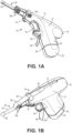
- FIGS. 1-3 illustrate a powered driver 10 configured to insert an IO device, such as an IO needle set 160, at a desired insertion site adjacent to a bone and associated bone marrow.
- the driver 10 may include one or more of the present features.
- the driver 10 comprises a housing 12 having a distal end 14 and a proximal end 16.
- the proximal end 16 of the housing may include a sharps receptor 80 configured to receive a portion of the IO device, as will be discussed in greater detail below.
- the housing 12 defines a primary portion or barrel portion 13 extending between the distal end 14 and the proximal end 16, and a handle 20 extending laterally from the primary portion 13.
- the handle 20 may extend from the primary portion 13 at a non-parallel angle (e.g., between thirty degrees (30°) and sixty degrees (60°), and in some embodiments, up to, including, or greater than ninety degrees (90°)) relative to the longitudinal axis of the primary portion 13.
- the housing 12 and the handle 20 may have an optimal ergonomic form factor (i.e., resembling a pistol-grip in the illustrated embodiments).
- the handle 20 defines an elongated, hollow compartment sized to receive a removable power source 40, such as batteries as shown in FIG. 3 .
- the housing 12 may be formed from heavy-duty polymeric material, or other strong material.
- the housing 12 may be formed in two halves which are joined together to form a fluid tight seal with certain components of driver 10 disposed in the housing, as shown.
- two halves of the housing 12 may be glued, welded, snapped, secured with screw fasteners, or otherwise coupled together such that the housing generally cannot be reopened (e.g., to replace batteries) without damaging the housing.
- the driver 10 may be configured as a single-use driver to prevent a second activation for inserting a second IO device into a patient. Preventing re-use of the driver maintains efficacy and promotes patient safety.
- an end cap 22 is coupled to the handle 20 by a pair of frangible members 24, such as tabs.
- the frangible members 24 are configured to break or snap in response to a user twisting, rocking, or pulling the end cap 22 relative to the handle 20 with a sufficient amount of force.
- the user can manually break or snap the frangible members 24 by applying a sufficient amount of force to the end cap 22 via twisting, rocking, or pulling in order to breakaway the end cap 22 from the handle 20.
- the end cap 22 is not removable from the handle 20 without breaking the frangible members 24, and thus also damaging the end cap and/or the handle.
- the end cap 22 includes at least one internal protrusion or shelf 26 configured to support the batteries 40 within the hollow compartment of the handle 20.
- the driver 10 may be used as a single-use device, whereby after insertion of the IO device in a target site of a patient is completed, the user can manually break off the end cap 22 from the handle 20 to allow easy removal and safe disposal of the batteries 40.
- the driver 10 may be configured to allow removal of the batteries 40 by pressing the frangible tabs located on each side of the handle 20 until the tabs break, thus causing the end cap 22 to disconnect from the handle.
- removing the end cap from the handle causes the batteries to be released from driver, such as from the bottom of the handle, and can therefore render the driver inoperable for future use.
- the powered driver 10 further comprises a motor 30, a gearbox 32, and a driveshaft 34.
- the motor 30 is disposed within the housing 12, with the driveshaft 34 extending outwardly from the distal end 14 of the housing in a direction away from proximal end 16 of the housing, such that a distal end 36 of the driveshaft 34 is spaced apart from the distal end 14 of the housing.
- gearbox 32 is coupled to the motor 30 and to the driveshaft 34 such that activation of the motor will cause rotation of the driveshaft.
- the driver 10 also comprises a power source including at least one battery (e.g., two batteries 40, as shown) configured to power the motor 18 (e.g., through an electrical communication between the batteries 40 and the motor 18, for example, through electrical wiring, circuitry, and/or the like).
- the power source may be two 9-volt batteries which may be commercially available from a variety of suppliers and retail outlets.
- Other embodiments can include any suitable battery and/or combination of batteries that permit the function(s) described in this disclosure.
- the driver 10 further includes a trigger 18 configured to be squeezed or otherwise depressed with a user's finger during use to activate the motor 30.
- the trigger 18 may be integrally formed with the housing 12.
- the trigger 18 is configured to close the electrical circuit between the power source 40 and the motor 30 upon application of a threshold force on the trigger to move the trigger to an "on" or activated position.
- the trigger 18 is normally biased to an "off" or non-activated position in which the electrical circuit between the power source 40 and the motor 30 is open.
- a conductive biasing member 19, such as a leaf spring, may bias the trigger 18 to the off position, such that in the absence of the threshold force on the trigger, the electrical circuit between the power source 40 and the motor 30 remains open and the motor is therefore not activated.
- the motor 30, the gearbox 32, and the driveshaft 34 are coupled in fixed axial relation to each other within the housing 12 (e.g., along the longitudinal axis of the primary portion 13 of the housing).
- the housing 12 may include one or more internal tabs or portions 38 on which the motor 30 and the gearbox 32 are mounted or otherwise supported (e.g., the internal tabs or portions are configured to support the motor 30 and the gearbox 32 in coaxial alignment with each other and physically prevent axial or lateral movement thereof).
- Motors and gear assemblies satisfactory for use with a powered driver incorporating features of the present disclosure may be obtained from various vendors. Such motor and gear assemblies may be ordered as "sets" with one end of each motor securely attached to an adjacent end of an associated gear assembly.
- a driveshaft having various dimensions and/or configurations may extend from the gear assembly opposite from the motor.
- the gear assemblies may further be referred to as "reduction gears” or “planetary gears.”
- the dimensions and/or configurations of an associated housing may be modified to accommodate an associated motor and gear assembly.
- the motor may be configured to rotate at a satisfactory speed and a satisfactory torque such that the gearbox is omitted and the motor directly drives the driveshaft.
- the driver 10 may further comprise a slot 42 formed in the handle 20 of the housing 12.
- the slot 42 is configured to receive a portion of an electrical lockout or electrical interrupt 44 to prevent accidental activation of the driver 10 for increased safety when handling the driver 10, and also to permit ethylene oxide (EtO) sterilization.
- the slot 42 is sized and positioned to allow a portion of the electrical lockout 44 to be inserted into the housing 12 to prevent the electrical circuit from being closed, thereby preventing energizing the driver 10 when the trigger 18 is pressed (e.g., to prevent activation of the driver during sterilization, packaging, transportation, or the like).
- the slot 42 may be located in the housing 12 closer to the primary portion 13 of the housing and still physically prevent the electrical circuit from being closed when the trigger 18 is pressed to avoid accidental activation of the motor.
- the electrical lockout 44 is configured to increase safety when handling the driver 10, such as during transportation or sterilization.
- the electrical lockout 44 comprises a flexible strip 46 that is removably inserted into the slot 42 in the handle 20 of the housing 12 between two electrically conductive portions of the electrical circuit to prevent the driver 10 from energizing during sterilization.
- the flexible strip 46 may comprise a polymer, such as Mylar, and/or other non-conductive material.
- the strip 46 of the electrical lockout 44 can be removed from the handle in a single pull in order to allow an electrical connection between the motor 30 and the power source 40 when the trigger 18 is pressed.
- distal end 14 of the housing 12 includes an opening 15 with a portion of the driveshaft 34 extending therethrough.
- the driveshaft 34 may include an annular groove 35 configured to receive an O-ring (e.g., a resilient polymeric or rubber O-ring) disposed around the driveshaft 34 and between the gearbox 32 and the distal end 14 of the housing 12 to seal the opening 15.
- O-ring e.g., a resilient polymeric or rubber O-ring
- at least a portion (e.g., distal end 36) of the driveshaft 34 has an equilateral polygonal cross-sectional shape.
- a portion of the driveshaft terminating in the distal end 36 has a pentagonal cross-sectional shape defined by five surfaces 37.
- the surfaces 37 may be tapered and/or disposed at an angle relative to the longitudinal axis of the driveshaft 34 (e.g., an angle of three degrees (3°) ⁇ two degrees (2°) relative to the longitudinal axis).
- a magnet can be disposed on and/or in the distal end 36 of the driveshaft 34 (e.g., or the distal end of the driveshaft may otherwise be magnetic). Fittings and/or connectors with various dimensions and/or configurations other than the depicted configuration of distal end 36 of the driveshaft may also be used with the powered driver 10 of the present disclosure.
- the distal end 36 of the driveshaft 34 may be configured to releasably secure an IO needle set 160.
- driveshaft 34 may be configured to releasably secure other IO needle sets and may comprise additional associated structure.
- Intraosseous (IO) devices having corresponding tapered openings or connector receptacles may be releasably engaged with the distal end 36 of the driveshaft 34.
- the distal end 36 may be releasably engaged with a tapered opening (e.g., 186) in a connector (e.g., 180) as illustrated in FIGS. 4A and 4B , which depict an example of an IO device or penetrator assembly 160 that is usable with the driver 10 of the present disclosure.
- the penetrator assembly 160 may include a connector 180, an associated hub 200, an outer penetrator 210, and an inner penetrator 220.
- the penetrator assembly 160 may include an outer penetrator such as a cannula, a hollow tube or hollow drill bit, and an inner penetrator such as a stylet or trocar.
- an outer penetrator or cannula 210 may be described as a generally elongated tube sized to receive an inner penetrator or stylet 220 therein. Portions of inner penetrator 220 may be disposed within a longitudinal passageway 184 extending through outer penetrator 210.
- the outside diameter of the inner penetrator 220 and the inside diameter of the longitudinal passageway 184 may be selected such that the inner penetrator 220 may be slidably disposed within the outer penetrator 210. It should be appreciated that the present disclosure is not limited to the connector 180 or the hub 200 shown in FIGS. 4A and 4B , which are representative of a variety of devices and components that can be used with embodiments of the present drivers and kits.
- a metallic disc 170 may be disposed within the opening 186 for use in releasably attaching the connector 180 with a magnet disposed on the distal end 36 of driveshaft 34 (e.g., or an otherwise magnetic driveshaft 34).
- An end 223 of the inner penetrator 220 may be spaced from the metallic disc 170 with insulating or electrically nonconductive material disposed therebetween.
- the metallic disc 170 may be magnetic and the drive shaft 34 and/or its distal end 36 may comprise metallic materials configured to releasably attach to the magnetic metallic disc of the connector 180.
- a tip 211 of the outer penetrator 210 and/or a tip 222 of the inner penetrator 220 may be operable to penetrate bone and associated bone marrow.
- the configuration of the tips 211 and/or 222 may be selected to penetrate a bone or other body cavities with minimal trauma.
- a first end or tip 222 of the inner penetrator 220 may be trapezoid-shaped and may include one or more cutting surfaces.
- outer penetrator 210 and inner penetrator 220 may be ground together as one unit during an associated manufacturing process.
- the outer penetrator 210 and/or the inner penetrator 220 may be formed from stainless steel, titanium, and/or other materials of suitable strength and durability to penetrate bone.
- the hub 200 may be used to stabilize penetrator assembly 160 during insertion of an associated penetrator into a patient's skin, soft tissue, and adjacent bone at a selected insertion site.
- a first end 201 of the hub 200 may be operable for releasable engagement or attachment with the associated connector 180.
- a second end 202 of the hub 200 may have a size and configuration compatible with an associated insertion site for outer penetrator 210.
- the combination of the hub 200 with the outer penetrator 210 may sometimes be referred to as a "penetrator set” or "intraosseous needle.”
- the connector 180 and the attached inner penetrator 220 may be releasably engaged with each other by Luer type fittings, threaded connections, and/or other suitable fittings formed on the first end 201 of the hub 200.
- the outer penetrator 210 extends from the second end 202 of the hub 200.
- the connector 180 may include a generally cylindrical tube defined in part by a first end 181 and a second end 182.
- the exterior of the connector 180 may include an enlarged tapered portion adjacent to the first end 181.
- a plurality of longitudinal ridges 190 may be formed on the exterior of the connector 180 in order to allow an operator to grasp the associated penetrator assembly 160 during attachment with the driveshaft 34. Longitudinal ridges 190 also allow the connector 180 to be grasped for disengagement from the hub 200 when the outer penetrator 210 has been inserted into a bone and associated bone marrow.
- the second end 182 of the connector 180 may include an opening 185 sized to receive the first end 201 of the hub 200 therein.
- Threads 188 may be formed in the opening 185 adjacent to the second end 182 of the connector 180.
- the threads 188 may be used to releasably attach the connector 180 with a threaded fitting 208 adjacent to the first end 201 of the hub 200.
- the first end 201 of the hub 200 may include a threaded connector 208 and/or other suitable fittings formed on the exterior thereof.
- the first end 201 may have a generally cylindrical pin-type configuration compatible to releasably engage the second end or box end 182 of the connector 180.
- the end 202 of the hub 200 may include a flange and an angular slot or groove 204 sized to receive one end of a protective cover or needle cap.
- the penetrator assembly may include only a single, hollow penetrator.
- the penetrator assembly may include an outer penetrator such as a cannula, a hollow needle or hollow drill bit, and an inner penetrator such as a stylet, trocar or other removable device disposed within the outer penetrator.
- Penetrator 210 is one example of a single, hollow penetrator or cannula.
- the size of the penetrator may vary depending on the intended application for the associated penetrator assembly. Penetrators may be relatively small for pediatric patients, medium size for adults, and large for oversize adults. By way of example, a penetrator may range in length from five (5) mm to thirty (30) mm.
- the diameter of a penetrator may range from eighteen (18) gauge to ten (10) gauge.
- the length and diameter of the penetrator used in a particular application may depend on the size of a bone to which the apparatus may be applied.
- Penetrators may be provided in a wide variety of configurations depending upon intended clinical purposes for insertion of the associated penetrator. For example, there may be one configuration for administering drugs and/or fluids to a patient's bone marrow and an alternative configuration for sampling bone marrow and/or blood from a patient. Other configurations may be appropriate for bone and/or tissue biopsy.
- the connector 180 may have a generally cylindrical configuration defined in part by the first end 181 and the second end 182. Exterior portions of the connector 180 may include an enlarged tapered portion adjacent to the first end 181. A plurality of longitudinal ridges 190 may be formed on the exterior of the connector 180 to allow an operator to grasp the associated penetrator assembly 160 during attachment with a driveshaft 34. Longitudinal ridges 190 also allow the connector 180 to be grasped for disengagement from the hub 200 when the outer penetrator 210 has been inserted into a bone and associated bone marrow. A first end 181 of the connector 180 may include an opening 186 sized to receive portions the driveshaft 32 therein.
- a plurality of webs 136 may extend radially outward from the connector receptacle 186.
- the webs 136 may cooperate with each other to form a plurality of openings 138 adjacent to the first end 181. Opening 186 and the plurality of openings 138 may cooperate with each other to form portions of a connector receptacle operable to receive respective portions of a connector therein.
- Embodiments of an intraosseous kit may include the powered driver 10 and the IO device (e.g., needle set 160) of the present disclosure.
- the components of the kit may be sterile and come ready to use with the IO needle set 160 already coupled to the driveshaft 32 of the driver 10 so that a user can quickly use the driver to insert the IO device into a target site of a patient shortly after opening the kit.
- Providing the driver 10 pre-loaded with the IO needle set 160 minimizes the IO procedure steps.
- An elongated guard member 50 may be connected to the distal end 14 of the housing 12.
- the guard member 50 is configured to cover the IO needle set 160 when the driver 10 is not in use in order to prevent accidental injury to a user, as well as to protect the components of the IO device from being damaged when not in use.
- the guard member 50 may include a needle section 52, a hub section 54, and a connector section 56, each of which are configured to correspondingly cover the respective needle 210/220, the hub 200, and the connector 180 of the IO needle set 160.
- a bottom surface of the guard member 50 may be concave in order to closely conform to the contours of the IO device.
- a distal tip 58 of the guard member 50 may have a smooth, bulbous non-cutting surface in order to prevent injury due to accidental contact with a user.
- a proximal end of the guard member 50 may include a first pivot part 51 pivotably attached to a second pivot part 17 provided on the distal end 14 of the housing 12, so that the guard member can be quickly switched between a protective position as shown in FIGS. 5A-5B and a non-protective position as shown in FIGS. 7A-7B .
- the needle section 52 of the guard member 50 further comprises a needle groove 53 for receiving the needle portion of the IO device when the guard member is in the protective position (e.g., the needle section 52 is disposed over the cannula 210 and the stylet 220 such that the needle groove 53 receives the cannula and the stylet).
- a retention collar 60 is provided inside the distal end 14 of the housing 12 and surrounds a portion of the driveshaft 34 to define an annular gap between the retention collar and the driveshaft.
- the retention collar 60 includes a pair of retention tabs 65 extending therefrom.
- the pair of retention tabs 65 are configured to engage a corresponding pair of locking notches 55 extending from the first pivot part 51 of the guard member 50 when the retention collar 60 and the driveshaft 34 are axially aligned in order to lock the guard member in the protective position, as shown in FIGS. 5A-5B and 8 .
- the guard member 50 is biased toward the non-protective position by a biasing element 70, such as a torsion spring, provided at the distal end 14 of the housing 12.
- the retention collar 60 is configured to move laterally relative to the driveshaft 34 when a release button 66 extending from the retention collar is pressed.
- the retention collar 60 may comprise a pair of release buttons 66, wherein each button of the pair of release buttons extends from opposing ends of the retention collar for ambidextrous use (e.g., so that each of the release buttons are accessible from opposing lateral sides of the housing 12 of the driver 10).
- the retention collar 60, the retention tabs 65 and the pair of release buttons 66 may be integrally formed as a single piece.
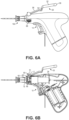
- a user can quickly switch the guard member 50 from its protective position shown in FIGS. 5A-5B to its non-protective position shown in FIGS. 7A-7B , by pressing either of the release buttons 66 to laterally move the retention collar 60 relative to the driveshaft 34.
- This movement disengages the retention tabs 65 of the collar from the locking notches 55 of the guard member 50, and thus correspondingly causes the biasing element 70 to urge the guard member to rotate about the first 51 and second 17 pivot parts.
- the ambidextrous release button 66 is activated, the retention tabs 65 connected to the collar 60 slide out of contact with the corresponding locking notches 55 of the guard member 50.
- This activation causes the torsion spring 70 to twist, which allows the guard member 50 to flip back to align with the primary portion 13 of the housing 12.
- the guard member is oriented in this non-protective position, the pre-loaded IO needle set 160 is exposed in preparation for an IO insertion.
- the guard member is depicted in an intermediate position (e.g., after a user presses the ambidextrous release button 66 to disengage the retention tabs 65 from the locking notches 55 so that the biasing element 70 can begin to rotate the guard member away from its protective position and toward its non-protective position).
- the guard member can be received in a corresponding guard recess 28 provided along a top surface of the housing 12.
- the guard recess 28 is shaped to fittingly receive each of the needle section 52, the hub section 54, the connector section 56, and the distal tip 58 of the guard member 50.
- the driver 10 and the IO needle set 160 can then be used at a desired insertion site on a patient. Operation of the driver 10 rotates the driveshaft 34 and the IO needle set 160 to puncture skin, soft tissue, and a layer of cortical bone at the insertion site.
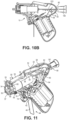
- the user can detach the connector 180 from the hub 200. Additional components, such an IV tubing and/or a syringe, can then be attached to the hub while it remains anchored to the insertion site. While the outer penetrator 210 of the hub 200 can remain inserted in the target site of the patient, the stylet 220 of the connector 180 can be inserted through the sharps receptor 80 and into the housing of the driver as illustrated in FIGS. 10-11 .
- the sharps receptor 80 defines an opening at the proximal end 16 of the housing 12.
- An interior support shelf 82 may be fixedly located within the proximal end 16 of the housing 12 and is configured to provide support to the portion of the IO device, such as the stylet 220, that is received within the housing.
- a flexible sharps guide 84 may also be located within the proximal end 16 of the housing 12 and is configured to guide the portion of the IO device, such as the stylet 220, as it is received into the housing.
- the flexible sharps guide 84 may be configured to bias the stylet 220 against the support shelf 82.
- the sharps guide 84 may be a leaf spring.
- the sharps guide 84 includes a guide slot 85 for receiving and guiding the stylet 220 as it is inserted into the housing.
- the interior support shelf 82 and the sharps guide 84 are both configured to securely retain the stylet within housing.
- the flexible sharps guide 84 may be biased toward a portion of the interior support shelf 82 so that the sharps guide correspondingly biases the stylet 220 against the support shelf as the stylet passes through the guide slot 85, thus retaining the stylet within the housing.
- the guide slot 85 is also configured to restrict lateral movement of the stylet 220.
- the user can remove the stylet 220 from the outer penetrator 210 and insert the sharp tip of the stylet 220 into the back of the housing 12 for safe disposal of the stylet with the single-use driver 10.
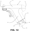
- FIGS. 12 and 13 illustrate another implementation of a driver housing 112 which is substantially similar to the driver housing 12 previously described, with the exception of certain features described as follows.
- the housing 112 defines a primary portion or barrel portion 113 extending between a distal end 114 and the proximal end 116, and a handle 120 extending laterally from the primary portion 113.
- the handle 120 may extend from the primary portion 113 at a non-parallel angle (e.g., between thirty degrees (30°) and sixty degrees (60°), and in some embodiments, up to, including, or greater than ninety degrees (90°)) relative to the longitudinal axis of the primary portion 113.
- a non-parallel angle e.g., between thirty degrees (30°) and sixty degrees (60°)
- 90° ninety degrees
- the housing 112 and the handle 120 may have an ergonomic form factor (i.e., resembling a pistol-grip in the illustrated embodiments).
- the handle 120 defines an elongated, hollow compartment sized to receive a removable power source, such as batteries.
- the housing 112 may be formed from heavy-duty polymeric material, or other strong material.
- the housing 112 may be formed in two halves which are joined together to form a fluid tight seal with various components of the driver disposed therein.
- two halves of the housing 112 may be glued, welded, snapped, secured with screw fasteners, or otherwise coupled together such that the housing generally cannot be reopened (e.g., to replace batteries) without damaging the housing.
- the driver may be configured as a single-use driver to prevent a second activation for inserting a second IO device into a patient. Preventing re-use of the driver maintains efficacy and promotes patient safety.
- an end cap 122 is coupled to the handle 120 by at least one frangible member 124, such as a breakaway tab.
- Each breakaway tab 124 may be disposed on an outer periphery of the end cap 122.
- Each breakaway tab 124 is configured to break or snap in response to a user pulling the end cap 122 relative to the handle 120 with a sufficient amount of force.
- the end cap 122 further includes a grip portion 128 defining a recess sized and shaped to receive a user's thumb or other finger so that the user can laterally grip the end cap 122 in order to allow the user to rotate the end cap relative to the handle 120 to break the at least one frangible member 124, and therefore remove the end cap from the handle so that the batteries within the handle can be disposed of.
- the user can manually break or snap the frangible members 124 by applying a sufficient amount of force to the end cap 122 via gripping the grip portion and pulling or rotating the end cap relative to the handle 120 in order to breakaway the end cap from the handle.
- the end cap 122 is not removable from the handle 120 without breaking the at least one frangible members 124.
- the end cap 122 includes at least one internal protrusion or shelf 126 configured to support batteries within the hollow compartment of the handle 120.
- the driver may be used as a single-use device, whereby after insertion of the IO device in a target site of a patient is completed, the user can manually break off the end cap 122 from the handle 120 to allow easy removal and safe disposal of the batteries.
Description
- The present disclosure is generally related to powered drivers for inserting an intraosseous device into a patient's bone, and more particularly, but not by way of limitation, to single-use powered drivers having a protective member for the intraosseous device.
- Many patients require direct vascular access for the treatment of certain medical conditions or life -threatening emergencies, such as shock, trauma, cardiac arrest, drug overdoses, diabetic ketoacidosis, arrhythmias, burns, and status epilepticus, just to name a few. An essential element for treating medical emergencies is rapid establishment of an intravenous (IV) line to administer drugs and fluids directly into the circulatory system. However, some patients may experience problems with traditional intravenous access. Obtaining satisfactory vascular access can therefore be a critical problem for some patients treated in either pre-hospital or hospital settings. For instance, doctors, nurses and paramedics may experience great difficulty establishing IV access in some patients. These patients are probed repeatedly with sharp needles in an attempt to solve this problem and may require an invasive procedure to finally establish an intravenous route. A further complicating factor in achieving IV access occurs "in the field," e.g., at the scene of an accident or during ambulance transport where it is difficult to see the target site and excessive motion can make accessing the venous system very difficult.
- In the case of patients with chronic disease, or elderly patients, the availability of easily-accessible veins may be depleted. Other patients may have no available IV sites due to anatomical scarcity of peripheral veins, obesity, extreme dehydration or previous IV drug use. For these patients, finding a suitable site for administering lifesaving drugs becomes a monumental and frustrating task. Patients with life -threatening emergencies risk death from ensuing complications when access to the vascular system with life-saving IV therapy is delayed or simply not possible. For such patients, an alternative approach utilizing intraosseous (10) access can help. Such IO access may be achieved by using powered drivers associated with IO devices.
- Conventional powered drivers typically include a housing with various types of motors and/or gear assemblies disposed therein. Many powered drivers, however, must be manually loaded prior to use, and are also intended to be reusable for many applications. Therefore, there is a need for a powered driver having a pre-loaded IO device, such as an IO needle assembly, that is releasably attached thereto for rapid insertion of the IO device into a target site of a patient. There is a further need for a protective cover for the pre-loaded IO device to prevent damage to the IO device and to prevent accidental harm to a user. There is also a need for a single-use powered driver for preventing a user from re-using the driver after insertion of the IO device into an insertion site.
-
WO2015/123660 discloses powered drivers for the insertion of intraosseous needs into a patient's bone. A needle cap may be provided over the needle which is removed prior to use. - Embodiments of the present drivers and kits can be configured to assist a user with inserting an intraosseous (10) device into a patient's bone.
- The present invention is directed to a driver for inserting an intraosseous needle assembly into a bone and associated bone marrow, the driver comprising a housing having a distal end and a proximal end; a motor disposed in the housing; a driveshaft extending outward from the distal end of the housing in a direction away from the proximal end; a gearbox coupled to the motor and to the driveshaft such that activation of the motor causes the driveshaft to rotate; a power source configured to power the motor; a guard member pivotably connected to the housing and movable between a protective position and a non-protective position, wherein the guard member is configured to cover the intraosseous needle assembly in the protective position and to expose the intraosseous needle assembly in the non- protective position; and a biasing member configured to urge the guard member toward the non-protective position.
- In some embodiments of the present invention, the guard member is pivotably connected to the distal end of the housing.
- In some embodiments of the present invention, the biasing member is a torsion spring.
- In some embodiments of the present invention, a proximal end of the guard member includes a first pivot part, and a distal end of the housing includes a second pivot part, wherein the first and second pivot parts are configured to engage each other to allow the guard member to pivot relative to the housing.
- Some embodiments of the present invention further comprise a generally cylindrical retention collar provided within the distal end of the housing and surrounding the driveshaft to define an annular gap therebetween, and wherein an axis of the retention collar is substantially aligned with an axis of the driveshaft when the guard member is oriented in the protective position.
- Some embodiments of the present invention further comprise a pair of locking notches extending from the first pivot part of the guard member, and a pair of corresponding retention tabs extending upwardly from the collar, wherein the pair of locking notches are configured to engage the pair of retention tabs when the guard member is oriented in the protective position.
- Some embodiments of the present invention further comprise a pair of oppositely spaced apart release buttons extending from opposed ends of the retention collar, wherein activating the pair of release buttons moves the retention collar laterally relative to the driveshaft to disengage the pair of retention tabs from contacting the corresponding pair of locking notches, thereby allowing the biasing member to pivot the guard member from the protective position to the non-protective position.
- In some embodiments of the present invention, the guard member comprises a needle groove configured to receive an intraosseous needle.
- In some embodiments of the present invention, the guard member comprises a distal tip having a smooth bulbous shape.
- Some embodiments of the present invention further comprise a sharps receptor defining an opening provided in the proximal end of the housing and configured to receive an intraosseous needle.
- Some implementations of the present disclosure further comprise a flexible sharps guide and an interior support shelf the sharps guide being located within the proximal end of the housing and configured to guide the intraosseous needle as it is received into the housing, and the interior support shelf being located within the proximal end of the housing and configured to support the intraosseous needle as it is received into the housing.
- In some implementations of the present disclosure, the sharps guide comprises a guide slot for receiving and guiding the intraosseous needle as it is inserted into the housing, and wherein the interior support shelf and the sharps guide are both configured to securely retain the intraosseous needle within the housing such that the sharps guide is biased toward the interior support shelf.
- In some implementations of the present disclosure, the sharps guide is a leaf spring.
- Some implementations of the present disclosure further comprise a trigger configured to close an electrical circuit between the power source and the motor upon activation of the trigger in order to rotate the driveshaft.
- In some embodiments of the present invention, the housing defines a primary portion extending between the distal end and the proximal end, and a handle extending laterally from the primary portion at a non-parallel angle relative to a longitudinal axis of the primary portion.
- In some embodiments of the present invention, the handle defines a hollow compartment for storing the power source.
- Some embodiments of the present invention further comprise an end cap connected to the handle by at least one frangible member configured to break or snap upon application of a threshold force to cause the end cap to detach from the handle, and thereby cause the power source to fall out from the compartment of the handle.
- In embodiments of the present invention, the end cap further includes a grip portion defining a recess sized and shaped for receiving a user's thumb or other finger so that the user can laterally grip the end cap in order to facilitate pulling or rotating the end cap relative to the handle to break the at least one frangible member.
- In some implementations of the present disclosure, the power source comprises at least one battery.
- In some implementations of the present disclosure, at least a portion of the driveshaft has an equilateral polygonal cross-sectional shape.
- In some implementations of the present disclosure, the at least a portion of the driveshaft has a pentagonal cross-sectional shape.
- In some embodiments of the present invention, a top surface of the handle comprises a guard recess having a shape corresponding to the shape of the guard member for receiving the guard member when in the non-protective position.
- Some implementations of the present disclosure further comprise an electrical lockout comprising a strip configured to be removably inserted into the housing between two electrically conductive portions of the electrical circuit to prevent the apparatus from energizing during sterilizing or transporting.
- In some implementations of the present disclosure, the strip comprises a polymer. In some implementations of the present disclosure, the polymer comprises Mylar.
- Some embodiments of the present disclosure are directed toward a kit comprising the driver discussed above and an intraosseous device comprising a connector be coupled to the driveshaft of the driver; and wherein the guard member of the driver is oriented in a protective position.
- In some implementations of the present disclosure, the connector comprises a recess configured to receive a distal end of the driveshaft.
- In some implementations of the present disclosure, the intraosseous device comprises: a hub; a cannula extending from the hub to a distal end spaced from the hub; a trocar extending from the connector to a distal end spaced from the connector; and wherein the cannula is configured to be inserted into the cannula and the connector coupled to the hub to hold the trocar in fixed relation to the cannula.
- In some implementations of the present disclosure, the connector is configured to be coupled to the hub by a Luer lock connector.
- In some implementations of the present disclosure, the connector comprises a female threaded portion surrounding a portion of the trocar, the hub comprises a male threaded portion extending away from the distal end of the cannula, and the male threaded portion is configured to be coupled to the female threaded portion to couple the connector to the hub.
- The term "substantially" is defined as largely but not necessarily wholly what is specified (and includes what is specified; e.g., substantially 90 degrees includes 90 degrees and substantially parallel includes parallel), as understood by a person of ordinary skill in the art. In any disclosed embodiment, the terms "substantially," "approximately," and "about" may be substituted with "within [a percentage] of" what is specified, where the percentage includes .1, 1, 5, and 10 percent. Further, a device or system that is configured in a certain way is configured in at least that way, but it can also be configured in other ways than those specifically described.
- The feature or features of one embodiment may be applied to other embodiments, even though not described or illustrated, unless expressly prohibited by this disclosure or the nature of the embodiments. Some details associated with the embodiments described above and others are described below.
- The following drawings illustrate embodiments of the disclosure by way of example and not limitation. For the sake of brevity and clarity, every feature of a given structure is not always labeled in every figure in which that structure appears. Identical reference numbers do not necessarily indicate an identical structure. Rather, the same reference number may be used to indicate a similar feature or a feature with similar functionality, as may non-identical reference numbers. The embodiments of the present drivers and intraosseous (IO) devices, and their components shown in the figures, are not necessarily drawn to scale.
-
FIGS. 1A and 1B depict respective bottom and top isometric views of an embodiment of the driver assembly and the intraosseous device of the present disclosure. -
FIG. 2A depicts a top plan view of the driver assembly and the intraosseous device of the present disclosure. -
FIGS. 2B and2C depict a front elevation view and a rear elevation view, respectively, of the driver assembly and the intraosseous device of the present disclosure. -
FIG. 3 depicts a partial cross-sectional perspective view of the driver assembly and the intraosseous device of the present disclosure. -
FIG. 4A depicts an exploded and partially cutaway side view of one example of an intraosseous device, such as an intraosseous needle set or penetrator assembly which may be inserted into a patient's bone and, thus, into a patient's vascular system using one of the present drivers and may be included in certain ones of the present kits. -
FIG. 4B depicts a partial perspective view of a connector receptacle of the IO needle set ofFIG. 4A that may be releasably engaged with embodiments of the present powered drivers. -
FIG. 5A illustrates a side elevation view of the driver assembly and the intraosseous device of the present disclosure with a needle guard in a protective position over the IO needle set ofFIGS. 4A-4B coupled to a driveshaft of the driver. -
FIG. 5B illustrates a partial cross-sectional side view of the driver assembly of the present disclosure with a needle guard in a protective position over the IO needle set ofFIGS. 4A-4B coupled to a driveshaft of the driver. -
FIG. 6A illustrates a side elevation view of the driver assembly of the present disclosure with a needle guard in an intermediate position and with the IO needle set ofFIGS. 4A-4B coupled to a driveshaft of the driver. -
FIG. 6B illustrates a partial cross-sectional side view of the driver assembly of the present disclosure with a needle guard in an intermediate position and with the IO needle set ofFIGS. 4A-4B coupled to a driveshaft of the driver. -
FIG. 7A illustrates a side elevation view of the driver assembly of the present disclosure with a needle guard in a non-protective position with respect to the IO needle set ofFIGS. 4A-4B coupled to a driveshaft of the driver. -
FIG. 7B illustrates a partial cross-sectional side view of the driver assembly of the present disclosure with a needle guard in a non-protective position with respect to the IO needle set ofFIGS. 4A-4B coupled to a driveshaft of the driver. -
FIG. 8 illustrates a close-up isometric view of a part of the driver assembly and the IO needle set of the present disclosure with the needle guard in the protective position. -
FIGS. 9A and9B illustrate different close-up views of a part of the driver assembly of the present disclosure with a transparent view of the needle guard in the non-protective position. -
FIG. 10A depicts a side elevation view of the present driver with a needle guard in the non-protective position and with a connector of the IO needle set ofFIGS. 4A-4B coupled to a sharps receptor of the driver. -
FIG. 10B depicts a partial cross-sectional side view of the present driver with a needle guard in the non-protective position and with a connector of the IO needle set ofFIGS. 4A-4B coupled to a sharps receptor of the driver. -
FIG. 11 depicts a perspective view of the driver ofFIG. 10B with a needle guard in the non-protective position and with a connector of the IO needle set ofFIGS. 4A-4B coupled to a sharps receptor of the driver. -
FIG. 12 depicts a side elevation view of another implementation of a driver housing having a handle with a breakable end cap. -
FIG. 13 illustrates a cross-sectional view of the housing shown inFIG. 12 . - Vascular system access may be essential for treatment of many serious diseases, chronic conditions, and acute emergency situations. Yet, many patients experience extreme difficulty obtaining effective treatment because of an inability to obtain or maintain intravenous (IV) access. An intraosseous (IO) space provides a direct conduit to a patent's vascular system and systemic circulation. Therefore, IO access is generally an effective route to administer a wide variety of drugs, other medications, and/or IV fluids. Moreover, rapid IO access or emergency vascular access (EVA) offers great promise for a wide range of serious emergencies that require vascular access to administer life-saving drugs, other medications, and/or fluids when traditional IV access is difficult or impossible.
- Bone marrow typically includes blood, blood forming cells, and connective tissue disposed in an intraosseous space or cavity surrounded by compact bone. Long bones such as the tibia typically have an elongated central cavity filled with yellow bone marrow and adipose or connective tissue. Such cavities may also be referred to as a "medullary cavity," "bone marrow cavity," and/or "intraosseous space." Compact bone disposed near an anterior or dorsal surface may be referred to as "anterior compact bone" or "anterior bone cortex." Compact bone disposed farther from the dorsal or anterior surface may be referred to as "posterior compact bone" or "posterior bone cortex." Embodiments of the present powered drivers may be used to insert an IO device incorporating teachings of the present disclosure into a selected target area or target site (e.g., in ten seconds or less).
- Examples of insertion sites for an IO device to establish access with a patient's vascular system include the upper tibia proximate a patient's knee, the lower tibia, the humeral head proximate a patient's shoulder, and the patient's sternum. Other desired insertion sites may be disposed over a distal portion of the patient's femur, a patient's clavicle, a patient's iliac crest, or a patient's calcaneous. Availability of multiple intraosseous insertion sites and associated target areas in adjacent bone marrow have proven to be particularly important in applications such as emergency treatment of battlefield casualties or other mass casualty situations. Teachings of the present disclosure may be used to obtain intraosseous access at a wide variety of insertion sites and target areas.
- IO access may be used as a "bridge" for temporary fluid and/or drug therapy during emergency conditions until conventional IV sites can be found and used. Conventional IV sites often become available because fluids and/or medication provided via IO access may stabilize a patient and expand veins and other portions of a patient's vascular system. IO devices and associated procedures incorporating teachings of the present disclosure may become standard care for administering medications and fluids in situations when IV access is difficult or otherwise impossible.
- Intraosseous access may be used as a "routine" procedure with chronic conditions which substantially reduce or eliminate availability of conventional IV sites. Examples of such chronic conditions may include, but are not limited to, dialysis patients, patients in intensive care units, and/or epilepsy patients. Intraosseous devices and associated apparatuses incorporating teachings of the present disclosure may be quickly and safely used to provide IO access to a patient's vascular system in difficult cases, such as status epilepticus, to give medical personnel an opportunity to administer crucial medications and/or fluids. Further examples of such acute and chronic conditions are listed near the end of this written description.
- Apparatuses and methods incorporating teachings of the present disclosure may include using a first IO needle set having a (e.g., a fifteen (15) gauge) cannula with a length of approximately fifteen (15) millimeters to establish vascular access for patients weighing between approximately three (3) kilograms and thirty nine (39) kilograms. A second IO needle set having a (e.g., a fifteen (15) gauge) cannula with an approximate length of twenty-five (25) millimeters may be used to establish vascular access for patients weighing forty (40) kilograms and greater. In other embodiments, a single size of IO needle set having a (e.g., a fifteen (15) gauge) cannula with an approximate length of twenty-five (25) millimeters may be used to establish vascular access for patients weighing three (3) kilograms and greater.
- The term "driver" may be used in this application to include any type of powered driver satisfactory for inserting an intraosseous (IO) device such as a penetrator assembly, a catheter, an IO needle, and/or an IO needle set into a selected portion of a patient's vascular system. Various techniques may be satisfactorily used to releasably engage or attach an IO device with a driver incorporating teachings of the present disclosure. A wide variety of connectors and associated connector receptacles, fittings, and/or other types of connections with various dimensions and configurations may be satisfactorily used to releasably engage an IO device with a driver. A battery powered driver incorporating teachings of the present disclosure may be used to insert an intraosseous device into a selected target area in ten (10) seconds or less. The reduced size and weight of drivers incorporating teachings of the present disclosure may accommodate use in emergency medical vehicles, in emergency crash carts at medical facilities, and/or in carrying inside backpacks of military personnel deployed for extended periods of time in remote locations.
- The term "fluid" may be used in this application to include liquids such as, but not limited to, blood, water, saline solutions, IV solutions, plasma, any mixture of liquids, particulate matter, dissolved medication, and/or drugs associated with biopsy and/or aspiration of bone marrow, and/or communication of fluids with bone marrow or other target sites. The term "fluid" may also be used in this application to include any body fluids and/or liquids containing particulate matter such as bone marrow and/or cells which may be withdrawn from a target area.
- The term "insertion site" may be used in this application to describe a location on a bone at which an intraosseous device may be inserted or drilled into the bone and associated bone marrow. Insertion sites are generally covered by skin and soft tissue. The term "target area" refers to any location on or within biological material, such as the biological material of a human being.
- The term "intraosseous (IO) device" may be used in this application to include, but is not limited to, any hollow needle, hollow drill bit, penetrator assembly, bone penetrator, catheter, cannula, trocar, stylet, inner penetrator, outer penetrator, IO needle, biopsy needle, aspiration needle, IO needle set, biopsy needle set, and/or aspiration needle set operable to access or provide access to an intraosseous space or interior portions of a bone. Such IO devices may be formed, at least in part, from metal alloys such as 304 stainless steel and/or other biocompatible materials associated with needles and similar medical devices.
- For some applications an IO needle or IO needle set may include a connector with a trocar or stylet extending from a first end of the connector. A second end of the connector may be operable to be releasably engaged with a powered driver incorporating teachings of the present disclosure. An IO needle or IO needle set may also include a hub with a hollow cannula or catheter extending from a first end of the hub. A second end of the hub may include an opening sized to allow inserting the trocar through the opening and the attached hollow cannula. The second end of the hub may be operable to be releasably engaged with the first end of the connector. As previously noted, the second end of the connector may be releasably engaged with a powered driver. A wide variety of connectors and hubs may be used with an IO device incorporating teachings of the present disclosure.
-
FIGS. 1-3 illustrate apowered driver 10 configured to insert an IO device, such as an IO needle set 160, at a desired insertion site adjacent to a bone and associated bone marrow. Thedriver 10 may include one or more of the present features. Thedriver 10 comprises ahousing 12 having adistal end 14 and aproximal end 16. Theproximal end 16 of the housing may include asharps receptor 80 configured to receive a portion of the IO device, as will be discussed in greater detail below. Thehousing 12 defines a primary portion orbarrel portion 13 extending between thedistal end 14 and theproximal end 16, and ahandle 20 extending laterally from theprimary portion 13. Thehandle 20 may extend from theprimary portion 13 at a non-parallel angle (e.g., between thirty degrees (30°) and sixty degrees (60°), and in some embodiments, up to, including, or greater than ninety degrees (90°)) relative to the longitudinal axis of theprimary portion 13. In some implementations, thehousing 12 and thehandle 20 may have an optimal ergonomic form factor (i.e., resembling a pistol-grip in the illustrated embodiments). Thehandle 20 defines an elongated, hollow compartment sized to receive aremovable power source 40, such as batteries as shown inFIG. 3 . Thehousing 12 may be formed from heavy-duty polymeric material, or other strong material. For some applications, thehousing 12 may be formed in two halves which are joined together to form a fluid tight seal with certain components ofdriver 10 disposed in the housing, as shown. For example, two halves of thehousing 12 may be glued, welded, snapped, secured with screw fasteners, or otherwise coupled together such that the housing generally cannot be reopened (e.g., to replace batteries) without damaging the housing. - The
driver 10 may be configured as a single-use driver to prevent a second activation for inserting a second IO device into a patient. Preventing re-use of the driver maintains efficacy and promotes patient safety. In the embodiment shown, anend cap 22 is coupled to thehandle 20 by a pair offrangible members 24, such as tabs. Thefrangible members 24 are configured to break or snap in response to a user twisting, rocking, or pulling theend cap 22 relative to thehandle 20 with a sufficient amount of force. Thus, after a user completes successful insertion of an IO device into a target area of a patient, the user can manually break or snap thefrangible members 24 by applying a sufficient amount of force to theend cap 22 via twisting, rocking, or pulling in order to breakaway theend cap 22 from thehandle 20. Theend cap 22 is not removable from thehandle 20 without breaking thefrangible members 24, and thus also damaging the end cap and/or the handle. Theend cap 22 includes at least one internal protrusion orshelf 26 configured to support thebatteries 40 within the hollow compartment of thehandle 20. - Once the
frangible members 24 are broken and theend cap 22 is decoupled from thehandle 20, thebatteries 40 are no longer supported by theinternal protrusion 26 of theend cap 22, thus causing the batteries to fall out from the hollow compartment of the handle. Moreover, once thefrangible members 24 are snapped or broken, theend cap 22 can no longer be reconnected to thehandle 20 without the use of some supplemental bonding or fixing element, such as adhesive. Accordingly, thedriver 10 may be used as a single-use device, whereby after insertion of the IO device in a target site of a patient is completed, the user can manually break off theend cap 22 from thehandle 20 to allow easy removal and safe disposal of thebatteries 40. - According to other aspects of the disclosure, the
driver 10 may be configured to allow removal of thebatteries 40 by pressing the frangible tabs located on each side of thehandle 20 until the tabs break, thus causing theend cap 22 to disconnect from the handle. As previously explained, removing the end cap from the handle causes the batteries to be released from driver, such as from the bottom of the handle, and can therefore render the driver inoperable for future use. - As shown in
FIG. 3 , thepowered driver 10 further comprises amotor 30, agearbox 32, and adriveshaft 34. Themotor 30 is disposed within thehousing 12, with thedriveshaft 34 extending outwardly from thedistal end 14 of the housing in a direction away fromproximal end 16 of the housing, such that adistal end 36 of thedriveshaft 34 is spaced apart from thedistal end 14 of the housing. In the embodiment shown,gearbox 32 is coupled to themotor 30 and to thedriveshaft 34 such that activation of the motor will cause rotation of the driveshaft. In this embodiment, thedriver 10 also comprises a power source including at least one battery (e.g., twobatteries 40, as shown) configured to power the motor 18 (e.g., through an electrical communication between thebatteries 40 and themotor 18, for example, through electrical wiring, circuitry, and/or the like). In some implementations of thedriver 10, the power source may be two 9-volt batteries which may be commercially available from a variety of suppliers and retail outlets. Other embodiments can include any suitable battery and/or combination of batteries that permit the function(s) described in this disclosure. - In the depicted embodiment, the
driver 10 further includes atrigger 18 configured to be squeezed or otherwise depressed with a user's finger during use to activate themotor 30. Thetrigger 18 may be integrally formed with thehousing 12. In this embodiment, thetrigger 18 is configured to close the electrical circuit between thepower source 40 and themotor 30 upon application of a threshold force on the trigger to move the trigger to an "on" or activated position. Thetrigger 18 is normally biased to an "off" or non-activated position in which the electrical circuit between thepower source 40 and themotor 30 is open. A conductive biasingmember 19, such as a leaf spring, may bias thetrigger 18 to the off position, such that in the absence of the threshold force on the trigger, the electrical circuit between thepower source 40 and themotor 30 remains open and the motor is therefore not activated. - In this embodiment, the
motor 30, thegearbox 32, and thedriveshaft 34 are coupled in fixed axial relation to each other within the housing 12 (e.g., along the longitudinal axis of theprimary portion 13 of the housing). Additionally, thehousing 12 may include one or more internal tabs orportions 38 on which themotor 30 and thegearbox 32 are mounted or otherwise supported (e.g., the internal tabs or portions are configured to support themotor 30 and thegearbox 32 in coaxial alignment with each other and physically prevent axial or lateral movement thereof). Motors and gear assemblies satisfactory for use with a powered driver incorporating features of the present disclosure may be obtained from various vendors. Such motor and gear assemblies may be ordered as "sets" with one end of each motor securely attached to an adjacent end of an associated gear assembly. A driveshaft having various dimensions and/or configurations may extend from the gear assembly opposite from the motor. The gear assemblies may further be referred to as "reduction gears" or "planetary gears." The dimensions and/or configurations of an associated housing may be modified to accommodate an associated motor and gear assembly. In some embodiments, the motor may be configured to rotate at a satisfactory speed and a satisfactory torque such that the gearbox is omitted and the motor directly drives the driveshaft. - The
driver 10 may further comprise aslot 42 formed in thehandle 20 of thehousing 12. Theslot 42 is configured to receive a portion of an electrical lockout or electrical interrupt 44 to prevent accidental activation of thedriver 10 for increased safety when handling thedriver 10, and also to permit ethylene oxide (EtO) sterilization. Theslot 42 is sized and positioned to allow a portion of theelectrical lockout 44 to be inserted into thehousing 12 to prevent the electrical circuit from being closed, thereby preventing energizing thedriver 10 when thetrigger 18 is pressed (e.g., to prevent activation of the driver during sterilization, packaging, transportation, or the like). In other embodiments, theslot 42 may be located in thehousing 12 closer to theprimary portion 13 of the housing and still physically prevent the electrical circuit from being closed when thetrigger 18 is pressed to avoid accidental activation of the motor. - The
electrical lockout 44 is configured to increase safety when handling thedriver 10, such as during transportation or sterilization. Theelectrical lockout 44 comprises aflexible strip 46 that is removably inserted into theslot 42 in thehandle 20 of thehousing 12 between two electrically conductive portions of the electrical circuit to prevent thedriver 10 from energizing during sterilization. Theflexible strip 46 may comprise a polymer, such as Mylar, and/or other non-conductive material. Thestrip 46 of theelectrical lockout 44 can be removed from the handle in a single pull in order to allow an electrical connection between themotor 30 and thepower source 40 when thetrigger 18 is pressed. - In the embodiments shown,
distal end 14 of thehousing 12 includes anopening 15 with a portion of thedriveshaft 34 extending therethrough. Further, thedriveshaft 34 may include anannular groove 35 configured to receive an O-ring (e.g., a resilient polymeric or rubber O-ring) disposed around thedriveshaft 34 and between thegearbox 32 and thedistal end 14 of thehousing 12 to seal theopening 15. In some embodiments, at least a portion (e.g., distal end 36) of thedriveshaft 34 has an equilateral polygonal cross-sectional shape. For example, in the embodiment shown, a portion of the driveshaft terminating in thedistal end 36 has a pentagonal cross-sectional shape defined by fivesurfaces 37. In some embodiments, such as the one shown, thesurfaces 37 may be tapered and/or disposed at an angle relative to the longitudinal axis of the driveshaft 34 (e.g., an angle of three degrees (3°) ± two degrees (2°) relative to the longitudinal axis). In some embodiments, a magnet can be disposed on and/or in thedistal end 36 of the driveshaft 34 (e.g., or the distal end of the driveshaft may otherwise be magnetic). Fittings and/or connectors with various dimensions and/or configurations other than the depicted configuration ofdistal end 36 of the driveshaft may also be used with thepowered driver 10 of the present disclosure. For example, in the implementation shown, thedistal end 36 of thedriveshaft 34 may be configured to releasably secure an IO needle set 160. In other implementations,driveshaft 34 may be configured to releasably secure other IO needle sets and may comprise additional associated structure. - Intraosseous (IO) devices having corresponding tapered openings or connector receptacles may be releasably engaged with the
distal end 36 of thedriveshaft 34. For example, thedistal end 36 may be releasably engaged with a tapered opening (e.g., 186) in a connector (e.g., 180) as illustrated inFIGS. 4A and 4B , which depict an example of an IO device orpenetrator assembly 160 that is usable with thedriver 10 of the present disclosure. Thepenetrator assembly 160 may include aconnector 180, an associatedhub 200, anouter penetrator 210, and aninner penetrator 220. Thepenetrator assembly 160 may include an outer penetrator such as a cannula, a hollow tube or hollow drill bit, and an inner penetrator such as a stylet or trocar. Various types of stylets and/or trocars may be disposed within an outer penetrator. For some applications, an outer penetrator orcannula 210 may be described as a generally elongated tube sized to receive an inner penetrator orstylet 220 therein. Portions ofinner penetrator 220 may be disposed within alongitudinal passageway 184 extending throughouter penetrator 210. The outside diameter of theinner penetrator 220 and the inside diameter of thelongitudinal passageway 184 may be selected such that theinner penetrator 220 may be slidably disposed within theouter penetrator 210. It should be appreciated that the present disclosure is not limited to theconnector 180 or thehub 200 shown inFIGS. 4A and 4B , which are representative of a variety of devices and components that can be used with embodiments of the present drivers and kits. - A
metallic disc 170 may be disposed within theopening 186 for use in releasably attaching theconnector 180 with a magnet disposed on thedistal end 36 of driveshaft 34 (e.g., or an otherwise magnetic driveshaft 34). Anend 223 of theinner penetrator 220 may be spaced from themetallic disc 170 with insulating or electrically nonconductive material disposed therebetween. In some embodiments, themetallic disc 170 may be magnetic and thedrive shaft 34 and/or itsdistal end 36 may comprise metallic materials configured to releasably attach to the magnetic metallic disc of theconnector 180. - A
tip 211 of theouter penetrator 210 and/or atip 222 of theinner penetrator 220 may be operable to penetrate bone and associated bone marrow. The configuration of thetips 211 and/or 222 may be selected to penetrate a bone or other body cavities with minimal trauma. A first end or tip 222 of theinner penetrator 220 may be trapezoid-shaped and may include one or more cutting surfaces. In one embodiment,outer penetrator 210 andinner penetrator 220 may be ground together as one unit during an associated manufacturing process. Providing a matching fit allowsrespective tips penetrator assembly 160 are inserted into a bone and associated bone marrow. Theouter penetrator 210 and/or theinner penetrator 220 may be formed from stainless steel, titanium, and/or other materials of suitable strength and durability to penetrate bone. - The
hub 200 may be used to stabilizepenetrator assembly 160 during insertion of an associated penetrator into a patient's skin, soft tissue, and adjacent bone at a selected insertion site. Afirst end 201 of thehub 200 may be operable for releasable engagement or attachment with the associatedconnector 180. Asecond end 202 of thehub 200 may have a size and configuration compatible with an associated insertion site forouter penetrator 210. The combination of thehub 200 with theouter penetrator 210 may sometimes be referred to as a "penetrator set" or "intraosseous needle." Theconnector 180 and the attachedinner penetrator 220 may be releasably engaged with each other by Luer type fittings, threaded connections, and/or other suitable fittings formed on thefirst end 201 of thehub 200. Theouter penetrator 210 extends from thesecond end 202 of thehub 200. - In some implementations, the
connector 180 may include a generally cylindrical tube defined in part by afirst end 181 and asecond end 182. The exterior of theconnector 180 may include an enlarged tapered portion adjacent to thefirst end 181. A plurality oflongitudinal ridges 190 may be formed on the exterior of theconnector 180 in order to allow an operator to grasp the associatedpenetrator assembly 160 during attachment with thedriveshaft 34.Longitudinal ridges 190 also allow theconnector 180 to be grasped for disengagement from thehub 200 when theouter penetrator 210 has been inserted into a bone and associated bone marrow. Thesecond end 182 of theconnector 180 may include anopening 185 sized to receive thefirst end 201 of thehub 200 therein.Threads 188 may be formed in theopening 185 adjacent to thesecond end 182 of theconnector 180. Thethreads 188 may be used to releasably attach theconnector 180 with a threadedfitting 208 adjacent to thefirst end 201 of thehub 200. Thefirst end 201 of thehub 200 may include a threadedconnector 208 and/or other suitable fittings formed on the exterior thereof. Thefirst end 201 may have a generally cylindrical pin-type configuration compatible to releasably engage the second end orbox end 182 of theconnector 180. Further, theend 202 of thehub 200 may include a flange and an angular slot or groove 204 sized to receive one end of a protective cover or needle cap. - In some implementations, the penetrator assembly may include only a single, hollow penetrator. In other implementations, the penetrator assembly may include an outer penetrator such as a cannula, a hollow needle or hollow drill bit, and an inner penetrator such as a stylet, trocar or other removable device disposed within the outer penetrator.
Penetrator 210 is one example of a single, hollow penetrator or cannula. The size of the penetrator may vary depending on the intended application for the associated penetrator assembly. Penetrators may be relatively small for pediatric patients, medium size for adults, and large for oversize adults. By way of example, a penetrator may range in length from five (5) mm to thirty (30) mm. The diameter of a penetrator may range from eighteen (18) gauge to ten (10) gauge. The length and diameter of the penetrator used in a particular application may depend on the size of a bone to which the apparatus may be applied. Penetrators may be provided in a wide variety of configurations depending upon intended clinical purposes for insertion of the associated penetrator. For example, there may be one configuration for administering drugs and/or fluids to a patient's bone marrow and an alternative configuration for sampling bone marrow and/or blood from a patient. Other configurations may be appropriate for bone and/or tissue biopsy. - In some implementations, the
connector 180 may have a generally cylindrical configuration defined in part by thefirst end 181 and thesecond end 182. Exterior portions of theconnector 180 may include an enlarged tapered portion adjacent to thefirst end 181. A plurality oflongitudinal ridges 190 may be formed on the exterior of theconnector 180 to allow an operator to grasp the associatedpenetrator assembly 160 during attachment with adriveshaft 34.Longitudinal ridges 190 also allow theconnector 180 to be grasped for disengagement from thehub 200 when theouter penetrator 210 has been inserted into a bone and associated bone marrow. Afirst end 181 of theconnector 180 may include anopening 186 sized to receive portions thedriveshaft 32 therein. A plurality ofwebs 136 may extend radially outward from theconnector receptacle 186. Thewebs 136 may cooperate with each other to form a plurality ofopenings 138 adjacent to thefirst end 181.Opening 186 and the plurality ofopenings 138 may cooperate with each other to form portions of a connector receptacle operable to receive respective portions of a connector therein. - Embodiments of an intraosseous kit may include the
powered driver 10 and the IO device (e.g., needle set 160) of the present disclosure. In some implementations, the components of the kit may be sterile and come ready to use with the IO needle set 160 already coupled to thedriveshaft 32 of thedriver 10 so that a user can quickly use the driver to insert the IO device into a target site of a patient shortly after opening the kit. Providing thedriver 10 pre-loaded with the IO needle set 160 minimizes the IO procedure steps. Anelongated guard member 50 may be connected to thedistal end 14 of thehousing 12. Theguard member 50 is configured to cover the IO needle set 160 when thedriver 10 is not in use in order to prevent accidental injury to a user, as well as to protect the components of the IO device from being damaged when not in use. Theguard member 50 may include aneedle section 52, ahub section 54, and aconnector section 56, each of which are configured to correspondingly cover therespective needle 210/220, thehub 200, and theconnector 180 of the IO needle set 160. In some implementations, a bottom surface of theguard member 50 may be concave in order to closely conform to the contours of the IO device. - A
distal tip 58 of theguard member 50 may have a smooth, bulbous non-cutting surface in order to prevent injury due to accidental contact with a user. A proximal end of theguard member 50 may include afirst pivot part 51 pivotably attached to asecond pivot part 17 provided on thedistal end 14 of thehousing 12, so that the guard member can be quickly switched between a protective position as shown inFIGS. 5A-5B and a non-protective position as shown inFIGS. 7A-7B . Theneedle section 52 of theguard member 50 further comprises aneedle groove 53 for receiving the needle portion of the IO device when the guard member is in the protective position (e.g., theneedle section 52 is disposed over thecannula 210 and thestylet 220 such that theneedle groove 53 receives the cannula and the stylet). - A
retention collar 60 is provided inside thedistal end 14 of thehousing 12 and surrounds a portion of thedriveshaft 34 to define an annular gap between the retention collar and the driveshaft. Theretention collar 60 includes a pair ofretention tabs 65 extending therefrom. The pair ofretention tabs 65 are configured to engage a corresponding pair of lockingnotches 55 extending from thefirst pivot part 51 of theguard member 50 when theretention collar 60 and thedriveshaft 34 are axially aligned in order to lock the guard member in the protective position, as shown inFIGS. 5A-5B and8 . - Referring to
FIGS. 9A-9B , theguard member 50 is biased toward the non-protective position by a biasingelement 70, such as a torsion spring, provided at thedistal end 14 of thehousing 12. Theretention collar 60 is configured to move laterally relative to thedriveshaft 34 when arelease button 66 extending from the retention collar is pressed. In some implementations, theretention collar 60 may comprise a pair ofrelease buttons 66, wherein each button of the pair of release buttons extends from opposing ends of the retention collar for ambidextrous use (e.g., so that each of the release buttons are accessible from opposing lateral sides of thehousing 12 of the driver 10). Further, in some implementations, theretention collar 60, theretention tabs 65 and the pair ofrelease buttons 66 may be integrally formed as a single piece. - During operation, a user can quickly switch the
guard member 50 from its protective position shown inFIGS. 5A-5B to its non-protective position shown inFIGS. 7A-7B , by pressing either of therelease buttons 66 to laterally move theretention collar 60 relative to thedriveshaft 34. This movement disengages theretention tabs 65 of the collar from the lockingnotches 55 of theguard member 50, and thus correspondingly causes the biasingelement 70 to urge the guard member to rotate about the first 51 and second 17 pivot parts. Thus, when theambidextrous release button 66 is activated, theretention tabs 65 connected to thecollar 60 slide out of contact with thecorresponding locking notches 55 of theguard member 50. This activation causes thetorsion spring 70 to twist, which allows theguard member 50 to flip back to align with theprimary portion 13 of thehousing 12. When the guard member is oriented in this non-protective position, the pre-loaded IO needle set 160 is exposed in preparation for an IO insertion. - Turning to
FIGS. 6A-6B , the guard member is depicted in an intermediate position (e.g., after a user presses theambidextrous release button 66 to disengage theretention tabs 65 from the lockingnotches 55 so that the biasingelement 70 can begin to rotate the guard member away from its protective position and toward its non-protective position). Once the biasingelement 70 has fully urged theguard member 50 to rotate to its non-protective position shown inFIGS. 7A-7B , the guard member can be received in acorresponding guard recess 28 provided along a top surface of thehousing 12. Theguard recess 28 is shaped to fittingly receive each of theneedle section 52, thehub section 54, theconnector section 56, and thedistal tip 58 of theguard member 50. - Once the
guard member 50 is rotated to its non-protective position, thedriver 10 and the IO needle set 160 can then be used at a desired insertion site on a patient. Operation of thedriver 10 rotates thedriveshaft 34 and the IO needle set 160 to puncture skin, soft tissue, and a layer of cortical bone at the insertion site. After the driver has been used to insert a portion of the IO needle set into a target site of the patient, the user can detach theconnector 180 from thehub 200. Additional components, such an IV tubing and/or a syringe, can then be attached to the hub while it remains anchored to the insertion site. While theouter penetrator 210 of thehub 200 can remain inserted in the target site of the patient, thestylet 220 of theconnector 180 can be inserted through thesharps receptor 80 and into the housing of the driver as illustrated inFIGS. 10-11 . - The
sharps receptor 80 defines an opening at theproximal end 16 of thehousing 12. Aninterior support shelf 82 may be fixedly located within theproximal end 16 of thehousing 12 and is configured to provide support to the portion of the IO device, such as thestylet 220, that is received within the housing. A flexible sharps guide 84 may also be located within theproximal end 16 of thehousing 12 and is configured to guide the portion of the IO device, such as thestylet 220, as it is received into the housing. The flexible sharps guide 84 may be configured to bias thestylet 220 against thesupport shelf 82. In some implementations, the sharps guide 84 may be a leaf spring. - The sharps guide 84 includes a
guide slot 85 for receiving and guiding thestylet 220 as it is inserted into the housing. Theinterior support shelf 82 and the sharps guide 84 are both configured to securely retain the stylet within housing. In particular, the flexible sharps guide 84 may be biased toward a portion of theinterior support shelf 82 so that the sharps guide correspondingly biases thestylet 220 against the support shelf as the stylet passes through theguide slot 85, thus retaining the stylet within the housing. Theguide slot 85 is also configured to restrict lateral movement of thestylet 220. Accordingly, after an IO insertion of the IO needle set 160 has been completed, the user can remove thestylet 220 from theouter penetrator 210 and insert the sharp tip of thestylet 220 into the back of thehousing 12 for safe disposal of the stylet with the single-use driver 10. -
FIGS. 12 and13 illustrate another implementation of adriver housing 112 which is substantially similar to thedriver housing 12 previously described, with the exception of certain features described as follows. Thehousing 112 defines a primary portion orbarrel portion 113 extending between adistal end 114 and theproximal end 116, and ahandle 120 extending laterally from theprimary portion 113. Thehandle 120 may extend from theprimary portion 113 at a non-parallel angle (e.g., between thirty degrees (30°) and sixty degrees (60°), and in some embodiments, up to, including, or greater than ninety degrees (90°)) relative to the longitudinal axis of theprimary portion 113. In some implementations, thehousing 112 and thehandle 120 may have an ergonomic form factor (i.e., resembling a pistol-grip in the illustrated embodiments). Thehandle 120 defines an elongated, hollow compartment sized to receive a removable power source, such as batteries. Thehousing 112 may be formed from heavy-duty polymeric material, or other strong material. For some applications, thehousing 112 may be formed in two halves which are joined together to form a fluid tight seal with various components of the driver disposed therein. For example, two halves of thehousing 112 may be glued, welded, snapped, secured with screw fasteners, or otherwise coupled together such that the housing generally cannot be reopened (e.g., to replace batteries) without damaging the housing. - The driver may be configured as a single-use driver to prevent a second activation for inserting a second IO device into a patient. Preventing re-use of the driver maintains efficacy and promotes patient safety. As shown in
FIG. 12 , anend cap 122 is coupled to thehandle 120 by at least onefrangible member 124, such as a breakaway tab. Eachbreakaway tab 124 may be disposed on an outer periphery of theend cap 122. Eachbreakaway tab 124 is configured to break or snap in response to a user pulling theend cap 122 relative to thehandle 120 with a sufficient amount of force. Theend cap 122 further includes agrip portion 128 defining a recess sized and shaped to receive a user's thumb or other finger so that the user can laterally grip theend cap 122 in order to allow the user to rotate the end cap relative to thehandle 120 to break the at least onefrangible member 124, and therefore remove the end cap from the handle so that the batteries within the handle can be disposed of. - Thus, after a user completes successful insertion of an IO device into a target area of a patient, the user can manually break or snap the
frangible members 124 by applying a sufficient amount of force to theend cap 122 via gripping the grip portion and pulling or rotating the end cap relative to thehandle 120 in order to breakaway the end cap from the handle. Theend cap 122 is not removable from thehandle 120 without breaking the at least onefrangible members 124. As shown inFIG. 13 , theend cap 122 includes at least one internal protrusion orshelf 126 configured to support batteries within the hollow compartment of thehandle 120. - Once the
frangible members 124 are broken and theend cap 122 is decoupled from thehandle 120, the batteries are no longer supported by theinternal protrusion 126 of theend cap 122, thus causing the batteries to fall out from the hollow compartment of the handle. Moreover, once thefrangible members 124 are snapped or broken, theend cap 122 can no longer be reconnected to thehandle 120 without the use of some supplemental bonding or fixing element, such as adhesive. Accordingly, the driver may be used as a single-use device, whereby after insertion of the IO device in a target site of a patient is completed, the user can manually break off theend cap 122 from thehandle 120 to allow easy removal and safe disposal of the batteries. - The above specification and examples provide a complete description of the structure and use of illustrative embodiments. Although certain embodiments have been described above with a certain degree of particularity, or with reference to one or more individual embodiments, the various illustrative embodiments of the methods and systems are not intended to be limited to the particular forms disclosed. Rather, they include all modifications and alternatives falling within the scope of the claims, and embodiments other than the one shown may include some or all of the features of the depicted embodiment. For example, elements may be omitted or combined as a unitary structure, and/or connections may be substituted. Further, where appropriate, aspects of any of the examples described above may be combined with aspects of any of the other examples described to form further examples having comparable or different properties and/or functions, and addressing the same or different problems. Similarly, it will be understood that the benefits and advantages described above may relate to one embodiment or may relate to several embodiments.
Claims (15)
- A driver (10) for inserting an intraosseous needle assembly (160) into a bone and associated bone marrow, the driver comprising:a housing (12) having a distal end (14) and a proximal end (16);a motor (30) disposed in the housing;a driveshaft (34) extending outward from the distal end of the housing in a direction away from the proximal end;a gearbox (32) coupled to the motor and to the driveshaft such that activation of the motor causes the driveshaft to rotate; anda power source (40) configured to power the motor; characterised bya guard member (50) pivotably connected to the housing and movable between a protective position and a non-protective position, wherein the guard member is configured to cover the intraosseous needle assembly in the protective position and to expose the intraosseous needle assembly in the non-protective position; anda biasing member (70) configured to urge the guard member toward the non-protective position.
- The driver of claim 1, wherein the guard member (50) is pivotably connected to the distal end of the housing.
- The driver of any one of claims 1 or 2, wherein the biasing member (70) is a torsion spring.
- The driver of any one of the preceding claims, wherein a proximal end of the guard member includes a first pivot part (51), and a distal end of the housing includes a second pivot part (17), wherein the first and second pivot parts are configured to engage each other to allow the guard member to pivot relative to the housing.
- The driver of any one of the preceding claims, further comprising a generally cylindrical retention collar (60) provided within the distal end of the housing and surrounding the driveshaft to define an annular gap therebetween, and wherein an axis of the retention collar is substantially aligned with an axis of the driveshaft when the guard member is oriented in the protective position.
- The driver of claim 5, further comprising a pair of locking notches (55) extending from the first pivot part of the guard member, and a pair of corresponding retention tabs (65) extending upwardly from the collar, wherein the pair of locking notches are configured to engage the pair of retention tabs when the guard member is oriented in the protective position.
- The driver of claim 6, further comprising a pair of oppositely spaced apart release buttons (66) extending from opposed ends of the retention collar, wherein activating the pair of release buttons moves the retention collar laterally relative to the driveshaft to disengage the pair of retention tabs from contacting the corresponding pair of locking notches, thereby allowing the biasing member to pivot the guard member from the protective position to the non-protective position.
- The driver of any one of the preceding claims, wherein the guard member comprises a needle groove (53) configured to receive an intraosseous needle.
- The driver of any one of the preceding claims, wherein the guard member comprises a distal tip (58) having a smooth bulbous shape.
- The driver of any one of the preceding claims, further comprising a sharps receptor (80) defining an opening provided in the proximal end of the housing and configured to receive an intraosseous needle.
- The driver of any one of the preceding claims, wherein the housing defines a primary portion (13, 113) extending between the distal end and the proximal end, and a handle (20, 120) extending laterally from the primary portion at a non-parallel angle relative to a longitudinal axis of the primary portion.
- The driver of claim 11, wherein the handle (20, 120) defines a hollow compartment for storing the power source (40).
- The driver of claim 12, further comprising an end cap (22, 122) connected to the handle by at least one frangible member (24, 124) configured to break or snap upon application of a threshold force to cause the end cap to detach from the handle, and thereby cause the power source to fall out from the compartment of the handle.
- The driver of claim 13, wherein the end cap further includes a grip portion (128) defining a recess sized and shaped for receiving a user's thumb or other finger so that the user can laterally grip the end cap in order to facilitate pulling or rotating the end cap relative to the handle to break the at least one frangible member.
- The driver of claims 11-14, wherein a top surface of the handle comprises a guard recess (28) having a shape corresponding to the shape of the guard member for receiving the guard member when in the non-protective position.
Priority Applications (1)
| Application Number | Priority Date | Filing Date | Title |
|---|---|---|---|
| EP23187318.3A EP4238525A3 (en) | 2017-09-11 | 2018-09-10 | Powered intraosseous driver with protective member, and related kits and components |
Applications Claiming Priority (2)
| Application Number | Priority Date | Filing Date | Title |
|---|---|---|---|
| US201762556953P | 2017-09-11 | 2017-09-11 | |
| PCT/IB2018/056893 WO2019049098A1 (en) | 2017-09-11 | 2018-09-10 | Powered intraosseous driver with protective member, and related kits, components, and methods |
Related Child Applications (1)
| Application Number | Title | Priority Date | Filing Date |
|---|---|---|---|
| EP23187318.3A Division EP4238525A3 (en) | 2017-09-11 | 2018-09-10 | Powered intraosseous driver with protective member, and related kits and components |
Publications (2)
| Publication Number | Publication Date |
|---|---|
| EP3681420A1 EP3681420A1 (en) | 2020-07-22 |
| EP3681420B1 true EP3681420B1 (en) | 2023-08-16 |
Family
ID=63686038
Family Applications (2)
| Application Number | Title | Priority Date | Filing Date |
|---|---|---|---|
| EP23187318.3A Pending EP4238525A3 (en) | 2017-09-11 | 2018-09-10 | Powered intraosseous driver with protective member, and related kits and components |
| EP18779048.0A Active EP3681420B1 (en) | 2017-09-11 | 2018-09-10 | Powered intraosseous driver with protective member, and related kits and components |
Family Applications Before (1)
| Application Number | Title | Priority Date | Filing Date |
|---|---|---|---|
| EP23187318.3A Pending EP4238525A3 (en) | 2017-09-11 | 2018-09-10 | Powered intraosseous driver with protective member, and related kits and components |
Country Status (4)
| Country | Link |
|---|---|
| US (1) | US11678909B2 (en) |
| EP (2) | EP4238525A3 (en) |
| JP (1) | JP6997323B2 (en) |
| WO (1) | WO2019049098A1 (en) |
Families Citing this family (1)
| Publication number | Priority date | Publication date | Assignee | Title |
|---|---|---|---|---|
| WO2021119080A1 (en) * | 2019-12-11 | 2021-06-17 | Merit Medical Systems, Inc. | Bone biopsy device and related methods |
Family Cites Families (20)
| Publication number | Priority date | Publication date | Assignee | Title |
|---|---|---|---|---|
| US6183442B1 (en) | 1998-03-02 | 2001-02-06 | Board Of Regents Of The University Of Texas System | Tissue penetrating device and methods for using same |
| US6273715B1 (en) * | 1999-06-09 | 2001-08-14 | X-Tip Technologies, Llc | Disposable anesthesia delivery system with shortened outer sleeve and inner hollow drill |
| US20030181861A1 (en) | 2002-03-20 | 2003-09-25 | Becton, Dickinson And Company | Safety device |
| CA2422521A1 (en) | 2002-03-20 | 2003-09-20 | Kirk D. Swenson | Needle shield assembly |
| WO2003101307A1 (en) | 2002-05-31 | 2003-12-11 | Vidacare Corporation | Apparatus and method to access bone marrow |
| US7811260B2 (en) | 2002-05-31 | 2010-10-12 | Vidacare Corporation | Apparatus and method to inject fluids into bone marrow and other target sites |
| US9504477B2 (en) | 2003-05-30 | 2016-11-29 | Vidacare LLC | Powered driver |
| ES2607206T3 (en) | 2004-01-26 | 2017-03-29 | Vidacare LLC | Manual interosseous device |
| US7815642B2 (en) | 2004-01-26 | 2010-10-19 | Vidacare Corporation | Impact-driven intraosseous needle |
| US8038654B2 (en) * | 2007-02-26 | 2011-10-18 | Becton, Dickinson And Company | Syringe having a hinged needle shield |
| JP2008228861A (en) | 2007-03-19 | 2008-10-02 | Yokohama Tlo Co Ltd | Medical double-puncture needle, medical drill and medical drill kit using them |
| KR101064079B1 (en) | 2010-03-18 | 2011-09-08 | 서울대학교산학협력단 | Intraosseous device |
| US8162882B2 (en) * | 2010-06-23 | 2012-04-24 | Sta-Med, Llc | Automatic-locking safety needle covers and methods of use and manufacture |
| US9283023B2 (en) * | 2011-06-13 | 2016-03-15 | Bovie Medical Corporation | Hand-held cautery device |
| US20140262880A1 (en) | 2013-03-15 | 2014-09-18 | Vidacare Corporation | Containment Assemblies, Methods, and Kits |
| US9757146B2 (en) * | 2013-11-08 | 2017-09-12 | Bosela Design LLC | Scalpel handle having a blade shield utilizing over center spring |
| US9027254B1 (en) * | 2013-11-08 | 2015-05-12 | Bosela Design LLC | Scalpel handle having a blade shield |
| US9861381B2 (en) * | 2013-11-12 | 2018-01-09 | Ethicon Llc | Removable battery casing for surgical instrument |
| EP3107692B1 (en) * | 2014-02-17 | 2018-11-21 | Teleflex Medical Devices S.à r.l. | Powered driver actuated by force on driveshaft and related kits, components, and methods |
| GB2532979A (en) | 2014-12-04 | 2016-06-08 | Owen Mumford Ltd | Needle assemblies |
-
2018
- 2018-09-10 JP JP2020535323A patent/JP6997323B2/en active Active
- 2018-09-10 WO PCT/IB2018/056893 patent/WO2019049098A1/en unknown
- 2018-09-10 US US16/645,988 patent/US11678909B2/en active Active
- 2018-09-10 EP EP23187318.3A patent/EP4238525A3/en active Pending
- 2018-09-10 EP EP18779048.0A patent/EP3681420B1/en active Active
Also Published As
| Publication number | Publication date |
|---|---|
| US11678909B2 (en) | 2023-06-20 |
| EP3681420A1 (en) | 2020-07-22 |
| US20200197044A1 (en) | 2020-06-25 |
| EP4238525A2 (en) | 2023-09-06 |
| JP2020533147A (en) | 2020-11-19 |
| WO2019049098A1 (en) | 2019-03-14 |
| JP6997323B2 (en) | 2022-01-17 |
| EP4238525A3 (en) | 2024-03-06 |
| CN111163718A (en) | 2020-05-15 |
Similar Documents
| Publication | Publication Date | Title |
|---|---|---|
| US11547445B2 (en) | Powered driver actuated by force on driveshaft and related kits, components, and methods | |
| US11771439B2 (en) | Powered driver | |
| US8998848B2 (en) | Intraosseous device and methods for accessing bone marrow in the sternum and other target areas | |
| EP2131751B1 (en) | Powered driver | |
| TWI341738B (en) | Apparatus for penetrting a bone and providing access to associated bone marrow | |
| US20210282812A1 (en) | Pull chord manually driven intraosseous injection devices and methods | |
| EP3681420B1 (en) | Powered intraosseous driver with protective member, and related kits and components | |
| CN111163718B (en) | Powered intraosseous driver with protective member and related kits, components, and methods |
Legal Events
| Date | Code | Title | Description |
|---|---|---|---|
| STAA | Information on the status of an ep patent application or granted ep patent |
Free format text: STATUS: UNKNOWN |
|
| STAA | Information on the status of an ep patent application or granted ep patent |
Free format text: STATUS: THE INTERNATIONAL PUBLICATION HAS BEEN MADE |
|
| PUAI | Public reference made under article 153(3) epc to a published international application that has entered the european phase |
Free format text: ORIGINAL CODE: 0009012 |
|
| STAA | Information on the status of an ep patent application or granted ep patent |
Free format text: STATUS: REQUEST FOR EXAMINATION WAS MADE |
|
| 17P | Request for examination filed |
Effective date: 20200312 |
|
| AK | Designated contracting states |
Kind code of ref document: A1 Designated state(s): AL AT BE BG CH CY CZ DE DK EE ES FI FR GB GR HR HU IE IS IT LI LT LU LV MC MK MT NL NO PL PT RO RS SE SI SK SM TR |
|
| AX | Request for extension of the european patent |
Extension state: BA ME |
|
| DAV | Request for validation of the european patent (deleted) | ||
| DAX | Request for extension of the european patent (deleted) | ||
| GRAP | Despatch of communication of intention to grant a patent |
Free format text: ORIGINAL CODE: EPIDOSNIGR1 |
|
| STAA | Information on the status of an ep patent application or granted ep patent |
Free format text: STATUS: GRANT OF PATENT IS INTENDED |
|
| INTG | Intention to grant announced |
Effective date: 20230324 |
|
| RAP3 | Party data changed (applicant data changed or rights of an application transferred) |
Owner name: TELEFLEX MEDICAL DEVICES S.A.R.L. |
|
| P01 | Opt-out of the competence of the unified patent court (upc) registered |
Effective date: 20230524 |
|
| GRAS | Grant fee paid |
Free format text: ORIGINAL CODE: EPIDOSNIGR3 |
|
| GRAA | (expected) grant |
Free format text: ORIGINAL CODE: 0009210 |
|
| STAA | Information on the status of an ep patent application or granted ep patent |
Free format text: STATUS: THE PATENT HAS BEEN GRANTED |
|
| RAP1 | Party data changed (applicant data changed or rights of an application transferred) |
Owner name: TELEFLEX LIFE SCIENCES LIMITED |
|
| AK | Designated contracting states |
Kind code of ref document: B1 Designated state(s): AL AT BE BG CH CY CZ DE DK EE ES FI FR GB GR HR HU IE IS IT LI LT LU LV MC MK MT NL NO PL PT RO RS SE SI SK SM TR |
|
| REG | Reference to a national code |
Ref country code: CH Ref legal event code: EP |
|
| REG | Reference to a national code |
Ref country code: DE Ref legal event code: R096 Ref document number: 602018055523 Country of ref document: DE |
|
| REG | Reference to a national code |
Ref country code: IE Ref legal event code: FG4D |
|
| PGFP | Annual fee paid to national office [announced via postgrant information from national office to epo] |
Ref country code: GB Payment date: 20230929 Year of fee payment: 6 |
|
| PGFP | Annual fee paid to national office [announced via postgrant information from national office to epo] |
Ref country code: FR Payment date: 20230929 Year of fee payment: 6 |
|
| REG | Reference to a national code |
Ref country code: LT Ref legal event code: MG9D |
|
| REG | Reference to a national code |
Ref country code: NL Ref legal event code: MP Effective date: 20230816 |
|
| REG | Reference to a national code |
Ref country code: AT Ref legal event code: MK05 Ref document number: 1599251 Country of ref document: AT Kind code of ref document: T Effective date: 20230816 |
|
| PG25 | Lapsed in a contracting state [announced via postgrant information from national office to epo] |
Ref country code: GR Free format text: LAPSE BECAUSE OF FAILURE TO SUBMIT A TRANSLATION OF THE DESCRIPTION OR TO PAY THE FEE WITHIN THE PRESCRIBED TIME-LIMIT Effective date: 20231117 |
|
| PG25 | Lapsed in a contracting state [announced via postgrant information from national office to epo] |
Ref country code: IS Free format text: LAPSE BECAUSE OF FAILURE TO SUBMIT A TRANSLATION OF THE DESCRIPTION OR TO PAY THE FEE WITHIN THE PRESCRIBED TIME-LIMIT Effective date: 20231216 |
|
| PG25 | Lapsed in a contracting state [announced via postgrant information from national office to epo] |
Ref country code: SE Free format text: LAPSE BECAUSE OF FAILURE TO SUBMIT A TRANSLATION OF THE DESCRIPTION OR TO PAY THE FEE WITHIN THE PRESCRIBED TIME-LIMIT Effective date: 20230816 Ref country code: RS Free format text: LAPSE BECAUSE OF FAILURE TO SUBMIT A TRANSLATION OF THE DESCRIPTION OR TO PAY THE FEE WITHIN THE PRESCRIBED TIME-LIMIT Effective date: 20230816 Ref country code: PT Free format text: LAPSE BECAUSE OF FAILURE TO SUBMIT A TRANSLATION OF THE DESCRIPTION OR TO PAY THE FEE WITHIN THE PRESCRIBED TIME-LIMIT Effective date: 20231218 Ref country code: NO Free format text: LAPSE BECAUSE OF FAILURE TO SUBMIT A TRANSLATION OF THE DESCRIPTION OR TO PAY THE FEE WITHIN THE PRESCRIBED TIME-LIMIT Effective date: 20231116 Ref country code: NL Free format text: LAPSE BECAUSE OF FAILURE TO SUBMIT A TRANSLATION OF THE DESCRIPTION OR TO PAY THE FEE WITHIN THE PRESCRIBED TIME-LIMIT Effective date: 20230816 Ref country code: LV Free format text: LAPSE BECAUSE OF FAILURE TO SUBMIT A TRANSLATION OF THE DESCRIPTION OR TO PAY THE FEE WITHIN THE PRESCRIBED TIME-LIMIT Effective date: 20230816 Ref country code: LT Free format text: LAPSE BECAUSE OF FAILURE TO SUBMIT A TRANSLATION OF THE DESCRIPTION OR TO PAY THE FEE WITHIN THE PRESCRIBED TIME-LIMIT Effective date: 20230816 Ref country code: IS Free format text: LAPSE BECAUSE OF FAILURE TO SUBMIT A TRANSLATION OF THE DESCRIPTION OR TO PAY THE FEE WITHIN THE PRESCRIBED TIME-LIMIT Effective date: 20231216 Ref country code: HR Free format text: LAPSE BECAUSE OF FAILURE TO SUBMIT A TRANSLATION OF THE DESCRIPTION OR TO PAY THE FEE WITHIN THE PRESCRIBED TIME-LIMIT Effective date: 20230816 Ref country code: GR Free format text: LAPSE BECAUSE OF FAILURE TO SUBMIT A TRANSLATION OF THE DESCRIPTION OR TO PAY THE FEE WITHIN THE PRESCRIBED TIME-LIMIT Effective date: 20231117 Ref country code: FI Free format text: LAPSE BECAUSE OF FAILURE TO SUBMIT A TRANSLATION OF THE DESCRIPTION OR TO PAY THE FEE WITHIN THE PRESCRIBED TIME-LIMIT Effective date: 20230816 Ref country code: AT Free format text: LAPSE BECAUSE OF FAILURE TO SUBMIT A TRANSLATION OF THE DESCRIPTION OR TO PAY THE FEE WITHIN THE PRESCRIBED TIME-LIMIT Effective date: 20230816 |
|
| PGFP | Annual fee paid to national office [announced via postgrant information from national office to epo] |
Ref country code: DE Payment date: 20231006 Year of fee payment: 6 |
|
| PG25 | Lapsed in a contracting state [announced via postgrant information from national office to epo] |
Ref country code: PL Free format text: LAPSE BECAUSE OF FAILURE TO SUBMIT A TRANSLATION OF THE DESCRIPTION OR TO PAY THE FEE WITHIN THE PRESCRIBED TIME-LIMIT Effective date: 20230816 |