EP3681405B1 - Device and computer program for needle sonographic guidance in minimally invasive procedures - Google Patents
Device and computer program for needle sonographic guidance in minimally invasive procedures Download PDFInfo
- Publication number
- EP3681405B1 EP3681405B1 EP18783104.5A EP18783104A EP3681405B1 EP 3681405 B1 EP3681405 B1 EP 3681405B1 EP 18783104 A EP18783104 A EP 18783104A EP 3681405 B1 EP3681405 B1 EP 3681405B1
- Authority
- EP
- European Patent Office
- Prior art keywords
- guide
- ultrasound
- monitor
- needle
- needles
- Prior art date
- Legal status (The legal status is an assumption and is not a legal conclusion. Google has not performed a legal analysis and makes no representation as to the accuracy of the status listed.)
- Active
Links
Images



Classifications
-
- A—HUMAN NECESSITIES
- A61—MEDICAL OR VETERINARY SCIENCE; HYGIENE
- A61B—DIAGNOSIS; SURGERY; IDENTIFICATION
- A61B17/00—Surgical instruments, devices or methods
- A61B17/34—Trocars; Puncturing needles
- A61B17/3403—Needle locating or guiding means
-
- A—HUMAN NECESSITIES
- A61—MEDICAL OR VETERINARY SCIENCE; HYGIENE
- A61B—DIAGNOSIS; SURGERY; IDENTIFICATION
- A61B34/00—Computer-aided surgery; Manipulators or robots specially adapted for use in surgery
- A61B34/10—Computer-aided planning, simulation or modelling of surgical operations
-
- A—HUMAN NECESSITIES
- A61—MEDICAL OR VETERINARY SCIENCE; HYGIENE
- A61B—DIAGNOSIS; SURGERY; IDENTIFICATION
- A61B8/00—Diagnosis using ultrasonic, sonic or infrasonic waves
- A61B8/08—Clinical applications
- A61B8/0833—Clinical applications involving detecting or locating foreign bodies or organic structures
- A61B8/0841—Clinical applications involving detecting or locating foreign bodies or organic structures for locating instruments
-
- A—HUMAN NECESSITIES
- A61—MEDICAL OR VETERINARY SCIENCE; HYGIENE
- A61B—DIAGNOSIS; SURGERY; IDENTIFICATION
- A61B8/00—Diagnosis using ultrasonic, sonic or infrasonic waves
- A61B8/46—Ultrasonic, sonic or infrasonic diagnostic devices with special arrangements for interfacing with the operator or the patient
- A61B8/461—Displaying means of special interest
-
- A—HUMAN NECESSITIES
- A61—MEDICAL OR VETERINARY SCIENCE; HYGIENE
- A61B—DIAGNOSIS; SURGERY; IDENTIFICATION
- A61B8/00—Diagnosis using ultrasonic, sonic or infrasonic waves
- A61B8/46—Ultrasonic, sonic or infrasonic diagnostic devices with special arrangements for interfacing with the operator or the patient
- A61B8/461—Displaying means of special interest
- A61B8/463—Displaying means of special interest characterised by displaying multiple images or images and diagnostic data on one display
-
- A—HUMAN NECESSITIES
- A61—MEDICAL OR VETERINARY SCIENCE; HYGIENE
- A61B—DIAGNOSIS; SURGERY; IDENTIFICATION
- A61B8/00—Diagnosis using ultrasonic, sonic or infrasonic waves
- A61B8/46—Ultrasonic, sonic or infrasonic diagnostic devices with special arrangements for interfacing with the operator or the patient
- A61B8/467—Ultrasonic, sonic or infrasonic diagnostic devices with special arrangements for interfacing with the operator or the patient characterised by special input means
-
- A—HUMAN NECESSITIES
- A61—MEDICAL OR VETERINARY SCIENCE; HYGIENE
- A61B—DIAGNOSIS; SURGERY; IDENTIFICATION
- A61B8/00—Diagnosis using ultrasonic, sonic or infrasonic waves
- A61B8/52—Devices using data or image processing specially adapted for diagnosis using ultrasonic, sonic or infrasonic waves
- A61B8/5292—Devices using data or image processing specially adapted for diagnosis using ultrasonic, sonic or infrasonic waves using additional data, e.g. patient information, image labeling, acquisition parameters
-
- A—HUMAN NECESSITIES
- A61—MEDICAL OR VETERINARY SCIENCE; HYGIENE
- A61B—DIAGNOSIS; SURGERY; IDENTIFICATION
- A61B17/00—Surgical instruments, devices or methods
- A61B17/34—Trocars; Puncturing needles
- A61B17/3403—Needle locating or guiding means
- A61B2017/3413—Needle locating or guiding means guided by ultrasound
-
- A—HUMAN NECESSITIES
- A61—MEDICAL OR VETERINARY SCIENCE; HYGIENE
- A61B—DIAGNOSIS; SURGERY; IDENTIFICATION
- A61B18/00—Surgical instruments, devices or methods for transferring non-mechanical forms of energy to or from the body
- A61B18/18—Surgical instruments, devices or methods for transferring non-mechanical forms of energy to or from the body by applying electromagnetic radiation, e.g. microwaves
- A61B18/20—Surgical instruments, devices or methods for transferring non-mechanical forms of energy to or from the body by applying electromagnetic radiation, e.g. microwaves using laser
- A61B2018/2005—Surgical instruments, devices or methods for transferring non-mechanical forms of energy to or from the body by applying electromagnetic radiation, e.g. microwaves using laser with beam delivery through an interstitially insertable device, e.g. needle
-
- A—HUMAN NECESSITIES
- A61—MEDICAL OR VETERINARY SCIENCE; HYGIENE
- A61B—DIAGNOSIS; SURGERY; IDENTIFICATION
- A61B34/00—Computer-aided surgery; Manipulators or robots specially adapted for use in surgery
- A61B34/10—Computer-aided planning, simulation or modelling of surgical operations
- A61B2034/101—Computer-aided simulation of surgical operations
- A61B2034/102—Modelling of surgical devices, implants or prosthesis
- A61B2034/104—Modelling the effect of the tool, e.g. the effect of an implanted prosthesis or for predicting the effect of ablation or burring
Definitions
- Devices and computer programs are disclosed herein for positioning, by means of ultrasound guidance, applicators in minimally invasive procedures for the treatment of tumors or the like.
- US 6733458 and EP3153104 disclose ultrasound equipment that can be provided with probes and needle guides in combination with a sensor for detecting actual position of the needle. With this arrangement it is possible to reproduce on the same ultrasound image generated on the basis of the signals collected by the ultrasound probe, the image of the needle and it is therefore possible to display the trace along which the needle will be inserted. This is not possible if the ultrasound system is not provided with sensors to identify the position and direction of the needle, and with processing members allowing generating the needle insertion trace on the basis of its actual physical position.
- the computer program may also comprise a step of recovering, from a data base, information associated with the ultrasound machine.
- a data base On a monitor, usually other than the monitor or screen of the ultrasound machine, an ultrasound image acquired through the ultrasound machine is displayed.
- a set of guide traces is superimposed to this ultrasound image so as to guide the insertion of needles in the volume subjected to sonographic imaging. Thanks to the information recovered from the database and associated with the ultrasound machine identified by means of the indicative data, the set of guide traces can be coordinated with the ultrasound images displayed on the monitor.
- the computer program can be performed in real time. This means that the ultrasound image is acquired directly by the ultrasound machine while the probe is applied to the patient.
- the set of guide traces may comprise only one trace or a plurality of guide traces.
- the guide traces can be parallel to, and equidistant from, one another. More in general, the number and the mutual position of the guide traces can be determined by the features of the ultrasound machine used, for example by the structural features of the needle guide associated with the probe.
- the method disclosed herein allows generating guide traces on a monitor and guiding needles in needle guides associated with the probe, for any ultrasound machine.
- a device for guiding minimally invasive procedures by means of an ultrasound system, comprising in combination: a monitor; a board for acquiring sequences of ultrasound images from an ultrasound machine; a database containing information on configurations of ultrasound machines that can interface the device; a processing unit, configured to: receive sequences of ultrasound images from the ultrasound machine; display said ultrasound images on the monitor; superimpose to said ultrasound images on the monitor a set of guide traces for guiding the insertion of needles, said guide traces being coordinated with the ultrasound images through the information recovered from the database.
- the guide traces must be coordinated with the ultrasound image.
- the device comprises a database, in which information, obtainable by means of calibration, is stored, based on which the processing unit generates the guide traces correctly superimposed to the ultrasound image obtained from the ultrasound machine.
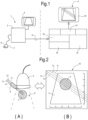
- Fig.1 shows a functional diagram of a device according to the invention associated with a generic ultrasound machine.
- Number 1 indicates, as a whole, an ultrasound machine, comprising a base unit 3 with a monitor 5 and a probe 7.
- the probe is equipped with a guide for needles or applicators.
- the probe 7 can be interchangeable, that is the same base unit 3 can be interfaced with different probes, according to the type of application.
- the probe 7 can be a convex probe, a linear probe, a phased array, an annular array, a biplanar probe, an endocavitary probe, or the like.
- the guide 9 can be of various types, and some exemplary embodiments will be described below.
- the device 11 comprises a board 16 for acquiring signals from the base unit 3, a video card 17 allowing to reproduce images on the monitor 15 based on data acquired by means of the acquiring board 16.
- Number 19 indicates a database where data from calibration of various ultrasound machines are stored, as described below in greater detail.
- the device 11 comprises a processing unit 21.
- Graphic elements may be associated with the cursors, for example concentric circles or measuring axes. These graphic elements allow to easily evaluate the distance of the needle tip from anatomical reference structures (tumor border, organ border, critical vital structures, etc.).
- Fig.8 illustrates, just by way of example, two graphical elements of this type, indicated with EG1 and EG2.
- multiple needles can be inserted along a plurality of guide traces, by means of a guide 9, which allows the simultaneous insertion of a number of needles smaller than the number of guide traces. It is even possible to insert two or more needles with a guide 9, which comprises a single insertion channel, as usually provided for the traditional guides used for biopsy needles of the prior art.
- Different methods can be provided for the insertion of multiple needles into the tissue T to be treated under ultrasound guidance with the aid of guide traces T1 - Tn and using a single guide 9.
- two or more needles can be inserted by means of a single guide according to parallel and equidistant trajectories. According to one embodiment, this can be obtained in the following way.
- a number N of guide traces T1 -Tn are displayed, retrieving data previously stored during a calibration step.
- the calibration can be performed as described above, providing, however, for generating, for a generic guide 9, a number N of guide traces greater than the number of guide channels.
- One of these guide traces is taken as the main trace.
- the main trace may be the first one, i.e. the one closest to the ultrasound probe 7 to which the guide 9 is attached.
- N-1 auxiliary guide traces are associated, parallel to the main guide trace, and preferably (but not necessarily) equidistant to one another, and in any case arranged at a known distance from one another and from the main trace.
- the auxiliary guide traces are used to insert, into the tissue T, the needles following the first one in a guided manner.
- the sonographically guided method for inserting the needles can be as follows:
- the first needle the ultrasound image of which is indicated with A1
- the guide trace T1 i.e. the first one and the highest of the guide traces T1-T5, which is taken as the main one;
- Fig.10B the probe has been moved to the right (looking at the drawing), as it can be understood as the image of the tumor tissue T has shifted to the left in the image I.
- the second needle the ultrasound image of which is indicated with A2 is inserted along the main guide trace T1.
- the position of the guide traces in Fig.10B has been obtained by making the guide trace T4 match the image of the first needle A1 inserted in the previous operating step. This as the operator has decided to insert the two needles A1, A2 at a mutual distance equal to three pitches between the equidistant guide traces T1-T5.
- This method together with the device 11, allows inserting more needles A1, A2 in a parallel manner and at a known distance chosen by the operator.
- a optical position marker can be used.
- An exemplary embodiment of the method in this form of implementation is illustrated in Figs. 13A, 13B .
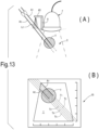
- An optical marker 43 is integral with the probe 7 directly or through a guide 9, which is in turn integral with the ultrasound probe 7.
- the optical marker 45 produces a light blade LL coinciding with the plane of the ultrasound probe 7, which also constitutes the needle insertion plane.
- the light blade is projected on the patient's body C and defines the plane where the needles shall be inserted.
- An improved version provides for the light blade to have light intensification points, i.e. points of greater light intensity, or for the light blade to be replaced by light beams lying on a plane.
- the guide traces T1 -Tn on the monitor 15 have been positioned so that the needles are inserted into the patient's body at the points identified by the optical marker so that the ultrasound images thereof are aligned with the guide traces.
- the guide traces T1-Tn have been positioned, during the calibration of the machine comprising the probe 7 and the optical marker 43, so that the image of the needles matches the guide traces when the needles are inserted in correspondence of the light traces formed by the optical marker.
- the system for obtaining marking light spots can use laser technology (e.g. diodes, thanks to the low cost, but also other sources) and diffractive lenses that can be designed to have any shape in space.
- laser technology e.g. diodes, thanks to the low cost, but also other sources
- diffractive lenses that can be designed to have any shape in space.
- the software for managing the device 11, run by the processing unit 21, can provide for superimposing on the monitor 15 a presumed treatment area, which helps the operator to plan the procedure.
- the presumed treatment area can be represented on the monitor by a closed line delimiting the perimeter of the presumed treatment area, or by a colored or transparent area superimposed on the image I of the tissue to be treated.
- the graphic elements used to show the presumed treatment area are such as to allow the visualization of the underlying anatomical structures shown on the monitor 15.
- the presumed treatment area is the area in which, based on experimental or simulation data, the thermal damage and therefore the death of the tumor cells is obtained, for example due to the effect of the energy irradiated by the needles or by other emitters inserted in certain positions in the tissue T to be treated.
- the input parameters for the planning software are derived from the user interface and are the following:
- Fig.14 shows a functional block diagram of the process for generating the images representing the presumed treatment area: the operator enters, through the user interface, the treatment data, which are acquired by the software run by the processing unit 21. Based on these data, using a mathematical model to predict the thermal damage and data from a database of simulations or experimental data, a two-dimensional matrix is generated, representative of the profile of the presumed treatment area calculated by the software. The two-dimensional matrix is then transferred, in the form of a colored area, profile of the area or in another way, on the monitor 15.
- the same software can be used retrospectively once the applicator needles have been inserted into the human body, to verify the correct position thereof. To this end, it is possible to do the following. Once the needles have been inserted, they are visible on the monitor. The operator can position the cursors C1, C2 at the end of each needle. Based on the cursors position, the planning software obtains the treatment area and displays it on the monitor. The operator can verify that the treatment area is correctly positioned (superimposed) on the portion of tissue T that must be effectively treated. Otherwise, he can move one or the other of the inserted needles and, repositioning the cursor(s), the software recalculates the perimeter of the treated area for newly controlling the correct positioning with respect to the volume of tissues T to be treated.
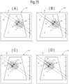
- a single-channel guide shall be used for a single needle, it is possible to perform what described below with reference to Figs.15A-15D .
- the guide is a single-channel guide
- only one single main guide trace Tp is initially displayed on the monitor 15. This trace corresponds to the trajectory followed by the needle when it is inserted into the single channel of the guide 9 when said guide, carried by the ultrasound probe 7, is in the current position, through which the image I displayed on the monitor 15 has been acquired.
- the operator places a cursor C1, C2 on each of the two guide traces Tp and Ts. Based on the acquired data, the planning software calculates a presumed treatment area AT ( Fig. 15A ).
- This presumed treatment area is essentially the area that is reached by the energy supplied by dispensers, for example by optical fibers coupled to laser sources, inserted through the treatment needles.
- the operator arranges the probe and the cursors C1, C2 so that the presumed treatment area AT coincides with the tumor mass T, or in general with the volume T to be treated.
- Fig. 15A the presumed treated area AT is substantially centered on the tumor mass T.
- the treatment planning has been therefore carried out.
- the shape and the dimension of the presumed treatment area AT can be defined by the operator by moving the cursors C1, C2 along the two guide traces Tp and Ts.
- the first needle can be inserted through the guide 9, keeping the position of the ultrasound probe 7, and therefore of the guide 9, fixed.
- the image of the first needle A1 appears along the main guide trace Tp.
- the first needle A1 is inserted until its tip reaches the first cursor C1. It moves along the trajectory defined by the main guide trace Tp, which corresponds to the trajectory defined by the single guide channel with which the guide 9 is provided.
- Fig. 15B shows the ultrasound image representing the final arrangement when the needle A1 has been completely inserted.
- the second needle can be inserted by informing the system, through a user interface, that this second step is starting.
- the needle A1 inserted into the patient's body is released from the channel of the guide 9 to allow the ultrasound probe 7 to move and also to allow the insertion of a second needle into the single channel of the guide 9.
- the operator moves the probe 7 so that the image of the mass T to be treated, the image of the inserted needle A1, the cursors C1, C2 and the traces Ts and Tp are positioned as shown in Fig. 15C , i.e. with the inserted needle A1 aligned on the secondary guide trace Ts.
- the probe 7 has been displaced so that the secondary guide trace Ts is aligned with the image of the needle A1 already inserted into the patient.
- the tip of the needle A1 coincides with the respective cursor C1.
- the second needle will be inserted into the guide.
- the image thereof will appear on the main guide trace Tp and the insertion will finish when the tip of the second needle A2 on the monitor 15 reaches the second cursor C2 lying on the main guide trace Tp, as shown in Fig. 15D .
- the ultrasound speed depends on several factors, including the temperature and the nature of the medium (tissue) in which the ultrasounds propagate.
- the base unit 3 is not adapted to know the properties of the material subjected to the sonographic assay and therefore, to give an indication of the spatial depth measurements, a constant speed value is taken as average reference for all tissues (1540 m/s, which is the speed of ultrasounds in water at 37°C).
- the following table shows an evaluation of the ultrasound average speed in various tissues, taken from scientific literature data (see for example: Goss, SA, Johnston, RL, and Dunn , F. (1978).
- this needle (or more precisely the sonographic image thereof on the monitor 15) is not parallel to the respective guide trace shown on the monitor 15 and has an inclination lower (ultrasound speed greater than reference speed) or higher (ultrasound speed lower than the reference speed) than the inclination of the guide trace.
- a fine calibration can be performed by superimposing the guide trace on the image of the inserted needle, both shown on the monitor 15.
- the calibration can be performed by acting on the typical parameters of the guide trace, i.e. angular coefficient and intercepting point, i.e. the point of intersection between the coordinate of the image depth.
- This small recalibration (we are talking about values ranging from a few percent to 10%, wherein 5% is the typical value) makes it possible to adapt the plurality of guide traces on the monitor 15 to the type of tissue that is sonographically displayed and not to make mistakes when inserting the subsequent needles.
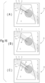
- FIG. 16A shows the image I on the monitor 15 with five guide traces T1-T5 and the image of the first inserted needle A1. It should be noted that the insertion of the first needle on the guide trace T4 (wherein the traces are numbered from the top to the bottom) results in the needle tip to differ from the presumed trajectory.
- Fig.16B shows the result of the fine recalibration described above, which involves the superimposition of the guide trace T4 on the image of the first (and for the moment the only) inserted needle A1.
- the insertion of a second needle A1 along the guide trace T2 ( Fig.16C ) now follows the presumed trajectory, defined by the guide trace T2.
Landscapes
- Health & Medical Sciences (AREA)
- Life Sciences & Earth Sciences (AREA)
- Surgery (AREA)
- Engineering & Computer Science (AREA)
- Public Health (AREA)
- Molecular Biology (AREA)
- Veterinary Medicine (AREA)
- Nuclear Medicine, Radiotherapy & Molecular Imaging (AREA)
- Biomedical Technology (AREA)
- Heart & Thoracic Surgery (AREA)
- Medical Informatics (AREA)
- General Health & Medical Sciences (AREA)
- Animal Behavior & Ethology (AREA)
- Pathology (AREA)
- Biophysics (AREA)
- Physics & Mathematics (AREA)
- Radiology & Medical Imaging (AREA)
- Robotics (AREA)
- Computer Vision & Pattern Recognition (AREA)
- Ultra Sonic Daignosis Equipment (AREA)
Description
- Devices and computer programs are disclosed herein for positioning, by means of ultrasound guidance, applicators in minimally invasive procedures for the treatment of tumors or the like.
- The minimally invasive techniques for treating tumors have been known for more than twenty years. The various techniques provide for the use of different forms of energy (radio frequency, micro waves, laser, cold, electrical pulses) to induce necrosis of tumor cells. Currently, the purpose of these techniques in oncology field is to induce complete necrosis of the malignant tumor in all cases where the exeresis surgery is too risky, or in inoperable tumors. In palliative care applications, the minimally invasive techniques still allow a therapy prolonging the patient's life while maintaining an acceptable quality thereof. Some minimally invasive techniques are also used in benign tumors when the mass growth causes compression symptoms or aesthetic damage (if the tumor is growing in superficial organs).
- Even in the case of benign tumors, surgery could be complex and/or devastating with possible severe and/or disabling complications or with significant aesthetic implications. The minimally invasive procedures are generally performed when the patient is in deep sedation or local anesthesia; they do not leave traces on the body thanks to the limited size of the needles, produce effects that are localized to the area to be treated with consequently very short recovery times for the patient and negligible complications or side effects.
- All minimally invasive techniques provide for inserting one or more applicators (energy dispensers) into the tumor, under guidance by ultrasound (sonography), tomography or magnetic resonance, and supplying a certain amount of energy that interacts with the tumor cells, causing the death thereof.
- In this field, it is essential to have a guide system for correctly positioning the applicators, and a treatment planning software supporting the doctor in choosing the optimal treatment strategy, enhancing the treatment safety, effectiveness and speed. All these aspects contribute to keep the patient management costs low.
-
US 6733458 andEP3153104 disclose ultrasound equipment that can be provided with probes and needle guides in combination with a sensor for detecting actual position of the needle. With this arrangement it is possible to reproduce on the same ultrasound image generated on the basis of the signals collected by the ultrasound probe, the image of the needle and it is therefore possible to display the trace along which the needle will be inserted. This is not possible if the ultrasound system is not provided with sensors to identify the position and direction of the needle, and with processing members allowing generating the needle insertion trace on the basis of its actual physical position. - A computer program according to
claim 1 and a corresponding device according toclaim 9 for guiding minimally invasive procedures by means of an ultrasound system are disclosed. - According to one aspect, a computer program is disclosed for guiding minimally invasive procedures by means of an ultrasound system, comprising the step of collecting data indicative of an ultrasound machine comprising: a base unit, a probe associated with the base unit, and a needle guide associated with the probe for guiding needles in a volume subjected to ultrasound imaging by means of the probe and the base unit. The data indicative of the ultrasound machine can be entered by an operator through a user interface of a machine configured to implement the method of the invention.
- "Data indicative of an ultrasound machine" refers, in this context, to data that allow to define the components of the ultrasound machine and therefore, as it will be described in greater detail bellow, allow to superimpose to an ultrasound image, acquired through the ultrasound machine, needle guide traces for performing various treatments, involving, for example, laser energy supply or the supply of other form of energy in a tissue to be treated.
- The computer program may also comprise a step of recovering, from a data base, information associated with the ultrasound machine. On a monitor, usually other than the monitor or screen of the ultrasound machine, an ultrasound image acquired through the ultrasound machine is displayed. A set of guide traces is superimposed to this ultrasound image so as to guide the insertion of needles in the volume subjected to sonographic imaging. Thanks to the information recovered from the database and associated with the ultrasound machine identified by means of the indicative data, the set of guide traces can be coordinated with the ultrasound images displayed on the monitor.
- The computer program can be performed in real time. This means that the ultrasound image is acquired directly by the ultrasound machine while the probe is applied to the patient.
- The set of guide traces may comprise only one trace or a plurality of guide traces. The guide traces can be parallel to, and equidistant from, one another. More in general, the number and the mutual position of the guide traces can be determined by the features of the ultrasound machine used, for example by the structural features of the needle guide associated with the probe.
- The computer program may also comprise the step of displaying on the monitor the image of one or more needles arranged in the needle guide and inserted in the volume subjected to ultrasound imaging, said image being acquired through the probe and the base unit.
- In practical examples, the database contains a plurality of data sets, each data set defining a respective set of guide traces corresponding to a given ultrasound machine. Practically, according to embodiments described herein, once the type of ultrasound machine has been determined, through the data identifying this machine, it is possible to recover from the database information allowing to correctly represent the guide traces on the ultrasound image ultrasound obtained from the ultrasound machine.
- By collecting sufficient information, which can be acquired for example by means of a calibration step, and storing it in a database, in general, the method disclosed herein allows generating guide traces on a monitor and guiding needles in needle guides associated with the probe, for any ultrasound machine.
- A device is also disclosed for guiding minimally invasive procedures by means of an ultrasound system, comprising in combination: a monitor; a board for acquiring sequences of ultrasound images from an ultrasound machine; a database containing information on configurations of ultrasound machines that can interface the device; a processing unit, configured to: receive sequences of ultrasound images from the ultrasound machine; display said ultrasound images on the monitor; superimpose to said ultrasound images on the monitor a set of guide traces for guiding the insertion of needles, said guide traces being coordinated with the ultrasound images through the information recovered from the database.
- The invention will be better understood by following the description and the accompanying drawing, which shows a non-limiting example of embodiment of the invention. More in particular, in the drawing:
-
Fig. 1 is a block diagram of an ultrasound machine interfacing a device according to the present description; -
Figs. 2A and 2B show a diagram of an ultrasound probe associated with a needle guide and applied to the body of a patient, and the ultrasound image thereof displayed on the monitor of the device; -
Figs. 3A, 3B show diagrams of the ultrasound image in a calibration step; -
Fig.4 is a summary diagram of the parameters useful for calibration; -
Fig. 5 is a diagram of the steps of recovering data from a database; - Fig. 6 is a flow chart of the database data recovery operations for subsequently reconstructing the guide traces on the ultrasound image displayed on the monitor of the device;
-
Figs. 7 and 8 are simplified ultrasound images showing the use of cursors to facilitate the positioning of the needles through a ultrasound-guided procedure; -
Figs. 9A, 9B, 10A and 10B are diagrams of an ultrasound probe and the respective needle guide, as well as the related ultrasound images, in a step of inserting multiple needles by means of a single-channel needle-guide, in a possible operating mode; -
Figs. 11A, 11B, 12A, 12B are diagrams of an ultrasound probe and the respective needle guide, as well as the related ultrasound images, in a step of inserting multiple needles by means of a single-channel needle-guide, in a further operating mode; -
Figs 13A, 13B are diagrams of an ultrasound probe and of the corresponding ultrasound image in a mode of guiding the needles through an optical system; -
Figures 14 ,15 and16 are diagrams showing the treatment planning system by means of the device and the method described herein. - The detailed description below of example embodiments is made with reference to the attached drawing. The same reference numbers in different figures identify equal or similar elements. Moreover, the drawings are not necessarily to scale. The detailed description below does not limit the invention. The protective scope of the present invention is defined by the attached claims.
- In the description, the reference to "an embodiment", "the embodiment" or "some embodiments" means that a particular feature, structure or element described with reference to an embodiment is comprised in at least one embodiment of the described object. The sentences "in an embodiment" or "in the embodiment" or "in some embodiments" in the description do not therefore necessarily refer to the same embodiment or embodiments. The particular features, structures or elements can be furthermore combined in any adequate way in one or more embodiments.
- Briefly, a device is disclosed, which is adapted to interface a generic ultrasound system and is provided with a processing unit allowing to display, on a monitor, an ultrasound image acquired by means of the ultrasound machine, and to which a set of one or more guide traces is superimposed, facilitating the insertion, under ultrasound guidance, of needles in the portion subjected to ultrasound imaging. The device substantially receives a sequence of ultrasound images (ultrasound signal or B-Mode) from a generic ultrasound machine, detects the display settings (depth and width) and overlaps, on the monitor, one or more guide traces indicating the directions, along which a needle applicator or an electrode can be inserted, according to the guide system connected to an ultrasound probe associated with the ultrasound machine interfacing the device. The guide system can be a single-channel system (for example a generic bioptic guide) or a multi-channel system (as disclosed, for example, in Italian patent application no. FI2012A000045), allowing inserting one or more applicators simultaneously. The device is provided with an input receiving a video signal from a generic ultrasound machine, for example a VGA, DVI, HDMI, S-Video signal, from which it acquires the images at the same frame rate (or by means of subsampling). The frame rate can even reach 100Hz, although usually lower frequencies are used, in the range of 20-40Hz.
- The guide traces must be coordinated with the ultrasound image. To allow a flexible use of the device, interfacing it with a plurality of different ultrasound machines, the device comprises a database, in which information, obtainable by means of calibration, is stored, based on which the processing unit generates the guide traces correctly superimposed to the ultrasound image obtained from the ultrasound machine.
-
Fig.1 shows a functional diagram of a device according to the invention associated with a generic ultrasound machine.Number 1 indicates, as a whole, an ultrasound machine, comprising abase unit 3 with amonitor 5 and aprobe 7. The probe is equipped with a guide for needles or applicators. Theprobe 7 can be interchangeable, that is thesame base unit 3 can be interfaced with different probes, according to the type of application. For example, theprobe 7 can be a convex probe, a linear probe, a phased array, an annular array, a biplanar probe, an endocavitary probe, or the like. - The
guide 9 can be of various types, and some exemplary embodiments will be described below. - Within the present description and the appended claims, the term "needle" refers to any diagnostic or therapeutic tool for localized interventions, having a rod-like shape, at least for part of its extension. In some embodiments, the needle may be a cannula, in which a light guide, for example an optical guide, is inserted, through which electromagnetic energy is conveyed in the tissue to be treated, generated by a laser source with suitable supply characteristics, known to those skilled in the art.
- Although in the following description specific reference will be made to systems for inserting optical fibers through cannulae, it shall be understood that the needles that can be used within this context and with the device described herein may have different forms and functions; for example they can be rod-like or linear elements having diagnostic functions instead of therapeutic functions, or they can be tools for conveying, in the treated tissues, energy different than laser energy, such as for example ultrasounds, radio frequency currents, and in general forms of energy useful for treating tissues, for example, although not exclusively, for destroying tumor cells.
- The
base unit 3 interfaces adevice 11, which forms a specific object of the invention, and which receives images from the base unit and uses them as described below. In practice, the images transferred from thebase unit 3 to thedevice 11 are constituted by electrical pulses conveyed through a connectingcable 13, which are acquired by thedevice 11 and converted into an image displayed on amonitor 15, with which thedevice 11 is provided. Usually, themonitor 15 is a display device separate and distinct from the screen or monitor 5, with which thebase unit 3 is provided. - The
device 11 comprises aboard 16 for acquiring signals from thebase unit 3, avideo card 17 allowing to reproduce images on themonitor 15 based on data acquired by means of the acquiringboard 16.Number 19 indicates a database where data from calibration of various ultrasound machines are stored, as described below in greater detail. Lastly, thedevice 11 comprises aprocessing unit 21. -
Figs.2A and 2B show in greater detail an embodiment of anultrasound probe 7 and of aguide 9 for inserting, into the body C of a patient, a plurality of needles for treating a portion of tissue, for example of a tumor tissue T. As mentioned, the needles can be cannulae within which optical fibers are conveyed to convey electromagnetic radiation from a laser source, not shown. L1, L2, L3, and L4 indicate the physical trajectories along which the needles are inserted. The trajectories L1-L4, their positioning with respect to theprobe 7 and therefore with respect to the patient's body C, as well as their reciprocal distance depend on the shape of theguide 9 and on the way it is applied to theprobe 7. - As it will be better described below, guide traces T1, T2, T3, T4 are displayed on the
monitor 15 of thedevice 11, superimposed to the ultrasound image I displayed on themonitor 15 and reconstructed on the basis of the signals provided by thebase unit 3. Between the guide traces T1, T2, T3 and T4 and the trajectories L1, L2, L3, L4 there is a correlation, which allows the operator to position theprobe 7, and therefore theguide 9, with respect to the patient's body C, so that the guide traces T1-T4 intersect the areas to be treated shown on the image I displayed on themonitor 15. - The operator essentially observes, on the
monitor 15 of thedevice 11, the tissue to be treated, for example a tumor T that shall be necrotized by means of laser irradiation. The operator can move theprobe 7 on the patient's body C so as correctly to position theguide 9 with respect to the patient's body. The correct position is achieved when the guide traces T1-T4, corresponding to the trajectories L1-L4, intersect the tumor mass T in the desired area. At this point the operator can insert the needles into theguide 9. The insertion can be sonographically guided by observing the echogenic needle, whose image will appear on themonitor 15 of thedevice 11, when it enters the field of view of theprobe 7. - In this particular example, the
guide 9 provides for a plurality of insertion lines, i.e. a plurality of trajectories L1-L4 for inserting as many needles, to which trajectories a plurality of guide traces T1-T4, displayed on themonitor 15, corresponds. In practice, theguide 9 can comprise a plurality of channels or grooves, in each of which a single needle can be inserted. A possible structure of the multi-channel guide 9 is described inItalian patent application no. FI2012A000045 - In other embodiments, the
guide 9 may be configured to guide a single needle, i.e. it can have only one needle guide channel. This is typically the case of a generic bioptic guide. In this case, a single guide trace will appear on themonitor 15, overlapping the image I of the tissue volume subjected to imaging. - It should be noted that, as sonography is a spatial imaging system according to a conformal mapping between anatomical sections and image, the guide traces T1-T4 displayed on the
monitor 15 will have the same inclination as the trajectories L1-L4 of the needles in the real space, identified by the inclination of theguide 9 or more exactly of the single channels of theguide 9. - In general, there are adjustable needle-
guide kits 9 supporting different angles (among which during surgery one is selected for the specific case) or needle-guide devices 9, for which the insertion angle shall be every time identified by the doctor according to the anatomical structures in the image. - The
device 11 can be interfaced with a plurality ofdifferent base units 3, each of which can be provided with a plurality ofdifferent probes 7. One or moredifferent guides 9 can be associated to thevarious probes 7. In order to consistently display the guide traces T1-T4 on the image I of themonitor 15, so that the traces T1-T4 have, with respect to the image I, a position corresponding to the real position of the trajectories L1-L4 with respect to the tissue to be treated, a calibration step is required for each possible configuration of theultrasound machine 1. The calibration step is preparatory to all subsequent operations; namely, it allows tracing the guide traces on the monitor the first time and saving data for the following sessions, depending on the model ofbase unit 3,probe 7 andguide 9. - The calibration step will be described below with specific reference to
Figs.3A and 3B . - After having set a scanning depth on the
base unit 3, theprobe 7 and theguide 9 connected thereto (which identifies a given needle insertion angle), a tank containing a liquid, for example water, functioning as an ultrasound conductive means, is used to simulate the tissue subjected to imaging. It is assumed that, in water at room temperature, the ultrasound propagation speed is comparable to that in biological tissues (1540 m/s). - An echogenic needle is inserted into one of the channels provided in the
guide 9. Theprobe 7 with theguide 9 and the needle inserted therein is placed in the tank so that the needle is clearly visible in the ultrasound image acquired by thebase unit 3 and shown on themonitor 15 of thedevice 11. - Guide traces in random positions will be also visible on the
monitor 15, which are generated by theprocessing unit 21 and superimposed to the ultrasound image I on themonitor 15. The calibration step consists in making one of the guide traces T1-T4 match the ultrasound image of the needle, until they completely superimpose each other. - In this regard it should be noted that the number of guide traces T1-T4 must be set according to the
ultrasound machine 1 used, for which the calibration must be performed. This number depends on the structure of theguide 9 and corresponds to the number of guide channels. In the illustrated example, theguide 9 has four channels for inserting four needles along insertion trajectories L1-L4 and therefore four guide trajectories T1-T4 must be superimposed to the ultrasound image I displayed on themonitor 15. - The guide trajectory that, during the calibration step, is superimposed on the needle ultrasound image shall be the one corresponding to the position of the needle inserted into the guide. For example, with reference to
Fig. 2 , if a needle has been inserted in the channel closest to theprobe 7, corresponding to the insertion trajectory L1, during the calibration step it will be necessary to superimpose the ultrasound image of the needle on the guide trace T1. - To allow superimposing the guide trace on the ultrasound image of the needle on the
monitor 15, theprocessing unit 21 of thedevice 11 allows changing the typical parameters of the guide trace, i.e. the parameters identifying the position in the image plane. These parameters are the angular coefficient and the intercept point with the depth axis, i.e. the vertical axis on themonitor 15. - If the geometric relationship between the channels of the
guide 9 defining the needle trajectories L1-L4 is known, it will be sufficient to calibrate a single guide trace T1 and to generate the family of guide traces T1-T4 (in a number equal to the number of needle guide channels available in the guide 9) by using the geometric relationship, i.e. the information on the mutual position of the various needle guide channels and therefore of the trajectories L1-L4. If the geometric relationship of the channels is not known (for example in the case of a marketed guide), the calibration operation can be repeated for each trajectory L1-L4 corresponding to each channel of theguide 9. - Some guides 9 may have an adjustable inclination with respect to the
probe 7 to which they are attached. In this case, the calibration shall be repeated for every angle that the guide, and therefore the trajectories L1-L4, can assume with respect to theprobe 7, on which theguide 9 is fixed. - During the calibration step the user shall also provide other information to the
device 11, so as to make it adapted to operate independently every time the image coming from the base unit changes, once the type of usedbase unit 3,probe 7 andguide 9 has been selected. The parameters that can change and that affect the identification of the guide traces are the following: - depth value acting on the dimensions of the ultrasound image and therefore on the centimeter scales laterally
- visualization type: rectangular, trapezoidal, sectoral, which can affect the dimensions of the ultrasound representation on the monitor
- left-right orientation
- up-down orientation
- During the calibration step, the
device 11 requires some information necessary for the subsequent tracing of the guide traces T1-T4. In particular, the user will identify on the monitor: - the position and dimensions of the ultrasound image within the
monitor 15; - the position and dimensions of the re-tracing area;
- the scanning mode and the mode of representation on the monitor: rectangular, trapezoidal, sectoral;
- the position of the depth value on the monitor (if any);
- the position of the vertical and horizontal centimeter scale with the minimum, maximum and intermediate values of the centimeter scale (from which the cm/pixel pitch is obtained);
- the orientation of the ultrasound image (left-right or right-left with respect to the probe scanning).
-
Figs.3A and 3B show, by way of example, the information and the corresponding graphic parts required by the user during the calibration step for two different depth values that can be set on the base unit. - The calibration shall be repeated for each possible configuration of the
monitor 15 determined by the parameters depth and ultrasound visualization (and by other parameters that can affect the image presentation). - Once the calibration is finished, a configuration of values is obtained comprising a first set of value pairs (angular coefficient and intercept point) of the guide traces, in which each pair uniquely identifies a guide trace on the
monitor 15. The first set contains as many pairs of values as many guide traces for thespecific guide 9. If theguide 9 is a single-needle guide, the first set contains a single pair of values. In general, if theguide 9 contains N channels for N needles, the first set of values contains N pairs of values, one for each needle that can be inserted into theguide 9. - Following the calibration described above, in addition to the first set of value pairs, a second set is obtained of other parameters related to the
ultrasound machine 1, i.e. related to the combination ofbase unit 3,probe 7 andguide 9, as well as to the visualization mode, on which the calibration has been made. -
Fig.4 graphically summarizes the data of the second set. - The two data sets are stored in the
database 19 of thedevice 11. The data of the second set and the associated data of the first set can be therefore retrieved from thedatabase 19 when necessary, i.e. whenever the same configuration of theultrasound machine 1 is used. - During the operating steps, every time the
device 11 interfaces an ultrasound system consisting of base unit-probe-guide, i.e. anultrasound machine 1, the user indicates the model ofbase unit 3,probe 7 and guide 9 by means of a menu in a user interface, which can be displayed on themonitor 15. Theprocessing unit 21 is configured to retrieve, from thedatabase 19, the information previously stored during the calibration of theultrasound machine 1 and to perform a series of processing operations necessary for retracing the guide traces T1-T4 on themonitor 15 from the ultrasound image I for any depth or display value selected by the user on thebase unit 3. To this end, theprocessing unit 21 can be configured to receive, from thebase unit 3, information on the depth and display mode selected by the operator. Thedatabase 19 contains the information, acquired during the calibration step, necessary to retrace the guide traces T1-T4 as these two parameters change. - If the previously described calibration step has not been performed for the selected
ultrasound machine 1, a calibration step shall be performed for the new combination. -
Fig. 5 illustrates a graphical user interface that can be used to select a given configuration of theultrasound machine 1 and to retrieve the related data from thedatabase 19. The interface can be displayed on themonitor 15, and the various options can be selected by means of a pointer, for example controlled by a mouse. In other embodiments, themonitor 15 can be a touch screen monitor, allowing the user to select the single items of theultrasound machine 1 by touching themonitor 15. As shown inFig.5 , in the first section on the left a base unit can be selected (base unit-1, base unit-22, ... base unit-N), in the second section aprobe 7 can be selected (probe-1, probe-2, ... probe-N), and in the third section a guide 9 (guide-1, guide-2, ... guide-N) can be selected. All the base units, probes and guides for which calibration has been performed can be displayed on the monitor. If one of the three items to be selected is not listed, the user can press or click the "unavailable" button, thus starting a new calibration. If the selected combination is available, i.e. if thedatabase 19 contains the information necessary for retracement of the guide traces T1-T4 for that combination of components, the "retrieve-configuration" button can be pressed for retrieving the configuration from thedatabase 19. - It should be noted that there may be cases where all the selected elements (base unit, probe, guide) are present in the interface, but the specific combination chosen has not been calibrated. Also in this case, and not only if one of the three elements is not present in the lists displayed on the monitor, it is necessary to perform a new calibration. For example, let's assume that for a given
base unit 3 calibrations have been made with a probe 7A and a probe 7B by associating a guide 9A to the probe 7A and a guide 9B to the probe 7B, but that theultrasound machine 1 constituted by thebase unit 3, the probe 7B and the guide 9A has not been calibrated. In this case, even if theelements 3, 7B and 9A are already present, it will be necessary to perform a new calibration. - In particular, the management software will search, in the areas indicated by the configuration retrieved from the
database 19, the vertical scale and the depth value (if any). For the area related to the vertical scale, the algorithm provides for the search and identification of the centimeter notches which allow calculating the depth/pixel ratio useful for the retracement of the guide traces T1-T4. If the depth value is displayed on the monitor, the algorithm provides for the identification of the number written in the relevant area by means of a sub-algorithm of numerical recognition. Once the number has been recognized, the algorithm can calculate the depth/pixel ratio by dividing this value by the depth (in pixels) of the ultrasound image. - Fig.6 summarizes in a flowchart the process of retrieving data from the
database 19 and retracing the guide traces T1-T4 once the user has communicated to thedevice 11 the data relating to theultrasound machine 1. - With the disclosed
device 11 it is possible to display on themonitor 15 the guide traces T1-T4 corresponding to the real trajectories L1-L4 along which the needles guided in theguide 9 are inserted into the tissue T to be treated. Thanks to the fact that it is possible to store in adatabase 19 the calibration data relating to a plurality of possible combinations ofultrasound machines 1, thedevice 11 provides the operator with an effective sonographically guided system for inserting the needles, using usually marketed base units, probes and guides, in various possible combinations. - Starting from the base configuration described above, further evolutions and improvements of the
device 11 are possible. - According to some embodiments, the
processing unit 21 can be adapted to generate, and to superimpose on themonitor 15 to the image I of the tissue subjected to imaging, not only the guide traces T1-T4, but also one or more cursors that can slide along one or the other of the available guide traces T1-T4. The cursors indicate the position that the needle feeder or the point of the energy applicator shall achieve, and represent reference points for the operator for planning and inserting the needles. The cursors are then positioned by the operator, for example by means of a mouse or other interface device. -
Fig. 7 schematically shows an image I displayed on themonitor 15. The image I contains the tumor area T to be treated. T1-T5 indicate the guide traces (in this example five guide traces) for the needles (as many as the guide traces, in this case five needles) that can be guided through theguide 9 associated with theprobe 7. C1 and C2 indicate two cursors movable on the image I, which are displayed at the points where the operator will bring the ends of respective needles or other energy dispensers. The positions of the cursors are determined by the operator based on anatomical and procedural considerations according to the technology used for the treatment. Once the needles have been inserted, their tips must coincide with the cursors in the image I. - Graphic elements may be associated with the cursors, for example concentric circles or measuring axes. These graphic elements allow to easily evaluate the distance of the needle tip from anatomical reference structures (tumor border, organ border, critical vital structures, etc.).
Fig.8 illustrates, just by way of example, two graphical elements of this type, indicated with EG1 and EG2. - In the embodiments described above, it has been assumed to use
guides 9 with a plurality of channels for a plurality of needles to be inserted into the tissue T to be treated and to display on the monitor 15 a number of guide traces T1-Tn corresponding to the number of guide channels and consequent insertion trajectories L1-Ln with which theguide 9 is provided. - This is, however, not mandatory. In fact, with the
device 11 disclosed herein, multiple needles can be inserted along a plurality of guide traces, by means of aguide 9, which allows the simultaneous insertion of a number of needles smaller than the number of guide traces. It is even possible to insert two or more needles with aguide 9, which comprises a single insertion channel, as usually provided for the traditional guides used for biopsy needles of the prior art. - Different methods can be provided for the insertion of multiple needles into the tissue T to be treated under ultrasound guidance with the aid of guide traces T1 - Tn and using a
single guide 9. For example, two or more needles can be inserted by means of a single guide according to parallel and equidistant trajectories. According to one embodiment, this can be obtained in the following way. - On the
monitor 15, a number N of guide traces T1 -Tn are displayed, retrieving data previously stored during a calibration step. In general terms, the calibration can be performed as described above, providing, however, for generating, for ageneric guide 9, a number N of guide traces greater than the number of guide channels. One of these guide traces is taken as the main trace. For example, the main trace may be the first one, i.e. the one closest to theultrasound probe 7 to which theguide 9 is attached. To the main guide trace, which corresponds to the position of the single needle insertable in the guide, N-1 auxiliary guide traces are associated, parallel to the main guide trace, and preferably (but not necessarily) equidistant to one another, and in any case arranged at a known distance from one another and from the main trace. The auxiliary guide traces are used to insert, into the tissue T, the needles following the first one in a guided manner. - In this case the sonographically guided method for inserting the needles can be as follows:
- 1) The first needle is inserted using the main guide trace on the
monitor 15 as guide trace of the needle coinciding with the trajectory of the needle of the single-channel guide 9; - 2) as the needle has been inserted, it is released from the
needle guide 9, so that theguide 9 and theprobe 7 integral therewith can be moved, while the inserted needle remains in position; - 3) the
probe 7 is moved keeping the ultrasound view of the inserted needle, i.e. theultrasound probe 7 is moved so that the already inserted needle remains on the plane of propagation of the ultrasound signals of the probe; - 4) the already inserted needle is aligned with one of the auxiliary guide traces visible on the
monitor 15 at a preselected distance from the main guide trace; - 5) when the alignment has been done, a second needle is inserted in the single channel of the
guide 9, the second needle following the main trace; - 6) the second needle is released and, if necessary, the procedure can be repeated for inserting a third needle and any further needles, otherwise the needle insertion step is ended.
-
Figs.9A, 9B and 10A, 10B graphically illustrate the process described above.Figs.9A, 9B show respectively: - the position of the
ultrasound probe 7 on the patient's body with a first needle A1 inserted through theguide 9 along the first insertion trajectory L1; - and the position of the
ultrasound probe 7 moved to the right with respect to the volume of tumor tissue T to be treated, with the needle A1 released from the single-channel guide 9 and a second needle A2 inserted along a trajectory L2, penetrating into the tissue T. -
Figs.10A and 10B show the images on themonitor 15 corresponding to the two positions ofFigs. 9A, 9B : - in
Fig. 10A the first needle, the ultrasound image of which is indicated with A1, has been inserted along the guide trace T1, i.e. the first one and the highest of the guide traces T1-T5, which is taken as the main one; - in
Fig.10B the probe has been moved to the right (looking at the drawing), as it can be understood as the image of the tumor tissue T has shifted to the left in the image I. The second needle, the ultrasound image of which is indicated with A2, is inserted along the main guide trace T1. The position of the guide traces inFig.10B has been obtained by making the guide trace T4 match the image of the first needle A1 inserted in the previous operating step. This as the operator has decided to insert the two needles A1, A2 at a mutual distance equal to three pitches between the equidistant guide traces T1-T5. - This method, together with the
device 11, allows inserting more needles A1, A2 in a parallel manner and at a known distance chosen by the operator. - In other embodiments the guide traces T1-Tn on the
monitor 15 can be advantageously used to insert a plurality of needles using a single-channel guide 9 (e.g. a generic biopsy guide) at a known distance and keeping the needles parallel by using an outer needle spacing tool having a plurality of channels (with a distance consistent with that of the guide traces shown on the monitor 15).Figs. 11A, 11B, and 12A, 12B illustrate this method for inserting the needles.Number 41 indicates the outer tool comprising, in this example, five equidistant channels. The same reference numbers indicate parts and components identical to those described with reference toFigs. 9A, 9B and 10A, 10B . - In other embodiments, a optical position marker can be used. An exemplary embodiment of the method in this form of implementation is illustrated in
Figs. 13A, 13B . Anoptical marker 43 is integral with theprobe 7 directly or through aguide 9, which is in turn integral with theultrasound probe 7. The optical marker 45 produces a light blade LL coinciding with the plane of theultrasound probe 7, which also constitutes the needle insertion plane. The light blade is projected on the patient's body C and defines the plane where the needles shall be inserted. An improved version provides for the light blade to have light intensification points, i.e. points of greater light intensity, or for the light blade to be replaced by light beams lying on a plane. The points of greater intensity of the light blade or the light beams project light spots on the patient's epidermis, next to theultrasound probe 7. These points identify the needle entry points determined by the guide traces on themonitor 15. In an initial calibration step, as described above, the guide traces T1 -Tn on themonitor 15 have been positioned so that the needles are inserted into the patient's body at the points identified by the optical marker so that the ultrasound images thereof are aligned with the guide traces. In other words, the guide traces T1-Tn have been positioned, during the calibration of the machine comprising theprobe 7 and theoptical marker 43, so that the image of the needles matches the guide traces when the needles are inserted in correspondence of the light traces formed by the optical marker. - It is up to the operator's skill, then, to insert the needles with the right inclination, so that their ultrasound image on the
monitor 15 follows the respective guide traces. In case of incorrect inclination of the needle, this latter can be extracted and inserted again. - For example, if a needle shall be inserted along the guide trace T1, the patient's skin must be perforated at the first light spot formed by the
optical marker 43. The systems for obtaining marking light spots can use laser technology (e.g. diodes, thanks to the low cost, but also other sources) and diffractive lenses that can be designed to have any shape in space. - In an improved embodiment, the software for managing the
device 11, run by theprocessing unit 21, can provide for superimposing on the monitor 15 a presumed treatment area, which helps the operator to plan the procedure. The presumed treatment area can be represented on the monitor by a closed line delimiting the perimeter of the presumed treatment area, or by a colored or transparent area superimposed on the image I of the tissue to be treated. Anyway, the graphic elements used to show the presumed treatment area are such as to allow the visualization of the underlying anatomical structures shown on themonitor 15. - The presumed treatment area is the area in which, based on experimental or simulation data, the thermal damage and therefore the death of the tumor cells is obtained, for example due to the effect of the energy irradiated by the needles or by other emitters inserted in certain positions in the tissue T to be treated.
- The figures representing the presumed treatment area come from a pre-simulation database (if coming from an algorithm of induced tissue damage simulation) or from stored experimental data. Practically, the presumed treatment area is quickly identified by the software on the basis of input parameters, defined below, and are scaled, appropriately directed and lastly superimposed on the
monitor 15 according to the diagram of the following figure using as reference point the source of energy (usually the tip of the needle or needles) and cursors, if any, on the guide traces. - The input parameters for the planning software are derived from the user interface and are the following:
- insertion angle (identified by the angle of the guide traces)
- number of applicators (1, 2 or more than 2)
- position of the individual applicators along the respective guide traces
- energy power and dose (treatment times)
- number of pull-backs, i.e. of successive irradiations through the same needle in successive positions along the same guide trace obtained by retracting the needle step by step, so as to increase the ablation volume.
-
Fig.14 shows a functional block diagram of the process for generating the images representing the presumed treatment area: the operator enters, through the user interface, the treatment data, which are acquired by the software run by theprocessing unit 21. Based on these data, using a mathematical model to predict the thermal damage and data from a database of simulations or experimental data, a two-dimensional matrix is generated, representative of the profile of the presumed treatment area calculated by the software. The two-dimensional matrix is then transferred, in the form of a colored area, profile of the area or in another way, on themonitor 15. - The same software can be used retrospectively once the applicator needles have been inserted into the human body, to verify the correct position thereof. To this end, it is possible to do the following. Once the needles have been inserted, they are visible on the monitor. The operator can position the cursors C1, C2 at the end of each needle. Based on the cursors position, the planning software obtains the treatment area and displays it on the monitor. The operator can verify that the treatment area is correctly positioned (superimposed) on the portion of tissue T that must be effectively treated. Otherwise, he can move one or the other of the inserted needles and, repositioning the cursor(s), the software recalculates the perimeter of the treated area for newly controlling the correct positioning with respect to the volume of tissues T to be treated.
- If a single-channel guide shall be used for a single needle, it is possible to perform what described below with reference to
Figs.15A-15D . - As the guide is a single-channel guide, only one single main guide trace Tp is initially displayed on the
monitor 15. This trace corresponds to the trajectory followed by the needle when it is inserted into the single channel of theguide 9 when said guide, carried by theultrasound probe 7, is in the current position, through which the image I displayed on themonitor 15 has been acquired. - The planning software can then generate a secondary second guide trace Ts parallel to the main guide trace Tp. The distance between the two traces Tp and Ts can be chosen, for example, by the operator, or it can be pre-set by the system.
- The operator places a cursor C1, C2 on each of the two guide traces Tp and Ts. Based on the acquired data, the planning software calculates a presumed treatment area AT (
Fig. 15A ). This presumed treatment area is essentially the area that is reached by the energy supplied by dispensers, for example by optical fibers coupled to laser sources, inserted through the treatment needles. The operator arranges the probe and the cursors C1, C2 so that the presumed treatment area AT coincides with the tumor mass T, or in general with the volume T to be treated. - In
Fig. 15A , the presumed treated area AT is substantially centered on the tumor mass T. - The treatment planning has been therefore carried out. The shape and the dimension of the presumed treatment area AT can be defined by the operator by moving the cursors C1, C2 along the two guide traces Tp and Ts.
- At this point the first needle can be inserted through the
guide 9, keeping the position of theultrasound probe 7, and therefore of theguide 9, fixed. As shown inFig. 15B , the image of the first needle A1 appears along the main guide trace Tp. The first needle A1 is inserted until its tip reaches the first cursor C1. It moves along the trajectory defined by the main guide trace Tp, which corresponds to the trajectory defined by the single guide channel with which theguide 9 is provided.Fig. 15B shows the ultrasound image representing the final arrangement when the needle A1 has been completely inserted. - At this point, the second needle can be inserted by informing the system, through a user interface, that this second step is starting. The needle A1 inserted into the patient's body is released from the channel of the
guide 9 to allow theultrasound probe 7 to move and also to allow the insertion of a second needle into the single channel of theguide 9. - Before inserting the second needle, the software changes the visualization, by inverting the positions of the main guide trace Tp and of the secondary guide trace Ts. The mutual distances between the two traces are kept, as well as the position of the cursors C1, C2 on the two traces, but the cursors are exchanged, i.e. the cursor C1 is kept on the highest trace in the image (now trace Ts) , while the C2 cursor is kept on the highest trace in the image (now trace Tp).
- The operator moves the
probe 7 so that the image of the mass T to be treated, the image of the inserted needle A1, the cursors C1, C2 and the traces Ts and Tp are positioned as shown inFig. 15C , i.e. with the inserted needle A1 aligned on the secondary guide trace Ts. - In the illustrated example, as it is clearly apparent from
Figs.15B and 15C , the probe has moved from left to right, which corresponds to a displacement of the mass T from right to left on themonitor 15. - Substantially, the
probe 7 has been displaced so that the secondary guide trace Ts is aligned with the image of the needle A1 already inserted into the patient. The tip of the needle A1 coincides with the respective cursor C1. In this position the second needle will be inserted into the guide. The image thereof will appear on the main guide trace Tp and the insertion will finish when the tip of the second needle A2 on themonitor 15 reaches the second cursor C2 lying on the main guide trace Tp, as shown inFig. 15D . - Substantially, with the method described with reference to
Figs.15A-15D it is possible to carry out a treatment planning and a subsequent insertion of a plurality of needles with a single-channel guide. In fact, the operating steps described above can be repeated for any number of needles. - In the description above it has been assumed that the ultrasound propagation speed in the treated tissues is constant. Actually, this not the case, and affects the accuracy of the images and of the guide traces displayed on the
monitor 15. - In fact, the depth of the single points of the image I is linked to the temporal delays of the sonographic ultrasound signals through the speed of the ultrasounds in the tissues according to the following:

- The ultrasound speed depends on the compressibility K and the density ρ of the tissues according to the following:

base unit 3 is not adapted to know the properties of the material subjected to the sonographic assay and therefore, to give an indication of the spatial depth measurements, a constant speed value is taken as average reference for all tissues (1540 m/s, which is the speed of ultrasounds in water at 37°C). The following table shows an evaluation of the ultrasound average speed in various tissues, taken from scientific literature data (see for example: Goss, SA, Johnston, RL, and Dunn , F. (1978). "Comprehensive compilation of empirical ultra-sonic properties of mammalian tissues," J. Acoust. Soc.Am.64, 423-457; Goss, S. A., Johnston, R. L., And Dunn, F. (1980b). "Compilation of empirical ultrasonic properties of mammalian tissues II," J. Acoust. Soc. Am. 68 , 93-108). The table is available here:
www.itis.ethz.ch/virtual-population/tissue-properties/database/acoustic-properties/speed-of-sound/speed of sound (m/s) average deviation standard minimum maximum blood 1578 11 1559 1590 cancellous bone 2117 288 1854 2450 cortical bone 3514 420 2660 4200 brain 1546 20 1506 1565 chest 1505 47 1430 1564 connective tissue 1545 1545 1545 fat 1440 21 1412 1490 gallbladder 1583 1583 1583 heart muscle 1561 15 1529 1572 kidney 1554 18 1513 1565 liver 1585 19 1541 1611 lung 949 11 1627 1649 lymph node 1586 1586 1586 muscle 1588 21 1545 1631 ovary 1595 1595 1595 pancreas 1591 1591 1591 prostate 1559 2 1558 1561 subcutaneous fat 1477 1 1476 1478 skin 1624 92 1537 1720 spleen 1567 22 1515 1601 thyroid 1500 1500 1500.0 tongue 1588 21 1545 1631.0 - It should be noted the variability in the values between the various organs, due to the different types of tissue, and the variations within the organ highlighted by the standard deviation depending on the biological characteristics of each individual.
- In clinical practice, there are deviations from the speed reference value used for calculating the depth both according to the patient and to the different anatomical structures crossed by the acoustic wave, even within the same sonographic image. This can result in a deep compression or dilatation of the scanned anatomical structures that can lead to small errors in the ultrasound distance measurement.
- In the application described herein, i.e. pointing the needles with respect to the ultrasound appearance, there may be deviations visible only when the needle is inserted, shown by deviations of the guide traces with respect to the real trajectory of the needle. It may therefore happen that after having inserted the first needle, this needle (or more precisely the sonographic image thereof on the monitor 15) is not parallel to the respective guide trace shown on the
monitor 15 and has an inclination lower (ultrasound speed greater than reference speed) or higher (ultrasound speed lower than the reference speed) than the inclination of the guide trace. - In this case, a fine calibration can be performed by superimposing the guide trace on the image of the inserted needle, both shown on the
monitor 15. The calibration can be performed by acting on the typical parameters of the guide trace, i.e. angular coefficient and intercepting point, i.e. the point of intersection between the coordinate of the image depth. This small recalibration (we are talking about values ranging from a few percent to 10%, wherein 5% is the typical value) makes it possible to adapt the plurality of guide traces on themonitor 15 to the type of tissue that is sonographically displayed and not to make mistakes when inserting the subsequent needles. - This fine recalibration procedure is illustrated in
Figs.16A-16C. Fig. 16A shows the image I on themonitor 15 with five guide traces T1-T5 and the image of the first inserted needle A1. It should be noted that the insertion of the first needle on the guide trace T4 (wherein the traces are numbered from the top to the bottom) results in the needle tip to differ from the presumed trajectory.Fig.16B shows the result of the fine recalibration described above, which involves the superimposition of the guide trace T4 on the image of the first (and for the moment the only) inserted needle A1. The insertion of a second needle A1 along the guide trace T2 (Fig.16C ) now follows the presumed trajectory, defined by the guide trace T2.
Claims (17)
- A computer program for guiding minimally invasive procedures by means of an ultrasound system, the program comprising instructions which, when executed by a computer, cause the computer to carry out the steps of:acquiring data indicative of an ultrasound machine (1) comprising: a base unit (3), a probe (7) associated with the base unit (3), and a needle guide (9) associated with the probe (7) and adapted to guide needles (A1, A2) in a volume subjected to ultrasound imaging by means of said probe and said base unit;from a database (19), retrieving information associated with said ultrasound machine (1), wherein the database (19) contains a plurality of data sets, each data set defining a respective set of guide traces corresponding to a given ultrasound machine (1);displaying, on a monitor (15), an ultrasound image (I) acquired by means of the base unit (3); andsuperimposing, to the ultrasound image (I) on the monitor (15), a set of guide traces (T1-T4) defining insertion trajectories (L1-L4) adapted to guide the insertion of needles (A1, A2) in the volume subjected to ultrasound imaging, said guide traces (T1-T4) being coordinated with the acquired ultrasound images (I) by means of the information retrieved from the database (19).
- The program of claim 1, wherein the step of acquiring data indicative of an ultrasound machine (1) comprises the step of inserting, by means of a user interface, a combination of a base unit (3), a probe (7) and a needle guide (9).
- The program of claim 2, comprising the step of verifying whether the selected combination is contained within the database (19).
- The program of claim 1 or 2 or 3, further comprising the step of displaying, on the monitor (15), the image of one or more needles (A1, A2) arranged in the needle guide (9), said image being acquired by means of the probe (7) and the base unit (3).
- The program of one or more of the previous claims, further comprising the step of acquiring, from the ultrasound machine (1), a video signal, and of acquiring, from said video signal, the ultrasound images (I) displayed on the monitor (15).
- The program of one or more of the previous claims, comprising the step of displaying on the monitor (15) at least one movable cursor (C1, C2), that can be positioned over the ultrasound image.
- The program of one or more of the previous claims, wherein each data set contains data identifying a combination of a base unit (3), a probe (7) and a needle guide (9) associated therewith.
- The program of one or more of the previous claims, wherein each data set contains parameters identifying an angular coefficient of the needle guide trace (T1-T4) and a point for intercepting the needle guide trace (T1-T4) with the vertical axis on the monitor (15).
- A device (11) for guiding minimally invasive procedures by means of an ultrasound system, comprising in combination:a monitor (15);a board (16) for acquiring sequences of ultrasound images from an ultrasound machine (1);a database (19) containing information on configurations of ultrasound machines (1) that can interface the device (11); wherein the database (19) contains a plurality of data sets, each data set defining a respective set of guide traces (T1-T4) corresponding to a given ultrasound machine (1) of a plurality of ultrasound machines;a processing unit (21), configured to: receive sequences of ultrasound images from the ultrasound machine (1); display said ultrasound images (I) on the monitor (15); superimpose to said ultrasound images (I) on the monitor (15) a set of guide traces (T1 - T4), defining insertion trajectories (L1 - L4), for guiding the insertion of needles (A1, A2), said guide traces (T1-T4) being coordinated with the ultrasound images (I) through information retrieved from the database (19), associated with the ultrasound machine (1) from which the sequences of ultrasound images (I) come.
- The device (11) of claim 9, wherein the processing unit (21) is configured to superimpose to the ultrasound image (I) on the monitor (15) one or more cursors (C1, C2) movable along the guide traces (T1-T4).
- The device (11) of claim 9 or 10, wherein the data base (19) contains, for each of said plurality of ultrasound machines (1) that can interface the device (11), a combination of information identifying: a base unit (3), a probe (7) and a needle guide (9).
- The device (11) of any one of claims 9 to 11, wherein the board (16) for acquiring sequences of ultrasound images (I) is adapted to acquire a video signal from the ultrasound machine (1).
- The device (11) of any one of claims 9 to 12, comprising a user interface configured to insert data identifying an ultrasound machine (1), and wherein the processing unit (21) is configured to retrieve, from the data base (19), data related to the ultrasound machine (1) corresponding to the identifying data entered by means of sad interface.
- The device (11) of one or more of claims 9 to 13, wherein the processing unit (21) is adapted to retrace the guide traces (T1-T4) of the needles (A1, A2) according to an angular coefficient and a point of interception with the vertical axis of the monitor (15), based on data coming from the data base (19) and selected according to the ultrasound machine (1) associated with the device (11).
- The device (11) of one or more of claims 9 to 14, wherein the processing unit (21) is configured to:acquiring a plurality of parameters on the energy supplied through said needles (A1, A2);based on predictive data predicting a thermal damage caused by energy irradiation and based on said parameters on energy supply, generating an image identifying a treatment area;displaying on the monitor said image identifying the treatment area.
- The device of claim 15, wherein said plurality of energy supply parameters comprise: the needle insertion angle; the number of inserted needles (A1, A2), the position of the needles (A1; A2) along the respective guide traces (T1-T4), the energy (power and dose) supplied by the needles (A1, A2), the number of subsequent irradiations by means of the same needle in subsequent positions along the same guide trace.
- A system comprising an ultrasound machine (1) and the device (11) of any one of claims 9 to 16.
Applications Claiming Priority (2)
| Application Number | Priority Date | Filing Date | Title |
|---|---|---|---|
| IT201700103535 | 2017-09-15 | ||
| PCT/IB2018/056971 WO2019053614A1 (en) | 2017-09-15 | 2018-09-12 | Device and method for needle sonographic guidance in minimally invasive procedures |
Publications (3)
| Publication Number | Publication Date |
|---|---|
| EP3681405A1 EP3681405A1 (en) | 2020-07-22 |
| EP3681405B1 true EP3681405B1 (en) | 2025-07-09 |
| EP3681405C0 EP3681405C0 (en) | 2025-07-09 |
Family
ID=61006148
Family Applications (1)
| Application Number | Title | Priority Date | Filing Date |
|---|---|---|---|
| EP18783104.5A Active EP3681405B1 (en) | 2017-09-15 | 2018-09-12 | Device and computer program for needle sonographic guidance in minimally invasive procedures |
Country Status (6)
| Country | Link |
|---|---|
| US (1) | US11382656B2 (en) |
| EP (1) | EP3681405B1 (en) |
| CN (1) | CN111246803B (en) |
| AU (1) | AU2018333123A1 (en) |
| ES (1) | ES3042624T3 (en) |
| WO (1) | WO2019053614A1 (en) |
Families Citing this family (9)
| Publication number | Priority date | Publication date | Assignee | Title |
|---|---|---|---|---|
| US11690678B2 (en) * | 2017-02-01 | 2023-07-04 | Intuitive Surgical Operations, Inc. | Systems and methods of registration for image-guided procedures |
| EP3804628A1 (en) * | 2019-10-07 | 2021-04-14 | Koninklijke Philips N.V. | Ultrasound interface unit and method |
| EP4312795B1 (en) | 2021-03-29 | 2025-11-05 | Bard Access Systems, Inc. | Vessel assessment system and method of selecting a vessel access device |
| WO2022271728A1 (en) * | 2021-06-22 | 2022-12-29 | Bard Access Systems, Inc. | Ultrasound detection system |
| EP4415625B1 (en) | 2021-10-14 | 2026-04-01 | Bard Access Systems, Inc. | Fiber optic ultrasound probe |
| WO2023091427A1 (en) | 2021-11-16 | 2023-05-25 | Bard Access Systems, Inc. | Ultrasound probe with integrated data collection methodologies |
| FR3130543B1 (en) * | 2021-12-17 | 2025-05-09 | Commissariat Energie Atomique | METHOD AND SYSTEM FOR SETTING A HIGH INTENSITY FOCUSED ULTRASOUND TREATMENT DEVICE |
| DE102023204909B3 (en) * | 2023-05-25 | 2024-06-06 | Siemens Healthineers Ag | Device and system for aligning a medical object with respect to an examination object, method for emitting a light distribution by means of a light guiding device |
| IT202400002527A1 (en) | 2024-02-07 | 2025-08-07 | Elesta S P A | A THERMAL ABLATION DEVICE AND METHOD |
Family Cites Families (19)
| Publication number | Priority date | Publication date | Assignee | Title |
|---|---|---|---|---|
| JPS62258645A (en) * | 1986-05-02 | 1987-11-11 | 株式会社東芝 | Ultrasonic diagnostic apparatus |
| US6733458B1 (en) * | 2001-09-25 | 2004-05-11 | Acuson Corporation | Diagnostic medical ultrasound systems and methods using image based freehand needle guidance |
| EP1576520A2 (en) * | 2002-12-19 | 2005-09-21 | Koninklijke Philips Electronics N.V. | Method and apparatus for selecting the operating parameters for a medical imaging system |
| JP4280756B2 (en) * | 2006-06-15 | 2009-06-17 | ジーイー・メディカル・システムズ・グローバル・テクノロジー・カンパニー・エルエルシー | Ultrasonic diagnostic equipment |
| US9277969B2 (en) * | 2009-04-01 | 2016-03-08 | Covidien Lp | Microwave ablation system with user-controlled ablation size and method of use |
| US8425425B2 (en) * | 2010-09-20 | 2013-04-23 | M. Dexter Hagy | Virtual image formation method for an ultrasound device |
| US20130072784A1 (en) * | 2010-11-10 | 2013-03-21 | Gnanasekar Velusamy | Systems and methods for planning image-guided interventional procedures |
| US20120179038A1 (en) * | 2011-01-07 | 2012-07-12 | General Electric Company | Ultrasound based freehand invasive device positioning system and method |
| US8696582B2 (en) * | 2011-05-10 | 2014-04-15 | The University Of British Columbia | Apparatus and method for imaging a medical instrument |
| ITFI20120045A1 (en) | 2012-03-07 | 2013-09-08 | Elesta S R L | NEEDLE-HELP DEVICE IN PARTICULAR FOR ECOGRAPHIC PROBES AND COMBINATION OF ECOGRAPHICAL PROBE AND THE AUGUST GUIDE-AGO DEVICE |
| CN104105448B (en) * | 2012-10-26 | 2016-05-11 | 株式会社东芝 | Ultrasonic diagnostic device |
| JP6342164B2 (en) * | 2013-01-23 | 2018-06-13 | キヤノンメディカルシステムズ株式会社 | Ultrasonic diagnostic equipment |
| WO2014162426A1 (en) * | 2013-04-01 | 2014-10-09 | テルモ株式会社 | Insertion needle guide device and image data creation device |
| WO2014207642A1 (en) * | 2013-06-28 | 2014-12-31 | Koninklijke Philips N.V. | Ultrasound acquisition feedback guidance to a target view |
| TWI562766B (en) * | 2013-11-22 | 2016-12-21 | Univ Nat Taiwan | Non-invasive evaluation device for liver fibrosis and a method thereof |
| US9622720B2 (en) * | 2013-11-27 | 2017-04-18 | Clear Guide Medical, Inc. | Ultrasound system with stereo image guidance or tracking |
| US9622724B2 (en) * | 2014-03-31 | 2017-04-18 | General Electric Company | Ultrasound imaging system and method for tracking a specular reflector |
| JP5830576B1 (en) * | 2014-06-04 | 2015-12-09 | 日立アロカメディカル株式会社 | Medical system |
| US20180000446A1 (en) * | 2014-12-24 | 2018-01-04 | Koninklijke Philips N.V. | Needle trajectory prediction for target biopsy |
-
2018
- 2018-09-12 EP EP18783104.5A patent/EP3681405B1/en active Active
- 2018-09-12 ES ES18783104T patent/ES3042624T3/en active Active
- 2018-09-12 CN CN201880067355.9A patent/CN111246803B/en active Active
- 2018-09-12 US US16/646,881 patent/US11382656B2/en active Active
- 2018-09-12 WO PCT/IB2018/056971 patent/WO2019053614A1/en not_active Ceased
- 2018-09-12 AU AU2018333123A patent/AU2018333123A1/en not_active Abandoned
Also Published As
| Publication number | Publication date |
|---|---|
| EP3681405A1 (en) | 2020-07-22 |
| AU2018333123A1 (en) | 2020-04-09 |
| CN111246803A (en) | 2020-06-05 |
| ES3042624T3 (en) | 2025-11-21 |
| US20200275949A1 (en) | 2020-09-03 |
| US11382656B2 (en) | 2022-07-12 |
| WO2019053614A1 (en) | 2019-03-21 |
| EP3681405C0 (en) | 2025-07-09 |
| CN111246803B (en) | 2023-07-14 |
Similar Documents
| Publication | Publication Date | Title |
|---|---|---|
| US11382656B2 (en) | Device and method for needle sonographic guidance in minimally invasive procedures | |
| US12527630B2 (en) | Ultrasound system and method for planning ablation | |
| US12446905B2 (en) | Histotripsy systems and associated methods including user interfaces and workflows for treatment planning and therapy | |
| US10660667B2 (en) | Apparatus, system and method for imaging a medical instrument | |
| CN106456135B (en) | medical system | |
| US20110009748A1 (en) | Transperineal prostate biopsy system and methods | |
| US11403965B2 (en) | System and method for image-guided procedure analysis and training | |
| JP5348889B2 (en) | Puncture treatment support device | |
| US20120289820A1 (en) | Apparatus And Method For Imaging A Medical Instrument | |
| CN105534593A (en) | Intervention ablation simulation system and method | |
| JP2005503191A (en) | Species position confirmation apparatus and method using combined X-ray fluoroscopy and ultrasound | |
| US10238363B2 (en) | Needle guide for ultrasound transducer | |
| CN118021410B (en) | Prostate puncture guidance method, device, equipment and system based on multi-mode fusion | |
| CN108697403A (en) | Spicule tracks transducer array method and apparatus | |
| JP2013128731A (en) | Ultrasound treatment apparatus and surgery assistance system | |
| CN108135577B (en) | medical system | |
| JP6246843B2 (en) | Medical system and display method | |
| US20190192252A1 (en) | Surgical Instrument Positioning System and Positioning Method Thereof |
Legal Events
| Date | Code | Title | Description |
|---|---|---|---|
| STAA | Information on the status of an ep patent application or granted ep patent |
Free format text: STATUS: UNKNOWN |
|
| STAA | Information on the status of an ep patent application or granted ep patent |
Free format text: STATUS: THE INTERNATIONAL PUBLICATION HAS BEEN MADE |
|
| PUAI | Public reference made under article 153(3) epc to a published international application that has entered the european phase |
Free format text: ORIGINAL CODE: 0009012 |
|
| STAA | Information on the status of an ep patent application or granted ep patent |
Free format text: STATUS: REQUEST FOR EXAMINATION WAS MADE |
|
| 17P | Request for examination filed |
Effective date: 20200311 |
|
| AK | Designated contracting states |
Kind code of ref document: A1 Designated state(s): AL AT BE BG CH CY CZ DE DK EE ES FI FR GB GR HR HU IE IS IT LI LT LU LV MC MK MT NL NO PL PT RO RS SE SI SK SM TR |
|
| AX | Request for extension of the european patent |
Extension state: BA ME |
|
| DAV | Request for validation of the european patent (deleted) | ||
| DAX | Request for extension of the european patent (deleted) | ||
| STAA | Information on the status of an ep patent application or granted ep patent |
Free format text: STATUS: EXAMINATION IS IN PROGRESS |
|
| 17Q | First examination report despatched |
Effective date: 20230223 |
|
| P01 | Opt-out of the competence of the unified patent court (upc) registered |
Effective date: 20230517 |
|
| GRAP | Despatch of communication of intention to grant a patent |
Free format text: ORIGINAL CODE: EPIDOSNIGR1 |
|
| STAA | Information on the status of an ep patent application or granted ep patent |
Free format text: STATUS: GRANT OF PATENT IS INTENDED |
|
| INTG | Intention to grant announced |
Effective date: 20250204 |
|
| GRAS | Grant fee paid |
Free format text: ORIGINAL CODE: EPIDOSNIGR3 |
|
| GRAA | (expected) grant |
Free format text: ORIGINAL CODE: 0009210 |
|
| STAA | Information on the status of an ep patent application or granted ep patent |
Free format text: STATUS: THE PATENT HAS BEEN GRANTED |
|
| AK | Designated contracting states |
Kind code of ref document: B1 Designated state(s): AL AT BE BG CH CY CZ DE DK EE ES FI FR GB GR HR HU IE IS IT LI LT LU LV MC MK MT NL NO PL PT RO RS SE SI SK SM TR |
|
| REG | Reference to a national code |
Ref country code: GB Ref legal event code: FG4D |
|
| REG | Reference to a national code |
Ref country code: CH Ref legal event code: EP |
|
| REG | Reference to a national code |
Ref country code: IE Ref legal event code: FG4D |
|
| REG | Reference to a national code |
Ref country code: DE Ref legal event code: R096 Ref document number: 602018083428 Country of ref document: DE |
|
| U01 | Request for unitary effect filed |
Effective date: 20250729 |
|
| U07 | Unitary effect registered |
Designated state(s): AT BE BG DE DK EE FI FR IT LT LU LV MT NL PT RO SE SI Effective date: 20250828 |
|
| P04 | Withdrawal of opt-out of the competence of the unified patent court (upc) registered |
Free format text: CASE NUMBER: UPC_APP_189638_1/2023 Effective date: 20250828 |
|
| PGFP | Annual fee paid to national office [announced via postgrant information from national office to epo] |
Ref country code: GB Payment date: 20250924 Year of fee payment: 8 |
|
| U20 | Renewal fee for the european patent with unitary effect paid |
Year of fee payment: 8 Effective date: 20250925 |
|
| REG | Reference to a national code |
Ref country code: ES Ref legal event code: FG2A Ref document number: 3042624 Country of ref document: ES Kind code of ref document: T3 Effective date: 20251121 |
|
| PG25 | Lapsed in a contracting state [announced via postgrant information from national office to epo] |
Ref country code: IS Free format text: LAPSE BECAUSE OF FAILURE TO SUBMIT A TRANSLATION OF THE DESCRIPTION OR TO PAY THE FEE WITHIN THE PRESCRIBED TIME-LIMIT Effective date: 20251109 |
|
| PG25 | Lapsed in a contracting state [announced via postgrant information from national office to epo] |
Ref country code: NO Free format text: LAPSE BECAUSE OF FAILURE TO SUBMIT A TRANSLATION OF THE DESCRIPTION OR TO PAY THE FEE WITHIN THE PRESCRIBED TIME-LIMIT Effective date: 20251009 |
|
| PG25 | Lapsed in a contracting state [announced via postgrant information from national office to epo] |
Ref country code: HR Free format text: LAPSE BECAUSE OF FAILURE TO SUBMIT A TRANSLATION OF THE DESCRIPTION OR TO PAY THE FEE WITHIN THE PRESCRIBED TIME-LIMIT Effective date: 20250709 |
|
| PG25 | Lapsed in a contracting state [announced via postgrant information from national office to epo] |
Ref country code: GR Free format text: LAPSE BECAUSE OF FAILURE TO SUBMIT A TRANSLATION OF THE DESCRIPTION OR TO PAY THE FEE WITHIN THE PRESCRIBED TIME-LIMIT Effective date: 20251010 |
|
| PG25 | Lapsed in a contracting state [announced via postgrant information from national office to epo] |
Ref country code: PL Free format text: LAPSE BECAUSE OF FAILURE TO SUBMIT A TRANSLATION OF THE DESCRIPTION OR TO PAY THE FEE WITHIN THE PRESCRIBED TIME-LIMIT Effective date: 20250709 |
|
| PG25 | Lapsed in a contracting state [announced via postgrant information from national office to epo] |
Ref country code: RS Free format text: LAPSE BECAUSE OF FAILURE TO SUBMIT A TRANSLATION OF THE DESCRIPTION OR TO PAY THE FEE WITHIN THE PRESCRIBED TIME-LIMIT Effective date: 20251009 |
|
| PGFP | Annual fee paid to national office [announced via postgrant information from national office to epo] |
Ref country code: ES Payment date: 20251007 Year of fee payment: 8 |
|
| PG25 | Lapsed in a contracting state [announced via postgrant information from national office to epo] |
Ref country code: SM Free format text: LAPSE BECAUSE OF FAILURE TO SUBMIT A TRANSLATION OF THE DESCRIPTION OR TO PAY THE FEE WITHIN THE PRESCRIBED TIME-LIMIT Effective date: 20250709 |
|
| PG25 | Lapsed in a contracting state [announced via postgrant information from national office to epo] |
Ref country code: CZ Free format text: LAPSE BECAUSE OF FAILURE TO SUBMIT A TRANSLATION OF THE DESCRIPTION OR TO PAY THE FEE WITHIN THE PRESCRIBED TIME-LIMIT Effective date: 20250709 |
|
| PG25 | Lapsed in a contracting state [announced via postgrant information from national office to epo] |
Ref country code: SK Free format text: LAPSE BECAUSE OF FAILURE TO SUBMIT A TRANSLATION OF THE DESCRIPTION OR TO PAY THE FEE WITHIN THE PRESCRIBED TIME-LIMIT Effective date: 20250709 |
|
| REG | Reference to a national code |
Ref country code: CH Ref legal event code: H13 Free format text: ST27 STATUS EVENT CODE: U-0-0-H10-H13 (AS PROVIDED BY THE NATIONAL OFFICE) Effective date: 20260504 |
|
| PLBE | No opposition filed within time limit |
Free format text: ORIGINAL CODE: 0009261 |
|
| STAA | Information on the status of an ep patent application or granted ep patent |
Free format text: STATUS: NO OPPOSITION FILED WITHIN TIME LIMIT |
|
| REG | Reference to a national code |
Ref country code: CH Ref legal event code: L10 Free format text: ST27 STATUS EVENT CODE: U-0-0-L10-L00 (AS PROVIDED BY THE NATIONAL OFFICE) Effective date: 20260521 |
|
| 26N | No opposition filed |
Effective date: 20260410 |
|
| PG25 | Lapsed in a contracting state [announced via postgrant information from national office to epo] |
Ref country code: MC Free format text: LAPSE BECAUSE OF FAILURE TO SUBMIT A TRANSLATION OF THE DESCRIPTION OR TO PAY THE FEE WITHIN THE PRESCRIBED TIME-LIMIT Effective date: 20250709 |
|
| PG25 | Lapsed in a contracting state [announced via postgrant information from national office to epo] |
Ref country code: CH Free format text: LAPSE BECAUSE OF NON-PAYMENT OF DUE FEES Effective date: 20250930 Ref country code: IE Free format text: LAPSE BECAUSE OF NON-PAYMENT OF DUE FEES Effective date: 20250912 |