EP3681353B1 - Shelving system - Google Patents
Shelving system Download PDFInfo
- Publication number
- EP3681353B1 EP3681353B1 EP18773585.7A EP18773585A EP3681353B1 EP 3681353 B1 EP3681353 B1 EP 3681353B1 EP 18773585 A EP18773585 A EP 18773585A EP 3681353 B1 EP3681353 B1 EP 3681353B1
- Authority
- EP
- European Patent Office
- Prior art keywords
- shelf
- lane
- primary
- rail
- cross member
- Prior art date
- Legal status (The legal status is an assumption and is not a legal conclusion. Google has not performed a legal analysis and makes no representation as to the accuracy of the status listed.)
- Active
Links
Images








Classifications
-
- A—HUMAN NECESSITIES
- A47—FURNITURE; DOMESTIC ARTICLES OR APPLIANCES; COFFEE MILLS; SPICE MILLS; SUCTION CLEANERS IN GENERAL
- A47B—TABLES; DESKS; OFFICE FURNITURE; CABINETS; DRAWERS; GENERAL DETAILS OF FURNITURE
- A47B57/00—Cabinets, racks or shelf units, characterised by features for adjusting shelves or partitions
- A47B57/58—Cabinets, racks or shelf units, characterised by features for adjusting shelves or partitions with means for adjusting partitions horizontally
-
- A—HUMAN NECESSITIES
- A47—FURNITURE; DOMESTIC ARTICLES OR APPLIANCES; COFFEE MILLS; SPICE MILLS; SUCTION CLEANERS IN GENERAL
- A47F—SPECIAL FURNITURE, FITTINGS, OR ACCESSORIES FOR SHOPS, STOREHOUSES, BARS, RESTAURANTS OR THE LIKE; PAYING COUNTERS
- A47F1/00—Racks for dispensing merchandise; Containers for dispensing merchandise
- A47F1/04—Racks or containers with arrangements for dispensing articles, e.g. by means of gravity or springs
- A47F1/12—Racks or containers with arrangements for dispensing articles, e.g. by means of gravity or springs dispensing from the side of an approximately horizontal stack
-
- A—HUMAN NECESSITIES
- A47—FURNITURE; DOMESTIC ARTICLES OR APPLIANCES; COFFEE MILLS; SPICE MILLS; SUCTION CLEANERS IN GENERAL
- A47F—SPECIAL FURNITURE, FITTINGS, OR ACCESSORIES FOR SHOPS, STOREHOUSES, BARS, RESTAURANTS OR THE LIKE; PAYING COUNTERS
- A47F10/00—Furniture or installations specially adapted to particular types of service systems, not otherwise provided for
- A47F10/02—Furniture or installations specially adapted to particular types of service systems, not otherwise provided for for self-service type systems, e.g. supermarkets
-
- A—HUMAN NECESSITIES
- A47—FURNITURE; DOMESTIC ARTICLES OR APPLIANCES; COFFEE MILLS; SPICE MILLS; SUCTION CLEANERS IN GENERAL
- A47F—SPECIAL FURNITURE, FITTINGS, OR ACCESSORIES FOR SHOPS, STOREHOUSES, BARS, RESTAURANTS OR THE LIKE; PAYING COUNTERS
- A47F5/00—Show stands, hangers, or shelves characterised by their constructional features
- A47F5/0018—Display racks with shelves or receptables
- A47F5/0025—Display racks with shelves or receptables having separate display containers or trays on shelves or on racks
-
- A—HUMAN NECESSITIES
- A47—FURNITURE; DOMESTIC ARTICLES OR APPLIANCES; COFFEE MILLS; SPICE MILLS; SUCTION CLEANERS IN GENERAL
- A47F—SPECIAL FURNITURE, FITTINGS, OR ACCESSORIES FOR SHOPS, STOREHOUSES, BARS, RESTAURANTS OR THE LIKE; PAYING COUNTERS
- A47F5/00—Show stands, hangers, or shelves characterised by their constructional features
- A47F5/0043—Show shelves
- A47F5/005—Partitions therefore
-
- B—PERFORMING OPERATIONS; TRANSPORTING
- B25—HAND TOOLS; PORTABLE POWER-DRIVEN TOOLS; MANIPULATORS
- B25H—WORKSHOP EQUIPMENT, e.g. FOR MARKING-OUT WORK; STORAGE MEANS FOR WORKSHOPS
- B25H3/00—Storage means or arrangements for workshops facilitating access to, or handling of, work tools or instruments
- B25H3/04—Racks
-
- A—HUMAN NECESSITIES
- A47—FURNITURE; DOMESTIC ARTICLES OR APPLIANCES; COFFEE MILLS; SPICE MILLS; SUCTION CLEANERS IN GENERAL
- A47F—SPECIAL FURNITURE, FITTINGS, OR ACCESSORIES FOR SHOPS, STOREHOUSES, BARS, RESTAURANTS OR THE LIKE; PAYING COUNTERS
- A47F10/00—Furniture or installations specially adapted to particular types of service systems, not otherwise provided for
- A47F10/02—Furniture or installations specially adapted to particular types of service systems, not otherwise provided for for self-service type systems, e.g. supermarkets
- A47F2010/025—Furniture or installations specially adapted to particular types of service systems, not otherwise provided for for self-service type systems, e.g. supermarkets using stock management systems
-
- G—PHYSICS
- G06—COMPUTING OR CALCULATING; COUNTING
- G06Q—INFORMATION AND COMMUNICATION TECHNOLOGY [ICT] SPECIALLY ADAPTED FOR ADMINISTRATIVE, COMMERCIAL, FINANCIAL, MANAGERIAL OR SUPERVISORY PURPOSES; SYSTEMS OR METHODS SPECIALLY ADAPTED FOR ADMINISTRATIVE, COMMERCIAL, FINANCIAL, MANAGERIAL OR SUPERVISORY PURPOSES, NOT OTHERWISE PROVIDED FOR
- G06Q10/00—Administration; Management
- G06Q10/08—Logistics, e.g. warehousing, loading or distribution; Inventory or stock management
- G06Q10/087—Inventory or stock management, e.g. order filling, procurement or balancing against orders
- G06Q10/0877—Inventory or stock management, e.g. order filling, procurement or balancing against orders by inventory control or reporting using inventory tracking or counting
Definitions
- the present invention relates to a shelving system, which is preferably suitable for stock control and vendor-managed inventory (VMI).
- VMI vendor-managed inventory
- Two bin kanban systems for stock control in a manufacturing environment are known.
- a shelf is provided with two bins for a stock item.
- the two bins are placed one behind the other on a pair of sloping, permanently fixed rails, which form a lane.
- a plurality of lanes is provided, each for holding a pair of bins.
- a user picks stock from the front bin. When the bin is empty, he removes it and draws the bin behind it to the front.
- the empty bin can be stacked in a pile to the side of the rack, or turned upside down and placed at the back of the lane.
- a mechanical switch senses that a bin has been removed and switches on/off an LED at the front to indicate that stock replenishment is required.
- Such systems have several drawbacks, including that they cannot be easily assembled or reconfigured to operate with bins of different sizes. Examples of known shelf systems are disclosed in US 2017/202369 A1 , US 2017/220987 A1 , US 2005/168345 A1 , US 2014/124463 A1 , WO 2014/107462 A1 , EP 1 473 529 A1 , US 2013/153524 A1 and WO 2017/106764 A1 .
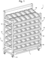
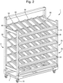
- the preferred embodiment of the present invention is a shelving system 1 suitable for vendor managed inventory (VMI) in which a plurality of shelves 70 each includes a plurality of lanes for holding storage bins 60.
- the system 1 includes a frame 5 including uprights 10 fixed on each corner of a base 5. Casters 15 are fixed to the lower corners of the base 7.
- a front cross member 20 and a rear cross member 30 are fitted to the uprights 10 for each shelf.
- Each lane is formed by a primary rail 40 and a secondary rail 50, both of which are mounted at the forward end to the front cross member 20 and at the rear end to the rear cross member 30.
- a plurality of pairs of primary and secondary rails 40, 50 are mounted to form a plurality of lanes.
- the primary rail 40 includes a support portion 415 and an upright guide portion 417
- the secondary rail 50 includes a support portion 515 and an upright guide portion 517.
- the bins 60 are supported on the support portions 415, 515 and guided to stay within the lane by the upright portions 417, 517.
- the front cross member 20 is positioned lower than the rear cross member 30 for each shelf 70 so that the lane slopes downwards towards the front.
- the top of the front cross member 20 is higher than the top the front end of the support portions 415, 515.
- a bin 60 is placed at the back of an empty lane it will slide down the support portions 415, 515 until the front of the bin 60 abuts the top of the front cross member 20. If a second bin 60 is subsequently placed at the back, it will slide forward until it abuts the first bin 60. If the first bin 60 is then removed, the second bin 60 will then slide forward.
- the primary and secondary rails are angled at substantially 18° so that the bins 60 slide forward under their own weight.
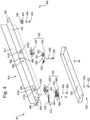
- each primary rail is an assembly that comprises an upper rail portion 410, a lower housing 420 and two sensors 700.
- the upper rail portion 410 includes the support portion 415 and the upright guide portion 417.
- the support portion 415 is provided with a sensor hole 4105 for each of the sensors 700, sensor mounting holes 4107 for mounting (part of) the sensors 700, a hole 448 for mounting a rear lug 440, a front mounting hole 480, holes 428 for mounting the lower housing 420, and circuit board mounting holes 468 for mounting printed circuit boards 450, 460.
- Each sensor 700 comprises a light emitter 451, a light receiver 452 and an interrupter assembly 430.
- the light emitter 451 and light receiver 452 of the front sensor 700 are provided on a front printed circuit board (PCB) 460, and the light emitter 451 and light receiver 452 of the rear sensor 700 are provided on a rear PCB 450.
- the front and rear sensor PCBs 450, 460 are fitted by means of spacers 457 (see Fig. 6 ), screws 458 and washers 459 to the bottom of the upper rail portion 410 using the circuit board mounting holes 468 at the front and rear.
- the front and rear PCBs 450, 460 are spaced apart from the bottom surface of the support portion 415 using the spacers 459, which may be formed integrally with the support portion 415 or fixed later. In this way, the light emitter 451 and light receiver 452 are provided between the PCB 450, 460 and the bottom surface of the support portion 415.
- the rear PCB 450 includes a connector 454 and the front PCB includes a connector 464, which allows the two PCBs to be connected by means of a cable 490.
- the front PCB includes a further connector 466, which allows it to be connected to a shelf PCB (to be described later) by means of a cable 470 and plug 475.
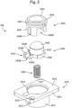
- each sensor 700 includes an interrupter assembly 430 (see Fig. 5 ) which includes a housing 4310, a coil spring 4320, an interrupter 4330 and a collar 4340.
- the housing 4310 includes a well 4312 and a flange 4314 provided around the upper end of the well 4312.
- the interrupter 4320 is held in the well 4312 by the collar 4340 with the coil spring 4320 disposed between the bottom of the well 4312 and the interrupter 4330 to bias the interrupter 4330 upwards away from the bottom of the well 4312 towards the collar 4340.
- a cylindrical projection (not shown) may be provided in the bottom of the well 4312 over which the spring 4320 may fit to locate and hold it in the well 4312.
- the interrupter 4330 includes a cylindrical main body 4333 with a domed top 4332. It also includes a projection 4334 at the bottom of the main body 4333.
- the projection 4334 includes a first lower portion 43342 adjacent the bottom of the main body 4333 and second upper portion 43348 extending from the top outer corner of the first lower portion 43342.
- the projection 4334 includes an inner upper notch 43344 above the first lower portion 43342 and adjacent the main body, and a lower outer notch 43346 below the second upper portion 43348.
- the interrupter 4320 also includes lower flanges 4336 extending outwards on either side of the projection 4334.
- the collar 4340 includes a lip 4344, which fits into a rim 4315 formed in the flange 4314 and surrounds the top of the well so that top of the lip 4344 is flush with the top 4316of the flange 4314.
- a cylindrical body 4346 projects downward from the lip 4344 of the collar 4340 and fits in the well 4312.
- the cylindrical body 4346 includes a slot 43464 corresponding to the projection 4334 of the interrupter 4330 and notches 43462 corresponding to the lower flanges 4336.
- a ring 4343 projects upwards above the lip 4344 and lies within the sensor hole 4105 when the assembly 430 is mounted to the bottom of the support portion 415. Mounting is carried out using screws and washers on a threaded stud (not shown) placed through the sensor mounting holes 4318 in the flange 4316 and corresponding holes 4107 in the support portion 415 such that the top 4316 of the flange 4314 abuts the lower surface of the support portion 415.
- the top 4343 of the ring 4342 is preferably flush or below the upper surface of the support portion 415.
- the abutment of the rim 4344 against the bottom of the support portion 415 holds the collar 4340 in place with the interrupter 4330 sandwiched between the collar 4340 and the housing 4310.
- the coil spring biases the interrupter main body 4330 upwards so the domed surface 4332 projects above the upper surface of the support portion 415.
- the interrupter main body 4330 can travel up and down, with the projection 4334 travelling in the slot 43464 and the lower flanges 4336 travelling in the notches 43462.
- the interrupter 4330 When a shelf bin 60 rests on the domed surface 4332, the interrupter 4330 is displaced downwards against the force of the coil spring 4320 and the outer upper portion 43348 of the projection 4334 is disposed between the emitter 451 and receiver 452 to block transmission of light. This signals that an item is present, which can be communicated to the corresponding shelf PCB 250, 260 (described later).
- the biasing force of the spring 4320 acts to move the interrupter 4330 upwards so light emitted from the emitter 451 is no longer blocked from the receiver. This signals that an item is not present, which can be communicated to the shelf PCB 250, 260.
- the lower housing 420 is fitted by means of spacers 421, screws 422 and washers 424 to bottom of the support portion 415 so that all the sensor components are enclosed by the support portion 415 and the housing 420 (apart from the domed surface 4332).
- the spacers 421 may be formed integrally with the support portion 415 or fixed later.
- the interrupter main body 4330 can travel 6 mm in the housing and will start to interrupt the beam after about 3 mm of travel (half the stroke). Note that the interrupter 4330 of the front sensor 700 has been omitted from Figs. 4 and 6 .
- the primary rail 40 also includes a rear mounting lug 440 fitted by means of screws 444 and washers 446 to the bottom of the support portion 415 using the rear lug hole 448.
- the rear mounting lug 440 comprises a foot 441 and a leg 442 having a smaller diameter than the foot 441.
- a screw is also provided as the front mounting lug, which is passed through the front mounting hole 480 and screwed into the front cross member 20.
- a washer may also be used.
- the secondary rail 50 includes a support portion 515 and an upright guide portion 517.
- the secondary rail 50 is oppositely handed to the primary rail 40, which is to say that the support portion 515 is provided on the opposite side of the upright guide portion 517 compared to the primary rail.
- the secondary rail 50 also includes a rear mounting lug 540 fitted by means of screws 544 and washers 546 to the bottom of the support portion 515 using the rear lug hole 548.
- the rear mounting lug 540 comprises a foot 541 and a leg 542 having a smaller diameter than the foot 541.
- a front mounting lug 510 is provided at the front end of the secondary rail 50 in the form of a cylindrical rod or dowel, which may have a chamfered, pointed or rounded end.
- the front cross member 20 is shown in Figs. 9 to 11 . As shown in Fig. 9 , it includes a bracket 210 on either side for mounting to corresponding frame uprights 10 and a front cover 220 which is hinged to the front cross member main body 240. As shown in Fig. 9 , the front cover 220 includes a window 230 through which light from LEDs 267, 268 provided behind the cover 220 can be seen. Preferably the window 230 is made of translucent material so that individual LEDs 267, 268 cannot themselves be seen and only the light they emit is visible.
- the front cross member main body 240 includes a front cross member front portion 241, which is substantially vertical, a front cross member upper portion 242, which is at an angle to the horizontal corresponding to the angle of the primary and secondary rails 40, 50, and a front cross member rear portion 243 which projects down a short way from a rear edge of the upper portion 242.
- a shelf controller 250 and a plurality of shelf expanders 260 are mounted to the front portion 241 of the front cross member main body 240 with screws 245.
- the shelf controller 250 and shelf expanders 260 are provided as PCBs, which are spaced apart from the front portion 241 using spacers 246, which may be formed integrally with the front cross member main body 240 or fixed later.
- the shelf expanders 260 are connected to the shelf controller 250 in a daisy chain using cabling 255 between adjacent shelf PCBs.
- the shelf controller PCB 250 and the shelf expander PCBs 260 all include a plurality of socket connectors 265, each for connecting to the plug connector 475 of the cabling 470 that is connected to the front PCB 460 of one of the primary rails 40.
- a primary rail 40 can be electronically connected to each of the sockets 265 of the shelf controller 250 and shelf expanders 260.
- Both the shelf controller PCB 250 and the shelf expander PCBs 260 include a pair of LEDs 267, 268 for each socket 265.
- the front cross member main body 240 also includes a cabling notch 270 provided in the front cross member upper portion 242 corresponding to each socket connector 265.
- the cabling notch 270 extends to and is partially formed in the rear portion 243.
- the front cross member main body 240 also has a primary rail front lug hole 280 corresponding to each cabling notch 270, and a plurality of secondary rail front lug holes 290, 295.
- a screw front mounting lug - not shown
- the front mounting lug 510 of a secondary rail 50 can be inserted into a secondary rail front lug hole 290, 295 to fit the secondary rail 50 to the front cross member 20.
- the rear cross members 30 are mounted to the rear uprights 10 of the frame 5. Mounting can be carried out in any suitable way, for example by providing brackets at the ends of each rear cross member 30 and/or brackets at appropriate places on the rear uprights 10.
- the rear cross member 30 includes a rear cross member front portion 341, which is substantially vertical, a rear cross member upper portion 342, which is at an angle to the horizontal corresponding to the angle of the primary and secondary rails 40, 50, and a rear cross member rear portion 343 which projects down from a rear edge of the upper portion 342.
- the rear cross member 30 includes a plurality of mounting notches 310 provided in the upper portion 342.
- Each mounting notch 310 extends forwards from a rear edge of the upper portion 342 and terminates before the front edge of the upper portion 342. Each mounting notch 310 also extends partially downwards into the rear cross member rear portion 343.
- the width of the mounting notch 310 at the rear edge of the upper portion 342 and in the rear portion 343, and the depth of the mounting notch 310 in the rear portion 343 is sized to allow the foot 441, 541 of the rear mounting lugs 440, 540 of the primary and secondary rails 40, 50 to be inserted into the mounting notch 310 so that the foot is disposed below the lower surface of the upper portion 342.
- the mounting notches 310 include a protrusion 340, which projects backwards from the front and centre of the mounting notch 310 to split the mounting notch into first and second mounting parts 390, 395 on either side of the protrusion 340.
- the protrusion 340 does not extend as far back as the rear portion 343 of the rear cross member 30.
- the width of the opening at the rear of each of the first and second mounting parts 390, 395 need not be as wide as the diameter of the foot 441, 541 of the primary and secondary rails 40, 50.
- each of the first and second mounting parts 390, 395 is wide enough to accommodate (at least part of) the leg 442, 542 for setting the position of the corresponding rail in the rear cross member 30.
- the respective rear mounting lug 440, 540 is slid forward into the mounting notch 310 until the leg 442, 542 abuts the forward end of the mounting notch 310 (or, where they are provided, either one of the first and second mounting parts) with the foot 441, 541 disposed below the upper portion 342. In this way, part of the upper portion 342 is sandwiched between support portion 415, 515 of the rail and the foot 441, 541 of the lug 440, 540 as shown in Fig.12 .
- the rear end of the rail 40, 50 is held in position in the rear cross member 30 but the front end is free to move up and down and to rotate left and right with the rear mounting lug 440, 540 acting as a pivot.
- the front end of the rail 40, 50 can then be swung into position for mounting to the front cross member 20.
- the front mounting hole 480 is aligned with the corresponding primary rail front lug hole 280 provided in the front cross member 240 and the two are fixed together with a screw (or any other suitable lug, such as a dowel or rod).
- the plug 475 of the cabling 470 attached to the front sensor PCB 450 is then plugged into the socket connector 265 corresponding to the primary rail front lug hole 280.
- the cabling 470 passes forward of the front of the primary rail 40 through the cabling slot 270, lies over the upper portion 242 of the front cross member main body 240 and bends downwards to plug into the corresponding socket connector 265. This avoids the cabling 470 being pinched between the support portion 415 of the primary rail 40 and the front cross member 20.
- the front mounting lug 510 is simply fitted into the corresponding one of the secondary rail front lug holes 290, 295 provided in the front cross member main body 240.
- front cover 220 When the front cover 220 is closed, it covers the stop portions 405, 505 provided at the front ends of the primary and secondary rails 40, 50. This prevents the front ends of the rails 40, 50 from being lifted away from the front cross member 20.
- the front cover is first opened.
- To remove the primary rail 40 it is a simple case of unplugging the cabling 470, unscrewing the screw acting as the front mounting lug, lifting the front end of the rail and sliding it backwards so the foot 441 slides out of the mounting notch 310.
- the primary and secondary rails 40, 50 can be mounted in pairs to form a lane between them.
- the width of the support portion 415 of the primary rail 40 is greater than the width of the support portion 515 of the secondary rail 50.
- the front mounting hole 480 is set off from the middle of the support portion 415 in the width direction towards the side of the upright guide portion 417, whereas the domed surface 4332 is set off to the other side.
- the front mounting lug 510 is in the middle of the width of the support portion 515 of the secondary rail 50.
- the width of the lane formed between the upright guide portions 417, 517 of the primary and secondary rails 40, 50 is greater than the distance between the front mounting hole 480 of the primary rail 40and the front mounting lug 510 of the secondary rail 50, and therefore greater than the distance between the corresponding primary rail front lug hole 280 and secondary rail front lug hole 290, 295 used to mount the rails to the front cross member 20.
- Figs. 16 to 18 show the pattern of the primary and secondary rail front lug holes 280, 290,295 and the cabling grooves 270 on the front cross member 20, and the corresponding pattern of the mounting notches 310, including the pairs of first and second mounting parts 390, 395 where provided, on the rear cross member 30.
- the mounting notches 310 including the pairs of first and second mounting parts 390, 395, allow mounting of a foot 441, 541 of either the primary rail 40 or the secondary rail 50 at positions A, B, C, D, E, F and G in which positions A, B and C are provided at the left hand side of the rear cross member 30, positions D and E are then formed by the pairs of first and second mounting parts 390, 395 being repeated at constant intervals moving from left to right all the way up to positions F and G at the right hand end of the rear cross member 30.
- a primary rail front lug hole 280 and a cabling notch is provided corresponding to positions A, B, C and all E. They are not provided at any position D, For G.
- a primary rail can be mounted at all positions A, B, C and E but not at any position D, For G.
- a secondary rail front lug hole 290 is provided at positions D and F and a secondary rail front lug hole 295 is provided at all positions B, C, E and G. This means that a secondary rail 50 can be mounted at all position B, C, D, E, F and G but not at position A.
- this pattern of the mounting features on the front cross member 20 and rear cross member 30 allows lanes of three spacings (in relative terms narrow, medium and wide) to be consistently formed across the width of a shelf 70.
- a narrow lane can be formed by positioning the adjacent secondary rail 50 in the adjacent position E (2).
- the distance between the rear mounting features (second mounting parts 395) in the rear cross member 30 is distance P.
- the width of the narrow lane will actually be wider than distance P due to the positioning of the respective upright guide portions 417, 517 of the primary and secondary rails 40 and 50 being positioned outside the front mounting hole 480 and the front mounting lug 510 respectively, and outside the rear mounting lugs 440, 540 respectively, in the lane width direction.
- the primary rail 40 of the adjacent lane to the right-hand side can be fitted at the next adjacent position E (3).
- a medium width lane can be formed by positioning the adjacent secondary rail in the next but one position E (3) - that is the second position E in the right-hand direction, with an intermediate position E (2) in between them.
- the width of the medium lane will be a distance P wider than the width of the narrow lane.
- the width of the medium lane will not be double the width of the narrow lane in view of the offset of the upright guide portions 417, 517 described above.
- the primary rail 40 of the adjacent lane to the right-hand side can be fitted at the next adjacent position E (4).
- a wide lane can be formed by positioning the adjacent secondary rail in the next but two position D (4) - that is the third position D in the right-hand direction, with two intermediate positions D (2 and 3) in between them.
- S is the distance between a position E (3, for example) and the next position D (4) to the right.
- the width of the wide lane will be a distance S wider than the width of the medium lane.
- the primary rail 40 of the adjacent lane to the right-hand side can be fitted at the next but one position E (5, not shown) since, in the present embodiment the combined offsets of the upright guide portions 417, 517 from the rear mounting lugs 440, 540 means there is not sufficient room to fit the next primary rail in the position E (4) directly adjacent to and to the right of the position D (4) to which the secondary rail is mounted. In other embodiments, the design of the mounting features and offset of the upright guide portions may make this possible.
- Fig. 18 also shows he distances P, Q and S as applied to the mounting features on the front cross member 20.
- each group of a cabling notch 270, a primary rail front lug hole 280, a secondary rail front lug hole 290 and a secondary rail front lug hole 295 is spaced apart from the adjacent group by the pitch P.
- the right hand secondary rail front lug hole 295 in one group (position E) is spaced apart from the left hand secondary rail front lug hole 290 of the adjacent group to the right (position D) by the distance S.
- position B is spaced a distance P away from position A
- position C is spaced a distance Q away from position A
- position D is spaced a distance R away from position A.
- a narrow lane can be formed by placing a secondary rail 50 at position B
- a medium lane can be formed by placing a secondary rail 50 at position C
- a wide lane can be formed by placing a secondary rail 50 at position D.
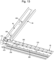
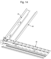
- Figs. 13-15 respectively show narrow, medium and wide lanes being formed in this way.
- the primary rail 40 for the next lane to the right can be fitted at the first position E.
- the primary rail 40 for the next lane to the right can be fitted at the second position E.
- a primary rail 40 at position B (that is, a primary rail front lug hole 280, a cabling notch 270 and a mounting notch 310 are provided at position B), in the present embodiment no connector 265 is provided in the shelf controller PCB 250 corresponding to position B. Thus, a primary rail 40 cannot be electronically connected to the frame 5 at this position.
- a connector 265 and associated circuitry may be provided at position B in a shelf PCB 250, 260.
- a secondary rail 50 is at position G, then a narrow lane is formed when a primary rail 40 is positioned at the rightmost position E, and a medium lane is formed when primary rail 40 is positioned at the position E second from the right.
- a secondary rail 50 is formed at position F, then a wide lane is formed if a primary rail is position at position E third from the right.
- the design of the mounting features and their patterning on the front cross member 20 and the rear cross member 30 allows the primary and secondary rails 40, 50 to be fitted to the frame 5 at different positions easily and quickly, so that shelves can be simply configured to have lanes of different widths.
- the shelf system of the present invention is therefore very easily configurable.
- P 63.5 mm
- Q 122 mm
- R 168.5 mm
- S 41.5 mm.
- each possible position of the primary shelf (positions A, C and E) is associated with a pair of LEDs 267, 268 on either the shelf controller PCB 250 or a shelf expander PCB 260.
- the position of the LEDs 267, 268 relative to a primary rail 40 that has been mounted is consistent irrespective of the actual position of the primary rail 40. This makes it possible always to signal a status of the lane associated with the primary rail 40 in a clear and consistent manner.
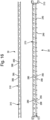
- FIGs. 19 and 20 show primary and secondary rails 40, 50 mounted to form a wide lane on the far left and a medium-width lane to the right of it).
- each LED 267 and each LED 268 is a multi-colour single device package with a red LED and a green LED on the same silicon, which allows the display of red ON, green ON or both ON (amber). They may also be controlled to flash green, red and amber in any combination of one, two or more and in any desired order and with any desired timing.
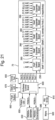
- Fig. 21 shows a schematic diagram of control circuitry of the shelving system 1.
- Each shelf 70 in the frame 5 includes a shelf control board 250 (also called shelf controller PCB) and one or more shelf expander boards 260 (also called shelf expander PCB), which may be collectively termed shelf boards 250, 260.
- shelf expander PCB also called shelf expander PCB
- each shelf board 250, 260 in each shelf are interconnected by an expansion interface 255, which is daisy-chained through each shelf board 250, 260.
- Each shelf board 250, 260 includes a microcontroller (not shown).
- each sensor PCB 450, 460 may include a microcontroller, although this is not essential.
- each shelf control board 250 includes connectors 265 for two lanes (two primary rails) and each shelf expander board 260 includes connectors 265 for five lanes (five primary rails), although it will be apparent that not all these connectors 265 need be used in a particular configuration of a shelf 70.
- each shelf 70 includes connectors 265 for 22 primary rails (and hence lanes).
- the circuitry includes a frame controller (frame control board) 600 which is mounted at any suitable location to the frame 5.
- frame controller 600 includes six ports for connecting to their respective shelf control boards 250.
- the connectors 265 for the expander boards 260 are 6-way ribbon cables as are the daisy chain cables 255, although other connections such as RJ45 ports could be used.
- the frame control board 600 is connected to mains power 620 via a power supply unit PSU 610.
- the frame control board 600 also enables internet connection via PICBUS+ upstream and downstream modules 630, 640 to multiple frames 5 in the shelving system 1.
- the frame control board 600 is connected to one or more frame LEDs 650 and to one or more status LEDs 670 to display the status of the frame 5 as a whole.
- the frame controller 600 can be individually controlled via a computer (not shown) through serial port 680, which acts as a local terminal, and provides a local diagnostic and configuration port for a technician to interrogate the shelving system 1 with a dumb terminal.
- the frame controller 600 may also be provided with a push button 660 for example for a test mode.
- the frame control board 600 also includes a plurality of jumpers for setting the frame number (although a frame address could be stored in a non-volatile memory as well or instead).
- the frame controller 600 can communicate directly with the shelf boards 250 in parallel, and can determine which shelf is being addressed based on the port number.
- the frame controller 600 is capable of current limiting and fault monitoring for each of the shelves 70. If any port tries to draw an amount of current above a predetermined threshold, the frame controller 600 can shut down the corresponding shelf 70 and signal an alarm.
- each shelf control board 250 monitors and controls power to all shelf expander boards 260, allowing individual expander boards to be shut down if a fault arises.
- each shelf board 250, 260 could be capable of current limiting and fault monitoring for the next shelf expander board 260 in the daisy chain. If a downstream port in the daisy chain were to draw an amount of current above another predetermined threshold, the shelf control board 250 would shut down the lanes associated with the shelf expander board 260 and signal an alarm.
- each shelf board 250, 260 is capable of current limiting and fault monitoring for all the lane connectors 265 together.
- a shelf expander board 260 and all its lanes can be shut down, with a fault in one lane in the group of lanes on that shelf expander board 260.
- the isolation of a group of lanes on a shelf expander board 260 is autonomous and will only be reported upwards when polled. Similar considerations apply in respect of the shelf control board 250.
- each is capable of current limiting and fault monitoring for each of the lane connectors 265 separately.
- the shelf board 250, 260 can shut down the sensors 700 and signal an alarm. In preferred embodiments it may also be possible to shut down a single sensor 700 and raise an alarm in a similar way using control on the separate sensor 700 boards 450, 460. Alternatively, if a primary rail 40 tries to draw too much current, this may be reported to the shelf control board 250, which may shut down all the lanes associated with the board to which the primary rail 40 is connected.
- each shelf board may assign or include information relating to the lane numbers it is associated with, as shown in Fig.21 .
- the shelf control board 250 since the shelf control board 250 is always connected first in the shelf 70, it knows that the respective socket connectors 265 are for lanes 1 and 2.
- Each of the shelf expander boards 260 is programmed to receive an instruction from the preceding shelf board 250, 260 that it is board number n, and to pass on to the next shelf expander board 260 that the next shelf expander board 260 is board number n+1.
- n is a soft parameter passed to the boards or programmed in a non-volatile EEPROM on the respective boards.
- the shelf expander boards are consecutively numbered as 1 to max (1-4 in the present embodiment).
- the lane numbers on the n th shelf expander board 260 are 5(n-1) + 3, 5(n-1) + 4, 5(n-1) + 5, 5(n-1) + 6 and 5(n-1) + 7.
- shelf expander boards 260 there is no requirement to use four shelf expander boards 260, to provide five lanes on each shelf expander board 260 or to provide two lanes on the shelf control board 250, and any suitable values for n, x, and z may be chosen.
- the shelf control board 250 and the shelf expander boards 260 can send back to the frame control board 600 information about the status of the two sensors 700 on each of their respective lanes, along with the lane number to which that status applies.
- the frame control board 600 can determine for each lane whether a shelf bin 60 is on each of the sensors 700 in the lane and to control the shelf boards 250, 260 to illuminate the LEDs 267, 268 corresponding to a lane based on the status of that lane.
- the frame control board 600 is also able to place an order for stock for any lane using a software interface with an external stock control system or to indicate an order is required to be placed depending on the specific implementation, and to receive a status of the stock order from the stock control system, which can be connected via the PICBUS+ control modules 630, 640 and/or the serial port 680.
- the shelf control board 250 is provided with a common sync clock, signals of which are provided to each of the shelf expander boards 260 on the shelf 70. In this way, all the LEDs 267, 268 can be made to flash synchronously across the shelf 70.
- the frame control board 600 periodically sends a data packet to all shelf control boards 250 simultaneously to reset their respective sync clocks. In this way, all the LEDs 267, 268 across the frame 5 can be made to flash together.
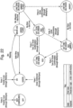
- FIG. 22 An exemplary use of the shelving system 1 of the embodiment will now be described with the aid of the state diagram shown in Fig. 22 , in which solid lines show changes in state resulting from actions of a user of the shelving system 1 and dashed lines show changes in state resulting from interactions with the external stock control system.
- the state diagram represents the changes in state of a lane and how the LEDs 267, 268 for that lane are controlled.
- the lane is not configured and the LEDs 267, 268 are switched off. This may be, for example, because there has been an overcurrent detected for that lane (primary rail 40), for the block of lanes on the shelf board 250, 260 with which the LEDs 267, 268 are associated, or for the shelf 70 or frame 5 as a whole.
- both sensors 700 indicate that a shelf bin 60 is present - in other words, there are two bins 60 on the lane: a front, lower bin (first bin) and a rear, upper bin (second bin).
- the bins 60 are both assumed to contain predetermined stock items, for example, screws, washers, bolts, components or other parts used in a manufacturing process. Consequently, it is assumed that there is sufficient stock of the items in the lane and the LEDs 267, 268 are switched to display a solid green light (green on).
- each lane may include different types of item, or that some or all of the lanes may include the same stock item.
- a record of which items are in which lanes may be stored in any of the corresponding shelf boards 250, 260 with which the lane is associated, in the shelf control board 250 for the shelf 70 in which the lane is provided, the frame control board 600 or even the external stock control system.
- a record may also be kept of the predetermined maximum number of stock items in each bin when it is first filled/refilled.
- the two sensors 700 of the lane are polled at a predetermined interval. If the user removes either bin 60 from the lane, the sensors 700 indicate that there is a bin missing and the lane moves to state 2.
- the LEDs 267, 268 flash green (green flash) to indicate a bin is missing. If the user replaces the bin 60 the right way around within a predetermined period, the lane returns to state 1 (green on).
- the user picks items out of the first bin 60 until they are exhausted.
- the user removes it from the shelf 70 and the second bin 60 slides forward to replace it, due to the angling of the first and second rails 40, 50.
- the user is then able to take stock from the second bin 60, which is now at the front.
- the user can either leave the first bin 60 to the side or he can place it back in the lane behind the second bin, but upside down.
- the lanes and bins 60 are sized such that if a bin 60 is placed upside down at the back of the lane, it does not depress the domed surface 4332 of the rear sensor 700.
- the sensors 700 initially indicate that there is a bin 60 missing and the lane moves to state 2 (green flash) but when the bin 60 is not replaced within the predetermined time, or is replaced upside down, the lane moves to state 3 (amber flash).
- state 3 the system 1 determines that the lane is low on stock and places an order with the external stock control system to fill the bin 60 (or for a full bin 60) for that lane.
- the lane Upon receiving confirmation of the order, the lane is moved to state 4 (amber on) to indicate that the lane is low on stock but one bin 60 of stock has been ordered. If the stock is received (the order is delivered and confirmed by the user with the external stock system) and the full bin 60 is placed in the lane, the lane is moved back to state 1.
- the lane moves to state 6. This means there are no bins 60 in the lane so the lane is considered to be out of stock, with one bin 60 of stock being on order.
- the LEDs 267, 268 alternate red and amber on.
- the system 1 places a further order for stock and once this is confirmed the lane moves to state 7 (red on) in which stock is out but two bins 60 of stock are on order.
- state 3 if before the order is placed and confirmed, the second bin 60 is also removed and it is detected that there are no bins 60 for longer than a predetermined amount of time, the lane moves to state 5 (red flash). In state 5, there are no bins 60 in the lane and the lane is considered to be out of stock, without any stock being on order.
- the system then places an order for two bins 60 of stock. If only one is confirmed, the lane moves to state 6, as described above, but if both are confirmed, the lane moves to state 7, as described above.
- states, predetermined times and LED signals can be configured in any appropriate manner.
- the states in the state diagram are predetermined and during set up the user can select from any of a fixed number of values for each variable, such as the predetermined time required to be passed before moving to another state, or how the LEDs display.
- the bin 60 missing times needed to transition between states can take values anywhere between 5 seconds and 1 day. Different bin 60 missing times can be selected for transitioning between different states. The values available to select for the different bin 60 missing times may be the same or different.
- the present invention provides an easily configurable shelf system 1 in which shelf bins 60 of varying widths can be guided down lanes of corresponding width. This allows an optimum layout of bins 60 in a shelf 70 and in a frame 5, in view of the different types of stock item and the size of the frame 5. Moreover, because each lane is formed of an intelligent primary rail 40 in which the sensing electronics are provided and a dumb secondary rail 50 without electronics, assembly and reconfiguration of the shelf system is easier.
- the primary and secondary rails 40, 50 each include a supporting portion 415, 515 which support the weight of the bins 60, it is not necessary to include a separate supporting plane or other surface on which the bins 60 can slide. This reduces the weight of the system 1, makes the system 1 easier to assemble and, after manufacturing, to pack it for transport and subsequent assembly.
- the sensors 700 are provided in the supporting portion 415 of the primary rail 40 it is an easy matter to sense the presence of the bins 60 and to move the sensors 700 when the lanes have been reconfigured. It also makes it easy to sense the presence of a bin 60 when it is the right way around and to sense a bin 60 missing even when it is placed back in the lane upside down. This type of sensing is made considerably easier by the fact that the sensors 700 work by depressing the domed surfaces 4332.
- the sensor 700 of this embodiment is particularly advantageous for several reasons. These include that, since the front and rear sensor PCBs 450, 460 are mounted to the primary rail 40 separately from the interrupter assemblies 430, the moving parts of the sensor 700 are isolated from the electrical components, which makes the sensors 700 particularly robust. As there are no electrical moving parts, the life of the switch is unaffected by movement of electrical connections, which would be likely to cause failure over repeated use of another sensor switch. In addition, oxidation of the conductive parts of the sensor do not affect whether a circuit is made or broken, further increasing the life of the sensor 700.
- the interrupter housing 4310, interrupter 4330 and collar 4340 can all be cheaply made of hard-wearing, moulded plastic such as ABS, improving cost of manufacturing and longevity of the sensor 700.
- a further advantage is that the different components of the sensor 700 can be easily mounted to the primary rail, improving ease of manufacture.
- the senor 700 of the present invention is extremely robust, as well as cheap to make and easy to fit.
- the pattern of the mounting components on the front cross member 20 and the rear cross member 30 it is easy to configure lanes of different widths, where the widths of the lanes are not multiple integers of each other. Moreover, the pattern used allows both primary rails 40 and secondary rails 50 to be mounted in the same place, depending on the desired lane configuration, further improving space efficiency and increasing configurability.
- shelf control board 250 and the shelf expander boards 260 makes it easier to manufacture front cross members 20 and hence shelves of different lengths with different numbers of positions for the primary rail 40 whilst maintaining all the advantages of configurability.
- the only change to the components required for a longer shelf is to provide a longer front cross member main body 240, a longer front cross member cover 220 and a longer rear cross member 30. More of the same primary and secondary rails 40, 50 can be supplied for the longer shelf, and additional shelf expander PCBs can be fitted to the front cross member main body 240. It also makes it easy to swap out individual components in case of fault with a minimum degree of cost in terms both of components and labour. Similar considerations apply in the use of different sensor 700 circuit boards 450, 460 for the respective sensors 700.
- each front cross member 20 and each primary rail 40 is provided as a selfcontained unit, the system 1 can be easily assembled and configured with varying numbers of shelves 70.
- the frame 5 it would be possible to configure the frame 5 with only five shelves instead of six, and no change in programming or electronic set up would be required.
- Manufacturing and assembly of the system 1 are also very easy. During manufacturing, it is only necessary to connect the sensor PCBs 450, 460 in the primary rail 40 to each other, and the shelf boards 250, 260 in the front cross member 20 to one another. This means that the primary rail 40 and the front cross member 20 can be shipped as preassembled components along with the rest of the system 1. During assembly, it is only necessary to connect each primary rail 40 into a corresponding connector 265 of a front cross member 20, and then to connect each shelf control board 250 into the frame control board 600. It is then possible to determine automatically which shelves 70 have been connected and where primary rails 40 have been connected along a shelf, and hence which lanes exist and where.
- the system 1 can be shipped in flat pack form and assembled quickly and easily on site with the desired configuration.
- a frame control board 600 connected to the shelf control board 250 and hence to the shelf expander boards 260 gives rise to monitoring and control of each of the bins 60 in each of the lanes.
- By connecting the frame control board 600 to an external stock control system it is possible to order replacement stock automatically and to signal to a user of the system 1 not only the states of stock high, stock low and stock out, but also the order status using the LEDs 267, 268.
- the electrical configuration is also advantageous. In particular, it is possible to keep a track of the status of each lane without a complicated addressing scheme. Rather each lane number on each shelf can be allocated automatically. In addition, by using current limiting in the manner discussed above, it is possible for one lane, one block of lanes or one shelf to malfunction without killing other lanes, blocks or shelves. In addition, it is possible to tell which lane, block or shelf has malfunctioned.
- each of the shelf boards 250, 260 it is possible to configure each of the shelf boards 250, 260 to scroll illumination of green, amber and red on power up so that faulty boards/lanes can be spotted.
- the expression "LED” includes a single LED or an LED package including LEDs of two or more colours.
- two LED packages 267 and 268 are provided in the present embodiment it is possible to provide a single LED package or more than two LED packages.
- the LEDs will be switched on most of the time, the use of one or more extra LED packages also builds in redundancy. If both LED packages are lit at the same time, even if one fails the other can be expected to continue working. Alternatively, one of the LED packages can be used until it fails after which another LED package can take its place.
- any suitable indicator can be used, including lights, mechanical flaps and so on.
- any suitable colours or combinations of colours can be used whether the indicators are LEDs, lights, flaps, switches or another type of indicator. It is not necessary to use colours at all.
- shelf control boards 250 are connected in parallel to different ports on the frame control board 600.
- serial, multi-drop communications with each of the shelf control boards 250 being connected to the same bus and including an address (for example, stored in a memory or hardwired in the form of jumpers).
- the whole of the bottom of the bins 60 is flat. This makes it easier to ensure that the presence of the bins 60 is properly detected in the lanes since the bottom of a bin 60 will depress the domed surface 4332 of a sensor 700 even if the lane is wider than the bin 60 and there is some play allowed for the bin 60 to move in the width direction in the lane.
- other types of bin 60 are possible, such as linbins in which the bin 60 typically includes rails on the bottom. So long as the rails are supported by the support portions 415, 515 of the primary and secondary rails 40, 50 and will depress the domed surface 4332, there is no problem.
- bins 60 of the sizes described above it is not necessary to use bins 60 of the sizes described above, and any suitable size or sizes can be used.
- Another example of a different type of bin 60 that could be used is a BITO ® bin in place of or at the same time as the AKRO-MILS ® type (preferably in different lanes or shelves 70).
- Different types of bin 60 are easily accommodated in the present invention, for example by providing a different secondary rail 50 which accommodates the variance in bin width but gives the ability to maintain the same location pitch across the front and rear members.
- the secondary rails 50 will have mounting features in the same positions as the original secondary rails 50 but the width of the support portion 515 and/or the position of the upright guide portion 517 relative to the mounting features may be adjusted as appropriate.
- modified primary rails 40 may be used.
- the preferred sensor seeks to sense an adjacent surface of the bins 60 and, or instead, preferably also senses a continuous face of the bins 60 and does not sense an open face.
- the flat, bottom surface of the bin 60 can be considered to be a continuous face and the opening at the top can be considered to be an open face.
- the continuous face could be a surface along the side of the bin 60 or a surface along a bottom rail, whereas the open face can be any opening, for example one that is large enough to place and remove the desired items in and from the bin 60.
- the mounting notches 310 in the rear cross member 30 need not extend to the rear surface 343 so long as the feet 441, 541 can be positioned through the mounting notches 310 and the legs made to abut the notch 310.
- the notches 310 may simply be circles or teardrop-shaped holes in the upper surface 342, which the feet will fit into.
- the protrusion 340 it is also not necessary to use the protrusion 340 to split the mounting notches 310 into separate mounting parts 390, 395 - different mounting notches can be used instead. Conversely any or all notches 310 can be split into different mounting parts using protrusions 340.
- the mounting features on different ends of the primary and secondary rails 40, 50 could be switched, and to switch the mounting features between the front cross member 20 and the rear cross member 30.
- the mounting features on the front and rear cross members 20, 30 could be provided on the primary and secondary rails 40, 50 and vice versa.
- the lugs could be on the cross members and slots/holes on the rails.
- the sensors 700 of the present embodiment use a light emitter 451 and a light receiver 452. However, they need not emit light, or at least visible light.
- other types of sensor 700 may be used, for example a leaf spring that is depressed by a bin 60 to make a circuit and so detect the presence of the bin 60. It is not essential to provide the sensor 700 with a domed surface 4334 and other shapes are possible, including ramps which slope forwards and/or backwards along the lane.
- Any suitable biasing means may be used in place of the coil spring 4320.
- the sensors 700 are not essential to provide the sensors 700 on the support portion 415. Instead, they could be provided on the upright guide portion 417, although in this case it may be difficult to reliably sense the presence bins 60 with a draught (in other words, where the bottom of the bin 60 is narrower than the top) and to distinguish between bins 60 that are the right way around and upside down.
- a lane may include three or more sensors 700 for three or more bins 60.
- 'front', 'back', 'rear', 'upper', 'top', 'over', 'lower', 'bottom', 'under' and like terms are relative terms and are not intended to be limiting unless otherwise stated. It is not necessary for the cross members 20, 30 to be provided right at the front and back of the frame 5, and the primary and/or secondary rails 40, 50 can overhang them both at the front and the rear. It is also not necessary to provide separate front and rear cross members 20, 30 and, for example, they can be formed of a single plate.
- At least one LED is preferably provided corresponding to each position of primary rail, however even this is not essential.
- PCBs are used.
- any type of board and connector may be used for the sensor, shelf control, shelf expander and frame control boards (450, 460, 250, 260, 600).
- the sensor boards 450, 460 could be individually connected to the shelf boards 250, 260 instead of being daisy-chained.
- the shelf expander boards 260 could be individually connected to the shelf control board 250 instead of being daisy-chained.
- Both or all sensors 700 could use a single sensor board, and a single shelf board could also be provided in place of multiple shelf boards.
- there may be any number of lanes associated with a shelf board 250, 260 for example by varying the number of connectors 265) and there may be any number of shelf boards (including one or none).
- the primary rail 40 is attached using a screwdriver and the secondary rail 50 is attached without using any tools.
- either or both rails 40, 50 can be attached without using tools, or by using a screwdriver or any other appropriate tool.
- the system is shipped for assembly on site, but with the primary rails 40 and the front cross member pre-assembled.
- the state machine shown in Fig. 22 can be extended or otherwise varied with different fault states and actions. For example, where a replacement bin 60 has been delivered in state 6 (out, one on order), the state may move to state 3 (low, zero on order). Similarly, where a replacement bin 60 has been delivered in state 7 (out, two on order), the state may move to state 4 (low, one on order). Again, where a replacement bin 60 has been delivered in state 4 (low, one on order), the state may move to state 1 (OK).
- State 0 (not configured) may also occur where the system is powering up or has recovered from a hardware error and is waiting for the external system to set the state. Additional states may also be included, for example state 10 - error, divider not fitted; state 11 - error, divider broken; state 12 - error, lane fault; state 13 - error, shelf expander board fault; state 14 - error, shelf fault.
- the state machine may be moved to and from these states by action of the software and/or hardware.
Landscapes
- Engineering & Computer Science (AREA)
- Mechanical Engineering (AREA)
- Warehouses Or Storage Devices (AREA)
Description
- The present invention relates to a shelving system, which is preferably suitable for stock control and vendor-managed inventory (VMI).
- Two bin kanban systems for stock control in a manufacturing environment are known. In existing systems, a shelf is provided with two bins for a stock item. The two bins are placed one behind the other on a pair of sloping, permanently fixed rails, which form a lane. A plurality of lanes is provided, each for holding a pair of bins. A user picks stock from the front bin. When the bin is empty, he removes it and draws the bin behind it to the front. The empty bin can be stacked in a pile to the side of the rack, or turned upside down and placed at the back of the lane.
- In some known systems, a mechanical switch senses that a bin has been removed and switches on/off an LED at the front to indicate that stock replenishment is required. Such systems have several drawbacks, including that they cannot be easily assembled or reconfigured to operate with bins of different sizes. Examples of known shelf systems are disclosed in
US 2017/202369 A1 ,US 2017/220987 A1 ,US 2005/168345 A1 ,US 2014/124463 A1 ,WO 2014/107462 A1 ,EP 1 473 529 A1 ,US 2013/153524 A1 andWO 2017/106764 A1 . - According to the present invention, there is provided a shelf system as set out in the appended claims.
- Embodiments of the invention will now be described by way of example only with reference to the accompanying drawings in which:
-
Fig. 1 is a perspective view of a shelving system according to an embodiment of the present invention; -
Fig. 2 is a perspective view of the shelving system inFig. 1 in which the storage bins have been removed; -
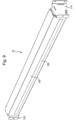
Fig. 3 is a perspective view of a primary rail of the embodiment; -
Fig. 4 is an exploded perspective view of the primary rail; -
Fig. 5 is an exploded view of an interrupter and housing of a sensor according to an aspect of the invention; -
Fig. 6 is perspective view of the lower components of the primary rail; -
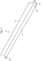
Fig. 7 is a perspective view of a secondary rail of the embodiment; -
Fig. 8 is an exploded perspective view of the secondary rail; -
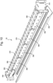
Fig. 9 is a perspective view of a front cross member of the embodiment; -
Fig. 10 is a perspective view of the front cross member in which the cover has been opened; -
Fig. 11 is an enlarged view of a portion of the front cross member illustrated inFig. 10 ; -
Fig. 12 is a perspective rear view of the shelving system and an enlarged view of part of a rear cross member with a primary rail and a secondary rail mounted to it; -
Fig. 13 is a partial perspective view of a corner of a shelf in the embodiment in which primary and secondary rails are mounted to form a narrow lane; -
Fig. 14 is a partial perspective view of a corner of a shelf in the embodiment in which primary and secondary rails are mounted to form a medium width lane; -
Fig. 15 is a partial perspective view of a corner of a shelf in the embodiment in which primary and secondary rails are mounted to form a wide lane; -
Fig. 16 shows a plan view of the front and rear cross members; -
Fig. 17 is an enlarged view of part of the plan view ofFig. 16 ; -
Fig. 18 is an enlarged view of another part of the plan view ofFig. 16 ; -
Fig. 19 is a front elevation of the front cross member with primary and secondary rails mounted to it; -
Fig. 20 is an enlarged view of part of the front elevation ofFig. 19 ; -
Fig. 21 is a schematic view of the control circuitry of the shelving system; and -
Fig. 22 is a state machine diagram of the operation of the shelving system. - As shown in
Figs. 1 and2 , the preferred embodiment of the present invention is ashelving system 1 suitable for vendor managed inventory (VMI) in which a plurality ofshelves 70 each includes a plurality of lanes for holdingstorage bins 60. Thesystem 1 includes aframe 5 includinguprights 10 fixed on each corner of abase 5.Casters 15 are fixed to the lower corners of thebase 7. Afront cross member 20 and arear cross member 30 are fitted to theuprights 10 for each shelf. - Each lane is formed by a
primary rail 40 and asecondary rail 50, both of which are mounted at the forward end to thefront cross member 20 and at the rear end to therear cross member 30. A plurality of pairs of primary andsecondary rails - As shown in
Figs. 3 to 8 , theprimary rail 40 includes asupport portion 415 and anupright guide portion 417, and thesecondary rail 50 includes asupport portion 515 and anupright guide portion 517. Thebins 60 are supported on thesupport portions upright portions front cross member 20 is positioned lower than therear cross member 30 for eachshelf 70 so that the lane slopes downwards towards the front. The top of thefront cross member 20 is higher than the top the front end of thesupport portions bin 60 is placed at the back of an empty lane it will slide down thesupport portions bin 60 abuts the top of thefront cross member 20. If asecond bin 60 is subsequently placed at the back, it will slide forward until it abuts thefirst bin 60. If thefirst bin 60 is then removed, thesecond bin 60 will then slide forward. Preferably, the primary and secondary rails are angled at substantially 18° so that thebins 60 slide forward under their own weight. - As shown in
Figs. 3 to 6 , each primary rail is an assembly that comprises anupper rail portion 410, alower housing 420 and twosensors 700. Theupper rail portion 410 includes thesupport portion 415 and theupright guide portion 417. Thesupport portion 415 is provided with asensor hole 4105 for each of thesensors 700,sensor mounting holes 4107 for mounting (part of) thesensors 700, ahole 448 for mounting arear lug 440, afront mounting hole 480,holes 428 for mounting thelower housing 420, and circuitboard mounting holes 468 for mounting printedcircuit boards - Each
sensor 700 comprises alight emitter 451, alight receiver 452 and aninterrupter assembly 430. Thelight emitter 451 andlight receiver 452 of thefront sensor 700 are provided on a front printed circuit board (PCB) 460, and thelight emitter 451 andlight receiver 452 of therear sensor 700 are provided on arear PCB 450. The front andrear sensor PCBs Fig. 6 ),screws 458 andwashers 459 to the bottom of theupper rail portion 410 using the circuitboard mounting holes 468 at the front and rear. The front andrear PCBs support portion 415 using thespacers 459, which may be formed integrally with thesupport portion 415 or fixed later. In this way, thelight emitter 451 andlight receiver 452 are provided between thePCB support portion 415. - The
rear PCB 450 includes aconnector 454 and the front PCB includes aconnector 464, which allows the two PCBs to be connected by means of acable 490. In addition, the front PCB includes afurther connector 466, which allows it to be connected to a shelf PCB (to be described later) by means of acable 470 andplug 475. - In addition, each
sensor 700 includes an interrupter assembly 430 (seeFig. 5 ) which includes ahousing 4310, acoil spring 4320, aninterrupter 4330 and acollar 4340. Thehousing 4310 includes a well 4312 and aflange 4314 provided around the upper end of the well 4312. Theinterrupter 4320 is held in the well 4312 by thecollar 4340 with thecoil spring 4320 disposed between the bottom of the well 4312 and theinterrupter 4330 to bias theinterrupter 4330 upwards away from the bottom of the well 4312 towards thecollar 4340. A cylindrical projection (not shown) may be provided in the bottom of the well 4312 over which thespring 4320 may fit to locate and hold it in thewell 4312. - The
interrupter 4330 includes a cylindricalmain body 4333 with a domed top 4332. It also includes aprojection 4334 at the bottom of themain body 4333. Theprojection 4334 includes a firstlower portion 43342 adjacent the bottom of themain body 4333 and secondupper portion 43348 extending from the top outer corner of the firstlower portion 43342. Thus, theprojection 4334 includes an innerupper notch 43344 above the firstlower portion 43342 and adjacent the main body, and a lowerouter notch 43346 below the secondupper portion 43348. Theinterrupter 4320 also includeslower flanges 4336 extending outwards on either side of theprojection 4334. - The
collar 4340 includes alip 4344, which fits into arim 4315 formed in theflange 4314 and surrounds the top of the well so that top of thelip 4344 is flush with the top 4316of theflange 4314. Acylindrical body 4346 projects downward from thelip 4344 of thecollar 4340 and fits in thewell 4312. Thecylindrical body 4346 includes aslot 43464 corresponding to theprojection 4334 of theinterrupter 4330 andnotches 43462 corresponding to thelower flanges 4336. - A
ring 4343 projects upwards above thelip 4344 and lies within thesensor hole 4105 when theassembly 430 is mounted to the bottom of thesupport portion 415. Mounting is carried out using screws and washers on a threaded stud (not shown) placed through thesensor mounting holes 4318 in theflange 4316 and correspondingholes 4107 in thesupport portion 415 such that the top 4316 of theflange 4314 abuts the lower surface of thesupport portion 415. The top 4343 of thering 4342 is preferably flush or below the upper surface of thesupport portion 415. - When the
interrupter assembly 430 is mounted to the bottom of thesupport portion 415 of theprimary rail 40, the abutment of therim 4344 against the bottom of thesupport portion 415 holds thecollar 4340 in place with theinterrupter 4330 sandwiched between thecollar 4340 and thehousing 4310. The coil spring biases the interruptermain body 4330 upwards so thedomed surface 4332 projects above the upper surface of thesupport portion 415. The interruptermain body 4330 can travel up and down, with theprojection 4334 travelling in theslot 43464 and thelower flanges 4336 travelling in thenotches 43462. Upwards movement of the interruptermain body 4330 upwards is limited by abutment of theflanges 4336 with the tops of theslots 43462 and optionally by abutment of the top of the lowerinner portion 43342 of theprojection 4334 with the top of theslot 43464. - When a
shelf bin 60 rests on thedomed surface 4332, theinterrupter 4330 is displaced downwards against the force of thecoil spring 4320 and the outerupper portion 43348 of theprojection 4334 is disposed between theemitter 451 andreceiver 452 to block transmission of light. This signals that an item is present, which can be communicated to thecorresponding shelf PCB 250, 260 (described later). - When the item is removed from the
domed surface 4332, the biasing force of thespring 4320 acts to move theinterrupter 4330 upwards so light emitted from theemitter 451 is no longer blocked from the receiver. This signals that an item is not present, which can be communicated to theshelf PCB - Once the front and
rear sensor PCBs interrupter assemblies 430 have been mounted to the lower surface of thesupport portion 415 of theprimary rail 40 and connected to one another, thelower housing 420 is fitted by means ofspacers 421,screws 422 andwashers 424 to bottom of thesupport portion 415 so that all the sensor components are enclosed by thesupport portion 415 and the housing 420 (apart from the domed surface 4332). Thespacers 421 may be formed integrally with thesupport portion 415 or fixed later. - In a preferred embodiment, the interrupter
main body 4330 can travel 6 mm in the housing and will start to interrupt the beam after about 3 mm of travel (half the stroke). Note that theinterrupter 4330 of thefront sensor 700 has been omitted fromFigs. 4 and6 . - The
primary rail 40 also includes arear mounting lug 440 fitted by means ofscrews 444 andwashers 446 to the bottom of thesupport portion 415 using therear lug hole 448. Therear mounting lug 440 comprises afoot 441 and aleg 442 having a smaller diameter than thefoot 441. - Although not shown, a screw is also provided as the front mounting lug, which is passed through the front mounting
hole 480 and screwed into thefront cross member 20. A washer may also be used. - As previously discussed and shown in
Figs. 7 and8 , thesecondary rail 50 includes asupport portion 515 and anupright guide portion 517. Thesecondary rail 50 is oppositely handed to theprimary rail 40, which is to say that thesupport portion 515 is provided on the opposite side of theupright guide portion 517 compared to the primary rail. Thesecondary rail 50 also includes arear mounting lug 540 fitted by means ofscrews 544 andwashers 546 to the bottom of thesupport portion 515 using therear lug hole 548. Therear mounting lug 540 comprises afoot 541 and aleg 542 having a smaller diameter than thefoot 541. In addition, afront mounting lug 510 is provided at the front end of thesecondary rail 50 in the form of a cylindrical rod or dowel, which may have a chamfered, pointed or rounded end. - The
front cross member 20 is shown inFigs. 9 to 11 . As shown inFig. 9 , it includes abracket 210 on either side for mounting to correspondingframe uprights 10 and afront cover 220 which is hinged to the front cross membermain body 240. As shown inFig. 9 , thefront cover 220 includes awindow 230 through which light fromLEDs cover 220 can be seen. Preferably thewindow 230 is made of translucent material so thatindividual LEDs - The front cross member
main body 240 includes a front crossmember front portion 241, which is substantially vertical, a front cross memberupper portion 242, which is at an angle to the horizontal corresponding to the angle of the primary andsecondary rails rear portion 243 which projects down a short way from a rear edge of theupper portion 242. Behind thefront cover 220, ashelf controller 250 and a plurality ofshelf expanders 260 are mounted to thefront portion 241 of the front cross membermain body 240 withscrews 245. In the present embodiment, theshelf controller 250 andshelf expanders 260 are provided as PCBs, which are spaced apart from thefront portion 241 usingspacers 246, which may be formed integrally with the front cross membermain body 240 or fixed later. The shelf expanders 260 are connected to theshelf controller 250 in a daisychain using cabling 255 between adjacent shelf PCBs. - The
shelf controller PCB 250 and theshelf expander PCBs 260 all include a plurality ofsocket connectors 265, each for connecting to theplug connector 475 of thecabling 470 that is connected to thefront PCB 460 of one of the primary rails 40. In other words, aprimary rail 40 can be electronically connected to each of thesockets 265 of theshelf controller 250 andshelf expanders 260. Both theshelf controller PCB 250 and theshelf expander PCBs 260 include a pair ofLEDs socket 265. - The front cross member
main body 240 also includes acabling notch 270 provided in the front cross memberupper portion 242 corresponding to eachsocket connector 265. Thecabling notch 270 extends to and is partially formed in therear portion 243. The front cross membermain body 240 also has a primary railfront lug hole 280 corresponding to eachcabling notch 270, and a plurality of secondary rail front lug holes 290, 295. A screw (front mounting lug - not shown) can be fitted through the front mountinghole 480 of aprimary rail 40 and screwed into a primary railfront lug hole 280 to fix theprimary rail 40 to thefront cross member 20. Similarly, thefront mounting lug 510 of asecondary rail 50 can be inserted into a secondary railfront lug hole secondary rail 50 to thefront cross member 20. - As shown in
Fig. 12 , therear cross members 30 are mounted to therear uprights 10 of theframe 5. Mounting can be carried out in any suitable way, for example by providing brackets at the ends of eachrear cross member 30 and/or brackets at appropriate places on therear uprights 10. Therear cross member 30 includes a rear crossmember front portion 341, which is substantially vertical, a rear cross memberupper portion 342, which is at an angle to the horizontal corresponding to the angle of the primary andsecondary rails rear portion 343 which projects down from a rear edge of theupper portion 342. Therear cross member 30 includes a plurality of mountingnotches 310 provided in theupper portion 342. Each mountingnotch 310 extends forwards from a rear edge of theupper portion 342 and terminates before the front edge of theupper portion 342. Each mountingnotch 310 also extends partially downwards into the rear cross memberrear portion 343. The width of the mountingnotch 310 at the rear edge of theupper portion 342 and in therear portion 343, and the depth of the mountingnotch 310 in therear portion 343 is sized to allow thefoot secondary rails notch 310 so that the foot is disposed below the lower surface of theupper portion 342. - Most of the mounting
notches 310 include aprotrusion 340, which projects backwards from the front and centre of the mountingnotch 310 to split the mounting notch into first and second mountingparts protrusion 340. Preferably theprotrusion 340 does not extend as far back as therear portion 343 of therear cross member 30. In this manner, the width of the opening at the rear of each of the first and second mountingparts foot secondary rails parts leg rear cross member 30. - To mount either a primary or
secondary rail frame 5, the respectiverear mounting lug notch 310 until theleg foot upper portion 342. In this way, part of theupper portion 342 is sandwiched betweensupport portion foot lug Fig.12 . Consequently, the rear end of therail rear cross member 30 but the front end is free to move up and down and to rotate left and right with therear mounting lug rail front cross member 20. - In the case of a
primary rail 40, thefront mounting hole 480 is aligned with the corresponding primary railfront lug hole 280 provided in thefront cross member 240 and the two are fixed together with a screw (or any other suitable lug, such as a dowel or rod). Theplug 475 of thecabling 470 attached to thefront sensor PCB 450 is then plugged into thesocket connector 265 corresponding to the primary railfront lug hole 280. As shown inFigs. 13-15 and19 , the cabling 470 passes forward of the front of theprimary rail 40 through thecabling slot 270, lies over theupper portion 242 of the front cross membermain body 240 and bends downwards to plug into the correspondingsocket connector 265. This avoids thecabling 470 being pinched between thesupport portion 415 of theprimary rail 40 and thefront cross member 20. - In the case of a
secondary rail 50, thefront mounting lug 510 is simply fitted into the corresponding one of the secondary rail front lug holes 290, 295 provided in the front cross membermain body 240. - When the
front cover 220 is closed, it covers thestop portions secondary rails rails front cross member 20. - To remove the
rails primary rail 40, it is a simple case of unplugging thecabling 470, unscrewing the screw acting as the front mounting lug, lifting the front end of the rail and sliding it backwards so thefoot 441 slides out of the mountingnotch 310. - To remove the
secondary rail 50, it is a simple case of lifting the front end of the rail and sliding it backwards so thefoot 541 slides out of the mountingnotch 310. - Consequently, the primary and
secondary rails support portion 415 of theprimary rail 40 is greater than the width of thesupport portion 515 of thesecondary rail 50. In addition, thefront mounting hole 480 is set off from the middle of thesupport portion 415 in the width direction towards the side of theupright guide portion 417, whereas thedomed surface 4332 is set off to the other side. By contrast, thefront mounting lug 510 is in the middle of the width of thesupport portion 515 of thesecondary rail 50. Consequently, the width of the lane formed between theupright guide portions secondary rails hole 480 of the primary rail 40and thefront mounting lug 510 of thesecondary rail 50, and therefore greater than the distance between the corresponding primary railfront lug hole 280 and secondary railfront lug hole front cross member 20. -
Figs. 16 to 18 show the pattern of the primary and secondary rail front lug holes 280, 290,295 and thecabling grooves 270 on thefront cross member 20, and the corresponding pattern of the mountingnotches 310, including the pairs of first and second mountingparts rear cross member 30. - As most clearly illustrated in
Fig. 17 , the mountingnotches 310, including the pairs of first and second mountingparts foot primary rail 40 or thesecondary rail 50 at positions A, B, C, D, E, F and G in which positions A, B and C are provided at the left hand side of therear cross member 30, positions D and E are then formed by the pairs of first and second mountingparts rear cross member 30. - In the
front cross member 20, a primary railfront lug hole 280 and a cabling notch is provided corresponding to positions A, B, C and all E. They are not provided at any position D, For G. This means that a primary rail can be mounted at all positions A, B, C and E but not at any position D, For G. In addition, a secondary railfront lug hole 290 is provided at positions D and F and a secondary railfront lug hole 295 is provided at all positions B, C, E and G. This means that asecondary rail 50 can be mounted at all position B, C, D, E, F and G but not at position A. - As illustrated in
Fig. 18 , this pattern of the mounting features on thefront cross member 20 andrear cross member 30 allows lanes of three spacings (in relative terms narrow, medium and wide) to be consistently formed across the width of ashelf 70. - In more detail, if a
primary rail 40 is mounted at position E (1), then a narrow lane can be formed by positioning the adjacentsecondary rail 50 in the adjacent position E (2). The distance between the rear mounting features (second mounting parts 395) in therear cross member 30 is distance P. As previously mentioned, the width of the narrow lane will actually be wider than distance P due to the positioning of the respectiveupright guide portions secondary rails hole 480 and the front mountinglug 510 respectively, and outside the rear mounting lugs 440, 540 respectively, in the lane width direction. Theprimary rail 40 of the adjacent lane to the right-hand side can be fitted at the next adjacent position E (3). - On the other hand, if a primary rail is mounted at position E (1), then a medium width lane can be formed by positioning the adjacent secondary rail in the next but one position E (3) - that is the second position E in the right-hand direction, with an intermediate position E (2) in between them. The next but one position E (3) is a distance Q away from the first position E (1), where Q = 2P. The width of the medium lane will be a distance P wider than the width of the narrow lane. However, in the present embodiment, the width of the medium lane will not be double the width of the narrow lane in view of the offset of the
upright guide portions primary rail 40 of the adjacent lane to the right-hand side can be fitted at the next adjacent position E (4). - Finally, if a primary rail is mounted at position E (1), then a wide lane can be formed by positioning the adjacent secondary rail in the next but two position D (4) - that is the third position D in the right-hand direction, with two intermediate positions D (2 and 3) in between them. The rear of the next but two position D (4) is a distance R away from the first position E (1), where R = Q + S. Here, S is the distance between a position E (3, for example) and the next position D (4) to the right. The width of the wide lane will be a distance S wider than the width of the medium lane. The
primary rail 40 of the adjacent lane to the right-hand side can be fitted at the next but one position E (5, not shown) since, in the present embodiment the combined offsets of theupright guide portions -
Fig. 18 also shows he distances P, Q and S as applied to the mounting features on thefront cross member 20. In particular, each group of acabling notch 270, a primary railfront lug hole 280, a secondary railfront lug hole 290 and a secondary railfront lug hole 295 is spaced apart from the adjacent group by the pitch P. In addition, the right hand secondary railfront lug hole 295 in one group (position E) is spaced apart from the left hand secondary railfront lug hole 290 of the adjacent group to the right (position D) by the distance S. - At the left-hand end of the
front cross member 20 andrear cross member 30, position B is spaced a distance P away from position A, position C is spaced a distance Q away from position A, and position D is spaced a distance R away from position A. This means that when aprimary rail 40 is at position A, a narrow lane can be formed by placing asecondary rail 50 at position B, a medium lane can be formed by placing asecondary rail 50 at position C, and a wide lane can be formed by placing asecondary rail 50 at position D.Figs. 13-15 respectively show narrow, medium and wide lanes being formed in this way. In the case of the narrow and medium lanes, theprimary rail 40 for the next lane to the right can be fitted at the first position E. By contrast, for the wide lane, theprimary rail 40 for the next lane to the right can be fitted at the second position E. - It should be noted that whilst it is possible to fit a
primary rail 40 at position B (that is, a primary railfront lug hole 280, acabling notch 270 and a mountingnotch 310 are provided at position B), in the present embodiment noconnector 265 is provided in theshelf controller PCB 250 corresponding to position B. Thus, aprimary rail 40 cannot be electronically connected to theframe 5 at this position. In other embodiments, aconnector 265 and associated circuitry may be provided at position B in ashelf PCB - At the right-hand end of the
front cross member 20, if asecondary rail 50 is at position G, then a narrow lane is formed when aprimary rail 40 is positioned at the rightmost position E, and a medium lane is formed whenprimary rail 40 is positioned at the position E second from the right. By contrast, if asecondary rail 50 is formed at position F, then a wide lane is formed if a primary rail is position at position E third from the right. - It will therefore be apparent that the design of the mounting features and their patterning on the
front cross member 20 and therear cross member 30 allows the primary andsecondary rails frame 5 at different positions easily and quickly, so that shelves can be simply configured to have lanes of different widths. Moreover, by using theshelf PCBs sensor PCBs socket connectors 265, the electronics of the primary rail (especially the sensors 700) can be quickly connected to theframe 5. The shelf system of the present invention is therefore very easily configurable. - In one preferred embodiment, P = 63.5 mm, Q = 122 mm, R = 168.5 mm and S = 41.5 mm. With these dimensions and appropriate design of the primary and
secondary rails available storage bins 60 from AKRO-MILS® having respective external widths at the top of the bins of 4.125", 8.375" and 11.125". It should be noted that these bins are wider at the top than at the base and the lanes and widths of thesupport portions secondary rails - As noted above and apparent from
Figs. 13-15 ,19 and 20 ., each possible position of the primary shelf (positions A, C and E) is associated with a pair ofLEDs shelf controller PCB 250 or ashelf expander PCB 260. The position of theLEDs primary rail 40 that has been mounted is consistent irrespective of the actual position of theprimary rail 40. This makes it possible always to signal a status of the lane associated with theprimary rail 40 in a clear and consistent manner. - (Incidentally,
Figs. 19 and 20 show primary andsecondary rails - Preferably, each
LED 267 and eachLED 268 is a multi-colour single device package with a red LED and a green LED on the same silicon, which allows the display of red ON, green ON or both ON (amber). They may also be controlled to flash green, red and amber in any combination of one, two or more and in any desired order and with any desired timing. -
Fig. 21 shows a schematic diagram of control circuitry of theshelving system 1. Eachshelf 70 in theframe 5 includes a shelf control board 250 (also called shelf controller PCB) and one or more shelf expander boards 260 (also called shelf expander PCB), which may be collectively termedshelf boards shelf expander boards 260 in the present embodiment. - The
shelf boards expansion interface 255, which is daisy-chained through eachshelf board shelf board sensor PCB shelf control board 250 includesconnectors 265 for two lanes (two primary rails) and eachshelf expander board 260 includesconnectors 265 for five lanes (five primary rails), although it will be apparent that not all theseconnectors 265 need be used in a particular configuration of ashelf 70. Thus, in total eachshelf 70 includesconnectors 265 for 22 primary rails (and hence lanes). - In addition, the circuitry includes a frame controller (frame control board) 600 which is mounted at any suitable location to the
frame 5. In the present embodiment, there are sixshelves 70 and theframe controller 600 includes six ports for connecting to their respectiveshelf control boards 250. Preferably, theconnectors 265 for theexpander boards 260 are 6-way ribbon cables as are thedaisy chain cables 255, although other connections such as RJ45 ports could be used. - The
frame control board 600 is connected tomains power 620 via a powersupply unit PSU 610. Theframe control board 600 also enables internet connection via PICBUS+ upstream anddownstream modules multiple frames 5 in theshelving system 1. In addition, theframe control board 600 is connected to one ormore frame LEDs 650 and to one ormore status LEDs 670 to display the status of theframe 5 as a whole. Theframe controller 600 can be individually controlled via a computer (not shown) throughserial port 680, which acts as a local terminal, and provides a local diagnostic and configuration port for a technician to interrogate theshelving system 1 with a dumb terminal. Theframe controller 600 may also be provided with apush button 660 for example for a test mode. Preferably, theframe control board 600 also includes a plurality of jumpers for setting the frame number (although a frame address could be stored in a non-volatile memory as well or instead). - The
frame controller 600 can communicate directly with theshelf boards 250 in parallel, and can determine which shelf is being addressed based on the port number. Theframe controller 600 is capable of current limiting and fault monitoring for each of theshelves 70. If any port tries to draw an amount of current above a predetermined threshold, theframe controller 600 can shut down thecorresponding shelf 70 and signal an alarm. - In a similar way, each
shelf control board 250 monitors and controls power to allshelf expander boards 260, allowing individual expander boards to be shut down if a fault arises. In an alternative implementation, eachshelf board shelf expander board 260 in the daisy chain. If a downstream port in the daisy chain were to draw an amount of current above another predetermined threshold, theshelf control board 250 would shut down the lanes associated with theshelf expander board 260 and signal an alarm. - In a similar way, each
shelf board lane connectors 265 together. Thus, ashelf expander board 260 and all its lanes can be shut down, with a fault in one lane in the group of lanes on thatshelf expander board 260. In one embodiment, the isolation of a group of lanes on ashelf expander board 260 is autonomous and will only be reported upwards when polled. Similar considerations apply in respect of theshelf control board 250. However, in an alternative embodiment each is capable of current limiting and fault monitoring for each of thelane connectors 265 separately. - If
sensors 700 try to draw an amount of current above another predetermined threshold, theshelf board sensors 700 and signal an alarm. In preferred embodiments it may also be possible to shut down asingle sensor 700 and raise an alarm in a similar way using control on theseparate sensor 700boards primary rail 40 tries to draw too much current, this may be reported to theshelf control board 250, which may shut down all the lanes associated with the board to which theprimary rail 40 is connected. - In addition, each shelf board may assign or include information relating to the lane numbers it is associated with, as shown in
Fig.21 . Specifically, since theshelf control board 250 is always connected first in theshelf 70, it knows that therespective socket connectors 265 are forlanes shelf expander boards 260 is programmed to receive an instruction from the precedingshelf board shelf expander board 260 that the nextshelf expander board 260 is boardnumber n+ 1. Theshelf expander boards 260 are further programmed so that if the received number is n = max (where max = the number ofshelf expander boards 260, in the present embodiment, 4), there is no nextshelf expander board 260. The value of n is a soft parameter passed to the boards or programmed in a non-volatile EEPROM on the respective boards. When determining lane numbers along theshelf 70, theshelf control board 250 is programmed to instruct the firstlane expander board 260 that n=1, the number of the nextshelf expander board 260 is set as n=2, and so on. Thus, the shelf expander boards are consecutively numbered as 1 to max (1-4 in the present embodiment). Theshelf expander boards 260 are then able to determine that the x lanes with which they are associated (x=5 lanes for eachshelf expander board 260 in the present embodiment) are lane numbers [(n-1)x + y + z] for each of y=1 up to y=x, where z is the number of lanes on theshelf control board 250. Thus, in the present embodiment, where x=5 and z=2, the lane numbers on the nthshelf expander board 260 are 5(n-1) + 3, 5(n-1) + 4, 5(n-1) + 5, 5(n-1) + 6 and 5(n-1) + 7. Of course, the skilled addressee will recognise that there is no requirement to use fourshelf expander boards 260, to provide five lanes on eachshelf expander board 260 or to provide two lanes on theshelf control board 250, and any suitable values for n, x, and z may be chosen. - Consequently, the
shelf control board 250 and theshelf expander boards 260 can send back to theframe control board 600 information about the status of the twosensors 700 on each of their respective lanes, along with the lane number to which that status applies. Thus, theframe control board 600 can determine for each lane whether ashelf bin 60 is on each of thesensors 700 in the lane and to control theshelf boards LEDs frame control board 600 is also able to place an order for stock for any lane using a software interface with an external stock control system or to indicate an order is required to be placed depending on the specific implementation, and to receive a status of the stock order from the stock control system, which can be connected via thePICBUS+ control modules serial port 680. - The
shelf control board 250 is provided with a common sync clock, signals of which are provided to each of theshelf expander boards 260 on theshelf 70. In this way, all theLEDs shelf 70. In addition, theframe control board 600 periodically sends a data packet to allshelf control boards 250 simultaneously to reset their respective sync clocks. In this way, all theLEDs frame 5 can be made to flash together. - An exemplary use of the
shelving system 1 of the embodiment will now be described with the aid of the state diagram shown inFig. 22 , in which solid lines show changes in state resulting from actions of a user of theshelving system 1 and dashed lines show changes in state resulting from interactions with the external stock control system. The state diagram represents the changes in state of a lane and how theLEDs - In
state 0, the lane is not configured and theLEDs shelf board LEDs shelf 70 orframe 5 as a whole. - When a lane is enabled and fully stocked, it is placed in
state 1, which is the normal state. This means that bothsensors 700 indicate that ashelf bin 60 is present - in other words, there are twobins 60 on the lane: a front, lower bin (first bin) and a rear, upper bin (second bin). Thebins 60 are both assumed to contain predetermined stock items, for example, screws, washers, bolts, components or other parts used in a manufacturing process. Consequently, it is assumed that there is sufficient stock of the items in the lane and theLEDs - It should be appreciated that each lane may include different types of item, or that some or all of the lanes may include the same stock item. A record of which items are in which lanes may be stored in any of the
corresponding shelf boards shelf control board 250 for theshelf 70 in which the lane is provided, theframe control board 600 or even the external stock control system. A record may also be kept of the predetermined maximum number of stock items in each bin when it is first filled/refilled. - The two
sensors 700 of the lane are polled at a predetermined interval. If the user removes eitherbin 60 from the lane, thesensors 700 indicate that there is a bin missing and the lane moves tostate 2. TheLEDs bin 60 the right way around within a predetermined period, the lane returns to state 1 (green on). - As the user carries out the manufacturing process, the user picks items out of the
first bin 60 until they are exhausted. When thefirst bin 60 is empty, the user removes it from theshelf 70 and thesecond bin 60 slides forward to replace it, due to the angling of the first andsecond rails second bin 60, which is now at the front. The user can either leave thefirst bin 60 to the side or he can place it back in the lane behind the second bin, but upside down. The lanes andbins 60 are sized such that if abin 60 is placed upside down at the back of the lane, it does not depress thedomed surface 4332 of therear sensor 700. - Thus, the
sensors 700 initially indicate that there is a bin 60 missing and the lane moves to state 2 (green flash) but when thebin 60 is not replaced within the predetermined time, or is replaced upside down, the lane moves to state 3 (amber flash). Instate 3, thesystem 1 determines that the lane is low on stock and places an order with the external stock control system to fill the bin 60 (or for a full bin 60) for that lane. - Upon receiving confirmation of the order, the lane is moved to state 4 (amber on) to indicate that the lane is low on stock but one
bin 60 of stock has been ordered. If the stock is received (the order is delivered and confirmed by the user with the external stock system) and thefull bin 60 is placed in the lane, the lane is moved back tostate 1. - If the
second bin 60 is then removed before the order has been delivered, so there are nobins 60 present for a predetermined amount of time, the lane moves tostate 6. This means there are nobins 60 in the lane so the lane is considered to be out of stock, with onebin 60 of stock being on order. Instate 6 theLEDs - The
system 1 places a further order for stock and once this is confirmed the lane moves to state 7 (red on) in which stock is out but twobins 60 of stock are on order. - Conversely, when in
state 3, if before the order is placed and confirmed, thesecond bin 60 is also removed and it is detected that there are nobins 60 for longer than a predetermined amount of time, the lane moves to state 5 (red flash). Instate 5, there are nobins 60 in the lane and the lane is considered to be out of stock, without any stock being on order. - The system then places an order for two
bins 60 of stock. If only one is confirmed, the lane moves tostate 6, as described above, but if both are confirmed, the lane moves tostate 7, as described above. - It will be apparent that if an order is delivered and confirmed, the lane will move back to state 1 (or
state 6 if stock is out and only onebin 60 of stock is delivered). - It will also be apparent that this is an exemplary use only and that states, predetermined times and LED signals can be configured in any appropriate manner. In a preferred embodiment, the states in the state diagram are predetermined and during set up the user can select from any of a fixed number of values for each variable, such as the predetermined time required to be passed before moving to another state, or how the LEDs display. For example, the
bin 60 missing times needed to transition between states can take values anywhere between 5 seconds and 1 day.Different bin 60 missing times can be selected for transitioning between different states. The values available to select for thedifferent bin 60 missing times may be the same or different. - The present invention as described above provides significant advantages. In particular, the present invention provides an easily
configurable shelf system 1 in whichshelf bins 60 of varying widths can be guided down lanes of corresponding width. This allows an optimum layout ofbins 60 in ashelf 70 and in aframe 5, in view of the different types of stock item and the size of theframe 5. Moreover, because each lane is formed of an intelligentprimary rail 40 in which the sensing electronics are provided and a dumbsecondary rail 50 without electronics, assembly and reconfiguration of the shelf system is easier. - Because the primary and
secondary rails portion bins 60, it is not necessary to include a separate supporting plane or other surface on which thebins 60 can slide. This reduces the weight of thesystem 1, makes thesystem 1 easier to assemble and, after manufacturing, to pack it for transport and subsequent assembly. - In addition, because the
sensors 700 are provided in the supportingportion 415 of theprimary rail 40 it is an easy matter to sense the presence of thebins 60 and to move thesensors 700 when the lanes have been reconfigured. It also makes it easy to sense the presence of abin 60 when it is the right way around and to sense abin 60 missing even when it is placed back in the lane upside down. This type of sensing is made considerably easier by the fact that thesensors 700 work by depressing the domed surfaces 4332. - The
sensor 700 of this embodiment is particularly advantageous for several reasons. These include that, since the front andrear sensor PCBs primary rail 40 separately from theinterrupter assemblies 430, the moving parts of thesensor 700 are isolated from the electrical components, which makes thesensors 700 particularly robust. As there are no electrical moving parts, the life of the switch is unaffected by movement of electrical connections, which would be likely to cause failure over repeated use of another sensor switch. In addition, oxidation of the conductive parts of the sensor do not affect whether a circuit is made or broken, further increasing the life of thesensor 700. - The
interrupter housing 4310,interrupter 4330 andcollar 4340 can all be cheaply made of hard-wearing, moulded plastic such as ABS, improving cost of manufacturing and longevity of thesensor 700. - A further advantage is that the different components of the
sensor 700 can be easily mounted to the primary rail, improving ease of manufacture. - By using a
domed surface 4332 projecting above the surface of thesupport portion 415, the presence and absence ofstorage bins 60 can easily be detected when thebins 60 are slid over thedomed surface 4332 in either direction, without the bins catching on thedomed surfaces 4332 or being stopped from moving. Similarly, as there are no sharp or abrupt edges, clothing, fingers and so forth cannot snag on thesensor 700 and damage it. The sensor also cannot be damaged by pushing thedomed surface 4332 to the side. In addition, since downward travel of the interruptermain body 4330 is limited by the well, it is very difficult to damage thesensor 700 by pressing too hard on it. These issues would be problematic were a leaf spring or other moving component to be used. - Consequently, it will be apparent that the
sensor 700 of the present invention is extremely robust, as well as cheap to make and easy to fit. - By providing the pattern of the mounting components on the
front cross member 20 and therear cross member 30, it is easy to configure lanes of different widths, where the widths of the lanes are not multiple integers of each other. Moreover, the pattern used allows bothprimary rails 40 andsecondary rails 50 to be mounted in the same place, depending on the desired lane configuration, further improving space efficiency and increasing configurability. - By providing the primary and
secondary rails feet 541 that sit behind theupper portion 342 of therear cross member 30, and with dowels, rods, screws or similar front mounting lugs 510, it is easy to locate the rear end of therails rear cross member 30 and then to fit the front mounting lugs in thefront cross member 20. This improves ease of assembly and reconfiguration. - The provision of the
shelf control board 250 and theshelf expander boards 260 makes it easier to manufacturefront cross members 20 and hence shelves of different lengths with different numbers of positions for theprimary rail 40 whilst maintaining all the advantages of configurability. The only change to the components required for a longer shelf is to provide a longer front cross membermain body 240, a longer frontcross member cover 220 and a longerrear cross member 30. More of the same primary andsecondary rails main body 240. It also makes it easy to swap out individual components in case of fault with a minimum degree of cost in terms both of components and labour. Similar considerations apply in the use ofdifferent sensor 700circuit boards respective sensors 700. - In addition, by using
separate sensor 700circuit boards sensors 700 inprimary rails 40 of different lengths or different sensor spacings. The only components that need to change are theupper rail portion 410 and thelower housing 420. - Similarly, because each
front cross member 20 and eachprimary rail 40 is provided as a selfcontained unit, thesystem 1 can be easily assembled and configured with varying numbers ofshelves 70. For example, in the present embodiment it would be possible to configure theframe 5 with only five shelves instead of six, and no change in programming or electronic set up would be required. - Manufacturing and assembly of the
system 1 are also very easy. During manufacturing, it is only necessary to connect thesensor PCBs primary rail 40 to each other, and theshelf boards front cross member 20 to one another. This means that theprimary rail 40 and thefront cross member 20 can be shipped as preassembled components along with the rest of thesystem 1. During assembly, it is only necessary to connect eachprimary rail 40 into acorresponding connector 265 of afront cross member 20, and then to connect eachshelf control board 250 into theframe control board 600. It is then possible to determine automatically whichshelves 70 have been connected and whereprimary rails 40 have been connected along a shelf, and hence which lanes exist and where. - Since the
uprights 10 can be fixed to theframe 5, thefront cross members 20 andrear cross members 30 can be fixed to theuprights 10, and the primary andsecondary rails rear cross members system 1 can be shipped in flat pack form and assembled quickly and easily on site with the desired configuration. - Moreover, the use of a
frame control board 600 connected to theshelf control board 250 and hence to theshelf expander boards 260 gives rise to monitoring and control of each of thebins 60 in each of the lanes. By connecting theframe control board 600 to an external stock control system, it is possible to order replacement stock automatically and to signal to a user of thesystem 1 not only the states of stock high, stock low and stock out, but also the order status using theLEDs - The electrical configuration is also advantageous. In particular, it is possible to keep a track of the status of each lane without a complicated addressing scheme. Rather each lane number on each shelf can be allocated automatically. In addition, by using current limiting in the manner discussed above, it is possible for one lane, one block of lanes or one shelf to malfunction without killing other lanes, blocks or shelves. In addition, it is possible to tell which lane, block or shelf has malfunctioned.
- In addition, it is possible to configure each of the
shelf boards - Embodiments of the present invention have been described by way of example only. However, it will be apparent to those skilled in the art that various modifications may be made without departing from the scope of the invention as defined by the appended claims.
- In this specification and in the claims, unless otherwise specified, the expression "LED" includes a single LED or an LED package including LEDs of two or more colours. Although two
LED packages - It is not necessary to use LEDs and any suitable indicator can be used, including lights, mechanical flaps and so on. In addition, any suitable colours or combinations of colours can be used whether the indicators are LEDs, lights, flaps, switches or another type of indicator. It is not necessary to use colours at all.
- In the embodiment described above, the
shelf control boards 250 are connected in parallel to different ports on theframe control board 600. Alternatively, it would be possible to use serial, multi-drop communications, with each of theshelf control boards 250 being connected to the same bus and including an address (for example, stored in a memory or hardwired in the form of jumpers). - In the embodiment shown the drawings, the whole of the bottom of the
bins 60 is flat. This makes it easier to ensure that the presence of thebins 60 is properly detected in the lanes since the bottom of abin 60 will depress thedomed surface 4332 of asensor 700 even if the lane is wider than thebin 60 and there is some play allowed for thebin 60 to move in the width direction in the lane. However, other types ofbin 60 are possible, such as linbins in which thebin 60 typically includes rails on the bottom. So long as the rails are supported by thesupport portions secondary rails domed surface 4332, there is no problem. Where the rails on the bottom are directly below the top edges of the bin 60 (that is, there is no draught) however, it may be difficult to replace anempty bin 60 upside down in the lane without it being sensed as present. In this case,empty bins 60 are simply placed to one side of theframe 5. - It is not necessary to use
bins 60 of the sizes described above, and any suitable size or sizes can be used. Another example of a different type ofbin 60 that could be used is a BITO® bin in place of or at the same time as the AKRO-MILS® type (preferably in different lanes or shelves 70). Different types ofbin 60 are easily accommodated in the present invention, for example by providing a differentsecondary rail 50 which accommodates the variance in bin width but gives the ability to maintain the same location pitch across the front and rear members. In this case, thesecondary rails 50 will have mounting features in the same positions as the originalsecondary rails 50 but the width of thesupport portion 515 and/or the position of theupright guide portion 517 relative to the mounting features may be adjusted as appropriate. In addition, or instead, modifiedprimary rails 40 may be used. - In general terms, the preferred sensor seeks to sense an adjacent surface of the
bins 60 and, or instead, preferably also senses a continuous face of thebins 60 and does not sense an open face. In the main embodiment described above, the flat, bottom surface of thebin 60 can be considered to be a continuous face and the opening at the top can be considered to be an open face. However, the continuous face could be a surface along the side of thebin 60 or a surface along a bottom rail, whereas the open face can be any opening, for example one that is large enough to place and remove the desired items in and from thebin 60. - It is not necessary to use the shapes shown and described for the mounting features. For example, the mounting
notches 310 in therear cross member 30 need not extend to therear surface 343 so long as thefeet notches 310 and the legs made to abut thenotch 310. For example, thenotches 310 may simply be circles or teardrop-shaped holes in theupper surface 342, which the feet will fit into. It is also not necessary to use theprotrusion 340 to split the mountingnotches 310 into separate mountingparts 390, 395 - different mounting notches can be used instead. Conversely any or allnotches 310 can be split into different mountingparts using protrusions 340. - It would also be possible to switch the mounting features between different ends of the primary and
secondary rails front cross member 20 and therear cross member 30. In addition, the mounting features on the front andrear cross members secondary rails - It is also not necessary to provide any of the lugs with
feet 441, 541 - simple dowels or rods could be used for all mounting lugs, or other shapes or styles of mounting lugs could be used. - It is not necessary to adopt the described pattern of mounting features on the
front cross member 20 and therear cross member 30, and the skilled addressee will be able to envisage different mounting patterns with different dimensions and different numbers of possible lane widths. - It is not necessary to provide separate primary and
secondary rails single upright 417 with aprimary support portion 415 withsensors 700 on one side, and a secondary support portion withoutsensors 700 on the other side. - The
sensors 700 of the present embodiment use alight emitter 451 and alight receiver 452. However, they need not emit light, or at least visible light. In addition, other types ofsensor 700 may be used, for example a leaf spring that is depressed by abin 60 to make a circuit and so detect the presence of thebin 60. It is not essential to provide thesensor 700 with adomed surface 4334 and other shapes are possible, including ramps which slope forwards and/or backwards along the lane. - Any suitable biasing means may be used in place of the
coil spring 4320. - It is not essential to provide the
sensors 700 on thesupport portion 415. Instead, they could be provided on theupright guide portion 417, although in this case it may be difficult to reliably sense thepresence bins 60 with a draught (in other words, where the bottom of thebin 60 is narrower than the top) and to distinguish betweenbins 60 that are the right way around and upside down. - In the present embodiment, two
sensors 700 are provided for tworespective bins 60. However, it is not necessary for thesensors 700 andbins 60 to be provided with a one to one correspondence and fewer ormore sensors 700 can be provided thanbins 60 will fit in the length of a lane. In addition, a lane may include three ormore sensors 700 for three ormore bins 60. - In this specification, 'front', 'back', 'rear', 'upper', 'top', 'over', 'lower', 'bottom', 'under' and like terms are relative terms and are not intended to be limiting unless otherwise stated. It is not necessary for the
cross members frame 5, and the primary and/orsecondary rails rear cross members - At least one LED is preferably provided corresponding to each position of primary rail, however even this is not essential.
- In the described embodiment, PCBs are used. However, any type of board and connector may be used for the sensor, shelf control, shelf expander and frame control boards (450, 460, 250, 260, 600).
- In addition, the
sensor boards shelf boards shelf expander boards 260 could be individually connected to theshelf control board 250 instead of being daisy-chained. Both or allsensors 700 could use a single sensor board, and a single shelf board could also be provided in place of multiple shelf boards. Thus, there may be any number of lanes associated with ashelf board 250, 260 (for example by varying the number of connectors 265) and there may be any number of shelf boards (including one or none). - In the embodiment described above, the
primary rail 40 is attached using a screwdriver and thesecondary rail 50 is attached without using any tools. However, either or bothrails - It is preferred that the system is shipped for assembly on site, but with the
primary rails 40 and the front cross member pre-assembled. - As noted above, it is also envisaged that the state machine shown in
Fig. 22 can be extended or otherwise varied with different fault states and actions. For example, where areplacement bin 60 has been delivered in state 6 (out, one on order), the state may move to state 3 (low, zero on order). Similarly, where areplacement bin 60 has been delivered in state 7 (out, two on order), the state may move to state 4 (low, one on order). Again, where areplacement bin 60 has been delivered in state 4 (low, one on order), the state may move to state 1 (OK). - State 0 (not configured) may also occur where the system is powering up or has recovered from a hardware error and is waiting for the external system to set the state. Additional states may also be included, for example state 10 - error, divider not fitted; state 11 - error, divider broken; state 12 - error, lane fault; state 13 - error, shelf expander board fault; state 14 - error, shelf fault. The state machine may be moved to and from these states by action of the software and/or hardware.
Claims (14)
- A shelf system (1) comprising:a frame (5) for forming at least one shelf (70), anda plurality of primary and secondary rails (40, 50), wherein:the frame includes a first cross member (20) and a second cross member (30), to which respective parts of the primary and secondary rails are mounted;the frame comprises a plurality of mounting portions (20, 30), to each of which at least one of a primary rail (40) and a secondary rail (50) is removably mountable to form lanes of different widths,each lane includes a primary rail on one side and a secondary rail on the other side for supporting and guiding at least one item (60) in the lane, andthe primary rails each comprise at least one sensor (700) for sensing the item (60) in the lane,the primary rail and the secondary rail comprise lugs (440, 510, 540) at opposite ends for engaging with the mounting portions,the lug (510) at one end of the primary and secondary rails comprises a projection such as a dowel, screw or bolt,the lug (440, 540) at the other end of the primary and secondary rails comprises a foot (541) and a leg (542) of smaller width than the foot,the mounting portions in the second cross member are slots (310) or openings through which the foot can be introduced so that the leg abuts the second cross member, andthe mounting portions (290, 295) on the first cross member are holes sized to receive the projection,wherein the mounting portions comprise:pairs of mounting portions (390, 395) on the second cross member, the mounting portions in a pair being spaced apart by a first distance, and the pairs of mounting portions being spaced apart by a second distance (P);primary rail mounting portions (280) on the first cross member corresponding to one of mounting portions of the pairs of mounting portions on the second cross member; andsecondary rail mounting portions (290, 295) on the first cross member corresponding to both the mounting portions of the pairs of mounting portions on the second cross member.
- A shelf system according to claim 1, wherein each rail comprises a support portion (415, 515) for supporting the weight of part of the item and an upright (417, 517) projecting upwards from the supporting portion for guiding the item in the lane.
- A shelf system according to claim 1 or claim 2, wherein the frame comprises an indicator (267, 268) for each lane, the position of the indicator relative to the position of the primary rail being the same for each lane.
- A shelf system according to any one of the preceding claims, wherein the at least one shelf comprises at least one shelf board (250, 260), which optionally have indicators (267, 268) mounted, wherein the at least one sensor of each primary rail is connectable to a corresponding shelf board.
- A shelf system according to claim 4, wherein the at least one of shelf board comprises separate electrical connectors (265) for connecting a respective plurality of sensors.
- A shelf system according to claim 4 or claim 5, wherein each primary rail comprises at least one sensor having a respective sensor board (450, 460) which is connected to a shelf board.
- A shelf system according to any one of claims 4 to 6, wherein the shelf boards comprise a shelf control board (250) connected to a frame controller (600) and at least one shelf expander board (260) connected to the shelf control board.
- A shelf system according to claim 7, wherein if at least one of a primary rail, a shelf expander board and a shelf control board draws current above a predetermined level, at least one of the primary rail, the shelf expander board and the shelf control board is shut down and a notification is given.
- A shelf system according to claim 7 or claim 8, whereinthe shelf boards are provided with indicators corresponding to the lanes, andthe shelf control board (250) is provided with a sync clock, whereby indicators in a shelf are controlled with the same timing.
- A shelf system according to claim 9, comprising a plurality of shelves, wherein the frame controller (600) is configured to send to all shelf control boards in the frame a data packet to reset their respective sync clocks, whereby indicators in the frame are controlled with substantially the same timing.
- A shelf system according to any one of claims 4 to 10, wherein a number or address is assigned to each lane via the shelf board associated with it.
- A shelf system according to any one of the preceding claims, wherein the item is a storage bin (60) and the at least one sensor (700) is adapted to sense a continuous face of bin and not to sense an open face of a bin.
- A shelf system according to any one of the preceding claims, wherein the sensor comprises:an emitter (451) and a receiver (452) which are provided on one side of the primary rail (40); andan interrupter (4330) arranged to be moved by the item on an opposite side of the primary rail in the lane to interrupt a signal between the emitter and receiver.
- A shelf system according to any one of the preceding claims, wherein the system is configured to determine based on the sensor whether one or more items is present in a lane and, if fewer than a predetermined number of items is present in the lane, to place a corresponding stock order.
Applications Claiming Priority (2)
| Application Number | Priority Date | Filing Date | Title |
|---|---|---|---|
| GB1714929.5A GB2566517A (en) | 2017-09-15 | 2017-09-15 | Shelving System |
| PCT/GB2018/052632 WO2019053457A1 (en) | 2017-09-15 | 2018-09-14 | Shelving system |
Publications (2)
| Publication Number | Publication Date |
|---|---|
| EP3681353A1 EP3681353A1 (en) | 2020-07-22 |
| EP3681353B1 true EP3681353B1 (en) | 2023-10-25 |
Family
ID=60159355
Family Applications (1)
| Application Number | Title | Priority Date | Filing Date |
|---|---|---|---|
| EP18773585.7A Active EP3681353B1 (en) | 2017-09-15 | 2018-09-14 | Shelving system |
Country Status (4)
| Country | Link |
|---|---|
| US (1) | US11160369B2 (en) |
| EP (1) | EP3681353B1 (en) |
| GB (1) | GB2566517A (en) |
| WO (1) | WO2019053457A1 (en) |
Cited By (1)
| Publication number | Priority date | Publication date | Assignee | Title |
|---|---|---|---|---|
| TWI895177B (en) * | 2024-11-18 | 2025-08-21 | 寧茂企業股份有限公司 | Adjustable sensing rack and adjustable sensing rack set |
Families Citing this family (21)
| Publication number | Priority date | Publication date | Assignee | Title |
|---|---|---|---|---|
| FI11563U1 (en) * | 2017-01-19 | 2017-03-06 | Konecranes Global Oy | Trolley for different parts of a crane to be packed in a container |
| WO2019055917A1 (en) * | 2017-09-15 | 2019-03-21 | Six Continents, Inc. | Convertible breakfast station |
| GB2566517A (en) * | 2017-09-15 | 2019-03-20 | Supply Point Systems Ltd | Shelving System |
| CN108652332A (en) * | 2018-04-19 | 2018-10-16 | 上海云拿智能科技有限公司 | Suspension type shelf |
| CN110481992B (en) * | 2019-08-09 | 2020-12-18 | 河南飞龙(芜湖)汽车零部件有限公司 | Storage display device convenient to water pump shell quality testing |
| CN111210294A (en) * | 2019-11-28 | 2020-05-29 | 海尔卡奥斯物联生态科技有限公司 | A mass customization system |
| USD935243S1 (en) * | 2020-03-04 | 2021-11-09 | Target Brands, Inc. | Display unit |
| CN112171626A (en) * | 2020-09-11 | 2021-01-05 | 深圳市飞荣达科技股份有限公司 | Rack is used in antenna element processing |
| US11531963B2 (en) * | 2020-10-09 | 2022-12-20 | Alan Dumitras | Resource consumption systems |
| JP7422100B2 (en) * | 2021-01-29 | 2024-01-25 | 日立グローバルライフソリューションズ株式会社 | storage room |
| FR3121824B1 (en) * | 2021-04-16 | 2023-10-27 | Frio Entreprise | wine cellar shelves |
| IT202100015569A1 (en) * | 2021-06-16 | 2022-12-16 | Neodisplay S R L | Structure for the storage and preservation of packages of at least one product and related management system |
| CN114147677B (en) * | 2021-10-30 | 2024-08-27 | 安徽麦克威链传动制造有限公司 | Finished product storage rack after sprocket cutting and hobbing |
| CN114589669B (en) * | 2022-03-02 | 2023-12-29 | 济南驷正机电设备有限公司 | Material rack replacing equipment for processing and conveying automobile parts |
| CN115092510B (en) * | 2022-07-04 | 2023-06-30 | 湖南竣能科技有限公司 | Accurate positioning's circuit board holds device for router |
| US12682733B2 (en) * | 2023-06-02 | 2026-07-14 | Inventory Systems Gmbh | Goods presentation system and method |
| US12193579B1 (en) * | 2023-08-24 | 2025-01-14 | Vaqueria Tres Monjitas, Inc. | Transportable gravity flow display rack for food or drink containers and method of using the same |
| CN117322748A (en) * | 2023-09-28 | 2024-01-02 | 北京国网富达科技发展有限责任公司 | Display rack |
| CN117226795B (en) * | 2023-11-15 | 2024-01-23 | 常州市丰国金鳄电缆有限公司 | Wire hanging machine for new energy automobile wire harness production |
| US12653332B1 (en) * | 2023-12-08 | 2026-06-16 | Amazon Technologies, Inc. | High-density item display apparatus |
| CN118181241B (en) * | 2024-05-17 | 2024-09-03 | 徐州大工电子科技有限公司 | Rack is used in circuit board processing |
Citations (2)
| Publication number | Priority date | Publication date | Assignee | Title |
|---|---|---|---|---|
| US20130153524A1 (en) * | 2010-09-03 | 2013-06-20 | Rickard Nilsson | Retrofitting system for shelves |
| WO2017106764A1 (en) * | 2015-12-18 | 2017-06-22 | Hay Ronny | Product display tray system with smart dividers and motorized smart dividers |
Family Cites Families (46)
| Publication number | Priority date | Publication date | Assignee | Title |
|---|---|---|---|---|
| US3900112A (en) * | 1973-04-09 | 1975-08-19 | Kingston Warren Corp | Gravity storage system |
| US4453641A (en) * | 1980-04-01 | 1984-06-12 | Interlake, Inc. | Gravity-feed storage and delivery system |
| US4394910A (en) * | 1980-09-22 | 1983-07-26 | Nestier Corporation | Shelf for order picking systems |
| US4765493A (en) * | 1987-08-25 | 1988-08-23 | The Interlake Corporation | Gravity feed merchandise rack |
| US5115920A (en) * | 1990-07-20 | 1992-05-26 | The Interlake Companies, Inc. | Rack |
| US5259518A (en) * | 1991-08-09 | 1993-11-09 | Ncm International, Inc. | Merchandising system |
| US5295591A (en) * | 1992-09-04 | 1994-03-22 | Slater Robert C | Storage or display rack |
| US5474412A (en) * | 1993-02-05 | 1995-12-12 | Pfeiffer; Harold | Flow rack system |
| US5279430A (en) * | 1993-05-13 | 1994-01-18 | Unr Industries, Inc. | Storage rack with wire track beam |
| US5360122A (en) * | 1993-05-13 | 1994-11-01 | Unr Industries, Inc. | Storage rack with readily accessible wire track beam |
| US5593048A (en) * | 1995-03-17 | 1997-01-14 | Dci Marketing | Product dispensing unit |
| US5845794A (en) * | 1997-04-21 | 1998-12-08 | Unarco Material Handling, Inc. | Storage rack having snap-on beams |
| US6105798A (en) * | 1998-11-06 | 2000-08-22 | Interlake Material Handling, Inc. | Rack with special mounting arrangement |
| US6332547B1 (en) * | 1999-06-21 | 2001-12-25 | B-O-F Corporation | Indexable gravity flow shelving system |
| FR2801772B1 (en) * | 1999-12-02 | 2002-02-08 | Plasti Rapid Soc | DEVICE FOR PRESENTING PRODUCTS FOR SALE |
| EP1473529A1 (en) * | 2003-04-30 | 2004-11-03 | Liebherr-Hausgeräte Ochsenhausen GmbH | Sensor unit and refrigerator with sensor unit |
| US20050279722A1 (en) * | 2003-08-22 | 2005-12-22 | Ala Ali | Multiple station inventory control system |
| US20050150847A1 (en) * | 2004-01-12 | 2005-07-14 | Hawkinson Rodney B. | Adjustable divider base for a display rack |
| US7792711B2 (en) * | 2004-02-03 | 2010-09-07 | Rtc Industries, Inc. | System for inventory management |
| US8113360B2 (en) * | 2006-05-04 | 2012-02-14 | Carl Olson | Product shelf divider system and method |
| US7815060B2 (en) * | 2007-01-04 | 2010-10-19 | Frazier Industrial Company | Case flow system with adjustable lane dividers |
| US9198527B2 (en) * | 2007-09-27 | 2015-12-01 | William R. Goehring | Space saving manual shelf management system |
| WO2010039973A1 (en) * | 2008-10-01 | 2010-04-08 | Adco Industries-Technologies, L.P. | Shelving glide |
| US20110042334A1 (en) * | 2009-08-21 | 2011-02-24 | Vaughn Sucevich | Shelving unit |
| BR112012018759A2 (en) * | 2010-01-29 | 2019-09-24 | Mechtronics Corp | theft deterrent system for product display device. |
| US8443988B2 (en) * | 2010-03-04 | 2013-05-21 | Southern Imperial, Inc. | Alarm sounding retail display system |
| US20120217212A1 (en) * | 2011-02-24 | 2012-08-30 | E-B Display Company, Inc. | Display assembly with integral roller base |
| US10083453B2 (en) * | 2011-03-17 | 2018-09-25 | Triangle Strategy Group, LLC | Methods, systems, and computer readable media for tracking consumer interactions with products using modular sensor units |
| US9038804B1 (en) * | 2012-12-07 | 2015-05-26 | The Marco Company | Roller shelf |
| WO2014107462A1 (en) * | 2013-01-02 | 2014-07-10 | Triangle Strategy Group, LLC | Methods, systems, and computer readable media for tracking consumer interactions with products using modular sensor units |
| US10154739B2 (en) * | 2013-12-02 | 2018-12-18 | Retail Space Solutions Llc | Universal merchandiser and methods relating to same |
| USD801734S1 (en) * | 2014-12-01 | 2017-11-07 | Retail Space Solutions Llc | Shelf management parts |
| US9320367B2 (en) * | 2014-02-26 | 2016-04-26 | Southern Imperial, Inc. | Snap-in pusher |
| DE202014004232U1 (en) * | 2014-05-22 | 2015-08-26 | Kesseböhmer Holding e.K. | Shelf for self-service removal of baked goods |
| TWI578943B (en) * | 2014-09-30 | 2017-04-21 | 積水化成品工業股份有限公司 | Take-out unit and article display rack using the take-out unit |
| CA2868584C (en) * | 2014-10-22 | 2015-12-01 | Somerville Merchandising Inc. | Merchandise display system |
| WO2017074891A1 (en) * | 2015-10-26 | 2017-05-04 | Tagnetics, Inc. | Inventory sensor |
| US9730529B2 (en) * | 2015-11-06 | 2017-08-15 | Displays Plus, Inc. | Universal merchandising system |
| EP3402371B1 (en) * | 2016-01-13 | 2020-03-04 | RTC Industries, Inc. | Merchandise display system with an anti-splay device |
| EP3405074A1 (en) * | 2016-01-18 | 2018-11-28 | DCI Marketing, Inc. dba DCI - Artform | Sensors, devices, adapters and mating structures for merchandisers and related methods |
| WO2017132546A1 (en) * | 2016-01-29 | 2017-08-03 | Yeyang Sun | Merchandise inventory data collection for shelf systems using light sensors |
| DE202016100875U1 (en) * | 2016-02-19 | 2016-04-21 | Würth Industrie Service GmbH & Co. KG | Shelf of a merchandise management system for the provision of products |
| US10638856B2 (en) * | 2017-01-05 | 2020-05-05 | Fasteners For Retail, Inc. | Retail merchandise tray and display incorporating same |
| US9782017B1 (en) * | 2017-03-13 | 2017-10-10 | Henschel-Steinau, Inc. | Display and dispensing apparatus and method |
| GB2566517A (en) * | 2017-09-15 | 2019-03-20 | Supply Point Systems Ltd | Shelving System |
| US11771240B2 (en) * | 2018-10-17 | 2023-10-03 | GloFish, LLC | Containment system for the display of animals |
-
2017
- 2017-09-15 GB GB1714929.5A patent/GB2566517A/en not_active Withdrawn
-
2018
- 2018-09-14 WO PCT/GB2018/052632 patent/WO2019053457A1/en not_active Ceased
- 2018-09-14 US US16/647,471 patent/US11160369B2/en active Active
- 2018-09-14 EP EP18773585.7A patent/EP3681353B1/en active Active
Patent Citations (2)
| Publication number | Priority date | Publication date | Assignee | Title |
|---|---|---|---|---|
| US20130153524A1 (en) * | 2010-09-03 | 2013-06-20 | Rickard Nilsson | Retrofitting system for shelves |
| WO2017106764A1 (en) * | 2015-12-18 | 2017-06-22 | Hay Ronny | Product display tray system with smart dividers and motorized smart dividers |
Cited By (1)
| Publication number | Priority date | Publication date | Assignee | Title |
|---|---|---|---|---|
| TWI895177B (en) * | 2024-11-18 | 2025-08-21 | 寧茂企業股份有限公司 | Adjustable sensing rack and adjustable sensing rack set |
Also Published As
| Publication number | Publication date |
|---|---|
| GB2566517A (en) | 2019-03-20 |
| EP3681353A1 (en) | 2020-07-22 |
| GB201714929D0 (en) | 2017-11-01 |
| WO2019053457A1 (en) | 2019-03-21 |
| US11160369B2 (en) | 2021-11-02 |
| US20200275775A1 (en) | 2020-09-03 |
Similar Documents
| Publication | Publication Date | Title |
|---|---|---|
| US11160369B2 (en) | Shelving system | |
| CA2523129C (en) | Secured dispensing cabinet and methods | |
| EP2765377B1 (en) | Electrical connector for adjustable refrigerator shelf | |
| EP2765376B1 (en) | Configurable power supply circuit for lighted shelves in a refrigerator | |
| CN1954279B (en) | Airflow control system | |
| ES2886890T3 (en) | Storage insert for storage device with a sensor strip that can be placed on the underside for optical detection of storable storage products on the top | |
| US10045636B2 (en) | Intelligent inventory storage system | |
| JP2018507721A (en) | Unit dose dispensing system and method | |
| JP6346012B2 (en) | Feeder replacement support system for component mounting line | |
| KR19980086885A (en) | Status reporting from multiple tray parts | |
| JP2009528962A (en) | Modular device for automatically dispensing and discharging articles contained in rows parallel to each other in a longitudinal direction | |
| CN110473343B (en) | Vending machine and stock-out monitoring method thereof | |
| JP2009528963A (en) | Device for automatically dispensing and discharging articles contained in rows along longitudinal directions parallel to each other | |
| US12089339B2 (en) | Intelligent surface mount technology reel storage system | |
| CN111695663A (en) | Intelligent material rack | |
| ATE308088T1 (en) | DISPENSING AUTOMATIC | |
| CN105447970A (en) | Cabinet of automatic food selling machine | |
| CN223095103U (en) | Hole position drawer | |
| CN115258625B (en) | A drug dispensing mechanism and drug dispensing system | |
| JPH0546682Y2 (en) | ||
| JP7716928B2 (en) | Production Support Equipment | |
| JP2025126104A (en) | Picking completion reporting system | |
| EP0928132B1 (en) | Cabinet for numerical controller | |
| US20140339972A1 (en) | Furniture unit | |
| JP2010146341A (en) | Carton storage rack |
Legal Events
| Date | Code | Title | Description |
|---|---|---|---|
| STAA | Information on the status of an ep patent application or granted ep patent |
Free format text: STATUS: UNKNOWN |
|
| STAA | Information on the status of an ep patent application or granted ep patent |
Free format text: STATUS: THE INTERNATIONAL PUBLICATION HAS BEEN MADE |
|
| PUAI | Public reference made under article 153(3) epc to a published international application that has entered the european phase |
Free format text: ORIGINAL CODE: 0009012 |
|
| STAA | Information on the status of an ep patent application or granted ep patent |
Free format text: STATUS: REQUEST FOR EXAMINATION WAS MADE |
|
| 17P | Request for examination filed |
Effective date: 20200415 |
|
| AK | Designated contracting states |
Kind code of ref document: A1 Designated state(s): AL AT BE BG CH CY CZ DE DK EE ES FI FR GB GR HR HU IE IS IT LI LT LU LV MC MK MT NL NO PL PT RO RS SE SI SK SM TR |
|
| AX | Request for extension of the european patent |
Extension state: BA ME |
|
| DAV | Request for validation of the european patent (deleted) | ||
| DAX | Request for extension of the european patent (deleted) | ||
| RIN1 | Information on inventor provided before grant (corrected) |
Inventor name: BENWELL, CHRISTOPHER Inventor name: BUNCE, ROBERT Inventor name: PRIOR, DAVID Inventor name: NICHOLSON, NATHAN Inventor name: MARRIOTT, CHRISTOPHER Inventor name: CLARK, IAIN |
|
| STAA | Information on the status of an ep patent application or granted ep patent |
Free format text: STATUS: EXAMINATION IS IN PROGRESS |
|
| 17Q | First examination report despatched |
Effective date: 20210423 |
|
| GRAP | Despatch of communication of intention to grant a patent |
Free format text: ORIGINAL CODE: EPIDOSNIGR1 |
|
| STAA | Information on the status of an ep patent application or granted ep patent |
Free format text: STATUS: GRANT OF PATENT IS INTENDED |
|
| INTG | Intention to grant announced |
Effective date: 20230426 |
|
| GRAS | Grant fee paid |
Free format text: ORIGINAL CODE: EPIDOSNIGR3 |
|
| GRAA | (expected) grant |
Free format text: ORIGINAL CODE: 0009210 |
|
| STAA | Information on the status of an ep patent application or granted ep patent |
Free format text: STATUS: THE PATENT HAS BEEN GRANTED |
|
| AK | Designated contracting states |
Kind code of ref document: B1 Designated state(s): AL AT BE BG CH CY CZ DE DK EE ES FI FR GB GR HR HU IE IS IT LI LT LU LV MC MK MT NL NO PL PT RO RS SE SI SK SM TR |
|
| REG | Reference to a national code |
Ref country code: GB Ref legal event code: FG4D |
|
| REG | Reference to a national code |
Ref country code: CH Ref legal event code: EP |
|
| REG | Reference to a national code |
Ref country code: DE Ref legal event code: R096 Ref document number: 602018060016 Country of ref document: DE |
|
| REG | Reference to a national code |
Ref country code: IE Ref legal event code: FG4D |
|
| REG | Reference to a national code |
Ref country code: LT Ref legal event code: MG9D |
|
| REG | Reference to a national code |
Ref country code: NL Ref legal event code: MP Effective date: 20231025 |
|
| REG | Reference to a national code |
Ref country code: AT Ref legal event code: MK05 Ref document number: 1623754 Country of ref document: AT Kind code of ref document: T Effective date: 20231025 |
|
| PG25 | Lapsed in a contracting state [announced via postgrant information from national office to epo] |
Ref country code: NL Free format text: LAPSE BECAUSE OF FAILURE TO SUBMIT A TRANSLATION OF THE DESCRIPTION OR TO PAY THE FEE WITHIN THE PRESCRIBED TIME-LIMIT Effective date: 20231025 |
|
| PG25 | Lapsed in a contracting state [announced via postgrant information from national office to epo] |
Ref country code: GR Free format text: LAPSE BECAUSE OF FAILURE TO SUBMIT A TRANSLATION OF THE DESCRIPTION OR TO PAY THE FEE WITHIN THE PRESCRIBED TIME-LIMIT Effective date: 20240126 |
|
| PG25 | Lapsed in a contracting state [announced via postgrant information from national office to epo] |
Ref country code: IS Free format text: LAPSE BECAUSE OF FAILURE TO SUBMIT A TRANSLATION OF THE DESCRIPTION OR TO PAY THE FEE WITHIN THE PRESCRIBED TIME-LIMIT Effective date: 20240225 |
|
| PG25 | Lapsed in a contracting state [announced via postgrant information from national office to epo] |
Ref country code: LT Free format text: LAPSE BECAUSE OF FAILURE TO SUBMIT A TRANSLATION OF THE DESCRIPTION OR TO PAY THE FEE WITHIN THE PRESCRIBED TIME-LIMIT Effective date: 20231025 |
|
| PG25 | Lapsed in a contracting state [announced via postgrant information from national office to epo] |
Ref country code: AT Free format text: LAPSE BECAUSE OF FAILURE TO SUBMIT A TRANSLATION OF THE DESCRIPTION OR TO PAY THE FEE WITHIN THE PRESCRIBED TIME-LIMIT Effective date: 20231025 |
|
| PG25 | Lapsed in a contracting state [announced via postgrant information from national office to epo] |
Ref country code: ES Free format text: LAPSE BECAUSE OF FAILURE TO SUBMIT A TRANSLATION OF THE DESCRIPTION OR TO PAY THE FEE WITHIN THE PRESCRIBED TIME-LIMIT Effective date: 20231025 |
|
| PG25 | Lapsed in a contracting state [announced via postgrant information from national office to epo] |
Ref country code: LT Free format text: LAPSE BECAUSE OF FAILURE TO SUBMIT A TRANSLATION OF THE DESCRIPTION OR TO PAY THE FEE WITHIN THE PRESCRIBED TIME-LIMIT Effective date: 20231025 Ref country code: IS Free format text: LAPSE BECAUSE OF FAILURE TO SUBMIT A TRANSLATION OF THE DESCRIPTION OR TO PAY THE FEE WITHIN THE PRESCRIBED TIME-LIMIT Effective date: 20240225 Ref country code: GR Free format text: LAPSE BECAUSE OF FAILURE TO SUBMIT A TRANSLATION OF THE DESCRIPTION OR TO PAY THE FEE WITHIN THE PRESCRIBED TIME-LIMIT Effective date: 20240126 Ref country code: ES Free format text: LAPSE BECAUSE OF FAILURE TO SUBMIT A TRANSLATION OF THE DESCRIPTION OR TO PAY THE FEE WITHIN THE PRESCRIBED TIME-LIMIT Effective date: 20231025 Ref country code: BG Free format text: LAPSE BECAUSE OF FAILURE TO SUBMIT A TRANSLATION OF THE DESCRIPTION OR TO PAY THE FEE WITHIN THE PRESCRIBED TIME-LIMIT Effective date: 20240125 Ref country code: AT Free format text: LAPSE BECAUSE OF FAILURE TO SUBMIT A TRANSLATION OF THE DESCRIPTION OR TO PAY THE FEE WITHIN THE PRESCRIBED TIME-LIMIT Effective date: 20231025 Ref country code: PT Free format text: LAPSE BECAUSE OF FAILURE TO SUBMIT A TRANSLATION OF THE DESCRIPTION OR TO PAY THE FEE WITHIN THE PRESCRIBED TIME-LIMIT Effective date: 20240226 |
|
| PG25 | Lapsed in a contracting state [announced via postgrant information from national office to epo] |
Ref country code: SE Free format text: LAPSE BECAUSE OF FAILURE TO SUBMIT A TRANSLATION OF THE DESCRIPTION OR TO PAY THE FEE WITHIN THE PRESCRIBED TIME-LIMIT Effective date: 20231025 Ref country code: RS Free format text: LAPSE BECAUSE OF FAILURE TO SUBMIT A TRANSLATION OF THE DESCRIPTION OR TO PAY THE FEE WITHIN THE PRESCRIBED TIME-LIMIT Effective date: 20231025 Ref country code: PL Free format text: LAPSE BECAUSE OF FAILURE TO SUBMIT A TRANSLATION OF THE DESCRIPTION OR TO PAY THE FEE WITHIN THE PRESCRIBED TIME-LIMIT Effective date: 20231025 Ref country code: NO Free format text: LAPSE BECAUSE OF FAILURE TO SUBMIT A TRANSLATION OF THE DESCRIPTION OR TO PAY THE FEE WITHIN THE PRESCRIBED TIME-LIMIT Effective date: 20240125 Ref country code: LV Free format text: LAPSE BECAUSE OF FAILURE TO SUBMIT A TRANSLATION OF THE DESCRIPTION OR TO PAY THE FEE WITHIN THE PRESCRIBED TIME-LIMIT Effective date: 20231025 Ref country code: HR Free format text: LAPSE BECAUSE OF FAILURE TO SUBMIT A TRANSLATION OF THE DESCRIPTION OR TO PAY THE FEE WITHIN THE PRESCRIBED TIME-LIMIT Effective date: 20231025 |
|
| PG25 | Lapsed in a contracting state [announced via postgrant information from national office to epo] |
Ref country code: DK Free format text: LAPSE BECAUSE OF FAILURE TO SUBMIT A TRANSLATION OF THE DESCRIPTION OR TO PAY THE FEE WITHIN THE PRESCRIBED TIME-LIMIT Effective date: 20231025 |
|
| PG25 | Lapsed in a contracting state [announced via postgrant information from national office to epo] |
Ref country code: CZ Free format text: LAPSE BECAUSE OF FAILURE TO SUBMIT A TRANSLATION OF THE DESCRIPTION OR TO PAY THE FEE WITHIN THE PRESCRIBED TIME-LIMIT Effective date: 20231025 |
|
| REG | Reference to a national code |
Ref country code: DE Ref legal event code: R097 Ref document number: 602018060016 Country of ref document: DE |
|
| PG25 | Lapsed in a contracting state [announced via postgrant information from national office to epo] |
Ref country code: SK Free format text: LAPSE BECAUSE OF FAILURE TO SUBMIT A TRANSLATION OF THE DESCRIPTION OR TO PAY THE FEE WITHIN THE PRESCRIBED TIME-LIMIT Effective date: 20231025 |
|
| PG25 | Lapsed in a contracting state [announced via postgrant information from national office to epo] |
Ref country code: SM Free format text: LAPSE BECAUSE OF FAILURE TO SUBMIT A TRANSLATION OF THE DESCRIPTION OR TO PAY THE FEE WITHIN THE PRESCRIBED TIME-LIMIT Effective date: 20231025 Ref country code: SK Free format text: LAPSE BECAUSE OF FAILURE TO SUBMIT A TRANSLATION OF THE DESCRIPTION OR TO PAY THE FEE WITHIN THE PRESCRIBED TIME-LIMIT Effective date: 20231025 Ref country code: RO Free format text: LAPSE BECAUSE OF FAILURE TO SUBMIT A TRANSLATION OF THE DESCRIPTION OR TO PAY THE FEE WITHIN THE PRESCRIBED TIME-LIMIT Effective date: 20231025 Ref country code: EE Free format text: LAPSE BECAUSE OF FAILURE TO SUBMIT A TRANSLATION OF THE DESCRIPTION OR TO PAY THE FEE WITHIN THE PRESCRIBED TIME-LIMIT Effective date: 20231025 Ref country code: DK Free format text: LAPSE BECAUSE OF FAILURE TO SUBMIT A TRANSLATION OF THE DESCRIPTION OR TO PAY THE FEE WITHIN THE PRESCRIBED TIME-LIMIT Effective date: 20231025 Ref country code: CZ Free format text: LAPSE BECAUSE OF FAILURE TO SUBMIT A TRANSLATION OF THE DESCRIPTION OR TO PAY THE FEE WITHIN THE PRESCRIBED TIME-LIMIT Effective date: 20231025 |
|
| PLBE | No opposition filed within time limit |
Free format text: ORIGINAL CODE: 0009261 |
|
| STAA | Information on the status of an ep patent application or granted ep patent |
Free format text: STATUS: NO OPPOSITION FILED WITHIN TIME LIMIT |
|
| 26N | No opposition filed |
Effective date: 20240726 |
|
| PG25 | Lapsed in a contracting state [announced via postgrant information from national office to epo] |
Ref country code: SI Free format text: LAPSE BECAUSE OF FAILURE TO SUBMIT A TRANSLATION OF THE DESCRIPTION OR TO PAY THE FEE WITHIN THE PRESCRIBED TIME-LIMIT Effective date: 20231025 |
|
| PG25 | Lapsed in a contracting state [announced via postgrant information from national office to epo] |
Ref country code: SI Free format text: LAPSE BECAUSE OF FAILURE TO SUBMIT A TRANSLATION OF THE DESCRIPTION OR TO PAY THE FEE WITHIN THE PRESCRIBED TIME-LIMIT Effective date: 20231025 |
|
| PG25 | Lapsed in a contracting state [announced via postgrant information from national office to epo] |
Ref country code: MC Free format text: LAPSE BECAUSE OF FAILURE TO SUBMIT A TRANSLATION OF THE DESCRIPTION OR TO PAY THE FEE WITHIN THE PRESCRIBED TIME-LIMIT Effective date: 20231025 |
|
| REG | Reference to a national code |
Ref country code: CH Ref legal event code: PL |
|
| PG25 | Lapsed in a contracting state [announced via postgrant information from national office to epo] |
Ref country code: LU Free format text: LAPSE BECAUSE OF NON-PAYMENT OF DUE FEES Effective date: 20240914 |
|
| REG | Reference to a national code |
Ref country code: BE Ref legal event code: MM Effective date: 20240930 |
|
| PG25 | Lapsed in a contracting state [announced via postgrant information from national office to epo] |
Ref country code: BE Free format text: LAPSE BECAUSE OF NON-PAYMENT OF DUE FEES Effective date: 20240930 |
|
| PG25 | Lapsed in a contracting state [announced via postgrant information from national office to epo] |
Ref country code: FR Free format text: LAPSE BECAUSE OF NON-PAYMENT OF DUE FEES Effective date: 20240930 |
|
| PG25 | Lapsed in a contracting state [announced via postgrant information from national office to epo] |
Ref country code: CH Free format text: LAPSE BECAUSE OF NON-PAYMENT OF DUE FEES Effective date: 20240930 |
|
| PG25 | Lapsed in a contracting state [announced via postgrant information from national office to epo] |
Ref country code: IE Free format text: LAPSE BECAUSE OF NON-PAYMENT OF DUE FEES Effective date: 20240914 |
|
| PG25 | Lapsed in a contracting state [announced via postgrant information from national office to epo] |
Ref country code: FI Free format text: LAPSE BECAUSE OF FAILURE TO SUBMIT A TRANSLATION OF THE DESCRIPTION OR TO PAY THE FEE WITHIN THE PRESCRIBED TIME-LIMIT Effective date: 20231025 |
|
| PGFP | Annual fee paid to national office [announced via postgrant information from national office to epo] |
Ref country code: DE Payment date: 20250926 Year of fee payment: 8 |
|
| PGFP | Annual fee paid to national office [announced via postgrant information from national office to epo] |
Ref country code: IT Payment date: 20250922 Year of fee payment: 8 |
|
| PGFP | Annual fee paid to national office [announced via postgrant information from national office to epo] |
Ref country code: GB Payment date: 20250822 Year of fee payment: 8 |
|
| PG25 | Lapsed in a contracting state [announced via postgrant information from national office to epo] |
Ref country code: CY Free format text: LAPSE BECAUSE OF FAILURE TO SUBMIT A TRANSLATION OF THE DESCRIPTION OR TO PAY THE FEE WITHIN THE PRESCRIBED TIME-LIMIT; INVALID AB INITIO Effective date: 20180914 |
|
| PG25 | Lapsed in a contracting state [announced via postgrant information from national office to epo] |
Ref country code: HU Free format text: LAPSE BECAUSE OF FAILURE TO SUBMIT A TRANSLATION OF THE DESCRIPTION OR TO PAY THE FEE WITHIN THE PRESCRIBED TIME-LIMIT; INVALID AB INITIO Effective date: 20180914 |
|
| PG25 | Lapsed in a contracting state [announced via postgrant information from national office to epo] |
Ref country code: TR Free format text: LAPSE BECAUSE OF FAILURE TO SUBMIT A TRANSLATION OF THE DESCRIPTION OR TO PAY THE FEE WITHIN THE PRESCRIBED TIME-LIMIT Effective date: 20231025 |