EP3681280B1 - Verfahren zur steuerung der lichtintensität einer anlage und zugehöriges system - Google Patents
Verfahren zur steuerung der lichtintensität einer anlage und zugehöriges system Download PDFInfo
- Publication number
- EP3681280B1 EP3681280B1 EP18765479.3A EP18765479A EP3681280B1 EP 3681280 B1 EP3681280 B1 EP 3681280B1 EP 18765479 A EP18765479 A EP 18765479A EP 3681280 B1 EP3681280 B1 EP 3681280B1
- Authority
- EP
- European Patent Office
- Prior art keywords
- facility
- light source
- probability
- prediction unit
- meteorological data
- Prior art date
- Legal status (The legal status is an assumption and is not a legal conclusion. Google has not performed a legal analysis and makes no representation as to the accuracy of the status listed.)
- Active
Links
Images


Classifications
-
- A—HUMAN NECESSITIES
- A01—AGRICULTURE; FORESTRY; ANIMAL HUSBANDRY; HUNTING; TRAPPING; FISHING
- A01M—CATCHING, TRAPPING OR SCARING OF ANIMALS; APPARATUS FOR THE DESTRUCTION OF NOXIOUS ANIMALS OR NOXIOUS PLANTS
- A01M29/00—Scaring or repelling devices, e.g. bird-scaring apparatus
- A01M29/06—Scaring or repelling devices, e.g. bird-scaring apparatus using visual means, e.g. scarecrows, moving elements, specific shapes, patterns or the like
- A01M29/10—Scaring or repelling devices, e.g. bird-scaring apparatus using visual means, e.g. scarecrows, moving elements, specific shapes, patterns or the like using light sources, e.g. lasers or flashing lights
-
- A—HUMAN NECESSITIES
- A01—AGRICULTURE; FORESTRY; ANIMAL HUSBANDRY; HUNTING; TRAPPING; FISHING
- A01K—ANIMAL HUSBANDRY; AVICULTURE; APICULTURE; PISCICULTURE; FISHING; REARING OR BREEDING ANIMALS, NOT OTHERWISE PROVIDED FOR; NEW BREEDS OF ANIMALS
- A01K29/00—Other apparatus for animal husbandry
-
- A—HUMAN NECESSITIES
- A01—AGRICULTURE; FORESTRY; ANIMAL HUSBANDRY; HUNTING; TRAPPING; FISHING
- A01K—ANIMAL HUSBANDRY; AVICULTURE; APICULTURE; PISCICULTURE; FISHING; REARING OR BREEDING ANIMALS, NOT OTHERWISE PROVIDED FOR; NEW BREEDS OF ANIMALS
- A01K45/00—Other aviculture appliances, e.g. devices for determining whether a bird is about to lay
-
- H—ELECTRICITY
- H05—ELECTRIC TECHNIQUES NOT OTHERWISE PROVIDED FOR
- H05B—ELECTRIC HEATING; ELECTRIC LIGHT SOURCES NOT OTHERWISE PROVIDED FOR; CIRCUIT ARRANGEMENTS FOR ELECTRIC LIGHT SOURCES, IN GENERAL
- H05B47/00—Circuit arrangements for operating light sources in general, i.e. where the type of light source is not relevant
- H05B47/10—Controlling the light source
- H05B47/105—Controlling the light source in response to determined parameters
- H05B47/115—Controlling the light source in response to determined parameters by determining the presence or movement of objects or living beings
-
- Y—GENERAL TAGGING OF NEW TECHNOLOGICAL DEVELOPMENTS; GENERAL TAGGING OF CROSS-SECTIONAL TECHNOLOGIES SPANNING OVER SEVERAL SECTIONS OF THE IPC; TECHNICAL SUBJECTS COVERED BY FORMER USPC CROSS-REFERENCE ART COLLECTIONS [XRACs] AND DIGESTS
- Y02—TECHNOLOGIES OR APPLICATIONS FOR MITIGATION OR ADAPTATION AGAINST CLIMATE CHANGE
- Y02B—CLIMATE CHANGE MITIGATION TECHNOLOGIES RELATED TO BUILDINGS, e.g. HOUSING, HOUSE APPLIANCES OR RELATED END-USER APPLICATIONS
- Y02B20/00—Energy efficient lighting technologies, e.g. halogen lamps or gas discharge lamps
- Y02B20/40—Control techniques providing energy savings, e.g. smart controller or presence detection
Definitions
- the present invention relates to a method for controlling the light intensity of an installation according to the preamble of claim 1.
- the installation is in particular an installation placed in a body of water, such as a platform or a barge, or an installation on land.
- the installation is intended in particular for prospecting, producing, and / or recovering fluid, in particular hydrocarbons.
- the method according to the invention is intended in particular to limit the impact of the installation on the fauna located around the installation, in particular on birds such as migratory birds passing in the vicinity of the installation.
- VUL vulnerable
- EN endangered
- CR critically endangered
- a first measure consists in using green or / and blue lights instead of yellow or / and orange lights. However, it is not universally established that birds do not see green or blue. These measures have been successfully implemented in the North Sea, but in the southern hemisphere some bird populations seem on the contrary more attracted to green light.
- Another measure is to provide the facility with an aviary used at night as a refuge for birds.
- An aim of the invention is therefore to provide a method making it possible to limit in an efficient and universal manner the impact of an installation, lit at night, on the streams of birds liable to circulate around the installation.
- the subject of the invention is a method according to claim 1.
- the subject of the invention is also a system for controlling the light intensity of an installation according to claim 9.
- the system according to the invention can comprise one or more of the characteristics of claims 10 to 15, taken in isolation or in any technically possible combination.
- the installation comprising the system according to the invention is advantageously an installation located in a body of water, in particular a floating installation.
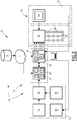
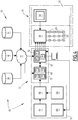
- the figures 1 and 2 schematically illustrate a first installation 10 provided with a light intensity control system 12 according to the invention.
- the installation 10 is for example an installation located in a body of water 11, such as an ocean, a sea, a lake or a river.
- the installation 10 is for example floating. It is advantageously formed by a surface naval support which may for example be a floating production, storage and unloading unit called FPSO (“Floating Production, Storage and Offloading”), a floating unit dedicated to liquefied natural gas called FLNG (“Floating Liquified Natural Gas”), a semi-submersible platform, which can be for example a TLP (“Tension Leg Platform”), an unloading buoy, a floating vertical column or a ship .
- FPSO floating Production, Storage and Offloading
- FLNG Floating Liquified Natural Gas
- TLP Tunnel Leg Platform
- unloading buoy a floating vertical column or a ship .
- the installation 10 is a fixed rigid structure of the “jacket” type or an oscillating structure secured to the seabed.
- the installation 10 is an installation located on land.
- the installation 10 comprises a structure 14 and advantageously at least one unit 16 for prospecting, producing, or / and recovering fluid, in particular hydrocarbons.
- the installation 10 further comprises a lighting assembly 18 and the light intensity control system 12, suitable for controlling the lighting assembly 18.
- the installation 10 is located in an environment comprising air masses 20 in circulation.
- the environment of the installation 10 further comprises volatiles 22, in particular groups 24 of birds 22 flying around the installation 10.
- the birds 22 are, for example, migratory birds.
- the lighting assembly 18 here comprises a plurality of light sources 26.
- the light sources 26 are for example electrical sources, such as lamps and / or projectors.
- the light sources 26 include thermal sources, such as torches.
- the lighting assembly 18 comprises a plurality of lighting lines 28 each comprising at least one light source 26, and a power distribution board 30 (“Power Distribution Board” or “PDB”) connected to each line of lighting 28.
- a power distribution board 30 (“Power Distribution Board” or “PDB”) connected to each line of lighting 28.
- the lighting assembly 18 further comprises an emergency unit 32, suitable for guaranteeing emergency lighting.
- each lighting line 28 is connected to the distribution board 30 to be selectively controlled in light intensity by the distribution board 30.
- the lines 28 are shown here with light sources 26 in series, although branches, and parallel sources 26 may also be provided on each line 28.
- the power distribution board 30 is able to selectively adjust the light intensity of each light source 26 between a maximum value and a minimum value required to guarantee the safety of the operators present in the installation 10.
- the power distribution board 30 is controlled by the control system 12.
- the back-up unit 32 is able to directly control the distribution panel 30. It comprises for example an integrated control and safety system 34 (“Integrated Control and Safety System” or “ICSS” in English ).
- Integrated Control and Safety System or “ICSS” in English ).
- the control system 12 comprises a unit 40 for collecting meteorological data in a region 42 located around the installation 10, an interface 44 for interrogating a database 46 of the presence of birds 22 in the region 42 around of the installation 10, and a prediction unit 48 connected to the collection unit 40 and to the interrogation interface 44 to calculate a probability of passage of a flow of birds 22 opposite the installation 10 in a function of time.
- the control system 12 further comprises a control unit 50 of the light sources 26 as a function of the calculated probability of passage, connected to the lighting assembly 18.
- the collection unit 40 is formed by a weather station 52.
- the weather station 52 comprises sensors 54, at least one master clock 56, and a weather monitoring system 58 connected to the sensors 54 and to the clock 56.
- the collection unit 40 comprises a system 60 for remote supervision.
- the sensors 54 are, for example, sensors for measuring the speed and direction of the wind, sensors for measuring temperature or / and sensors for measuring atmospheric pressure.
- the sensors 54 are located locally on the installation 10 or in the vicinity thereof in the region 42.
- the clock 56 is suitable for allowing a dating of the measurements taken by the sensors 54. It is connected to the meteorological monitoring system 58.
- the meteorological monitoring system 58 is able to collect the meteorological parameters measured locally by the sensors 54 and the time data received from the clock 56.
- the system 58 comprises at least one computer provided with a processor and a memory. containing software applications specific to be executed by the processor.
- the memory contains at least one application for collecting data from the sensors 54 and from the clock 56.
- the collection application is suitable for recovering the analog and digital data from the sensors 54 and for displaying them or / and integrating them into a database. of temporal data.
- the remote supervision system 60 is able to display the malfunction information of the systems of the weather station 52.
- the bird presence database 46 contains information on the type, position, and / or altitude of birds 22 moving to region 42 around facility 10.
- the database 46 is for example a database accessible via the Internet, in particular. Movebank for Animal Tracking Data (https://www.movebank.org/) - data in this database can be accessed upon request and authorization.
- the database 46 is generally remote from the installation 10. It can be interrogated remotely by means of the interface 44.
- the interface 44 is for example a data transmission network, such as the Internet network, operating in particular according to the TCP / IP protocol.
- the prediction unit 48 is suitable for interrogating the collection unit 40 and the database 46 for the presence of volatiles through the interface 44 in order to calculate a probability of passage of a flow of volatiles 22 opposite the installation 10 as a function of time, on the basis of the meteorological data provided by the collection unit 40, and of the presence data of birds 22 in the region 42 around the installation 10, obtained in the database 46.
- the prediction unit 48 comprises a computer comprising at least one processor 70 and a memory 72 containing software applications suitable for being executed by the processor 70.
- the memory 72 preferably contains an application 74 for determining predictive meteorological data from the measurements collected by the weather station 52, an application 76 for recovering data on the movement of birds 22, from the database 46, through the interface 44, and an application 78 for calculating a probability of passage of birds 22 opposite the installation 10 as a function of time.
- the determination application 74 is able to establish a meteorological prediction as a function of time in the region 42 located around the installation 10, on the basis of a meteorological model and the local meteorological parameters measured by the sensors 54 of the station. weather 52.
- Predictive meteorological data are, for example, wind speed and direction, atmospheric pressure, temperature, precipitation at a plurality of points in region 42, at different latitudes, longitudes and altitudes.
- the determination application 74 is suitable for determining, over time, the speed and direction of the flow of air masses 20 around the installation 10, at different altitudes, capable of accommodating birds 22. in flight.
- the calculation application 78 is thus able to use the predictive meteorological data, in particular the wind speeds and the flows of the air masses at various points around the installation 10, over time, to predict a movement of the air masses.
- groups 24 of birds 22 as a function of time from the known positions of the groups 24 of birds 22 extracted from the database 46, and from a mathematical model of movement.
- This calculation makes it possible to obtain a probability of passage of birds 22 facing the installation 10 as a function of time, in a time interval for example between one hour and a few days (from a few hours to 3 days for the figure 2 , from a few hours to 10 days for the figure 3 and 4 ).
- This probability is for example calculated at a frequency between one hour and one day.
- the control unit 50 is for example an industrial programmable logic controller (“Progammable Logic Controller” or “PLC”).
- PLC Programmable Logic Controller
- the control unit 50 is connected to the prediction unit 48 and to the lighting assembly 18. It is able to control the lighting assembly 18 to adjust the intensity of the light sources 26 as a function of the light source. probability of passage calculated by the prediction unit 48.
- the control unit 50 comprises for example a computer provided with at least one processor 80 and a memory 82 containing applications suitable for being executed by the processor.
- the memory 82 contains in particular an application 84 for recovering the passage probabilities calculated as a function of time by the prediction unit 48, and an application 86 for generating a command for the lighting assembly 18, in particular the distribution board 30, according to the calculated probabilities of passage.
- the generation application 86 is suitable for generating a command for the distribution board 30 to reduce the light intensity of the light sources 26 by at least one line 28 when the calculated probability of passage increases over time, for example example goes above a predetermined threshold, or a predetermined gradient.
- the reduction in light intensity is for example carried out gradually over time, the reduction being maximum when the probability of passage is maximum.
- control unit 50 In operation, regardless of the calculated probability of passage, the control unit 50 is able to maintain a minimum light intensity of the or each light source 26 of the installation 10 to guarantee the safety of the operators of the installation 10. when installation 10 is active.
- the emergency unit 32 is able to directly control the control unit 50, to guarantee emergency lighting, independently of the probability of passage calculated by the prediction unit 48.
- Emergency lighting consists, for example, of illuminating at least one light source 26 at an emergency intensity greater than the minimum light intensity defined above, even if the probability of passage calculated by the prediction unit 48 makes it necessary to maintain l minimum light intensity.
- the sensors 54 of the weather station 52 read local weather parameters in the vicinity of the installation 10 and the clock 56 reads temporal data which feeds the data collection applications of the weather monitoring system 58.
- the database 46 is fed with positioning data of birds 22 in the region 42.
- the application 74 for determining predictive meteorological data, and the application 76 for recovering positioning data of birds 22 are then activated by the prediction unit 48.
- the determination application 74 then establishes predictive meteorological data, such as wind speed and direction, atmospheric pressure, temperature, precipitation at a plurality of points in the region 42. over time, in a time interval as defined above.
- the applications 74, 76 feed the calculation application 78 of the prediction unit 48 which calculates a probability of passage of passage of birds 22 opposite the installation 10 as a function of time in the aforementioned time interval, and at the chosen frequency as defined above.
- the probability of passage as a function of time calculated by the prediction unit 48 is recovered by the recovery application 84 of the control unit 50.
- the generation application 86 generates a command. of the distribution board 30.
- the control provides for a decrease in the light intensity of each source 26.
- This decrease is for example progressive over time. It is limited to maintain a minimum light intensity in the installation 10 required for the safety of each operator of the installation 10.
- the light intensity of the installation 10 is adapted over time as a function of the presence of volatiles 22 in the vicinity of the installation 10.
- the light intensity is greatly reduced when this probability increases significantly, this being the case. which reduces the risk of disturbance to wildlife flying around the facility 10.
- This attenuation of the impact of the installation 10 on the birds 22 depends on the type of bird 22. It is also very effective.
- the prediction unit 48 also includes an interface for querying a database 90 containing online predictive meteorological data.
- This interface is for example the interface 44.
- the database 90 is for example a short-term weather forecasting system such as the PEARP system of Mluso France or the EPS and / or CEP systems.
- the method then comprises an interrogation of the database 90 by the interface 44 to obtain additional predictive meteorological data in addition to the predictive meteorological data obtained by the application 74 via the meteorological station 52.
- the most precise predictive meteorological data are then used by the prediction unit 48, to calculate the probability of passage as a function of time, as described above.
- control unit 50 is able to query a maintenance database 94 on the installation 10, for example through the interface 44, to obtain the dates and / or potential hours of maintenance planned on the installation 10.
- the generation application 86 is able to signal a conflict with the date and / or l potential time of maintenance, or even to modify the date and / or the potential time of maintenance in the database 94.
- the installation 10 is for example a factory operating continuously or a large urban installation. It comprises a structure 14, a lighting assembly 18 of the installation 10, and a system 12 for controlling the light intensity generated by the installation 10, as described above.
Landscapes
- Life Sciences & Earth Sciences (AREA)
- Environmental Sciences (AREA)
- Birds (AREA)
- Animal Husbandry (AREA)
- Biodiversity & Conservation Biology (AREA)
- Physics & Mathematics (AREA)
- Engineering & Computer Science (AREA)
- Insects & Arthropods (AREA)
- Pest Control & Pesticides (AREA)
- Wood Science & Technology (AREA)
- Zoology (AREA)
- Optics & Photonics (AREA)
- Circuit Arrangement For Electric Light Sources In General (AREA)
- Exposure Of Semiconductors, Excluding Electron Or Ion Beam Exposure (AREA)
Claims (15)
- Verfahren zum Steuern der Lichtintensität einer Anlage (10), umfassend den folgenden Schritt:- Steuern, durch eine Steuereinheit (50), von mindestens einer Lichtquelle (26) der Anlage (10), wobei das Verfahren durch die folgenden Schritte gekennzeichnet ist:- Bestimmen von prädiktiven meteorologischen Daten in einem Gebiet (42), das sich um die Anlage (10) befindet;- Abfragen einer Datenbank (46) über das Vorhandensein von Vögeln (22) in dem Gebiet (42) um die Anlage (10);- Berechnen, durch eine Prädiktionseinheit (48), einer Wahrscheinlichkeit eines Vorbeifliegens von Vögeln (22) in Bezug auf die Anlage (10) abhängig von der Zeit basierend auf den prädiktiven meteorologischen Daten und von Daten über das Vorhandensein von Vögeln (22) in dem Gebiet (42) um die Anlage (10);das Steuern, durch eine Steuereinheit (50), von mindestens einer Lichtquelle (26) der Anlage (10), was sich auf die Vorbeifliegenwahrscheinlichkeit stützt, die von der Prädiktionseinheit (48) berechnet wird.
- Verfahren nach Anspruch 1, wobei das Steuern mindestens einer Lichtquelle (26) der Anlage (10) das Verringern der Lichtintensität der oder jeder Lichtquelle (26) der Anlage (10) umfasst, wenn die Vorbeifliegenwahrscheinlichkeit, die von der Prädiktionseinheit (48) berechnet wird, steigt.
- Verfahren nach Anspruch 2, wobei das Steuern mindestens einer Lichtquelle (26) der Anlage (10) das Beibehalten einer Lichtintensität der oder jeder Lichtquelle (26) der Anlage (10) unabhängig von der Vorbeifliegenwahrscheinlichkeit, die von der Prädiktionseinheit (48) berechnet wird, umfasst.
- Verfahren nach einem der Ansprüche 2 oder 3, wobei das Steuern mindestens einer Lichtquelle (26) der Anlage (10) im Notfall die Aktivierung mindestens einer Lichtquelle (26) der Anlage (10) mit einer Notfallintensität durch eine Notfalleinheit (32) unabhängig von der von der Prädiktionseinheit (48) berechneten Vorbeifliegenwahrscheinlichkeit umfasst.
- Verfahren nach einem der vorherigen Ansprüche, wobei das Bestimmen von prädiktiven meteorologischen Daten das Messen von lokalen meteorologischen Parametern auf Ebene der Anlage (10) durch eine Wetterstation (52) und das Erstellen der prädiktiven meteorologischen Daten in dem Gebiet (42) durch eine Bestimmungsanwendung (74) anhand der lokalen meteorologischen Parameter, die an der Anlage (10) gemessen werden, umfasst.
- Verfahren nach einem der vorherigen Ansprüche, wobei das Bestimmen von prädiktiven meteorologischen Daten das Abfragen einer Datenbank (90) umfasst, die prädiktive meteorologische Online-Daten enthält.
- Verfahren nach Anspruch 5 und 6 zusammengenommen, wobei das Bestimmen der prädiktiven meteorologischen Daten ein Vergleich zwischen den prädiktiven meteorologischen Daten, die anhand der gemessenen lokalen meteorologischen Daten erlangt werden, und den prädiktiven meteorologischen Daten, die aus der Datenbank (90) erlangt werden, die prädiktive meteorologische Online-Daten enthält, umfasst.
- Verfahren nach einem der vorherigen Ansprüche, umfassend das Abfragen einer Wartungsdatenbank (46) der Anlage (10), um mindestens ein potenzielles Datum und/oder eine potenzielle Uhrzeit einer geplanten Wartung an der Anlage (10) zu bestimmen, und das Abrufen der von der Prädiktionseinheit (48) berechneten Vorbeifliegenwahrscheinlichkeit zu dem potenziellen Wartungsdatum und/oder der potenziellen Uhrzeit.
- System (12) zum Steuern der Lichtintensität einer Anlage (10), umfassend- eine Steuereinheit (50) mindestens einer Lichtquelle (26) der Anlage (10), wobei das System durch Folgendes gekennzeichnet:- eine Datenbank (46) über das Vorhandensein von Vögeln (22) in dem Gebiet (42) um die Anlage (10);- eine Prädiktionseinheit (48), die angepasst ist, um prädiktive meteorologische Daten in einem Gebiet (42) um die Anlage (10) zu bestimmen, wobei die Prädiktionseinheit (48) angepasst ist, um die Datenbank (46) des Vorhandenseins von Vögeln (22) abzufragen, um eine Vorbeifliegenwahrscheinlichkeit von Vögeln (22) in Bezug auf die Anlage (10) abhängig von der Zeit, basierend auf den prädiktiven meteorologischen Daten und den Daten des Vorhandenseins von Vögeln (22) in dem Gebiet (42) um die Anlage (10) zu berechnen;das Steuern, durch die Steuereinheit (50), von mindestens einer Lichtquelle (26) der Anlage (10), was sich auf die Vorbeifliegenwahrscheinlichkeit stützt, die von der Prädiktionseinheit (48) berechnet wird.
- System (12) nach Anspruch 9, wobei die Steuereinheit (50) von mindestens einer Lichtquelle (26) der Anlage (10) geeignet ist, um die Lichtintensität der oder jeder Lichtquelle (26) der Anlage (10) zu verringern, wenn die Vorbeifliegenwahrscheinlichkeit, die von der Prädiktionseinheit (48) berechnet wird, steigt.
- System (12) nach Anspruch 10, wobei die Steuereinheit (50) von mindestens einer Lichtquelle (26) der Anlage (10) geeignet ist, um eine minimale Lichtintensität der oder jeder Lichtquelle (26) der Anlage (10) unabhängig von der Vorbeifliegenwahrscheinlichkeit, die von der Prädiktionseinheit (48) berechnet wird, beizubehalten.
- System (12) nach einem der Ansprüche 10 oder 11, umfassend eine Sicherheitseinheit (34), die geeignet ist, um mindestens eine Lichtquelle (26) der Anlage (10) unabhängig von der Vorbeifliegenwahrscheinlichkeit, die von der Prädiktionseinheit (48) berechnet wird, zu aktivieren.
- System (12) nach einem der Ansprüche 9 bis 12, umfassend eine Sammeleinheit (40) meteorologischer Daten, umfassend eine Wetterstation (52), die geeignet ist, um lokale meteorologische Daten auf Ebene der Anlage (10) zu messen, und wobei ein meteorologisches Verfolgungssystem (58) und die Prädiktionseinheit (48) geeignet sind, um anhand der gemessenen lokalen meteorologischen Parametern prädiktive meteorologische Daten in dem Gebiet (42) um die Anlage (10) zu bestimmen.
- System (12) nach einem der Ansprüche 9 bis 13, wobei die Prädiktionseinheit (48) geeignet ist, um eine Datenbank (90) abzufragen, die prädiktive meteorologische Online-Daten enthält.
- System (12) nach einem der Ansprüche 9 bis 14, wobei die Steuereinheit (50) geeignet ist, um eine Wartungsdatenbank (94) der Anlage (10) abzufragen, um mindestens ein potenzielles Datum und/oder eine potenzielle Uhrzeit einer geplanten Wartung an der Anlage (10) zu bestimmen, wobei die Steuereinheit (50) geeignet ist, um die von der Prädiktionseinheit (48) berechnete Vorbeifliegenwahrscheinlichkeit zu dem potenziellen Wartungsdatum und/oder der potenziellen Uhrzeit abzurufen.
Applications Claiming Priority (2)
| Application Number | Priority Date | Filing Date | Title |
|---|---|---|---|
| FR1758572A FR3071330B1 (fr) | 2017-09-15 | 2017-09-15 | Procede de commande de l'intensite lumineuse d'une installation, et systeme associe |
| PCT/EP2018/074797 WO2019053154A1 (fr) | 2017-09-15 | 2018-09-13 | Procédé de commande de l'intensité lumineuse d'une installation, et système associé |
Publications (2)
| Publication Number | Publication Date |
|---|---|
| EP3681280A1 EP3681280A1 (de) | 2020-07-22 |
| EP3681280B1 true EP3681280B1 (de) | 2022-01-05 |
Family
ID=61027831
Family Applications (1)
| Application Number | Title | Priority Date | Filing Date |
|---|---|---|---|
| EP18765479.3A Active EP3681280B1 (de) | 2017-09-15 | 2018-09-13 | Verfahren zur steuerung der lichtintensität einer anlage und zugehöriges system |
Country Status (5)
| Country | Link |
|---|---|
| US (1) | US10887969B2 (de) |
| EP (1) | EP3681280B1 (de) |
| FR (1) | FR3071330B1 (de) |
| IL (1) | IL273166B2 (de) |
| WO (1) | WO2019053154A1 (de) |
Families Citing this family (2)
| Publication number | Priority date | Publication date | Assignee | Title |
|---|---|---|---|---|
| CN110546900B (zh) | 2017-06-04 | 2021-03-12 | Lg 电子株式会社 | 用于在无线通信系统中接收系统信息的方法及其装置 |
| US12019598B2 (en) * | 2020-01-24 | 2024-06-25 | International Business Machines Corporation | Reducing database maintenance effort |
Family Cites Families (3)
| Publication number | Priority date | Publication date | Assignee | Title |
|---|---|---|---|---|
| US5450063A (en) * | 1993-10-18 | 1995-09-12 | Peregrine, Inc. | Bird avert system |
| JP5357771B2 (ja) * | 2006-12-18 | 2013-12-04 | コーニンクレッカ フィリップス エヌ ヴェ | 照明システムを動作するための光源及び方法 |
| US10231304B2 (en) * | 2013-02-20 | 2019-03-12 | Current USA, Inc. | Habitat control system |
-
2017
- 2017-09-15 FR FR1758572A patent/FR3071330B1/fr not_active Expired - Fee Related
-
2018
- 2018-09-13 EP EP18765479.3A patent/EP3681280B1/de active Active
- 2018-09-13 WO PCT/EP2018/074797 patent/WO2019053154A1/fr not_active Ceased
- 2018-09-13 IL IL273166A patent/IL273166B2/en unknown
- 2018-09-13 US US16/646,214 patent/US10887969B2/en active Active
Also Published As
| Publication number | Publication date |
|---|---|
| WO2019053154A1 (fr) | 2019-03-21 |
| IL273166B1 (en) | 2023-08-01 |
| IL273166A (en) | 2020-04-30 |
| FR3071330A1 (fr) | 2019-03-22 |
| IL273166B2 (en) | 2023-12-01 |
| FR3071330B1 (fr) | 2019-09-06 |
| EP3681280A1 (de) | 2020-07-22 |
| US20200275543A1 (en) | 2020-08-27 |
| US10887969B2 (en) | 2021-01-05 |
Similar Documents
| Publication | Publication Date | Title |
|---|---|---|
| Kuhlbrodt et al. | A glimpse into the future: the 2023 ocean temperature and sea ice extremes in the context of longer-term climate change | |
| Marsh et al. | Climate change from 1850 to 2005 simulated in CESM1 (WACCM) | |
| Murphy et al. | Temporal variation in Antarctic sea-ice: analysis of a long term fast-ice record from the South Orkney Islands | |
| Sakamoto et al. | Moisture sources and life cycle of convective systems over western Colombia | |
| Rahn et al. | A synoptic climatology of the near-surface wind along the west coast of South America. | |
| Dickerson‐Lange et al. | Ranking forest effects on snow storage: A decision tool for forest management | |
| Lestari et al. | ENSO influences on rainfall extremes around Sulawesi and Maluku Islands in the eastern Indonesian maritime continent | |
| Patrick et al. | Operational thermal remote sensing and lava flow monitoring at the Hawaiian Volcano Observatory | |
| Zhang et al. | Sunlight-absorbing aerosol amplifies the seasonal cycle in low-cloud fraction over the southeast Atlantic | |
| FR3071330B1 (fr) | Procede de commande de l'intensite lumineuse d'une installation, et systeme associe | |
| McGimsey et al. | 2009 Volcanic activity in Alaska, Kamchatka, and the Kurile Islands: Summary of events and response of the Alaska Volcano Observatory | |
| Chin et al. | Multi-decadal variations of atmospheric aerosols from 1980 to 2009: sources and regional trends. | |
| Heidinger et al. | Global daytime distribution of overlapping cirrus cloud from NOAA’s Advanced Very High Resolution Radiometer | |
| Rutllant et al. | A comparison of spring coastal upwelling off central Chile at the extremes of the 1996–1997 ENSO cycle | |
| Feidas et al. | Monitoring mesoscale convective cloud systems associated with heavy storms using Meteosat imagery | |
| Akilan et al. | Perturbations in atmospheric gaseous components over coastal Antarctica detected in GPS signals and its natural origin to volcanic eruption | |
| Yuan et al. | Anthropogenic decline of African dust: Insights from the Holocene records and beyond | |
| Melani et al. | A four year (2007–2010) analysis of long-lasting deep convective systems in the Mediterranean basin | |
| Gimeno et al. | Ocean evaporation and precipitation | |
| FR3120266A1 (fr) | Système électronique d’aide au pilotage d’un drone, procédé et programme d’ordinateur associés | |
| Capuli | Friday the 13th Hailstorm in the Province of Bulacan, Philippines (13 August 2021): A Case Study: GH Capuli | |
| Goddard et al. | The impacts of Stratospheric Aerosol Injection on Antarctic ice loss depend on injection location | |
| Yurganov | The relationship between methane transport to the atmosphere and the decay of the Kara Sea ice cover: satellite data for 2003-2019 | |
| Butterworth et al. | Annual carbon dioxide flux over seasonal sea ice in the Canadian Arctic | |
| Hvidegaard et al. | ESA CryoVEx 2014-Airborne ASIRAS radar and laser scanner measurements during 2014 CryoVEx campaign in the Arctic |
Legal Events
| Date | Code | Title | Description |
|---|---|---|---|
| STAA | Information on the status of an ep patent application or granted ep patent |
Free format text: STATUS: UNKNOWN |
|
| STAA | Information on the status of an ep patent application or granted ep patent |
Free format text: STATUS: THE INTERNATIONAL PUBLICATION HAS BEEN MADE |
|
| PUAI | Public reference made under article 153(3) epc to a published international application that has entered the european phase |
Free format text: ORIGINAL CODE: 0009012 |
|
| STAA | Information on the status of an ep patent application or granted ep patent |
Free format text: STATUS: REQUEST FOR EXAMINATION WAS MADE |
|
| 17P | Request for examination filed |
Effective date: 20200313 |
|
| AK | Designated contracting states |
Kind code of ref document: A1 Designated state(s): AL AT BE BG CH CY CZ DE DK EE ES FI FR GB GR HR HU IE IS IT LI LT LU LV MC MK MT NL NO PL PT RO RS SE SI SK SM TR |
|
| AX | Request for extension of the european patent |
Extension state: BA ME |
|
| DAV | Request for validation of the european patent (deleted) | ||
| DAX | Request for extension of the european patent (deleted) | ||
| REG | Reference to a national code |
Ref country code: DE Ref legal event code: R079 Ref document number: 602018029168 Country of ref document: DE Free format text: PREVIOUS MAIN CLASS: A01M0029100000 Ipc: H05B0047115000 |
|
| GRAP | Despatch of communication of intention to grant a patent |
Free format text: ORIGINAL CODE: EPIDOSNIGR1 |
|
| STAA | Information on the status of an ep patent application or granted ep patent |
Free format text: STATUS: GRANT OF PATENT IS INTENDED |
|
| RIC1 | Information provided on ipc code assigned before grant |
Ipc: H05B 47/115 20200101AFI20210311BHEP Ipc: A01M 29/10 20110101ALI20210311BHEP |
|
| INTG | Intention to grant announced |
Effective date: 20210329 |
|
| GRAJ | Information related to disapproval of communication of intention to grant by the applicant or resumption of examination proceedings by the epo deleted |
Free format text: ORIGINAL CODE: EPIDOSDIGR1 |
|
| STAA | Information on the status of an ep patent application or granted ep patent |
Free format text: STATUS: REQUEST FOR EXAMINATION WAS MADE |
|
| GRAP | Despatch of communication of intention to grant a patent |
Free format text: ORIGINAL CODE: EPIDOSNIGR1 |
|
| STAA | Information on the status of an ep patent application or granted ep patent |
Free format text: STATUS: GRANT OF PATENT IS INTENDED |
|
| INTC | Intention to grant announced (deleted) | ||
| INTG | Intention to grant announced |
Effective date: 20210803 |
|
| GRAS | Grant fee paid |
Free format text: ORIGINAL CODE: EPIDOSNIGR3 |
|
| GRAA | (expected) grant |
Free format text: ORIGINAL CODE: 0009210 |
|
| STAA | Information on the status of an ep patent application or granted ep patent |
Free format text: STATUS: THE PATENT HAS BEEN GRANTED |
|
| AK | Designated contracting states |
Kind code of ref document: B1 Designated state(s): AL AT BE BG CH CY CZ DE DK EE ES FI FR GB GR HR HU IE IS IT LI LT LU LV MC MK MT NL NO PL PT RO RS SE SI SK SM TR |
|
| REG | Reference to a national code |
Ref country code: GB Ref legal event code: FG4D Free format text: NOT ENGLISH |
|
| REG | Reference to a national code |
Ref country code: CH Ref legal event code: EP |
|
| REG | Reference to a national code |
Ref country code: AT Ref legal event code: REF Ref document number: 1461757 Country of ref document: AT Kind code of ref document: T Effective date: 20220115 |
|
| REG | Reference to a national code |
Ref country code: DE Ref legal event code: R096 Ref document number: 602018029168 Country of ref document: DE |
|
| REG | Reference to a national code |
Ref country code: IE Ref legal event code: FG4D Free format text: LANGUAGE OF EP DOCUMENT: FRENCH |
|
| REG | Reference to a national code |
Ref country code: NO Ref legal event code: T2 Effective date: 20220105 |
|
| REG | Reference to a national code |
Ref country code: LT Ref legal event code: MG9D |
|
| REG | Reference to a national code |
Ref country code: NL Ref legal event code: MP Effective date: 20220105 |
|
| REG | Reference to a national code |
Ref country code: AT Ref legal event code: MK05 Ref document number: 1461757 Country of ref document: AT Kind code of ref document: T Effective date: 20220105 |
|
| PG25 | Lapsed in a contracting state [announced via postgrant information from national office to epo] |
Ref country code: NL Free format text: LAPSE BECAUSE OF FAILURE TO SUBMIT A TRANSLATION OF THE DESCRIPTION OR TO PAY THE FEE WITHIN THE PRESCRIBED TIME-LIMIT Effective date: 20220105 |
|
| PG25 | Lapsed in a contracting state [announced via postgrant information from national office to epo] |
Ref country code: SE Free format text: LAPSE BECAUSE OF FAILURE TO SUBMIT A TRANSLATION OF THE DESCRIPTION OR TO PAY THE FEE WITHIN THE PRESCRIBED TIME-LIMIT Effective date: 20220105 Ref country code: RS Free format text: LAPSE BECAUSE OF FAILURE TO SUBMIT A TRANSLATION OF THE DESCRIPTION OR TO PAY THE FEE WITHIN THE PRESCRIBED TIME-LIMIT Effective date: 20220105 Ref country code: PT Free format text: LAPSE BECAUSE OF FAILURE TO SUBMIT A TRANSLATION OF THE DESCRIPTION OR TO PAY THE FEE WITHIN THE PRESCRIBED TIME-LIMIT Effective date: 20220505 Ref country code: LT Free format text: LAPSE BECAUSE OF FAILURE TO SUBMIT A TRANSLATION OF THE DESCRIPTION OR TO PAY THE FEE WITHIN THE PRESCRIBED TIME-LIMIT Effective date: 20220105 Ref country code: HR Free format text: LAPSE BECAUSE OF FAILURE TO SUBMIT A TRANSLATION OF THE DESCRIPTION OR TO PAY THE FEE WITHIN THE PRESCRIBED TIME-LIMIT Effective date: 20220105 Ref country code: ES Free format text: LAPSE BECAUSE OF FAILURE TO SUBMIT A TRANSLATION OF THE DESCRIPTION OR TO PAY THE FEE WITHIN THE PRESCRIBED TIME-LIMIT Effective date: 20220105 Ref country code: BG Free format text: LAPSE BECAUSE OF FAILURE TO SUBMIT A TRANSLATION OF THE DESCRIPTION OR TO PAY THE FEE WITHIN THE PRESCRIBED TIME-LIMIT Effective date: 20220405 |
|
| PG25 | Lapsed in a contracting state [announced via postgrant information from national office to epo] |
Ref country code: PL Free format text: LAPSE BECAUSE OF FAILURE TO SUBMIT A TRANSLATION OF THE DESCRIPTION OR TO PAY THE FEE WITHIN THE PRESCRIBED TIME-LIMIT Effective date: 20220105 Ref country code: LV Free format text: LAPSE BECAUSE OF FAILURE TO SUBMIT A TRANSLATION OF THE DESCRIPTION OR TO PAY THE FEE WITHIN THE PRESCRIBED TIME-LIMIT Effective date: 20220105 Ref country code: GR Free format text: LAPSE BECAUSE OF FAILURE TO SUBMIT A TRANSLATION OF THE DESCRIPTION OR TO PAY THE FEE WITHIN THE PRESCRIBED TIME-LIMIT Effective date: 20220406 Ref country code: FI Free format text: LAPSE BECAUSE OF FAILURE TO SUBMIT A TRANSLATION OF THE DESCRIPTION OR TO PAY THE FEE WITHIN THE PRESCRIBED TIME-LIMIT Effective date: 20220105 Ref country code: AT Free format text: LAPSE BECAUSE OF FAILURE TO SUBMIT A TRANSLATION OF THE DESCRIPTION OR TO PAY THE FEE WITHIN THE PRESCRIBED TIME-LIMIT Effective date: 20220105 |
|
| PG25 | Lapsed in a contracting state [announced via postgrant information from national office to epo] |
Ref country code: IS Free format text: LAPSE BECAUSE OF FAILURE TO SUBMIT A TRANSLATION OF THE DESCRIPTION OR TO PAY THE FEE WITHIN THE PRESCRIBED TIME-LIMIT Effective date: 20220505 |
|
| REG | Reference to a national code |
Ref country code: DE Ref legal event code: R097 Ref document number: 602018029168 Country of ref document: DE |
|
| PG25 | Lapsed in a contracting state [announced via postgrant information from national office to epo] |
Ref country code: SM Free format text: LAPSE BECAUSE OF FAILURE TO SUBMIT A TRANSLATION OF THE DESCRIPTION OR TO PAY THE FEE WITHIN THE PRESCRIBED TIME-LIMIT Effective date: 20220105 Ref country code: SK Free format text: LAPSE BECAUSE OF FAILURE TO SUBMIT A TRANSLATION OF THE DESCRIPTION OR TO PAY THE FEE WITHIN THE PRESCRIBED TIME-LIMIT Effective date: 20220105 Ref country code: RO Free format text: LAPSE BECAUSE OF FAILURE TO SUBMIT A TRANSLATION OF THE DESCRIPTION OR TO PAY THE FEE WITHIN THE PRESCRIBED TIME-LIMIT Effective date: 20220105 Ref country code: EE Free format text: LAPSE BECAUSE OF FAILURE TO SUBMIT A TRANSLATION OF THE DESCRIPTION OR TO PAY THE FEE WITHIN THE PRESCRIBED TIME-LIMIT Effective date: 20220105 Ref country code: DK Free format text: LAPSE BECAUSE OF FAILURE TO SUBMIT A TRANSLATION OF THE DESCRIPTION OR TO PAY THE FEE WITHIN THE PRESCRIBED TIME-LIMIT Effective date: 20220105 Ref country code: CZ Free format text: LAPSE BECAUSE OF FAILURE TO SUBMIT A TRANSLATION OF THE DESCRIPTION OR TO PAY THE FEE WITHIN THE PRESCRIBED TIME-LIMIT Effective date: 20220105 |
|
| PLBE | No opposition filed within time limit |
Free format text: ORIGINAL CODE: 0009261 |
|
| STAA | Information on the status of an ep patent application or granted ep patent |
Free format text: STATUS: NO OPPOSITION FILED WITHIN TIME LIMIT |
|
| PG25 | Lapsed in a contracting state [announced via postgrant information from national office to epo] |
Ref country code: AL Free format text: LAPSE BECAUSE OF FAILURE TO SUBMIT A TRANSLATION OF THE DESCRIPTION OR TO PAY THE FEE WITHIN THE PRESCRIBED TIME-LIMIT Effective date: 20220105 |
|
| 26N | No opposition filed |
Effective date: 20221006 |
|
| PG25 | Lapsed in a contracting state [announced via postgrant information from national office to epo] |
Ref country code: SI Free format text: LAPSE BECAUSE OF FAILURE TO SUBMIT A TRANSLATION OF THE DESCRIPTION OR TO PAY THE FEE WITHIN THE PRESCRIBED TIME-LIMIT Effective date: 20220105 |
|
| REG | Reference to a national code |
Ref country code: DE Ref legal event code: R119 Ref document number: 602018029168 Country of ref document: DE |
|
| PG25 | Lapsed in a contracting state [announced via postgrant information from national office to epo] |
Ref country code: MC Free format text: LAPSE BECAUSE OF FAILURE TO SUBMIT A TRANSLATION OF THE DESCRIPTION OR TO PAY THE FEE WITHIN THE PRESCRIBED TIME-LIMIT Effective date: 20220105 |
|
| REG | Reference to a national code |
Ref country code: CH Ref legal event code: PL |
|
| REG | Reference to a national code |
Ref country code: BE Ref legal event code: MM Effective date: 20220930 |
|
| PG25 | Lapsed in a contracting state [announced via postgrant information from national office to epo] |
Ref country code: LU Free format text: LAPSE BECAUSE OF NON-PAYMENT OF DUE FEES Effective date: 20220913 |
|
| P01 | Opt-out of the competence of the unified patent court (upc) registered |
Effective date: 20230601 |
|
| PG25 | Lapsed in a contracting state [announced via postgrant information from national office to epo] |
Ref country code: LI Free format text: LAPSE BECAUSE OF NON-PAYMENT OF DUE FEES Effective date: 20220930 Ref country code: IT Free format text: LAPSE BECAUSE OF FAILURE TO SUBMIT A TRANSLATION OF THE DESCRIPTION OR TO PAY THE FEE WITHIN THE PRESCRIBED TIME-LIMIT Effective date: 20220105 Ref country code: IE Free format text: LAPSE BECAUSE OF NON-PAYMENT OF DUE FEES Effective date: 20220913 Ref country code: DE Free format text: LAPSE BECAUSE OF NON-PAYMENT OF DUE FEES Effective date: 20230401 Ref country code: CH Free format text: LAPSE BECAUSE OF NON-PAYMENT OF DUE FEES Effective date: 20220930 |
|
| PG25 | Lapsed in a contracting state [announced via postgrant information from national office to epo] |
Ref country code: BE Free format text: LAPSE BECAUSE OF NON-PAYMENT OF DUE FEES Effective date: 20220930 |
|
| PG25 | Lapsed in a contracting state [announced via postgrant information from national office to epo] |
Ref country code: CY Free format text: LAPSE BECAUSE OF FAILURE TO SUBMIT A TRANSLATION OF THE DESCRIPTION OR TO PAY THE FEE WITHIN THE PRESCRIBED TIME-LIMIT Effective date: 20220105 |
|
| PG25 | Lapsed in a contracting state [announced via postgrant information from national office to epo] |
Ref country code: MK Free format text: LAPSE BECAUSE OF FAILURE TO SUBMIT A TRANSLATION OF THE DESCRIPTION OR TO PAY THE FEE WITHIN THE PRESCRIBED TIME-LIMIT Effective date: 20220105 Ref country code: HU Free format text: LAPSE BECAUSE OF FAILURE TO SUBMIT A TRANSLATION OF THE DESCRIPTION OR TO PAY THE FEE WITHIN THE PRESCRIBED TIME-LIMIT; INVALID AB INITIO Effective date: 20180913 |
|
| PG25 | Lapsed in a contracting state [announced via postgrant information from national office to epo] |
Ref country code: TR Free format text: LAPSE BECAUSE OF FAILURE TO SUBMIT A TRANSLATION OF THE DESCRIPTION OR TO PAY THE FEE WITHIN THE PRESCRIBED TIME-LIMIT Effective date: 20220105 |
|
| PG25 | Lapsed in a contracting state [announced via postgrant information from national office to epo] |
Ref country code: MT Free format text: LAPSE BECAUSE OF FAILURE TO SUBMIT A TRANSLATION OF THE DESCRIPTION OR TO PAY THE FEE WITHIN THE PRESCRIBED TIME-LIMIT Effective date: 20220105 |
|
| PGFP | Annual fee paid to national office [announced via postgrant information from national office to epo] |
Ref country code: NO Payment date: 20250909 Year of fee payment: 8 |
|
| PGFP | Annual fee paid to national office [announced via postgrant information from national office to epo] |
Ref country code: GB Payment date: 20250821 Year of fee payment: 8 |
|
| PGFP | Annual fee paid to national office [announced via postgrant information from national office to epo] |
Ref country code: FR Payment date: 20250821 Year of fee payment: 8 |