EP3681025A1 - Hub dynamo - Google Patents
Hub dynamo Download PDFInfo
- Publication number
- EP3681025A1 EP3681025A1 EP18853113.1A EP18853113A EP3681025A1 EP 3681025 A1 EP3681025 A1 EP 3681025A1 EP 18853113 A EP18853113 A EP 18853113A EP 3681025 A1 EP3681025 A1 EP 3681025A1
- Authority
- EP
- European Patent Office
- Prior art keywords
- yoke
- peripheral side
- magnetic pole
- axial direction
- outer peripheral
- Prior art date
- Legal status (The legal status is an assumption and is not a legal conclusion. Google has not performed a legal analysis and makes no representation as to the accuracy of the status listed.)
- Withdrawn
Links
- 230000002093 peripheral effect Effects 0.000 claims description 284
- 238000003825 pressing Methods 0.000 claims description 52
- 238000003475 lamination Methods 0.000 claims description 15
- 229920005989 resin Polymers 0.000 claims description 7
- 239000011347 resin Substances 0.000 claims description 7
- 239000000696 magnetic material Substances 0.000 claims description 6
- 230000002787 reinforcement Effects 0.000 claims description 5
- 230000000149 penetrating effect Effects 0.000 claims description 4
- 230000002159 abnormal effect Effects 0.000 abstract description 15
- 238000010586 diagram Methods 0.000 description 26
- XEEYBQQBJWHFJM-UHFFFAOYSA-N Iron Chemical compound [Fe] XEEYBQQBJWHFJM-UHFFFAOYSA-N 0.000 description 14
- 230000005611 electricity Effects 0.000 description 8
- 229910052742 iron Inorganic materials 0.000 description 7
- 239000000853 adhesive Substances 0.000 description 5
- 230000001070 adhesive effect Effects 0.000 description 5
- 238000003780 insertion Methods 0.000 description 5
- 230000037431 insertion Effects 0.000 description 5
- 238000005304 joining Methods 0.000 description 5
- 230000004907 flux Effects 0.000 description 4
- 238000010030 laminating Methods 0.000 description 3
- 239000000463 material Substances 0.000 description 3
- 229910052751 metal Inorganic materials 0.000 description 3
- 239000002184 metal Substances 0.000 description 3
- 230000003014 reinforcing effect Effects 0.000 description 3
- 229910000976 Electrical steel Inorganic materials 0.000 description 2
- 238000013459 approach Methods 0.000 description 2
- 230000015572 biosynthetic process Effects 0.000 description 2
- 238000004891 communication Methods 0.000 description 2
- 230000008878 coupling Effects 0.000 description 2
- 238000010168 coupling process Methods 0.000 description 2
- 238000005859 coupling reaction Methods 0.000 description 2
- 238000004519 manufacturing process Methods 0.000 description 2
- 238000000034 method Methods 0.000 description 2
- 230000008569 process Effects 0.000 description 2
- 238000012545 processing Methods 0.000 description 2
- 230000009471 action Effects 0.000 description 1
- 229910052782 aluminium Inorganic materials 0.000 description 1
- XAGFODPZIPBFFR-UHFFFAOYSA-N aluminium Chemical compound [Al] XAGFODPZIPBFFR-UHFFFAOYSA-N 0.000 description 1
- 238000005452 bending Methods 0.000 description 1
- 230000000694 effects Effects 0.000 description 1
- 230000007246 mechanism Effects 0.000 description 1
- 239000007769 metal material Substances 0.000 description 1
- 238000012986 modification Methods 0.000 description 1
- 230000004048 modification Effects 0.000 description 1
- 238000004080 punching Methods 0.000 description 1
- 229920003002 synthetic resin Polymers 0.000 description 1
- 239000000057 synthetic resin Substances 0.000 description 1
- 230000005612 types of electricity Effects 0.000 description 1
- 229910000859 α-Fe Inorganic materials 0.000 description 1
Images











Classifications
-
- H—ELECTRICITY
- H02—GENERATION; CONVERSION OR DISTRIBUTION OF ELECTRIC POWER
- H02K—DYNAMO-ELECTRIC MACHINES
- H02K1/00—Details of the magnetic circuit
- H02K1/06—Details of the magnetic circuit characterised by the shape, form or construction
- H02K1/12—Stationary parts of the magnetic circuit
- H02K1/14—Stator cores with salient poles
- H02K1/145—Stator cores with salient poles having an annular coil, e.g. of the claw-pole type
-
- H—ELECTRICITY
- H02—GENERATION; CONVERSION OR DISTRIBUTION OF ELECTRIC POWER
- H02K—DYNAMO-ELECTRIC MACHINES
- H02K1/00—Details of the magnetic circuit
- H02K1/06—Details of the magnetic circuit characterised by the shape, form or construction
- H02K1/12—Stationary parts of the magnetic circuit
- H02K1/18—Means for mounting or fastening magnetic stationary parts on to, or to, the stator structures
- H02K1/187—Means for mounting or fastening magnetic stationary parts on to, or to, the stator structures to inner stators
-
- H—ELECTRICITY
- H02—GENERATION; CONVERSION OR DISTRIBUTION OF ELECTRIC POWER
- H02K—DYNAMO-ELECTRIC MACHINES
- H02K21/00—Synchronous motors having permanent magnets; Synchronous generators having permanent magnets
- H02K21/12—Synchronous motors having permanent magnets; Synchronous generators having permanent magnets with stationary armatures and rotating magnets
- H02K21/22—Synchronous motors having permanent magnets; Synchronous generators having permanent magnets with stationary armatures and rotating magnets with magnets rotating around the armatures, e.g. flywheel magnetos
- H02K21/227—Synchronous motors having permanent magnets; Synchronous generators having permanent magnets with stationary armatures and rotating magnets with magnets rotating around the armatures, e.g. flywheel magnetos having an annular armature coil
-
- H—ELECTRICITY
- H02—GENERATION; CONVERSION OR DISTRIBUTION OF ELECTRIC POWER
- H02K—DYNAMO-ELECTRIC MACHINES
- H02K3/00—Details of windings
- H02K3/32—Windings characterised by the shape, form or construction of the insulation
- H02K3/34—Windings characterised by the shape, form or construction of the insulation between conductors or between conductor and core, e.g. slot insulation
- H02K3/345—Windings characterised by the shape, form or construction of the insulation between conductors or between conductor and core, e.g. slot insulation between conductor and core, e.g. slot insulation
-
- B—PERFORMING OPERATIONS; TRANSPORTING
- B62—LAND VEHICLES FOR TRAVELLING OTHERWISE THAN ON RAILS
- B62J—CYCLE SADDLES OR SEATS; AUXILIARY DEVICES OR ACCESSORIES SPECIALLY ADAPTED TO CYCLES AND NOT OTHERWISE PROVIDED FOR, e.g. ARTICLE CARRIERS OR CYCLE PROTECTORS
- B62J6/00—Arrangement of optical signalling or lighting devices on cycles; Mounting or supporting thereof; Circuits therefor
- B62J6/02—Headlights
- B62J6/028—Headlights specially adapted for rider-propelled cycles with or without additional source of power
-
- B—PERFORMING OPERATIONS; TRANSPORTING
- B62—LAND VEHICLES FOR TRAVELLING OTHERWISE THAN ON RAILS
- B62J—CYCLE SADDLES OR SEATS; AUXILIARY DEVICES OR ACCESSORIES SPECIALLY ADAPTED TO CYCLES AND NOT OTHERWISE PROVIDED FOR, e.g. ARTICLE CARRIERS OR CYCLE PROTECTORS
- B62J6/00—Arrangement of optical signalling or lighting devices on cycles; Mounting or supporting thereof; Circuits therefor
- B62J6/06—Arrangement of lighting dynamos or drives therefor
- B62J6/12—Dynamos arranged in the wheel hub
-
- H—ELECTRICITY
- H02—GENERATION; CONVERSION OR DISTRIBUTION OF ELECTRIC POWER
- H02K—DYNAMO-ELECTRIC MACHINES
- H02K3/00—Details of windings
- H02K3/46—Fastening of windings on the stator or rotor structure
- H02K3/52—Fastening salient pole windings or connections thereto
- H02K3/521—Fastening salient pole windings or connections thereto applicable to stators only
- H02K3/525—Annular coils, e.g. for cores of the claw-pole type
Definitions
- the present invention relates to a hub dynamo.
- Electricity generator that generate electricity by rotation of a wheel to supply electrical power to headlights or taillights of a bicycle are widely used.
- electricity generators There are various types of electricity generators, and a so-called hub dynamo that is attached to a hub shaft is known.
- the hub dynamo is equipped with a rotor having a permanent magnet on the wheel side, and the rotor rotates around a stator arranged on the hub shaft side, to thereby generate electricity with a coil equipped in the stator.
- stator in the hub dynamo a claw-pole-type state in which first yokes and second yokes are assembled to a coil bobbin is known.
- a plurality of first yokes and a plurality of second yokes are respectively disposed on one side and the other side in the axial direction of the coil bobbin around which the coil is wound.
- outer peripheral side magnetic pole parts (teeth parts) of the first yokes and outer peripheral side magnetic pole parts (teeth parts) of the second yokes are alternately arranged in the circumferential direction.
- each yoke of the first yokes and the second yokes is configured as a laminated yoke in which a plurality of flat plate-like members made of a magnetic material is laminated in a direction perpendicular to the radial direction of the coil.
- the first yoke and the second yoke respectively have a U-shape in a side view.
- the first yoke has a U-shape in a side view, which includes: an outer peripheral side magnetic pole part (teeth part) located on the outer peripheral side of the coil and extending the front end from one end side in the axial direction of the coil to the other end side in the axial direction, an inner peripheral side magnetic pole part located on the inner peripheral side and extending the front end from one end side in the axial direction of the coil to an intermediate position toward the other end side in the axial direction, and a connection part extending linearly along the radial direction on one end side in the axial direction of the coil and connecting the base ends of the outer peripheral side magnetic pole part and the inner peripheral side magnetic pole part.
- the second yoke has a U-shape in a side view, which includes: an outer peripheral side magnetic pole part (teeth part) located on the outer peripheral side of the coil and extending the front end from the other end side in the axial direction of the coil to one end side in the axial direction, an inner peripheral side magnetic pole part located on the inner peripheral side and extending the front end from the other end side in the axial direction of the coil to an intermediate position toward one end side in the axial direction, and a connection part extending linearly along the radial direction on the other end side in the axial direction of the coil and connecting the base ends of the outer peripheral side magnetic pole part and the inner peripheral side magnetic pole part.
- an outer peripheral side magnetic pole part (teeth part) located on the outer peripheral side of the coil and extending the front end from the other end side in the axial direction of the coil to one end side in the axial direction
- an inner peripheral side magnetic pole part located on the inner peripheral side and extending the front end from the other end side in the axial
- the front end of the inner peripheral side magnetic pole part of the first yoke and the front end of the inner peripheral side magnetic pole part of the second yoke are brought into contact with each other, and thereby the first yoke and the second yoke are magnetically connected.
- Patent literature 1 Japanese Patent Laid-open No. 2016-41591
- each yoke is configured as a laminated yoke in which a plurality of plate-like members made of a magnetic material is laminated
- the plate-like members are usually joined by an adhesive.
- abnormal noise is generated due to alternate rotation movement of N-poles and S-poles of a permanent magnet on the outer peripheral side of the yoke if the joining strength between the plate-like members is insufficient.
- the outer peripheral end (the outer peripheral side magnetic pole part) of the yoke is excited to the S-pole.
- the laminated plate-like members are all excited to the S-pole, and thereby a repulsive force is generated between the plate-like members and the plate-like members tend to be separated from each other.
- the joining strength between the plate-like members is weak, for example, one plate-like member laminated on the outermost side may be separated although slightly. If the permanent magnet moves more than a certain amount in this state, the adjacent S-pole approaches the one plate-like member separated, and thereby the separated plate-like member is excited to the N-pole.
- the present invention is accomplished in view of the above circumstances, and an objective thereof is to provide a hub dynamo capable of resolving the generation of abnormal noise from a laminated yoke due to rotation.
- a hub dynamo of the present invention includes: a rotor having a hub shell rotating together with a wheel and a permanent magnet circumferentially disposed on the inner periphery of a torso of the hub shell, and a stator non-rotatably fixed to a hub shaft supporting the wheel to be rotatable, disposed on the inner peripheral side of the permanent magnet while being accommodated in the hub shell, and having a ring-like coil that outputs an alternating current by rotation of the rotor;
- the stator has a plurality of first yokes and a plurality of second yokes plurality disposed on one side in the axial direction and the other side in the axial direction to surround the ring-like coil, and radially disposed at intervals in the circumferential direction and alternately disposed in the circumferential direction, and also has a first holder disposed on the other side in the axial direction to hold the other end side in the axial direction of the first yoke
- the front end of the outer peripheral side magnetic pole part of the yoke is clamped tightly in the lamination direction of the plate-like members by the holder. Accordingly, the plate-like member at the end in the lamination direction can be prevented from being separated from the other plate-like members even if a magnetic repulsive force is generated between the plate-like members of the laminated yoke. As a result, it is possible to eliminate a phenomenon that the plate-like member at the end in the lamination direction is separated from the other plate-like members according to the rotation of the permanent magnet and then is magnetically attracted and slammed against the other plate-like members, and it is possible to resolve the generation of abnormal noise.
- the arrangement position of the first yoke and the arrangement position of the second yoke are alternately set at intervals in the circumferential direction on the outer peripheral surface of the stator; a plane including the central axis of the hub shaft and the circumferential center on the outer peripheral surface side of the outer peripheral side magnetic pole part of the first yoke is set as an arrangement reference surface of the first yoke, and a plane inclined to one side in the circumferential direction with respect to the arrangement reference surface of the first yoke is set as an actual arrangement surface of the first yoke, and thereby the first yoke is arranged on the actual arrangement surface of the first yoke; a plane including the central axis of the hub shaft and the circumferential center on the outer peripheral surface side of the outer peripheral side magnetic pole part of the second yoke is set as an arrangement reference surface of the second yoke, and a plane
- the yokes are disposed not on the plane along the radial direction but on the plane inclined with respect to the radial direction (the actual arrangement plane of the yoke), the front end of the inner peripheral side magnetic pole part of the first yoke and the front end of the inner peripheral side magnetic pole part of the second yoke can be brought into contact with each other in a one-to-one relationship. Accordingly, it is possible to eliminate a gap generated on the contacting surface between the first yoke and the second yoke due to variations caused by dimensional tolerances of the yoke or the like, and it is possible to increase the degree of close contact of the contacting surface. As a result, the magnetic connection between the yokes can be stabilized and the iron loss can be reduced.
- the stator has a coil bobbin holding the ring-like coil
- the coil bobbin has: a torso around which the coil is wound, a first flange disposed on one side in the axial direction of the torso and holding one end side in the axial direction of the first yoke, and a second flange disposed on the other side in the axial direction of the torso and holding the other end side in the axial direction of the second yoke
- the first holder disposed on the other side in the axial direction has: a plate-like holder body part being annular and disposed on the axial outer side of the second flange of the coil bobbin, and a plurality of pressing walls arranged in the circumferential direction on the outer peripheral side of the axial inner side surface of the annular plate-like holder body part and protruding toward one side in the axial direction
- the second holder disposed on one side in the axial direction has: a plate-
- the front end extending to the other end side in the axial direction of the outer peripheral side magnetic pole part of the first yoke which holds one end side in the axial direction by the first flange of the coil bobbin can be supported by the first holder disposed on the axial outer side of the second flange of the coil bobbin.
- the front end extending to one end side in the axial direction of the outer peripheral side magnetic pole part of the second yoke which holds the other end side in the axial direction by the second flange of the coil bobbin can be supported by the second holder disposed on the axial outer side of the first flange of the coil bobbin.
- the holder that holds the front end of the outer peripheral side magnetic pole part is disposed separately from the flange of the coil bobbin on a side opposite to the side where the respective yokes are disposed. Therefore, regardless of the processing precision of the flange of the coil bobbin, the front end of the outer peripheral side magnetic pole part of the yoke can be stably and tightly held as long as the precision of the holder is secured.
- a reinforcement wall that connects the two pressing walls by straddling the two pressing walls is arranged.
- the clamping force applied to the front end of the outer magnetic pole part of the yoke can be set strong.
- the reinforcing wall is disposed straddling the inner peripheral sides of the pair of pressing walls, and thereby it is also possible to prevent the front end of the outer peripheral side magnetic pole part of the yoke from deviating inward in the radial direction.
- the first holder and the second holder are made of resin, and a plurality of protrusions is arranged, on the side surface of the inner peripheral side of the axial outer side of each annular plate-like holder body part of the first holder and the second holder, which absorbs a fastening force from a nut screwed to the hub shaft by being crushed by the nut when the first yoke and the second yoke are fastened in the axial direction by the nut.
- the fastening force from the nut can be directly applied to the yoke. Therefore, the front end of the inner peripheral side magnetic pole part of the first yoke and the front end of the inner peripheral side magnetic pole part of the second yoke can be brought into firm contact with each other, and the first and second yokes can be magnetically coupled in a satisfactory manner.
- the protrusions are crushed during fastening of the nut with respect to the resin holder, and thereby an excessive fastening force can be prevented from acting on the holder body part. Thereby, the holder can be fastened and fixed appropriately, and it is also unnecessary to set a small fastening force from the nut just because there is a resin holder. In other words, it is possible to increase the magnetic coupling between the first yoke and the second yoke by setting a large fastening force from the nut to be large.
- coil drawing recesses penetrating in the axial direction are arranged at the inner peripheral edge and the outer peripheral edge of the annular plate-like holder body part.
- the start end or terminal end of the coil can be smoothly drawn outside.
- the hub dynamo of the present invention even if a magnetic repulsive force is generated between the plate-like members of the laminated yoke, the plate-like member at the end in the lamination direction can be prevented from being separated from the other plate-like members. As a result, it is possible to eliminate a phenomenon that the plate-like member at the end in the lamination direction is separated from the other plate-like members according to the rotation of the permanent magnet and then is magnetically attracted and slammed against the other plate-like members, and it is possible to resolve the generation of abnormal noise.
- FIG. 1 is an attachment schematic view of a hub dynamo 10. Besides, in the following description, a case is described in which the hub dynamo 10 of the present invention is attached to a hub shaft 11 of a bicycle 1 and electrical power is supplied to a headlamp 4 of the bicycle 1.
- the headlight 4 uses an LED lamp as a lamp instead of using a filament-type bulb.
- a front wheel 5 of the bicycle 1 is rotatably pivoted via the hub shaft 11 by a front fork 3 constituting a part of a frame. Both sides of the hub shaft 11 are non-rotatably fastened and fixed to the front fork 3 by a nut (not shown) or the like.
- the hub dynamo 10 is attached coaxially to the hub shaft 11 at most of the axial center of the hub shaft 11. The hub dynamo 10 is arranged to supply electrical power to the headlight 4 disposed on a lateral side of the front wheel 5.
- the hub dynamo 10 includes a rotor 20 (described later) which is connected to a spoke 2 of the front wheel 5 and rotates together with the front wheel 5 around the hub shaft 11, and a stator 101 (described later) which is non-rotatably attached to the hub shaft 11 in a state of being located on the inner peripheral side of the rotor 20.
- a rotor 20 which is connected to a spoke 2 of the front wheel 5 and rotates together with the front wheel 5 around the hub shaft 11
- a stator 101 (described later) which is non-rotatably attached to the hub shaft 11 in a state of being located on the inner peripheral side of the rotor 20.
- the axial direction of a central axis O of the hub shaft 11 is simply referred to as an axial direction
- the direction perpendicular to the axial direction is referred to as a radial direction
- the direction around the central axis O is referred to as a circumferential direction.
- a male screw part (not shown) for fixing the hub dynamo 10 to the front fork 3 is formed.
- FIG. 2 is an external perspective view of the hub dynamo 10.
- FIG. 3 is a cross-sectional view of the hub dynamo 10.
- the rotor 20 is mainly configured by a hub shell 30.
- the hub shell 30 includes a cylindrical torso (tube) 31 and a second end plate 33 on the other Q-side in the axial direction of the torso 31 (the right side in FIG. 3 ) which are integrally formed in a substantially bottomed cylindrical shape, and a first end plate 32 which blocks an opening on one P-side in the axial direction of the torso 31 (the left side in FIG. 3 ).
- the first end plate 32 is press-fitted and fixed to the torso 31.
- flange parts 34 projecting radially outward are formed.
- a plurality of support holes 34a penetrating in the axial direction is formed at equal intervals in the circumferential direction.
- Outer rings of bearings 35, 36 are respectively fitted into the inner periphery of the first end blade 32 and the inner periphery of the second end blade 33. Then, the rotor 20 mainly configured by the hub shell 30 is rotatably supported by the hub shaft 11 via the bearings 35, 36 and thereby rotates about the hub shaft 11 together with the rotation of the front wheel 5. That is, the rotor 20 functions as a hub that supports the front wheel 5 so that the front wheel 5 is rotatable.
- a permanent magnet 22 formed by, for example, ferrite or the like is disposed via a ring yoke 21 being cylindrical.
- the ring yoke 21 is made of a magnetic metal material (for example, iron).
- the hub shell 30 can be made of aluminum to reduce weight.
- the permanent magnet 22 is disposed in close contact with the inner periphery of the ring yoke 21 and is attached by an adhesive or the like.
- the permanent magnet 22 is disposed in a cylindrical shape along the inner peripheral surface of the torso 31, and thereby the permanent magnet 22 covers the entire outer peripheral surface of the stator 101.
- the permanent magnet 22 is incorporated into the inner periphery of the torso 31 of the hub shell 30 in a state of being divided into a plurality of parts in the circumferential direction.
- magnetic poles of the N-pole and S-pole are alternately magnetized along the circumferential direction at equal intervals and face the outer peripheral parts of a first yoke 120A and a second yoke 120B described later.
- FIG. 4 is a side view of a stator unit constituting the hub dynamo.
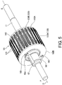
- FIG. 5 is a perspective view of the stator unit viewed from one P-side in the axial direction.
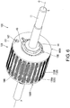
- FIG. 6 is a perspective view of the stator unit viewed from the other Q-side in the axial direction.
- FIG. 7 is an exploded perspective view of the stator viewed from one P-side in the axial direction.
- a large-diameter part is formed in an axial intermediate part of the hub shaft 11, and the stator 101 is attached to the outer periphery of the large-diameter part.
- stator 101 is positioned and fixed to the hub shaft 11 by a sleeve nut 42 and a fastening nut 44 (both are simply referred to as "nut” in some cases) via washers (plate-like members) 41, 43, 49 arranged at both ends of the stator 101 in the axial direction.
- the hub shaft 11, the stator 101 and the like constitute a stator unit 100.
- the inner ring of the bearing 35 is fitted into the outer periphery of the sleeve nut 42 disposed on one P-side in the axial direction of the stator unit 100.
- a connector 50 is arranged axially outside of the bearing 35, and a nut 51 is disposed on the axial outer side of the connector 50.
- the nut 51 is screwed to the hub shaft 11, and thereby the connector 50 is fixed to the hub shaft 11, and one end side of the hub shell 30 is rotatably supported by the hub shaft 11 via the bearing 35.
- another sleeve nut 45 is disposed on the other Q-side in the axial direction of the hub shaft 11, and the inner ring of the bearing 36 is fitted into the outer periphery of the sleeve nut 45.
- a cover 46 is arranged axially outside of the bearing 36, and a nut 47 is disposed in the inner peripheral part of the cover 46. The nut 47 is screwed to the hub shaft 11, and thereby the cover 46 is fixed to the hub shaft 11, and the other end side of the hub shell 30 is rotatably supported by the hub shaft 11 via the bearing 36.
- FIG. 8 is a perspective view showing a configuration of the stator 101.
- FIG. 9 is an exploded perspective view showing the configuration of the stator 101.
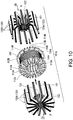
- FIG. 10 is an exploded perspective view of a stator body 101A that is a main part of the stator 101.
- the stator 101 includes the stator body 101A that is a main part, and a first holder 160A and a second holder 160B arranged on both sides in the axial direction of the stator body 101A. Both the holders 160A and 160B have the same configuration and are formed as an integrally molded product of resin.
- first holder 160A is disposed on the other Q-side in the axial direction and holds a front end 121a extending to the other Q-side in the axial direction of the first yoke 120A (described later) disposed on one P-side in the axial direction.
- second holder 160B is disposed on one P-side in the axial direction, and holds a front end 121a extending to one P-side in the axial direction of the second yoke 120B (described later) disposed on the other Q-side in the axial direction.
- the stator body 101A is configured by a tubular coil bobbin 110 made of a synthetic resin (made of a nonmagnetic material) through which the hub shaft 11 penetrates, a ring-like coil 140 wound around the coil bobbin 110, and a claw-pole-type stator core 120 assembled to surround the coil 140 inside.
- the hub shaft 11, the coil bobbin 110, the first yoke 120A, and the second yoke 120B are disposed coaxially.
- a plurality of first yokes 120A is arranged on one P-side in the axial direction and a plurality of second yokes 120B is arranged on the other Q-side in the axial direction as elements constituting the claw-pole-type stator core 120.
- the plurality of first yokes 120A and the plurality of second yokes 120B are disposed radially at a fixed interval in the circumferential direction and are alternately arranged in the circumferential direction.
- the outer peripheral parts of the yokes 120A, 120B are configured to face an inner peripheral surface 22a (see FIG. 3 ) of the permanent magnet 22 with a slight gap (air gap) therebetween.
- the number of the yokes 120A, 120B (the number of poles) is set in relation to the number of magnetic poles of the permanent magnet 22. In the embodiment, a total of 32 yokes that are 16 first yokes 120A and 16 second yokes 120B are arranged at a fixed interval. Although not shown, a wiring is connected to the coil 140, and the wiring is drawn outside along the hub shaft 11.
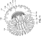
- FIG. 11 is a perspective view of the coil bobbin.
- the coil bobbin 110 has a cylindrical torso 111 having a coil 140 (see FIG. 10 ) wound on the outer periphery, and first flanges 112A and second flanges 112B arranged to project radially outward on the outer peripheries of the ends on one P-side and the other Q-side in the axial direction of the torso 111.
- a guide groove 113A is arranged by a rib-like wall on the axial outer end surface of the first flange 112A.
- an engagement groove 114A in communication with the guide groove 113A is arranged at a position corresponding to the guide groove 113A.
- the guide groove 113A and the engagement groove 114A are used for positioning and attaching the first yoke 120A to the coil bobbin 110.
- a positioning recess 117A which is formed in a V-shape when viewed from the axial direction is arranged by the rib-like wall next to the guide groove 113A of the axial outer end surface of the first flange 112A.
- a guide groove 113B is arranged by a rib-like wall on the axial outer end surface of the second flange 112B.
- an engagement groove 114B in communication with the guide groove 113B is arranged at a position corresponding to the guide groove 113B.
- the guide groove 113B and the engagement groove 114B are used for positioning and attaching the second yoke 120B to the coil bobbin 110.
- a positioning recess 117B which is formed in a V-shape when viewed from the axial direction is arranged by the rib-like wall next to the guide groove 113B of the axial outer end surface of the second flange 112B.
- support grooves 115A, 115B which are respectively located in the circumferential middle of the engagement grooves 114A, 114B and support the front ends of the opposite first yoke 120A and second yoke 120B are arranged on the outer peripheral surface of the first flange 112A and the outer peripheral surface of the second flange 112B.
- the circumferential position of the engagement groove 114A of the first flange 112A and the circumferential position of the support groove 115B of the second flange 112B matches each other, and the circumferential position of the engagement groove 114B of the second flange 112B and the circumferential position of the support groove 115A of the first flange 112A matches each other.
- the guide grooves 113A, 113B, the engagement grooves 114A, 114B, and the support grooves 115A, 115B are described later in detail.
- FIGS. 12(a) and 12(b) are diagrams of the stator body viewed from the axial direction;
- FIG. 12(a) is a diagram taken along an arrow EA in FIG. 10
- FIG. 12(b) is a diagram taken along an arrow EB in FIG. 10
- FIG. 13 is a diagram of the yokes and the coil bobbin viewed from one P-side in the axial direction, for illustrating arrangement angles of the first yoke and the second yoke of the stator body.
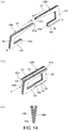
- FIGS. 14(a), 14(b), and 14(c) are diagrams for illustrating the arrangement angles of the first yoke and the second yoke;
- FIG. 14(a) is a perspective view showing a state before combining a pair of first yoke and second yoke
- FIG. 14(b) is a perspective view showing a state after combining the first yoke and the second yoke
- FIG. 14(c) is a diagram taken along an arrow F in FIG. 14(b)
- FIGS. 15(a), 15(b), and 15(c) are diagrams for illustrating a configuration of each yoke
- FIG. 15(a) is a perspective view of one plate-like member constituting the yoke
- FIG. 15(b) is a perspective view of the yoke configured by laminating plate-like members
- FIG. 15(c) is a perspective view of the yoke viewed from the connection part side.
- first yoke 120A and the second yoke 120B have the same structure and have a U-shape in a side view.
- the first yoke 120A has: an outer peripheral side magnetic pole part 121 located on the outer peripheral side of the coil 140 and extending a front end 121a from one end side (P-side) in the axial direction of the coil 140 to the other end side (Q-side) in the axial direction, an inner peripheral side magnetic pole part 123 located on the inner peripheral side of the coil 140 and extending a front end 123a from one end side (P-side) in the axial direction of the coil 140 to an intermediate position toward the other end side (Q-side) in the axial direction, and a connection part 122 extending linearly along the radial direction on one end side (P-side) in the axial direction of the coil 140 and connecting the base ends of the outer peripheral side magnetic pole part 121 and the inner peripheral side magnetic pole part 123.
- the second yoke 120B has: an outer peripheral side magnetic pole part 121 located on the outer peripheral side of the coil 140 and extending a front end 121a from the other end side (Q-side) in the axial direction of the coil 140 to one end side (P-side) in the axial direction, an inner peripheral side magnetic pole part 123 located on the inner peripheral side of the coil 140 and extending a front end from the other end side (Q-side) in the axial direction of the coil 140 to an intermediate position toward one end side (P-side) in the axial direction, and a connection part 122 extending linearly along the radial direction on the other end side (Q-side) in the axial direction of the coil 140 and connecting the base ends of the outer peripheral side magnetic pole part 121 and the inner peripheral side magnetic pole part 123.
- the radial outer peripheral edge of the outer peripheral side magnetic pole part 121 is disposed substantially parallel to the hub shaft 11.
- the outer peripheral side magnetic pole part 121 is formed in a tapered shape so that the radial inner peripheral edge thereof is closer to the radial outer peripheral edge toward the front end 121a.
- the radial inner peripheral edge and the radial outer peripheral edge are parallel to each other.
- the radial inner peripheral edge of the outer peripheral side magnetic pole part 121 is formed obliquely from the base end to the midway toward the front end 121a, and is formed parallel to the radial outer peripheral edge in the front end part.
- the radial inner peripheral edge and the radial outer peripheral edge of the inner peripheral side magnetic pole part 123 are formed parallel to the outer peripheral edge of the outer peripheral side magnetic pole part 121.
- the inner peripheral side magnetic pole part 123 of each of the yokes 120A, 120B is inserted into the inner periphery of the coil bobbin 110 so as to be located on the inner peripheral side of the coil 140, and is located between the inner peripheral surface of the torso 111 of the coil bobbin 110 and the outer peripheral surface of the hub shaft 11. Then, the hub shaft 11 penetrates a stator central hole 150 surrounded by the inner peripheral side magnetic pole parts 123 of the yokes 120A, 120B arranged densely in the circumferential direction (see FIG. 7 ).
- each of the first yoke 120A and the second yoke 120B is configured as a laminated yoke (laminate) in which a plurality of flat plate-like members 130 made of a magnetic material such as iron or the like in the plate thickness direction (the direction perpendicular to the radial direction of the coil 140).
- a material of the plate-like members 130 for example, a silicon steel plate (more specifically, a non-oriented silicon steel plate) having an oxide film formed on the surface thereof is employed.
- the plate-like members 130 are formed by punching a plate material by pressing or the like, and are configured as flat plates without being subjected to bending during formation of the yokes 120A, 120B.
- each plate-like member 130 is a substantially U-shaped iron piece, and has an outer peripheral side magnetic pole part 131 and an inner peripheral side magnetic pole part 133 forming two corresponding sides and a connection part 132 that is one side connecting the outer peripheral side magnetic pole part 131 and the inner peripheral side magnetic pole part 133.
- the basic shapes of the plate-like members 130 are the same; as shown in FIGS. 15(b) and 15(c) , a predetermined number of plate-like members 130 are laminated in the thickness direction, and thereby the outer peripheral side magnetic pole parts 121 of the yokes 120A, 120B are configured by the outer peripheral side magnetic pole parts 131 of the plate-like members 130.
- the inner peripheral side magnetic pole parts 133 of the yokes 120A, 120B are configured by the inner peripheral side magnetic pole parts 133 of the plate-like members 130.
- the connection parts 122 of the yokes 120A, 120B are configured by the connection parts 132 of the plate-like members 130.
- each of the yokes 120A, 120B is configured by laminating seven plate-like members 130.
- the first yokes 120A, 120B are assembled radially when viewed from the axial direction to the coil bobbin 110 so that the outer peripheral side magnetic pole part 121 comes to the outer diameter side.
- each of the yokes 120A, 120B is not simply arranged on a plane along the radial direction, but is disposed on a plane inclined to the radial direction (an actual arrangement surface of the yoke described later).
- the first yoke 120A and the second yoke 120B alternately line up in the circumferential direction and are disposed radially when viewed from the center of the coil 140. Accordingly, when the first yoke 120A and the second yoke 120B are simply arranged on a plane along the radial direction, the positions of the inner peripheral side magnetic pole parts 123 of the adjacent first yoke 120A and second yoke 120B deviate from each other in the circumferential direction. Then, the inner peripheral side magnetic pole parts 123 of the adjacent first yoke 120A and second yoke 120B cannot be magnetically connected in a one-to-one relationship.
- the front end 123a of the inner peripheral side magnetic pole part 123 of one first yoke 120A straddles and comes into contact with the front ends 123a of the inner peripheral side magnetic pole parts 123 of two adjacent second yokes 120B even when the inner peripheral side magnetic pole parts 123 of the first yoke 120A and the second yoke 120B are densely arranged in the circumferential direction.
- the front end 123a of the inner peripheral side magnetic pole part 123 of one second yoke 120B straddles and comes into contact with the front ends 123a of the inner peripheral side magnetic pole parts 123 of two adjacent first yokes 120A.
- the inner peripheral side magnetic pole part 123 of the first yoke 120A and the inner peripheral side magnetic pole part 123 of the second yoke 120B come into contact with each other in a one-to-two relationship.
- the inner peripheral side magnetic pole part 123 of the first yoke 120A and the inner peripheral side magnetic pole part 123 of the second yoke 120B come into contact with each other in a one-to-two relationship as descried above, the following problems may arise. That is, when the stator body 101A of the hub dynamo is actually assembled, the first yoke 120A is inserted into the coil bobbin 110 from one P-side in the axial direction and the second yoke 120B is inserted into the coil bobbin 110 from the other Q-side in the axial direction.
- the front end 123a of the inner peripheral side magnetic pole part 123 of the first yoke 120A comes into contact with only the front end 123a of the inner peripheral side magnetic pole part 123 of the second yoke 120B having a longer insertion direction dimension and does not come into contact with the front end 123a of the inner peripheral side magnetic pole part 123 of the other second yoke 120B, and a gap may be generated between the front end 123a of the inner peripheral side magnetic pole part 123 of the first yoke 120A and the front end 123a of the inner peripheral side magnetic pole part 123 of the other second yoke 120B.
- a gap is generated as described above in butted parts of the yokes 120A, 120B due to variations in the contacting surface caused by dimensional tolerances, the iron loss of the yokes 120A, 120B may increase and the performance may deteriorate.
- a circumferential center QA of the outer peripheral surface in the outer peripheral side magnetic pole part 121 of the first yoke hereinafter referred to as an arrangement position
- a plane including the central axis O of the hub shaft and the arrangement position QA of the first yoke is set as an arrangement reference surface SA0 of the first yoke.
- a plane including the arrangement position QA of the first yoke, parallel to the central axis O of the hub shaft, and inclined with respect to the arrangement reference surface SA0 of the first yoke by an angle ⁇ A to one side RA in the circumferential direction is set as an actual arrangement surface SA1 of the first yoke.
- the first yoke 120A is disposed on the actual arrangement surface SA1 of the first yoke.
- a plane including the central axis O of the hub shaft and the arrangement position QB of the second yoke is set as an arrangement reference surface SB0 of the second yoke.
- a plane including the arrangement position QB of the second yoke, parallel to the central axis O of the hub shaft, and inclined to the arrangement reference surface SB0 of the second yoke by an angle ⁇ B to the other side RB in the circumferential direction is set as an actual arrangement surface SB1 of the second yoke.
- the second yoke 120B is disposed on the actual arrangement surface SB1 of the second yoke.
- the guide grooves 113A, 113B of the first flange 112A and the second flange 112B of the coil bobbin 110 are also formed so that the extension directions of the guide grooves 113A, 113B are inclined at the same inclination angles ⁇ A, ⁇ B with respect to the radial direction.
- the engagement grooves 114A, 114B are formed so as to follow the inclinations of the guide grooves 113A, 113B.
- the support grooves 115A, 115B which accommodate and support the front ends 121a of the outer peripheral side magnetic pole parts 121 of the opposite yokes 120A, 120B are formed with some margin, so as to prioritize the dimensional precision of the engagement grooves 114B, 114A having corresponding positions in the circumferential direction.
- the first yoke 120A and the second yoke 120B are alternately inserted into the coil bobbin 110 from one P-side and the other Q-side in the axial direction. That is, the connection parts 122 of the yokes 120A, 120B are respectively fitted into the guide grooves 113A, 113B of the first flange 112A and the second flange 112B of the coil bobbin 110. In addition, the base ends of the outer peripheral side magnetic pole parts 121 of the yokes 120A, 120B are respectively fitted into the engagement grooves 114A, 114B of the first flange 112A and the second flange 112B of the coil bobbin 110.
- the front ends 121a of the outer peripheral side magnetic pole parts 121 of the yokes 120A, 120B are respectively accommodated in the support grooves 115A, 115B of the first flange 112A and the opposite second flange 112B of the coil bobbin 110.
- the inner peripheral side magnetic pole parts 123 of the yokes 120A, 120B are respectively inserted along the inner peripheral surface of the coil bobbin 110, and the front ends 123a of the inner peripheral side magnetic pole parts 123 of the yokes 120A, 120B are abutted and come into contact with each other. Thereby, the yokes 120A, 120B are mounted to surround the coil 140.
- the outer peripheral side magnetic pole parts 121 of the first yokes 120A and the outer peripheral side magnetic pole parts 121 of the second yokes 120B are alternately disposed at intervals in the circumferential direction on the outer peripheral side of the ring-like coil 140 wound around the torso 111 of the coil bobbin 110.
- the inner peripheral side magnetic pole parts 123 of the first yokes 120A and the inner peripheral side magnetic pole parts 123 of the second yokes 120B are disposed on the inner peripheral side of the ring-like coil 140 wound around the torso of the coil bobbin 110.
- the guide groove 113A of the first flange 112A of the coil bobbin 110 serves to position the first yoke 120A on the actual arrangement surface SA1 of the first yoke.
- the guide groove 113B of the second flange 112B serves to position the second yoke 120B on the actual arrangement surface SB1 of the second yoke.
- the plurality of yokes 120A, 120B is held so as not to rotate with respect to the coil bobbin 110.
- the support grooves 115A, 115B that are formed on the outer peripheries of the flanges 112A, 112B of the coil bobbin 110 and accommodate and support the front ends 121a of the outer peripheral side magnetic pole parts 121 of the opposite yokes 120A, 120B are formed with some margin with respect to the dimension of the front ends 121a of the outer peripheral side magnetic pole parts 121 of the yokes due to formation matters or the like. Therefore, it is found that there is a problem of abnormal noise generated at the front end 121a of the outer peripheral side magnetic pole part 121 of the yoke when the joining between the plate-like members 130 constituting the laminated yoke is weak. The principle of the generation of abnormal noise is described later.
- the holders 160A, 160B are arranged to prevent the generation of abnormal noise. Next, the holders 160A, 160B are described in detail.
- the first holder 160A is disposed on the axial outer side of the second flange 112B of the coil bobbin 110 located on the other Q-side in the axial direction so as to hold the front ends 121a extending to the other Q-side in the axial direction of the first yokes 120A.
- the second holder 160B is disposed on the axial outer side of the first flange 112A of the coil bobbin 110 located on the other Q-side in the axial direction so as to hold the front ends 121a extending to one P-side in the axial direction of the second yokes 120B.
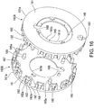
- FIG. 16 is a perspective view of the first holder 160A and the second holder 160B.
- the holders 160A, 160B have the same configuration.
- the holders 160A, 160B have a holder body part 161 being annular and plate-like and a plurality of pressing walls 162 which is arranged in the circumferential direction on the outer peripheral side of the axial inner side surface of the annular plate-like holder body part 161 and protrudes radially inward.
- the first holder 160A is disposed on the other Q-side in the axial direction with a side surface having the pressing walls 162 directed toward the second flange 112B of the coil bobbin 110.
- the second holder 160B is disposed on the one P-side in the axial direction with a side surface having the pressing walls 162 directed toward the first flange 112B of the coil bobbin 110.
- every other pair of pressing walls 162 (two pressing walls 162, 162) forms a holding groove 163 therebetween which clamps the front end 121a of the outer peripheral side magnetic pole part 121 of the yoke.
- a ridge 162a which is pressed in contact with the front end 121a of the outer peripheral side magnetic pole part 121 of the yoke is formed.
- the front end sides of the inner side surfaces of the pair of pressing walls 162 forming the holding groove 163 open in a C shape toward the axial direction (toward the flanges 112A, 112B of the coil bobbin) so as to facilitate the insertion of the front end 121a of the outer peripheral side magnetic pole part 121 of the yoke.
- a reinforcement wall 164 which connects the two pressing walls 162 by straddling the two pressing walls 162 is arranged.
- a positioning protrusion 165 being columnar and having a taper 165a at the front end is arranged on the axial inner side surface of the annular plate-like holder body part 161.
- three positioning protrusions 165 are arranged at intervals in the circumferential direction, but the number is not limited.
- the positioning protrusions 165 are fitted into V-shaped positioning recesses 117A, 117B on the outer side surfaces of the flanges 112A, 112B of the coil bobbin 110, to thereby position the holders 160A, 160B in the circumferential direction (the rotation direction) with respect to the coil bobbin 110.
- Coil drawing recesses 167, 168 (a coil drawing recess 167 at the outer peripheral edge and a coil drawing recess 168 at the inner peripheral edge) penetrating in the axial direction are respectively arranged at the outer peripheral edge 161a and the inner peripheral edge 161b of the annular plate-like holder body part 161.
- the start end or terminal end of the coil 140 is drawn out of the stator 101 through the coil drawing recesses 167, 168.
- each annular plate-like holder body part 161 an inner peripheral side flange wall 161c that is fastened by the sleeve nut 42 or the fastening nut 44 screwed to the hub shaft 11 is arranged.
- the inner peripheral side flange wall 161c is set to be thinner than the holder body part 161.
- the axial inner side surface of the inner peripheral side flange wall 161c is flush with the axial inner side surface of the holder body part 161, but the axial outer side surface of the inner peripheral side flange wall 161c is at a position that is more recessed than the axial outer side surface of the holder body part 161.
- a plurality of crushing protrusions 169 is arranged at intervals in the circumferential direction on the side surfaces of the axial outer sides of the inner peripheral side flange walls 161c of the holders 160A, 160B.
- the crushing protrusions 169 fulfil the function for absorbing the fastening force by being are crushed by the fastening force from the nuts 42, 44.
- FIG. 17 is a side view showing the arrangement of the front ends 121a of the outer peripheral side magnetic pole parts 121 of the first yoke 120A and the second yoke 120B with respect to the first holder 160A and the second holder 160B. As shown in FIGS. 8 and 17 , the front ends 121a of the outer peripheral side magnetic pole parts 121 of the yokes 120A, 120B are inserted into the holding grooves 163 of the holders 160A, 160B configured as described above.
- the front end 121a extending to the other Q-side in the axial direction of the outer peripheral side magnetic pole part 121 of the first yoke 120A passes through the support groove 115B of the second flange 112B of the coil bobbin 110 and is press-fitted into the holding groove 163 between the pair of pressing walls 162, 162 on the first holder 160A disposed on the axial outer side of the second flange 112B.
- the plurality of plate-like members 130 at the front end 121a of the outer peripheral side magnetic pole part 121 are clamped tightly in the lamination direction by the pair of pressing walls 162, 162.
- the front end 121a extending to one P-side in the axial direction of the outer peripheral side magnetic pole part 121 of the second yoke 120B passes through the support groove 115A of the first flange 112A of the coil bobbin 110 and is press-fitted into the holding groove 163 between the pair of pressing walls 162, 162 on the second holder 160B disposed on the axial outer side of the first flange 112A.
- the plurality of plate-like members 130 at the front end 121a of the outer peripheral side magnetic pole part 121 are clamped tightly in the lamination direction by the pair of pressing walls 162, 162.
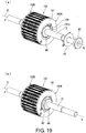
- FIGS. 18(a) and 18(b) are perspective views viewed from one P-side in the axial direction for illustrating a relationship between the stator 101 and the nut 42 and a washer 41 for fastening;
- FIG. 18(a) is a diagram showing a state before fastening the nut 42
- FIG. 18(b) is a diagram showing a state after fastening the nut 42.
- FIGS. 19(a) and 19(b) are perspective views viewed from the other Q-side in the axial direction for illustrating a relationship between the stator 101 and the nut 44 and two washers 43, 49 for fastening;
- FIG. 19(a) is a diagram showing a state before fastening the nut 44, and FIG.
- FIG. 19(b) is a diagram showing a state after fastening the nut 44.
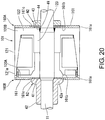
- FIG. 20 is a cross-sectional view for illustrating a relationship between the stator 101 and the nuts 42, 44 and the washers 41, 43, 49 for fastening.
- FIG. 21 is a partially enlarged view from an arrow direction N1 in FIG. 20 .
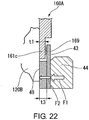
- FIG. 22 is a partially enlarged view from an arrow direction N2 of FIG. 20 .
- stator 101 (in which the holders 160A, 160B are disposed on both sides in the axial direction of the stator body 101A) is fixed to the hub shaft 11 by fastening the nuts 42, 44 screwed to the hub shaft 11.
- a fastening flange part 42a is arranged on the nut 42.
- the outer diameter of the fastening flange part 42a is set smaller than the diameter of the outer peripheral edge of the inner peripheral side flange wall 161c of the second holder 160B, and is set larger than the diameter of the circumference where the crushing protrusions 169 are disposed. Accordingly, when the nut 42 is fastened, the fastening flange part 42a of the nut 42 presses the inner peripheral side flange wall 161c while crushing the crushing protrusions 169 of the second holder 160B.
- the outer diameter of the washer 41 made of metal is set smaller than the inner diameter of the holder body part 161 of the second holder 160B.
- a thickness t2 of the washer 41 is set larger than a thickness t1 of the inner peripheral side flange wall 161c of the second holder 160B. Accordingly, when the nut 42 is fastened, a strong fastening force F1 can be directly applied to the axial outer side surface of the first yoke 120A (the base end of the inner peripheral side magnetic pole part 123) as a force F2 via the washer 41.
- the first washer 43 made of metal having a diameter larger than that of the nut 44 is disposed on the front side in the fastening direction of the nut 44.
- the outer diameter of the first washer 43 is set smaller than the diameter of the outer peripheral edge of the inner peripheral side flange wall 161c of the first holder 160A, and is set larger than the diameter of the circumference where the crushing protrusions 169 are disposed. Accordingly, when the nut 44 is fastened, the first washer 43 presses the inner peripheral side flange wall 161c while crushing the crushing protrusions 169 of the first holder 160A.
- the second washer 49 made of metal is disposed on the front side in the fastening direction of the first washer 43.
- the outer diameter of the second washer 49 is set smaller than the inner diameter of the holder body part 161 of the first holder 160A.
- a thickness t3 of the second washer 49 is set larger than the thickness t1 of the inner peripheral side flange wall 161c of the first holder 160A. Accordingly, when the nut 44 is fastened, the strong fastening force F1 is directly applied to the axial outer side surface (the base end inner of the inner peripheral side magnetic pole part 123) as the force F2 via the first washer 43 and the second washer 49.
- the inner peripheral side magnetic pole parts 123 of the adjacent yokes 120A, 120B densely line up and thus may interfere with each other. Therefore, in the embodiment, on at least one of one end side or the other end side in the circumferential direction of the inner peripheral side magnetic pole part 123, a notch part 135 that avoids interference between the inner peripheral ends of the adjacent yokes 120A, 120B is arranged.
- the inclination direction of the actual arrangement surface SA1 of the first yoke with respect to the arrangement reference surface SA0 of the first yoke 120A is defined as an inclination direction of the first yoke
- the inclination direction of the actual arrangement surface SB1 of the second yoke with respect to the arrangement reference surface SB0 of the second yoke 120B is defined as an inclination direction of the second yoke
- the seven laminated plate-like members 130 are denoted by reference numerals 130-1 to 130-7 that are respectively distinguished from the front side to the rear side in the inclination direction.
- the dimensions of the laminated plate-like members 130 are determined in a manner that the position of the radial inner peripheral end of the laminated plate-like member (for example, the plate-like member 130-1) located on the front side in the inclination direction of the yoke 120A (120B) is radially outside of the position of the radial inner peripheral end of the laminated plate-like member (for example, the plate-like member 130-7) located on the rear side in the inclination direction of the yoke 120A (120B).
- a radial dimension K1 of the plate-like member 130-1 located at the front end in the inclination direction of the first yoke 120A (120B) is set smaller by a dimension K3 than a radial dimension K2 of the plate-like member 130-2 located next to the plate-like member 130-1.
- the radial dimension K2 of the plate-like member 130-2 is set smaller by a dimension K5 than a radial dimension K4 of the plate-like members 130-3 to 130-7 located rearward of the plate-like member 130-2 in the inclination direction.
- the notch part 135 that avoids interference with the inner peripheral end of the inner peripheral side magnetic pole part 123 of the adjacent yoke 120A (120B) is secured at the front end in the inclination direction of the inner peripheral end of the inner peripheral side magnetic pole part 123 of the yoke 120A (120B).
- the radial dimensions of the plate-like members 130-2 to 130-7 may be set to be the same, and only the radial dimension K1 of the plate-like member 130-1 located at the foremost end in the inclination direction is set shorter than the radial dimensions of the other plate-like members 130-2 to 130-7.
- the radial dimensions of the plate-like members subsequent of the plate-like member 130-3 which is the third one from the plate-like member 130-1 located at the foremost end in the inclination direction may also be set in a manner that the radial dimension becomes longer in order of the plate-like members 130-3 to 130-7 located rearward in the inclination direction.
- the notch part 135 is arranged at the inner peripheral end on the front side in the inclination direction of the yoke 120A (120B), and thereby interference can be avoided even if the intervals between the plurality of yokes 120A (120B) lined up in the circumferential direction is dense. In other words, the arrangement interval of the yokes 120A (120B) can be reduced to arrange a large number of yokes 120A (120B).
- the electricity generation of the hub dynamo 10 configured as described above is performed in the following manner.
- an alternating magnetic flux is generated in the inner peripheral side magnetic pole parts 123 of the yokes 120A, 120B magnetically connecting the yokes 120A, 120B. Due to the alternating magnetic flux generated on the inner peripheral side of the coil, a current flows through the coil 140 of the stator 101 to generate electricity.
- each of the yokes 120A, 120B is configured as a laminate of a plurality of plate-like members 130 and thus generation of the eddy current can be suppressed.
- each of the yokes 120A, 120B is configured as a laminated yoke in which a plurality of plate-like members 130 (see FIG. 15 ) made of a magnetic material is laminated, the plate-like members 130 are usually joined by an adhesive.
- the N-pole and the S-pole of the permanent magnet 22 on the outer peripheral side of the yokes 120A, 120B if the joining strength between the plate-like members 130 is insufficient.
- one plate-like member 130 laminated on the outermost side may be separated although slightly. If the permanent magnet 22 moves more than a certain amount in this state, the adjacent S-pole approaches the one plate-like member 130 separated this time, and thereby the separated plate-like member 130 is excited to the N-pole as shown in FIG. 23(c) .
- the plate-like member 130 at the end in the lamination direction can be prevented from being separated from the other plate-like members 130 even if a magnetic repulsive force is generated between the plate-like members 130 of the laminated yoke.
- the front end 121a extending to the other Q-side in the axial direction of the outer peripheral side magnetic pole part 121 of the first yoke 120A which holds one P-end side (base end side) in the axial direction by the first flange 112A of the coil bobbin 110 is supported by the first holder 160A disposed on the axial outer side of the second flange 112B of the coil bobbin 110.
- the front end 121a extending to one P-side in the axial direction of the outer peripheral side magnetic pole part 121 of the second yoke 120B which holds the other Q-end side (base end side) in the axial direction by the second flange 112B of the coil bobbin 110 is supported by the second holder 160B disposed on the axial outer side of the first flange 112A of the coil bobbin 110.
- the holders 160A, 160B that hold the front ends 121a of the outer peripheral side magnetic pole parts 121 are disposed separately from the flanges 112A, 112B of the coil bobbin 110 on a side opposite to the side where the yokes 120A, 120B are disposed.
- the front ends 121a of the outer peripheral side magnetic pole parts 121 of the yokes 120A, 120B can be stably and tightly held as long as the precision of the holders 160A, 160B is secured.
- the pair of pressing walls 162, 162 that holds the front ends 121a of the outer peripheral side pole parts 121a of the yokes 120A, 120B is reinforced by the reinforcing wall 164 disposed on the inner peripheral side of the pressing walls 162, 162, the clamping force applied to the front ends 121a of the outer peripheral side magnetic pole parts 121 of the yokes 120A, 120B can be set strong.
- the reinforcing wall 164 is disposed across the inner peripheral side of the pair of pressing walls 162, 162, and thereby it is also possible to prevent the front ends 121a of the outer peripheral side magnetic pole parts 121 of the yokes 120A, 120B from deviating inward in the radial direction.
- the thicknesses t2, t3 of the washers 41, 49 that transmit the fastening force of the nuts 42, 44 to both ends of the stator 101 are set larger than the thickness t1 of the inner peripheral side flange walls 161c of the holders 160A, 160B. Thereby, the fastening force from the nuts 42, 44 can be directly applied to the base ends of the inner peripheral side magnetic pole parts 123 of the yokes 120A, 120B.
- the front end 123a of the inner peripheral side magnetic pole part 123 of the first yoke 120A and the front end 123a of the inner peripheral side magnetic pole part 123 of the second yoke 120B can be brought into firm contact with each other, and the first yoke 120A and the second yoke 120B can be magnetically coupled in a satisfactory manner.
- the crushing protrusions 169 are crushed during fastening of the nuts 42, 44 with respect to the resin holders 160A, 160B, and thereby an excessive fastening force can be prevented from acting on the holder body part 161. Therefore, the holders 160A, 160B can be fastened and fixed appropriately, and it is also unnecessary to set a small fastening force from the nuts 42, 44 just because there are the holders 160A, 160B made of resin. In other words, it is possible to increase the magnetic coupling between the first yoke 120A and the second yoke 120B by setting a large fastening force from the nuts 42, 44.
- the coil drawing recesses 167, 168 are arranged at the outer peripheral edge 161a and the inner peripheral edge 161b of the holders 160A, 160B, the start end or terminal end of the coil 140 can be drawn out smoothly.
- the first yoke 120A and the second yoke 120B are not disposed on the planes along the radial direction (the arrangement reference surfaces SA0, SB0 of the yokes) but on the planes inclined with respect to the radial direction (the actual arrangement surfaces SA1, SAB1 of the yokes). Therefore, the inner peripheral side magnetic pole part 123 of the first yoke 120A and the inner peripheral side magnetic pole part 123 of the second yoke 120B can be brought into contact with each other in a one-to-one relationship.
- the yokes can be positioned on the planes inclined with respect to the radial direction (the actual arrangement surfaces SA1, SB1 of the yokes) by engaging the axial ends of the yokes 120A, 120B with the guide grooves 113A, 113B or the engagement grooves 114A, 114B of the flanges 112A, 112B of the coil bobbin 110. Accordingly, the positional relationship between the coil 140 wound around the coil bobbin 110 and the yokes 120A, 120B can be appropriately determined by assembling the yokes 120A, 120B to the coil bobbin 110.
- the present invention is not limited to the above embodiment, and includes various modifications applied to the above embodiment without departing from the gist of the present invention.
- the lamination number of the plate-like members 130 when constituting the yokes 120A, 120B may be arbitrarily determined, and the number of the yokes 120A, 120B is not limited to 32 either.
- the number of the stator 101 is not limited to one, and two or three stators 101 may be disposed in line on the hub shaft 11 to constitute the stator unit. In this case, an alternating current with deviating phases can be generated by deviating the phases of the two stators 101.
- the holders 160A, 160B are configured separately from the flanges 112A, 112B of the coil bobbin 110, but the holders 160A, 160B may also be formed integrally with the flanges 112A, 112B of the coil bobbin 110.
Landscapes
- Engineering & Computer Science (AREA)
- Power Engineering (AREA)
- Iron Core Of Rotating Electric Machines (AREA)
- Permanent Magnet Type Synchronous Machine (AREA)
Abstract
Description
- The present invention relates to a hub dynamo.
- Electricity generator that generate electricity by rotation of a wheel to supply electrical power to headlights or taillights of a bicycle are widely used. There are various types of electricity generators, and a so-called hub dynamo that is attached to a hub shaft is known.
In general, the hub dynamo is equipped with a rotor having a permanent magnet on the wheel side, and the rotor rotates around a stator arranged on the hub shaft side, to thereby generate electricity with a coil equipped in the stator. - As the stator in the hub dynamo, a claw-pole-type state in which first yokes and second yokes are assembled to a coil bobbin is known. In this stator, a plurality of first yokes and a plurality of second yokes are respectively disposed on one side and the other side in the axial direction of the coil bobbin around which the coil is wound. Besides, outer peripheral side magnetic pole parts (teeth parts) of the first yokes and outer peripheral side magnetic pole parts (teeth parts) of the second yokes are alternately arranged in the circumferential direction.
- For example, in the hub dynamo described in patent literature 1, each yoke of the first yokes and the second yokes is configured as a laminated yoke in which a plurality of flat plate-like members made of a magnetic material is laminated in a direction perpendicular to the radial direction of the coil. Besides, the first yoke and the second yoke respectively have a U-shape in a side view.
- That is, the first yoke has a U-shape in a side view, which includes: an outer peripheral side magnetic pole part (teeth part) located on the outer peripheral side of the coil and extending the front end from one end side in the axial direction of the coil to the other end side in the axial direction, an inner peripheral side magnetic pole part located on the inner peripheral side and extending the front end from one end side in the axial direction of the coil to an intermediate position toward the other end side in the axial direction, and a connection part extending linearly along the radial direction on one end side in the axial direction of the coil and connecting the base ends of the outer peripheral side magnetic pole part and the inner peripheral side magnetic pole part.
- In addition, the second yoke has a U-shape in a side view, which includes: an outer peripheral side magnetic pole part (teeth part) located on the outer peripheral side of the coil and extending the front end from the other end side in the axial direction of the coil to one end side in the axial direction, an inner peripheral side magnetic pole part located on the inner peripheral side and extending the front end from the other end side in the axial direction of the coil to an intermediate position toward one end side in the axial direction, and a connection part extending linearly along the radial direction on the other end side in the axial direction of the coil and connecting the base ends of the outer peripheral side magnetic pole part and the inner peripheral side magnetic pole part.
- Besides, on the inner peripheral side of the coil, the front end of the inner peripheral side magnetic pole part of the first yoke and the front end of the inner peripheral side magnetic pole part of the second yoke are brought into contact with each other, and thereby the first yoke and the second yoke are magnetically connected.
- Patent literature 1: Japanese Patent Laid-open No.
2016-41591 - Meanwhile, when each yoke is configured as a laminated yoke in which a plurality of plate-like members made of a magnetic material is laminated, the plate-like members are usually joined by an adhesive. However, there is a possibility that abnormal noise is generated due to alternate rotation movement of N-poles and S-poles of a permanent magnet on the outer peripheral side of the yoke if the joining strength between the plate-like members is insufficient.
- That is, for example, when the N-pole of the permanent magnet passes through the outer peripheral side of the yoke, the outer peripheral end (the outer peripheral side magnetic pole part) of the yoke is excited to the S-pole. Then, the laminated plate-like members are all excited to the S-pole, and thereby a repulsive force is generated between the plate-like members and the plate-like members tend to be separated from each other. When the joining strength between the plate-like members is weak, for example, one plate-like member laminated on the outermost side may be separated although slightly. If the permanent magnet moves more than a certain amount in this state, the adjacent S-pole approaches the one plate-like member separated, and thereby the separated plate-like member is excited to the N-pole. When the separated plate-like member is excited to the N-pole, an attractive force is generated between the separated plate-like member and the remaining plate-like members excited to the S-pole, and the separated plate-like member is attracted and slammed against the remaining plate-like members. At that time, there is a possibility that the abnormal noise caused by collision is generated.
- Therefore, the present invention is accomplished in view of the above circumstances, and an objective thereof is to provide a hub dynamo capable of resolving the generation of abnormal noise from a laminated yoke due to rotation.
- In order to solve the above problems, a hub dynamo of the present invention includes: a rotor having a hub shell rotating together with a wheel and a permanent magnet circumferentially disposed on the inner periphery of a torso of the hub shell, and a stator non-rotatably fixed to a hub shaft supporting the wheel to be rotatable, disposed on the inner peripheral side of the permanent magnet while being accommodated in the hub shell, and having a ring-like coil that outputs an alternating current by rotation of the rotor; the stator has a plurality of first yokes and a plurality of second yokes plurality disposed on one side in the axial direction and the other side in the axial direction to surround the ring-like coil, and radially disposed at intervals in the circumferential direction and alternately disposed in the circumferential direction, and also has a first holder disposed on the other side in the axial direction to hold the other end side in the axial direction of the first yoke and a second holder disposed on one side in the axial direction to hold one side in the axial direction of the second yoke; the first yoke has: an outer peripheral side magnetic pole part located on the outer peripheral side of the coil and extending the front end from one end side in the axial direction to the other end side in the axial direction of the coil, an inner peripheral side magnetic pole part located on the inner peripheral side of the coil and extending the front end from one end side in the axial direction of the coil to an intermediate position toward the other end side in the axial direction, and a connection part extending linearly on one end side in the axial direction of the coil and connecting the base ends of the outer peripheral side magnetic pole part and the inner peripheral side magnetic pole part; the second yoke has: an outer peripheral side magnetic pole part located on the outer peripheral side of the coil and extending the front end from the other end side in the axial direction to one end side in the axial direction of the coil, an inner peripheral side magnetic pole part located on the inner peripheral side of the coil and extending the front end from the other end side in the axial direction of the coil to an intermediate position toward one end side in the axial direction, and a connection part extending linearly on the other end side in the axial direction of the coil and connecting the base ends of the outer peripheral side magnetic pole part and the inner peripheral side magnetic pole part; the first yoke and the second yoke are respectively configured as a laminated yoke in which a plurality of flat plate-like members made of a magnetic material is laminated in a direction perpendicular to the radial direction of the coil, and the front end of the inner peripheral side magnetic pole part of the first yoke and the front end of the inner peripheral side magnetic pole part of the second yoke come into contact with each other on the inner peripheral side of the coil; furthermore, the front end of the outer peripheral side magnetic pole of the first yoke is disposed between a pair of adjacent pressing walls among a plurality of pressing walls arranged in the circumferential direction on the first holder, and thereby the plurality of plate-like members at the front end of the outer peripheral side magnetic pole are clamped tightly in the lamination direction by the pair of pressing walls, and the front end of the outer peripheral side magnetic pole of the second yoke is disposed between a pair of adjacent pressing walls among a plurality of pressing walls arranged in the circumferential direction on the second holder, and thereby the plurality of plate-like members at the front end of the outer peripheral side magnetic pole are clamped tightly in the lamination direction by the pair of pressing walls.
- In this configuration, the front end of the outer peripheral side magnetic pole part of the yoke is clamped tightly in the lamination direction of the plate-like members by the holder. Accordingly, the plate-like member at the end in the lamination direction can be prevented from being separated from the other plate-like members even if a magnetic repulsive force is generated between the plate-like members of the laminated yoke. As a result, it is possible to eliminate a phenomenon that the plate-like member at the end in the lamination direction is separated from the other plate-like members according to the rotation of the permanent magnet and then is magnetically attracted and slammed against the other plate-like members, and it is possible to resolve the generation of abnormal noise. In addition, since the front end of the outer peripheral side magnetic pole part of the yoke is clamped in the state that the plate-like members are in close contact with each other, it is also possible to omit a process for adhering the plate-like members using an adhesive, and the manufacturing process is simplified.
- In the hub dynamo of the present invention, during arrangement of the first yoke and the second yoke, the arrangement position of the first yoke and the arrangement position of the second yoke are alternately set at intervals in the circumferential direction on the outer peripheral surface of the stator; a plane including the central axis of the hub shaft and the circumferential center on the outer peripheral surface side of the outer peripheral side magnetic pole part of the first yoke is set as an arrangement reference surface of the first yoke, and a plane inclined to one side in the circumferential direction with respect to the arrangement reference surface of the first yoke is set as an actual arrangement surface of the first yoke, and thereby the first yoke is arranged on the actual arrangement surface of the first yoke; a plane including the central axis of the hub shaft and the circumferential center on the outer peripheral surface side of the outer peripheral side magnetic pole part of the second yoke is set as an arrangement reference surface of the second yoke, and a plane inclined to the other side in the circumferential direction with respect to the arrangement reference surface of the second yoke is set as an actual arrangement surface of the second yoke, and thereby the second yoke is arranged on the actual arrangement surface of the second yoke; and the front end of the inner peripheral side magnetic pole part of the first yoke and the front end of the inner peripheral side magnetic pole part of the second yoke come into contact with each other on an intersection line between the actual arrangement surface of the first yoke and the actual arrangement surface of the second yoke.
- In this configuration, since the yokes are disposed not on the plane along the radial direction but on the plane inclined with respect to the radial direction (the actual arrangement plane of the yoke), the front end of the inner peripheral side magnetic pole part of the first yoke and the front end of the inner peripheral side magnetic pole part of the second yoke can be brought into contact with each other in a one-to-one relationship. Accordingly, it is possible to eliminate a gap generated on the contacting surface between the first yoke and the second yoke due to variations caused by dimensional tolerances of the yoke or the like, and it is possible to increase the degree of close contact of the contacting surface. As a result, the magnetic connection between the yokes can be stabilized and the iron loss can be reduced.
- In the hub dynamo of the present invention, the stator has a coil bobbin holding the ring-like coil, and the coil bobbin has: a torso around which the coil is wound, a first flange disposed on one side in the axial direction of the torso and holding one end side in the axial direction of the first yoke, and a second flange disposed on the other side in the axial direction of the torso and holding the other end side in the axial direction of the second yoke; the first holder disposed on the other side in the axial direction has: a plate-like holder body part being annular and disposed on the axial outer side of the second flange of the coil bobbin, and a plurality of pressing walls arranged in the circumferential direction on the outer peripheral side of the axial inner side surface of the annular plate-like holder body part and protruding toward one side in the axial direction; the second holder disposed on one side in the axial direction has: a plate-like holder body part being annular and disposed on the axial outer side of the first flange of the coil bobbin, and a plurality of pressing walls arranged in the circumferential direction on the outer peripheral side of the axial inner side surface of the annular plate-like holder body part and protruding toward the other side in the axial direction; the front end of the outer peripheral side magnetic pole part of the first yoke is clamped between every other pair of pressing walls among the plurality of pressing walls arranged in the circumferential direction of the first holder, and the front end of the outer peripheral side magnetic pole part of the second yoke is clamped between every other pair of pressing walls among the plurality of pressing walls arranged in the circumferential direction of the second holder.
- In this configuration, the front end extending to the other end side in the axial direction of the outer peripheral side magnetic pole part of the first yoke which holds one end side in the axial direction by the first flange of the coil bobbin can be supported by the first holder disposed on the axial outer side of the second flange of the coil bobbin. In addition, the front end extending to one end side in the axial direction of the outer peripheral side magnetic pole part of the second yoke which holds the other end side in the axial direction by the second flange of the coil bobbin can be supported by the second holder disposed on the axial outer side of the first flange of the coil bobbin. In other words, the holder that holds the front end of the outer peripheral side magnetic pole part is disposed separately from the flange of the coil bobbin on a side opposite to the side where the respective yokes are disposed. Therefore, regardless of the processing precision of the flange of the coil bobbin, the front end of the outer peripheral side magnetic pole part of the yoke can be stably and tightly held as long as the precision of the holder is secured.
- In the hub dynamo of the present invention, on the inner peripheral sides of the pressing walls forming a pair of the first holder and the second holder, a reinforcement wall that connects the two pressing walls by straddling the two pressing walls is arranged.
- In this configuration, since the pair of pressing walls is reinforced by the reinforcement wall, the clamping force applied to the front end of the outer magnetic pole part of the yoke can be set strong. In addition, the reinforcing wall is disposed straddling the inner peripheral sides of the pair of pressing walls, and thereby it is also possible to prevent the front end of the outer peripheral side magnetic pole part of the yoke from deviating inward in the radial direction.
- In the hub dynamo of the present invention, the first holder and the second holder are made of resin, and a plurality of protrusions is arranged, on the side surface of the inner peripheral side of the axial outer side of each annular plate-like holder body part of the first holder and the second holder, which absorbs a fastening force from a nut screwed to the hub shaft by being crushed by the nut when the first yoke and the second yoke are fastened in the axial direction by the nut.
- In this configuration, the fastening force from the nut can be directly applied to the yoke. Therefore, the front end of the inner peripheral side magnetic pole part of the first yoke and the front end of the inner peripheral side magnetic pole part of the second yoke can be brought into firm contact with each other, and the first and second yokes can be magnetically coupled in a satisfactory manner. In addition, the protrusions are crushed during fastening of the nut with respect to the resin holder, and thereby an excessive fastening force can be prevented from acting on the holder body part. Thereby, the holder can be fastened and fixed appropriately, and it is also unnecessary to set a small fastening force from the nut just because there is a resin holder. In other words, it is possible to increase the magnetic coupling between the first yoke and the second yoke by setting a large fastening force from the nut to be large.
- In the hub dynamo of the present invention, coil drawing recesses penetrating in the axial direction are arranged at the inner peripheral edge and the outer peripheral edge of the annular plate-like holder body part.
- In this configuration, the start end or terminal end of the coil can be smoothly drawn outside.
- According to the hub dynamo of the present invention, even if a magnetic repulsive force is generated between the plate-like members of the laminated yoke, the plate-like member at the end in the lamination direction can be prevented from being separated from the other plate-like members. As a result, it is possible to eliminate a phenomenon that the plate-like member at the end in the lamination direction is separated from the other plate-like members according to the rotation of the permanent magnet and then is magnetically attracted and slammed against the other plate-like members, and it is possible to resolve the generation of abnormal noise.
-
-
FIG. 1 is an attachment schematic view of a hub dynamo in an embodiment of the present invention. -
FIG. 2 is an external perspective view of the hub dynamo in the embodiment of the present invention. -
FIG. 3 is a cross-sectional view of the hub dynamo in the embodiment of the present invention. -
FIG. 4 is a side view of a stator unit constituting the hub dynamo in the embodiment of the present invention. -
FIG. 5 is a perspective view of the stator unit constituting the hub dynamo in the embodiment of the present invention, the stator unit being viewed from one P-side in the axial direction. -
FIG. 6 is a perspective view of the stator unit constituting the hub dynamo in the embodiment of the present invention, the stator unit being viewed from the other Q-side in the axial direction. -
FIG. 7 is an exploded perspective view of the stator unit constituting the hub dynamo in the embodiment of the present invention, the stator unit being viewed from one P-side in the axial direction. -
FIG. 8 is a perspective view of a stator constituting the hub dynamo in the embodiment of the present invention. -
FIG. 9 is an exploded perspective view of the stator constituting the hub dynamo in the embodiment of the present invention. -
FIG. 10 is an exploded perspective view of a stator body which is a main part of the stator constituting the hub dynamo in the embodiment of the present invention. -
FIG. 11 is a perspective view of a coil bobbin of the stator constituting the hub dynamo in the embodiment of the present invention. -
FIGS. 12(a) and 12(b) are diagrams of the stator body constituting the hub dynamo in the embodiment of the present invention, the stator body being viewed from the axial direction;FIG. 12(a) is a diagram taken along an arrow EA inFIG. 10 , andFIG. 12(b) is a diagram taken along an arrow EB inFIG. 10 . -
FIG. 13 is a diagram of yokes and the coil bobbin viewed from one P-side in the axial direction, for illustrating arrangement angles of a first yoke and a second yoke of the stator body constituting the hub dynamo in the embodiment of the present invention. -
FIGS. 14(a), 14(b), and 14(c) are diagrams for illustrating the arrangement angles of the first yoke and the second yoke of the stator constituting the hub dynamo in the embodiment of the present invention;FIG. 14(a) is a perspective view showing a state before combining a pair of first yoke and second yoke,FIG. 14(b) is a perspective view showing a state after combining the first yoke and the second yoke, andFIG. 14(c) is a diagram taken along an arrow F inFIG. 14(b) . -
FIGS. 15(a), 15(b), and 15(c) are diagrams for illustrating a configuration of each yoke of the stator constituting the hub dynamo in the embodiment of the present invention;FIG. 15(a) is perspective view of one plate-like member constituting the yoke,FIG. 15(b) is a perspective view of the yoke configured by laminating plate-like members, andFIG. 15(c) is a perspective view of the yoke viewed from the connection part side. -
FIG. 16 is a perspective view of a first holder and a second holder of the stator constituting the hub dynamo in the embodiment of the present invention. -
FIG. 17 is a side view showing the arrangement of front ends of outer peripheral side magnetic pole parts of the first yoke and the second yoke with respect to the first holder and the second holder of the stator constituting the hub dynamo in the embodiment of the present invention. -
FIGS. 18(a) and 18(b) are diagrams viewed from one P-side in the axial direction for illustrating a relationship between the stator constituting the hub dynamo in the embodiment of the present invention and a nut and a washer for fastening;FIG. 18(a) is a diagram showing a state before fastening the nut, andFIG. 18(b) is a diagram showing a state after fastening the nut. -
FIGS. 19(a) and 19(b) are diagrams viewed from the other Q-side in the axial direction for illustrating a relationship between the stator constituting the hub dynamo in the embodiment of the present invention and a nut and washers for fastening;FIG. 19(a) is a diagram showing a state before fastening the nut, andFIG. 19(b) is a diagram showing a state after fastening the nut. -
FIG. 20 is a cross-sectional view for illustrating the relationship between the stator constituting the hub dynamo in the embodiment of the present invention and the nut and washer for fastening. -
FIG. 21 is a partially enlarged view taken along an arrow direction N1 inFIG. 20 . -
FIG. 22 is a partially enlarged view taken along an arrow direction N2 inFIG. 20 . -
FIGS. 23(a)-(d) are a diagram for illustrating a principle of the generation of abnormal noise from a laminated yoke due to rotation in order of (a) to (d). - Next, an embodiment of the present invention is described with reference to the diagrams.
-
FIG. 1 is an attachment schematic view of ahub dynamo 10. Besides, in the following description, a case is described in which thehub dynamo 10 of the present invention is attached to ahub shaft 11 of a bicycle 1 and electrical power is supplied to aheadlamp 4 of the bicycle 1. Theheadlight 4 uses an LED lamp as a lamp instead of using a filament-type bulb. - As shown in
FIG. 1 , afront wheel 5 of the bicycle 1 is rotatably pivoted via thehub shaft 11 by afront fork 3 constituting a part of a frame. Both sides of thehub shaft 11 are non-rotatably fastened and fixed to thefront fork 3 by a nut (not shown) or the like. Thehub dynamo 10 is attached coaxially to thehub shaft 11 at most of the axial center of thehub shaft 11. Thehub dynamo 10 is arranged to supply electrical power to theheadlight 4 disposed on a lateral side of thefront wheel 5. - The
hub dynamo 10 includes a rotor 20 (described later) which is connected to aspoke 2 of thefront wheel 5 and rotates together with thefront wheel 5 around thehub shaft 11, and a stator 101 (described later) which is non-rotatably attached to thehub shaft 11 in a state of being located on the inner peripheral side of therotor 20.
Hereinafter, the axial direction of a central axis O of thehub shaft 11 is simply referred to as an axial direction, the direction perpendicular to the axial direction is referred to as a radial direction, and the direction around the central axis O is referred to as a circumferential direction. Besides, in a part of thehub shaft 11 located axially outside of a part of thehub shaft 11 to which at least a stator 101 (described later) is attached, a male screw part (not shown) for fixing thehub dynamo 10 to thefront fork 3 is formed. -
FIG. 2 is an external perspective view of thehub dynamo 10.FIG. 3 is a cross-sectional view of thehub dynamo 10. - As shown in
FIGS. 2 and3 , therotor 20 is mainly configured by ahub shell 30. Thehub shell 30 includes a cylindrical torso (tube) 31 and asecond end plate 33 on the other Q-side in the axial direction of the torso 31 (the right side inFIG. 3 ) which are integrally formed in a substantially bottomed cylindrical shape, and afirst end plate 32 which blocks an opening on one P-side in the axial direction of the torso 31 (the left side inFIG. 3 ). Thefirst end plate 32 is press-fitted and fixed to thetorso 31. - On the outer periphery of the
hub shell 30 on the axial P-side in the axial direction and the other Q-side in the axial direction,flange parts 34 projecting radially outward are formed. In eachflange part 34, a plurality ofsupport holes 34a penetrating in the axial direction is formed at equal intervals in the circumferential direction. - As shown in
FIG. 1 , inner ends of a plurality ofspokes 2 extending from arim 5a of thefront wheel 5 toward the inner diameter side are engaged with thesupport holes 34a. Besides, the support holes 34a of the left andright flange parts 34 are disposed with a phase deviation in the circumferential direction by a half pitch. - Outer rings of
bearings first end blade 32 and the inner periphery of thesecond end blade 33. Then, therotor 20 mainly configured by thehub shell 30 is rotatably supported by thehub shaft 11 via thebearings hub shaft 11 together with the rotation of thefront wheel 5. That is, therotor 20 functions as a hub that supports thefront wheel 5 so that thefront wheel 5 is rotatable. - On the inner periphery of the
torso 31 of thehub shell 30, apermanent magnet 22 formed by, for example, ferrite or the like is disposed via aring yoke 21 being cylindrical. Thering yoke 21 is made of a magnetic metal material (for example, iron). By thering yoke 21 being made of iron for example, thehub shell 30 can be made of aluminum to reduce weight. Thepermanent magnet 22 is disposed in close contact with the inner periphery of thering yoke 21 and is attached by an adhesive or the like. Thepermanent magnet 22 is disposed in a cylindrical shape along the inner peripheral surface of thetorso 31, and thereby thepermanent magnet 22 covers the entire outer peripheral surface of thestator 101. - Besides, the
permanent magnet 22 is incorporated into the inner periphery of thetorso 31 of thehub shell 30 in a state of being divided into a plurality of parts in the circumferential direction. On the inner peripheral surface of thepermanent magnet 22 disposed in a cylindrical shape, magnetic poles of the N-pole and S-pole are alternately magnetized along the circumferential direction at equal intervals and face the outer peripheral parts of afirst yoke 120A and asecond yoke 120B described later. -
FIG. 4 is a side view of a stator unit constituting the hub dynamo.FIG. 5 is a perspective view of the stator unit viewed from one P-side in the axial direction.FIG. 6 is a perspective view of the stator unit viewed from the other Q-side in the axial direction.FIG. 7 is an exploded perspective view of the stator viewed from one P-side in the axial direction. - As shown in
FIG. 3 , a large-diameter part is formed in an axial intermediate part of thehub shaft 11, and thestator 101 is attached to the outer periphery of the large-diameter part. - As shown in
FIGS. 4-7 , thestator 101 is positioned and fixed to thehub shaft 11 by asleeve nut 42 and a fastening nut 44 (both are simply referred to as "nut" in some cases) via washers (plate-like members) 41, 43, 49 arranged at both ends of thestator 101 in the axial direction. Thehub shaft 11, thestator 101 and the like constitute astator unit 100. - As shown in
FIG. 3 , the inner ring of thebearing 35 is fitted into the outer periphery of thesleeve nut 42 disposed on one P-side in the axial direction of thestator unit 100. Aconnector 50 is arranged axially outside of thebearing 35, and anut 51 is disposed on the axial outer side of theconnector 50. Thenut 51 is screwed to thehub shaft 11, and thereby theconnector 50 is fixed to thehub shaft 11, and one end side of thehub shell 30 is rotatably supported by thehub shaft 11 via thebearing 35. - In addition, another
sleeve nut 45 is disposed on the other Q-side in the axial direction of thehub shaft 11, and the inner ring of thebearing 36 is fitted into the outer periphery of thesleeve nut 45. Acover 46 is arranged axially outside of thebearing 36, and a nut 47 is disposed in the inner peripheral part of thecover 46. The nut 47 is screwed to thehub shaft 11, and thereby thecover 46 is fixed to thehub shaft 11, and the other end side of thehub shell 30 is rotatably supported by thehub shaft 11 via thebearing 36. - Next, details of the
stator 101 are described. -
FIG. 8 is a perspective view showing a configuration of thestator 101.FIG. 9 is an exploded perspective view showing the configuration of thestator 101.FIG. 10 is an exploded perspective view of astator body 101A that is a main part of thestator 101. - As shown in
FIGS. 8 and9 , thestator 101 includes thestator body 101A that is a main part, and afirst holder 160A and asecond holder 160B arranged on both sides in the axial direction of thestator body 101A. Both theholders - The point to be noted here is that the
first holder 160A is disposed on the other Q-side in the axial direction and holds afront end 121a extending to the other Q-side in the axial direction of thefirst yoke 120A (described later) disposed on one P-side in the axial direction. In addition, thesecond holder 160B is disposed on one P-side in the axial direction, and holds afront end 121a extending to one P-side in the axial direction of thesecond yoke 120B (described later) disposed on the other Q-side in the axial direction. - As shown in
FIG. 10 , thestator body 101A is configured by atubular coil bobbin 110 made of a synthetic resin (made of a nonmagnetic material) through which thehub shaft 11 penetrates, a ring-like coil 140 wound around thecoil bobbin 110, and a claw-pole-type stator core 120 assembled to surround thecoil 140 inside. Thehub shaft 11, thecoil bobbin 110, thefirst yoke 120A, and thesecond yoke 120B are disposed coaxially. - Here, a plurality of
first yokes 120A is arranged on one P-side in the axial direction and a plurality ofsecond yokes 120B is arranged on the other Q-side in the axial direction as elements constituting the claw-pole-type stator core 120. The plurality offirst yokes 120A and the plurality ofsecond yokes 120B are disposed radially at a fixed interval in the circumferential direction and are alternately arranged in the circumferential direction. Besides, the outer peripheral parts of theyokes peripheral surface 22a (seeFIG. 3 ) of thepermanent magnet 22 with a slight gap (air gap) therebetween. - The number of the
yokes permanent magnet 22. In the embodiment, a total of 32 yokes that are 16first yokes 120A and 16second yokes 120B are arranged at a fixed interval. Although not shown, a wiring is connected to thecoil 140, and the wiring is drawn outside along thehub shaft 11. -
FIG. 11 is a perspective view of the coil bobbin. - As shown in
FIG. 11 , thecoil bobbin 110 has acylindrical torso 111 having a coil 140 (seeFIG. 10 ) wound on the outer periphery, andfirst flanges 112A andsecond flanges 112B arranged to project radially outward on the outer peripheries of the ends on one P-side and the other Q-side in the axial direction of thetorso 111. - A
guide groove 113A is arranged by a rib-like wall on the axial outer end surface of thefirst flange 112A. On the outer peripheral surface of thefirst flange 112A, anengagement groove 114A in communication with theguide groove 113A is arranged at a position corresponding to theguide groove 113A. Theguide groove 113A and theengagement groove 114A are used for positioning and attaching thefirst yoke 120A to thecoil bobbin 110. In addition, apositioning recess 117A which is formed in a V-shape when viewed from the axial direction is arranged by the rib-like wall next to theguide groove 113A of the axial outer end surface of thefirst flange 112A. - In addition, similar to the
first flange 112A, aguide groove 113B is arranged by a rib-like wall on the axial outer end surface of thesecond flange 112B. On the outer peripheral surface of thesecond flange 112B, anengagement groove 114B in communication with theguide groove 113B is arranged at a position corresponding to theguide groove 113B. Theguide groove 113B and theengagement groove 114B are used for positioning and attaching thesecond yoke 120B to thecoil bobbin 110. In addition, apositioning recess 117B which is formed in a V-shape when viewed from the axial direction is arranged by the rib-like wall next to theguide groove 113B of the axial outer end surface of thesecond flange 112B. - Furthermore,
support grooves engagement grooves first yoke 120A andsecond yoke 120B are arranged on the outer peripheral surface of thefirst flange 112A and the outer peripheral surface of thesecond flange 112B. That is, since thefirst yokes 120A and thesecond yokes 120B are alternately disposed at a fixed interval in the circumferential direction, the circumferential position of theengagement groove 114A of thefirst flange 112A and the circumferential position of thesupport groove 115B of thesecond flange 112B matches each other, and the circumferential position of theengagement groove 114B of thesecond flange 112B and the circumferential position of thesupport groove 115A of thefirst flange 112A matches each other. Theguide grooves engagement grooves support grooves -
FIGS. 12(a) and 12(b) are diagrams of the stator body viewed from the axial direction;FIG. 12(a) is a diagram taken along an arrow EA inFIG. 10 , andFIG. 12(b) is a diagram taken along an arrow EB inFIG. 10 .FIG. 13 is a diagram of the yokes and the coil bobbin viewed from one P-side in the axial direction, for illustrating arrangement angles of the first yoke and the second yoke of the stator body.FIGS. 14(a), 14(b), and 14(c) are diagrams for illustrating the arrangement angles of the first yoke and the second yoke;FIG. 14(a) is a perspective view showing a state before combining a pair of first yoke and second yoke,FIG. 14(b) is a perspective view showing a state after combining the first yoke and the second yoke, andFIG. 14(c) is a diagram taken along an arrow F inFIG. 14(b) .FIGS. 15(a), 15(b), and 15(c) are diagrams for illustrating a configuration of each yoke;FIG. 15(a) is a perspective view of one plate-like member constituting the yoke,FIG. 15(b) is a perspective view of the yoke configured by laminating plate-like members, andFIG. 15(c) is a perspective view of the yoke viewed from the connection part side. - As shown in
FIGS. 14(a)-14(c) by taking out a combination example of a pair offirst yoke 120A andsecond yoke 120B, except that the direction for the assembly to thecoil bobbin 110 is reversed, thefirst yoke 120A and thesecond yoke 120B have the same structure and have a U-shape in a side view. - That is, as shown in
FIGS. 14(a)-14(c) andFIG. 10 , thefirst yoke 120A has: an outer peripheral sidemagnetic pole part 121 located on the outer peripheral side of thecoil 140 and extending afront end 121a from one end side (P-side) in the axial direction of thecoil 140 to the other end side (Q-side) in the axial direction, an inner peripheral sidemagnetic pole part 123 located on the inner peripheral side of thecoil 140 and extending afront end 123a from one end side (P-side) in the axial direction of thecoil 140 to an intermediate position toward the other end side (Q-side) in the axial direction, and aconnection part 122 extending linearly along the radial direction on one end side (P-side) in the axial direction of thecoil 140 and connecting the base ends of the outer peripheral sidemagnetic pole part 121 and the inner peripheral sidemagnetic pole part 123. - Similarly, the
second yoke 120B has: an outer peripheral sidemagnetic pole part 121 located on the outer peripheral side of thecoil 140 and extending afront end 121a from the other end side (Q-side) in the axial direction of thecoil 140 to one end side (P-side) in the axial direction, an inner peripheral sidemagnetic pole part 123 located on the inner peripheral side of thecoil 140 and extending a front end from the other end side (Q-side) in the axial direction of thecoil 140 to an intermediate position toward one end side (P-side) in the axial direction, and aconnection part 122 extending linearly along the radial direction on the other end side (Q-side) in the axial direction of thecoil 140 and connecting the base ends of the outer peripheral sidemagnetic pole part 121 and the inner peripheral sidemagnetic pole part 123. - The radial outer peripheral edge of the outer peripheral side
magnetic pole part 121 is disposed substantially parallel to thehub shaft 11. The outer peripheral sidemagnetic pole part 121 is formed in a tapered shape so that the radial inner peripheral edge thereof is closer to the radial outer peripheral edge toward thefront end 121a. In the front end part of the outer peripheral sidemagnetic pole part 121, the radial inner peripheral edge and the radial outer peripheral edge are parallel to each other. In other words, the radial inner peripheral edge of the outer peripheral sidemagnetic pole part 121 is formed obliquely from the base end to the midway toward thefront end 121a, and is formed parallel to the radial outer peripheral edge in the front end part. The radial inner peripheral edge and the radial outer peripheral edge of the inner peripheral sidemagnetic pole part 123 are formed parallel to the outer peripheral edge of the outer peripheral sidemagnetic pole part 121. - As shown in
FIGS. 8 and9 , the inner peripheral sidemagnetic pole part 123 of each of theyokes coil bobbin 110 so as to be located on the inner peripheral side of thecoil 140, and is located between the inner peripheral surface of thetorso 111 of thecoil bobbin 110 and the outer peripheral surface of thehub shaft 11. Then, thehub shaft 11 penetrates a statorcentral hole 150 surrounded by the inner peripheral sidemagnetic pole parts 123 of theyokes FIG. 7 ). - Here, as shown in
FIGS. 15(a)-15(c) , each of thefirst yoke 120A and thesecond yoke 120B is configured as a laminated yoke (laminate) in which a plurality of flat plate-like members 130 made of a magnetic material such as iron or the like in the plate thickness direction (the direction perpendicular to the radial direction of the coil 140). As a material of the plate-like members 130 (also referred to as laminated plate-like members), for example, a silicon steel plate (more specifically, a non-oriented silicon steel plate) having an oxide film formed on the surface thereof is employed. The plate-like members 130 are formed by punching a plate material by pressing or the like, and are configured as flat plates without being subjected to bending during formation of theyokes - As shown in
FIG. 15(a) , each plate-like member 130 is a substantially U-shaped iron piece, and has an outer peripheral sidemagnetic pole part 131 and an inner peripheral sidemagnetic pole part 133 forming two corresponding sides and aconnection part 132 that is one side connecting the outer peripheral sidemagnetic pole part 131 and the inner peripheral sidemagnetic pole part 133.
The basic shapes of the plate-like members 130 are the same; as shown inFIGS. 15(b) and 15(c) , a predetermined number of plate-like members 130 are laminated in the thickness direction, and thereby the outer peripheral sidemagnetic pole parts 121 of theyokes magnetic pole parts 131 of the plate-like members 130. In addition, the inner peripheral sidemagnetic pole parts 133 of theyokes magnetic pole parts 133 of the plate-like members 130. Furthermore, theconnection parts 122 of theyokes connection parts 132 of the plate-like members 130. In this example, each of theyokes like members 130. - As shown in
FIG. 10 , thefirst yokes coil bobbin 110 so that the outer peripheral sidemagnetic pole part 121 comes to the outer diameter side. Thefirst yoke 120A and thesecond yoke 120B are arranged to alternately line up at a fixed interval (in this example, the central angle=360°/32) in the circumferential direction.
Here, as shown inFIGS. 12-14 , each of theyokes - As described above, the
first yoke 120A and thesecond yoke 120B alternately line up in the circumferential direction and are disposed radially when viewed from the center of thecoil 140. Accordingly, when thefirst yoke 120A and thesecond yoke 120B are simply arranged on a plane along the radial direction, the positions of the inner peripheral sidemagnetic pole parts 123 of the adjacentfirst yoke 120A andsecond yoke 120B deviate from each other in the circumferential direction. Then, the inner peripheral sidemagnetic pole parts 123 of the adjacentfirst yoke 120A andsecond yoke 120B cannot be magnetically connected in a one-to-one relationship. - That is, when the
first yoke 120A and thesecond yoke 120B are simply arranged on a plane along the radial direction, thefront end 123a of the inner peripheral sidemagnetic pole part 123 of onefirst yoke 120A straddles and comes into contact with the front ends 123a of the inner peripheral sidemagnetic pole parts 123 of two adjacentsecond yokes 120B even when the inner peripheral sidemagnetic pole parts 123 of thefirst yoke 120A and thesecond yoke 120B are densely arranged in the circumferential direction.
Similarly, thefront end 123a of the inner peripheral sidemagnetic pole part 123 of onesecond yoke 120B straddles and comes into contact with the front ends 123a of the inner peripheral sidemagnetic pole parts 123 of two adjacentfirst yokes 120A. In other words, the inner peripheral sidemagnetic pole part 123 of thefirst yoke 120A and the inner peripheral sidemagnetic pole part 123 of thesecond yoke 120B come into contact with each other in a one-to-two relationship. - When the inner peripheral side
magnetic pole part 123 of thefirst yoke 120A and the inner peripheral sidemagnetic pole part 123 of thesecond yoke 120B come into contact with each other in a one-to-two relationship as descried above, the following problems may arise. That is, when thestator body 101A of the hub dynamo is actually assembled, thefirst yoke 120A is inserted into thecoil bobbin 110 from one P-side in the axial direction and thesecond yoke 120B is inserted into thecoil bobbin 110 from the other Q-side in the axial direction. At that time, for example, when the insertion direction dimension of the inner peripheral sidemagnetic pole part 123 of onesecond yoke 120B is shorter than the insertion direction dimension of the inner peripheral side magnetic pole part of the othersecond yoke 120B within the inner peripheral sidemagnetic pole parts 123 of the twosecond yokes 120B with which thefront end 123a of the inner peripheral sidemagnetic pole part 123 of thefirst yoke 120A comes into contact (in other words, when there are variations in the insertion direction dimensions of the inner peripheral sidemagnetic pole parts 123 of the two adjacentsecond yokes 120B), the following circumstances may occur. - The
front end 123a of the inner peripheral sidemagnetic pole part 123 of thefirst yoke 120A comes into contact with only thefront end 123a of the inner peripheral sidemagnetic pole part 123 of thesecond yoke 120B having a longer insertion direction dimension and does not come into contact with thefront end 123a of the inner peripheral sidemagnetic pole part 123 of the othersecond yoke 120B, and a gap may be generated between thefront end 123a of the inner peripheral sidemagnetic pole part 123 of thefirst yoke 120A and thefront end 123a of the inner peripheral sidemagnetic pole part 123 of the othersecond yoke 120B. When a gap is generated as described above in butted parts of theyokes yokes - Therefore, in the embodiment, the
first yoke 120A and thesecond yoke 120B are disposed on a plane inclined to the radial direction. That is, as shown inFIG. 12(a), FIG. 12(b) andFIG. 13 , first, during arrangement of theyokes magnetic pole part 121 of the first yoke (hereinafter referred to as an arrangement position QA of the first yoke) and a circumferential center QB of the outer peripheral surface in the outer peripheral sidemagnetic pole part 121 of thesecond yoke 120B (hereinafter referred to as an arrangement position QB of the second yoke) are alternately set at intervals (θ=11.25°=360°/32) in the circumferential direction on the outer peripheral surface of thestator 101. - Next, as shown in
FIG. 12(a) andFIG. 13 , a plane including the central axis O of the hub shaft and the arrangement position QA of the first yoke is set as an arrangement reference surface SA0 of the first yoke. In addition, a plane including the arrangement position QA of the first yoke, parallel to the central axis O of the hub shaft, and inclined with respect to the arrangement reference surface SA0 of the first yoke by an angle αA to one side RA in the circumferential direction is set as an actual arrangement surface SA1 of the first yoke. Besides, thefirst yoke 120A is disposed on the actual arrangement surface SA1 of the first yoke. - In addition, as shown in
FIG. 12(b) andFIG. 13 , a plane including the central axis O of the hub shaft and the arrangement position QB of the second yoke is set as an arrangement reference surface SB0 of the second yoke. In addition, a plane including the arrangement position QB of the second yoke, parallel to the central axis O of the hub shaft, and inclined to the arrangement reference surface SB0 of the second yoke by an angle αB to the other side RB in the circumferential direction is set as an actual arrangement surface SB1 of the second yoke. Besides, thesecond yoke 120B is disposed on the actual arrangement surface SB1 of the second yoke. - In this case, since the interval between the arrangement position QA of the
first yoke 120A and the arrangement position QB of thesecond yoke 120B adjacent to each other is 0 = 11.25°(= 360°/32), the inclination angles αA, αB of the actual arrangement surface SA1 of the first yoke and the actual arrangement surface SB1 of the second yoke with respect to the arrangement reference surfaces SA0, SB0 are set to αA = αB and smaller than 5.625°(= 11.25°/2), for example, 5°. - Then, on an intersection line SC (see
FIG. 13 ) between the actual arrangement surface SA1 of the first yoke and the actual arrangement surface SB1 of the second yoke, as shown inFIGS. 14(b) and 14(c) , thefront end 123a of the inner peripheral sidemagnetic pole part 123 of thefirst yoke 120A and thefront end 123a of the inner peripheral sidemagnetic pole part 123 of thesecond yoke 120B come into contact with each other due to a combination as shown by arrows FP, FQ inFIG. 14(a) . Thereby, the inner peripheral sidemagnetic pole part 123 of thefirst yoke 120A and the inner peripheral sidemagnetic pole part 123 of thesecond yoke 120B are magnetically connected in a one-to-one relationship. - From the relationship in which the
yokes
That is, as shown inFIGS. 12 and13 , theguide grooves first flange 112A and thesecond flange 112B of thecoil bobbin 110 are also formed so that the extension directions of theguide grooves - In addition, the
engagement grooves guide grooves support grooves magnetic pole parts 121 of theopposite yokes engagement grooves - During assembly, as shown in
FIG. 10 , thefirst yoke 120A and thesecond yoke 120B are alternately inserted into thecoil bobbin 110 from one P-side and the other Q-side in the axial direction. That is, theconnection parts 122 of theyokes guide grooves first flange 112A and thesecond flange 112B of thecoil bobbin 110. In addition, the base ends of the outer peripheral sidemagnetic pole parts 121 of theyokes engagement grooves first flange 112A and thesecond flange 112B of thecoil bobbin 110. - Furthermore, the front ends 121a of the outer peripheral side
magnetic pole parts 121 of theyokes support grooves first flange 112A and the oppositesecond flange 112B of thecoil bobbin 110. In addition, the inner peripheral sidemagnetic pole parts 123 of theyokes coil bobbin 110, and the front ends 123a of the inner peripheral sidemagnetic pole parts 123 of theyokes yokes coil 140. - Due to the assembly as described above, the outer peripheral side
magnetic pole parts 121 of thefirst yokes 120A and the outer peripheral sidemagnetic pole parts 121 of thesecond yokes 120B are alternately disposed at intervals in the circumferential direction on the outer peripheral side of the ring-like coil 140 wound around thetorso 111 of thecoil bobbin 110. In addition, the inner peripheral sidemagnetic pole parts 123 of thefirst yokes 120A and the inner peripheral sidemagnetic pole parts 123 of thesecond yokes 120B are disposed on the inner peripheral side of the ring-like coil 140 wound around the torso of thecoil bobbin 110. - At that time, the
guide groove 113A of thefirst flange 112A of thecoil bobbin 110 serves to position thefirst yoke 120A on the actual arrangement surface SA1 of the first yoke. In addition, theguide groove 113B of thesecond flange 112B serves to position thesecond yoke 120B on the actual arrangement surface SB1 of the second yoke. Besides, the plurality ofyokes coil bobbin 110. - Meanwhile, the
support grooves flanges coil bobbin 110 and accommodate and support the front ends 121a of the outer peripheral sidemagnetic pole parts 121 of theopposite yokes magnetic pole parts 121 of the yokes due to formation matters or the like. Therefore, it is found that there is a problem of abnormal noise generated at thefront end 121a of the outer peripheral sidemagnetic pole part 121 of the yoke when the joining between the plate-like members 130 constituting the laminated yoke is weak. The principle of the generation of abnormal noise is described later. - Therefore, the
holders holders - As shown in
FIGS. 8 and9 , thefirst holder 160A is disposed on the axial outer side of thesecond flange 112B of thecoil bobbin 110 located on the other Q-side in the axial direction so as to hold thefront ends 121a extending to the other Q-side in the axial direction of thefirst yokes 120A. In addition, thesecond holder 160B is disposed on the axial outer side of thefirst flange 112A of thecoil bobbin 110 located on the other Q-side in the axial direction so as to hold thefront ends 121a extending to one P-side in the axial direction of the second yokes 120B. -
FIG. 16 is a perspective view of thefirst holder 160A and thesecond holder 160B. Theholders holders holder body part 161 being annular and plate-like and a plurality of pressingwalls 162 which is arranged in the circumferential direction on the outer peripheral side of the axial inner side surface of the annular plate-likeholder body part 161 and protrudes radially inward. As shown inFIG. 9 , thefirst holder 160A is disposed on the other Q-side in the axial direction with a side surface having thepressing walls 162 directed toward thesecond flange 112B of thecoil bobbin 110. In addition, thesecond holder 160B is disposed on the one P-side in the axial direction with a side surface having thepressing walls 162 directed toward thefirst flange 112B of thecoil bobbin 110. - In the plurality of pressing
walls 162 arranged in the circumferential direction of therespective holders pressing walls 162, 162) forms a holdinggroove 163 therebetween which clamps thefront end 121a of the outer peripheral sidemagnetic pole part 121 of the yoke. In addition, when thefront end 121a of the outer peripheral sidemagnetic pole part 121 of the yoke is inserted into the inner side surfaces of the pair of pressingwalls groove 163, aridge 162a which is pressed in contact with thefront end 121a of the outer peripheral sidemagnetic pole part 121 of the yoke is formed. In addition, the front end sides of the inner side surfaces of the pair of pressingwalls 162 forming the holdinggroove 163 open in a C shape toward the axial direction (toward theflanges front end 121a of the outer peripheral sidemagnetic pole part 121 of the yoke. - In addition, on the radial inner peripheral sides of the pair of pressing
walls 162, areinforcement wall 164 which connects the twopressing walls 162 by straddling the twopressing walls 162 is arranged. In addition, apositioning protrusion 165 being columnar and having ataper 165a at the front end is arranged on the axial inner side surface of the annular plate-likeholder body part 161. In the embodiment, three positioningprotrusions 165 are arranged at intervals in the circumferential direction, but the number is not limited. The positioningprotrusions 165 are fitted into V-shaped positioning recesses 117A, 117B on the outer side surfaces of theflanges coil bobbin 110, to thereby position theholders coil bobbin 110. - Coil drawing recesses 167, 168 (a
coil drawing recess 167 at the outer peripheral edge and acoil drawing recess 168 at the inner peripheral edge) penetrating in the axial direction are respectively arranged at the outerperipheral edge 161a and the innerperipheral edge 161b of the annular plate-likeholder body part 161. The start end or terminal end of thecoil 140 is drawn out of thestator 101 through the coil drawing recesses 167, 168. - In addition, on the inner peripheral side of each annular plate-like
holder body part 161, an inner peripheralside flange wall 161c that is fastened by thesleeve nut 42 or thefastening nut 44 screwed to thehub shaft 11 is arranged. The inner peripheralside flange wall 161c is set to be thinner than theholder body part 161. The axial inner side surface of the inner peripheralside flange wall 161c is flush with the axial inner side surface of theholder body part 161, but the axial outer side surface of the inner peripheralside flange wall 161c is at a position that is more recessed than the axial outer side surface of theholder body part 161. A plurality of crushingprotrusions 169 is arranged at intervals in the circumferential direction on the side surfaces of the axial outer sides of the inner peripheralside flange walls 161c of theholders - When the
first yoke 120A and thesecond yoke 120B are fastened in the axial direction by thesleeve nut 42 and thefastening nut 44 screwed to thehub shaft 11, the crushingprotrusions 169 fulfil the function for absorbing the fastening force by being are crushed by the fastening force from the nuts 42, 44. -
FIG. 17 is a side view showing the arrangement of the front ends 121a of the outer peripheral sidemagnetic pole parts 121 of thefirst yoke 120A and thesecond yoke 120B with respect to thefirst holder 160A and thesecond holder 160B.
As shown inFIGS. 8 and17 , the front ends 121a of the outer peripheral sidemagnetic pole parts 121 of theyokes grooves 163 of theholders front end 121a extending to the other Q-side in the axial direction of the outer peripheral sidemagnetic pole part 121 of thefirst yoke 120A passes through thesupport groove 115B of thesecond flange 112B of thecoil bobbin 110 and is press-fitted into the holdinggroove 163 between the pair of pressingwalls first holder 160A disposed on the axial outer side of thesecond flange 112B. Thereby, the plurality of plate-like members 130 (seeFIG. 15 ) at thefront end 121a of the outer peripheral sidemagnetic pole part 121 are clamped tightly in the lamination direction by the pair of pressingwalls - Similarly, the
front end 121a extending to one P-side in the axial direction of the outer peripheral sidemagnetic pole part 121 of thesecond yoke 120B passes through thesupport groove 115A of thefirst flange 112A of thecoil bobbin 110 and is press-fitted into the holdinggroove 163 between the pair of pressingwalls second holder 160B disposed on the axial outer side of thefirst flange 112A. Thereby, the plurality of plate-like members 130 (seeFIG. 15 ) at thefront end 121a of the outer peripheral sidemagnetic pole part 121 are clamped tightly in the lamination direction by the pair of pressingwalls -
FIGS. 18(a) and 18(b) are perspective views viewed from one P-side in the axial direction for illustrating a relationship between thestator 101 and thenut 42 and awasher 41 for fastening;FIG. 18(a) is a diagram showing a state before fastening thenut 42, andFIG. 18(b) is a diagram showing a state after fastening thenut 42.FIGS. 19(a) and 19(b) are perspective views viewed from the other Q-side in the axial direction for illustrating a relationship between thestator 101 and thenut 44 and twowashers FIG. 19(a) is a diagram showing a state before fastening thenut 44, andFIG. 19(b) is a diagram showing a state after fastening thenut 44.FIG. 20 is a cross-sectional view for illustrating a relationship between thestator 101 and the nuts 42, 44 and thewashers FIG. 21 is a partially enlarged view from an arrow direction N1 inFIG. 20 .FIG. 22 is a partially enlarged view from an arrow direction N2 ofFIG. 20 . - As shown in
FIGS. 18 and19 , the stator 101 (in which theholders stator body 101A) is fixed to thehub shaft 11 by fastening the nuts 42, 44 screwed to thehub shaft 11. - First, a fastening structure of the
stator 101 from one P-side in the axial direction is described based onFIGS. 18 ,20 , and21 . - As shown in
FIGS. 18 ,20 , and21 , afastening flange part 42a is arranged on thenut 42. The outer diameter of thefastening flange part 42a is set smaller than the diameter of the outer peripheral edge of the inner peripheralside flange wall 161c of thesecond holder 160B, and is set larger than the diameter of the circumference where the crushingprotrusions 169 are disposed. Accordingly, when thenut 42 is fastened, thefastening flange part 42a of thenut 42 presses the inner peripheralside flange wall 161c while crushing the crushingprotrusions 169 of thesecond holder 160B. - The outer diameter of the
washer 41 made of metal is set smaller than the inner diameter of theholder body part 161 of thesecond holder 160B. In addition, a thickness t2 of thewasher 41 is set larger than a thickness t1 of the inner peripheralside flange wall 161c of thesecond holder 160B. Accordingly, when thenut 42 is fastened, a strong fastening force F1 can be directly applied to the axial outer side surface of thefirst yoke 120A (the base end of the inner peripheral side magnetic pole part 123) as a force F2 via thewasher 41. - Next, a fastening structure of the
stator 101 from the other Q-side in the axial direction is described based onFIGS. 19 ,20 , and22 . - As shown in
FIGS. 19 ,20 , and22 , thefirst washer 43 made of metal having a diameter larger than that of thenut 44 is disposed on the front side in the fastening direction of thenut 44. The outer diameter of thefirst washer 43 is set smaller than the diameter of the outer peripheral edge of the inner peripheralside flange wall 161c of thefirst holder 160A, and is set larger than the diameter of the circumference where the crushingprotrusions 169 are disposed. Accordingly, when thenut 44 is fastened, thefirst washer 43 presses the inner peripheralside flange wall 161c while crushing the crushingprotrusions 169 of thefirst holder 160A. - In addition, the
second washer 49 made of metal is disposed on the front side in the fastening direction of thefirst washer 43. The outer diameter of thesecond washer 49 is set smaller than the inner diameter of theholder body part 161 of thefirst holder 160A. In addition, a thickness t3 of thesecond washer 49 is set larger than the thickness t1 of the inner peripheralside flange wall 161c of thefirst holder 160A. Accordingly, when thenut 44 is fastened, the strong fastening force F1 is directly applied to the axial outer side surface (the base end inner of the inner peripheral side magnetic pole part 123) as the force F2 via thefirst washer 43 and thesecond washer 49. - Next, details of the
yokes FIG. 15 . - When the
yokes magnetic pole parts 123 of theadjacent yokes magnetic pole part 123, anotch part 135 that avoids interference between the inner peripheral ends of theadjacent yokes - Here, the inclination direction of the actual arrangement surface SA1 of the first yoke with respect to the arrangement reference surface SA0 of the
first yoke 120A is defined as an inclination direction of the first yoke, and the inclination direction of the actual arrangement surface SB1 of the second yoke with respect to the arrangement reference surface SB0 of thesecond yoke 120B is defined as an inclination direction of the second yoke. In addition, the seven laminated plate-like members 130 are denoted by reference numerals 130-1 to 130-7 that are respectively distinguished from the front side to the rear side in the inclination direction. - In this case, the dimensions of the laminated plate-
like members 130 are determined in a manner that the position of the radial inner peripheral end of the laminated plate-like member (for example, the plate-like member 130-1) located on the front side in the inclination direction of theyoke 120A (120B) is radially outside of the position of the radial inner peripheral end of the laminated plate-like member (for example, the plate-like member 130-7) located on the rear side in the inclination direction of theyoke 120A (120B). - That is, as shown in
FIG. 15(c) , a radial dimension K1 of the plate-like member 130-1 located at the front end in the inclination direction of thefirst yoke 120A (120B) is set smaller by a dimension K3 than a radial dimension K2 of the plate-like member 130-2 located next to the plate-like member 130-1. In addition, the radial dimension K2 of the plate-like member 130-2 is set smaller by a dimension K5 than a radial dimension K4 of the plate-like members 130-3 to 130-7 located rearward of the plate-like member 130-2 in the inclination direction. - Thereby, when the plate-like members 130-1 to 130-7 are laminated, the
notch part 135 that avoids interference with the inner peripheral end of the inner peripheral sidemagnetic pole part 123 of theadjacent yoke 120A (120B) is secured at the front end in the inclination direction of the inner peripheral end of the inner peripheral sidemagnetic pole part 123 of theyoke 120A (120B). - Moreover, depending on the degree of interference possibility, the radial dimensions of the plate-like members 130-2 to 130-7 may be set to be the same, and only the radial dimension K1 of the plate-like member 130-1 located at the foremost end in the inclination direction is set shorter than the radial dimensions of the other plate-like members 130-2 to 130-7. In addition, for example, the radial dimensions of the plate-like members subsequent of the plate-like member 130-3 which is the third one from the plate-like member 130-1 located at the foremost end in the inclination direction may also be set in a manner that the radial dimension becomes longer in order of the plate-like members 130-3 to 130-7 located rearward in the inclination direction.
- As described above, the
notch part 135 is arranged at the inner peripheral end on the front side in the inclination direction of theyoke 120A (120B), and thereby interference can be avoided even if the intervals between the plurality ofyokes 120A (120B) lined up in the circumferential direction is dense. In other words, the arrangement interval of theyokes 120A (120B) can be reduced to arrange a large number ofyokes 120A (120B). - Next, the action is described.
- The electricity generation of the
hub dynamo 10 configured as described above is performed in the following manner. - That is, when the
front wheel 5 rotates, therotor 20 connected to thefront wheel 5 by thespoke 2 rotates around thehub shaft 11 together with thefront wheel 5, and thepermanent magnet 22 rotates around thestator 101. - Due to the magnetic flux of the rotating
permanent magnet 22, a state in which the outer peripheral sidemagnetic pole part 121 of thefirst yoke 120A on one P-side in the axial direction is the N-pole and the outer peripheral sidemagnetic pole part 121 of thesecond yoke 120B on the other Q-side in the axial direction is the S-pole, and a state in which the outer peripheral sidemagnetic pole part 121 of thefirst yoke 120A on one P-side in the axial direction is the S-pole and the outer peripheral sidemagnetic pole part 121 of thesecond yoke 120B on the other Q-side in the axial direction is the N-pole are repeated alternately. Thereby, an alternating magnetic flux is generated in the inner peripheral sidemagnetic pole parts 123 of theyokes yokes coil 140 of thestator 101 to generate electricity. - During the electricity generation, in addition to the alternating magnetic flux, an eddy current is also generated. Although the eddy current reduces the electricity generation efficiency, in this
hub dynamo 10, each of theyokes like members 130 and thus generation of the eddy current can be suppressed. - Next, the problem of abnormal noise generated in the outer peripheral side magnetic pole parts 121 (the teeth parts) of the
first yoke 120A and thesecond yoke 120B is described. - When each of the
yokes FIG. 15 ) made of a magnetic material is laminated, the plate-like members 130 are usually joined by an adhesive. However, there is a possibility that abnormal noise is generated due to alternate rotation movement of the N-pole and the S-pole of thepermanent magnet 22 on the outer peripheral side of theyokes like members 130 is insufficient. - The principle of the generation of abnormal noise is described with reference to
FIGS. 23(a)-23(d) . - For example, as shown in
FIG. 23(a) , when the N-pole of thepermanent magnet 22 passes through the outer periphery of the yoke, the outer ends (the outer peripheral side magnetic pole parts) of theyokes like members 130 are all excited to the S-pole, and thereby a repulsive force is generated between the plate-like members 130 and the plate-like members 130 tend to be separated from each other. - As shown in
FIG. 23(b) , when the joining strength between the plate-like members 130 is weak, for example, one plate-like member 130 laminated on the outermost side may be separated although slightly. If thepermanent magnet 22 moves more than a certain amount in this state, the adjacent S-pole approaches the one plate-like member 130 separated this time, and thereby the separated plate-like member 130 is excited to the N-pole as shown inFIG. 23(c) . - When the separated plate-
like member 130 is excited to the N-pole, an attractive force is generated with the remaining plate-like members 130 excited to the S-pole, and as shown inFIG. 23(d) , the separated plate-like member 130 is attracted and slammed against the remaining plate-like members 130. At that time, there is a possibility that the abnormal noise caused by collision is generated. - At this point, in the embodiment, not only the base ends but also the front ends 121a of the outer peripheral side
magnetic pole parts 121 of theyokes like members 130 by theholders like member 130 at the end in the lamination direction can be prevented from being separated from the other plate-like members 130 even if a magnetic repulsive force is generated between the plate-like members 130 of the laminated yoke. As a result, it is possible to eliminate a phenomenon that the plate-like member 130 at the end in the lamination direction is separated from the other plate-like members 130 according to the rotation of thepermanent magnet 22 and then is magnetically attracted and slammed against the other plate-like members 130, and it is possible to resolve the generation of abnormal noise. In addition, since the front ends 121a of the outer peripheral sidemagnetic pole parts 121 of theyokes like members 130 are in close contact with each other, it is also possible to omit a process for adhering the plate-like members 130 using an adhesive, and the manufacturing process is simplified. - In addition, the
front end 121a extending to the other Q-side in the axial direction of the outer peripheral sidemagnetic pole part 121 of thefirst yoke 120A which holds one P-end side (base end side) in the axial direction by thefirst flange 112A of thecoil bobbin 110 is supported by thefirst holder 160A disposed on the axial outer side of thesecond flange 112B of thecoil bobbin 110. In addition, thefront end 121a extending to one P-side in the axial direction of the outer peripheral sidemagnetic pole part 121 of thesecond yoke 120B which holds the other Q-end side (base end side) in the axial direction by thesecond flange 112B of thecoil bobbin 110 is supported by thesecond holder 160B disposed on the axial outer side of thefirst flange 112A of thecoil bobbin 110. In other words, theholders magnetic pole parts 121 are disposed separately from theflanges coil bobbin 110 on a side opposite to the side where theyokes flanges coil bobbin 110, the front ends 121a of the outer peripheral sidemagnetic pole parts 121 of theyokes holders - In addition, since the pair of pressing
walls side pole parts 121a of theyokes wall 164 disposed on the inner peripheral side of thepressing walls magnetic pole parts 121 of theyokes wall 164 is disposed across the inner peripheral side of the pair of pressingwalls magnetic pole parts 121 of theyokes - In addition, in the embodiment, the thicknesses t2, t3 of the
washers stator 101 are set larger than the thickness t1 of the inner peripheralside flange walls 161c of theholders magnetic pole parts 123 of theyokes front end 123a of the inner peripheral sidemagnetic pole part 123 of thefirst yoke 120A and thefront end 123a of the inner peripheral sidemagnetic pole part 123 of thesecond yoke 120B can be brought into firm contact with each other, and thefirst yoke 120A and thesecond yoke 120B can be magnetically coupled in a satisfactory manner. - In addition, the crushing
protrusions 169 are crushed during fastening of the nuts 42, 44 with respect to theresin holders holder body part 161. Therefore, theholders holders first yoke 120A and thesecond yoke 120B by setting a large fastening force from the nuts 42, 44. - In addition, since the coil drawing recesses 167, 168 are arranged at the outer
peripheral edge 161a and the innerperipheral edge 161b of theholders coil 140 can be drawn out smoothly. - In addition, in the hub dynamo of the embodiment, the
first yoke 120A and thesecond yoke 120B are not disposed on the planes along the radial direction (the arrangement reference surfaces SA0, SB0 of the yokes) but on the planes inclined with respect to the radial direction (the actual arrangement surfaces SA1, SAB1 of the yokes). Therefore, the inner peripheral sidemagnetic pole part 123 of thefirst yoke 120A and the inner peripheral sidemagnetic pole part 123 of thesecond yoke 120B can be brought into contact with each other in a one-to-one relationship. - Accordingly, it is possible to eliminate the possibility that a gap is generated on the contacting surface between the
first yoke 120A and thesecond yoke 120B due to variations caused by dimensional tolerances of theyokes yokes - In addition, in the embodiment, the yokes can be positioned on the planes inclined with respect to the radial direction (the actual arrangement surfaces SA1, SB1 of the yokes) by engaging the axial ends of the
yokes guide grooves engagement grooves flanges coil bobbin 110. Accordingly, the positional relationship between thecoil 140 wound around thecoil bobbin 110 and theyokes yokes coil bobbin 110. - Besides, the present invention is not limited to the above embodiment, and includes various modifications applied to the above embodiment without departing from the gist of the present invention.
- For example, the lamination number of the plate-
like members 130 when constituting theyokes yokes - In addition, the number of the
stator 101 is not limited to one, and two or threestators 101 may be disposed in line on thehub shaft 11 to constitute the stator unit. In this case, an alternating current with deviating phases can be generated by deviating the phases of the twostators 101. - In addition, in the above embodiment, the
holders flanges coil bobbin 110, but theholders flanges coil bobbin 110. -
- 1 bicycle
- 2 spoke
- 3 front fork
- 4 headlight (light-emitting diode)
- 5 front wheel (wheel)
- 5a rim
- 10 hub dynamo
- 11 hub shaft
- 20 rotor
- 21 ring yoke
- 22 permanent magnet
- 22a inner peripheral surface of permanent magnet
- 30 hub shell
- 31 torso
- 32 first end blade
- 33 second end blade
- 34 flange
- 34a support hole
- 35 bearing
- 36 bearing
- 41 plate-like member
- 42 sleeve nut
- 43 plate-like member
- 44 fastening nut
- 45 separate sleeve nut
- 46 cover
- 47 nut
- 50 connector
- 51 nut
- 100 stator unit (
hub shaft 11,stator 101 and the like) - 101 stator
- 101A stator body
- 110 coil bobbin
- 111 torso
- 112A first flange
- 112B second flange
- 113A guide groove (first yoke connection part guide groove)
- 113B guide groove (second yoke connection part guide groove)
- 114A engagement groove (first yoke outer peripheral side guide groove)
- 114B engagement groove (second yoke outer peripheral side guide groove)
- 115A support groove
- 115B support groove
- 117A V-shaped recess
- 117B V-shaped recess
- 120 stator core
- 120A first yoke
- 120B second yoke
- 121 outer peripheral side magnetic pole part
- 121a front end
- 122 connection part
- 123 inner peripheral side magnetic pole part
- 123a front end
- 130,130-1-130-7 plate-like member
- 131 outer peripheral side magnetic pole part
- 132 connection part
- 133 inner peripheral side magnetic pole part
- 135 notch part
- 140 coil
- 150 stator central hole
- 160A first holder
- 160B second holder
- 161 holder body part
- 161a outer peripheral edge
- 161b inner peripheral edge
- 162 pressing wall
- 162a crushing convex part
- 163 holding groove
- 164 reinforcement wall
- 165 positioning protrusion
- 165a front end taper
- 167 coil drawing recess of outer peripheral edge
- 168 coil drawing recess of inner peripheral edge
- 169 crushing protrusion
- O central axis of hub shaft
- P one side in the axial direction
- Q the other side in the axial direction
- QA circumferential center (arrangement position of first yoke)
- QB circumferential center (arrangement position of second yoke)
- SA0 arrangement reference surface of first yoke
- SA1 actual arrangement surface of first yoke
- SB0 arrangement reference surface of second yoke
- SB1 actual arrangement surface of second yoke
- SC intersection line
Claims (6)
- A hub dynamo, comprising:a rotor having a hub shell rotating together with a wheel and a permanent magnet circumferentially disposed on an inner periphery of a torso of the hub shell, anda stator non-rotatably fixed to a hub shaft supporting the wheel to be rotatable, disposed on an inner peripheral side of the permanent magnet while being accommodated in the hub shell, and having a ring-like coil that outputs an alternating current by rotation of the rotor;wherein the stator comprises:a plurality of first yokes and a plurality of second yokes disposed on one side in an axial direction and the other side in the axial direction to surround the ring-like coil, and radially disposed at intervals in a circumferential direction and alternately disposed in the circumferential direction, anda first holder disposed on the other side in the axial direction to hold the other end side in the axial direction of the first yoke and a second holder disposed on one side in the axial direction to hold one end side in the axial direction of the second yoke;wherein the first yoke comprises:an outer peripheral side magnetic pole part located on an outer peripheral side of the coil and extending a front end from one end side in the axial direction to the other end side in the axial direction of the coil,an inner peripheral side magnetic pole part located on an inner peripheral side of the coil and extending the front end from one end side in the axial direction of the coil to an intermediate position toward the other end side in the axial direction, anda connection part extending linearly on one end side in the axial direction of the coil and connecting base ends of the outer peripheral side magnetic pole part and the inner peripheral side magnetic pole part;wherein the second yoke comprises:an outer peripheral side magnetic pole part located on the outer peripheral side of the coil and extending the front end from the other end side in the axial direction to one end side in the axial direction of the coil,an inner peripheral side magnetic pole part located on the inner peripheral side of the coil and extending the front end from the other end side in the axial direction of the coil to an intermediate position toward one end side in the axial direction, anda connection part extending linearly on the other end side in the axial direction of the coil and connecting the base ends of the outer peripheral side magnetic pole part and the inner peripheral side magnetic pole part;the first yoke and the second yoke are respectively configured as a laminated yoke in which a plurality of flat plate-like members made of a magnetic material is laminated in a direction perpendicular to a radial direction of the coil, and the front end of the inner peripheral side magnetic pole part of the first yoke and the front end of the inner peripheral side magnetic pole part of the second yoke come into contact with each other on the inner peripheral side of the coil;furthermore, the front end of the outer peripheral side magnetic pole of the first yoke is disposed between a pair of adjacent pressing walls among a plurality of pressing walls arranged in the circumferential direction on the first holder, and thereby the plurality of plate-like members at the front end of the outer peripheral side magnetic pole are clamped tightly in a lamination direction by the pair of pressing walls, andthe front end of the outer peripheral side magnetic pole of the second yoke is disposed between a pair of adjacent pressing walls among a plurality of pressing walls arranged in the circumferential direction on the second holder, and thereby the plurality of plate-like members at the front end of the outer peripheral side magnetic pole are clamped tightly in the lamination direction by the pair of pressing walls.
- The hub dynamo according to claim 1,
wherein during arrangement of the first yoke and the second yoke, an arrangement position of the first yoke and an arrangement position of the second yoke are alternately set at intervals in the circumferential direction on an outer peripheral surface of the stator;
a plane comprising a central axis of the hub shaft and a circumferential center on an outer peripheral surface side of the outer peripheral side magnetic pole part of the first yoke is set as an arrangement reference surface of the first yoke, and a plane inclined to one side in the circumferential direction with respect to the arrangement reference surface of the first yoke is set as an actual arrangement surface of the first yoke, and thereby the first yoke is arranged on the actual arrangement surface of the first yoke;
a plane comprising the central axis of the hub shaft and the circumferential center on an outer peripheral surface side of the outer peripheral side magnetic pole part of the second yoke is set as an arrangement reference surface of the second yoke, and a plane inclined to the other side in the circumferential direction with respect to the arrangement reference surface of the second yoke is set as an actual arrangement surface of the second yoke, and thereby the second yoke is arranged on the actual arrangement surface of the second yoke; and
the front end of the inner peripheral side magnetic pole part of the first yoke and the front end of the inner peripheral side magnetic pole part of the second yoke come into contact with each other on an intersection line between the actual arrangement surface of the first yoke and the actual arrangement surface of the second yoke. - The hub dynamo according to claim 1 or 2,
wherein the stator has a coil bobbin holding the ring-like coil, and
the coil bobbin comprises:a torso around which the coil is wound, a first flange disposed on one side in the axial direction of the torso and holding one end side in the axial direction of the first yoke, anda second flange disposed on the other side in the axial direction of the torso and holding the other end side in the axial direction of the second yoke;the first holder disposed on the other side in the axial direction comprises:a plate-like holder body part being annular and disposed on an axial outer side of the second flange of the coil bobbin, anda plurality of pressing walls arranged in the circumferential direction on an outer peripheral side of an axial inner side surface of the annular plate-like holder body part and protruding toward one side in the axial direction;the second holder disposed on one side in the axial direction comprises:a plate-like holder body part being annular and disposed on an axial outer side of the first flange of the coil bobbin, anda plurality of pressing walls arranged in the circumferential direction on the outer peripheral side of the axial inner side surface of the annular plate-like holder body part and protruding toward the other side in the axial direction;the front end of the outer peripheral side magnetic pole part of the first yoke is clamped between every other pair of pressing walls among the plurality of pressing walls arranged in the circumferential direction of the first holder, and
the front end of the outer peripheral side magnetic pole part of the second yoke is clamped between every other pair of pressing walls among the plurality of pressing walls arranged in the circumferential direction of the second holder. - The hub dynamo according to claim 3,
wherein on inner peripheral sides of the pressing walls forming a pair of the first holder and the second holder, a reinforcement wall that connects the two pressing walls by straddling the two pressing walls is arranged. - The hub dynamo according to claim 3 or 4,
wherein the first holder and the second holder are made of resin, and a plurality of protrusions is arranged, on a side surface of an inner peripheral side of the axial outer side of each annular plate-like holder body part of the first holder and the second holder, which absorbs a fastening force from a nut screwed to the hub shaft by being crushed by the nut when the first yoke and the second yoke are fastened in the axial direction by the nut. - The hub dynamo according to any one of claims 3 to 5,
wherein coil drawing recesses penetrating in the axial direction are arranged at the inner peripheral edge and the outer peripheral edge of the annular plate-like holder body part.
Applications Claiming Priority (2)
| Application Number | Priority Date | Filing Date | Title |
|---|---|---|---|
| JP2017170103A JP6963941B2 (en) | 2017-09-05 | 2017-09-05 | Hub dynamo |
| PCT/JP2018/031741 WO2019049729A1 (en) | 2017-09-05 | 2018-08-28 | Hub dynamo |
Publications (2)
| Publication Number | Publication Date |
|---|---|
| EP3681025A1 true EP3681025A1 (en) | 2020-07-15 |
| EP3681025A4 EP3681025A4 (en) | 2020-12-09 |
Family
ID=65634841
Family Applications (1)
| Application Number | Title | Priority Date | Filing Date |
|---|---|---|---|
| EP18853113.1A Withdrawn EP3681025A4 (en) | 2017-09-05 | 2018-08-28 | Hub dynamo |
Country Status (4)
| Country | Link |
|---|---|
| EP (1) | EP3681025A4 (en) |
| JP (1) | JP6963941B2 (en) |
| CN (1) | CN111033985B (en) |
| WO (1) | WO2019049729A1 (en) |
Families Citing this family (2)
| Publication number | Priority date | Publication date | Assignee | Title |
|---|---|---|---|---|
| EP3922540A1 (en) * | 2020-06-10 | 2021-12-15 | Jiashan Shengguang Electronics Co., Ltd. | Hub generator |
| CN111993409B (en) * | 2020-09-16 | 2025-02-11 | 江苏龙城精锻集团有限公司 | A claw pole parts automatic positioning and grasping execution device and robot |
Family Cites Families (5)
| Publication number | Priority date | Publication date | Assignee | Title |
|---|---|---|---|---|
| CA2329491A1 (en) * | 1999-03-25 | 2000-09-28 | General Electric Company | Electric motor having snap connection assembly method |
| JP3644636B2 (en) * | 2002-05-09 | 2005-05-11 | 株式会社シマノ | Claw pole type generator and bicycle hub dynamo |
| JP2008141893A (en) * | 2006-12-04 | 2008-06-19 | Shimano Inc | Coil assembly of power generation mechanism for human power driving vehicle and power generation hub for human power driving vehicle |
| JP5357937B2 (en) * | 2011-08-26 | 2013-12-04 | 株式会社シマノ | Bicycle generator hub stator and bicycle generator hub |
| JP5981058B2 (en) | 2016-01-12 | 2016-08-31 | 株式会社シマノ | Connector housing, electrical connector, and bicycle lighting device |
-
2017
- 2017-09-05 JP JP2017170103A patent/JP6963941B2/en active Active
-
2018
- 2018-08-28 CN CN201880053702.2A patent/CN111033985B/en active Active
- 2018-08-28 EP EP18853113.1A patent/EP3681025A4/en not_active Withdrawn
- 2018-08-28 WO PCT/JP2018/031741 patent/WO2019049729A1/en not_active Ceased
Also Published As
| Publication number | Publication date |
|---|---|
| WO2019049729A1 (en) | 2019-03-14 |
| JP2019047666A (en) | 2019-03-22 |
| CN111033985A (en) | 2020-04-17 |
| JP6963941B2 (en) | 2021-11-10 |
| CN111033985B (en) | 2022-04-08 |
| EP3681025A4 (en) | 2020-12-09 |
Similar Documents
| Publication | Publication Date | Title |
|---|---|---|
| US10381890B2 (en) | Axial-gap rotating electric machine | |
| US8304949B2 (en) | Axial gap motor | |
| CN100511919C (en) | Claw-pole electric generator and bicycle electric generator hub | |
| US7002280B2 (en) | Claw-pole dynamo with radially offset yoke arms | |
| JPWO2018043026A1 (en) | Surface magnet type motor | |
| US20140062245A1 (en) | Rotor for rotating electric machine | |
| CN111033985B (en) | hub generator | |
| JP6227203B2 (en) | Rotating electrical machine rotor | |
| CN105492308A (en) | Hub dynamo | |
| JP6251919B2 (en) | Hub dynamo | |
| US10840762B2 (en) | Brushless motor and electric bicycle provided with the same | |
| KR101870450B1 (en) | Motor | |
| US9787153B2 (en) | Outer rotor type dynamo | |
| JP2013005627A (en) | Rotor and motor | |
| JP5998323B2 (en) | Bicycle generator | |
| WO2015019746A1 (en) | Stator core | |
| JP6523751B2 (en) | Permanent magnet rotating electric machine | |
| JP6776114B2 (en) | Hub dynamo | |
| JP5580064B2 (en) | Hub dynamo | |
| JP5649612B2 (en) | Hub dynamo | |
| JP5806084B2 (en) | Rotor and motor | |
| JP5300049B2 (en) | Stator core, stator and motor | |
| JP2025032555A (en) | Magnet arrangement structure of rotor for IPM motor and IPM motor | |
| JP2014189090A (en) | Hub dynamo | |
| WO2019181503A1 (en) | Vehicle wheel having hub dynamo, hub dynamo, and assembly method for vehicle wheel having hub dynamo |
Legal Events
| Date | Code | Title | Description |
|---|---|---|---|
| STAA | Information on the status of an ep patent application or granted ep patent |
Free format text: STATUS: THE INTERNATIONAL PUBLICATION HAS BEEN MADE |
|
| PUAI | Public reference made under article 153(3) epc to a published international application that has entered the european phase |
Free format text: ORIGINAL CODE: 0009012 |
|
| STAA | Information on the status of an ep patent application or granted ep patent |
Free format text: STATUS: REQUEST FOR EXAMINATION WAS MADE |
|
| 17P | Request for examination filed |
Effective date: 20200218 |
|
| AK | Designated contracting states |
Kind code of ref document: A1 Designated state(s): AL AT BE BG CH CY CZ DE DK EE ES FI FR GB GR HR HU IE IS IT LI LT LU LV MC MK MT NL NO PL PT RO RS SE SI SK SM TR |
|
| AX | Request for extension of the european patent |
Extension state: BA ME |
|
| A4 | Supplementary search report drawn up and despatched |
Effective date: 20201110 |
|
| DAV | Request for validation of the european patent (deleted) | ||
| DAX | Request for extension of the european patent (deleted) | ||
| RIC1 | Information provided on ipc code assigned before grant |
Ipc: H02K 3/34 20060101ALI20201104BHEP Ipc: B62J 6/12 20060101ALI20201104BHEP Ipc: H02K 3/52 20060101ALN20201104BHEP Ipc: H02K 21/22 20060101AFI20201104BHEP Ipc: B62J 6/02 20200101ALI20201104BHEP Ipc: H02K 1/18 20060101ALI20201104BHEP Ipc: H02K 1/14 20060101ALI20201104BHEP |
|
| GRAP | Despatch of communication of intention to grant a patent |
Free format text: ORIGINAL CODE: EPIDOSNIGR1 |
|
| STAA | Information on the status of an ep patent application or granted ep patent |
Free format text: STATUS: GRANT OF PATENT IS INTENDED |
|
| RIC1 | Information provided on ipc code assigned before grant |
Ipc: H02K 21/22 20060101AFI20210517BHEP Ipc: B62J 6/02 20200101ALI20210517BHEP Ipc: H02K 1/18 20060101ALI20210517BHEP Ipc: H02K 1/14 20060101ALI20210517BHEP Ipc: H02K 3/34 20060101ALI20210517BHEP Ipc: B62J 6/12 20060101ALI20210517BHEP Ipc: H02K 3/52 20060101ALN20210517BHEP |
|
| INTG | Intention to grant announced |
Effective date: 20210608 |
|
| RIC1 | Information provided on ipc code assigned before grant |
Ipc: H02K 21/22 20060101AFI20210528BHEP Ipc: B62J 6/02 20200101ALI20210528BHEP Ipc: H02K 1/18 20060101ALI20210528BHEP Ipc: H02K 1/14 20060101ALI20210528BHEP Ipc: H02K 3/34 20060101ALI20210528BHEP Ipc: B62J 6/12 20060101ALI20210528BHEP Ipc: H02K 3/52 20060101ALN20210528BHEP |
|
| STAA | Information on the status of an ep patent application or granted ep patent |
Free format text: STATUS: THE APPLICATION IS DEEMED TO BE WITHDRAWN |
|
| 18D | Application deemed to be withdrawn |
Effective date: 20211019 |