EP3680951B1 - System and method for improving a battery cell - Google Patents
System and method for improving a battery cell Download PDFInfo
- Publication number
- EP3680951B1 EP3680951B1 EP19212380.0A EP19212380A EP3680951B1 EP 3680951 B1 EP3680951 B1 EP 3680951B1 EP 19212380 A EP19212380 A EP 19212380A EP 3680951 B1 EP3680951 B1 EP 3680951B1
- Authority
- EP
- European Patent Office
- Prior art keywords
- graphene layer
- battery cell
- side wall
- cell
- axial end
- Prior art date
- Legal status (The legal status is an assumption and is not a legal conclusion. Google has not performed a legal analysis and makes no representation as to the accuracy of the status listed.)
- Active
Links
Images


Classifications
-
- H—ELECTRICITY
- H01—ELECTRIC ELEMENTS
- H01M—PROCESSES OR MEANS, e.g. BATTERIES, FOR THE DIRECT CONVERSION OF CHEMICAL ENERGY INTO ELECTRICAL ENERGY
- H01M10/00—Secondary cells; Manufacture thereof
- H01M10/60—Heating or cooling; Temperature control
- H01M10/65—Means for temperature control structurally associated with the cells
- H01M10/655—Solid structures for heat exchange or heat conduction
-
- H—ELECTRICITY
- H01—ELECTRIC ELEMENTS
- H01M—PROCESSES OR MEANS, e.g. BATTERIES, FOR THE DIRECT CONVERSION OF CHEMICAL ENERGY INTO ELECTRICAL ENERGY
- H01M50/00—Constructional details or processes of manufacture of the non-active parts of electrochemical cells other than fuel cells, e.g. hybrid cells
- H01M50/10—Primary casings; Jackets or wrappings
- H01M50/102—Primary casings; Jackets or wrappings characterised by their shape or physical structure
- H01M50/107—Primary casings; Jackets or wrappings characterised by their shape or physical structure having curved cross-section, e.g. round or elliptic
-
- H—ELECTRICITY
- H01—ELECTRIC ELEMENTS
- H01M—PROCESSES OR MEANS, e.g. BATTERIES, FOR THE DIRECT CONVERSION OF CHEMICAL ENERGY INTO ELECTRICAL ENERGY
- H01M50/00—Constructional details or processes of manufacture of the non-active parts of electrochemical cells other than fuel cells, e.g. hybrid cells
- H01M50/10—Primary casings; Jackets or wrappings
- H01M50/116—Primary casings; Jackets or wrappings characterised by the material
- H01M50/117—Inorganic material
-
- H—ELECTRICITY
- H01—ELECTRIC ELEMENTS
- H01M—PROCESSES OR MEANS, e.g. BATTERIES, FOR THE DIRECT CONVERSION OF CHEMICAL ENERGY INTO ELECTRICAL ENERGY
- H01M50/00—Constructional details or processes of manufacture of the non-active parts of electrochemical cells other than fuel cells, e.g. hybrid cells
- H01M50/10—Primary casings; Jackets or wrappings
- H01M50/116—Primary casings; Jackets or wrappings characterised by the material
- H01M50/124—Primary casings; Jackets or wrappings characterised by the material having a layered structure
-
- H—ELECTRICITY
- H01—ELECTRIC ELEMENTS
- H01M—PROCESSES OR MEANS, e.g. BATTERIES, FOR THE DIRECT CONVERSION OF CHEMICAL ENERGY INTO ELECTRICAL ENERGY
- H01M50/00—Constructional details or processes of manufacture of the non-active parts of electrochemical cells other than fuel cells, e.g. hybrid cells
- H01M50/10—Primary casings; Jackets or wrappings
- H01M50/116—Primary casings; Jackets or wrappings characterised by the material
- H01M50/124—Primary casings; Jackets or wrappings characterised by the material having a layered structure
- H01M50/1245—Primary casings; Jackets or wrappings characterised by the material having a layered structure characterised by the external coating on the casing
-
- H—ELECTRICITY
- H01—ELECTRIC ELEMENTS
- H01M—PROCESSES OR MEANS, e.g. BATTERIES, FOR THE DIRECT CONVERSION OF CHEMICAL ENERGY INTO ELECTRICAL ENERGY
- H01M50/00—Constructional details or processes of manufacture of the non-active parts of electrochemical cells other than fuel cells, e.g. hybrid cells
- H01M50/10—Primary casings; Jackets or wrappings
- H01M50/131—Primary casings; Jackets or wrappings characterised by physical properties, e.g. gas permeability, size or heat resistance
-
- H—ELECTRICITY
- H01—ELECTRIC ELEMENTS
- H01M—PROCESSES OR MEANS, e.g. BATTERIES, FOR THE DIRECT CONVERSION OF CHEMICAL ENERGY INTO ELECTRICAL ENERGY
- H01M50/00—Constructional details or processes of manufacture of the non-active parts of electrochemical cells other than fuel cells, e.g. hybrid cells
- H01M50/10—Primary casings; Jackets or wrappings
- H01M50/131—Primary casings; Jackets or wrappings characterised by physical properties, e.g. gas permeability, size or heat resistance
- H01M50/133—Thickness
-
- H—ELECTRICITY
- H01—ELECTRIC ELEMENTS
- H01M—PROCESSES OR MEANS, e.g. BATTERIES, FOR THE DIRECT CONVERSION OF CHEMICAL ENERGY INTO ELECTRICAL ENERGY
- H01M50/00—Constructional details or processes of manufacture of the non-active parts of electrochemical cells other than fuel cells, e.g. hybrid cells
- H01M50/20—Mountings; Secondary casings or frames; Racks, modules or packs; Suspension devices; Shock absorbers; Transport or carrying devices; Holders
- H01M50/204—Racks, modules or packs for multiple batteries or multiple cells
- H01M50/207—Racks, modules or packs for multiple batteries or multiple cells characterised by their shape
- H01M50/213—Racks, modules or packs for multiple batteries or multiple cells characterised by their shape adapted for cells having curved cross-section, e.g. round or elliptic
-
- H—ELECTRICITY
- H01—ELECTRIC ELEMENTS
- H01M—PROCESSES OR MEANS, e.g. BATTERIES, FOR THE DIRECT CONVERSION OF CHEMICAL ENERGY INTO ELECTRICAL ENERGY
- H01M50/00—Constructional details or processes of manufacture of the non-active parts of electrochemical cells other than fuel cells, e.g. hybrid cells
- H01M50/20—Mountings; Secondary casings or frames; Racks, modules or packs; Suspension devices; Shock absorbers; Transport or carrying devices; Holders
- H01M50/298—Mountings; Secondary casings or frames; Racks, modules or packs; Suspension devices; Shock absorbers; Transport or carrying devices; Holders characterised by the wiring of battery packs
-
- H—ELECTRICITY
- H01—ELECTRIC ELEMENTS
- H01M—PROCESSES OR MEANS, e.g. BATTERIES, FOR THE DIRECT CONVERSION OF CHEMICAL ENERGY INTO ELECTRICAL ENERGY
- H01M10/00—Secondary cells; Manufacture thereof
- H01M10/04—Construction or manufacture in general
- H01M10/0422—Cells or battery with cylindrical casing
-
- H—ELECTRICITY
- H01—ELECTRIC ELEMENTS
- H01M—PROCESSES OR MEANS, e.g. BATTERIES, FOR THE DIRECT CONVERSION OF CHEMICAL ENERGY INTO ELECTRICAL ENERGY
- H01M10/00—Secondary cells; Manufacture thereof
- H01M10/60—Heating or cooling; Temperature control
- H01M10/62—Heating or cooling; Temperature control specially adapted for specific applications
- H01M10/625—Vehicles
-
- H—ELECTRICITY
- H01—ELECTRIC ELEMENTS
- H01M—PROCESSES OR MEANS, e.g. BATTERIES, FOR THE DIRECT CONVERSION OF CHEMICAL ENERGY INTO ELECTRICAL ENERGY
- H01M10/00—Secondary cells; Manufacture thereof
- H01M10/60—Heating or cooling; Temperature control
- H01M10/65—Means for temperature control structurally associated with the cells
- H01M10/653—Means for temperature control structurally associated with the cells characterised by electrically insulating or thermally conductive materials
-
- H—ELECTRICITY
- H01—ELECTRIC ELEMENTS
- H01M—PROCESSES OR MEANS, e.g. BATTERIES, FOR THE DIRECT CONVERSION OF CHEMICAL ENERGY INTO ELECTRICAL ENERGY
- H01M2220/00—Batteries for particular applications
- H01M2220/20—Batteries in motive systems, e.g. vehicle, ship, plane
-
- Y—GENERAL TAGGING OF NEW TECHNOLOGICAL DEVELOPMENTS; GENERAL TAGGING OF CROSS-SECTIONAL TECHNOLOGIES SPANNING OVER SEVERAL SECTIONS OF THE IPC; TECHNICAL SUBJECTS COVERED BY FORMER USPC CROSS-REFERENCE ART COLLECTIONS [XRACs] AND DIGESTS
- Y02—TECHNOLOGIES OR APPLICATIONS FOR MITIGATION OR ADAPTATION AGAINST CLIMATE CHANGE
- Y02E—REDUCTION OF GREENHOUSE GAS [GHG] EMISSIONS, RELATED TO ENERGY GENERATION, TRANSMISSION OR DISTRIBUTION
- Y02E60/00—Enabling technologies; Technologies with a potential or indirect contribution to GHG emissions mitigation
- Y02E60/10—Energy storage using batteries
-
- Y—GENERAL TAGGING OF NEW TECHNOLOGICAL DEVELOPMENTS; GENERAL TAGGING OF CROSS-SECTIONAL TECHNOLOGIES SPANNING OVER SEVERAL SECTIONS OF THE IPC; TECHNICAL SUBJECTS COVERED BY FORMER USPC CROSS-REFERENCE ART COLLECTIONS [XRACs] AND DIGESTS
- Y02—TECHNOLOGIES OR APPLICATIONS FOR MITIGATION OR ADAPTATION AGAINST CLIMATE CHANGE
- Y02P—CLIMATE CHANGE MITIGATION TECHNOLOGIES IN THE PRODUCTION OR PROCESSING OF GOODS
- Y02P70/00—Climate change mitigation technologies in the production process for final industrial or consumer products
- Y02P70/50—Manufacturing or production processes characterised by the final manufactured product
Definitions
- the present disclosure is directed to systems and methods for improving battery cells. More particularly, the present disclosure is directed to systems and methods for improving lithium-ion battery cells during thermal runaway.
- Modern battery assemblies can include one or more (e.g., hundreds of) cells that use a common form factor size, such as cylindrical, pouch, or prismatic.
- the cells may be or include lithium-ion (Li-ion) cells.
- Li-ion cells may have a (e.g., cylindrical) side wall that is only about 127 ⁇ m (0.005 inches) thick to maximize the interior volume, thereby promoting higher energy capacity.
- Li-ion cells are sensitive to high temperatures. At temperatures above, for example, about 90°C, the cells may progress into thermal runaway. Thermal runaway occurs in situations where an increase in temperature changes the conditions in a way that causes a further increase in temperature. It is a type of uncontrolled positive feedback. During thermal runaway, cell temperatures can reach or exceed about 800°C, and cell vent gas temperatures can reach or exceed about 1000°C.
- the thin side wall of the battery cell may rupture, which may direct energy towards an adjacent battery cell, causing it to also enter thermal runaway.
- the problem may propagate to a plurality of battery cells.
- CN 207572408 U in accordance with its English abstract, provides a cylindrical electrochemical device provided with graphite alkene coating in connection zone.
- This utility model provides the electrochemical device with anti striking, anti puncture ability.
- US 2018/0090731 A1 discloses a thermal runaway shield ("TRS") having at least one TRS module.
- the TRS module comprises a first wall, a second wall, and fibers.
- the first wall has an exterior side and an interior side.
- the second wall has an exterior side and an interior side.
- the fibers are disposed on the interior side of the first wall and on the interior side of the second wall.
- the first wall is coupled to the second wall forming an inner cavity.
- the at least one of the exterior side of the first wall and the exterior side of the second wall has a shape for conforming to a shape of at least one energy storage device cell.
- the room-temperature thermal conductivity of carbon materials span an extra-ordinary large range - of over five orders of magnitude - from the lowest in amorphous carbons to the highest in graphene and carbon nanotubes.
- the document further reviews the thermal properties of carbon materials focusing on recent results for graphene, carbon nanotubes and nanostructured carbon materials with different degrees of disorder. Special attention is given to the unusual size dependence of heat conduction in two-dimensional crystals and, specifically, in graphene and to the prospects of applications of graphene and carbon materials for thermal management of electronics.
- US 2015/0118537 discloses a thermal assembly for a battery cell that includes a battery cell having a battery cell packaging and a thermal pouch formed from a continuous carbon-based thermal film.
- the thermal pouch is configured to contact both the battery cell packaging and one or more thermal management features of a battery module with a first side of the carbon-based thermal film. Accordingly, the first side of the carbon-based thermal film is configured to provide uninterrupted thermal pathways along the first side of the carbon-based thermal film between the battery cell packaging and the one or more thermal management features of the battery module.
- a system is defined in claim 1.
- a method is defined in claim 11.
- the system and method disclosed herein is configured to prevent propagation of a thermal runaway event from one battery cell to one or more neighboring battery cells. More particularly, the system and method may ensure that, if any single cell has a failure and enters thermal runaway, the effects of the thermal runaway (e.g., rupturing of the cell) is directed toward/through one or both axial ends of the cell, instead of through the cylindrical side wall of the cell. This may prevent propagation of a thermal runaway event from the battery cell to neighboring battery cell(s) that is/are positioned next to (i.e., side-by-side with) the battery cell.
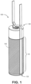
- Figure 1 illustrates a perspective view of a battery cell 100 including a graphene layer 140 applied thereto, according to an implementation.
- the cell 100 may be or include a lithium-ion (Li-ion) cell.
- the cell 100 may be or include a 18650 cell, a 21700 cell, a D cell, the like. However, in other implementations, the cell 100 may be or include other/different types, sizes, and/or shapes.
- the battery 100 is cylindrical and includes a cylindrical side wall 110, a first (e.g., upper) axial end wall 120, and a second (e.g., lower) axial end wall 130.
- the side wall 110 can have a (e.g., radial) thickness from about 100 micrometers ( ⁇ m) to about 200 ⁇ m, about 100 ⁇ m to about 150 ⁇ m, or about 100 ⁇ to about 125 ⁇ m.
- the first axial end wall 120 can be or may include the positive terminal, and the second end wall 130 can be or may include the negative terminal, or vice versa.
- the graphene layer 140 can be or may include a monocrystalline structure or a polycrystalline structure.
- the structure of the graphene layer 140 may depend at least partially upon the manner in which the graphene layer 140 is fabricated and/or applied, as discussed below.
- the monocrystalline structure may be more fracture-resistant than the polycrystalline structure.
- the polycrystalline structure may be less expensive than the monocrystalline structure to manufacture.
- the graphene layer 140 can be or may include a semimetal with a small overlap between the valence and conduction bands, which gives the graphene layer 140 a semiconductor structure that allows a user to control and/or modify the thermal and/or electrical properties, as discussed below.
- the graphene layer 140 can be or may include an allotrope of carbon including one or more layers of carbon atoms arranged in a (e.g., hexagonal) lattice.
- the allotrope of carbon in a single layer provides a strong but very think graphene layer 140. Additional layers increase the strength.
- the graphene layer 140 is positioned at least partially on and/or around an outer surface of the battery cell 100. According to the invention, the graphene layer 140 is positioned on the outer surface of the side wall 110. It may also be positioned on the first axial end wall 120, the second axial end wall 130, or a combination thereof. In the implementation shown, the graphene layer 140 is positioned on and/or around the side wall 110 (this expression meaning, in the whole description, that the graphene layer 140 is positioned on an outer surface of the side wall), but not the first and second axial end walls 120, 130. This can increase a strength of the side wall 110.
- the graphene layer 140 can reduce a likelihood that the side wall 110 will rupture, and direct/funnel the effects of the thermal runaway to the first and/or second axial end walls 120, 130, which may rupture to make way for the release of hot gases.
- the graphene layer 140 is positioned on and/or around the side wall 110 and the first axial end wall 120, but not the second end wall 130, such that, in the event that the battery cell 100 enters thermal runaway, the graphene layer 140 can reduce a likelihood that the side wall 110 and the first axial end wall 120 will rupture, and direct/funnel the effects of the thermal runaway to the second axial end wall 130, which may rupture to make way for the release of hot gases.
- the graphene layer 140 is positioned on and/or around the side wall 110 and the second axial end wall 130, but not the first axial end wall 120, such that, in the event that the battery cell 100 enters thermal runaway, the graphene layer 140 can reduce a likelihood that the side wall 110 and the second axial end wall 130 will rupture, and direct/funnel the effects of the thermal runaway to the first axial end wall 120, which may rupture to make way for the release of hot gases.
- the first axial end wall 120 and/or the second axial end wall 130 can include one or more vents to permit the release of at least a portion of the hot gases during lesser internal pressure events (e.g., caused by overheating during power delivery or charging as opposed to actually going into thermal runaway).
- the vents may not be sufficient, and one or both of the axial end walls 120, 130 may rupture.
- the graphene layer 140 can have a strength that is from about 689 bar (10,000 pounds per square inch (lbs/in 2 )) to about 34473 bar (500,000 lbs/in 2 ), about 1379 bar (20,000 lbs/in 2 ) to about 300,000 lbs/in 2 , or about 20684 bar (30,000 lbs/in 2 ) to about 6894 bar (100,000 lbs/in 2 ). Having a strength in the range(s) provided above may reduce the likelihood that graphene layer 140 (and/or the portion of the battery cell 100 covered by the graphene layer 140) will rupture during a thermal runaway event.
- the graphene layer 140 can be a single atom thick.
- the graphene layer 140 may have a (e.g., radial) thickness from about 0.4 ⁇ m to about 1.5 ⁇ m, about 0.6 ⁇ m (i.e., ⁇ 0.025 thousandths of an inch) to about 1.3 ⁇ m (i.e., ⁇ 0.050 thousandths of an inch), or about 0.8 ⁇ m to about 1.1 ⁇ m.
- a graphene layer 140 may be about 200 times stronger than a steel layer and about 200 times thinner than a steel layer. Due to how thin the graphene layer 140 may be, the cell 100 with the graphene layer 140 may remain within industry standards for size and thus may be integrated into existing interstitial materials without modification of the battery cell 100.
- the strength of the graphene layer 140 may be less effected by heat (e.g., at runaway temperatures) than conventional steel. For example, steel may lose as much as 90% of its strength at runaway temperatures.
- the graphene layer 140 can be a good thermal conductor.
- the graphene layer 140 may have a thermal conductivity from about 1000 watts per meter-kelvin (W/m*K) to about 2500 W/m*K or from about 1500 W/m*K to about 2000 W/m*K. A thermal conductivity in this range allows the graphene layer 140 to help dissipate/bleed off the heat load during thermal runaway.
- the graphene layer 140 may be doped to alter the characteristics of its thermal behavior.
- a plurality of doped graphene layers may be present. This doping can reduce the thermal conductivity from a baseline value. More particularly, this doping can minimize the thermal gradient across a core with multiple battery cells such that the electrical behavior and/or cell life remains substantially constant. In addition, this may reduce the effectiveness of a battery passive thermal control system such that the system may warm faster and/or operate ate more moderate temperatures in a cold environment.
- the graphene layer 140 can also be a good electrical conductor.
- the graphene layer 140 may have an electrical resistivity from about 0.5E-6 ohms per meter ( ⁇ /m) to about 10E-6 ⁇ /m or from about 1E-6 ⁇ /m to about 5E-6 ⁇ /m.
- An electrical conductivity in this range allows the battery cell 100 and/or the graphene layer 140 to be more easily integrated into a core circuit.
- the graphene layer 140 can be coupled to and/or in contact with the positive terminal and/or the negative terminal of the battery cell 100 and have electrical current conducted therethrough (see, e.g., Figure 2 ).
- the graphene layer 140 may be doped to alter the characteristics of its electrical behavior.
- a plurality of doped graphene layers may be present. This doping may allow for switching the negative (can) terminal of the battery cell 100 into or out of the battery electrical architecture in a matter similar to a semiconductor. More particularly, this may allow for switching the battery cell 100 into or out of the matrix of a variety of scenarios (e.g., cell fault, core capacity balancing, change of S-P architecture, etc.).
- the graphene layer 140 may be applied to the (e.g., side wall 110 of the) battery cell 100 in a variety of ways.
- the graphene layer 140 can be applied by wrapping a sheet of the graphene layer 140 around at least a portion (e.g., the side wall 110) of the battery cell 100. This may include wrapping a plurality of sheets of the graphene layer 140 sequentially. When the sheet(s) is/are wrapped, the graphene may have a monocrystalline structure, which as described above, may be more fracture-resistant than a polycrystalline structure.
- the graphene layer 140 can be applied by growing the graphene in place. This may include chemical vapor deposition and/or physical vapor deposition; however, other methods may also be used to grow the graphene in place. When the graphene is grown, the graphene may have a polycrystalline structure, which as described above, can be less expensive to manufacture than a monocrystalline structure.
- the graphene layer 140 can be formed into a (e.g., cylindrical) sleeve, which may be positioned/slid at least partially around and/or over the battery cell 100. This can provide for easy installation.
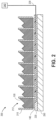
- FIG. 2 illustrates a schematic view of a system 200 for controlling a thermal conductivity of the graphene layer(s) 140, according to an implementation.
- the system 200 includes a cell support structure 210 defining a plurality of openings 212 in which the battery cell(s) 100 may be positioned. As shown, at least a portion of the side wall 110 of each battery cell 100 may be in contact with the cell support structure 210. In this manner, the cell support structure 210 can support the battery cell(s) in the desired location and orientation.
- the graphene layer 140 is positioned at an outer surface of the side wall 110 and it is further positioned on either the first axial end wall 120 or the second axial end wall 130.
- the graphene layer 140 can be or may include a doped graphene thermal interface, which may include one or more layers. As shown, the graphene layer 140 may be in contact with the second (e.g., lower) axial end wall 130 of each battery cell 100. However, as will be appreciated, in other implementations, the graphene layer 140 is also or instead be in contact with the side wall 110. The graphene layer may also be in contact with the first (e.g., upper) axial end wall 120.
- the system 200 also includes a thermal pad 220 that provides insulation.
- the thermal pad 220 is positioned below/beneath the battery cells 100, the graphene layer(s) 140, and/or the cell support structure 210. As shown, the graphene layer(s) 140 may be positioned between the battery cells 100 and the thermal pad 220.
- the thermal pad 220 may have a conduit formed at least partially therethrough in which a wire 230 may be positioned.
- the wire 230 extends from an electrical control interface 240 to the graphene layer(s) 140.
- the electrical control interface 240 modifies one or more characteristics (e.g., thermal conductivity) of the graphene layer(s) 140 by modifying the voltage and/or current supplied thereto via the wire 230.
- the thermal conductivity can be adjusted from a minimum value to a maximum value, which may be within the range(s) provided above.
- the graphene layer(s) 140 may default to the maximum value for heat conduction.
- supplying voltage and/or current to the graphene layer(s) 140 can cause the thermal conductivity (e.g., heat conduction) to decrease.
- the ability to vary the thermal conductivity may enable a user to control the graphene layer 140 to help dissipate/bleed off the heat load during thermal runaway.
- the system 200 also includes an enclosure bottom 250.
- the enclosure bottom 250 is positioned below/beneath the battery cells 100, the graphene layer(s) 140, the cell support structure 210, and the thermal pad 220. As shown, the thermal pad 220 may be positioned between the graphene layer(s) 140 and the enclosure bottom 250.
- the enclosure bottom 250 serves as a heat sink.
- Figure 3 illustrates a schematic view of a system 300 for controlling an electrical conductivity/resistivity of the graphene layer(s) 140, which is not encompassed by the wording of the claims but considered as useful for understanding the present teachings.
- the system 300 may be similar to the system 200.
- the system 300 also includes a cell support structure 310 that at least partially defines a plurality of recesses or openings 312 in which the battery cell(s) 100 may be positioned.
- the side wall 110 and/or the second (e.g., lower) end wall 130 of each battery cell 100 may be in contact with the cell support structure 310.
- the cell support structure 310 provides electrical isolation and/or a thermal interface for the battery cells 100.
- the system 300 can include one or more bus ties 320 that may at least partially define the openings 312 in which the battery cell(s) 100 are positioned. As shown, at least a portion of the side wall 110 of each battery cell 100 may be aligned with the bus tie(s) 320.
- the bus tie(s) 320 may transmit power from the battery cell(s) 100 to a load.
- the system 300 also includes the graphene layer 140.
- the graphene layer 140 can be or may include a doped graphene electrical interface, which can include one or more layers. As shown, the graphene layer 140 is in contact with the side wall 110 of each battery cell 100, the cell support structure 310, and the bus tie(s) 320. However, as will be appreciated, in other implementations, the graphene layer 140 may also be in contact with the first (e.g., upper) end wall 120, the second (e.g., lower) end wall 130, or both.
- the system 300 also includes a wire 330 and an electrical control interface 340.
- the electrical control interface 340 modifies one or more characteristics (e.g., electrical conductivity and/or resistivity) of the graphene layer(s) 140 by modifying the voltage and/or current supplied thereto via the wire 330.
- the thermal conductivity and/or resistivity may be adjusted from a minimum value to a maximum value, which may be within the range(s) provided above.
- the graphene layer(s) 140 may default to isolating the circuit to its maximum potential as a safety mechanism.
- this may be changed to the alternative state so that it instead defaults to maximum electrical conduction.
- This may be selectively applied in different areas of the battery core by using different doping constructs in different locations.
- the ability to vary the electrical conductivity may enable a user to control the graphene layer 140 to help the battery cell 100 and/or the graphene layer 140 to be more easily integrated into the core circuit.
- the system 300 also includes an enclosure bottom 350.
- the enclosure bottom 350 is positioned below/beneath the battery cells 100 and the cell support structure 310.
- the cell support structure 310 may be positioned between the battery cells 100 and the enclosure bottom 350.
- Figure 4 illustrates a schematic view of a circuit 400 for controlling the graphene layer 140, according to an implementation.
- the circuit 400 can be or may include a doped graphene interface that is modelled as transistors 410.
- the transistors 410 may be or include field effect transistors (FETs).
- FETs field effect transistors
- the circuit 400 may also include a first (e.g., positive) bus 420 and a second (e.g., negative) bus 430.
- a controller 440 may be used to control the graphene layer by supplying and/or varying the electrical current and/or voltage supplied thereto. Control of the graphene layer can determine if the battery cell is in-circuit or out-of-circuit (or therebetween of an analog function is desired). The control of the graphene layer permits isolating a battery cell from the power buses 420, 430 if required for electrical performance or safety reasons. The control of thermal properties may be substantially the same as the control of electrical properties.
- FIG. 5 illustrates a schematic view of a functional block diagram 500, according to an implementation.
- the functional block diagram 500 includes components from Figure 1 , Figure 2 , and/or Figure 3 .
- the functional block diagram 500 includes the battery cell 100 and the graphene layer 140 from Figure 1 .
- the functional block diagram 500 includes the battery cell 110, the graphene layer 140, the cell support structure 210, the thermal pad 220, the wire 230, the electrical control interface 240, and the enclosure bottom 250 from Figure 2 .
- the functional block diagram 500 includes the battery cell 100, the graphene layer 140, the cell support structure 310, the bus tie 320, the wire 330, the electrical control interface 340, and the enclosure bottom 350 from Figure 3 , that illustrates an embodiment not according to the invention.
- the functional block diagram 500 illustrates one example of the connections and interactions of the components, a more detailed description of which is provided above.
Landscapes
- Chemical & Material Sciences (AREA)
- Chemical Kinetics & Catalysis (AREA)
- Electrochemistry (AREA)
- General Chemical & Material Sciences (AREA)
- Engineering & Computer Science (AREA)
- Manufacturing & Machinery (AREA)
- Inorganic Chemistry (AREA)
- Secondary Cells (AREA)
- Carbon And Carbon Compounds (AREA)
- Battery Electrode And Active Subsutance (AREA)
Description
- The present disclosure is directed to systems and methods for improving battery cells. More particularly, the present disclosure is directed to systems and methods for improving lithium-ion battery cells during thermal runaway.
- Modern battery assemblies can include one or more (e.g., hundreds of) cells that use a common form factor size, such as cylindrical, pouch, or prismatic. The cells may be or include lithium-ion (Li-ion) cells. Li-ion cells may have a (e.g., cylindrical) side wall that is only about 127 µm (0.005 inches) thick to maximize the interior volume, thereby promoting higher energy capacity.
- Li-ion cells are sensitive to high temperatures. At temperatures above, for example, about 90°C, the cells may progress into thermal runaway. Thermal runaway occurs in situations where an increase in temperature changes the conditions in a way that causes a further increase in temperature. It is a type of uncontrolled positive feedback. During thermal runaway, cell temperatures can reach or exceed about 800°C, and cell vent gas temperatures can reach or exceed about 1000°C.
- During a thermal runaway event, the thin side wall of the battery cell may rupture, which may direct energy towards an adjacent battery cell, causing it to also enter thermal runaway. Thus, the problem may propagate to a plurality of battery cells.
-
CN 207572408 U , in accordance with its English abstract, provides a cylindrical electrochemical device provided with graphite alkene coating in connection zone. This utility model provides the electrochemical device with anti striking, anti puncture ability. -
US 2018/0090731 A1 discloses a thermal runaway shield ("TRS") having at least one TRS module. The TRS module comprises a first wall, a second wall, and fibers. The first wall has an exterior side and an interior side. The second wall has an exterior side and an interior side. The fibers are disposed on the interior side of the first wall and on the interior side of the second wall. The first wall is coupled to the second wall forming an inner cavity. The at least one of the exterior side of the first wall and the exterior side of the second wall has a shape for conforming to a shape of at least one energy storage device cell. - The paper from ALEXANDER A. BALANDIN: "Thermal properties of graphene and nanostructured carbon materials", NATURE MATERIALS, vol. 10, no. 8, 22 July 2011 (2011-07-22), pages 569-581, XP055696357, London ISSN: 1476-1122, DOI: 10.1038/nmat3064 discloses that recent years have seen a rapid growth of interest by the scientific and engineering communities in the thermal properties of materials. Heat removal has become a crucial issue for continuing progress in the electronic industry, and thermal conduction in low-dimensional structures has revealed truly intriguing features. Carbon allotropes and their derivatives occupy a unique place in terms of their ability to conduct heat. The room-temperature thermal conductivity of carbon materials span an extra-ordinary large range - of over five orders of magnitude - from the lowest in amorphous carbons to the highest in graphene and carbon nanotubes. The document further reviews the thermal properties of carbon materials focusing on recent results for graphene, carbon nanotubes and nanostructured carbon materials with different degrees of disorder. Special attention is given to the unusual size dependence of heat conduction in two-dimensional crystals and, specifically, in graphene and to the prospects of applications of graphene and carbon materials for thermal management of electronics.
-
US 2015/0118537 discloses a thermal assembly for a battery cell that includes a battery cell having a battery cell packaging and a thermal pouch formed from a continuous carbon-based thermal film. The thermal pouch is configured to contact both the battery cell packaging and one or more thermal management features of a battery module with a first side of the carbon-based thermal film. Accordingly, the first side of the carbon-based thermal film is configured to provide uninterrupted thermal pathways along the first side of the carbon-based thermal film between the battery cell packaging and the one or more thermal management features of the battery module. - A system is defined in claim 1.
- A method is defined in claim 11.
- It is to be understood that both the foregoing general description and the following detailed description are exemplary and explanatory only and are not restrictive of the present teachings, as claimed.
- The accompanying drawings, which are incorporated in and constitute a part of this specification, illustrate aspects of the present teachings and together with the description, serve to explain the principles of the present teachings.
-
Figure 1 illustrates a perspective view of a battery cell including a graphene layer applied thereto, according to an implementation. -
Figure 2 illustrates a schematic view of a system for controlling a thermal conductivity of the graphene layer, according to an implementation. -
Figure 3 illustrates a schematic view of a system for controlling an electrical conductivity/resistivity of the graphene layer, according to an example not encompassed by the wording of the claims but considered as useful for understanding the present teachings. -
Figure 4 illustrates a schematic view of a circuit for controlling the graphene layer, according to an implementation. -
Figure 5 illustrates a schematic view of a functional block diagram, according to an implementation. - It should be noted that some details of the figures have been simplified and are drawn to facilitate understanding rather than to maintain strict structural accuracy, detail, and scale.
- Reference will now be made in detail to the present teachings, examples of which are illustrated in the accompanying drawings. In the drawings, like reference numerals have been used throughout to designate identical elements. In the following description, reference is made to the accompanying drawings that form a part thereof, and in which is shown by way of illustration specific examples of practicing the present teachings. The following description is, therefore, merely exemplary.
- The system and method disclosed herein is configured to prevent propagation of a thermal runaway event from one battery cell to one or more neighboring battery cells. More particularly, the system and method may ensure that, if any single cell has a failure and enters thermal runaway, the effects of the thermal runaway (e.g., rupturing of the cell) is directed toward/through one or both axial ends of the cell, instead of through the cylindrical side wall of the cell. This may prevent propagation of a thermal runaway event from the battery cell to neighboring battery cell(s) that is/are positioned next to (i.e., side-by-side with) the battery cell.
-
Figure 1 illustrates a perspective view of abattery cell 100 including agraphene layer 140 applied thereto, according to an implementation. Thecell 100 may be or include a lithium-ion (Li-ion) cell. Thecell 100 may be or include a 18650 cell, a 21700 cell, a D cell, the like. However, in other implementations, thecell 100 may be or include other/different types, sizes, and/or shapes. - As shown in
Figure 1 , thebattery 100 is cylindrical and includes acylindrical side wall 110, a first (e.g., upper)axial end wall 120, and a second (e.g., lower)axial end wall 130. Theside wall 110 can have a (e.g., radial) thickness from about 100 micrometers (µm) to about 200µm, about 100 µm to about 150 µm, or about 100 µ to about 125 µm. The firstaxial end wall 120 can be or may include the positive terminal, and thesecond end wall 130 can be or may include the negative terminal, or vice versa. - The
graphene layer 140 can be or may include a monocrystalline structure or a polycrystalline structure. The structure of thegraphene layer 140 may depend at least partially upon the manner in which thegraphene layer 140 is fabricated and/or applied, as discussed below. The monocrystalline structure may be more fracture-resistant than the polycrystalline structure. The polycrystalline structure may be less expensive than the monocrystalline structure to manufacture. Thegraphene layer 140 can be or may include a semimetal with a small overlap between the valence and conduction bands, which gives the graphene layer 140 a semiconductor structure that allows a user to control and/or modify the thermal and/or electrical properties, as discussed below. Thegraphene layer 140 can be or may include an allotrope of carbon including one or more layers of carbon atoms arranged in a (e.g., hexagonal) lattice. The allotrope of carbon in a single layer provides a strong but very thinkgraphene layer 140. Additional layers increase the strength. - The
graphene layer 140 is positioned at least partially on and/or around an outer surface of thebattery cell 100. According to the invention, thegraphene layer 140 is positioned on the outer surface of theside wall 110. It may also be positioned on the firstaxial end wall 120, the secondaxial end wall 130, or a combination thereof. In the implementation shown, thegraphene layer 140 is positioned on and/or around the side wall 110 (this expression meaning, in the whole description, that thegraphene layer 140 is positioned on an outer surface of the side wall), but not the first and secondaxial end walls side wall 110. Accordingly, in the event that thebattery cell 100 enters thermal runaway, thegraphene layer 140 can reduce a likelihood that theside wall 110 will rupture, and direct/funnel the effects of the thermal runaway to the first and/or secondaxial end walls - In another implementation, the
graphene layer 140 is positioned on and/or around theside wall 110 and the firstaxial end wall 120, but not thesecond end wall 130, such that, in the event that thebattery cell 100 enters thermal runaway, thegraphene layer 140 can reduce a likelihood that theside wall 110 and the firstaxial end wall 120 will rupture, and direct/funnel the effects of the thermal runaway to the secondaxial end wall 130, which may rupture to make way for the release of hot gases. In yet another implementation, thegraphene layer 140 is positioned on and/or around theside wall 110 and the secondaxial end wall 130, but not the firstaxial end wall 120, such that, in the event that thebattery cell 100 enters thermal runaway, thegraphene layer 140 can reduce a likelihood that theside wall 110 and the secondaxial end wall 130 will rupture, and direct/funnel the effects of the thermal runaway to the firstaxial end wall 120, which may rupture to make way for the release of hot gases. - In at least one implementation, the first
axial end wall 120 and/or the secondaxial end wall 130 can include one or more vents to permit the release of at least a portion of the hot gases during lesser internal pressure events (e.g., caused by overheating during power delivery or charging as opposed to actually going into thermal runaway). However, in the event that thebattery cell 100 enters thermal runaway, the vents may not be sufficient, and one or both of theaxial end walls - The
graphene layer 140 can have a strength that is from about 689 bar (10,000 pounds per square inch (lbs/in2)) to about 34473 bar (500,000 lbs/in2), about 1379 bar (20,000 lbs/in2) to about 300,000 lbs/in2, or about 20684 bar (30,000 lbs/in2 ) to about 6894 bar (100,000 lbs/in2). Having a strength in the range(s) provided above may reduce the likelihood that graphene layer 140 (and/or the portion of thebattery cell 100 covered by the graphene layer 140) will rupture during a thermal runaway event. In at least one implementation, thegraphene layer 140 can be a single atom thick. In other implementations, thegraphene layer 140 may have a (e.g., radial) thickness from about 0.4 µm to about 1.5 µm, about 0.6 µm (i.e., ~0.025 thousandths of an inch) to about 1.3 µm (i.e., ~0.050 thousandths of an inch), or about 0.8 µm to about 1.1 µm. Such agraphene layer 140 may be about 200 times stronger than a steel layer and about 200 times thinner than a steel layer. Due to how thin thegraphene layer 140 may be, thecell 100 with thegraphene layer 140 may remain within industry standards for size and thus may be integrated into existing interstitial materials without modification of thebattery cell 100. In addition, the strength of thegraphene layer 140 may be less effected by heat (e.g., at runaway temperatures) than conventional steel. For example, steel may lose as much as 90% of its strength at runaway temperatures. - The
graphene layer 140 can be a good thermal conductor. For example, thegraphene layer 140 may have a thermal conductivity from about 1000 watts per meter-kelvin (W/m*K) to about 2500 W/m*K or from about 1500 W/m*K to about 2000 W/m*K. A thermal conductivity in this range allows thegraphene layer 140 to help dissipate/bleed off the heat load during thermal runaway. - The
graphene layer 140 may be doped to alter the characteristics of its thermal behavior. In one implementation, a plurality of doped graphene layers may be present. This doping can reduce the thermal conductivity from a baseline value. More particularly, this doping can minimize the thermal gradient across a core with multiple battery cells such that the electrical behavior and/or cell life remains substantially constant. In addition, this may reduce the effectiveness of a battery passive thermal control system such that the system may warm faster and/or operate ate more moderate temperatures in a cold environment. - The
graphene layer 140 can also be a good electrical conductor. For example, thegraphene layer 140 may have an electrical resistivity from about 0.5E-6 ohms per meter (Ω/m) to about 10E-6 Ω/m or from about 1E-6 Ω/m to about 5E-6 Ω/m. An electrical conductivity in this range allows thebattery cell 100 and/or thegraphene layer 140 to be more easily integrated into a core circuit. For example, thegraphene layer 140 can be coupled to and/or in contact with the positive terminal and/or the negative terminal of thebattery cell 100 and have electrical current conducted therethrough (see, e.g.,Figure 2 ). - The
graphene layer 140 may be doped to alter the characteristics of its electrical behavior. In one implementation, a plurality of doped graphene layers may be present. This doping may allow for switching the negative (can) terminal of thebattery cell 100 into or out of the battery electrical architecture in a matter similar to a semiconductor. More particularly, this may allow for switching thebattery cell 100 into or out of the matrix of a variety of scenarios (e.g., cell fault, core capacity balancing, change of S-P architecture, etc.). - The
graphene layer 140 may be applied to the (e.g.,side wall 110 of the)battery cell 100 in a variety of ways. In one implementation, thegraphene layer 140 can be applied by wrapping a sheet of thegraphene layer 140 around at least a portion (e.g., the side wall 110) of thebattery cell 100. This may include wrapping a plurality of sheets of thegraphene layer 140 sequentially. When the sheet(s) is/are wrapped, the graphene may have a monocrystalline structure, which as described above, may be more fracture-resistant than a polycrystalline structure. - In another implementation, the
graphene layer 140 can be applied by growing the graphene in place. This may include chemical vapor deposition and/or physical vapor deposition; however, other methods may also be used to grow the graphene in place. When the graphene is grown, the graphene may have a polycrystalline structure, which as described above, can be less expensive to manufacture than a monocrystalline structure. - In yet another implementation, the
graphene layer 140 can be formed into a (e.g., cylindrical) sleeve, which may be positioned/slid at least partially around and/or over thebattery cell 100. This can provide for easy installation. -
Figure 2 illustrates a schematic view of asystem 200 for controlling a thermal conductivity of the graphene layer(s) 140, according to an implementation. Thesystem 200 includes acell support structure 210 defining a plurality ofopenings 212 in which the battery cell(s) 100 may be positioned. As shown, at least a portion of theside wall 110 of eachbattery cell 100 may be in contact with thecell support structure 210. In this manner, thecell support structure 210 can support the battery cell(s) in the desired location and orientation. - The
graphene layer 140 is positioned at an outer surface of theside wall 110 and it is further positioned on either the firstaxial end wall 120 or the secondaxial end wall 130. In this implementation, thegraphene layer 140 can be or may include a doped graphene thermal interface, which may include one or more layers. As shown, thegraphene layer 140 may be in contact with the second (e.g., lower)axial end wall 130 of eachbattery cell 100. However, as will be appreciated, in other implementations, thegraphene layer 140 is also or instead be in contact with theside wall 110. The graphene layer may also be in contact with the first (e.g., upper)axial end wall 120. - The
system 200 also includes athermal pad 220 that provides insulation. Thethermal pad 220 is positioned below/beneath thebattery cells 100, the graphene layer(s) 140, and/or thecell support structure 210. As shown, the graphene layer(s) 140 may be positioned between thebattery cells 100 and thethermal pad 220. Thethermal pad 220 may have a conduit formed at least partially therethrough in which awire 230 may be positioned. Thewire 230 extends from anelectrical control interface 240 to the graphene layer(s) 140. The electrical control interface 240 (e.g., electrically) modifies one or more characteristics (e.g., thermal conductivity) of the graphene layer(s) 140 by modifying the voltage and/or current supplied thereto via thewire 230. For example, the thermal conductivity can be adjusted from a minimum value to a maximum value, which may be within the range(s) provided above. When not controlled by theelectrical control interface 240 and the wire 230 (i.e., when no voltage or current is supplied), the graphene layer(s) 140 may default to the maximum value for heat conduction. Thus, supplying voltage and/or current to the graphene layer(s) 140 can cause the thermal conductivity (e.g., heat conduction) to decrease. As mentioned above, the ability to vary the thermal conductivity may enable a user to control thegraphene layer 140 to help dissipate/bleed off the heat load during thermal runaway. - The
system 200 also includes anenclosure bottom 250. Theenclosure bottom 250 is positioned below/beneath thebattery cells 100, the graphene layer(s) 140, thecell support structure 210, and thethermal pad 220. As shown, thethermal pad 220 may be positioned between the graphene layer(s) 140 and theenclosure bottom 250. Theenclosure bottom 250 serves as a heat sink. -
Figure 3 illustrates a schematic view of asystem 300 for controlling an electrical conductivity/resistivity of the graphene layer(s) 140, which is not encompassed by the wording of the claims but considered as useful for understanding the present teachings. Thesystem 300 may be similar to thesystem 200. For example, thesystem 300 also includes acell support structure 310 that at least partially defines a plurality of recesses oropenings 312 in which the battery cell(s) 100 may be positioned. As shown, at least a portion of theside wall 110 and/or the second (e.g., lower)end wall 130 of eachbattery cell 100 may be in contact with thecell support structure 310. Thecell support structure 310 provides electrical isolation and/or a thermal interface for thebattery cells 100. - The
system 300 can include one ormore bus ties 320 that may at least partially define theopenings 312 in which the battery cell(s) 100 are positioned. As shown, at least a portion of theside wall 110 of eachbattery cell 100 may be aligned with the bus tie(s) 320. The bus tie(s) 320 may transmit power from the battery cell(s) 100 to a load. - The
system 300 also includes thegraphene layer 140. In this implementation, thegraphene layer 140 can be or may include a doped graphene electrical interface, which can include one or more layers. As shown, thegraphene layer 140 is in contact with theside wall 110 of eachbattery cell 100, thecell support structure 310, and the bus tie(s) 320. However, as will be appreciated, in other implementations, thegraphene layer 140 may also be in contact with the first (e.g., upper)end wall 120, the second (e.g., lower)end wall 130, or both. - The
system 300 also includes awire 330 and anelectrical control interface 340. The electrical control interface 340 (e.g., electrically) modifies one or more characteristics (e.g., electrical conductivity and/or resistivity) of the graphene layer(s) 140 by modifying the voltage and/or current supplied thereto via thewire 330. For example, the thermal conductivity and/or resistivity may be adjusted from a minimum value to a maximum value, which may be within the range(s) provided above. When not controlled by theelectrical control interface 340 and the wire 330 (i.e., when no voltage or current is supplied), the graphene layer(s) 140 may default to isolating the circuit to its maximum potential as a safety mechanism. In another implementation, this may be changed to the alternative state so that it instead defaults to maximum electrical conduction. This may be selectively applied in different areas of the battery core by using different doping constructs in different locations. As mentioned above, the ability to vary the electrical conductivity may enable a user to control thegraphene layer 140 to help thebattery cell 100 and/or thegraphene layer 140 to be more easily integrated into the core circuit. - The
system 300 also includes anenclosure bottom 350. Theenclosure bottom 350 is positioned below/beneath thebattery cells 100 and thecell support structure 310. As shown, thecell support structure 310 may be positioned between thebattery cells 100 and theenclosure bottom 350. -
Figure 4 illustrates a schematic view of acircuit 400 for controlling thegraphene layer 140, according to an implementation. Thecircuit 400 can be or may include a doped graphene interface that is modelled astransistors 410. Thetransistors 410 may be or include field effect transistors (FETs). Thecircuit 400 may also include a first (e.g., positive) bus 420 and a second (e.g., negative) bus 430. - A
controller 440 may be used to control the graphene layer by supplying and/or varying the electrical current and/or voltage supplied thereto. Control of the graphene layer can determine if the battery cell is in-circuit or out-of-circuit (or therebetween of an analog function is desired). The control of the graphene layer permits isolating a battery cell from the power buses 420, 430 if required for electrical performance or safety reasons. The control of thermal properties may be substantially the same as the control of electrical properties. -
Figure 5 illustrates a schematic view of a functional block diagram 500, according to an implementation. The functional block diagram 500 includes components fromFigure 1 ,Figure 2 , and/orFigure 3 . For example, the functional block diagram 500 includes thebattery cell 100 and thegraphene layer 140 fromFigure 1 . The functional block diagram 500 includes thebattery cell 110, thegraphene layer 140, thecell support structure 210, thethermal pad 220, thewire 230, theelectrical control interface 240, and theenclosure bottom 250 fromFigure 2 . The functional block diagram 500 includes thebattery cell 100, thegraphene layer 140, thecell support structure 310, thebus tie 320, thewire 330, theelectrical control interface 340, and theenclosure bottom 350 fromFigure 3 , that illustrates an embodiment not according to the invention. The functional block diagram 500 illustrates one example of the connections and interactions of the components, a more detailed description of which is provided above. - Notwithstanding that the numerical ranges and parameters setting forth the broad scope of the disclosure are approximations, the numerical values set forth in the specific examples are reported as precisely as possible. Any numerical value, however, inherently contains certain errors necessarily resulting from the standard deviation found in their respective testing measurements. Moreover, all ranges disclosed herein are to be understood to encompass any and all sub-ranges subsumed therein.
Claims (15)
- A system, comprising:a cylindrical battery cell (100) comprising a side wall (110), a first axial end wall (120), and a second axial end wall (130);a graphene layer (140) positioned on an outer surface of the side wall (110) of the battery cell (100);an electrical control interface (240, 340) configured to supply power to the graphene layer to modify a thermal conductivity of the graphene layer, an electrical resistivity of the graphene layer, or both;a wire (230; 330) configured to transmit the power from the electrical control interface (240, 340) to the graphene layer (140);a cell support (210, 310) defining an opening (212, 312) in which the battery cell is positioned;a thermal pad (220) positioned below the battery cell (100), the graphene layer (140) and/or the cell support structure (210); andan enclosure bottom (250; 350) serving as a heat sink and positioned below the battery cell (100).
- The system of claim 1, wherein the graphene layer (140) is positioned on an outer surface of the side wall (110), and wherein the graphene layer is further positioned on either the first axial end wall (120) or the second axial end wall (130).
- The system of any of claims 1-2, wherein the graphene layer (140) has a thickness from about 0.4 micrometers (µm) to about 1.5 µm.
- The system of any of claims 1-3, wherein the graphene layer (140) has a strength from about 689 Bar (10,000 pounds per square inch (lbs/in2)) to about 34473 Bar (500,000 lbs/in2).
- The system of any of claims 1-4, wherein the graphene layer (140) has a thermal conductivity from about 1000 watts per meter-kelvin (W/m*K) to about 2500 W/m*K.
- The system of any of claims 1-5, wherein the graphene layer (140) has an electrical resistivity from about 0.5E-6 ohms per meter (Ω/m) to about 10E-6 Ω/m.
- The system of any of claims 1 to 6, wherein the graphene layer (140) comprises a monocrystalline structure.
- The system of any of claims 1 to 6, wherein the graphene layer (140) comprises a polycrystalline structure.
- The system of claim 2,wherein the graphene layer (140) is positioned between the second axial end wall (120, 130) of the battery cell (100) and the thermal pad (220);wherein the thermal pad (220) is positioned between the further graphene layer (140) and the enclosure bottom (250); andwherein the wire (230) is positioned at least partially in a conduit in the thermal pad (220).
- The system of claim 6, wherein the graphene layer is doped to alter the electrical resisitivity.
- A method, comprising:providing a cylindrical battery cell (100) comprising a side wall (110), a first axial end wall (120) and a second axial end wall (130);applying a graphene layer (140) on an outer surface of the side wall (110) of the battery (110) cell to increase a strength of the side wall, thereby reducing a likelihood that the side wall will rupture during a thermal runaway event,providing an electrical control interface (240, 340) configured to supply power to the graphene layer to modify a thermal conductivity of the graphene layer, an electrical resistivity of the graphene layer, or both;providing a wire (230; 330) configured to transmit the power from the electrical control interface (240, 340) to the graphene layer (140);providing a cell support (210, 310) defining an opening (212, 312) in which the battery cell is positioned;providing a thermal pad (220; 310) below the battery cell (100), the graphene layer (140) and/or the cell support structure (210); andproviding an enclosure bottom (250; 350) serving as a heat sink and positioned below the battery cell (100).
- The method of claim 11, wherein applying the graphene layer (140) comprises wrapping a sheet of the graphene layer around the side wall, and wherein the graphene layer comprises a monocrystalline structure.
- The method of claim 11, wherein applying the graphene layer (140) comprises growing the graphene layer in place, and wherein the graphene layer comprises a polycrystalline structure, wherein growing the graphene layer (140) in place is performed by chemical vapor deposition or physical vapor deposition.
- The method of any of claims 11-13, wherein applying the graphene layer (140) comprises:forming the graphene layer into a sleeve; andsliding the sleeve at least partially around the battery cell.
- The method of claim 11, wherein the graphene layer (140) has a thickness from about 0.4 micrometers (µm) to about 1.5 µm.
Applications Claiming Priority (1)
| Application Number | Priority Date | Filing Date | Title |
|---|---|---|---|
| US16/242,802 US10938077B2 (en) | 2019-01-08 | 2019-01-08 | System and method for improving a battery cell |
Publications (2)
| Publication Number | Publication Date |
|---|---|
| EP3680951A1 EP3680951A1 (en) | 2020-07-15 |
| EP3680951B1 true EP3680951B1 (en) | 2024-07-24 |
Family
ID=68732817
Family Applications (1)
| Application Number | Title | Priority Date | Filing Date |
|---|---|---|---|
| EP19212380.0A Active EP3680951B1 (en) | 2019-01-08 | 2019-11-29 | System and method for improving a battery cell |
Country Status (2)
| Country | Link |
|---|---|
| US (1) | US10938077B2 (en) |
| EP (1) | EP3680951B1 (en) |
Families Citing this family (4)
| Publication number | Priority date | Publication date | Assignee | Title |
|---|---|---|---|---|
| US11329329B2 (en) * | 2019-01-09 | 2022-05-10 | Chongqing Jinkang Powertrain New Energy Co., Ltd. | Systems and methods for cooling battery cells |
| USD1079601S1 (en) * | 2022-07-18 | 2025-06-17 | Xiamen Hithium Energy Storage Technology Co., Ltd. | Cylindrical battery |
| USD1079600S1 (en) * | 2022-08-29 | 2025-06-17 | Xiamen Hithium Energy Storage Technology Co., Ltd. | Cylindrical battery |
| US12555994B2 (en) * | 2022-10-07 | 2026-02-17 | Archer Aviation Inc. | Systems and methods for improved battery assemblies for eVTOL aircraft |
Citations (1)
| Publication number | Priority date | Publication date | Assignee | Title |
|---|---|---|---|---|
| US20150118537A1 (en) * | 2013-10-28 | 2015-04-30 | Johnson Controls Technology Company | System and method for battery cell thermal management using carbon-based thermal films |
Family Cites Families (3)
| Publication number | Priority date | Publication date | Assignee | Title |
|---|---|---|---|---|
| US9196939B2 (en) * | 2011-11-02 | 2015-11-24 | GM Global Technology Operations LLC | Method for thermal management and mitigation of thermal propagation for batteries using a graphene coated polymer barrier substrate |
| US10727462B2 (en) | 2016-09-28 | 2020-07-28 | KULR Technology Corporation | Thermal runaway shield |
| CN207572408U (en) | 2017-12-13 | 2018-07-03 | 宁德新能源科技有限公司 | Electrochemical appliance housing and electrochemical appliance |
-
2019
- 2019-01-08 US US16/242,802 patent/US10938077B2/en active Active
- 2019-11-29 EP EP19212380.0A patent/EP3680951B1/en active Active
Patent Citations (1)
| Publication number | Priority date | Publication date | Assignee | Title |
|---|---|---|---|---|
| US20150118537A1 (en) * | 2013-10-28 | 2015-04-30 | Johnson Controls Technology Company | System and method for battery cell thermal management using carbon-based thermal films |
Also Published As
| Publication number | Publication date |
|---|---|
| EP3680951A1 (en) | 2020-07-15 |
| US10938077B2 (en) | 2021-03-02 |
| US20200220121A1 (en) | 2020-07-09 |
Similar Documents
| Publication | Publication Date | Title |
|---|---|---|
| EP3680951B1 (en) | System and method for improving a battery cell | |
| JP6661770B2 (en) | Battery passive thermal management system | |
| EP2759019B1 (en) | Preventing cell thermal runaway propagation within a battery | |
| Guo et al. | Three-dimensional thermal finite element modeling of lithium-ion battery in thermal abuse application | |
| EP3176851B1 (en) | Electrical energy storage device | |
| CN110114903B (en) | Partition member, battery pack, and heat transfer control method for battery pack | |
| EP2933872A1 (en) | Tri-layer material for heat spreading in battery pack modules | |
| JP7687962B2 (en) | Temperature control system for lithium-ion battery cells | |
| JP6070672B2 (en) | Power storage module | |
| US10193196B1 (en) | Internal battery cell cooling with heat pipe | |
| US6797427B2 (en) | System for enhanced lithium-ion battery performance at low temperatures | |
| CN104347914B (en) | The battery module that the temperature change of battery cell is optimised is constructed | |
| JP6954213B2 (en) | Control method of filling member, assembled battery and heat transfer | |
| Mukane et al. | Performance and analysis of battery thermal management system used in electric vehicles (EVS) | |
| CN112083035A (en) | Test device and test method for thermal conductivity of lithium ion battery | |
| EP2948994B1 (en) | Method for producing an energy accumulator | |
| US20220238936A1 (en) | Battery thermal management strip | |
| KR102506814B1 (en) | Battery heater module for cold start and battery system comprising the same | |
| CN104412436A (en) | Controlling temperature in a fuel cell system | |
| US20260081251A1 (en) | Thermal management device, battery module, and electric equipment | |
| CN221176357U (en) | Automobile battery pack heat dissipation system and automobile | |
| ZHANG et al. | Effect of battery arrangement on the phase change thermal management performance of lithium-ion battery packs | |
| CN218215442U (en) | Cells, modules, power battery packs and vehicles | |
| US20230268582A1 (en) | Electrode assembly with heat spreading layer, battery cell and battery employing such electrode assemblies | |
| JP2025539081A (en) | Busbar assembly and battery pack including same |
Legal Events
| Date | Code | Title | Description |
|---|---|---|---|
| PUAI | Public reference made under article 153(3) epc to a published international application that has entered the european phase |
Free format text: ORIGINAL CODE: 0009012 |
|
| STAA | Information on the status of an ep patent application or granted ep patent |
Free format text: STATUS: THE APPLICATION HAS BEEN PUBLISHED |
|
| AK | Designated contracting states |
Kind code of ref document: A1 Designated state(s): AL AT BE BG CH CY CZ DE DK EE ES FI FR GB GR HR HU IE IS IT LI LT LU LV MC MK MT NL NO PL PT RO RS SE SI SK SM TR |
|
| AX | Request for extension of the european patent |
Extension state: BA ME |
|
| STAA | Information on the status of an ep patent application or granted ep patent |
Free format text: STATUS: REQUEST FOR EXAMINATION WAS MADE |
|
| 17P | Request for examination filed |
Effective date: 20201211 |
|
| RBV | Designated contracting states (corrected) |
Designated state(s): AL AT BE BG CH CY CZ DE DK EE ES FI FR GB GR HR HU IE IS IT LI LT LU LV MC MK MT NL NO PL PT RO RS SE SI SK SM TR |
|
| STAA | Information on the status of an ep patent application or granted ep patent |
Free format text: STATUS: EXAMINATION IS IN PROGRESS |
|
| 17Q | First examination report despatched |
Effective date: 20210430 |
|
| RAP3 | Party data changed (applicant data changed or rights of an application transferred) |
Owner name: THE BOEING COMPANY |
|
| REG | Reference to a national code |
Free format text: PREVIOUS MAIN CLASS: H01M0002020000 Ref country code: DE Ref legal event code: R079 Ref document number: 602019055624 Country of ref document: DE Ipc: C01B0032000000 |
|
| GRAP | Despatch of communication of intention to grant a patent |
Free format text: ORIGINAL CODE: EPIDOSNIGR1 |
|
| STAA | Information on the status of an ep patent application or granted ep patent |
Free format text: STATUS: GRANT OF PATENT IS INTENDED |
|
| RIC1 | Information provided on ipc code assigned before grant |
Ipc: H01M 50/298 20210101ALI20240130BHEP Ipc: H01M 50/213 20210101ALI20240130BHEP Ipc: H01M 50/133 20210101ALI20240130BHEP Ipc: H01M 50/131 20210101ALI20240130BHEP Ipc: H01M 50/124 20210101ALI20240130BHEP Ipc: H01M 50/117 20210101ALI20240130BHEP Ipc: H01M 50/107 20210101ALI20240130BHEP Ipc: H01M 10/653 20140101ALI20240130BHEP Ipc: H01M 10/625 20140101ALI20240130BHEP Ipc: H01M 10/04 20060101ALI20240130BHEP Ipc: C01B 32/00 20170101AFI20240130BHEP |
|
| INTG | Intention to grant announced |
Effective date: 20240221 |
|
| P01 | Opt-out of the competence of the unified patent court (upc) registered |
Effective date: 20240425 |
|
| GRAS | Grant fee paid |
Free format text: ORIGINAL CODE: EPIDOSNIGR3 |
|
| GRAA | (expected) grant |
Free format text: ORIGINAL CODE: 0009210 |
|
| STAA | Information on the status of an ep patent application or granted ep patent |
Free format text: STATUS: THE PATENT HAS BEEN GRANTED |
|
| AK | Designated contracting states |
Kind code of ref document: B1 Designated state(s): AL AT BE BG CH CY CZ DE DK EE ES FI FR GB GR HR HU IE IS IT LI LT LU LV MC MK MT NL NO PL PT RO RS SE SI SK SM TR |
|
| REG | Reference to a national code |
Ref country code: GB Ref legal event code: FG4D |
|
| REG | Reference to a national code |
Ref country code: CH Ref legal event code: EP |
|
| REG | Reference to a national code |
Ref country code: DE Ref legal event code: R096 Ref document number: 602019055624 Country of ref document: DE |
|
| REG | Reference to a national code |
Ref country code: IE Ref legal event code: FG4D |
|
| REG | Reference to a national code |
Ref country code: LT Ref legal event code: MG9D |
|
| REG | Reference to a national code |
Ref country code: NL Ref legal event code: MP Effective date: 20240724 |
|
| PG25 | Lapsed in a contracting state [announced via postgrant information from national office to epo] |
Ref country code: PT Free format text: LAPSE BECAUSE OF FAILURE TO SUBMIT A TRANSLATION OF THE DESCRIPTION OR TO PAY THE FEE WITHIN THE PRESCRIBED TIME-LIMIT Effective date: 20241125 |
|
| REG | Reference to a national code |
Ref country code: AT Ref legal event code: MK05 Ref document number: 1706175 Country of ref document: AT Kind code of ref document: T Effective date: 20240724 |
|
| PG25 | Lapsed in a contracting state [announced via postgrant information from national office to epo] |
Ref country code: NL Free format text: LAPSE BECAUSE OF FAILURE TO SUBMIT A TRANSLATION OF THE DESCRIPTION OR TO PAY THE FEE WITHIN THE PRESCRIBED TIME-LIMIT Effective date: 20240724 |
|
| PG25 | Lapsed in a contracting state [announced via postgrant information from national office to epo] |
Ref country code: PT Free format text: LAPSE BECAUSE OF FAILURE TO SUBMIT A TRANSLATION OF THE DESCRIPTION OR TO PAY THE FEE WITHIN THE PRESCRIBED TIME-LIMIT Effective date: 20241125 Ref country code: NL Free format text: LAPSE BECAUSE OF FAILURE TO SUBMIT A TRANSLATION OF THE DESCRIPTION OR TO PAY THE FEE WITHIN THE PRESCRIBED TIME-LIMIT Effective date: 20240724 |
|
| PG25 | Lapsed in a contracting state [announced via postgrant information from national office to epo] |
Ref country code: NO Free format text: LAPSE BECAUSE OF FAILURE TO SUBMIT A TRANSLATION OF THE DESCRIPTION OR TO PAY THE FEE WITHIN THE PRESCRIBED TIME-LIMIT Effective date: 20241024 |
|
| PG25 | Lapsed in a contracting state [announced via postgrant information from national office to epo] |
Ref country code: GR Free format text: LAPSE BECAUSE OF FAILURE TO SUBMIT A TRANSLATION OF THE DESCRIPTION OR TO PAY THE FEE WITHIN THE PRESCRIBED TIME-LIMIT Effective date: 20241025 Ref country code: FI Free format text: LAPSE BECAUSE OF FAILURE TO SUBMIT A TRANSLATION OF THE DESCRIPTION OR TO PAY THE FEE WITHIN THE PRESCRIBED TIME-LIMIT Effective date: 20240724 Ref country code: PL Free format text: LAPSE BECAUSE OF FAILURE TO SUBMIT A TRANSLATION OF THE DESCRIPTION OR TO PAY THE FEE WITHIN THE PRESCRIBED TIME-LIMIT Effective date: 20240724 |
|
| PG25 | Lapsed in a contracting state [announced via postgrant information from national office to epo] |
Ref country code: BG Free format text: LAPSE BECAUSE OF FAILURE TO SUBMIT A TRANSLATION OF THE DESCRIPTION OR TO PAY THE FEE WITHIN THE PRESCRIBED TIME-LIMIT Effective date: 20240724 |
|
| PG25 | Lapsed in a contracting state [announced via postgrant information from national office to epo] |
Ref country code: LV Free format text: LAPSE BECAUSE OF FAILURE TO SUBMIT A TRANSLATION OF THE DESCRIPTION OR TO PAY THE FEE WITHIN THE PRESCRIBED TIME-LIMIT Effective date: 20240724 |
|
| PG25 | Lapsed in a contracting state [announced via postgrant information from national office to epo] |
Ref country code: IS Free format text: LAPSE BECAUSE OF FAILURE TO SUBMIT A TRANSLATION OF THE DESCRIPTION OR TO PAY THE FEE WITHIN THE PRESCRIBED TIME-LIMIT Effective date: 20241124 Ref country code: AT Free format text: LAPSE BECAUSE OF FAILURE TO SUBMIT A TRANSLATION OF THE DESCRIPTION OR TO PAY THE FEE WITHIN THE PRESCRIBED TIME-LIMIT Effective date: 20240724 |
|
| PG25 | Lapsed in a contracting state [announced via postgrant information from national office to epo] |
Ref country code: HR Free format text: LAPSE BECAUSE OF FAILURE TO SUBMIT A TRANSLATION OF THE DESCRIPTION OR TO PAY THE FEE WITHIN THE PRESCRIBED TIME-LIMIT Effective date: 20240724 |
|
| PG25 | Lapsed in a contracting state [announced via postgrant information from national office to epo] |
Ref country code: ES Free format text: LAPSE BECAUSE OF FAILURE TO SUBMIT A TRANSLATION OF THE DESCRIPTION OR TO PAY THE FEE WITHIN THE PRESCRIBED TIME-LIMIT Effective date: 20240724 Ref country code: RS Free format text: LAPSE BECAUSE OF FAILURE TO SUBMIT A TRANSLATION OF THE DESCRIPTION OR TO PAY THE FEE WITHIN THE PRESCRIBED TIME-LIMIT Effective date: 20241024 |
|
| PG25 | Lapsed in a contracting state [announced via postgrant information from national office to epo] |
Ref country code: RS Free format text: LAPSE BECAUSE OF FAILURE TO SUBMIT A TRANSLATION OF THE DESCRIPTION OR TO PAY THE FEE WITHIN THE PRESCRIBED TIME-LIMIT Effective date: 20241024 Ref country code: PL Free format text: LAPSE BECAUSE OF FAILURE TO SUBMIT A TRANSLATION OF THE DESCRIPTION OR TO PAY THE FEE WITHIN THE PRESCRIBED TIME-LIMIT Effective date: 20240724 Ref country code: NO Free format text: LAPSE BECAUSE OF FAILURE TO SUBMIT A TRANSLATION OF THE DESCRIPTION OR TO PAY THE FEE WITHIN THE PRESCRIBED TIME-LIMIT Effective date: 20241024 Ref country code: LV Free format text: LAPSE BECAUSE OF FAILURE TO SUBMIT A TRANSLATION OF THE DESCRIPTION OR TO PAY THE FEE WITHIN THE PRESCRIBED TIME-LIMIT Effective date: 20240724 Ref country code: IS Free format text: LAPSE BECAUSE OF FAILURE TO SUBMIT A TRANSLATION OF THE DESCRIPTION OR TO PAY THE FEE WITHIN THE PRESCRIBED TIME-LIMIT Effective date: 20241124 Ref country code: HR Free format text: LAPSE BECAUSE OF FAILURE TO SUBMIT A TRANSLATION OF THE DESCRIPTION OR TO PAY THE FEE WITHIN THE PRESCRIBED TIME-LIMIT Effective date: 20240724 Ref country code: GR Free format text: LAPSE BECAUSE OF FAILURE TO SUBMIT A TRANSLATION OF THE DESCRIPTION OR TO PAY THE FEE WITHIN THE PRESCRIBED TIME-LIMIT Effective date: 20241025 Ref country code: FI Free format text: LAPSE BECAUSE OF FAILURE TO SUBMIT A TRANSLATION OF THE DESCRIPTION OR TO PAY THE FEE WITHIN THE PRESCRIBED TIME-LIMIT Effective date: 20240724 Ref country code: ES Free format text: LAPSE BECAUSE OF FAILURE TO SUBMIT A TRANSLATION OF THE DESCRIPTION OR TO PAY THE FEE WITHIN THE PRESCRIBED TIME-LIMIT Effective date: 20240724 Ref country code: BG Free format text: LAPSE BECAUSE OF FAILURE TO SUBMIT A TRANSLATION OF THE DESCRIPTION OR TO PAY THE FEE WITHIN THE PRESCRIBED TIME-LIMIT Effective date: 20240724 Ref country code: AT Free format text: LAPSE BECAUSE OF FAILURE TO SUBMIT A TRANSLATION OF THE DESCRIPTION OR TO PAY THE FEE WITHIN THE PRESCRIBED TIME-LIMIT Effective date: 20240724 |
|
| PG25 | Lapsed in a contracting state [announced via postgrant information from national office to epo] |
Ref country code: DK Free format text: LAPSE BECAUSE OF FAILURE TO SUBMIT A TRANSLATION OF THE DESCRIPTION OR TO PAY THE FEE WITHIN THE PRESCRIBED TIME-LIMIT Effective date: 20240724 Ref country code: RO Free format text: LAPSE BECAUSE OF FAILURE TO SUBMIT A TRANSLATION OF THE DESCRIPTION OR TO PAY THE FEE WITHIN THE PRESCRIBED TIME-LIMIT Effective date: 20240724 Ref country code: SM Free format text: LAPSE BECAUSE OF FAILURE TO SUBMIT A TRANSLATION OF THE DESCRIPTION OR TO PAY THE FEE WITHIN THE PRESCRIBED TIME-LIMIT Effective date: 20240724 |
|
| PG25 | Lapsed in a contracting state [announced via postgrant information from national office to epo] |
Ref country code: EE Free format text: LAPSE BECAUSE OF FAILURE TO SUBMIT A TRANSLATION OF THE DESCRIPTION OR TO PAY THE FEE WITHIN THE PRESCRIBED TIME-LIMIT Effective date: 20240724 |
|
| PG25 | Lapsed in a contracting state [announced via postgrant information from national office to epo] |
Ref country code: CZ Free format text: LAPSE BECAUSE OF FAILURE TO SUBMIT A TRANSLATION OF THE DESCRIPTION OR TO PAY THE FEE WITHIN THE PRESCRIBED TIME-LIMIT Effective date: 20240724 |
|
| REG | Reference to a national code |
Ref country code: DE Ref legal event code: R097 Ref document number: 602019055624 Country of ref document: DE |
|
| PG25 | Lapsed in a contracting state [announced via postgrant information from national office to epo] |
Ref country code: SK Free format text: LAPSE BECAUSE OF FAILURE TO SUBMIT A TRANSLATION OF THE DESCRIPTION OR TO PAY THE FEE WITHIN THE PRESCRIBED TIME-LIMIT Effective date: 20240724 Ref country code: IT Free format text: LAPSE BECAUSE OF FAILURE TO SUBMIT A TRANSLATION OF THE DESCRIPTION OR TO PAY THE FEE WITHIN THE PRESCRIBED TIME-LIMIT Effective date: 20240724 |
|
| PLBE | No opposition filed within time limit |
Free format text: ORIGINAL CODE: 0009261 |
|
| STAA | Information on the status of an ep patent application or granted ep patent |
Free format text: STATUS: NO OPPOSITION FILED WITHIN TIME LIMIT |
|
| REG | Reference to a national code |
Ref country code: CH Ref legal event code: PL |
|
| 26N | No opposition filed |
Effective date: 20250425 |
|
| PG25 | Lapsed in a contracting state [announced via postgrant information from national office to epo] |
Ref country code: MC Free format text: LAPSE BECAUSE OF FAILURE TO SUBMIT A TRANSLATION OF THE DESCRIPTION OR TO PAY THE FEE WITHIN THE PRESCRIBED TIME-LIMIT Effective date: 20240724 |
|
| PG25 | Lapsed in a contracting state [announced via postgrant information from national office to epo] |
Ref country code: LU Free format text: LAPSE BECAUSE OF NON-PAYMENT OF DUE FEES Effective date: 20241129 |
|
| REG | Reference to a national code |
Ref country code: CH Ref legal event code: PL |
|
| PG25 | Lapsed in a contracting state [announced via postgrant information from national office to epo] |
Ref country code: CH Free format text: LAPSE BECAUSE OF NON-PAYMENT OF DUE FEES Effective date: 20241130 |
|
| REG | Reference to a national code |
Ref country code: BE Ref legal event code: MM Effective date: 20241130 |
|
| PG25 | Lapsed in a contracting state [announced via postgrant information from national office to epo] |
Ref country code: SE Free format text: LAPSE BECAUSE OF FAILURE TO SUBMIT A TRANSLATION OF THE DESCRIPTION OR TO PAY THE FEE WITHIN THE PRESCRIBED TIME-LIMIT Effective date: 20240724 |
|
| PG25 | Lapsed in a contracting state [announced via postgrant information from national office to epo] |
Ref country code: BE Free format text: LAPSE BECAUSE OF NON-PAYMENT OF DUE FEES Effective date: 20241130 |
|
| PG25 | Lapsed in a contracting state [announced via postgrant information from national office to epo] |
Ref country code: IE Free format text: LAPSE BECAUSE OF NON-PAYMENT OF DUE FEES Effective date: 20241129 |
|
| PGFP | Annual fee paid to national office [announced via postgrant information from national office to epo] |
Ref country code: DE Payment date: 20251128 Year of fee payment: 7 |
|
| PGFP | Annual fee paid to national office [announced via postgrant information from national office to epo] |
Ref country code: GB Payment date: 20251127 Year of fee payment: 7 |
|
| PGFP | Annual fee paid to national office [announced via postgrant information from national office to epo] |
Ref country code: FR Payment date: 20251125 Year of fee payment: 7 |
|
| PG25 | Lapsed in a contracting state [announced via postgrant information from national office to epo] |
Ref country code: HU Free format text: LAPSE BECAUSE OF FAILURE TO SUBMIT A TRANSLATION OF THE DESCRIPTION OR TO PAY THE FEE WITHIN THE PRESCRIBED TIME-LIMIT; INVALID AB INITIO Effective date: 20191129 |
|
| PG25 | Lapsed in a contracting state [announced via postgrant information from national office to epo] |
Ref country code: CY Free format text: LAPSE BECAUSE OF FAILURE TO SUBMIT A TRANSLATION OF THE DESCRIPTION OR TO PAY THE FEE WITHIN THE PRESCRIBED TIME-LIMIT; INVALID AB INITIO Effective date: 20191129 |