EP3680672A1 - An improved device for measuring the electric power drawn by a railway vehicle from a high-voltage electric supply line - Google Patents
An improved device for measuring the electric power drawn by a railway vehicle from a high-voltage electric supply line Download PDFInfo
- Publication number
- EP3680672A1 EP3680672A1 EP19150985.0A EP19150985A EP3680672A1 EP 3680672 A1 EP3680672 A1 EP 3680672A1 EP 19150985 A EP19150985 A EP 19150985A EP 3680672 A1 EP3680672 A1 EP 3680672A1
- Authority
- EP
- European Patent Office
- Prior art keywords
- voltage
- supply line
- data indicating
- voltage divider
- processing
- Prior art date
- Legal status (The legal status is an assumption and is not a legal conclusion. Google has not performed a legal analysis and makes no representation as to the accuracy of the status listed.)
- Granted
Links
- 239000012212 insulator Substances 0.000 claims description 19
- 238000005259 measurement Methods 0.000 claims description 10
- 239000004020 conductor Substances 0.000 claims description 5
- 238000011156 evaluation Methods 0.000 claims description 3
- 230000005856 abnormality Effects 0.000 claims description 2
- 230000003287 optical effect Effects 0.000 description 11
- 239000002184 metal Substances 0.000 description 10
- 239000013307 optical fiber Substances 0.000 description 7
- 238000010586 diagram Methods 0.000 description 5
- 230000003321 amplification Effects 0.000 description 3
- 238000003199 nucleic acid amplification method Methods 0.000 description 3
- 230000001419 dependent effect Effects 0.000 description 1
- 239000012777 electrically insulating material Substances 0.000 description 1
- 230000005405 multipole Effects 0.000 description 1
- 230000005855 radiation Effects 0.000 description 1
Images


Classifications
-
- G—PHYSICS
- G01—MEASURING; TESTING
- G01R—MEASURING ELECTRIC VARIABLES; MEASURING MAGNETIC VARIABLES
- G01R15/00—Details of measuring arrangements of the types provided for in groups G01R17/00 - G01R29/00, G01R33/00 - G01R33/26 or G01R35/00
- G01R15/04—Voltage dividers
-
- B—PERFORMING OPERATIONS; TRANSPORTING
- B60—VEHICLES IN GENERAL
- B60L—PROPULSION OF ELECTRICALLY-PROPELLED VEHICLES; SUPPLYING ELECTRIC POWER FOR AUXILIARY EQUIPMENT OF ELECTRICALLY-PROPELLED VEHICLES; ELECTRODYNAMIC BRAKE SYSTEMS FOR VEHICLES IN GENERAL; MAGNETIC SUSPENSION OR LEVITATION FOR VEHICLES; MONITORING OPERATING VARIABLES OF ELECTRICALLY-PROPELLED VEHICLES; ELECTRIC SAFETY DEVICES FOR ELECTRICALLY-PROPELLED VEHICLES
- B60L3/00—Electric devices on electrically-propelled vehicles for safety purposes; Monitoring operating variables, e.g. speed, deceleration or energy consumption
- B60L3/12—Recording operating variables ; Monitoring of operating variables
-
- G—PHYSICS
- G01—MEASURING; TESTING
- G01R—MEASURING ELECTRIC VARIABLES; MEASURING MAGNETIC VARIABLES
- G01R21/00—Arrangements for measuring electric power or power factor
- G01R21/06—Arrangements for measuring electric power or power factor by measuring current and voltage
-
- G—PHYSICS
- G01—MEASURING; TESTING
- G01R—MEASURING ELECTRIC VARIABLES; MEASURING MAGNETIC VARIABLES
- G01R31/00—Arrangements for testing electric properties; Arrangements for locating electric faults; Arrangements for electrical testing characterised by what is being tested not provided for elsewhere
- G01R31/005—Testing of electric installations on transport means
- G01R31/008—Testing of electric installations on transport means on air- or spacecraft, railway rolling stock or sea-going vessels
-
- B—PERFORMING OPERATIONS; TRANSPORTING
- B60—VEHICLES IN GENERAL
- B60L—PROPULSION OF ELECTRICALLY-PROPELLED VEHICLES; SUPPLYING ELECTRIC POWER FOR AUXILIARY EQUIPMENT OF ELECTRICALLY-PROPELLED VEHICLES; ELECTRODYNAMIC BRAKE SYSTEMS FOR VEHICLES IN GENERAL; MAGNETIC SUSPENSION OR LEVITATION FOR VEHICLES; MONITORING OPERATING VARIABLES OF ELECTRICALLY-PROPELLED VEHICLES; ELECTRIC SAFETY DEVICES FOR ELECTRICALLY-PROPELLED VEHICLES
- B60L2200/00—Type of vehicles
- B60L2200/26—Rail vehicles
-
- G—PHYSICS
- G01—MEASURING; TESTING
- G01R—MEASURING ELECTRIC VARIABLES; MEASURING MAGNETIC VARIABLES
- G01R35/00—Testing or calibrating of apparatus covered by the other groups of this subclass
Definitions
- the present invention relates to a device for measuring the electric power delivered to a railway vehicle by a high-voltage electric supply line.
- the invention relates to an improved device for measuring the electrical power drawn by a railway vehicle according to the preamble of claim 1.
- a device of this type is described for example in European patent application EP 1 882 954 A1 .
- current sensing means, a voltage divider and processing means related thereto are seated in an upper cavity (or high-voltage area) inside the insulator, separated by a second cavity (or low-voltage area) formed in the lower portion of the same insulator, which furthermore contains an electrical-to-optical energy converter designed to send power to said processing means, as well as optical/electrical converters that provide signals/data indicating the voltage and relevant current.
- European patent application EP 3 308 174 A1 discloses a device for measuring the electric power drawn by a railway vehicle from a high-voltage electric supply line including a current sensor connected to the supply line, a resistive voltage divider connected between the line and earth, first processing devices connected to the current sensor, second processing devices connected to the output of the voltage divider.
- the current sensor, related processing devices and the voltage divider are seated in a cavity inside a line insulator.
- the terminal with the lowest potential of the voltage divider is connected to a conductive member that extends outside the cavity of the insulator.
- a hollow conductive body, connected to earth contains the second processing devices and is connected to the lower end of the insulator. It includes a wall arranged opposite the member to form a discharger with it.
- One objective of the present invention is to provide a device for measuring the electrical power drawn by a railway vehicle, while improving the measurement of the voltage of said supply line as well as the robustness of the device against faults.
- a further object of the invention is to provide high levels of safety, even in the presence of significant surge voltages.
- This solution provides a device for measuring the electrical power drawn from the high-voltage electric supply line, in accordance with prevailing standards and in particular standard EN50463.
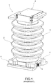
- reference sign 1 indicates a device as a whole for measuring the electrical power delivered from a high-voltage electric supply line to a railway vehicle.
- the electric supply line is for example a 25 kV AC (50 Hz) line, or a 15 kV AC (16 + 2/3 Hz) line, or a 3 kV DC line.
- the measuring device 1 includes a conventional line insulator 2 on top of which is mounted an upper container indicated as a whole using reference sign 3 and at the base of which is attached a lower base or container 4.
- Figure 2 shows schematically a block circuit diagram of a measuring device according to the present invention, whose overall structure is similar to the prior art one depicted in Figure 1 .
- Figure 3 shows a vertical cross-section of the measuring device of Figure 2 .
- the upper container 3 contains an upper horizontal metal plate 5 and a lower horizontal metal plate 6 that partially face one another ( Figure 2 ).
- a shunt resistor of predetermined value for example around 10 ⁇ .
- the upper metal plate 5 is designed to be operationally connected to a high-voltage electric supply line L, for example via a pantograph 8.
- the lower metal plate 6 is designed to be connected to the traction motors.
- the plates 5 and 6, or the terminals of the shunt resistor formed by the pins 7 in parallel, are connected to the input of a processing and amplification circuit 9.
- This circuit 9 provides a signal indicating the AC voltage on the line L to an output 9a and a signal indicating the DC voltage on said line to an output 9b.
- the signals outputted by the processing and amplification circuit 9 pass via respective amplifiers 10a, 10b to corresponding inputs of a block 11 acting as multiplexer and analogue/digital converter.
- This latter is connected to and controlled by a control and processing unit 12, provided for example using a field programmable gate array (FPGA), designed to generate signals or data indicating the intensity of the current drawn by the vehicle from the supply line L.
- FPGA field programmable gate array
- the control and processing unit 12 is connected to the input of a electrical/optical driver (converter) 13, the output of which is coupled to an optical fibre 14.
- the unit 12 is also connected to the output of a electrical/optical receiver/converter 15, the input of which is coupled to an optical fibre 16.
- the processing and amplification circuit 9 the amplifiers 10a, 10b, the A/D converter-multiplexer 11, the unit 12 and the converters 13 and 15 are shown as being outside the insulator 2, in fact these devices (and others described below) are carried on a circuit board 17 mounted in the upper end portion of the axial cavity 18 formed in the insulator 2 (see Figure 3 ).
- the direct supply voltages required by the devices carried on the circuit board 17 are obtained e.g. by a power laser receiver 19 that uses an optical fibre 20 to receive a power laser beam (for example 2 W), converting the optical energy into electrical energy, which it supplies to a supply-voltage management unit 21.
- the laser receiver 19 and the unit 21 are advantageously carried on the same circuit board 17.
- the optical fibres 14, 16 and 20 extend inside the cavity 18 of the insulator 2, from the converters 13, 15 and 19 carried on the board 17 to components (which are described below) seated inside the base body 4.
- resistive voltage divider means are connected between the board 5 and a terminal 22 that is designed to be connected to earth.
- the voltage divider means 23 comprise a plurality of voltage dividers connected operationally to the supply line L and forming separate respective connection paths to said electrical earthing terminal 22.
- two voltage dividers 23a, 23b are shown connected in parallel, each one includes respective upper resistor means 24a, 24b and lower measurement resistor means 25a, 25b, connected together in series, each one comprising one or more resistors.
- Each upper resistor means 24a, 24b have a resistance between 40 M ⁇ and 60 M ⁇ and preferably of around 50 M ⁇ .
- the upper resistor means 24a, 24b of each voltage divider 23a, 23b may have a different resistance value and the lower measurement resistor means 25a, 25b of each voltage divider 23a, 23b may have a different resistance value.
- Processing means are connected to the outputs 26a, 26b of said voltage dividers 23a, 23b and designed to generate signals or data indicating the voltage of said supply line L.
- Said processing means comprise a plurality of separate processing modules each one coupled to a respective one of said connection paths and designed to generate respective signals or data indicating the voltage of said supply line L.
- Figure 2 shows two processing modules 27a, 27b respectively coupled to lower measurement resistor means 25a, 25b. Each processing module 27a, 27b is arranged to acquire voltage readings of the voltage across the respective lower measurement resistor means 25a, 25b along the corresponding connection path.
- the upper resistor means 24a, 24b of the voltage dividers 23a, 23b have respective upper ends connected to a metal connection member 28 and lower ends connected to respective lower metal bases 30a, 30b separated from each other.
- the low metal bases 30a, 30b are attached to an electrically insulating material 29, that is essentially disc shaped, that closes the bottom of the cavity 18 formed inside the insulator 2 (see also Figure 4 ).
- the disc-shaped element 29 has at least one central opening 29a.
- the upper resistor means 24a, 24b of the voltage dividers 23a, 23b extend completely inside the cavity 18 of the insulator 2.
- the low metal bases 30a, 30b are formed as plate-like members made of electrically conductive material, and are arranged at the lower face of the disc-shaped element 29.
- the base 4 in the embodiment illustrated includes a metal body 32 substantially shaped like an inverted pan, the back wall 32a is attached to the lower end of the insulator 2 by means of bolts 33 or similar and also has a central opening 32b.
- the body 32 is closed at the bottom by a cover, indicated using reference sign 35 in Figure 4 , in which the cavity or chamber formed inside said body 32 is indicated using reference sign 36.
- the lower portion of the body 32 has a pair of horizontal fins 32c projecting transversely outwards and including respective holes 32d used for attachment to an earthing conductor.
- the body 32 On the side opposite the fins 32c, the body 32 has a tubular cylindrical extension 32e, inserted into a corresponding annular hollow formed in the wall of the insulator 2 (see Figure 4 ).
- the central portion of the back wall 32a of the metal container 32 is oriented to face the plate-like members 30a, 30b, from which it is separated by a predetermined calibrated distance.
- the plate-like members 30a, 30b and the body 32 form a pair of separated dischargers, shown schematically and indicated using reference signs 40a, 40b in Figure 2 , between the terminals 30a, 30b with the lowest potential in the upper resistor means 24a, 24b and earth E.
- Two circuit boards 37 and 38 bearing various different devices and that are described below with reference to the diagram in Figure 2 , are assembled in the cavity 36 formed in the base 4, or inside the pan-shaped body 32.
- the measurement resistor means 25a, 25b which have a resistance between 2 k ⁇ and 4 k ⁇ and preferably for example approximately 3 k ⁇ , are assembled in the base 4.
- Respective amplifiers 41a, 41b are connected across said resistor means 25a, 25b, the output of the amplifiers being connected to respective A/D converters 42a, 42b, coupled to respective control and processing units 43a, 43b, which are also for example FPGAs.
- the control and processing units 43a, 43b are arranged for calculating data indicating the voltage of the line L, based on the voltage readings acquired by each processing module 27a, 27b.
- the processing means within the base 4 include an evaluation module 50 arranged to compare the data indicating the voltage of the line L calculated by each control and processing unit 43a, 43b between them. A difference between the calculated data, greater than a predetermined threshold, is indicative of an abnormality.
- the processing means within the base 4 are further arranged for calculating the power drawn by the supply line L, as a function of the generated signals or data indicating the intensity of the current drawn by the vehicle from the supply line L and of the generated signals or data indicating the voltage of said supply line L.
- a receiver 52 such as an electrical/optical converter is provided, the input of which is connected to the optical fibre 14 through which the control and processing unit 12 sends data indicating the intensity of the current measured using the shunt resistor 5-7.
- the output of the receiver 52 is connected to a calculation unit 54, formed for example using a DSP device and a microcontroller, which also receives the data sent by the units 43a, 43b or data related thereto, such as average data, indicating the voltage of the line L, measured using the voltage dividers 23a, 23b.
- a calculation unit 54 formed for example using a DSP device and a microcontroller, which also receives the data sent by the units 43a, 43b or data related thereto, such as average data, indicating the voltage of the line L, measured using the voltage dividers 23a, 23b.
- the calculation unit 54 is also connected to a transmitter, such as an electrical/optical converter (not shown), the output of which is connected to the optical fibre 16 in order to send synchronism data to the control and processing unit 12.
- a transmitter such as an electrical/optical converter (not shown)
- the output of which is connected to the optical fibre 16 in order to send synchronism data to the control and processing unit 12.
- Various other devices may be provided inside the base 4, such as a power unit used to supply voltage to the different devices in the base 4, an electrical/optical transmitter/converter with an optical fibre output for connection to external equipment, a UART unit for connecting external devices, a network communication interface (for example Ethernet), an interface, for example an RS-485 interface, and a relay output.
- a power unit used to supply voltage to the different devices in the base 4
- an electrical/optical transmitter/converter with an optical fibre output for connection to external equipment for connection to external equipment
- a UART unit for connecting external devices
- a network communication interface for example Ethernet
- an interface for example an RS-485 interface
- relay output for example an Ethernet
- the electrical connections of the devices inside the base 4 with the "outside world" can advantageously be provided using a multi-pole electrical connector, such as the one indicated using reference sign C in Figure 1 .
- the base 4 also includes an energy source in the form of a source of optical radiation, such as a solid-state laser generator for generating a power laser beam or one or more LEDs.
- an energy source in the form of a source of optical radiation, such as a solid-state laser generator for generating a power laser beam or one or more LEDs.
- the measuring device 1 described above works essentially in the following manner:
- the control and processing unit 12 sends corresponding data to the calculation unit 54 positioned in the base 4 of the measuring device 1 via the electrical/optical converter 13, the optical fibre 14 and the optical/electrical converter or receiver 52 within said base.
- the calculation unit 54 also acquires data indicating the voltage of the line L via the voltage dividers 23a, 23b and the evaluation module 50.
- the calculation unit 54 can then calculate the power drawn by the line L, which is essentially proportional to the product of the intensity of the current drawn and of the voltage on the line. Using information on the absorbed power, the calculation unit 54 can also calculate how much energy is being drawn by the line L over a given time period, calculating the integral of the product of the power multiplied by time.
- the dischargers 40a, 40b independently or together generate a discharge to earth, thereby protecting all of the devices carried on the base 4 of the measuring device 1.
Abstract
Description
- The present invention relates to a device for measuring the electric power delivered to a railway vehicle by a high-voltage electric supply line.
- More specifically, the invention relates to an improved device for measuring the electrical power drawn by a railway vehicle according to the preamble of
claim 1. - A device of this type is described for example in European
patent application EP 1 882 954 A1 . In the device described in said document, current sensing means, a voltage divider and processing means related thereto are seated in an upper cavity (or high-voltage area) inside the insulator, separated by a second cavity (or low-voltage area) formed in the lower portion of the same insulator, which furthermore contains an electrical-to-optical energy converter designed to send power to said processing means, as well as optical/electrical converters that provide signals/data indicating the voltage and relevant current. - European
patent application EP 3 308 174 A1 discloses a device for measuring the electric power drawn by a railway vehicle from a high-voltage electric supply line including a current sensor connected to the supply line, a resistive voltage divider connected between the line and earth, first processing devices connected to the current sensor, second processing devices connected to the output of the voltage divider. The current sensor, related processing devices and the voltage divider, are seated in a cavity inside a line insulator. The terminal with the lowest potential of the voltage divider is connected to a conductive member that extends outside the cavity of the insulator. A hollow conductive body, connected to earth contains the second processing devices and is connected to the lower end of the insulator. It includes a wall arranged opposite the member to form a discharger with it. - One objective of the present invention is to provide a device for measuring the electrical power drawn by a railway vehicle, while improving the measurement of the voltage of said supply line as well as the robustness of the device against faults.
- A further object of the invention is to provide high levels of safety, even in the presence of significant surge voltages.
- This and other objectives are achieved by a device as defined in the appended
claim 1. - Preferred embodiments are defined in the dependent claims, whose content is also to be considered an integral part of the present description.
- This solution provides a device for measuring the electrical power drawn from the high-voltage electric supply line, in accordance with prevailing standards and in particular standard EN50463.
- Further characteristics and advantages of the present invention are set out in the detailed description below, provided purely as a non-limiting example, with reference to the attached drawings, in which:
-
Figure 1 is a perspective view of an electrical-power measuring device according to the prior art, -
Figure 2 is a circuit diagram partially with blocks showing a measuring device according to the present invention, -
Figure 3 is a vertical cross-section of an electrical-power measuring device according to the present invention, and -
Figure 4 is a partial magnified cut-out view of the lower portion inFigure 3 . - In the drawings,
reference sign 1 indicates a device as a whole for measuring the electrical power delivered from a high-voltage electric supply line to a railway vehicle. - The electric supply line is for example a 25 kV AC (50 Hz) line, or a 15 kV AC (16 + 2/3 Hz) line, or a 3 kV DC line.
- In the example shown, the
measuring device 1 includes aconventional line insulator 2 on top of which is mounted an upper container indicated as a whole usingreference sign 3 and at the base of which is attached a lower base orcontainer 4. -
Figure 2 shows schematically a block circuit diagram of a measuring device according to the present invention, whose overall structure is similar to the prior art one depicted inFigure 1 .Figure 3 shows a vertical cross-section of the measuring device ofFigure 2 . - With reference to
Figures 1 and3 , theupper container 3 contains an upperhorizontal metal plate 5 and a lowerhorizontal metal plate 6 that partially face one another (Figure 2 ). - Between the facing portions of the
plates pins 7 that are electrically connected to one another in parallel to jointly form a shunt resistor of predetermined value, for example around 10 µΩ. - As shown schematically in
Figure 2 , theupper metal plate 5 is designed to be operationally connected to a high-voltage electric supply line L, for example via apantograph 8. Conversely, thelower metal plate 6 is designed to be connected to the traction motors. - As shown in
Figure 2 , theplates pins 7 in parallel, are connected to the input of a processing andamplification circuit 9. Thiscircuit 9 provides a signal indicating the AC voltage on the line L to anoutput 9a and a signal indicating the DC voltage on said line to anoutput 9b. - The signals outputted by the processing and
amplification circuit 9 pass viarespective amplifiers block 11 acting as multiplexer and analogue/digital converter. This latter is connected to and controlled by a control andprocessing unit 12, provided for example using a field programmable gate array (FPGA), designed to generate signals or data indicating the intensity of the current drawn by the vehicle from the supply line L. - The control and
processing unit 12 is connected to the input of a electrical/optical driver (converter) 13, the output of which is coupled to anoptical fibre 14. - The
unit 12 is also connected to the output of a electrical/optical receiver/converter 15, the input of which is coupled to anoptical fibre 16. - Although in the diagram in
Figure 2 the processing andamplification circuit 9, theamplifiers multiplexer 11, theunit 12 and theconverters insulator 2, in fact these devices (and others described below) are carried on acircuit board 17 mounted in the upper end portion of theaxial cavity 18 formed in the insulator 2 (seeFigure 3 ). - With reference to
Figure 2 , the direct supply voltages required by the devices carried on thecircuit board 17 are obtained e.g. by apower laser receiver 19 that uses anoptical fibre 20 to receive a power laser beam (for example 2 W), converting the optical energy into electrical energy, which it supplies to a supply-voltage management unit 21. Thelaser receiver 19 and theunit 21 are advantageously carried on thesame circuit board 17. - In an embodiment not shown in the drawings, the
optical fibres cavity 18 of theinsulator 2, from theconverters board 17 to components (which are described below) seated inside thebase body 4. - With reference to
Figure 2 , resistive voltage divider means, indicated as a whole usingreference sign 23, are connected between theboard 5 and aterminal 22 that is designed to be connected to earth. - In the embodiment shown, the voltage divider means 23 comprise a plurality of voltage dividers connected operationally to the supply line L and forming separate respective connection paths to said
electrical earthing terminal 22. In the exemplary embodiment twovoltage dividers - Each upper resistor means 24a, 24b have a resistance between 40 MΩ and 60 MΩ and preferably of around 50 MΩ. The upper resistor means 24a, 24b of each
voltage divider voltage divider - Processing means are connected to the
outputs voltage dividers Figure 2 shows twoprocessing modules processing module - In the example embodiment shown, the upper resistor means 24a, 24b of the
voltage dividers metal connection member 28 and lower ends connected to respectivelower metal bases - The
low metal bases material 29, that is essentially disc shaped, that closes the bottom of thecavity 18 formed inside the insulator 2 (see alsoFigure 4 ). - The disc-
shaped element 29 has at least onecentral opening 29a. - As shown in
Figures 3 and4 , the upper resistor means 24a, 24b of thevoltage dividers cavity 18 of theinsulator 2. - With particular reference to
Figure 4 , thelow metal bases shaped element 29. - The
base 4 in the embodiment illustrated includes ametal body 32 substantially shaped like an inverted pan, theback wall 32a is attached to the lower end of theinsulator 2 by means ofbolts 33 or similar and also has acentral opening 32b. - The
body 32 is closed at the bottom by a cover, indicated usingreference sign 35 inFigure 4 , in which the cavity or chamber formed inside saidbody 32 is indicated usingreference sign 36. - In the embodiment illustrated, the lower portion of the
body 32 has a pair ofhorizontal fins 32c projecting transversely outwards and includingrespective holes 32d used for attachment to an earthing conductor. - On the side opposite the
fins 32c, thebody 32 has a tubularcylindrical extension 32e, inserted into a corresponding annular hollow formed in the wall of the insulator 2 (seeFigure 4 ). - The central portion of the
back wall 32a of themetal container 32 is oriented to face the plate-like members - As a whole, the plate-
like members wall 32a of this latter) form a pair of separated dischargers, shown schematically and indicated usingreference signs Figure 2 , between theterminals - In the event of a surge that exceeds a predetermined value, between the plate-
like members wall 32a of thecontainer 32, an electrical charge is generated that prevents damage being caused to the devices seated in thecavity 36 of thebase - Two
circuit boards Figure 2 , are assembled in thecavity 36 formed in thebase 4, or inside thepan-shaped body 32. - As shown in this diagram, the measurement resistor means 25a, 25b, which have a resistance between 2 kΩ and 4 kΩ and preferably for example approximately 3 kΩ, are assembled in the
base 4. -
Respective amplifiers D converters processing units processing units processing module - The processing means within the
base 4 include anevaluation module 50 arranged to compare the data indicating the voltage of the line L calculated by each control andprocessing unit - The processing means within the
base 4 are further arranged for calculating the power drawn by the supply line L, as a function of the generated signals or data indicating the intensity of the current drawn by the vehicle from the supply line L and of the generated signals or data indicating the voltage of said supply line L. For this purpose, areceiver 52, such as an electrical/optical converter is provided, the input of which is connected to theoptical fibre 14 through which the control andprocessing unit 12 sends data indicating the intensity of the current measured using the shunt resistor 5-7. - The output of the
receiver 52 is connected to acalculation unit 54, formed for example using a DSP device and a microcontroller, which also receives the data sent by theunits voltage dividers - The
calculation unit 54 is also connected to a transmitter, such as an electrical/optical converter (not shown), the output of which is connected to theoptical fibre 16 in order to send synchronism data to the control andprocessing unit 12. - Various other devices may be provided inside the
base 4, such as a power unit used to supply voltage to the different devices in thebase 4, an electrical/optical transmitter/converter with an optical fibre output for connection to external equipment, a UART unit for connecting external devices, a network communication interface (for example Ethernet), an interface, for example an RS-485 interface, and a relay output. - The electrical connections of the devices inside the
base 4 with the "outside world" can advantageously be provided using a multi-pole electrical connector, such as the one indicated using reference sign C inFigure 1 . - The
base 4 also includes an energy source in the form of a source of optical radiation, such as a solid-state laser generator for generating a power laser beam or one or more LEDs. - When in operation, the measuring
device 1 described above works essentially in the following manner:
The devices carried on thecircuit board 17, which is positioned in the upper portion of the internal cavity of theinsulator 2, measure the intensity of the current drawn by the line L using the resistive shunt device 5-7. The control andprocessing unit 12 sends corresponding data to thecalculation unit 54 positioned in thebase 4 of the measuringdevice 1 via the electrical/optical converter 13, theoptical fibre 14 and the optical/electrical converter orreceiver 52 within said base. - The
calculation unit 54 also acquires data indicating the voltage of the line L via thevoltage dividers evaluation module 50. - The
calculation unit 54 can then calculate the power drawn by the line L, which is essentially proportional to the product of the intensity of the current drawn and of the voltage on the line. Using information on the absorbed power, thecalculation unit 54 can also calculate how much energy is being drawn by the line L over a given time period, calculating the integral of the product of the power multiplied by time. - In the event of a surge greater than a predetermined value, the
dischargers base 4 of the measuringdevice 1. - Naturally, notwithstanding the invention principle, the means of implementation and the specific embodiments may vary greatly from that described and illustrated purely by way of a non-limiting example, without thereby moving outside the scope of the invention as defined in the attached claims.
Claims (8)
- Device (1) for measuring the electric power delivered to a railway vehicle by a high voltage electric supply line (L), comprising:resistive voltage divider means (23) connected operationally between said supply line (L) and an electric earthing terminal (22; 32c), andprocessing means connected to the output (26a, 26b) of said voltage divider means (23) and designed to generate signals or data indicating the voltage of said supply line (L),characterised in that said resistive voltage divider means (23) comprise a plurality of voltage dividers (23a, 23b) connected operationally to said supply line (L) and forming separate respective connection paths to said electrical earthing terminal (22; 32c), andin that said processing means comprise a plurality of separate processing modules (41a, 42a, 43a; 41b, 42b, 43b) each one coupled to a respective one of said connection paths and designed to generate respective signals or data indicating the voltage of said supply line (L).
- Device (1) according to claim 1, wherein each voltage divider (23a; 23b) includes upper voltage drop resistor means (24a; 24b) and lower measurement resistor means (25a; 25b), connected in series along a respective connection path, each processing module (41a, 42a, 43a; 41b, 42b, 43b) being arranged to acquire voltage readings of the voltage across respective lower measurement resistor means (25a; 25b) along a respective connection path.
- Device (1) according to claim 2, wherein each processing module (41a, 42a, 43a; 41b, 42b, 43b) includes amplifier means (41a; 41b) connected across said respective lower measurement resistor means (25a; 25b), the output of the amplifier (41a; 41b) being coupled through A/D converter means (42a; 42b) to a control and processing unit (43a; 43b) arranged for calculating data indicating the voltage of the line (L) based on said voltage readings.
- Device (1) according to claim 3, wherein said processing means include an evaluation module (50) arranged to compare the data indicating the voltage of the line (L) calculated by each control and processing unit (41a, 42a, 43a; 41b, 42b, 43b) between them, wherein a difference between the calculated data, greater than a predetermined threshold, is indicative of an abnormality.
- Device (1) according to any one of the preceding claims, wherein said upper resistor means (24a; 24b) of each voltage divider (23a; 23b) have a different resistance value and said lower measurement resistor means (25a; 25b) of each voltage divider (23a; 23b) have a different resistance value.
- Device (1) according to any one of the preceding claims, wherein said voltage divider means (23) are arranged in a cavity (18) inside a line insulator (2) and the terminal (30a; 30b) with the lowest potential of each voltage divider (23a; 23b) is arranged at a predetermined distance from a body (32) made of electrically conductive material, arranged at a lower end of said insulator (2) and outside the cavity (18) of said insulator (2), which body (32) is adapted to be operatively connected to earth (E) and in which body (32) there are arranged said processing means, such as to form therewith respective separate dischargers (40a; 40b) capable of generating an electric discharge when the voltage across at least one of said dischargers (40a; 40b) exceeds a predetermined value.
- Device (1) according to claim 6, wherein each terminal (30a; 30b) with the lowest potential of each voltage divider (23a; 23b) is connected to a respective plate-like member (30a; 30b) made of electrically conductive material that extends outside the cavity (18) of said insulator (2), and said body (32) made of electrically conductive material, arranged at a lower end of said insulator (2), is a hollow body (32), said hollow body (32) including a plate-like wall (32a) arranged to face said plate-like members (30a; 30b) at a predetermined distance therefrom.
- Device (1) according to any one of the preceding claims, further comprising current sensing means (5-7) connected operationally to said supply line (L) and second processing means (9-13) connected to said current sensing means (5-7) and designed to generate signals or data indicating the intensity of the current drawn by the vehicle from the supply line (L), wherein said processing means are further arranged for calculating the power drawn by the supply line (L), as a function of the generated signals or data indicating the intensity of the current drawn by the vehicle from the supply line (L) and of the generated signals or data indicating the voltage of said supply line (L).
Priority Applications (5)
| Application Number | Priority Date | Filing Date | Title |
|---|---|---|---|
| EP19150985.0A EP3680672B1 (en) | 2019-01-09 | 2019-01-09 | An improved device for measuring the electric power drawn by a railway vehicle from a high-voltage electric supply line |
| CN202080008588.9A CN113272662A (en) | 2019-01-09 | 2020-01-08 | Improved device for measuring the power consumed by a railway vehicle from a high-voltage power supply line |
| CA3126318A CA3126318A1 (en) | 2019-01-09 | 2020-01-08 | An improved device for measuring the electric power drawn by a railway vehicle from a high-voltage electric supply line |
| PCT/EP2020/050263 WO2020144205A1 (en) | 2019-01-09 | 2020-01-08 | An improved device for measuring the electric power drawn by a railway vehicle from a high-voltage electric supply line |
| US17/422,162 US11867727B2 (en) | 2019-01-09 | 2020-01-08 | Device for measuring the electric power drawn by a railway vehicle from a high-voltage electric supply line |
Applications Claiming Priority (1)
| Application Number | Priority Date | Filing Date | Title |
|---|---|---|---|
| EP19150985.0A EP3680672B1 (en) | 2019-01-09 | 2019-01-09 | An improved device for measuring the electric power drawn by a railway vehicle from a high-voltage electric supply line |
Publications (2)
| Publication Number | Publication Date |
|---|---|
| EP3680672A1 true EP3680672A1 (en) | 2020-07-15 |
| EP3680672B1 EP3680672B1 (en) | 2023-11-15 |
Family
ID=65011906
Family Applications (1)
| Application Number | Title | Priority Date | Filing Date |
|---|---|---|---|
| EP19150985.0A Active EP3680672B1 (en) | 2019-01-09 | 2019-01-09 | An improved device for measuring the electric power drawn by a railway vehicle from a high-voltage electric supply line |
Country Status (5)
| Country | Link |
|---|---|
| US (1) | US11867727B2 (en) |
| EP (1) | EP3680672B1 (en) |
| CN (1) | CN113272662A (en) |
| CA (1) | CA3126318A1 (en) |
| WO (1) | WO2020144205A1 (en) |
Citations (10)
| Publication number | Priority date | Publication date | Assignee | Title |
|---|---|---|---|---|
| US20030228503A1 (en) * | 2002-04-26 | 2003-12-11 | Martin Georgii | Fuel cell system and method for voltage monitoring for a fuel cell system |
| EP1882954A1 (en) | 2006-07-25 | 2008-01-30 | Alstom Transport S.A. | Device for measuring the electrical energy provided to a railway traction engine |
| EP2156529A1 (en) * | 2007-06-07 | 2010-02-24 | ABB Technology AG | Voltage measurements of electrically conducting elements in systems for controlling electrical processes |
| US20140266127A1 (en) * | 2013-03-14 | 2014-09-18 | Qualcomm Incorporated | Low power and dynamic voltage divider and monitoring circuit |
| CN203909129U (en) * | 2014-06-30 | 2014-10-29 | 陕西和硕电气有限公司 | Capacitive voltage divider type voltage sensor |
| JP5955507B2 (en) * | 2011-02-14 | 2016-07-20 | トヨタ自動車株式会社 | Voltage detection circuit and voltage detection device for power storage device, and vehicle equipped with the same |
| WO2016203360A1 (en) * | 2015-06-15 | 2016-12-22 | Casram Rail S.P.A. | Device for measuring the electric power drawn by a railway vehicle from a high-voltage electric supply line |
| WO2017079143A1 (en) * | 2015-11-05 | 2017-05-11 | Panduit Corp. | Isolation and validation techniques for voltage detector |
| JP2018125991A (en) * | 2017-02-02 | 2018-08-09 | 住友重機械工業株式会社 | Work machine and motor drive system |
| CN108562786A (en) * | 2018-01-17 | 2018-09-21 | 广州小鹏汽车科技有限公司 | A kind of high pressure sampling system and method |
Family Cites Families (1)
| Publication number | Priority date | Publication date | Assignee | Title |
|---|---|---|---|---|
| CN106226603B (en) * | 2016-07-26 | 2020-10-20 | 中国电力科学研究院 | Corona loss measurement system and method for high-voltage alternating-current transmission line |
-
2019
- 2019-01-09 EP EP19150985.0A patent/EP3680672B1/en active Active
-
2020
- 2020-01-08 CA CA3126318A patent/CA3126318A1/en active Pending
- 2020-01-08 WO PCT/EP2020/050263 patent/WO2020144205A1/en active Application Filing
- 2020-01-08 US US17/422,162 patent/US11867727B2/en active Active
- 2020-01-08 CN CN202080008588.9A patent/CN113272662A/en active Pending
Patent Citations (11)
| Publication number | Priority date | Publication date | Assignee | Title |
|---|---|---|---|---|
| US20030228503A1 (en) * | 2002-04-26 | 2003-12-11 | Martin Georgii | Fuel cell system and method for voltage monitoring for a fuel cell system |
| EP1882954A1 (en) | 2006-07-25 | 2008-01-30 | Alstom Transport S.A. | Device for measuring the electrical energy provided to a railway traction engine |
| EP2156529A1 (en) * | 2007-06-07 | 2010-02-24 | ABB Technology AG | Voltage measurements of electrically conducting elements in systems for controlling electrical processes |
| JP5955507B2 (en) * | 2011-02-14 | 2016-07-20 | トヨタ自動車株式会社 | Voltage detection circuit and voltage detection device for power storage device, and vehicle equipped with the same |
| US20140266127A1 (en) * | 2013-03-14 | 2014-09-18 | Qualcomm Incorporated | Low power and dynamic voltage divider and monitoring circuit |
| CN203909129U (en) * | 2014-06-30 | 2014-10-29 | 陕西和硕电气有限公司 | Capacitive voltage divider type voltage sensor |
| WO2016203360A1 (en) * | 2015-06-15 | 2016-12-22 | Casram Rail S.P.A. | Device for measuring the electric power drawn by a railway vehicle from a high-voltage electric supply line |
| EP3308174A1 (en) | 2015-06-15 | 2018-04-18 | Casram Rail S.p.A. | Device for measuring the electric power drawn by a railway vehicle from a high-voltage electric supply line |
| WO2017079143A1 (en) * | 2015-11-05 | 2017-05-11 | Panduit Corp. | Isolation and validation techniques for voltage detector |
| JP2018125991A (en) * | 2017-02-02 | 2018-08-09 | 住友重機械工業株式会社 | Work machine and motor drive system |
| CN108562786A (en) * | 2018-01-17 | 2018-09-21 | 广州小鹏汽车科技有限公司 | A kind of high pressure sampling system and method |
Also Published As
| Publication number | Publication date |
|---|---|
| CN113272662A (en) | 2021-08-17 |
| EP3680672B1 (en) | 2023-11-15 |
| CA3126318A1 (en) | 2020-07-16 |
| WO2020144205A1 (en) | 2020-07-16 |
| US11867727B2 (en) | 2024-01-09 |
| US20220113336A1 (en) | 2022-04-14 |
Similar Documents
| Publication | Publication Date | Title |
|---|---|---|
| EP3308174B1 (en) | Device for measuring the electric power drawn by a railway vehicle from a high-voltage electric supply line | |
| EP2689256B1 (en) | High voltage measurement systems | |
| US20220317158A1 (en) | Adjustable voltage sensor | |
| CN112858785A (en) | Circuit arrangement with active voltage measurement for determining the insulation resistance in an ungrounded power supply system with respect to the ground potential | |
| EP3680672B1 (en) | An improved device for measuring the electric power drawn by a railway vehicle from a high-voltage electric supply line | |
| KR101348990B1 (en) | High speed current shunt | |
| US10684315B2 (en) | System for indicating the presence of voltage in a high-voltage network | |
| RU2783561C1 (en) | Improved device for measuring electrical power consumed by railway vehicle from high-voltage power supply line | |
| CN109387751A (en) | A kind of line fault monitoring device | |
| JP2022513891A (en) | Insulator for elevated power line conductors | |
| KR101957949B1 (en) | Distributing board for measuring multi-load power loss in live state | |
| CN109923429B (en) | Dual-voltage battery with current sensor and calibration method for dual-voltage battery | |
| US11835571B2 (en) | Device for detecting a fault in an electrical network, electrical network or equipment comprising such a device and method for detecting a fault | |
| US20230384350A1 (en) | Adjustable voltage sensor | |
| CN109687539B (en) | Multi-sensor grouping power supply device and system | |
| KR20190038165A (en) | Distributing board for remote circuit detection in live wire | |
| KR20180086875A (en) | measuring system of dangerous voltage | |
| SU924630A2 (en) | Device for checking grounding circuit | |
| CN210119519U (en) | Measuring device and transducer arrangement for measuring current in an electrical line | |
| US497482A (en) | Shunt for electric light and power stations | |
| De Lorenzo | LINEAR-LOG RADIATION MONITOR, ORNL MODEL Q-2353. | |
| CZ7125U1 (en) | Device for continuous monitoring ground resistance or line resistance | |
| SE468183B (en) | Arrangement for indicating the presence/absence and, with acceptable accuracy, the magnitude of electric voltage in a conductor |
Legal Events
| Date | Code | Title | Description |
|---|---|---|---|
| PUAI | Public reference made under article 153(3) epc to a published international application that has entered the european phase |
Free format text: ORIGINAL CODE: 0009012 |
|
| STAA | Information on the status of an ep patent application or granted ep patent |
Free format text: STATUS: THE APPLICATION HAS BEEN PUBLISHED |
|
| AK | Designated contracting states |
Kind code of ref document: A1 Designated state(s): AL AT BE BG CH CY CZ DE DK EE ES FI FR GB GR HR HU IE IS IT LI LT LU LV MC MK MT NL NO PL PT RO RS SE SI SK SM TR |
|
| AX | Request for extension of the european patent |
Extension state: BA ME |
|
| STAA | Information on the status of an ep patent application or granted ep patent |
Free format text: STATUS: REQUEST FOR EXAMINATION WAS MADE |
|
| 17P | Request for examination filed |
Effective date: 20200810 |
|
| RBV | Designated contracting states (corrected) |
Designated state(s): AL AT BE BG CH CY CZ DE DK EE ES FI FR GB GR HR HU IE IS IT LI LT LU LV MC MK MT NL NO PL PT RO RS SE SI SK SM TR |
|
| RIN1 | Information on inventor provided before grant (corrected) |
Inventor name: BATTISTELLA, DENIS Inventor name: LOVATI, VALTER Inventor name: CHIANESE, ALESSANDRO |
|
| STAA | Information on the status of an ep patent application or granted ep patent |
Free format text: STATUS: EXAMINATION IS IN PROGRESS |
|
| 17Q | First examination report despatched |
Effective date: 20221213 |
|
| GRAP | Despatch of communication of intention to grant a patent |
Free format text: ORIGINAL CODE: EPIDOSNIGR1 |
|
| STAA | Information on the status of an ep patent application or granted ep patent |
Free format text: STATUS: GRANT OF PATENT IS INTENDED |
|
| RIC1 | Information provided on ipc code assigned before grant |
Ipc: G01R 21/06 20060101ALN20230524BHEP Ipc: G01R 35/00 20060101ALN20230524BHEP Ipc: G01R 15/04 20060101AFI20230524BHEP |
|
| INTG | Intention to grant announced |
Effective date: 20230620 |
|
| GRAS | Grant fee paid |
Free format text: ORIGINAL CODE: EPIDOSNIGR3 |
|
| GRAA | (expected) grant |
Free format text: ORIGINAL CODE: 0009210 |
|
| STAA | Information on the status of an ep patent application or granted ep patent |
Free format text: STATUS: THE PATENT HAS BEEN GRANTED |
|
| AK | Designated contracting states |
Kind code of ref document: B1 Designated state(s): AL AT BE BG CH CY CZ DE DK EE ES FI FR GB GR HR HU IE IS IT LI LT LU LV MC MK MT NL NO PL PT RO RS SE SI SK SM TR |
|
| REG | Reference to a national code |
Ref country code: CH Ref legal event code: EP Ref country code: GB Ref legal event code: FG4D |
|
| REG | Reference to a national code |
Ref country code: DE Ref legal event code: R096 Ref document number: 602019041306 Country of ref document: DE |
|
| REG | Reference to a national code |
Ref country code: IE Ref legal event code: FG4D |
|
| REG | Reference to a national code |
Ref country code: SE Ref legal event code: TRGR |
|
| P01 | Opt-out of the competence of the unified patent court (upc) registered |
Effective date: 20240124 |
|
| REG | Reference to a national code |
Ref country code: LT Ref legal event code: MG9D |
|
| REG | Reference to a national code |
Ref country code: NL Ref legal event code: MP Effective date: 20231115 |
|
| PG25 | Lapsed in a contracting state [announced via postgrant information from national office to epo] |
Ref country code: GR Free format text: LAPSE BECAUSE OF FAILURE TO SUBMIT A TRANSLATION OF THE DESCRIPTION OR TO PAY THE FEE WITHIN THE PRESCRIBED TIME-LIMIT Effective date: 20240216 |
|
| PG25 | Lapsed in a contracting state [announced via postgrant information from national office to epo] |
Ref country code: IS Free format text: LAPSE BECAUSE OF FAILURE TO SUBMIT A TRANSLATION OF THE DESCRIPTION OR TO PAY THE FEE WITHIN THE PRESCRIBED TIME-LIMIT Effective date: 20240315 |
|
| PG25 | Lapsed in a contracting state [announced via postgrant information from national office to epo] |
Ref country code: LT Free format text: LAPSE BECAUSE OF FAILURE TO SUBMIT A TRANSLATION OF THE DESCRIPTION OR TO PAY THE FEE WITHIN THE PRESCRIBED TIME-LIMIT Effective date: 20231115 |
|
| REG | Reference to a national code |
Ref country code: AT Ref legal event code: UEP Ref document number: 1632242 Country of ref document: AT Kind code of ref document: T Effective date: 20231115 |
|
| PG25 | Lapsed in a contracting state [announced via postgrant information from national office to epo] |
Ref country code: NL Free format text: LAPSE BECAUSE OF FAILURE TO SUBMIT A TRANSLATION OF THE DESCRIPTION OR TO PAY THE FEE WITHIN THE PRESCRIBED TIME-LIMIT Effective date: 20231115 |
|
| PGFP | Annual fee paid to national office [announced via postgrant information from national office to epo] |
Ref country code: ES Payment date: 20240216 Year of fee payment: 6 |
|
| PGFP | Annual fee paid to national office [announced via postgrant information from national office to epo] |
Ref country code: AT Payment date: 20240207 Year of fee payment: 6 |