EP3680644A1 - Analysevorrichtung - Google Patents
Analysevorrichtung Download PDFInfo
- Publication number
- EP3680644A1 EP3680644A1 EP19205528.3A EP19205528A EP3680644A1 EP 3680644 A1 EP3680644 A1 EP 3680644A1 EP 19205528 A EP19205528 A EP 19205528A EP 3680644 A1 EP3680644 A1 EP 3680644A1
- Authority
- EP
- European Patent Office
- Prior art keywords
- fluid
- measuring
- rinsing
- optical
- analysis device
- Prior art date
- Legal status (The legal status is an assumption and is not a legal conclusion. Google has not performed a legal analysis and makes no representation as to the accuracy of the status listed.)
- Granted
Links
Images




Classifications
-
- G—PHYSICS
- G01—MEASURING; TESTING
- G01N—INVESTIGATING OR ANALYSING MATERIALS BY DETERMINING THEIR CHEMICAL OR PHYSICAL PROPERTIES
- G01N21/00—Investigating or analysing materials by the use of optical means, i.e. using sub-millimetre waves, infrared, visible or ultraviolet light
- G01N21/01—Arrangements or apparatus for facilitating the optical investigation
- G01N21/15—Preventing contamination of the components of the optical system or obstruction of the light path
-
- G—PHYSICS
- G01—MEASURING; TESTING
- G01N—INVESTIGATING OR ANALYSING MATERIALS BY DETERMINING THEIR CHEMICAL OR PHYSICAL PROPERTIES
- G01N21/00—Investigating or analysing materials by the use of optical means, i.e. using sub-millimetre waves, infrared, visible or ultraviolet light
- G01N21/84—Systems specially adapted for particular applications
- G01N21/85—Investigating moving fluids or granular solids
-
- G—PHYSICS
- G01—MEASURING; TESTING
- G01N—INVESTIGATING OR ANALYSING MATERIALS BY DETERMINING THEIR CHEMICAL OR PHYSICAL PROPERTIES
- G01N21/00—Investigating or analysing materials by the use of optical means, i.e. using sub-millimetre waves, infrared, visible or ultraviolet light
- G01N21/84—Systems specially adapted for particular applications
- G01N21/85—Investigating moving fluids or granular solids
- G01N2021/8557—Special shaping of flow, e.g. using a by-pass line, jet flow, curtain flow
Definitions
- the present invention relates to an analysis device for analyzing a measuring fluid that flows through a flow channel, with an optical measuring unit that has at least one optical interface for metrologically connecting the optical measuring unit to the flow channel, and with a flushing device for flushing the at least one optical interface with a flushing fluid.
- the measuring fluid and the flushing fluid can be gases or liquids.
- the optical measuring unit usually comprises a transmitter for emitting electromagnetic rays into the flow channel and a receiver for receiving transmitted, reflected or scattered electromagnetic radiation.
- Optical measuring units which are based on the detection of transmitted light, are often designed in two parts and are attached to opposite wall sections of the flow channel.
- Optical measuring units are also known which have a combination of transmitter and receiver and an opposing reflector.
- the optical interface can be the front of a viewing window facing the measuring fluid flow, which separates the optical measuring unit from the measuring fluid.
- Generic analysis devices are for example in the EP 2 428 793 A1 and in the DE 20 2015 102 319 U1 disclosed.
- Rinsing the optical interface with a rinsing fluid serves to keep the viewing window of the optical measuring unit clean and, in particular, prevents the optical interface from becoming dirty, misted up or corroded during operation of the analysis device. Such contamination is a considerable problem in practice because it can degrade the signal that can be evaluated, impair the accuracy of the measurement, or even falsify the measurement. Ambient air, compressed air, steam, nitrogen or flushing liquids can be used in particular as flushing fluids.
- the flushing device is conventionally connected to a suitable flushing fluid source and has a flushing fluid supply unit that supplies the flushing fluid to the optical interface.
- the problem with analysis devices with flushing devices is that a flushing fluid source has to be provided on site, which is complex.
- the provision of pumps, blowers, storage containers, gas bottles, filters, separators, pipelines, valves and the like is associated with considerable additional costs.
- ambient air which is used, for example, as a purge gas, can introduce undesirable moisture, which can lead to condensation and can therefore also promote corrosion of the components involved.
- the flushing fluid must also not get into the measuring section, because it could otherwise impair the analysis. It is a challenge, on the one hand, to provide adequate rinsing under all operating conditions and, on the other hand, to prevent rinsing fluid from entering the measuring section.
- the measurement window can be set back so that it is not directly exposed to the measurement fluid flow.
- the optical interface can also have a coating which counteracts corrosion, fogging or adherence of particles.
- the optical interface can also have a coating which counteracts corrosion, fogging or adherence of particles.
- Heating the measuring window can also be considered to prevent fogging and corrosion. In the case of liquid or solid particles in particular, however, this measure is not sufficient to reliably prevent pollution.
- Filters can also be used that surround the measuring area and thereby prevent dirt from reaching the optical interface. However, filters of this type lead to an increase in the response time, which even increases as the filter progressively becomes dirty. Depending on the application, the filter can even become completely blocked, so that maintenance is required.
- the rinsing device is designed to prepare measuring fluid and to use the prepared measuring fluid as rinsing fluid and to introduce it into a rinsing area adjacent to the optical interface.
- the measuring fluid itself is used to rinse the optical interface after suitable processing. It is therefore not necessary to provide an external source of flushing fluid.
- flushing fluid gets into the measuring section, since it naturally has the same chemical composition as the measuring fluid. The measurement is therefore not only much easier to carry out than was previously possible, but there is also an increased level of reliability. If the amount of flushing fluid to be dispensed per unit of time changes during the operation of the analysis device, this has only a relatively minor influence on the measurement.
- the optical measuring unit preferably defines a measuring range which can be at least essentially freely flowed through.
- the measuring range which forms at least part of the measuring section, is therefore not shielded by filters or the like, so that there is a particularly short response time.
- the measurement area is preferably arranged centrally with respect to the cross section of the flow channel.
- the rinsing area can be separated from the measuring area by shielding and / or filtering means.
- the optical interface can be shielded from the measuring fluid flow by a pipe socket or can be arranged so as to be set back with respect to the wall of the flow channel, by the duration of action of the Extend rinsing fluids.
- the shielded or recessed area can form the rinsing area.
- the rinsing device is designed to filter the measuring fluid for processing.
- the filtering can be carried out by means of a metal, plastic or ceramic sinter filter, a membrane, a fabric and / or a perforated screen. Dirt particles contained in the measuring fluid flow can thus be kept away from the optical interface.
- the rinsing device can be designed to subject the measuring fluid to a separation process for processing.
- the rinsing fluid can be kept at least substantially free of liquid drops and / or solid particles.
- the rinsing device can in particular be provided with a filter, a membrane, a nozzle, in particular a Venturi nozzle, a baffle plate and / or a cyclone.
- the rinsing device can be designed to heat or cool the measuring fluid for processing. For example, excessive condensation can be avoided with heated measuring fluid.
- the rinsing device is designed to collect a partial flow of the measuring fluid flowing through the flow channel, to process it and to introduce it into the rinsing area using the flow energy.
- the collection can take place with an opening that is at least substantially aligned against a main flow direction of the flow channel. If necessary, a funnel can be arranged at the opening. Due to the utilization of the flow energy, a pump or a blower of the flushing device can be designed for a reduced output, which saves costs. In certain applications, it can be that no pump or blower is required to introduce the flushing fluid into the flushing area.
- the rinsing device is designed to remove measurement fluid from the flow channel, to prepare the removed measurement fluid inside or outside the flow channel and to supply the prepared measurement fluid to the rinsing area by means of at least one supply line.
- This enables particularly effective rinsing.
- removal is possible at one or more removal points.
- the relevant removal opening can be arranged in such a way that a lateral removal takes place, that is to say that the removal direction runs transversely to a main flow direction of the flow channel.
- the removal point and the associated removal opening can also be arranged in such a way that the removal direction runs parallel to the main flow direction.
- the rinsing device is designed to remove the measurement fluid at a point protected against contamination and thereby to prepare it.
- the removal can take place on a side of the flow channel facing away from the flow, at a point protected from direct flow or at a point with little particles.
- Such treatment may be sufficient for certain applications.
- filtering, heating, cooling or separation can also be provided.
- the optical measuring unit comprises two optical interfaces, the rinsing device being designed to deliver the prepared measuring fluid as rinsing fluid into respective rinsing areas adjacent to the optical interfaces.
- the measurement window of a transmitter and a receiver or a reflector can thus be protected equally.
- the two optical interfaces are arranged opposite one another and a measuring area of the optical measuring unit is formed between the optical interfaces.
- the measuring range can preferably be flowed through at least essentially freely.
- the rinsing areas can be located at the beginning and at the end of the measuring range, which do not necessarily have to be freely flowable. Since the rinsing fluid does not differ chemically from the measuring fluid, the effective measuring distance is maximum.
- the rinsing device can be designed to actively introduce the processed measuring fluid into the rinsing area, in particular to blow it in or to inject it.
- the rinsing device can be designed to actively draw off measuring fluid from the flow channel, in particular from a measuring area that can be flowed through at least essentially freely.
- the flushing device can comprise a pump or a blower.
- the introduction and / or the suction can also take place with additional use of the flow energy.
- the invention also relates to a method for analyzing a measuring fluid which flows through a flow channel by means of an optical measuring unit which has at least one optical interface for measuring-technical connection of the optical measuring unit to the flow channel, the at least one optical interface using a flushing device with a flushing fluid is rinsed.
- measurement fluid is prepared and the prepared measurement fluid is introduced as a rinsing fluid into a rinsing area adjacent to the optical interface.
- a first partial flow of the measuring fluid flowing through the flow channel is preferably collected, processed and introduced into the rinsing area, and a measuring area of the optical measuring unit that is separate from the rinsing area is exposed to a separate second partial flow of the measuring fluid flowing through the flow channel.
- this reliably counteracts contamination of the optical interface, while on the other hand the response time is kept short due to the unimpeded second partial flow.
- a method according to the invention can in particular be carried out with an analysis device according to the invention, which is designed as described above.
- all the steps disclosed above with reference to the analysis device can be carried out in a method according to the invention.
- Fig. 1 shows in simplified form part of a flow channel 11, which can be, for example, an exhaust gas chimney or a flare tube.
- a gas stream 12 moves in the flow channel 11 along a main flow direction.
- an analysis device 13 which is attached to the flow channel 11 and is designed according to the prior art, is provided, which comprises a two-part optical measuring unit 15 in a basically known manner.
- the optical measuring unit 15 comprises a transmitter module 17a with a radiation transmitter, not shown, and a receiver module 17b with a radiation receiver, not shown.
- the metrological connection of the transmitter module 17a and the receiver module 17b to the flow channel 11 takes place by means of viewing windows or process windows, the front sides of which form respective optical interfaces 20.
- the measuring section 19 is surrounded by a filter 21.
- 20 dead spaces 25 are provided in front of the optical interfaces. Because of the full Shielding the measuring section 19 by the filter 21 is the response time of the in Fig. 1 shown analysis device 13 relatively long. In addition, there is a risk that the filter 21 will become clogged over time, as a result of which a reliable measurement is no longer possible.
- a rinsing device 27 is provided here, which can be connected to a source of detergent (not shown), for example in the form of a pressure vessel, and is designed to blow rinsing fluid such as nitrogen into the vicinity of the optical interfaces 20.
- the measuring section 19 is shortened here, because on both sides of the measuring section 19 there are rinsing areas 29 in which there is no measuring fluid, but only the differently composed rinsing fluid.
- Fig. 3 shows an analysis device 33 according to the invention which, like that in FIG Fig. 2 shown analysis device 13 'has a measuring section 19, which is located between respective optical interfaces 20.
- the analysis device 33 is designed as a reflection arrangement, but could also be designed as a transmission arrangement.
- the rinsing device 37 is not connected to an external rinsing fluid source here, but is designed to prepare measuring fluid and to introduce the prepared measuring fluid as rinsing fluid into respective rinsing areas 39 adjacent to the optical interfaces 20.
- a fluid inlet 40 shown here as a funnel
- measuring fluid is formed on a housing 38 of the optical measuring unit 15 and is connected to a further supply line 41.
- the feed line 41 has a first outlet 42 and a second outlet 43, each of which opens into a rinsing area 39.
- the rinsing areas 39 directly adjoin the optical interfaces 20 on. If necessary, the first outlet 42 and the second outlet 43 can be provided with nozzles.
- a preparation filter 45 is provided in the area of the inlet 40.
- This can be a metal filter, a plastic filter, a ceramic sintered filter or a membrane.
- a fabric or a perforated screen could also be provided as a filter.
- a combination of different filters can also be provided.
- the transport of the processed measuring fluid via the feed line 41 to the outlets 42, 43 can be active, i.e. by means of a pump or a blower, and / or using the flow energy. Since the rinsing fluid is cleaned measuring fluid, the entire space between the two optical interfaces 20 forms the measuring section 19.
- a change in the amount of rinsing fluid dispensed per time has no appreciable effects on the measurement, but at most on the response behavior or the degree of contamination.
- the measuring section 19 is not surrounded by a filter, so that the measuring fluid can flow through the space between the two optical interfaces 20 at least essentially free of charge.
- the analysis device 33 according to the invention has a particularly fast response behavior.
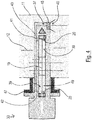
- FIG. 4 An analysis device 33 according to the invention is shown, which is designed in the same way as that in FIG Fig. 3 shown device, but in contrast to this is mounted on a flange 47 which is set back against a wall of the flow channel 11. Because of this assembly, a dead space 49 is formed, into which the measuring fluid can only penetrate with difficulty. Due to the flushing of the dead space 49 with measuring fluid by means of the flushing device 37, however, it is ensured that the entire measuring section 19 is filled with measuring fluid.
- the inventive analysis device 53 shown is the housing 38 of the optical measuring unit 15 as in the case of FIG Fig. 1 shown analysis device 13 carried out in two parts, that is, there is a so-called "cross-duct" arrangement with a transmitter module 17a and a receiver module 17b.
- the measurement fluid to be prepared is removed from the flow channel 11 by means of a removal device 55 separate from the optical measurement unit 15. It is then fed to the transmitter module 17a and the receiver module 17b by means of a feed line 41 and is introduced into the rinsing areas 39 immediately before the respective optical interfaces 20.
- the removal device 55 has an inlet 60 which has an inlet opening running transversely to the main flow direction of the flow channel 11.
- the flushing device 37 ' is the one in Fig. 5 Analyzer 53 shown equipped with a pump or a blower, which in Fig. 5 but is not shown.
- the conditioning filter 45 is arranged in the removal device 55 as shown.
- FIG Fig. 6 Another embodiment of an analysis device 63 according to the invention is shown in FIG Fig. 6 shown.
- the optical measuring unit 15 is similar to that in FIG Fig. 2 designed in one piece, that is, as a so-called "lance".
- the flushing device 67 is designed without a feed line system.
- openings 69 are provided in the housing 38 of the optical measuring unit 15, in which respective treatment filters 45 are arranged.
- the openings 69 open directly into the rinsing areas 39.
- the rinsing of the optical interfaces 20 thus takes place using the flow energy of the measuring fluid, preferably without active fluid transport by means of pumps, blowers or the like.
- the measuring area 70 located between the two rinsing areas 39 is at least essentially free to flow through. For this purpose, a corresponding recess can be provided in the housing 38.
- further means for processing the measuring fluid can be used be provided, for example particle separators, heating devices or cooling devices.
- the supply of the flushing fluid can be made more complex, for example by providing an annular arrangement of outlet openings in the vicinity of an optical interface 20.
Landscapes
- Physics & Mathematics (AREA)
- Health & Medical Sciences (AREA)
- Life Sciences & Earth Sciences (AREA)
- Chemical & Material Sciences (AREA)
- Analytical Chemistry (AREA)
- Biochemistry (AREA)
- General Health & Medical Sciences (AREA)
- General Physics & Mathematics (AREA)
- Immunology (AREA)
- Pathology (AREA)
- Optical Measuring Cells (AREA)
- Investigating Or Analysing Materials By Optical Means (AREA)
Abstract
Description
- Die vorliegende Erfindung betrifft eine Analysevorrichtung zum Analysieren eines Messfluids, das durch einen Strömungskanal strömt, mit einer optischen Messeinheit, die wenigstens eine optische Grenzfläche zur messtechnischen Anbindung der optischen Messeinheit an den Strömungskanal aufweist, und mit einer Spülvorrichtung zum Spülen der wenigstens einen optischen Grenzfläche mit einem Spülfluid.
- Derartige Vorrichtungen dienen beispielsweise zur Bestimmung der Konzentration von Gasen oder Feststoffpartikeln in industriellen Abgasschornsteinen, zur Fackelgasüberwachung, zur Dampfrückgewinnungs-Überwachung oder zur Überwachung von Verbrennungsprozessen und chemischen Prozessen. Bei dem Messfluid und dem Spülfluid kann es sich um Gase oder Flüssigkeiten handeln. Die optische Messeinheit umfasst üblicherweise einen Sender zum Aussenden von elektromagnetischen Strahlen in den Strömungskanal sowie einen Empfänger zum Empfangen von transmittierter, reflektierter oder gestreuter elektromagnetischer Strahlung. Optische Messeinheiten, die auf der Detektion von transmittiertem Licht beruhen, sind häufig zweiteilig ausgeführt und an gegenüberliegenden Wandabschnitten des Strömungskanals angebracht. Es sind auch optische Messeinheiten bekannt, die eine Kombination aus Sender und Empfänger sowie einen gegenüberliegenden Reflektor aufweisen. Bei der optischen Grenzfläche kann es sich um die dem Messfluidstrom zugewandte Vorderseite eines Sichtfensters handeln, das die optische Messeinheit vom Messfluid trennt. Gattungsgemäße Analysevorrichtungen sind beispielsweise in der
EP 2 428 793 A1 und in derDE 20 2015 102 319 U1 offenbart. - Das Spülen der optischen Grenzfläche mit einem Spülfluid dient der Reinhaltung des Sichtfensters der optischen Messeinheit und verhindert insbesondere, dass die optische Grenzfläche während des Betriebs der Analysevorrichtung verschmutzt, beschlägt oder korrodiert. Derartige Verschmutzungen stellen in der Praxis ein beträchtliches Problem dar, weil sie das auswertbare Signal verschlechtern, die Messgenauigkeit beeinträchtigen oder sogar zu Verfälschungen der Messung führen können. Als Spülfluide können insbesondere Umgebungsluft, Druckluft, Wasserdampf, Stickstoff oder Spülflüssigkeiten eingesetzt werden. Die Spülvorrichtung ist in gängiger Weise an eine geeignete Spülfluidquelle angeschlossen und weist eine Spülfluidzuführungseinheit auf, die das Spülfluid der optischen Grenzfläche zuführt.
- Problematisch ist bei Analysevorrichtungen mit Spülvorrichtungen, dass vor Ort eine Spülfluidquelle zur Verfügung gestellt werden muss, was aufwendig ist. Insbesondere ist die Bereitstellung von Pumpen, Gebläsen, Lagerbehältern, Gasflaschen, Filtern, Abscheidern, Rohrleitungen, Ventilen und dergleichen mit beträchtlichen Zusatzkosten verbunden. Ferner ist es oft schwierig, ein ausreichend sauberes Spülfluid bereitzustellen, das nicht selbst zu Verschmutzungen führt. Bei hoher Umgebungsfeuchte kann Umgebungsluft, die z.B. als Spülgas verwendet wird, unerwünschte Feuchtigkeit eintragen, die zu Kondensation führen kann und somit auch eine Korrosion der betroffenen Bauteile begünstigen kann. Weiterhin gibt es bestimmte Prozesse, bei welchen ein Eintrag von Spülfluiden nicht gewünscht oder nicht zulässig ist. Beispielsweise darf bei bestimmten chemischen Prozessen oder bei einer Inertisierung kein Sauerstoff zugeführt werden, weshalb in diesem Fall auf sauerstofffreie oder sauerstoffarme Fluide wie Stickstoff, Dampf oder Verbrennungsabgase zurückgegriffen werden muss, deren Bereitstellung kostspielig ist. Das Spülfluid darf ferner nicht in die Messstrecke geraten, weil es sonst die Analyse beeinträchtigen könnte. Es ist eine Herausforderung, unter allen Betriebsbedingungen einerseits eine ausreichende Spülung vorzusehen und andererseits ein Eindringen von Spülfluid in die Messstrecke auszuschließen. Grundsätzlich besteht die Möglichkeit, zur Einsparung von Kosten auf eine Spülvorrichtung zu verzichten und stattdessen auf andere Maßnahmen zur Verschmutzungsvermeidung zurückzugreifen. Beispielsweise kann das Messfenster zurückversetzt angeordnet werden, damit es nicht direkt dem Messfluidstrom ausgesetzt ist. Dabei entstehen jedoch Toträume, die den Fluidaustausch verzögern und zu einer Verlängerung der Ansprechzeiten führen. Außerdem können auf diese Weise Verschmutzungen, Korrosionen und Beschläge nicht vollständig verhindert werden. Einer Verschmutzung der optischen Grenzfläche kann auch durch Optimierungen der Strömungsführung entgegengewirkt werden, was jedoch im Allgemeinen keinen ausreichenden Schutz unter allen Anwendungsbedingungen gewährleistet. Die optische Grenzfläche kann auch eine Beschichtung aufweisen, die einer Korrosion, einem Beschlagen oder einem Anhaften von Partikeln entgegenwirkt. Allerdings ist die Wirksamkeit solcher Beschichtungen im Allgemeinen begrenzt. Auch eine Heizung des Messfensters kann in Erwägung gezogen werden, um Beschläge und Korrosion zu vermeiden. Insbesondere bei flüssigen oder festen Partikeln reicht diese Maßnahme aber nicht für eine zuverlässige Verschmutzungsvermeidung aus. Es können auch Filter eingesetzt werden, die den Messbereich umgeben und dadurch verhindern, dass Schmutz bis zur optischen Grenzfläche gelangt. Derartige Filter führen jedoch zu einer Erhöhung der Ansprechzeit, die bei einer fortschreitenden Verschmutzung des Filters sogar noch zunimmt. Je nach Anwendung kann der Filter sogar vollständig verstopfen, so dass eine Wartung erforderlich ist.
- Es ist eine Aufgabe der Erfindung, eine Analysevorrichtung der eingangs genannten Art anzugeben, die kostengünstig bereitstellbar und einfach verwendbar ist und gleichzeitig eine Verschmutzung der optischen Grenzfläche zuverlässig verhindert.
- Die Lösung der Aufgabe erfolgt durch eine Analysevorrichtung mit den Merkmalen des Anspruchs 1.
- Erfindungsgemäß ist die Spülvorrichtung dazu ausgebildet, Messfluid aufzubereiten und das aufbereitete Messfluid als Spülfluid zu verwenden und in einen an die optische Grenzfläche angrenzenden Spülbereich einzubringen. Das heißt, das Messfluid selbst wird nach einer geeigneten Aufbereitung zum Spülen der optischen Grenzfläche verwendet. Die Bereitstellung einer externen Spülfluidquelle ist somit nicht erforderlich. Außerdem ist es unproblematisch, wenn Spülfluid in die Messstrecke gerät, da es naturgemäß die gleiche chemische Zusammensetzung hat wie das Messfluid. Die Messung ist somit nicht nur wesentlich einfacher durchführbar, als dies bislang möglich war, sondern es besteht auch ein erhöhtes Maß an Zuverlässigkeit. Sollte sich die pro Zeiteinheit abzugebende Spülfluidmenge während des Betriebs der Analysevorrichtung ändern, so hat dies nur einen relativ geringen Einfluss auf die Messung.
- Weiterbildungen der Erfindung sind den abhängigen Ansprüchen, der Beschreibung sowie der beigefügten Zeichnung zu entnehmen.
- Vorzugsweise definiert die optische Messeinheit einen Messbereich, der zumindest im Wesentlichen frei durchströmbar ist. Der Messbereich, der wenigstens einen Teil der Messstrecke bildet, ist also nicht durch Filter oder dergleichen abgeschirmt, so dass sich eine besonders kurze Ansprechzeit ergibt. Vorzugsweise ist der Messbereich bezüglich des Querschnitts des Strömungskanals zentral angeordnet.
- Der Spülbereich kann durch Abschirmungs- und/oder Filtermittel von dem Messbereich getrennt sein. Beispielsweise kann die optische Grenzfläche durch einen Rohrstutzen vom Messfluidstrom abgeschirmt sein oder bezüglich der Wandung des Strömungskanals zurückgesetzt angeordnet sein, um die Einwirkdauer des Spülfluids zu verlängern. Der abgeschirmte oder zurückgesetzte Bereich kann in diesem Fall den Spülbereich bilden.
- Gemäß einer Ausführungsform der Erfindung ist die Spülvorrichtung dazu ausgebildet, das Messfluid zum Aufbereiten zu filtern. Die Filterung kann mittels eines Metall-, Kunststoff- oder Keramiksinterfilters, einer Membran, eines Gewebes und/oder einer Lochblende erfolgen. Im Messfluidstrom enthaltene Schmutzpartikel können so von der optischen Grenzfläche ferngehalten werden.
- Alternativ oder zusätzlich kann die Spülvorrichtung dazu ausgebildet sein, das Messfluid zum Aufbereiten einem Abscheideprozess zu unterziehen. Dadurch kann das Spülfluid zumindest im Wesentlichen frei von Flüssigkeitstropfen und/oder Feststoffpartikeln gehalten werden. Für eine solche Partikelabscheidung kann die Spülvorrichtung insbesondere mit einem Filter, einer Membran, einer Düse, insbesondere einer Venturi-Düse, einem Prallblech und/oder einem Zyklon versehen sein.
- Die Spülvorrichtung kann dazu ausgebildet sein, das Messfluid zum Aufbereiten zu heizen oder zu kühlen. Beispielsweise kann mit erwärmtem Messfluid eine übermäßige Kondensation vermieden werden.
- Gemäß einer speziellen Ausgestaltung der Erfindung ist die Spülvorrichtung dazu ausgebildet, einen Teilstrom des durch den Strömungskanal strömenden Messfluids aufzufangen, aufzubereiten und unter Ausnutzung der Strömungsenergie in den Spülbereich einzubringen. Das Auffangen kann mit einer Öffnung erfolgen, die zumindest im Wesentlichen entgegen einer Hauptströmungsrichtung des Strömungskanals ausgerichtet ist. Bei Bedarf kann an der Öffnung ein Trichter angeordnet sein. Aufgrund der Ausnutzung der Strömungsenergie kann eine Pumpe oder ein Gebläse der Spülvorrichtung für eine verringerte Leistung ausgelegt sein, wodurch Kosten gespart werden. Bei bestimmten Anwendungen kann es sogar sein, dass überhaupt keine Pumpe und kein Gebläse zum Einbringen des Spülfluids in den Spülbereich erforderlich ist.
- Gemäß einer weiteren Ausführungsform der Erfindung ist die Spülvorrichtung dazu ausgebildet, Messfluid aus dem Strömungskanal zu entnehmen, das entnommene Messfluid innerhalb oder außerhalb des Strömungskanals aufzubereiten und das aufbereitete Messfluid mittels wenigstens einer Zuführleitung dem Spülbereich zuzuführen. Dies ermöglicht eine besonders effektive Spülung. Die Entnahme ist je nach Anwendung an einer oder an mehreren Entnahmestellen möglich. Die betreffende Entnahmeöffnung kann derart angeordnet sein, dass eine seitliche Entnahme erfolgt, das heißt dass die Entnahmerichtung quer zu einer Hauptströmungsrichtung des Strömungskanals verläuft. Alternativ können die Entnahmestelle und die zugehörige Entnahmeöffnung auch derart angeordnet sein, dass die Entnahmerichtung parallel zur Hauptströmungsrichtung verläuft.
- Gemäß einer speziellen Ausführungsform der Erfindung ist die Spülvorrichtung dazu ausgebildet, das Messfluid an einer verunreinigungsgeschützten Stelle zu entnehmen und dadurch aufzubereiten. Beispielsweise kann die Entnahme an einer strömungsabgewandten Seite des Strömungskanals, an einer vor direkter Anströmung geschützten Stelle oder an einer partikelarmen Stelle erfolgen. Bei bestimmten Anwendungen kann eine derartige Aufbereitung ausreichend sein. Bei Bedarf kann aber zusätzlich eine Filterung, Heizung, Kühlung oder Abscheidung vorgesehen sein.
- Gemäß einer weiteren Ausführungsform der Erfindung umfasst die optische Messeinheit zwei optische Grenzflächen, wobei die Spülvorrichtung dazu ausgebildet ist, das aufbereite Messfluid als Spülfluid in jeweilige an die optischen Grenzflächen angrenzende Spülbereiche abzugeben. Somit können die Messfenster eines Senders und eines Empfängers oder eines Reflektors gleichermaßen geschützt werden.
- Es kann vorgesehen sein, dass die zwei optischen Grenzflächen einander gegenüberliegend angeordnet sind und zwischen den optischen Grenzflächen ein Messbereich der optischen Messeinheit ausgebildet ist. Vorzugsweise ist der Messbereich wie vorstehend beschrieben zumindest im Wesentlichen frei durchströmbar. Am Anfang und am Ende des Messbereichs können sich die Spülbereiche befinden, die nicht zwingend frei durchströmbar sein müssen. Da sich das Spülfluid chemisch nicht wesentlich vom Messfluid unterscheidet, ist die effektive Messstrecke maximal.
- Die Spülvorrichtung kann dazu ausgebildet sein, das aufbereitete Messfluid aktiv in den Spülbereich einzubringen, insbesondere einzublasen oder einzuspritzen.
- Alternativ oder zusätzlich kann die Spülvorrichtung dazu ausgebildet sein, Messfluid aktiv aus dem Strömungskanal, insbesondere aus einem zumindest im Wesentlichen frei durchströmbaren Messbereich, abzusaugen. Um eine aktive Einbringung und/oder Absaugung zu ermöglichen, kann die Spülvorrichtung eine Pumpe oder ein Gebläse umfassen. Grundsätzlich können die Einbringung und/oder die Absaugung auch unter zusätzlicher Nutzung der Strömungsenergie erfolgen.
- Die Erfindung betrifft auch ein Verfahren zum Analysieren eines Messfluids, das durch einen Strömungskanal strömt, mittels einer optischen Messeinheit, die wenigstens eine optische Grenzfläche zur messtechnischen Anbindung der optischen Messeinheit an den Strömungskanal aufweist, wobei die wenigstens eine optische Grenzfläche mittels einer Spülvorrichtung mit einem Spülfluid gespült wird.
- Erfindungsgemäß wird Messfluid aufbereitet und das aufbereitete Messfluid als Spülfluid in einen an die optische Grenzfläche angrenzenden Spülbereich eingebracht. Dies ermöglicht nicht nur einen Verzicht auf die Bereitstellung einer externen Spülfluidquelle, sondern erhöht auch die Zuverlässigkeit der Messung, weil die Messung weniger durch einen sich gegebenenfalls ändernden Anteil messgasfremden Spülfluids beeinflusst werden kann.
- Vorzugsweise wird ein erster Teilstrom des durch den Strömungskanal strömenden Messfluids aufgefangen, aufbereitet und in den Spülbereich eingebracht und ein von dem Spülbereich getrennter Messbereich der optischen Messeinheit wird einem separaten zweiten Teilstrom des durch den Strömungskanal strömenden Messfluids ausgesetzt. Dadurch wird einerseits einer Verschmutzung der optischen Grenzfläche zuverlässig entgegengewirkt, während andererseits die Ansprechzeit aufgrund des unbehinderten zweiten Teilstroms geringgehalten wird.
- Ein erfindungsgemäßes Verfahren kann insbesondere mit einer erfindungsgemäßen Analysevorrichtung, die wie vorstehend beschrieben gestaltet ist, durchgeführt werden. Insbesondere können in einem erfindungsgemäßen Verfahren alle vorstehend unter Bezugnahme auf die Analysevorrichtung offenbarten Schritte ausgeführt werden.
- Die Erfindung wird nachfolgend beispielhaft unter Bezugnahme auf die Zeichnung beschrieben.
- Fig. 1
- zeigt in vereinfachter Form eine gemäß dem Stand der Technik gestaltete Analysevorrichtung, welche einen den Messbereich umgebenden Filter aufweist.
- Fig. 2
- zeigt eine andere gemäß dem Stand der Technik gestaltete Analysevorrichtung, welche eine Spülvorrichtung mit externer Spülfluidquelle umfasst.
- Fig. 3
- zeigt eine Analysevorrichtung gemäß einer ersten Ausführungsform der Erfindung.
- Fig. 4
- zeigt eine Analysevorrichtung gemäß einer zweiten Ausführungsform der Erfindung.
- Fig. 5
- zeigt eine Analysevorrichtung gemäß einer dritten Ausführungsform der Erfindung.
- Fig. 6
- zeigt eine Analysevorrichtung gemäß einer vierten Ausführungsform der Erfindung.
-
Fig. 1 zeigt in vereinfachter Form einen Teil eines Strömungskanals 11, bei dem es sich beispielsweise um einen Abgaskamin oder um ein Fackelrohr handeln kann. In dem Strömungskanal 11 bewegt sich ein Gasstrom 12 entlang einer Hauptströmungsrichtung. Zur Überwachung der Zusammensetzung des Gasstroms 12, beispielsweise des Sauerstoffgehalts des Gasstroms 12, ist eine an dem Strömungskanal 11 angebrachte, gemäß dem Stand der Technik gestaltete Analysevorrichtung 13 vorgesehen, welche in grundsätzlich bekannter Weise eine zweiteilige optische Messeinheit 15 umfasst. Speziell umfasst die optische Messeinheit 15 ein Sendemodul 17a mit einem nicht gezeigten Strahlungssender sowie ein Empfangsmodul 17b mit einem nicht gezeigten Strahlungsempfänger. Die messtechnische Anbindung des Sendemoduls 17a und des Empfangsmoduls 17b an den Strömungskanal 11 erfolgt mittels Sichtfenstern oder Prozessfenstern, deren Vorderseiten jeweilige optische Grenzflächen 20 bilden. - Um die optischen Grenzflächen 20 des Sendemoduls 17a und des Empfangsmoduls 17b vor einer Verschmutzung zu schützen, ist die Messstrecke 19 von einem Filter 21 umgeben. Als weitere Maßnahme gegen Verschmutzung sind vor den optischen Grenzflächen 20 Toträume 25 vorgesehen. Aufgrund der vollständigen Abschirmung der Messstrecke 19 durch den Filter 21 ist die Ansprechzeit der in
Fig. 1 gezeigten Analysevorrichtung 13 relativ lang. Zudem besteht die Gefahr, dass sich der Filter 21 mit der Zeit zusetzt, wodurch eine verlässliche Messung nicht mehr möglich ist. - Die in
Fig. 2 gezeigte, ebenfalls gemäß dem Stand der Technik gestaltete Analysevorrichtung 13' ist ähnlich gestaltet wie die zuvor beschriebene Analysevorrichtung 13, weist jedoch keinen die Messstrecke 19 vollständig umgebenden Filter auf. Zur Verhinderung von Verschmutzungen der optischen Grenzflächen 20 ist hier eine Spülvorrichtung 27 vorgesehen, welche mit einer nicht dargestellten Spülmittelquelle, beispielsweise in Form eines Druckbehälters, verbindbar ist und dazu ausgebildet ist, Spülfluid wie zum Beispiel Stickstoff in die Umgebung der optischen Grenzflächen 20 zu blasen. Die Messstrecke 19 ist hier verkürzt, weil sich beidseits der Messstrecke 19 Spülbereiche 29 anschließen, in welchen kein Messfluid, sondern lediglich das unterschiedlich zusammengesetzte Spülfluid vorhanden ist. -
Fig. 3 zeigt eine erfindungsgemäße Analysevorrichtung 33, die wie die inFig. 2 dargestellte Analysevorrichtung 13' eine Messstrecke 19 aufweist, die sich zwischen jeweiligen optischen Grenzflächen 20 befindet. Die Analysevorrichtung 33 ist als Reflexionsanordnung ausgebildet, könnte jedoch auch als Transmissionsanordnung ausgebildet sein. Die Spülvorrichtung 37 ist hier nicht an eine externe Spülfluidquelle angeschlossen, sondern dazu ausgebildet, Messfluid aufzubereiten und das aufbereitete Messfluid als Spülfluid in jeweilige an die optischen Grenzflächen 20 angrenzende Spülbereiche 39 einzubringen. Zu diesem Zweck ist an einem Gehäuse 38 der optischen Messeinheit 15 ein Fluideinlass 40 (hier als Trichter dargestellt) zum Auffangen von Messfluid ausgebildet, der mit einer weiterführenden Zuführleitung 41 in Verbindung steht. Die Zuführleitung 41 weist einen ersten Auslass 42 und einen zweiten Auslass 43 auf, die jeweils in einen Spülbereich 39 münden. Die Spülbereiche 39 grenzen direkt an die optischen Grenzflächen 20 an. Bei Bedarf können der erste Auslass 42 und der zweite Auslass 43 mit Düsen versehen sein. - Um das Messfluid vor dem Einbringen in die Spülbereiche 39 aufzubereiten, ist im Bereich des Einlasses 40 ein Aufbereitungsfilter 45 vorgesehen. Hierbei kann es sich um einen Metallfilter, einen Kunststofffilter, einen Keramiksinterfilter oder eine Membran handeln. Auch ein Gewebe oder eine Lochblende könnten als Filter vorgesehen sein. Je nach Verschmutzungsgrad des Messfluids kann auch eine Kombination von unterschiedlichen Filtern vorgesehen sein. Der Transport des aufbereiteten Messfluids über die Zuführleitung 41 bis zu den Auslässen 42, 43 kann aktiv, d.h. mittels einer Pumpe oder eines Gebläses, erfolgen und/oder unter Ausnutzung der Strömungsenergie. Da das Spülfluid gereinigtes Messfluid ist, bildet der gesamte Raum zwischen den beiden optischen Grenzflächen 20 die Messstrecke 19. Eine Veränderung der pro Zeit abgegebenen Menge an Spülfluid hat keine nennenswerten Auswirkungen auf die Messung, sondern allenfalls auf das Ansprechverhalten oder den Verschmutzungsgrad. Die Messstrecke 19 ist nicht von einem Filter umgeben, so dass der Raum zwischen den beiden optischen Grenzflächen 20 zumindest im Wesentlichen frei von dem Messfluid durchströmbar ist. Dadurch weist die erfindungsgemäße Analysevorrichtung 33 ein besonders schnelles Ansprechverhalten auf.
- In
Fig. 4 ist eine erfindungsgemäße Analysevorrichtung 33 gezeigt, die ebenso gestaltet ist wie die inFig. 3 dargestellte Vorrichtung, aber im Unterschied zu dieser an einem Flansch 47 montiert ist, der gegenüber einer Wand des Strömungskanals 11 zurückgesetzt ist. Aufgrund dieser Montage ist ein Totraum 49 gebildet, in den das Messfluid nur schlecht eindringen kann. Aufgrund der Spülung des Totraums 49 mit Messfluid mittels der Spülvorrichtung 37 ist jedoch sichergestellt, dass die gesamte Messstrecke 19 mit Messfluid gefüllt ist. - Bei der in
Fig. 5 dargestellten erfindungsgemäßen Analysevorrichtung 53 ist das Gehäuse 38 der optischen Messeinheit 15 wie bei der inFig. 1 gezeigten Analysevorrichtung 13 zweiteilig ausgeführt, das heißt es liegt eine sogenannte "Cross-Duct"-Anordnung mit einem Sendemodul 17a und einem Empfangsmodul 17b vor. Das aufzubereitende Messfluid wird mittels einer von der optischen Messeinheit 15 separaten Entnahmevorrichtung 55 aus dem Strömungskanal 11 entnommen. Anschließend wird es mittels einer Zuführleitung 41 dem Sendemodul 17a und dem Empfangsmodul 17b zugeführt und unmittelbar vor den jeweiligen optischen Grenzflächen 20 in die Spülbereiche 39 eingebracht. Die Entnahmevorrichtung 55 weist einen Einlass 60 auf, der eine quer zur Hauptströmungsrichtung des Strömungskanals 11 verlaufende Einlassöffnung aufweist. Vorzugsweise ist die Spülvorrichtung 37' der inFig. 5 gezeigten Analysevorrichtung 53 mit einer Pumpe oder einem Gebläse ausgestattet, was inFig. 5 jedoch nicht dargestellt ist. Der Aufbereitungsfilter 45 ist wie gezeigt in der Entnahmevorrichtung 55 angeordnet. - Eine weitere Ausführungsform einer erfindungsgemäßen Analysevorrichtung 63 ist in
Fig. 6 gezeigt. Wie dargestellt ist die optische Messeinheit 15 hier ähnlich wie inFig. 2 einteilig, das heißt als so genannte "Lanze", ausgestaltet. Die Spülvorrichtung 67 ist bei dieser Ausgestaltung ohne Zuführleitungssystem ausgebildet. Stattdessen sind im Gehäuse 38 der optischen Messeinheit 15 Öffnungen 69 vorgesehen, in welchen jeweilige Aufbereitungsfilter 45 angeordnet sind. Die Öffnungen 69 münden unmittelbar in die Spülbereiche 39. Die Spülung der optischen Grenzflächen 20 erfolgt somit unter Ausnutzung der Strömungsenergie des Messfluids, vorzugsweise ohne aktiven Fluidtransport mittels Pumpen, Gebläse oder dergleichen. Der zwischen den beiden Spülbereichen 39 befindliche Messbereich 70 ist zumindest im Wesentlichen frei durchströmbar. Zu diesem Zweck kann im Gehäuse 38 eine entsprechende Ausnehmung vorgesehen sein. - Bei den dargestellten Ausführungsformen der Erfindung können alternativ oder zusätzlich zu den Aufbereitungsfiltern 45 weitere Mittel zum Aufbereiten des Messfluids vorgesehen sein, beispielsweise Partikelabscheider, Heizvorrichtungen oder Kühlvorrichtungen. Weiterhin kann die Zufuhr des Spülfluids komplexer gestaltet sein, beispielsweise indem eine ringförmige Anordnung aus Auslassöffnungen in der Umgebung einer optischen Grenzfläche 20 vorgesehen ist.
- Durch die Verwendung von aufbereitetem Messfluid als Spülfluid erübrigt sich das Erfordernis, eine externe Spülfluidquelle bereitzustellen. Zudem kann die Messung nicht durch einen Überschuss an Spülfluid verfälscht werden. Aufwendige Maßnahmen zur Überwachung der pro Zeit abgegebenen Menge an Spülfluid sind daher nicht erforderlich. Die erfindungsgemäßen Prinzipien sind grundsätzlich nicht nur bei Gasen, sondern auch bei Flüssigkeiten anwendbar.
-
- 11
- Strömungskanal
- 12
- Gasstrom
- 13, 13'
- Analysevorrichtung
- 15
- Messeinheit
- 17a
- Sendemodul
- 17b
- Empfangsmodul
- 19
- Messstrecke
- 20
- optische Grenzfläche
- 21
- Filter
- 25
- Totraum
- 27
- Spülvorrichtung
- 29
- Spülbereich
- 33
- Analysevorrichtung
- 37, 37'
- Spülvorrichtung
- 38
- Gehäuse
- 39
- Spülbereich
- 40
- Einlass
- 41
- Zuführleitung
- 42
- erster Auslass
- 43
- zweiter Auslass
- 45
- Aufbereitungsfilter
- 47
- Flansch
- 49
- Totraum
- 53
- Analysevorrichtung
- 55
- Entnahmevorrichtung
- 60
- Einlass
- 63
- Analysevorrichtung
- 67
- Spülvorrichtung
- 69
- Öffnung
- 70
- Messbereich
Claims (15)
- Analysevorrichtung (33, 53, 63) zum Analysieren eines Messfluids, das durch einen Strömungskanal (11) strömt, mit einer optischen Messeinheit (15), die wenigstens eine optische Grenzfläche (20) zur messtechnischen Anbindung der optischen Messeinheit (15) an den Strömungskanal (11) aufweist, und mit einer Spülvorrichtung (37, 37', 67) zum Spülen der wenigstens einen optischen Grenzfläche (20) mit einem Spülfluid,
dadurch gekennzeichnet, dass
die Spülvorrichtung (37, 37', 67) dazu ausgebildet ist, Messfluid aufzubereiten und das aufbereitete Messfluid als Spülfluid in einen an die optische Grenzfläche (20) angrenzenden Spülbereich (39) einzubringen. - Analysevorrichtung nach Anspruch 1,
dadurch gekennzeichnet, dass
die optische Messeinheit (15) einen Messbereich (70) definiert, der zumindest im Wesentlichen frei durchströmbar ist. - Analysevorrichtung nach Anspruch 2,
dadurch gekennzeichnet, dass
der Spülbereich (39) durch Abschirmungs- und/oder Filtermittel von dem Messbereich (70) getrennt ist. - Analysevorrichtung nach zumindest einem der vorstehenden Ansprüche,
dadurch gekennzeichnet, dass
die Spülvorrichtung (37, 37', 67) dazu ausgebildet ist, das Messfluid zum Aufbereiten zu filtern. - Analysevorrichtung nach zumindest einem der vorstehenden Ansprüche,
dadurch gekennzeichnet, dass
die Spülvorrichtung (37, 37', 67) dazu ausgebildet ist, das Messfluid zum Aufbereiten einem Abscheideprozess zu unterziehen. - Analysevorrichtung nach zumindest einem der vorstehenden Ansprüche,
dadurch gekennzeichnet, dass
die Spülvorrichtung (37, 37', 67) dazu ausgebildet ist, das Messfluid zum Aufbereiten zu heizen oder zu kühlen. - Analysevorrichtung nach zumindest einem der vorstehenden Ansprüche,
dadurch gekennzeichnet, dass
die Spülvorrichtung (37, 37', 67) dazu ausgebildet ist, einen Teilstrom des durch den Strömungskanal (11) strömenden Messfluids aufzufangen, aufzubereiten und unter Ausnutzung der Strömungsenergie in den Spülbereich (39) einzubringen. - Analysevorrichtung nach zumindest einem der vorstehenden Ansprüche,
dadurch gekennzeichnet, dass
die Spülvorrichtung (37, 37') dazu ausgebildet ist, Messfluid aus dem Strömungskanal (11) zu entnehmen, das entnommene Messfluid innerhalb oder außerhalb des Strömungskanals (11) aufzubereiten und das aufbereitete Messfluid mittels wenigstens einer Zuführleitung (41) dem Spülbereich (39) zuzuführen. - Analysevorrichtung nach Anspruch 8,
dadurch gekennzeichnet, dass
die Spülvorrichtung (37, 37') dazu ausgebildet ist, das Messfluid an einer verunreinigungsgeschützten Stelle zu entnehmen und dadurch aufzubereiten. - Analysevorrichtung nach zumindest einem der vorstehenden Ansprüche,
dadurch gekennzeichnet, dass
die optische Messeinheit (15) zwei optische Grenzflächen (20) umfasst, wobei die Spülvorrichtung (37, 37', 67) dazu ausgebildet ist, das aufbereitete Messfluid als Spülfluid in jeweilige an die optischen Grenzflächen (20) angrenzende Spülbereiche (39) abzugeben. - Analysevorrichtung nach Anspruch 10,
dadurch gekennzeichnet, dass
die zwei optischen Grenzflächen (20) einander gegenüberliegend angeordnet sind und zwischen den optischen Grenzflächen (20) ein Messbereich (70) der optischen Messeinheit (15) ausgebildet ist. - Analysevorrichtung nach zumindest einem der vorstehenden Ansprüche,
dadurch gekennzeichnet, dass
die Spülvorrichtung (37, 37') dazu ausgebildet ist, das aufbereitete Messfluid aktiv in den Spülbereich (39) einzubringen, insbesondere einzublasen oder einzuspritzen. - Analysevorrichtung nach zumindest einem der vorstehenden Ansprüche,
dadurch gekennzeichnet, dass
die Spülvorrichtung (37, 37', 67) dazu ausgebildet ist, Messfluid aktiv aus dem Strömungskanal (11), insbesondere aus einem zumindest im Wesentlichen frei durchströmbaren Messbereich (70), abzusaugen. - Verfahren zum Analysieren eines Messfluids, das durch einen Strömungskanal (11) strömt, mittels einer optischen Messeinheit (15), die wenigstens eine optische Grenzfläche (20) zur messtechnischen Anbindung der optischen Messeinheit (15) an den Strömungskanal aufweist, wobei die wenigstens eine optische Grenzfläche (20) mittels einer Spülvorrichtung (37, 37', 67) mit einem Spülfluid gespült wird,
dadurch gekennzeichnet, dass
Messfluid aufbereitet wird und das aufbereitete Messfluid als Spülfluid in einen an die optische Grenzfläche (20) angrenzenden Spülbereich (39) eingebracht wird. - Verfahren nach Anspruch 14,
dadurch gekennzeichnet, dass
ein erster Teilstrom des durch den Strömungskanal (11) strömenden Messfluids aufgefangen, aufbereitet und in den Spülbereich (39) eingebracht wird und ein von dem Spülbereich (39) getrennter Messbereich (70) der optischen Messeinheit (15) einem separaten zweiten Teilstrom des durch den Strömungskanal (11) strömenden Messfluids ausgesetzt wird.
Applications Claiming Priority (1)
| Application Number | Priority Date | Filing Date | Title |
|---|---|---|---|
| DE102019100270.2A DE102019100270A1 (de) | 2019-01-08 | 2019-01-08 | Analysevorrichtung |
Publications (2)
| Publication Number | Publication Date |
|---|---|
| EP3680644A1 true EP3680644A1 (de) | 2020-07-15 |
| EP3680644B1 EP3680644B1 (de) | 2021-05-19 |
Family
ID=68382237
Family Applications (1)
| Application Number | Title | Priority Date | Filing Date |
|---|---|---|---|
| EP19205528.3A Active EP3680644B1 (de) | 2019-01-08 | 2019-10-28 | Analysevorrichtung |
Country Status (2)
| Country | Link |
|---|---|
| EP (1) | EP3680644B1 (de) |
| DE (1) | DE102019100270A1 (de) |
Citations (6)
| Publication number | Priority date | Publication date | Assignee | Title |
|---|---|---|---|---|
| EP0337108A2 (de) * | 1988-04-11 | 1989-10-18 | Westinghouse Electric Corporation | Verfahren und Apparat zur periodischen Erhaltung genauer Opazitätsmessungen in einem Auspuffgasstrom |
| EP0631128A1 (de) * | 1993-05-07 | 1994-12-28 | Robert Bosch Gmbh | Vorrichtung zur Untersuchung eines Gases |
| EP1693665A1 (de) * | 2005-02-22 | 2006-08-23 | Siemens Aktiengesellschaft | Verfahren und Vorrichtung zum Nachweis von Spurengasen |
| US20100073679A1 (en) * | 2008-09-24 | 2010-03-25 | Rikard Larking | Optical measuring head for a duct gas monitoring system |
| EP2428793A1 (de) | 2010-09-08 | 2012-03-14 | SICK MAIHAK GmbH | Vorrichtung zur Gasspülung einer optischen Grenzfläche und optische Analysevorrichtung |
| DE202015102319U1 (de) | 2015-05-06 | 2016-08-09 | Sick Ag | Analysevorrichtung zur Analyse eines Gasstromes |
Family Cites Families (2)
| Publication number | Priority date | Publication date | Assignee | Title |
|---|---|---|---|---|
| US5001873A (en) * | 1989-06-26 | 1991-03-26 | American Air Liquide | Method and apparatus for in situ cleaning of excimer laser optics |
| US20120236323A1 (en) * | 2009-12-04 | 2012-09-20 | Siemens Aktiengesellschaft | Method for Determining the Optical Measurement Path Length in a Duct Gas Monitoring System |
-
2019
- 2019-01-08 DE DE102019100270.2A patent/DE102019100270A1/de not_active Withdrawn
- 2019-10-28 EP EP19205528.3A patent/EP3680644B1/de active Active
Patent Citations (6)
| Publication number | Priority date | Publication date | Assignee | Title |
|---|---|---|---|---|
| EP0337108A2 (de) * | 1988-04-11 | 1989-10-18 | Westinghouse Electric Corporation | Verfahren und Apparat zur periodischen Erhaltung genauer Opazitätsmessungen in einem Auspuffgasstrom |
| EP0631128A1 (de) * | 1993-05-07 | 1994-12-28 | Robert Bosch Gmbh | Vorrichtung zur Untersuchung eines Gases |
| EP1693665A1 (de) * | 2005-02-22 | 2006-08-23 | Siemens Aktiengesellschaft | Verfahren und Vorrichtung zum Nachweis von Spurengasen |
| US20100073679A1 (en) * | 2008-09-24 | 2010-03-25 | Rikard Larking | Optical measuring head for a duct gas monitoring system |
| EP2428793A1 (de) | 2010-09-08 | 2012-03-14 | SICK MAIHAK GmbH | Vorrichtung zur Gasspülung einer optischen Grenzfläche und optische Analysevorrichtung |
| DE202015102319U1 (de) | 2015-05-06 | 2016-08-09 | Sick Ag | Analysevorrichtung zur Analyse eines Gasstromes |
Also Published As
| Publication number | Publication date |
|---|---|
| EP3680644B1 (de) | 2021-05-19 |
| DE102019100270A1 (de) | 2020-07-09 |
Similar Documents
| Publication | Publication Date | Title |
|---|---|---|
| EP2196250B1 (de) | Verfahren und Vorrichtung zur Bestimmung des Abscheidegrades und/oder zur Durchführung eines Lecktests bei einer Filteranordnung | |
| DE3716350A1 (de) | Verfahren und einrichtung zur aufbereitung eines zu analysierenden gases | |
| DE102012200612A1 (de) | Reinigungsanlage für Werkstücke mit automatischer Prozessparameter-Einstellung | |
| EP2428793B1 (de) | Vorrichtung zur Gasspülung einer optischen Grenzfläche und optische Analysevorrichtung | |
| EP2624969A1 (de) | Vorrichtung und verfahren für das ermitteln einer verschmutzung von gegenständen | |
| DE2446404A1 (de) | Verfahren und vorrichtung zur probennahme fuer analysengeraete in stroemenden abgasen | |
| AT513007B1 (de) | Abgasentnahmesonde | |
| EP2500710B1 (de) | Streulichtmessgerät | |
| EP3492900B1 (de) | Verfahren und vorrichtung zum verdünnen eines aerosols | |
| EP3680644B1 (de) | Analysevorrichtung | |
| EP4237831B1 (de) | Ölnebeldetektor zur detektion und/oder analyse von öl-luftgemischen mit einer optischen messanordnung sowie zugehörige verfahren | |
| WO2021089408A1 (de) | Vorrichtung zur optischen in-situ analyse eines prozessgases | |
| EP3655747B1 (de) | Verbindungsvorrichtung für ein abgasmesssystem | |
| EP3492901B1 (de) | Vorrichtung und verfahren zum verdünnen eines aerosols | |
| EP0444235B1 (de) | Vorrichtung zur Messung der Trübung von Rauchgas und bevorzugte Verwendung | |
| EP3112845A1 (de) | Vorrichtung zur optischen in-situ analyse eines messgases | |
| AT520416B1 (de) | Messvorrichtung zum Detektieren einer Messgröße eines partikelbeladenen Fluids | |
| EP3460452B1 (de) | Gasanalysator zur optischen gasanalyse | |
| DE102022131982B3 (de) | Gasanalysevorrichtung | |
| DE102018102571B4 (de) | Prozesssondenanordnung mit Sammelaufsatz | |
| DE102008034349B4 (de) | Leitungsvorrichtung mit einem optischen Partikelzähler zur Verunreinigungsüberwachung und Verfahren dafür | |
| DE202019106119U1 (de) | Vorrichtung zur optischen In-Situ Analyse eines Prozessgases | |
| DE202016101286U1 (de) | Vorrichtung zur optischen In-Situ Analyse eines Messgases | |
| DE102020008198B4 (de) | Ölnebeldetektor zur Detektion und/oder Analyse von Öl-Luftgemischen mit Bypass und zugehöriges Verfahren | |
| DE202022104346U1 (de) | Gasanalysator zur optischen Gasanalyse |
Legal Events
| Date | Code | Title | Description |
|---|---|---|---|
| PUAI | Public reference made under article 153(3) epc to a published international application that has entered the european phase |
Free format text: ORIGINAL CODE: 0009012 |
|
| STAA | Information on the status of an ep patent application or granted ep patent |
Free format text: STATUS: THE APPLICATION HAS BEEN PUBLISHED |
|
| AK | Designated contracting states |
Kind code of ref document: A1 Designated state(s): AL AT BE BG CH CY CZ DE DK EE ES FI FR GB GR HR HU IE IS IT LI LT LU LV MC MK MT NL NO PL PT RO RS SE SI SK SM TR |
|
| AX | Request for extension of the european patent |
Extension state: BA ME |
|
| STAA | Information on the status of an ep patent application or granted ep patent |
Free format text: STATUS: REQUEST FOR EXAMINATION WAS MADE |
|
| 17P | Request for examination filed |
Effective date: 20200922 |
|
| RBV | Designated contracting states (corrected) |
Designated state(s): AL AT BE BG CH CY CZ DE DK EE ES FI FR GB GR HR HU IE IS IT LI LT LU LV MC MK MT NL NO PL PT RO RS SE SI SK SM TR |
|
| GRAP | Despatch of communication of intention to grant a patent |
Free format text: ORIGINAL CODE: EPIDOSNIGR1 |
|
| STAA | Information on the status of an ep patent application or granted ep patent |
Free format text: STATUS: GRANT OF PATENT IS INTENDED |
|
| INTG | Intention to grant announced |
Effective date: 20201218 |
|
| GRAS | Grant fee paid |
Free format text: ORIGINAL CODE: EPIDOSNIGR3 |
|
| GRAA | (expected) grant |
Free format text: ORIGINAL CODE: 0009210 |
|
| STAA | Information on the status of an ep patent application or granted ep patent |
Free format text: STATUS: THE PATENT HAS BEEN GRANTED |
|
| AK | Designated contracting states |
Kind code of ref document: B1 Designated state(s): AL AT BE BG CH CY CZ DE DK EE ES FI FR GB GR HR HU IE IS IT LI LT LU LV MC MK MT NL NO PL PT RO RS SE SI SK SM TR |
|
| REG | Reference to a national code |
Ref country code: GB Ref legal event code: FG4D Free format text: NOT ENGLISH |
|
| REG | Reference to a national code |
Ref country code: CH Ref legal event code: EP |
|
| REG | Reference to a national code |
Ref country code: DE Ref legal event code: R096 Ref document number: 502019001454 Country of ref document: DE |
|
| REG | Reference to a national code |
Ref country code: AT Ref legal event code: REF Ref document number: 1394464 Country of ref document: AT Kind code of ref document: T Effective date: 20210615 |
|
| REG | Reference to a national code |
Ref country code: IE Ref legal event code: FG4D Free format text: LANGUAGE OF EP DOCUMENT: GERMAN |
|
| REG | Reference to a national code |
Ref country code: LT Ref legal event code: MG9D |
|
| REG | Reference to a national code |
Ref country code: NL Ref legal event code: MP Effective date: 20210519 |
|
| PG25 | Lapsed in a contracting state [announced via postgrant information from national office to epo] |
Ref country code: FI Free format text: LAPSE BECAUSE OF FAILURE TO SUBMIT A TRANSLATION OF THE DESCRIPTION OR TO PAY THE FEE WITHIN THE PRESCRIBED TIME-LIMIT Effective date: 20210519 Ref country code: HR Free format text: LAPSE BECAUSE OF FAILURE TO SUBMIT A TRANSLATION OF THE DESCRIPTION OR TO PAY THE FEE WITHIN THE PRESCRIBED TIME-LIMIT Effective date: 20210519 Ref country code: LT Free format text: LAPSE BECAUSE OF FAILURE TO SUBMIT A TRANSLATION OF THE DESCRIPTION OR TO PAY THE FEE WITHIN THE PRESCRIBED TIME-LIMIT Effective date: 20210519 Ref country code: BG Free format text: LAPSE BECAUSE OF FAILURE TO SUBMIT A TRANSLATION OF THE DESCRIPTION OR TO PAY THE FEE WITHIN THE PRESCRIBED TIME-LIMIT Effective date: 20210819 |
|
| PG25 | Lapsed in a contracting state [announced via postgrant information from national office to epo] |
Ref country code: LV Free format text: LAPSE BECAUSE OF FAILURE TO SUBMIT A TRANSLATION OF THE DESCRIPTION OR TO PAY THE FEE WITHIN THE PRESCRIBED TIME-LIMIT Effective date: 20210519 Ref country code: NO Free format text: LAPSE BECAUSE OF FAILURE TO SUBMIT A TRANSLATION OF THE DESCRIPTION OR TO PAY THE FEE WITHIN THE PRESCRIBED TIME-LIMIT Effective date: 20210819 Ref country code: PL Free format text: LAPSE BECAUSE OF FAILURE TO SUBMIT A TRANSLATION OF THE DESCRIPTION OR TO PAY THE FEE WITHIN THE PRESCRIBED TIME-LIMIT Effective date: 20210519 Ref country code: PT Free format text: LAPSE BECAUSE OF FAILURE TO SUBMIT A TRANSLATION OF THE DESCRIPTION OR TO PAY THE FEE WITHIN THE PRESCRIBED TIME-LIMIT Effective date: 20210920 Ref country code: SE Free format text: LAPSE BECAUSE OF FAILURE TO SUBMIT A TRANSLATION OF THE DESCRIPTION OR TO PAY THE FEE WITHIN THE PRESCRIBED TIME-LIMIT Effective date: 20210519 Ref country code: RS Free format text: LAPSE BECAUSE OF FAILURE TO SUBMIT A TRANSLATION OF THE DESCRIPTION OR TO PAY THE FEE WITHIN THE PRESCRIBED TIME-LIMIT Effective date: 20210519 Ref country code: GR Free format text: LAPSE BECAUSE OF FAILURE TO SUBMIT A TRANSLATION OF THE DESCRIPTION OR TO PAY THE FEE WITHIN THE PRESCRIBED TIME-LIMIT Effective date: 20210820 Ref country code: IS Free format text: LAPSE BECAUSE OF FAILURE TO SUBMIT A TRANSLATION OF THE DESCRIPTION OR TO PAY THE FEE WITHIN THE PRESCRIBED TIME-LIMIT Effective date: 20210919 |
|
| PG25 | Lapsed in a contracting state [announced via postgrant information from national office to epo] |
Ref country code: NL Free format text: LAPSE BECAUSE OF FAILURE TO SUBMIT A TRANSLATION OF THE DESCRIPTION OR TO PAY THE FEE WITHIN THE PRESCRIBED TIME-LIMIT Effective date: 20210519 |
|
| PG25 | Lapsed in a contracting state [announced via postgrant information from national office to epo] |
Ref country code: SK Free format text: LAPSE BECAUSE OF FAILURE TO SUBMIT A TRANSLATION OF THE DESCRIPTION OR TO PAY THE FEE WITHIN THE PRESCRIBED TIME-LIMIT Effective date: 20210519 Ref country code: EE Free format text: LAPSE BECAUSE OF FAILURE TO SUBMIT A TRANSLATION OF THE DESCRIPTION OR TO PAY THE FEE WITHIN THE PRESCRIBED TIME-LIMIT Effective date: 20210519 Ref country code: ES Free format text: LAPSE BECAUSE OF FAILURE TO SUBMIT A TRANSLATION OF THE DESCRIPTION OR TO PAY THE FEE WITHIN THE PRESCRIBED TIME-LIMIT Effective date: 20210519 Ref country code: CZ Free format text: LAPSE BECAUSE OF FAILURE TO SUBMIT A TRANSLATION OF THE DESCRIPTION OR TO PAY THE FEE WITHIN THE PRESCRIBED TIME-LIMIT Effective date: 20210519 Ref country code: DK Free format text: LAPSE BECAUSE OF FAILURE TO SUBMIT A TRANSLATION OF THE DESCRIPTION OR TO PAY THE FEE WITHIN THE PRESCRIBED TIME-LIMIT Effective date: 20210519 Ref country code: RO Free format text: LAPSE BECAUSE OF FAILURE TO SUBMIT A TRANSLATION OF THE DESCRIPTION OR TO PAY THE FEE WITHIN THE PRESCRIBED TIME-LIMIT Effective date: 20210519 Ref country code: SM Free format text: LAPSE BECAUSE OF FAILURE TO SUBMIT A TRANSLATION OF THE DESCRIPTION OR TO PAY THE FEE WITHIN THE PRESCRIBED TIME-LIMIT Effective date: 20210519 |
|
| REG | Reference to a national code |
Ref country code: DE Ref legal event code: R097 Ref document number: 502019001454 Country of ref document: DE |
|
| PLBE | No opposition filed within time limit |
Free format text: ORIGINAL CODE: 0009261 |
|
| STAA | Information on the status of an ep patent application or granted ep patent |
Free format text: STATUS: NO OPPOSITION FILED WITHIN TIME LIMIT |
|
| 26N | No opposition filed |
Effective date: 20220222 |
|
| PG25 | Lapsed in a contracting state [announced via postgrant information from national office to epo] |
Ref country code: IS Free format text: LAPSE BECAUSE OF FAILURE TO SUBMIT A TRANSLATION OF THE DESCRIPTION OR TO PAY THE FEE WITHIN THE PRESCRIBED TIME-LIMIT Effective date: 20210919 Ref country code: AL Free format text: LAPSE BECAUSE OF FAILURE TO SUBMIT A TRANSLATION OF THE DESCRIPTION OR TO PAY THE FEE WITHIN THE PRESCRIBED TIME-LIMIT Effective date: 20210519 |
|
| PG25 | Lapsed in a contracting state [announced via postgrant information from national office to epo] |
Ref country code: MC Free format text: LAPSE BECAUSE OF FAILURE TO SUBMIT A TRANSLATION OF THE DESCRIPTION OR TO PAY THE FEE WITHIN THE PRESCRIBED TIME-LIMIT Effective date: 20210519 |
|
| PG25 | Lapsed in a contracting state [announced via postgrant information from national office to epo] |
Ref country code: LU Free format text: LAPSE BECAUSE OF NON-PAYMENT OF DUE FEES Effective date: 20211028 |
|
| PG25 | Lapsed in a contracting state [announced via postgrant information from national office to epo] |
Ref country code: IE Free format text: LAPSE BECAUSE OF NON-PAYMENT OF DUE FEES Effective date: 20211028 |
|
| REG | Reference to a national code |
Ref country code: CH Ref legal event code: PL |
|
| PG25 | Lapsed in a contracting state [announced via postgrant information from national office to epo] |
Ref country code: CY Free format text: LAPSE BECAUSE OF FAILURE TO SUBMIT A TRANSLATION OF THE DESCRIPTION OR TO PAY THE FEE WITHIN THE PRESCRIBED TIME-LIMIT Effective date: 20210519 |
|
| PG25 | Lapsed in a contracting state [announced via postgrant information from national office to epo] |
Ref country code: LI Free format text: LAPSE BECAUSE OF NON-PAYMENT OF DUE FEES Effective date: 20221031 Ref country code: HU Free format text: LAPSE BECAUSE OF FAILURE TO SUBMIT A TRANSLATION OF THE DESCRIPTION OR TO PAY THE FEE WITHIN THE PRESCRIBED TIME-LIMIT; INVALID AB INITIO Effective date: 20191028 Ref country code: CH Free format text: LAPSE BECAUSE OF NON-PAYMENT OF DUE FEES Effective date: 20221031 |
|
| PG25 | Lapsed in a contracting state [announced via postgrant information from national office to epo] |
Ref country code: MK Free format text: LAPSE BECAUSE OF FAILURE TO SUBMIT A TRANSLATION OF THE DESCRIPTION OR TO PAY THE FEE WITHIN THE PRESCRIBED TIME-LIMIT Effective date: 20210519 |
|
| GBPC | Gb: european patent ceased through non-payment of renewal fee |
Effective date: 20231028 |
|
| PG25 | Lapsed in a contracting state [announced via postgrant information from national office to epo] |
Ref country code: GB Free format text: LAPSE BECAUSE OF NON-PAYMENT OF DUE FEES Effective date: 20231028 |
|
| PG25 | Lapsed in a contracting state [announced via postgrant information from national office to epo] |
Ref country code: GB Free format text: LAPSE BECAUSE OF NON-PAYMENT OF DUE FEES Effective date: 20231028 |
|
| PG25 | Lapsed in a contracting state [announced via postgrant information from national office to epo] |
Ref country code: MT Free format text: LAPSE BECAUSE OF FAILURE TO SUBMIT A TRANSLATION OF THE DESCRIPTION OR TO PAY THE FEE WITHIN THE PRESCRIBED TIME-LIMIT Effective date: 20210519 |
|
| PG25 | Lapsed in a contracting state [announced via postgrant information from national office to epo] |
Ref country code: TR Free format text: LAPSE BECAUSE OF FAILURE TO SUBMIT A TRANSLATION OF THE DESCRIPTION OR TO PAY THE FEE WITHIN THE PRESCRIBED TIME-LIMIT Effective date: 20210519 |
|
| REG | Reference to a national code |
Ref country code: AT Ref legal event code: MM01 Ref document number: 1394464 Country of ref document: AT Kind code of ref document: T Effective date: 20241028 |
|
| PGFP | Annual fee paid to national office [announced via postgrant information from national office to epo] |
Ref country code: DE Payment date: 20251020 Year of fee payment: 7 |
|
| PG25 | Lapsed in a contracting state [announced via postgrant information from national office to epo] |
Ref country code: AT Free format text: LAPSE BECAUSE OF NON-PAYMENT OF DUE FEES Effective date: 20241028 |
|
| REG | Reference to a national code |
Ref country code: DE Ref legal event code: R081 Ref document number: 502019001454 Country of ref document: DE Owner name: ENDRESS+HAUSER SICK GMBH+CO. KG, DE Free format text: FORMER OWNER: SICK AG, 79183 WALDKIRCH, DE |
|
| PGFP | Annual fee paid to national office [announced via postgrant information from national office to epo] |
Ref country code: IT Payment date: 20251031 Year of fee payment: 7 |
|
| PGFP | Annual fee paid to national office [announced via postgrant information from national office to epo] |
Ref country code: FR Payment date: 20251024 Year of fee payment: 7 |
|
| PGFP | Annual fee paid to national office [announced via postgrant information from national office to epo] |
Ref country code: BE Payment date: 20251022 Year of fee payment: 7 |
|
| REG | Reference to a national code |
Ref country code: BE Ref legal event code: PD Owner name: ENDRESS+HAUSER SICK GMBH+CO. KG; DE Free format text: DETAILS ASSIGNMENT: CHANGE OF OWNER(S), ASSIGNMENT; FORMER OWNER NAME: SICK AG Effective date: 20260121 |
|
| PGFP | Annual fee paid to national office [announced via postgrant information from national office to epo] |
Ref country code: AT Payment date: 20260410 Year of fee payment: 5 |